

Page 1
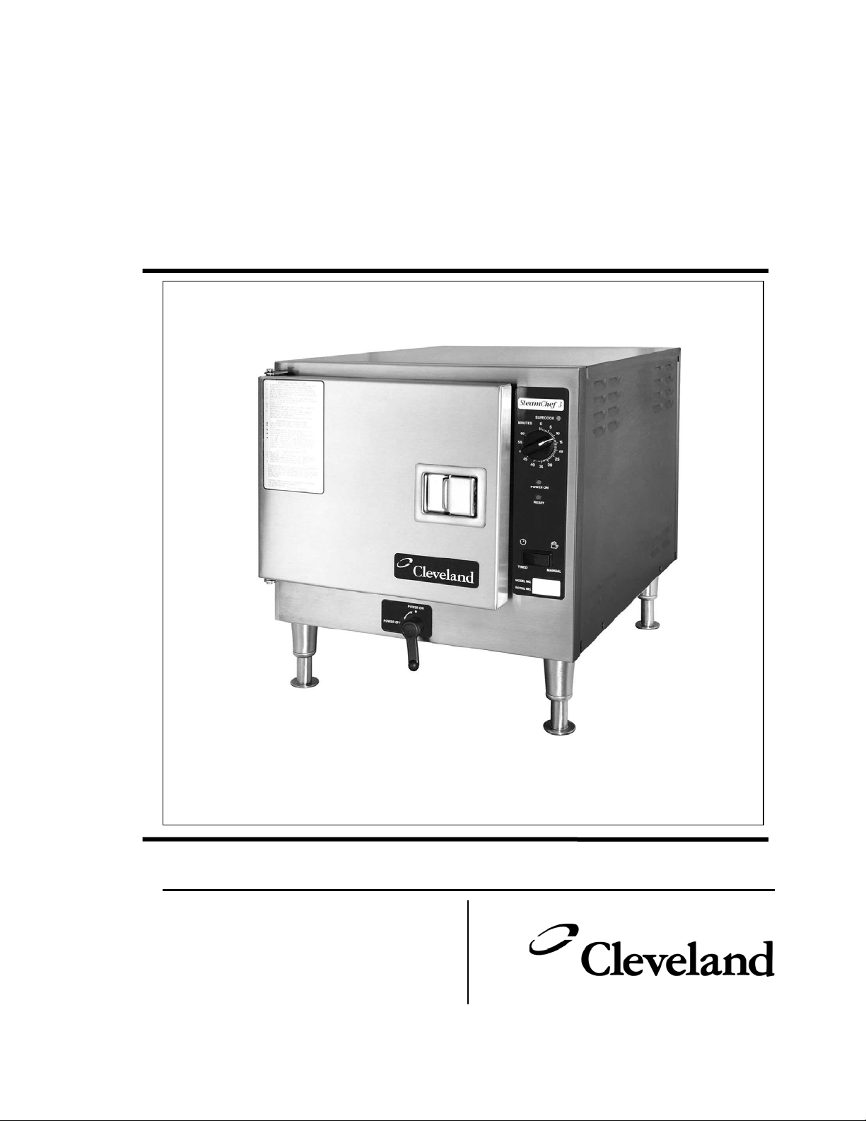
Operators Manual
Installation, Operation, Use & Care
Steam Cooker and Rethermalization Unit
Series: SteamChef¥ 3 Model 22CET3A Series
1333 East 179th Street
Cleveland, Ohio 44110
Phone: (216) 481-4900
Fax: (216) 481 3782
22CET3-OPM A 2/03
Page 2
FOR THE USER
FOR YOUR SAFETY
Do not Store or use gasoline or
other flammable vapors or liquids
in the vicinity of this or any other
appliance.
WARNING
Disconnect power before servicing
Improper installation, adjustment, alterations,
services or maintenance can cause property
damage, injury or death. Read the
installation, operating and maintenance
instructions thoroughly before installing or
servicing this equipment.
WARNING
IMPORTANT
ALL SERVICE MUST BE PERFORMED BY A QUALIFIED CLEVELAND
RANGE TECHNICIAN.
RETAIN THIS MANUAL FOR YOUR REFERENCE
Page 3

Operators and Installation Manual
SteamChef¥ 3 Steam Cooker and Rethermalization Unit
Table of Contents
CHAPTER PAGE
CHAPTER 1. INTRODUCTION …………………………………………..……………………….… 1
A. OPERATIONAL SAFETY…………………………………………………………….…..……………… 1
B. PRODUCT INFORMATION …………………………………..……………………………………….. 2
1. Model Number……………………………………………………………………………………..…. 2
2. Serial Number …….…………………………..……………………………………………..……… 2
3. Product information Plate ………………………………………..………………………….……… 2
4. “SteamChef¥ 3” Model No. 22CET3A Product View ……………..………….…..…………...… 3
CHAPTER 2. OPERATION ………………………………………..…………….……………………… 4
A. GENERAL OPERATION ………………………………………..…………………….………………… 4
1. Main External Power Switch ……………………………….……………………………………….. 4
2. Door Interlock Switch …………………………………………………………………………….….. 4
3. KleanShield¥ ………………………………………………….………………………………….….. 4
4. Inspecting the Cooking Compartment ……………..……………………………….…………….. 5
5. Power ON (Auto Water Fill/Automatic Preheat) ………………….…………….………………… 6
6. Preheating the Steamer…………………………………………………………………………..…. 6
7. High Limit Reset ……………………………………………………………………………….….…. 6
8. Energy/Water Saver Feature ………………………………………………………….……..….…. 6
B. CONTROL PANELS ……………….……………………………….……………………………..….… 7
1. Dial Timer Control Panel ………………………………………………………………….………… 7
a. General Operation………………………………………………………………………….….… 7
b. Manual and Timed Modes …………………….……………………………….………….…… 7
(1) Manual Mode ………………………..….………………………………….……………..… 7
(2) Timed Modes …………………………………………………………………….………..… 7
2. “ON/OFF” Control Panel …………………………………….……………………….……………. 8
a. Cooking Operations – ON/OFF Control Panel ……………………………….…………..… 8
b. Operating the ON/OFF Control …………………………………….…………………….…… 9
C. COOKING WITH THE STEAMCHEF¥ 3 ……………………………………………………….….…. 9
1. Operating and Cooking Procedure – Timed Cook Mode ……………….………………….…… 10
2. Operating Procedure – Manual Mode …………………………………………………………….. 11
3. Using the SteamChef¥ 3 to Rethermalize Food ……………..…………………………………. 12
D. SHUTDOWN AND CLEANING PROCEDURE..……………………………………………………… 13
CHAPTER 3 – PREVENTATIVE MAINTENANCE AND TROUBLESHOOTING….. 14
A. MAINTENANCE………………………………………………………………………………………….. 14
1. Maintenance Records……………………………………………………………………………….. 15
2. Daily Maintenance………………………………………………………………………………….… 15
a. Checking and Changing the Water……………………………………………………………. 15
b. Cleaning the Steamer…………………………………………………………………………… 15
3. Yearly Maintenance – Cleaning the Water Strainers ……………..……………….………….… 15
B. OPERATORS TROUBLESHOOTING GUIDE………………………………………………………… 16
CHAPTER 4 – INSTALLATION……………………………………………………….….
A. GENERAL………………………………………………………………………………………………… 19
B. INSTALLATION OF THE STEAMCHEF¥ 3 …………………………………………………………. 19
19
(Continued on Following Page)
Page 4

Table of Contents (continued)
CHAPTER
1. Locating the Steamer……………………………………………………………………………….. 20
Location and Clearance Requirements of the Steamer ………………………………………... 20
2. Installation Using Cleveland Range Stand Model No. ES222834 …………………………….. 21
3. Installation of SteamChef¥ Steamers on the Model No. ES222824S Sacking Stand …..….. 22
4. Installing the Legs …………………………………..……………………………………………… 24
5. Positioning and Leveling the Steamer …………………………………..….……………………. 25
6. Installation of the KleanShield¥ ……………………………………..…..….……………………. 25
7. Installing the Fan Guard ………………………………………………..…..….…………………… 25
8. Install Slide Racks and Rear Vent ………………………………………………………………… 25
9. Install the Free Air Vented Drain Lines ……………………………………………………………. 26
10. Water Supply Requirements and Installation ……………………………………………………. 27
a. Water Supply Requirements …..…….………………………………..…………………..…. 27
b. Install Water Supply Lines …..…….……………………………………………………...…. 27
c. Testing Water Supply Lines …………………………………………………………..……… 29
11. Install Electric Power Lines………………………………………………………………………… 29
C. STARTUP AND CHECKOUT…………………………………………………………………………... 30
1. Installation Checkout ……………………………………………………………………..………… 30
Notes on Installation ……………………………………………………………………..……… 30
2. Operating Test and Final Checkout Procedure………………………………………………….. 31
a. Startup Procedure……………………………………………………………………………… 31
b. Drain Rinse Inspection ……………………………………………………………………….. 32
c. Operating Tests and Final Checkout Procedure (Sequence of Operation) ….…………. 32
PAGE
CHAPTER 4 – STEAM COOKING GUIDE …………..……………………………..…. 35
A. INTRODUCTION ………………………………………………………………………………………… 35
B. SIZING UP PAN CAPACITY ………………………………………………………………..……..…. 36
1. Serving Sizes – How Much? How Many? …………………………….………………..………… 36
2. Reference Charts for Typical Pan Capacities …………………………………..……………….. 36
C. CONVECTION STEAMER – SUGGESTED TIMER SETTING GUIDELINES …………………... 37
D. STEAMING TIPS – LOBSTER – CRAB - SHRIMP ………………………………………………... 39
1. Live Lobster and Crabs …………………………….………………………………..…..………… 39
2. Lobster Tail 8 oz. …………………………………..……………………………………………….. 39
3. King Crab Legs …………………………….……………………………………………..………… 39
4. Shrimp …………………………………..…………………………………………………………... 39
Page 5
CHAPTER 1 – INTRODUCTION
To use a SteamChef¥ 3 steamer safely and effectively, each operator must read and understand this
section completely before starting operation. The owners and operators of the steamer should retain these
instructions in an easily accessible location for future reference and training.
The owner(s) and operator(s) of the steamer must be aware that steam can cause serious injuries and
equipment damage. Pay particular attention to the Operational Safety section of this chapter, and the
WARNINGS and CAUTIONS displayed in this manual and on the equipment.
WARNING
DO NOT ATTEMPT TO START OR OPERATE a SteamChef¥ 3 steamer during a
power outage.
DEATH, INJURY, AND EQUIPMENT DAMAGE could result from the improper
installation of a steamer.
Before starting a recently installed or repaired steamer, be sure it has been installed by
qualified personnel according to the instructions found in CHAPTER 4 of this Manual.
A. OPERATIONAL SAFETY
The safe and effective operation of any steamer depends upon proper installation, use, maintenance, and
repair. Operational safety must encompass all of these factors. This Operational Safety section outlines the
minimum safety policies that should be considered when using one or more SteamChef¥ 3 steamers. It is
assumed that any operational safety program must be tailored to the specific site and use of the equipment.
Burn hazards are present in any professional food service operation. When using the steamer, observe the
following precautions.
x
The SteamChef¥ 3 is a constantly cooking appliance and is in some cooking or standby mode
whenever it is turned ON. As such parts of this appliance will ALWAYS BE HOT.
x
Remember at all times that steam can cause severe burns.
x
Never operate a SteamChef¥ 3 steamer without the KleanShield¥ properly installed in the bottom
of the water reservoir or the fan guard installed over the fan.
x
When checking inside the steamer always open the door slowly and stand to the side and back
away from the steamer.
x
Open the door slightly to allow steam to vent before looking or reaching into cooking compartment.
x
Do not reach into the cooking compartment until the steam has cleared and the cooking fan has
ceased rotating.
x
Do not reach into steamer or handle hot items without wearing heatproof gloves. Wet or damp
gloves conduct heat, and may cause burns when touching hot items.
x
Do not use anything but your hands to operate the controls of the steamer.
x
Do not block the vents on the side or rear of the unit or obstruct the flow of ventilation air to the
steamer. Do not store articles on top of the unit.
x
Do not ever tilt the unit if the main external power to the unit is on, or if the drain is closed.
The steamer requires a minimum of service if properly operated and maintained by trained personnel. The
following steps will help keep the steamer in a safe, efficient operating condition.
1. Do not store or leave combustible materials near the steamer. Keep the area around and under the
steamer free of combustible materials.
2. Non slip draining mats should be on the floor in front of the steamer to prevent slipping accidents from
spilled water.
3. Train all personnel who will use the steamer. Make sure personnel know how to operate the steamer,
clean the interior and exterior, and drain the unit.
1
Page 6
4. Operating personnel must be able to recognize problems, and report them so that corrective actions
can be taken by trained personnel as outlined in the troubleshooting charts found in Chapter 3 of this
manual.
5. Conduct regular steamer inspections. Check for water line leaks, door seal, drain and drain valve leaks,
clogged drain or KleanShield¥, dirty water level sensors, and steamer control malfunctions.
6. Follow the instructions for steamer maintenance found in this manual.
7. Remove spilled food from the surface of the KleanShield¥ and the inside of the steamer reservoir.
Never push solid food remnants down the KleanShield¥ opening or the reservoir drain opening.
8. Before each use of the steamer, inspect the drain and KleanShield¥ for blockage. Inspect the door
gasket assembly, water level sensors, KleanShield¥, fan guard and slide racks for proper installation
and cleanliness.
9. Allow only Cleveland Range authorized service representatives to service the steamer.
10. Use only factory authorized repair parts.
11. Maintain written records of steamer maintenance and service. Each record should include at least:
x
The date of the service or maintenance.
x
A description of the service, maintenance or repair performed. Include part numbers if applicable.
x
Copies of purchase order(s) and invoice(s) for repair parts and service.
x
The name and signature of the person performing the maintenance or service.
B. PRODUCT INFORMATION
Cleveland Range, LLC assigns two product identification numbers to each steamer: a model number and a
serial number. The model number identifies the product characteristics. The serial number identifies the
individual unit. The Model Number and Serial Number are also located on the control panel as well as the
product information plate for your convenience in accessing this information.
1. Model Number
This manual covers the SteamChef¥ 3 Model No. 22CET3A Steam Cooker and Rethermalizer. Each
character of this model number identifies a characteristic of the steamer. The SteamChef¥ 3 Model No.
22CET3A is 22 inches wide, is a Convection Steamer, an Electric Tabletop Model, cooks up to 3
standard 2 ½” pans of food and A equipped with Auto fill/drain option. This manual covers all standard
features and options available on SteamChef¥ 3 electric steamers.
Other than selection of options, there are presently no significant design, parts, or operating differences
among steamers with this model number. Figures 1-2 and 1-3 illustrate the major external features.
2. Serial Number
During manufacture, SteamChef¥ 3 Steamers are assigned individual serial numbers. Whenever any
inquiry is made with Cleveland Range regarding a steamer the serial number should be referenced.
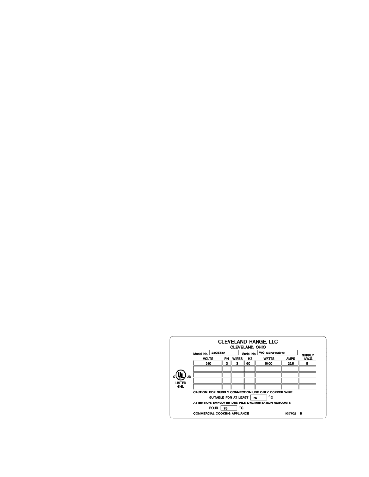
3. Product Information Plate
The Product Information Plate on
the rear of the unit lists the model
and serial number as well as the
power and wiring requirements of
the steamer. Refer to Figure 1-3 for
the location of the plate. Figure 1-1
illustrates a typical SteamChef¥ 3
Product Information Plate.
Figure 1-1 SteamChef¥ 3 Product Information Plate
2
Page 7
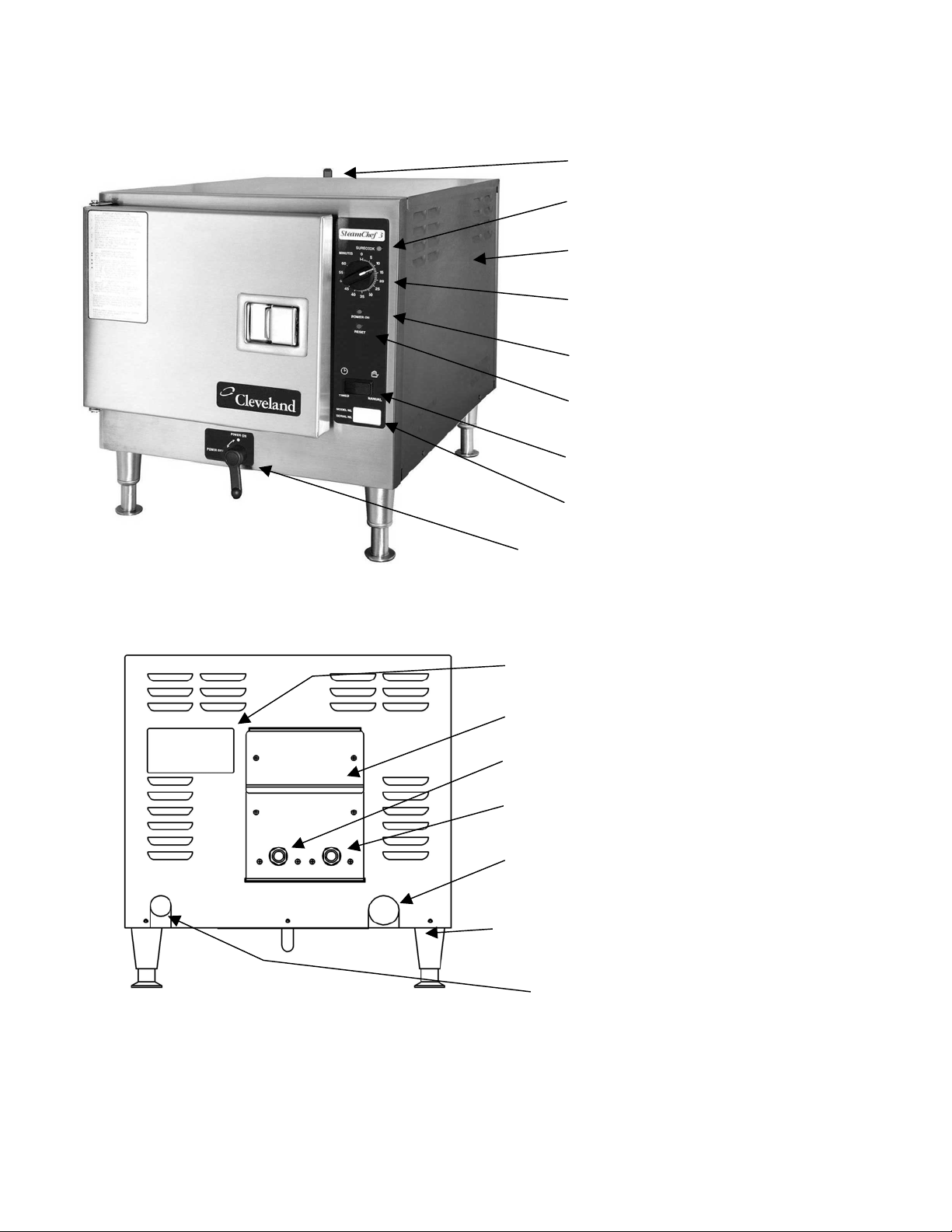
4. “SteamChef¥ 3” Model No. 22CET3A Product Views
Cavity Vent from Drain
“SureCook” Indicator
Removable Side Panel
Timer Control with Thermostatic
Control Feature
Power ON Indicator
Hi Limit Reset Indicator
Manual/Timed Selector Switch
Model/Serial Number Insert
Drain Valve/ Main Power ON/OFF Lever
-
Figure 1-3 SteamChef¥ 3 Steam Cooker Rear View
¥
Product Information Plate
Includes Serial/Model
Number Information
Rear Access Panel for Fan
Water Fill Connection
Condenser Connection
Outlet for Drain/Vent
Assembly
4” (102mm) Adjustable
Legs with Skid Resistant
Flanged feet
Opening for Electrical
Conduit Connection
3
Page 8
CHAPTER 2 – OPERATION
A. GENERAL OPERATION
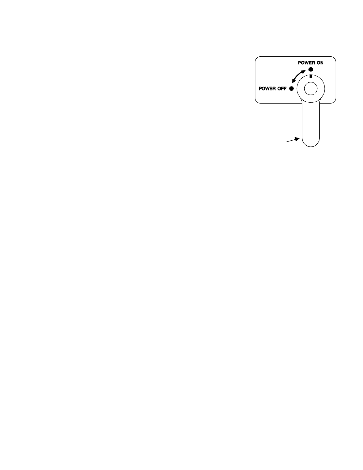
1. Main External Power Switch
MAIN POWER SWITCH
Usually the steamers main external power switch is left ON. If
the main power switch was left in the OFF position, turn it ON
as follows.
a. Turn the ON/OFF lever/switch to the OFF position.
b. The control settings are not important in this
procedure. The control panel circuits are not powered
while the ON/OFF lever/switch is set to OFF.
c. Refer to the main power switch in Figure 2-1, and turn
on electric power to the steamer.
2. Door Interlock Switch
The steamer compartment of the SteamChef¥ 3 is equipped with an automatic steam cutoff switch, which
turns OFF the production of steam and shuts down the convection fan and condenser whenever the door to
the compartment is opened. NOTE: That even though the continued production of additional heat ends as
soon as the door is opened, it may take up to a minute for residual heat in the system to stop producing
steam in the cooking compartment and for the fan to stop rotating. To avoid possible injury always wait until
this residual steam has cleared and the convection fan has stopped rotating before reaching into the
cooking compartment. Remember the SteamChef¥ 3 is always heating in either the standby heat
mode or steam cooking mode, whenever the main power switch is in the ON position and the
steamer door is closed.
3. KleanShield¥
This unit is equipped with the KleanShield¥ for improved maintenance, cooking and safety performance in
the steam cooking of food. The KleanShield¥ (See Figure 2-2) is located in the bottom of the water
reservoir of Cleveland Range SteamChef¥ Cookers and provides the following benefits to the
owner/operator:
Figure 2-1 Main Power Switch
SteamChef¥ 3
x By collecting all of the drippings of food being
cooked from entering and contaminating the
reservoir water.
x By keeping the water cleaner, less maintenance is
needed in the daily operation and cleaning of the
interior of the steamer.
x It directs the steam being produced around the sides
of the pans to insure more even distribution of the
steam.
x It prevents the operator from accidentally coming in
contact with the reservoir water during the placing or
removal and food from the cooking compartment.
x It also prevents spilled food from pans from falling directly into the reservoir and splashing out
scalding water.
x The KleanShield¥ is removable and dishwasher safe allowing for easy cleaning.
Please read the following Important Use and care Instructions for the KleanShield¥
a. Never operate a SteamChef¥ Steamer without a properly installed KleanShield¥.
b. To install the KleanShield¥, the side pan racks must first be removed from the steamer.
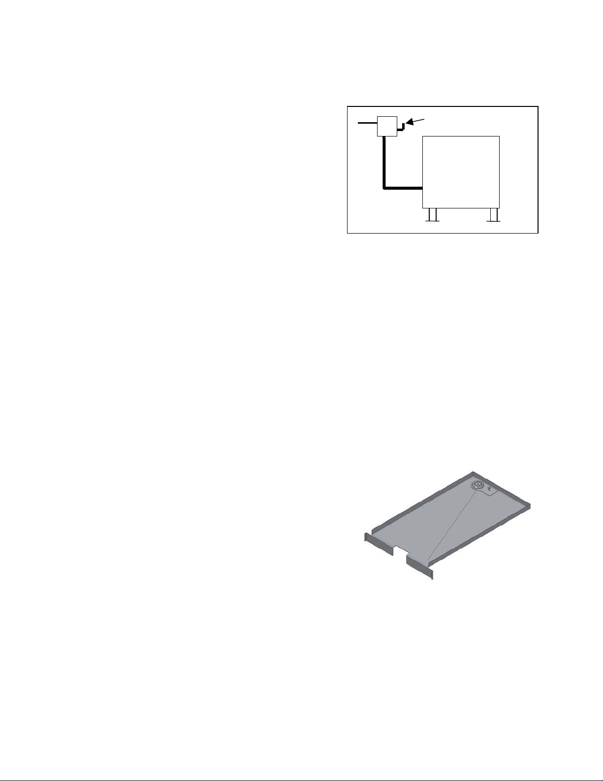
Figure 2-2 the KleanShield¥
4
Page 9
c. Place the KleanShield¥ into the steamer with
pipe extension towards the back and facing
down. Set the KleanShield¥ in place over the
corresponding pipe extending out of the bottom of
the steamer reservoir. See Figure 2-3.
d. The KleanShield¥ is installed properly when the
pipe from the KleanShield¥ is fitted into the
corresponding pipe in the bottom of the steamer
and its legs are flush against the bottom of the
steamer. See Figure 2-6.
4. Inspecting The Cooking Compartment
a. Before turning ON the power switch/lever to the
FIT UP OF
KLEANSHIELD¥
SteamChef¥ 3, the entire inside of the steamer
must be thoroughly cleaned.
b. All food debris should be wiped clean and the
drain openings and the water level sensors shall
Figure 2-3 KleanShield¥
Installation
be inspected and cleaned of any residue or
debris (See Figure 2-4).
c. The door gasket assembly, KleanShield¥, fan
guard and slide racks should be inspected for
proper installation and cleanliness. See Chapter
2, Section A, Part 3 for proper installation of the
KleanShield¥.
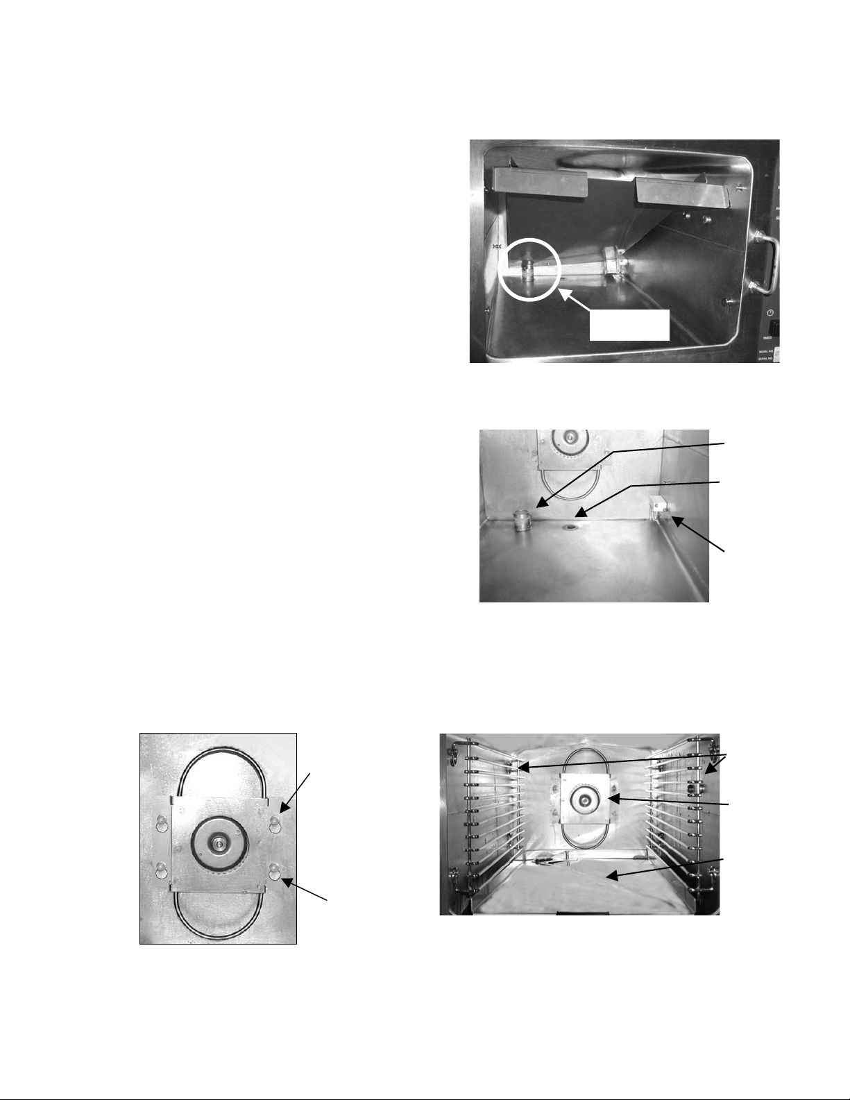
x To properly install the fan guard, hold the fan
guard so that the large ends of the keyholes
are towards the bottom of the steamer. Place
all four openings over the mounts located on
the rear wall of the steamer and pull it down
so that the narrow ends of the slots are pulled
Figure 2-4 Inspecting
Compartment drains
tight over the mounts. See Figure 2-5.
d. Make sure that the KleanShield¥ drain is clear. See Figure 2-6.
e. It is also recommended that a small amount of water (about a quart) be poured through the
KleanShield¥ drain. Check that water flows out the drain.
OVERFLOW
DRAIN
RESERVOIR
DRAIN
OPENING
WATER
LEVEL
SENSOR
ASSEMBLY
FAN GUARD
SHOWN PULLED
DOWN TO LOCK IT
Figure 2-5 Fan Guard Shown in
Installed Position
IN PLACE
LARGE END OF
KEYHOLE AT
BOTTOM
REMOVABLE
PAN RACKS
FAN
GUARD
KLEANSHIELD¥
Figure 2-6 Inspecting Compartment
Interior Accessories
5
Page 10
5. Power ON (Auto Water Fill/Automatic Preheat)
(
)
a. Check that the water supply valves to the unit are open.
b. Set the timed manual switch to timed (dial timer models) or set
the selector switch to OFF (ON/OFF control models).
c. Turn ON power to the steamer by turning the drain valve lever
clockwise (down) to close the drain (see Figure 2-7). The power
ON indicator will light and the unit will begin to fill automatically.
d. Close the door. Once the unit has filled to the minimal operating
level the heater will come ON, and the steamer will begin to
automatically heat the water supply to the standby cooking
temperature.
e. When the “SureCook” indicator light goes off the steamer has
completed its Preheat (this only applies for units equipped with a
timer). For ON/OFF control units it will take approximately 10 to
15 minutes for the unit to reach the standby heating temperature
ON/OFF LEVER
Figure 2-7 ON/OFF Lever
Shown in ON Position
depending on the wattage of the Steamer and the incoming
temperature of the water.
6. Preheating The Steamer
Preheating the steamer can help insure that the best productivity and consistent cooking is obtained. To
preheat the SteamChef¥ 3, simply turn the unit on approximately 15 minutes before you are ready to cook.
The unit will automatically go into the preheat mode and prepare the unit for cooking.
x
BEFORE PREHEATING, inspect and clean the compartment. After preheating, the compartment will
be too hot to inspect and clean safely.
7. High Limit Reset
This unit is protected by a high limit lockout, which acts to protect the unit from overheating. If the reset
light should come ON, a buzzer will sound continuously, the heating circuit of the steamer will be locked
out by the over-temperature circuit, and the steamer will not be able to be used for cooking until the unit is
reset. To reset the high limit use the following procedure:
a. If the reset indicator lights, turn OFF power to the unit at the ON/OFF lever.
b. Wait 15 minutes for the unit to cool and refill the unit with water according to the Power ON
instructions found in Chapter 2, Section A, Part 5.
c. If the condition should repeat itself see the operators troubleshooting section of this manual,
Chapter 3, Section B for further instructions.
8. Energy/ Water Saver Feature
This unit is equipped with an internal timer system, which automatically switches the unit to the standby
heat temperature if the unit is left in the Manual Mode (timer models) or the unit is left ON (ON/OFF
Control Models) for more than 60 minutes without opening the door. This feature has the following
benefits:
x It saves water by reducing steam loss and condenser water.
x By maintaining a lower temperature and not constantly producing steam, energy usage is reduced.
x Increases the steamer life.
x Because the unit automatically returns to the cooking temperature the next time the door is opened,
this feature has almost no effect on the operation of the equipment.
6
Page 11

B. CONTROL PANELS
The standard dial timer control panel (illustrated in Figure 2-8) has a mechanical timer that uses a
“SureCook” temperature compensation circuit, which allows the timer to count down only while the cooking
compartment is at cooking temperature. An optional ON/OFF control panel (illustrated in Figure 2-9) is also
available. The ON/OFF Control Panel, operates exactly like the dial timer control model in manual mode,
except a selector switch is used to change the steamer from the standby heat mode to the cooking mode.
1. Dial Timer Control Panel
a. Cooking Operations – Dial Timer Control Panel
For safe, efficient operation of the steamer, the operator must, at a minimum, comply with all
cautions, warnings and instructions in the detailed operating procedures and be familiar with the
control panel shown in Figure 2-8. The operator must be familiar with all the operating features
explained in this manual before attempting to operate the steamer.
b. Manual and Timed Modes
The steamer has two operating modes: manual and timed. The TIMED/MANUAL rocker switch
selects the operating mode. Pressing the MANUAL end of the switch selects the manual operating
mode. Pressing the TIMED end of the switch selects the timed operating mode. Cooking
procedures are slightly different for each mode.
1). Manual Mode
The manual mode provides continuous steaming operation. The operator starts and stops steaming
operations manually. See the Operating and Cooking Procedure – Manual mode in Chapter 2,
Section C, Part 2 for more information. A thermostat controlled “SureCook” indicator light located on
the control panel indicates that the cooking compartment has not yet reached optimum cooking
temperature.
2). Timed Mode
x
The timer provides timed control of steaming operations. The timer starts and stops
steaming operations.
x
The mechanical timer control uses a “SureCook “ temperature compensation circuit that
effects only the timer. When operating, the timer ONLY COUNTS DOWN WHILE THE
COOKING COMPARTMENT IS AT AN EFFICIENT COOKING TEMPERATURE. This
provides totally automatic control of the steaming operation and assures uniform cooking
as the timer automatically compensates for food product defrosting and/or compartment
heat up time. Whenever the steamer is not at an efficient cooking temperature, the
compensation feature interrupts the countdown of the timer and the “SureCook” light is
illuminated.
x
To use the timer, simply set the timer to the desired time. The steamer will begin cooking
as soon as the timer is set. When the timer reaches zero the steaming functions will
automatically end and a buzzer will sound for 3 seconds to alert the operator that cooking
is complete. The cooking compartment will then revert to the standby-heating mode until
the next timing cycle is started.
x
Note the mechanical timer will not function when the Timed/Manual switch is set to
Manual, although the “SureCook
compartment is not yet at optimum cooking temperature.
” light will still illuminate to indicate that the cooking
7
Page 12
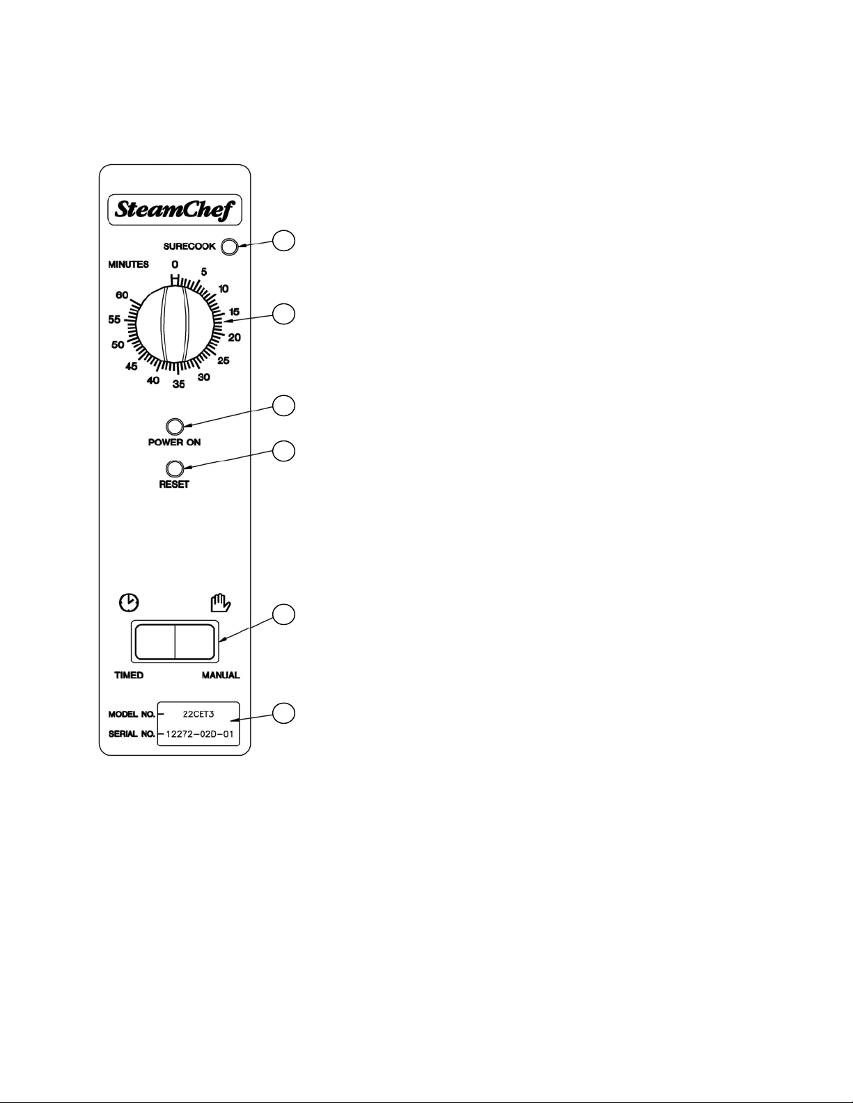
1. “SureCook” Indicator Light
This Amber light is lit whenever the cooking
compartment has not yet reached the optimum cooking
1
temperature. Note: when in the timed mode the timer
will not count down as long as this light is ON.
2. TIMER
2
This dial timer sets the operating time from 0 to 60
minutes. Turn the dial clockwise until it points to the
required number of minutes. When it reaches 0, a
buzzer sounds for 3 seconds.
3
3. POWER ON Indicator Light
When the Green indicator light is ON, power is ON to
4
the operating controls.
4. RESET Indicator Light
When this light is lit, it indicates that the high limit
circuit of the steamer has opened. This light will remain
ON, and a buzzer will sound until power to the unit has
been reset. See High Limit Reset in Chapter 2, Section
A, Part 7 for additional details.
5
5. TIMED/MANUAL Switch
The TIMED/MANUAL switch selects the manual or
timed operating mode.
x
6
Pressing the MANUAL end of the switch selects the
manual mode.
x
Pressing the TIMED end of the switch selects the
timed mode.
6. Serial Number/Model Number Display
Figure 2-8 Dial Timer Control Panel
2. ON/OFF Control Panel
a. Cooking Operations – ON/OFF Control Panel
For safe, efficient operation of the steamer, the operator must, at a minimum, comply with all
cautions, warnings and instructions in the detailed operating procedures and be familiar with the
control panel shown in Figure 2-9. The operator must be familiar with all the operating features
explained in this manual before attempting to operate the steamer.
8
Page 13
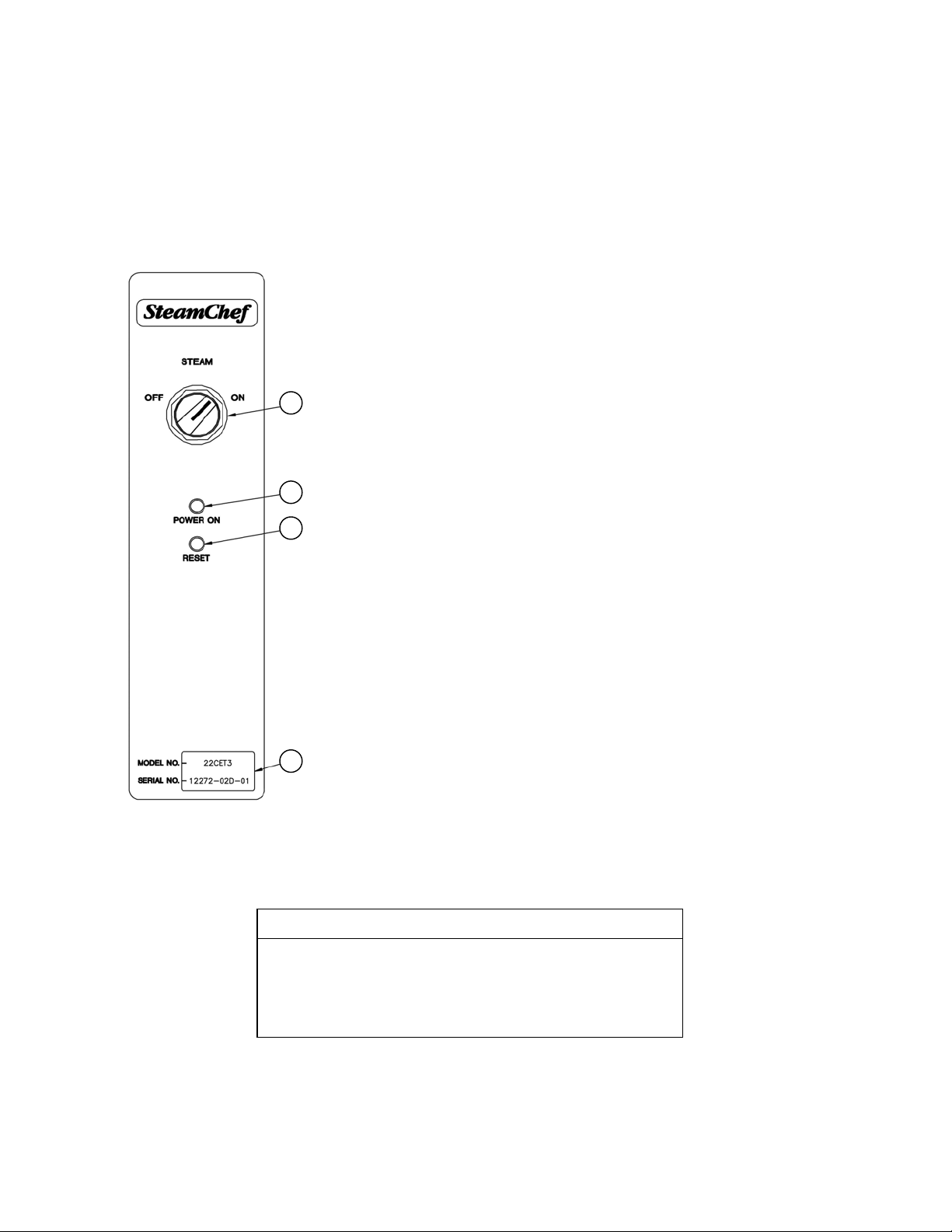
b. Operating the ON/OFF Control
This unit leaves all control of the cooking up to the operator. When turned ON cooking with this
steamer is the same as cooking with a dial timer control unit in the Manual Steam Mode.
NOTE: This unit is constantly in a hot mode whenever the main power lever is ON, the door is
closed and the unit is filled with water. When the selector switch of this unit is turned to the
OFF position, this unit will maintain the Standby Heat temperature in the compartment.
1. ON/OFF Selector Switch
When turned to the ON position the steamer will go
into the Constant Steam Mode and maintain the
compartment temperature at the cooking level for 1
1
hour unless the door is opened. When turned to the
OFF position the unit will be maintained at the
standby heating temperature.
2. POWER ON Indicator Light
2
When the Green indicator light is ON, power is ON
3
to the operating controls.
3. RESET Indicator Light
4. Serial Number/Model Number Display
4
Figure 2-9 On/Off Control Panel
C. COOKING WITH THE STEAMCHEF¥ 3
The SteamChef¥ 3 is a continuously operating appliance
and is constantly standing by and ready to cook whenever
the ON/OFF lever of the power control panel is in the ON
position.
When this light is lit, it indicates that the Hi-limit
circuit of the steamer has opened. This light will
remain ON, and a buzzer will sound until power to
the unit has been reset. See High Limit Reset in
Chapter 2, Section A, Part 7 for additional details.
IMPORTANT
9
Page 14
WARNING
When checking inside the steamer always open the door slowly
and stand to the side and back away from the steamer. Water
leaking from the door gasket can be a sign of a blocked drain. If
the drain is blocked, hot water can accumulate inside the
compartment and spill out when the door is opened.
1. Operating and Cooking Procedure – Timed Cook Mode
WARNING
Even though the heating elements are de-energized as soon as a door is opened, it
may take up to a minute for production of steam to end and residual steam in the
system to clear from the cooking compartment. To avoid possible injury always wait
until this residual steam has cleared before reaching into the cooking compartment.
Never operate a SteamChef¥ 3 Steamer without the KleanShield¥ properly
installed in the bottom of the water reservoir or the fan guard installed over the fan.
In timed mode, the timer starts and stops the cooking operation. When in the timed mode and the
compartment door is closed, the unit will maintain the compartment at the standby heat temperature
whenever the unit is not performing a timed cook operation.
(1) Refer to Inspecting the Cooking Compartment in Chapter 2, Section A Part 4. Inspect and clean the
drain, KleanShield¥ and cooking compartment as required.
(2) Refer to the Power ON instructions in Chapter 2, Section A, Part 5 and turn ON and fill the unit.
(3) If necessary, refer to Preheating the Steamer, in Chapter 2, Section A Part 6, and preheat the
cooking compartment.
(4) Slide the pans of food into the slide racks inside the steamer. Do not place pans or anything else on
the bottom of the compartment.
CAUTION
Some foods drip juices and food debris. Use a solid catch
pan under perforated pans when steaming food that will drip
excessive juices and debris. Failure to use a catch pan can
cause a clogged drain or KleanShield¥.
x
For best cooking results, use shallow, 2-1/2 inch deep, perforated pans without covers. These
give the best heat transfer and shortest cooking time.
(5) Close the steamer door.
(6) Check the control panel settings. At this point the settings should be:
x
The ON/OFF Lever is in the ON (down) position and the Power indicator light is lit.
x
The TIMED/MANUAL switch is in the TIMED (left) position.
10
Page 15

(7) Set the required cooking time. The timer will start counting down as soon as the compartment
reaches the minimum cooking temperature.
(8) When the timer reaches zero, a buzzer will sound for 3 seconds; the cooking circuit will turn OFF
and the unit will revert to the standby heat mode. The cooking cycle is complete.
WARNING
SEVERE BURNS may result from exposure to steam.
Do not open the steamer door before steam generation stops.
Stand back when opening the compartment door. Open the
door slightly to allow steam to vent before looking or reaching
into cooking compartment. Do not reach into cooking
compartment until the steam has cleared.
Do not reach into steamer or handle hot items without wearing
heatproof gloves. Wet or damp gloves conduct heat, and may cause
burns when touching hot items.
(9) Carefully open the cooking compartment door, and remove the pans from the slide racks.
x
If the steamer will be used again shut the door to maintain the cooking compartment
temperature.
x
If the steamer is not being used again during this shift, perform the Shut Down and Cleaning
Procedures, found in Chapter 2, Section D.
2. Operating and Cooking Procedure – Manual Mode
Manual mode allows the operator to personally control the cooking functions. The operator starts and
stops the steaming operations, and sets the cooking time including time for cooking compartment and
food heat-up time. Use the manual-cooking mode for:
x
A continuous supply of steam.
x
Maintaining the compartment temperature between cooking batches.
x
Remember that this unit is equipped with an energy saving feature. This automatically drops the
compartment into the standby heat mode, after an hour of operating in the manual mode without
interruption (such as opening the door). If Cooking times longer than the 60 minutes are desired, it
will be necessary to reset this timer circuit. To reset the timer without interrupting the continuous
cooking of the unit either quickly open and close the cooking compartment door, or switch the
TIMED/MANUAL switch to timed and back to manual.
Manual Cooking Procedure
Follow this procedure when cooking with the steamer in manual mode.
WARNING
Even though the heating elements are de-energized as soon as a door is opened, it
may take up to a minute for production of steam to end and residual steam in the
system to clear from the cooking compartment. To avoid possible injury always wait
until this residual steam has cleared before reaching into the cooking compartment.
Never operate a SteamChef¥ 3 Steamer without the KleanShield¥ properly
installed in the bottom of the water reservoir or the fan guard installed over the fan.
11
Page 16

(1) Inspect and clean the drain and cooking compartment as required. Refer to Inspecting the
Cooking Compartment in Chapter 2, Section A, Part 4.
(2) Refer to the Power ON instructions in Chapter 2, Section A, Part 5 and turn ON and fill the
unit.
(3) In manual mode, the operator can bring the compartment to cooking temperature by either
preheating or increasing the cooking time. If the operator chooses to preheat the cooking
compartment manually, refer to Chapter 3, Section A, Part 6, Preheating The Steamer.
(4) Slide the pans of food into the slide racks inside the steamer. Do not place pans or anything
else on the bottom of the compartment.
CAUTION
Some foods drip juices and food debris. Use a solid catch
pan under perforated pans when steaming food that will drip
excessive juices and debris. Failure to use a catch pan can
cause a clogged drain or KleanShield¥.
x
For best cooking results, use shallow, 2-1/2 inch deep, perforated pans without covers.
These give the best heat transfer and shortest cooking time.
(5) Close the steamer door. Select the manual mode by pressing the MANUAL end of the
TIMED/MANUAL rocker switch. The steaming cycle starts as soon as the switch is pressed.
Shortly after the door is closed, steam fills the cooking compartment.
(6) To stop manual mode steaming, press the TIMED end of the TIMED/MANUAL rocker switch
and verify that the timer is at zero. The cooking circuit is de-energized, and steam flow to the
cooking compartment gradually stops.
WARNING
SEVERE BURNS may result from exposure to steam.
Do not open the steamer door before steam flow stops. Stand back when
opening the compartment door. Open the door slightly to allow steam to vent
before looking or reaching into cooking compartment. Do not reach into
cooking compartment until the steam has cleared.
Do not reach into steamer or handle hot items without wearing heatproof gloves.
Wet or damp gloves conduct heat, and may cause burns when touching hot items.
(7) Carefully open the cooking compartment door, and remove the pans from the slide racks.
x
If the steamer will be used again shut the door to maintain the cooking compartment
temperature.
x
If the steamer is not being used again during this shift, perform the Shut Down and
Cleaning Procedures, found in Chapter 2, Section D.
3. Using the SteamChef¥ 3 to Rethermalize Food
The SteamChef¥ may also be used to reheat/rethermalize previously cooked and/or refrigerated
foods to serving temperature in minutes. To use the SteamChef¥ 3 to rethermalize food, use the
following procedure:
x Use the SteamChef¥ 3 in the Manual Cooking Mode as outlined in Chapter 2, Part C, Section 2,
and cook the food to a safe serving temperature, 160-170 ˚F for most foods.
12
Page 17

x Depending on initial food temperature and density, most foods should be rethermalized to a serving
temperature in 10 to 40 minutes.
x Always check internal temperature of food with a thermometer to determine when it has been
rethermalized to a safe temperature (160° to 170°F).
x Remember that this unit is equipped with an energy saving feature. This automatically drops the
compartment into the standby heat mode, after an hour of operating in the manual mode without
interruption (such as opening the door). If Cooking times longer than the 60 minutes are required to
rethermalize a particular load of food, it will be necessary to reset this timer circuit. To reset the
timer without interrupting the continuous cooking of the unit either quickly open and close the
cooking compartment door, or switch the TIMED/MANUAL switch to timed and back to manual
NOTE: Cooking times may be longer for some foods and/or larger loads, especially when using 6
kW SteamChef¥ 3 models.
D. SHUTDOWN AND CLEANING PROCEDURE
This procedure should be performed at the end of each day or shift.
WARNING
Do not use a hose or water jet to clean this appliance.
CAUTION
When cleaning do not pick up or tilt the SteamChef¥ 3. If it is absolutely
necessary to move a SteamChef¥ 3 for cleaning, turn OFF power at the main
external power supply switch.
Catastrophic damage can result from shifting the SteamChef¥ 3 more than 10˚
out of level while power is turned on at the main external power supply switch.
The steamer MUST BE LEVEL BOTH FRONT TO BACK AND SIDE TO SIDE in
all mounting arrangements.
1. Open the steamer door and allow steamer to cool.
2. Turn the ON/OFF lever counter-clockwise (up) so that the white reference marker on the lever is
pointing directly left to turn the power OFF, de-energize all controls and drain the steamer. The
steamer will begin a 3-minute drain rinse cycle to clean the drain system.
WARNING
Inside of steamer stays hot for a long time. Be careful
when cleaning inside steamer compartment.
3. Remove any spilled food from the surface of the KleanShield¥. Never push solid food remnants
down the KleanShield¥ opening or the reservoir drain opening.
4. Remove the slide racks, fan guard and KleanShield¥. Wash and rinse slide racks, fan guard and
KleanShield¥ separately or clean them in a dishwasher according to health requirements.
5. Remove any spilled food from inside compartment and clear any residue from the drain valve and
the KleanShield¥ drain opening. Clean the interior of the compartment thoroughly, to remove all
13
Page 18

food particles. Use a soft bristle brush to clean the water sensor, temperature probe and to remove
stubborn food particles. Do not use abrasive cleaning compounds or steel wool.
6. After all the particulate matter has been removed, wipe down the interior of the cooking
compartment, particularly below the normal operating level, with a vinegar solution. When done
daily this will prevent the buildup of calcium and other mineral deposits left over from the boiling of
water, and prevent scale buildup in the steamer. Rinse the inside of steamer compartment and
drain valve thoroughly with clean water.
7. Inspect the probe assembly and clean it with a vegetable brush or similar non-abrasive cleaning
means. If detergent has been used to clean the inside of the steamer, be sure and thoroughly rinse
off the probe assembly with a vinegar solution. If detergent residue is not completely rinsed from the
probe assembly the film residue can prevent the water level control from properly operating.
8. Clean the door assembly.
x
Remove the door gasket assembly (see Figure 2-10).
x
Note the keyhole slots on the door and the retaining pins
on the gasket assembly. Grasp the gasket assembly at
the sides and lift up and towards you to remove the
assembly.
x
Clean all surfaces of the gasket assembly, as well as the
inside of the door, by wiping with a damp cloth.
x
Rotate the liner assembly 180q and replace the gasket
assembly by sliding the retaining pins into the keyhole
slots. Either long edge of the gasket assembly can be
positioned at the top. Periodic rotating of the door
assembly will increase the door gasket life.
Figure 2-10 Door Gasket Assembly
9. Replace the cleaned KleanShield¥ (See Chapter 2, Section A, Part 3), slide racks and fan guard.
WARNING
Never operate a SteamChef¥ 3 Steamer without the
KleanShield¥ properly installed in the bottom of the
water reservoir or the fan guard installed over the fan.
10. Wipe the exterior with a damp cloth only. NEVER HOSE DOWN THE STEAMER. Electrical
components inside the unit will not function correctly if wet or damp and may cause a shock hazard.
11. After cleaning, leave the steamer door open until the next steamer operation. This prevents
compartment odor buildup and increases gasket life.
CHAPTER 3. PREVENTATIVE MAINTENANCE AND
TROUBLESHOOTING
A. MAINTENANCE
Maintenance on the steamer must be performed on a regular basis to keep the unit running properly and
efficiently. By following the simple maintenance instructions in this chapter and cleaning the equipment
regularly as outlined in Chapter 2, Part D, problems with the steamer will be kept to a minimum. As with any
preventative maintenance schedule, the frequency of steamer maintenance may need to be increased,
depending on equipment usage and water quality. If problems do occur, refer to the Troubleshooting Guide
in this chapter. For more information on product and services, contact your sales representative.
14
Page 19

1. Maintenance Records
Make a file solely for maintenance and repair records. Keep a written record of daily, weekly, monthly, and
yearly maintenance. These records will protect warranty coverage, help personnel to know when to perform
various maintenance procedures, help keep the SteamChef¥ 3 cooking properly and assist service
personnel.
2. Daily Maintenance
a. Checking and Changing the Water
When using the SteamChef¥ 3 frequently check the water, especially if cooking with perforated
pans. Although, most food drippings will be caught by the KleanShield¥, the water may still become
soiled from occasional spilled food that falls over the edge of pans or when removing and loading
food into the steamer. Replace the water as outlined below whenever the water becomes cloudy or
heavily contaminated with food particles. At the very least CHANGE THE WATER IN THE
STEAMCHEF¥ 3 AT LEAST EVERY DAY IN ORDER TO MAINTAIN FOOD QUALITY AND
KEEP THE STEAMER SANITARY.
Note: It may be necessary to change the water several times a shift, especially if cooking strong
flavored foods or with perforated pans.
1) Open the steamer door and allow steamer to cool.
2) Turn the ON/OFF lever counter-clockwise (up) so that the white reference marker on the
lever is pointing directly left to turn the power OFF, deenergize all controls and drain the
steamer.
3) Remove the KleanShield¥. Remove any food particles and rinse the KleanShield¥ with clean
water.
WARNING
Inside of steamer stays hot for a long time. Be careful
when cleaning inside steamer compartment.
4) Remove any spilled food from inside compartment and rinse any residue from the drain valve
and the KleanShield¥ drain.
5) Replace the KleanShield¥ (see Chapter 2, Section A, Part 3).
6) Turn ON power to the steamer by turning the drain valve lever clockwise (down) to close the
drain (see Figure 2-7). The power ON indicator will light. The steamer will automatically begin
filling with water to the normal operating level.
7) Close the door. The “SureCook” indicator will light (timer models only), and the steamer will
begin to automatically heat the water supply to the standby cooking temperature.
8) When the “SureCook” indicator turns OFF (timer models only) the Steamer is now ready to
begin cooking.
b. Cleaning the Steamer
Clean interior and exterior of the steamer according to the shutdown instructions in Chapter 2, Part
D at least once per day if not at the end of each shift.
3. Yearly Maintenance – Cleaning the Water Strainers
Clean the water line strainers at least once a year as follows:
15
Page 20

NOTE: When the steamer is first installed, check the strainer more frequently to find out how often it must
be cleaned.
1. Turn OFF power to the streamer at the main electrical disconnect switch/breaker.
2. Close the valves in the steamer water supply lines.
3. Unscrew the hoses from the inlet fittings located on the rear of the
steamer.
4. Remove the filter washers (Figure 3-1) from the outlet of the hoses
and wash them with clean water.
5. Check the filter washer for wear and replace it if necessary.
6. Put the filter washers into each of the water inlets and reconnect the
hoses to the back of the steamer. Note if treated water is used to
supply water to the reservoir, make sure that it is connected to the
left inlet at the rear of the steamer (See Figure 4-1), which provides
feed water for the production of steam.
7. Open water supply valve(s) and check for water leaks.
8. Turn back on power to the steamer at the main electrical shutoff/breaker.
B. OPERATORS TROUBLESHOOTING GUIDE
The Troubleshooting guide includes a list of symptoms that may be encountered during routine operation
and maintenance. The first column on the left (PROBLEM) describes these symptoms. The second column
lists the possible causes for the problem in column one. The third column lists possible remedies for the
problems and causes in columns one and two. The causes and remedies are listed in the order they should
be checked, with the least costly and easiest to repair listed first. The third column also refers to notes that
are grouped at the end of the troubleshooting guide. Refer to these notes when instructed to do so.
Figure 3-1 Filter
Washer Assembly
PROBLEM POSSIBLE CAUSE REMEDY/REFERENCE
Power indicator light does not
turn ON when ON/OFF lever
is in the ON position.
Power ON and steamer does
not fill
Control panel power indicator
light ON, and steamer does
not come up to cooking
temperature or produce
steam.
Table 3-1 Trouble Shooting Guide
Power turned OFF at main external
power switch.
ON/OFF lever not fully turned to the ON
position.
Inoperative controls or indicator. See note #1
Water supply to steamer shut OFF Open water supply lines.
Water line strainer and/or external filter
system clogged.
Water sensor is grounded. Rinse water sensor assembly thoroughly
Inoperative controls or solenoids. See notes #1 and #5
Door interlock switch not engaged. Close door completely.
Water supply to steamer shut OFF Open water supply lines.
Water line strainer and/or external filter
system clogged.
Unit is in the timed mode and timer is not
set (Dial timer control models only)
Hi-limit switch has tripped. Reset steamer according to instructions
Inoperative controls. See note #1.
(Continued on next page)
Turn ON power at main power switch.
Turn lever to the full ON position.
Clean water supply strainer and/or filter
system.
with vinegar solution.
Clean water supply strainer and/or filter
system.
Change to manual mode or set the timer.
found in Chapter 2, Section A, Part 7. If
condition repeats itself see note #1.
16
Page 21

PROBLEM POSSIBLE CAUSE REMEDY/REFERENCE
Steam and/or water draining
around the compartment door.
See Warning under note #7.
Abnormal amount of steam
coming from drain or vent.
Abnormal amount of steam
coming from drain during
draining of steamer
Compartment bottom dirty
with food drippings.
Table 3-1 Trouble Shooting Guide (Continued)
Either the vent, the drain to the vent or
the KleanShield¥ opening is clogged or
covered.
Door gasket or door parts worn. See note #1.
Hot water instead of cold water
connected to the condenser water line
External drain or vent not properly
installed, should be free air vented and
pitched down.
Steamer not level. See note #2.
Condenser not operative See note #1.
Hot water instead of cold water
connected to the condenser water line
External vent is not installed in drain tee See notes #2 and #3.
Inoperative controls See note #1
ON/OFF lever/switch is not turned fully to
the OFF position
Water line strainer and/or external filter
system clogged.
Hot water instead of cold water
connected to reservoir fill line
Inoperative controls. See note #1.
KleanShield¥ not installed Install KleanShield¥ to catch food
Juices and/or food leaking from pans
during loading and unloading of steamer.
Clear vent or collector opening and/or
clean the drain with USDA approved drain
cleaner and flush drain thoroughly with
fresh water as applicable. If condition
persists see note #1.
See note #2 and #3.
See notes #2 and #3.
See note #2 and #3.
Turn lever/switch to the fully OFF position
to activate drain cooling feature.
Clean water supply strainer and/or filter
system.
See note #2 and #3.
drippings
Put a solid pan under perforated pans to
catch drippings, or put less food in pan.
Food takes too long to cook.
To verify the steamers
proper operation see
note #8.
Control panel Power indicator
is on, buzzer is buzzing
continuously and Reset
indicator is lit.
Steam coming out of the
exhaust.
Pans too close to the bottom of cabinet. Put pans in racks near top of cabinet.
Compartment overloaded with too much
food.
Suggested cooking times are usually
listed for cooking at sea level.
Convection fan inoperative See note #1.
Voltage too low for unit. See note #4.
High limit has been tripped. Reset steamer according to instructions
Inoperative controls. See Note #1.
A small amount of steam may issue from
the exhaust whenever the unit is in the
cooking mode.
Water line strainer and/or external filter
system clogged.
Hot water instead of cold water
connected to reservoir fill line
Inoperative controls. See note #1.
Put less food into pan. Use fewer pans.
Extend cooking times for altitudes above
2500 feet.
found in Chapter 2, Section A, Part 7. If
problem repeats itself, see Note #1.
This is normal operation of the steamer
NO action is necessary.
Clean water supply strainer and/or filter
system.
See note #2 and #3.
17
Page 22

TROUBLESHOOTING NOTES
1. A qualified service technician must repair problem or do the appropriate maintenance
2. Proper installation of the steamer is the responsibility of the owner or installer. A qualified installer or
technician should be contacted to correct the installation
3. Repairs to external plumbing should be done by a Licensed Plumber.
4. Repairs to external wiring should be done by a Licensed Electrician.
5. Should the automatic fill system fail for any reason the steamer will eventually stop heating when the
water level drops below the minimum operating level. Should this happen, the unit can continue to be
operated by manually filling the water reservoir with about a gallon of water approximately every halfhour, until service can be scheduled.
6. For more information on products and services, contact your nearest Authorized Sales Representative.
Call factory for a preventative maintenance program and water treatment systems: USA: (800)
338-2204, Canada: (800) 427-6668.
7. Whenever opening door, especially when water or steam is leaking around gasket heed the warning
below.
WARNING
When checking inside the steamer always open the door slowly and stand to the
side and back away from the steamer. Water leaking from the door gasket can be a
sign of a blocked drain. If the drain is blocked, hot water can accumulate inside the
compartment and spill out when the door is opened.
8. To evaluate whether a SteamChef¥ steamer is producing normal cooking performance, conduct the
Egg Test as follows (NOTE: this test is not valid for pressure steamers). A properly operating steamer
will produce cooked eggs as follows.
Turn on the steamer, and set the selector switch to the manual mode (or for ON/OFF models set the
selector to the ON position) so that steam is being produced. When wisps of steam has begun to exit
the steam vent, preheat the steamer by leaving it ON for ten minutes. After the compartment is
preheated follow the instructions as listed below.
x Place a fresh egg on a perforated steamtable pan in the middle of the cavity.
x Close the door and set the timer as directed by the size chart below
Size
Medium 12 minutes
Large 14 minutes
Extra Large 14 minutes
x When time is complete, carefully remove the egg and place in a container with cold water running
over it.
x Let cool under cold running water for 5 minutes.
x After cooling, crack egg shell and peal.
The result will be a perfectly hard boiled egg.
SteamChef¥
18
Page 23

CHAPTER 4. INSTALLATION INSTRUCTIONS
A. GENERAL
This equipment should only be installed by qualified, professional plumbers, pipe fitters and electricians.
x
The installation of this steamer must conform with the Basic Plumbing Code of the Building Officials and
Code Administrators International, Inc. (BOCA) as applicable, The National Electrical Code, ANSI/NFPA
No. 70-(latest edition) or the Canadian Electrical Code, CSA C22.2 as applicable, the Food Service
Sanitation Manual of the Food and Drug Administration (FDA) and all applicable state and local codes
and regulations.
x
The installation instructions must be read in their entirety before starting the installation of this steamer.
WARNING
Improper installation, adjustment, alteration, service or maintenance
can cause property damage, injury or death. The Installation,
Operating and Maintenance instructions should be read thoroughly
before installing or servicing this equipment
DO NOT INSTALL a SteamChef¥ 3 steamer suspected of damage.
Install the SteamChef¥ 3 steamer according to the policies and procedures
outlined in this manual.
x In order to properly install this steamer, the following requirements must be considered when selecting a
location.
a. A suitable electrical supply must be available matching the power requirements found on the rating
plate.
b. The location must have sufficient space to meet the clearance requirements of the steamer as
outlined in Chapter 4, Section B, Part 1, “Locating the Steamer”.
c. A potable cold water supply meeting the requirements outlined in Chapter 4, Section B, Part 10
“Water Supply Requirements and Installation” must be available
d. A suitable drain must be available within 12 ft. of the steamer.
B. INSTALLATION OF THE STEAMCHEF¥ 3
After selecting the steamer’s operating location the steamer can be positioned, and installed. After Startup
and Checkout, the SteamChef¥ 3 steamer will provide years of reliable operation.
CAUTION
Malfunctions and equipment damage may result from improper mounting.
The steamer MUST BE LEVEL BOTH FRONT TO BACK AND SIDE TO
SIDE in all mounting arrangements.
Catastrophic damage can result from shifting the SteamChef¥ 3 more than
10˚ out of level while power is turned on at the main external power supply
switch.
19
Page 24

1. Locating the Steamer
Location and Clearance Requirements of the Steamer
(1) Do not locate the steamer directly over a floor drain.
(2) Observe the following criteria when selecting an operating location for the SteamChef¥ 3
steamer.
x
Maintain a 3-inch operating clearance at the sides of the unit, and at least a 4-inch
clearance at the back.
x
A 12 in clearance is recommended on the right side for servicing the steamer.
x
Approximately 24 inches of clearance is recommended in front of the unit for opening the
door and standard pan clearance.
22.500
3.000
18.500
4.000
21.640
17.434
12.000
33.826
30.167
31.750
24.000
C1 Feed Water Reservoir
C2 Condenser Water
Electrical
6-kW Units
VOLTS WATTS
208 6400 30.8 17.8
220 5440 25 14.3
240 6400 26.7 15.4
9-kW Units
VOLTS WATTS
208 9400 45.2 26.1
220 7960 36.1 20.9
240 9400 39.2 22.6
Right – 12.00”
1-PH 3-PH
AMPS AMPS
1-PH 3-PH
AMPS AMPS
Clearances
Left – 3.00”
Rear – 4.00”
Figure 4-1 SteamChef¥ 3 Dimensions and Clearances
20
Page 25

21
Page 26

(3) The steamer is typically installed with four adjustable mounting legs, as shown in the dimension
quip
drawing. The steamer must be level both front to back and side to side. Select an operating
surface that is level enough to allow leveling the unit without extreme adjustment of the legs
or shimming of surface mounts.
(4) The counter area selected must be capable of
supporting an operating weight of approximately 260
pounds to include the weight of water and food.
(5) Do not block the vents on the side or rear of the unit. Do
not store articles on top of the unit.
(6) If a satisfactory counter location is not available,
consider using a Model ES222834 Equipment Stand.
This stand, illustrated in Figure 4-2, is designed to
support the SteamChef¥ 3, and meets all necessary
support and safety criteria. A stacking stand, Model No.
ES222824S, is also available. The Model ES222834S
stacking stand allows the installation of two SteamChef
¥ 3 Steamers one on top of the other. See Section 1, Part
B and C for the installation instructions for installing
SteamChef¥ 3 steamers on Cleveland Range Stands.
2. Installation Using Cleveland Range Stand Model No. ES222834.
a. Move the stand (Figure 4-2) to the selected location. We recommend that the feet with round
mounting pads be at the rear of the steamer.
Figure 4-2 ES222834
E
ment Stand
WARNING
INJURY AND EQUIPMENT DAMAGE could result from improper lifting. A
Model Number 22CET3 weighs approximately 250 pounds. Use enough
workers with experience lifting heavy equipment to place the steamer on the
supporting surface.
b. Set the unit on the stand with the front of the unit flush with the front edge of the stand. Mount the
unit to the stand from below using the 1/2 x 0.750 lg. bolts and fender washers provided with the
Stand Kit (Figure 4-3, on following page) installed into the rear leg mounts of the steamer.
c. Seal the unit to the stand around the edge as shown in Figure 4-3, with a suitable RTV sealant.
Note: Be careful not to seal the side panels to the steamer.
Figure 4-3 Mounting the Steamer on the Equipment Stand
22
Page 27

d. Complete the installation of the steamer in accordance with the remaining instructions of this
manual. Once the unit has been leveled using the adjustable feet provided on the stand, it is
recommended that the unit be secured to the floor using the two Anchorable legs.
3. Installation of Cleveland Range SteamChef¥ 3 Steamers on the Model No. ES222824S
Stacking Stand
The Cleveland Range Model ES222824S Stacking Stand includes the stand and all the necessary
hardware to connect the two units plumbing into a common drain outlet and a common set of water
inlets.
a. Beginning Installation of the Cleveland Range Model No. ES222824S Stacking Stand
1). Move the stacking stand base (Item 1, Figure 4-4) to the selected location. We recommend
that the feet with round mounting pads be at the rear of the steamer.
b. Mount the lower unit to the stand base
2). Remove the side panels of the lower steamer and set it into place on the Stacking Stand
base (Item 1, Figure 4-4).
3). Mount the lower unit to the stand from below using the 1/2 x 0.750 lg. bolts and the fender
and locking washers provided installed into both rear leg mounts as shown (See Figure 4-4).
4). Seal any gaps between the stand and the steamer with suitable RTV sealant (not provided).
c. Install the stand spacer onto the lower unit
5). Set the studded spacers (Figure 4-5 Item 2) on top of the lower unit lengthwise with the
nearer stud on the end towards the front of the steamer. Next set the spacer retainer (Figure
4-5 Item 1) over the studded spacer and the steamer (see Figures 4-4 and 4-5). The studs
from the spacer will go through the corresponding openings in the retainer, and the lower
edges of the retainer will extend over the top of the lower unit (See Figures 4-4 and 4-5).
6). Seal between the lower steamer and the spacer retainer with suitable RTV sealant (not
provided).
1
2
Figure 4-4 Installing Lower Unit
Figure 4-5 Positioning the
Studded Spacer
23
Page 28

d. Mounting the Upper Unit
7). Before setting the upper steamer into place over the spacer studs, place a bead of RTV
around the edge of the entire spacer outline.
8). Remove the side panels from the upper unit and set it onto the spacer. The ¼-20 studs of the
spacer should go through the ½” welded nuts normally used to secure the legs to the
steamer.
9). Secure the upper unit to the stand at the front pair of studs using the ¼-20 Lock Nut and
Washer provided (Figure 4-6).
Figure 4-6 Mounting the upper unit
e. Installing the Drain Between the Two Steamers
10).Assemble the drain fittings onto the steamers as shown in the schematic. Be sure to use a
suitable pipe dope compound or Teflon tape at all threaded pipe connections.
11). Lay the Drain hose (Figure 4-7 Item 8) out between the upper and lower hose fittings as it
may be necessary to shorten the length slightly depending on the fit-up of pipe
Drain Parts
Item
Part
No.
1
2 02573 Bushing, Hex, 1 ½” NPT x 1” NPT 2
3 111008 Nipple, ¾” NPT x 14”, Toe 1
4 03616 Coupling, Reducing, 1 ½” NPT x ¾” NPT,
5 20220 Tee, 1 ½” NPT, Male Run, Black Iron 1
6 110985 Fitting, 1 ½” Hose x 1 ½” NPT(M), Plated 2
7 102018 Clamp, Hose, Worm Drive 2
8
9 20221 Tee, 1 ½” NPT, Black Iron 1
Supplied with the steamer not part of the kit
Description Qty
No.
14369 Nipple, 1” NPT, Close, Black Iron 2
Black Iron
Hose, Black EPDM, 1 ½” ID x 13” long 1
110984
1300
1
Figure 4-7 Drain Assembly
12).Put the Worm drive clamps over the hose and then install the hose between the two hose
fittings.
24
Page 29

NOTE: It may be easier to install the hose over the upper fitting first, and then loosen the lower
fitting (by turning the lower drain plumbing assembly counter clockwise) to get the hose started
over the lower hose fitting. Once started in this manner the hose will then slide over the hose
fitting when the pipe assembly is turned back into its final position as shown in Figure 4-7.
13).Tighten the hose onto the hose fittings with the worm drive clamps.
f. Installing the Plumbing
14).Assemble the water trains for the condenser and feed water as shown in Figure 4-8. Be sure
and use pipe dope at all threaded pipe connections and that a suitable washer or washer
strainer is located at each National Hose threaded (GHT, garden hose thread) connection (DO
NOT USE PIPE DOPE ON NATIONAL HOSE THREAD CONNECTIONS).
NOTE: The national hose thread (also known as garden hose thread) inlets of the
SteamChef¥ 3 steamers water connections, come supplied with strainer washers (not
shown). These washers must be used at the steamer water inlet connections.
Drain Parts
Item
No.
Part
No.
Description Qty
1 110998 Hose Assembly, GHT(F) x GHT(F), 2 Ft.
Long
2 110977 Fitting, ½” NPT (M) x ¾”GHT (F), Brass 2
3 20229 Tee, ½” NPT, Brass 2
4 110986 Fitting, ½” NPT (M) x ¾” GHT(M), Brass 4
110987 Strainer, Filter Washer, Garden Hose Inlet 4
5
These parts are installed in the steamer, and should be left in the
units as part of the final installation.
Figure 4-8 Plumbing Assembly
g. Complete the Installation of the Steamer
15).Complete the installation of the steamer in accordance with the remaining instructions of
this manual. Once the unit has been leveled using the adjustable feet provided on the
stand, it is recommended that the unit be secured to the floor using the two Anchorable
legs.
4. Installing the Legs
The legs on the SteamChef¥ 3 are used for installing the steamer, except when it is installed with any
of the Cleveland Range stands.
(1) Check that the feet are fully retracted into the legs. Do not over tighten. The feet should easily
screw in and out using fingers only.
(2) Place the SteamChef¥ 3 on its left side.
2
(3) Screw the four legs into the weldnut mounting holes. All four legs must be installed for proper
mounting of the SteamChef¥ 3.
(4) Place the steamer upright on the four legs
25
Page 30

5. Positioning and Leveling the Steamer
WARNING
INJURY AND EQUIPMENT DAMAGE could result from improper
lifting. A Model Number 22CET3 weighs approximately 250
pounds. Use enough workers with experience lifting heavy
equipment to place the steamer on the supporting surface.
Move the steamer into position. Using a level, adjust the adjustable legs of the unit or the Cleveland
Range stand as applicable until the unit is level.
6. Installation of the KleanShield¥
a. Never operate a SteamChef¥ Steamer without a properly installed KleanShield¥.
b. Note the KleanShield¥ must be installed before the side pan racks.
c. Place the KleanShield¥ into the steamer with pipe
extension towards the back and facing down. Set
the KleanShield¥ in place over the corresponding
pipe extending out of the bottom of the steamer
reservoir. See Figure 4-9.
d. The KleanShield¥ is installed properly when the
pipe from the KleanShield¥ is fitted into the
corresponding pipe in the bottom of the steamer
and its legs are flush against the bottom of the
steamer. See Figure 2-6 in Chapter 2 showing an
installed KleanShield¥.
7. Installing the Fan Guard
Figure 4-9 KleanShield¥
Installation
To properly install the Fan Guard, hold the fan guard
so that the large ends of the keyholes are towards the
bottom of the steamer. Place all four openings over the
mounts located on the rear wall of the steamer and pull
FAN GUARD
SHOWN PULLED
DOWN TO LOCK IT
IN PLACE
it down so that the narrow ends of the slots are pulled
tight over the mounts. See Figure 4-10.
8. Install Slide Racks and Rear Vent
a. Refer to Figure 4-11. Each rack has four loops:
two at the top and two at the bottom. Hold the
slide rack so the ends of the hanger loops are
LARGE END OF
KEYHOLE AT
BOTTOM
towards the cavity wall, as shown in the figure.
b. Slide one rack into the compartment with loops
toward one side.
Figure 4-10 Fan Guard Shown
in Installed Position
c. Hook the loops over the top and bottom pins.
d. Repeat steps a. through c. for the other racks.
e. Using pipe sealant (not provided), install the drain tee into the rear of the steamer using the close
nipple provided, as shown in Figure 4-12. (Note: For Steamers installed on a Cleveland Range
Model ES222824S Stacking Stand refer to the instructions found in Section B, Part 3 of this
Chapter, for proper vent installation).
26
Page 31

f. Install the threaded end of the Vent stack into the ½” outlet of the drain tee using pipe sealant.
g. The unit is now ready for connection to a drain, see Chapter 4, Section B, Part 9.
VENT STACK
DRAIN TEE
Figure 4-11 Slide
Rack Installation
Figure 4-12 Steam Vent
Assembly Installation
9. Install the Free Air Vented Drain Lines
Furnishing and installing the drain line is the responsibility of the owner and/or installer. Figure 4-13
illustrates a drain layout recommended by Cleveland Range.
WARNING
DEATH, INJURY, AND EQUIPMENT DAMAGE could result from improper installation of the
drain outlet lines.
Improper installation of these lines could void the SteamChef¥ 3 Steamers warranty. The
following restrictions are critical to the safety of personnel and equipment, and must not be violated
under any circumstances.
Do not connect the drain line into PVC or any drain material that cannot sustain 180
Do not connect drains from any other equipment to the drain line of the SteamChef¥ 3 Steamer.
Do not connect the drain outlet extension line directly to a floor drain or sewer line.
The drain line must be free air vented, have gravity flow from the steamer, and terminate outside
the perimeter of the unit.
a. The drain lines must be installed in compliance with the Basic Plumbing Code of the Building
Officials and Code Administrators International, Inc. (BOCA), and the Food Service Sanitation
Manual of the Food and Drug Administration (FDA) and any state, provincial or local codes.
o
F.
b. Do not install the steamer directly over a drain. Steam rising up out of the floor drain will
adversely affect operation, cooling air ventilation and may damage electrical components. (See
Figure 4-13)
c. The total length of pipe and number of bend fittings required to reach the open drain determines
the pipe size used to extend the drain line to an open drain.
x
If the drain outlet extension requires 6 feet or less of pipe, and no more than two elbows are
required, 1inch (or larger) pipe and fittings are acceptable.
x
If the drain outlet extension requires 6 to 12 feet of pipe, or requires three or more elbows, or is
installed on a Cleveland Range Model ES222824S stacked stand, 2 -inch (or larger) pipe and
fittings are required.
d. The drain line must have a gravity flow from the steamer drain outlet to the floor drain. Do not install
a trap in the drain line.
27
Page 32

e. Free air venting requires a minimum of 1 inch of
clearance between the end of the drain line and the top
of the floor drain.
f. Do not connect the steamer drain directly to drains or
plumbing of any other equipment. (Except when using a
Cleveland Range designed application such as is used
with the Model ES222824S Stacking Stand)
g. Refer to Figure 4-13 and connect the drain to the
steamer as described below:
x
The steamer is supplied with a 1-inch pipe
connection at the bottom of the drain tee.
x
When assembling the pipes and fittings of the
drain outlet extension, apply a hardening type pipe
sealant to the threads, and thread them together
FINGER TIGHT ONLY. DO NOT USE A
WRENCH.
10. Water Supply Requirements and Installation
a. Water Supply Requirements
1). Water Quality
Unlike most steam utilizing equipment, the water quality can vary significantly without any
undue loss of performance of a SteamChef¥ steamer. Even exceedingly hard, mineral laden
water will not affect the operation of a SteamChef¥ 3 as long as it is cleaned with vinegar daily
as outlined in Chapter 2, Section D.
TABLETOP (MOUNTING SURFACE)
1” CLEARANCE
MINIMUM
Figure 4-13 Typical Drain
Connection SteamChef
DRAIN TEE
DRAIN LINE
FLOOR DRAIN
¥ 3
2). Water Supply System
A potable water supply system must be available providing a minimum dynamic pressure of 35
psi (2.4 kg/cm
2
) and a maximum static pressure of 60 psi (4.1 kg/cm2).
b. Install Water Supply Lines
The installer/owner is responsible for the correct water connection of the unit. When connecting the
water supply lines observe the following instructions and all national and local codes and
regulations:
1). Never connect the unit to HOT WATER. The condenser system of the steamer will not work
properly if it is connected to HOT or WARM water.
2). The water supply should have a minimum flow pressure of 35-psi (2.4 kg/cm²) and a maximum
static pressure of 60-psi (4.1 kg/cm²). If the static pressure is above 60 psi, a pressure regulator
must be used set at approximately 50 psi. Pressure above 60 psi can damage the solenoid
valves.
3). The SteamChef¥ steamers are supplied with two connection points for incoming water, one
feeds the condensers and the second supplies feed water to the reservoir. Although, the
SteamChef¥ is very tolerant of water conditions a customer may want to use conditioned water
to supply the feed water to the reservoir. In the case of using a separate conditioned water
supply, use the layout shown in Figure 4-15.
4). Pay attention to the following requirements and recommendations when connecting the
steamer to the water supply:
a) Cleveland Range recommends the plumbing layout illustrated in either Figure 4-14, for
installations using a single water supply or Figure 4-15 if a separate conditioned water
supply is being used for the steam reservoir feed. Note: If using a single water feed to the
28
Page 33

system the supply piping to the tee fitting should be of at least the next largest size of pipe
to the connection provided at the steamer.
b) The steamer has two 3/4-inch NHT fittings (Standard Garden Hose fitting) for the water
connections to the water reservoir and to the condenser. These fittings are detailed as C1
and C2 in Figure 4-1. NOTE: The hose connector used must be NSF or FDA rated for food
grade service.
c) Install a manual water valve between the main cold water supply line(s) and the steamer
supply lines.
d) The National Sanitation Foundation (NSF) requires installation of a check-valve in all supply
lines in accordance with and as required by local plumbing codes.
e) The water supply line(s) should be designed so that the unit can be moved for service.
SteamChef¥ 3
Condenser Solenoids
Steam Resevoir
Solenoid
Water Connection C2 on
Dimension Diagram
Strainer
Water Connection C1 on
Dimension Diagram
Air/Water Column
(if required)
Check Valve
Pressure Reducer
(if required)
Figure 4-14 Cleveland Range Single Water Supply Arrangement
The strainers for this unit are preinstalled in the water inlet)
(
SteamChef¥ 3
Condenser Solenoids
Steam Reservoir
Solenoids
Water Connection C2 on
Dimension Diagram
Water Connection C1 on
Dimension Diagram
Strainer
Check Valve
Pressure Reducer
(if required)
Figure 4-15 Cleveland Range Separate Water Supply Arrangement when Using
Separate Conditioned Feed Water Supply
The strainers for this unit are preinstalled in the water inlet)
(
f) A Filter Washer (dirt filter) is supplied installed in each
of the water inlets of this steamer (See Figure 4-16),
Cleveland Range part number 110987.
Main Water
Shut Off Valve
Air/Water Column
(if required)
Main Water
Shut Off Valve
Main Cold
Water Supply
Standard Cold
Water Supply
Conditioned Cold
Water Supply
Flow
Flow
Flow
g) Construct all supply lines up to the point of installing the
strainer. Flush the water supply lines before connecting
the strainer.
h) Apply pipe dope or Teflon tape to any threaded pipe
connections. DO NOT USE SEALANT ON ANY
NATIONAL HOSE THREADED CONNECTION.
29
Figure 4-16 Filter
Washer Assembly
Page 34

c. Testing Water Supply Lines
(1) Check all connections for proper tightness. Remove the side panel to inspect water connections
inside the steamer.
(2) Open the water supply valves.
(3) Check all lines and connections for leakage, both inside and outside the steamer.
(4) If Startup and Checkout will be performed next, leave the right side panel off; otherwise, replace
the side panel and secure it to the unit.
11. Install Electric Power Lines
The electrical supply must match the power requirements specified on the steamers rating plate and be
made in accordance with the following requirements:
a. The steamer must be grounded and have the electrical power lines installed in accordance with
local codes and/or the National Electric Code, ANSI/NFPA No. 70-LATEST EDITION (USA) or the
Canadian Electrical Code, CSA Standard C22.1 (Canada).
b. The wiring diagram is located on the back of the control-side removal side panel.
c. A main disconnect switch should be installed near the unit as shown in Figure 4-17. See Table 4-1
for electrical wire size.
d. A separate fuse or breaker sized to meet the line
MAIN POWER SWITCH
amps required by the steamer (see Table 4-1)
should be installed either as part of the main
external power switch or in a separate fuse box.
SteamChef¥ 3
Throughout the remainder of this manual the fused
disconnect switch is referred to as the main external
power switch.
e. There should be a sufficient length of flexible conduit
or Power Cord (if local codes permit it) between the
steamer and the wall so the unit can be serviced.
Mechanically secure the flexible conduit or power
cord to the electrical access hole found at the rear of
the steamer (Figure 4-18).
Figure 4-17, Recommended Electrical
WARNING
Do not turn on the main power supply to this unit until the installation
has been completed and the steamer has been properly grounded.
f. Refer to the wiring diagrams and Figure 4-19, and connect the wires to the terminal block and
ground connector accordingly.
g. The steamer must be electrically grounded by the installer.
ELECTRICAL
CONDUIT INLET
Figure 4-18, Customer Electrical
Connection Inlet
GROUND
LUG
WIRING
INLET
Figure 4-19, Electrical Connections
TERMINAL
BLOCK
30
Page 35

Table 4-1 Minimum Wire Requirements
3-Phase Units
WATTS VOLTS PHASE WIRES CYCLE AMPS SUPPLY CONNECTION HEATER RATED
HERTZ WIRE SIZE (COPPER) VOLTAGE
6400 208 3 3 60 17.8 12 208
5440 220 3 3 60 14.3 14 (12 recommended) 240
6400 240 3 3 60 15.4 14 (12 recommended) 240
9400 208 3 3 60 26.1 10 208
7960 220 3 3 60 20.9 10 240
9400 240 3 3 60 22.6 10 240
1-Phase Units
WATTS VOLTS PHASE WIRES CYCLE AMPS SUPPLY CONNECTION HEATER RATED
HERTZ WIRE SIZE (COPPER)
6400 208 1 2 60 30.8 8 208
5440 220 1 2 60 25 10 240
6400 240 1 2 60 26.7 10 240
9400 208 1 2 60 45.2 6 208
>
For supply connection use only copper wire suitable for at least 75° C (167° F).
>
VOLTAGE
C. STARTUP AND CHECKOUT
The Startup and Checkout procedure prepares a recently installed or repaired steamer for operation. The
procedures check proper installation and electrical connection of the steamer, and verify basic steamer
operation.
1. Installation Checkout
Use the Installation Checklist Table 4-2, to check the overall installation.
Table 4-2. Installation Check List
TASK REFERENCE COMPLETED
Preparation Page No.
Verify electric power requirements 30 _____
Check operating location clearances 20 _____
Verify Field Assembly of Unit 24-26 _____
Verify Field Assembly of Stand (if applicable) 21-24 _____
Installation
Verify Steamer is Level 25 _____
Check drain line connection 26 _____
Check water supply connection 27 _____
Test water supply lines 29 _____
Check electrical line connection 29 _____
Perform Startup and checkout 31 _____
Notes on installation:
31
Page 36

2. Operating Test and Final Checkout Procedure
The standard Cleveland Range SteamChef¥ 3 is equipped with either a manual dial timer control panel or
an ON/OFF Control panel.
The ON/OFF works exactly like the manual operation of the timer model except that a selector switch is
used to turn the cooking function from the standby heat mode (OFF) to the cooking mode (ON).
This procedure will evaluate the function of all the major operating controls of the SteamChef¥ 3. Read
through all steps of this procedure before starting. Complete the Startup Procedure before starting the
actual operating tests. This procedure should be performed only by a service technician or installer.
a. Startup Procedure
(1) Check that the ON/OFF Lever is in the OFF position. There should be no water in the steamer.
(2) Open the steamer door. Remove the slide racks and KleanShield¥ and check that neither the
KleanShield¥ nor reservoir drains are blocked (See Figure 4-20). Replace the KleanShield¥
and pan racks¥ (see Figure 4-9 and 4-10 on Page 25 for installation instructions) and check for
proper installation of the KleanShield¥, fan guard, slide racks, and door gasket assembly (See
Figure 4-21).
KLEANSHIELD¥
DRAIN
OPENING AND
OVERFLOW
REMOVABLE
PAN RACKS
Figure 4-20 Inspecting
Compartment drains
RESERVOIR
DRAIN
OPENING
WATER
LEVEL
PROBE
Figure 4-21 Inspecting Compartment
Interior Accessories
GUARD
KLEANSHIELD¥
(3) Refer to electrical layout, Figure 4-17, and Table 4-1. Be sure the main power switch is in the
OFF position. Verify installation of the proper size fuses or breakers.
(4) Set the ON/OFF Lever/Switch to the OFF position and open the steamer door.
(5) Remove the right side access cover.
WARNING
Death, severe electrical shock or equipment damage can result from touching
any component inside unit when main power switch is in the on position. Use
extreme caution during testing with the access cover removed.
(6) Check the internal wiring and make sure there are no loose or disconnected wires. Verify that
the supply wiring is of adequate size and that the unit is properly grounded. Correct any
deficiencies.
FAN
32
Page 37

b. Drain Rinse Inspection (continue from Startup Procedure)
(7) Turn ON the water supply to the steamer.
(8) Turn ON electric power to the steamer at the main external power switch. The steamer will
immediately start a 3-minute drain rinse cycle. During the drain rinse cycle, the fill and drain
valves are fully open while the steam generator drains are flushed with fresh water.
(9) Stop the drain rinse cycle before it is complete by setting the ON/OFF lever/switch to the ON
position. This energizes the operating control circuits, the green Power ON and amber
“SureCook” (Timer Models only) indicators on the control panel light, drain rinse stops, and
the steam reservoir begins to fill with water.
(10)Restart the drain rinse cycle by setting the ON/OFF switches to the OFF position. During the
automatic drain rinse cycle, make the following checks.
x
Check for plumbing leaks.
x
Look at the one-inch vent gap between the steamer drainpipe and the floor drain. A steady
stream of water should be draining from the steamer.
x
NOTE: The ON/OFF lever must be turned fully to the OFF position to START the proper
drain rinse sequence.
x
After about 3 minutes, the cycle is complete. Check the gap at the steam drain; there
should be no more water flow at this point.
c. Operating Tests and Final Checkout Procedure (Continue from drain rinse Inspection)
(Sequence of Operation)
WARNING
When checking inside the steamer always open the door slowly
and stand to the side and back away from the steamer. Water
leaking from the door gasket can be a sign of a blocked drain. If
the drain is blocked, hot water can accumulate inside the
compartment and spill out when the door is opened.
(11)At the start of this test the controls should be set as follows:
x
The main power switch is ON.
x
The ON/OFF lever/switch is OFF (The green and amber [timer models only] indicators on
the control panels are not lit).
x
The TIMED/MANUAL switch is in the TIMED position. (or for ON/OFF models the ON/OFF
compartment selector switch is in the OFF position)
(12)Set the compartment timer to zero, by turning the dial counter clockwise until it points to the 0
mark.
(13) Set the ON/OFF lever/switch to the ON position. As the steam reservoir fills with water, check
the following functions.
a). The green Power ON and amber “SureCook” indicator lights turn ON. The fill valve opens
and water begins to fill the compartment reservoir.
b). Immediately, water should begin appearing in the bottom of the compartment reservoir.
Close the compartment door to close the door interlock circuit. As the water level in the
compartment reservoir rises;
i
Check that no water flows from the drain opening.
i
Check for plumbing leaks in the control compartment.
33
Page 38

(14)When the water in the steam generator reaches a safe operating level (which is the level of the
lower probe), heating elements and the convection fan will come ON and the unit will begin
warming up to the standby heat temperature. Open the door; the heating elements and
convection fan will turn OFF.
a) Water continues to fill the generator and the water level in the reservoir continues to rise.
b) The water in the reservoir stops rising, when water reaches the upper probe.
i
If the water level continues to rise above the tip of the higher probe, see the
troubleshooting guide on page 16. If the problem persists have a qualified service
representative check the probe circuit.
(15)Close the compartment door to close the door interlock circuit.
a) The heating elements and the convection fan will come back ON and the unit will begin
warming up to the standby heat temperature.
b) The unit will continue to heat up until the standby heating temperature is reached.
i
When the standby heat temperature is reached, the “SureCook” indicator lights and the
convection fan will turn OFF, and the heating elements will be de-energized.
c) If the unit is left in this mode the heating elements and convection fan will intermittently
cycle ON and OFF to maintain the standby heating temperature.
(16)Set the TIMED/MANUAL switch to MANUAL (or for ON/OFF Models set the selector switch to
ON), the steaming cycle starts. Check the following functions.
x
The heating elements, the condenser water and convection fan will turn ON and the water
will begin to heat to steam. After a few seconds, a stream of water flows from the drainpipe.
x
After a few more minutes the compartment will reach cooking temperature. The heating
elements, condenser water and convection fan will continue to be ON for as long as the
unit remains in manual (or ON for ON/OFF Control Models).
x
With the unit in manual cooking mode (or for ON/OFF Models, when the unit is ON) the unit
will continue to operate at the cooking temperature for up to 60 minutes, or it is set to the
timed cooking mode. After several minutes of steaming, check for steam leaks around the
door gasket.
NOTE: That after 60 minutes of uninterrupted operation in the manual mode or for an
ON/OFF unit left “ON” (continued operation without opening the doors, or switching the unit
to the timed mode), the unit will automatically drop back down to the standby heating
temperature. This is done to save energy and water, and maximize equipment operating
life. To return the unit to the cooking temperature, simply open and close the compartment
door.
(17)As the unit continues to steam in Manual Cooking Mode, test the no-water/low water safety
circuit.
a) Close the manual water supply valves to the steamer.
b) When the water level drops below the lower water safety cutoff point (the lower probe). The
heating system (including the condenser water and convection fan) will automatically
shutoff, and the production of steam will cease.
c) Re-open the manual water supply valve to the steamer. The steamer’s controls
automatically refill the steam reservoir with water to the safety level and the steamer will
resume steaming.
(18)When the TIMED/MANUAL switch is set to TIMED (and the timer is zeroed), the steam
generating cycle stops. Press the TIMED end of the TIMED/MANUAL switch.
34
Page 39

x
The heating elements and the condenser and convection fan will stop. The buzzer will
sound for 3 seconds.
x
Steam will stop being produced and the compartment will return to the Standby Heating
Mode.
(19)Open the cooking compartment door to vent the steam and allow the compartment to cool
slightly. After 2 or 3 minutes, close the door and continue testing.
(20)With the TIMED/MANUAL switch set to TIMED, set the timer for 10 minutes.
(21)As soon as the dial is set, the steam generating cycle starts. This is the same sequence
observed in steps 5 through 7, except:
x
The timer controls the cycle.
x
The elapsed time to produce steam is shorter because the water in the steam generator
and the cooking compartment were preheated during step 15.
x
The timer automatically returns the unit to the standby heating temperature (as described in
step 9) after counting down to zero.
(22)After the timed operation has been started, observe the following steam generating functions.
a) The heating elements and convection fan come on immediately. Depending on
temperature in the compartment the “SureCook” indicator will also come on. The
“SureCook” indicator remains ON until the compartment reaches the minimum
cooking/standby heat temperature, at which time the timer begins counting down to zero,
and the “SureCook” indicator light turns OFF and the condenser will come ON. Shortly a
small stream of water flows from the drainpipe.
b) As the unit generates steam, the water level fluctuates and a clicking sound is heard as the
solenoid opens and closes the fill valve. The level in the reservoir rises and falls between
the upper and lower fill limit as the fill valve operates.
c) Check for steam leaks around the door.
When the timer counts down to zero, the heating elements, the condenser flow and
convection blower turn OFF, and the buzzer sounds for 3 seconds.
a) After about 30 seconds steam stops being produced.
(23)Turn the steamer OFF by turning the ON/OFF lever/switch counterclockwise to the OFF
position. The green Power ON indicator light turns OFF immediately, and the automatic drain
rinse cycle starts. DO NOT turn OFF the power at the main power switch until the drain rinse is
complete. The cycle takes about 3 minutes.
(24)When the drain rinse is complete, turn the steamer OFF at the main power switch.
(25)Install the side panels and secure them in place with the original fasteners. After completing the
Startup and drain rinse Inspection procedure, and the Operating Test procedure; the steamer is
ready for service. Refer to Chapters 1 and for complete operating and safety instructions.
35
Page 40

CHAPTER 5 STEAM COOKING GUIDE
A. INTRODUCTION:
Steam Cooking is an excellent way to prepare countless foods. With large and small quantities you will
find cooking to be efficient, economical, fast and convenient. Food can never burn-pans will never boil
over-there is no heavy lifting of water in pots-no scouring of containers-no waiting for boiling to start.
Steam cooking is efficient, economical and convenient. From the Steamer to the steam table, it saves
money in labor/time, and, of course, the quality and consistency remains the same.
Seafood:
Steaming is an excellent method of cooking a variety of seafood. From the freezer directly into the
steamer gives you, the operator, portion control on expensive seafood products. Steamed fish is tender,
succulent, flaky and table ready in a matter of minutes.
Vegetables:
Steam cooking vegetables, either fresh or frozen, enhances color, improves flavor, and helps retain
vitamins when recommended timer settings are followed. Steaming fresh vegetables on perforated pans
gives best results.
Meat:
Steam provides an even, intense and penetrating heat, which, because of its nature, cooks meat with
minimal shrinkage. The meat is tender, moist and flavorful. Stews, pot roasts, ham and corned beef are
excellent steam cooked. Steam tenderizes stewing fowl. It produces excellent meat for sandwiches and
salads, both moist and savory and is easily sliced.
Desserts:
Many kinds of cornstarch pudding and custard desserts are prepared by steaming. Fruit desserts such as
steamed “Baked Apples” are another suggestion. Core the apple and arrange on a shallow pan. Fill the
cored apple with cinnamon and sugar, then steam. If desired, browning under the broiler may finish the
apples. Applesauce is another steam application, as are stewed pears or peaches. Dried fruit, properly
marinated, turn out beautifully.
Additional Ideas:
There are many applications for steam cooking besides vegetables and seafood:
x Eggs can be soft cooked, coddled, hard cooked, poached, scrambled, and made into custard or pudding.
25 dozen eggs can be hard cooked in 12 minutes using three 12” x 20” x 2½” perforated pans in one
compartment of the steamer.
x Momentary steam blanching of fruits, including citrus and pineapple, simplifies skin removal.
x Dumplings, steamed breads, muffins, hot cereal, pasta, noodle and rice can be prepared or reheated in
the steamer.
x Beef and other meat, cooked by steaming, is moist, tender and flavorful. The meat drippings from the
catch pan can be used to make gravy soups or clear stock, as a salt free broth.
x Turkey, chicken and other poultry are tender, juicy when steamed then combined into a casserole, added
to BBQ sauce, or browned under the broiler. Chicken pieces can be breaded, steamed, then finished in
the deep fryer. It is crisp, delicious, and juicy.
x Hot Dogs, sausages and other variety meats remain plump and juicy when steamed.
x
Entrees such as lasagna, macaroni and cheese, or beef stew can be prepared from scratch. Frozen
institutional packs can be reheated in the steamer. It is not necessary to cover.
36
Page 41

B. SIZING UP PAN CAPACITY:
1. Serving Sizes – How Much? How Many?
How to estimate portion size and number of servings from a standard steam table pan.
x A 12” x 20” x 2½” (65mm-1/1GN) solid pan will hold 1-7/8 gallons or 240 fluid ounces (30 liters or
7200ml).
Table 7-1 Serving Size
240 Fluid Ounces Produces (7200ml)
Portion Size Number of Servings Type of Product
10 oz (300ml) 24 Stew, Casserole, Lasagna
8 oz (240ml) 30 Soup, Bisque
6 oz (180ml) 40 Soup, Bisque
4 oz (120ml) 60 Mashed Potatoes
2 oz (60ml) 120 Sauce
1 oz (30ml) 240
x Number of servings of cooked vegetables from one 12” x 20” x 2½” perforated pan. (65mm-1/1GN)
Frozen Vegetables Yields:
10.0 lbs. (4.5kgs) Approx. 50-3 oz (90ml) servings
7.5 lbs. (3.4kgs) Approx. 35-3 oz (90ml) servings
5.0 lbs. Approx. 25-3 oz (90ml) servings
2. Reference Charts for Typical Pan Capacities
Pan Capacity stated in terms of usable fluid ounces per straight side pan. When filled to overflowing,
estimate a higher figure per pan.
Width x Length (
Steam Table Pan Size Full Size 2/3 Size ½ Size 1/3 Size ¼ Size 1/6 Size
Pan Depth
2 ½” 240 175 125 75 55 35
4” 420 294 208 125 95 55
6” 625 435 314 186 140 82
Pan Capacity stated in quarts per straight-sided pan. Capacity as stated is to overflowing.
Pan Depth
2 ½” 7 7/8 5 ¾ 4 1/8 2 5/8 1 7/8 11/4
4” 13 ½ 9 ½ 6 ¾ 4 1/8 3 1/8 1 7/8
6” 20 14 10 1/8 6 1/8 4 5/8 2¾
Can Size and Volume
Can Size
No 2 ½ 3 ½ 27-29 oz
No 3 5 ¾ 51 fluid oz.
No 10 12-13 6 ½ - 7 lb., 5 oz.
inches) 12 x 20 12 x 13 12 x 10 12 x 6 10 x 6 6 x 6
Fluid Ounces
Fluid Quarts
Cup Net Weight or Fluid Oz.
37
Page 42

C. CONVECTION STEAMER – SUGGESTED TIMER SETTING GUIDELINES FOR
TIMER CONTROLS WITH THE COMPENSATING THERMOSTAT (see Note)
Timer settings are approximate due to the differences in food quality, age, shape and the degree of
doneness desired. It is not necessary to add water. Perforated pans are recommended. Starred items (*)
must be cooked in solid pans. Items marked with two stars (**) require handling in two steps. First steam
for approximately ½ the time shown, remove from steamer, separate thawed portion, or stir, and return to
steamer for the time remaining. The compensating feature of the timer allows the cooking compartment to
reach temperature before the preset time starts to count down. Note: Times may need to be increased
slightly when using external timers to track cooking times.
VEGETABLES: Fresh Frozen Fresh Frozen
Artichoke 12
Asparagus, spears 4 6
Beans, green, 2” cut 6 5
French cut 4 5**
Whole 6 4
Broccoli, spears 3 2-3
Flowerets 2-3 1-2
Chopped 6-8
Brussels sprouts 4-5 4
Cabbage, 2
Whole to remove
Leaves for cabbage rolls
Carrots-baby whole 10 6
Sliced, 7-8 3
Diced 2
Cauliflower,
Flowerets 4-5 3-4
Whole 10
Celery, Cut 1½” 3
Diced 2 1
Minced 1
Corn, yellow, whole 2
On cob, 6 12**
Cobbettes 6 12**
Eggplant, sliced, 1
Mixed Vegetables 3-4
Mushrooms,
Whole 1½” 3
Sliced 1
Onions, diced, sliced 2-3 1
Whole 4 2
Peas, green 2
Potatoes, whole 8 oz. 30-35
Peeled, quartered, 12-19
Fresh peeled, diced 8-10
Potatoes, sweet, 30-35
Whole
Spinach leaf 2 21**
Chopped 21**
Squash, acorn halves
Butternut, quartered
Squash whipped* 20**
Spaghetti squash, halves 15-18
Tomatoes, whole, sliced* 1
Turnips, whole 20-25
Zucchini, sliced 2-4 2-4
SEAFOODS: Steam all seafood on a perforated
pan with catch pan
Clams in shell 3-5
Cod fillets, 5 oz. 3 4
Portions
Crab legs, king 4-6
Snow crab 2-4
Crab, live, 4 oz.
3/4 - 1 lb. 12
Halibut, 6-8 oz. 4-6 6-8
Portions
Lobster, whole, 1 lb. 7-9
Lobster tails, 8 oz. 8-10
Defrosted, butterflied 4-6
Mussels in shell 2
Oysters in shell 2-4
Red snapper, 8 oz. 4-5
4-5
Salmon steak, 8 oz. 6 7
Shrimp, 10 ct. per lb. IQF 3 4-6
5lb. Block, peeled &
Deveined 30 ct. 6-8
5lb. Block, green, (nested pan) 6-8
26-30 ct. 10**
EGGS (Medium Sized):
Hard cooked for egg
Salad, potato salad 10-12
Soft cooked 3
Coddled 6
Poached in a cup 2-3
Scrambled* 6-7**
FRUITS:
Blanch for peeling
Fresh: Avocado 1
(Continued)
38
Page 43

done” steak shrinks less, is more tender and juicy;
and, when served, is the same size as the “rare”
steak.
(continued from previous page)
FRUIT: Fresh
Apple, cored 1
Grapefruit 1
Orange 1
Apricot 1
Pineapple, whole 2
Dried: add water to re-hydrate
Apple 10
Apricot 10
Peach 10
Pear 10
Prune 10
MEATS & POULTRY:
Cook meats and poultry in nested pans, as juices
can be used for gravy, sauces, beef stock and
soups. The portion size, thickness, grades, should
be considered when selecting a timer setting for
doneness.
POULTRY: Fresh Frozen
Turkey, whole 6-8 min./lb. 6-8
min./lb.
Chicken, 5-8 oz.
Breaded piece 18-20 min.
halves, 1 1/4-1 1/2
lb. per half 20-24 min.
PORK, SAUSAGE,
HOT DOGS: Fresh Frozen
Pork, Chop, 4 count/lb. 10 min.
Italian sausage, 4 oz. 10 min.
Ribs, 3lb. and down 20-26 min.
Hot-dogs, 8 count/lb. 2 min.
BEEF: Fresh Frozen
Cubes, 1 1/2” 6-7 min./lb. 6 min./lb.
Ground chuck for chili 4 min./lb. 4-6 min./lb.
Pot-roast, choice 8-12 min./lb.
Rump roast, choice
Boned, rolled, tied 12 min./lb.
Meat loaf, 4lb. Loaf 5 min./lb.
Liver, baby beef, 8oz. 2-4 min./lb. 2-4 min./lb.
Corned beef, 6-8lb.
cut, add 1/2” water
Pan 20-23 min./lb.
STEAKS: : Fresh Frozen
Using a 3/4” to 1” steak, the steaming time listed
below produces a “rare” steak. A “well done” steak
is first steamed to the “rare” stage, then broiled or
grilled for 1 1/2 minutes on each side. This “well
STEAKS: : Fresh
Sirloin Patties
Chopped 8 oz 4 min.
Ribeye, 8 oz. 4 min.
Top butt steak 6 oz. 4 min
8 oz. 6 min.
Filet Mignon, butterflied –
4 oz. 3 min.
6 oz. 3-4 min.
8 oz. 4 min.
10 oz. 5 min.
16 oz. 8.min
(Chateaubriand)
Strip steak - 10-oz. 5 min.
12 oz. 7 min.
T-bone 12 oz. 5 min.
16 oz. 8 min.
18 oz. 8 min.
22 oz. 10 min.
PREPARED ENTREES: Fresh Frozen
Full Size Pans
Cabbage rolls, stuffed* 25 min. 20 min.
Cover with tomato
Sauce & serve
Casserole dishes*
Beef Stew 20-25 min 25-30 min.
Stroganoff 20-25 min. 25-30 min.
Lasagna* fresh 20-25 min 25-30 min.
Reheat ea. serving 4” 6-8 min. 12 min.
DEHYDRATED FOODS:
Potatoes* 2 ½” random sliced
Plus 5 cups cold water /lb. 12 min.
RICE & BEANS:
Rice, long grain
4 cups cold water/lb. 17 min.
Beans, pre-soaked overnight,
1 lb. Beans = 1 ¼ qt. Water 45 min.
Beans* unsoaked,
1 lb. Beans x 1 ½ qt. water 2 ½ Hours
Refried beans, 2-#10 cans 15-17 min.
PASTA:
Steam in nested pans. Place pasta on 2 ½”
perforated pan used as a liner in a solid 2 ½” pan.
Cover pasta with cold water.
Egg noodles, 1 ½” wide 4-6 min. **
Lasagna noodles 10-12 min.**
Macaroni, shells, elbow 10-12 min.**
Rigatoni 10 min. **
Spaghetti, vermicelli 8 min.**
39
Page 44

Spaghetti, regular 8 min.**
40
Page 45

D. STEAMING TIPS - LOBSTER - CRAB - SHRIMP
1. Live Lobster and Crabs
a. Live lobsters and crabs are steamed according to the time on the Suggested Timer Setting
Guide.
b. Steam them on a perforated pan with a catch pan (a solid pan) on a lower pan slide. Discard the
juices and non-edible matter collected during steaming.
2. Lobster Tail 8 oz.
a. To serve in a shell, cut the frozen lobster tail in half, lengthwise. Place the cut side up on a
perforated pan. Steam 5-6 minutes or until the meat turns opaque white. Season and garnish to
serve.
b. To serve a butterfly lobster tail, thaw tail, cut top shell length-wise all the way to the tail fins.
Spread shells apart and pull meat out. Close empty shell and lay meat on top of shell. Steam
according to Suggested Timer Setting Guide.
For volume preparation:
20 to 25. 6-8 oz. Lobster tails can be steamed on one 12 x 20 x 1 perforated pan.
3. King Crab Legs
a. Available as cooked and frozen. Steam just long enough to heat through.
b. Served either whole or cut into 3 sections.
c. Suggested Timer Settings 4 minutes
12 lb of sectioned legs per 12 x 20 x 2 ½ perforated pan
10 lb of whole legs per 12 x 20 x 2 ½ perforated pan
4. Shrimp
a. Shrimp are available as:
Green shrimp in frozen 5 lb. blocks
Peeled, deveined and ready to cook
Peeled, deveined and cooked
b. Shrimp is a very delicate seafood. When over cooked it becomes very rubbery, therefore, it is
better too slightly under cook the shrimp rather than over cook it. Refer to Suggested Timer
Setting Guide for cooking shrimp for various sizes.
41
Page 46

 Loading...