


Cleveland Motion Controls
INSTRUCTION MANUAL
(MAN-70434-0)
FOR
U
LTRA ISC SERIES SLIM CELL
TRANSDUCER
REVISION
AA

ULTRA ISC SERIES SLIM CELL TRANSDUCER MAN-70434-0 REV AA
REVISION HISTORY
Rev ECO Author Date Description of Change
AA XXX WGW As Released
This documentation may not be copied, photocopied, reproduced, translated, or reduced to
any electronic medium or machine-readable format without explicit written permission from
CLEVELAND MOTION CONTROLS.
Copyright
©
2007 by ITT, Cleveland Motion Controls
Burny/AMC Division
7550 Hub Parkway
Cleveland, Ohio 44125-5794
Tele: 216.524.8800
Fax: 216.642.2199
PAGE 2 OF 42

MAN-70434-0 REV AA ULTRA ISC SERIES SLIM CELL TRANSDUCER
WARRANTY AND LIMITATION OF LIABILITY
All equipment is sold subject to the mutual agreement that it is warranted by the company to
be free from defects of material and workmanship but the company shall not be liable for
special, indirect or consequential damages of any kind under this contract or otherwise. The
company’s liability shall be limited exclusively to replacing or repairing without charge, at its
factory or elsewhere at its discretion, any material or workmanship defects which become
apparent within one year from the date on which the equipment was shipped, and the
company shall have no liability for damages of any kind arising from the installation and/or
use of the apparatus by anyone. The buyer by the acceptance of the equipment will assume
all liability for any damages which may result from its use or misuse by the buyer, his or its
employees, or by others.
The warranties of the company do not cover, and the company makes no warranty with
respect to any defect, failure, deficiency, or error, which is:
Not reported to the company within the applicable warranty period, or
Due to misapplication, modification, disassembly, abuse, improper installation by others,
abnormal conditions of temperature, dirt, or corrosive matter, or
Due to operation, either intentional or otherwise, above rated capacities or in an otherwise
improper manner.
There are no other warranties, expressed or implied including the implied warranties of
merchantability and fitness for a particular purpose.
PAGE 3 OF 42

ULTRA ISC SERIES SLIM CELL TRANSDUCER MAN-70434-0 REV AA
BLANK
PAGE 4 OF 42

MAN-70434-0 REV AA ULTRA ISC SERIES SLIM CELL TRANSDUCER
TABLE OF CONTENTS
1 PRODUCT OVERVIEW ......................................................................................................9
1.1 GENERAL DESCRIPTION ......................................................................................................................9
1.2 FEATURES........................................................................................................................................10
1.3 HOW IS THE ULTRA ISC USED...........................................................................................................10
1.4 CE EMC RESPONSIBILITY.................................................................................................................10
1.5 GENERAL SPECIFICATIONS ................................................................................................................11
1.6 PHYSICAL SPECIFICATIONS ...............................................................................................................11
1.7 ENVIRONMENTAL REQUIREMENTS......................................................................................................11
1.8 OPERATING CONDITIONS...................................................................................................................12
1.9 EMC TECHNICAL RATINGS................................................................................................................12
1.10 EMISSION SPECIFICATIONS ..............................................................................................................12
1.11 SPECIFICATIONS .............................................................................................................................12
1.12 SLIM CELL FORCE RATINGS............................................................................................................13
1.13 BLOCK DIAGRAM OF ULTRA SERIES ISC AMPLIFIER MODULE ..........................................................14
2 PRODUCT COMPONENTS ...............................................................................................15
2.1 M12 MATING CONNECTOR ................................................................................................................16
2.2 ELECTRICAL CONNECTIONS AND WIRING ...........................................................................................17
2.3 CABLING ..........................................................................................................................................18
2.4 POWER SUPPLY REQUIREMENTS .......................................................................................................19
2.4.1 Interface wiring ..................................................................................................................................... 19
2.5 POTENTIOMETERS ADJUSTMENTS (IF NEEDED) ..................................................................................20
2.5.1 Correct Adjustment Tools .....................................................................................................................20
3 PRODUCT APPLICATION ................................................................................................21
3.1 FINAL CALIBRATION ..........................................................................................................................21
3.2 SUMMING..........................................................................................................................................22
3.3 SUMMING BY “SERIES STACKING” ....................................................................................................23
4 INSTALLATION ..............................................................................................................24
4.1 RECEIVING AND UNPACKING..............................................................................................................24
4.2 BEFORE INSTALLING THE TRANSDUCER.............................................................................................24
4.2.1 Safety Considerations...........................................................................................................................24
4.2.2 Mounting Hardware and Recommended Fastener Torque...................................................................25
4.2.3 Mounting Dimensions ...........................................................................................................................26
4.2.4 Selecting a Mounting Location..............................................................................................................28
4.2.5 Determine a Mounting Style..................................................................................................................28
4.3 PRE-INSTALLATION PRECAUTIONS.....................................................................................................29
4.3.1 Shipping................................................................................................................................................29
4.3.2 Roll Balance..........................................................................................................................................29
4.3.3 Critical Roll Speed ................................................................................................................................29
4.3.4 Avoiding Damage to the Transducers...................................................................................................29
4.4 INSTALLATION PRECAUTIONS ............................................................................................................30
4.5 MOUNTING THE SLIM CELL TRANSDUCER TO THE MACHINE FRAME......................................................30
4.6 POSITIONING THE SLIM CELL TRANSDUCER .......................................................................................31
4.7 MOUNTING THE SENSING ROLL..........................................................................................................32
4.8 CHECKING THE TRANSDUCER MOUNTING ..........................................................................................32
4.9 POWER-UP AND TESTING...................................................................................................................33
4.9.1 Before Applying Power .........................................................................................................................33
4.9.2 Power Application.................................................................................................................................33
PAGE 5 OF 42

ULTRA ISC SERIES SLIM CELL TRANSDUCER MAN-70434-0 REV AA
4.10 ADJUSTMENT TOOLS (ONLY IF NOT USING NUMERICAL CORRECTION)..............................................34
4.11 GAIN AND ZERO CALIBRATION ........................................................................................................34
4.12 PROPER PRACTICES FOR APPLYING CALIBRATION FORCES..............................................................35
4.13 CALIBRATION ACCURACY CONSIDERATIONS....................................................................................36
4.14 FINAL CALIBRATION........................................................................................................................37
4.15 EMC CONNECTIONS AND INSTALLATION..........................................................................................38
4.16 CABLE GLANDS..............................................................................................................................39
5 TROUBLESHOOTING ......................................................................................................40
5.1 TRANSDUCER BENCH TESTING..........................................................................................................41
6 MANUFACTURERS DECLARATION OF CONFORMITY..........................................................42
PAGE 6 OF 42

MAN-70434-0 REV AA ULTRA ISC SERIES SLIM CELL TRANSDUCER
WARRANTY
Cleveland Motion Controls warrants the goods against defects in design, materials and workmanship for the period
of 12 months from the date of delivery on the terms detailed in the Cleveland Motion Controls, Inc. Terms and
Conditions of Sale, document number AO-90131.
Cleveland Motion Controls, Inc. reserves the right to change the content and product specification without notice.
© 2004 in this document is reserved to:
Cleveland Motion Controls, Inc.
7550 Hub Parkway
Cleveland, OH 44125
216-524-8800 Phone
216-642-2199 Fax
INTENDED USERS
This Instruction Manual is to be made available to all persons who are required to configure, install or service the
tension transducer equipment described in this manual or any other related activity.
FURTHER INFORMATION
For the latest product information, technical literature etc., visit our website at www.cmccontrols.com
ATTENTION: The following information is provided merely as a guide for proper installation. Cleveland Motion
Controls cannot assume responsibility for the compliance (or failure to comply) to any code (national, local or other)
that prescribes the proper installation of this electro-mechanical device or associated equipment. A hazard of
personal injury and/or property damage can exist if applicable codes are not adhered to.
CONTACT INFORMATION AND SERVICE ASSISTANCE
For service assistance, have the following information available:
Type of Slim Cell Transducer
Maximum Working Force
Purchase Order Number
To contact us, visit our website at www.cmccontrols.com
Phone: 216.524.8800
Fax: 216.642.5159
or use the following numbers:
Disassembly by improperly trained personnel may result in additional damage to these units. Should
repairs be required or for warranty repairs, contact the Customer Service Department for a return
authorization number before returning the units.
PAGE 7 OF 42

ULTRA ISC SERIES SLIM CELL TRANSDUCER MAN-70434-0 REV AA
BLANK
PAGE 8 OF 42

MAN-70434-0 REV AA ULTRA ISC SERIES SLIM CELL TRANSDUCER
1 PRODUCT OVERVIEW
1.1 GENERAL DESCRIPTION
The Ultra Series Integrated Signal Conditioning (ISC) tension transducer (see Figure 1) outputs a
+/- 10 VDC signal for reporting signals from strain gage-based load cells.
include an Integrated Signal Conditioner (ISC) amplifier that is coupled directly to the “Ultra”
type load cell employing semiconductor strain gages. This local processing reduces the signal
degradation due to long wires to the driving displays or recording devices.
Because the output stage is free to float, be aware of voltage differences on the output
side of the tension transducer with respect to protective earth ground.
Ultra ISC transducers
Figure 1 Ultra Series Integrated Signal Conditioning (ISC) Tension Transducer
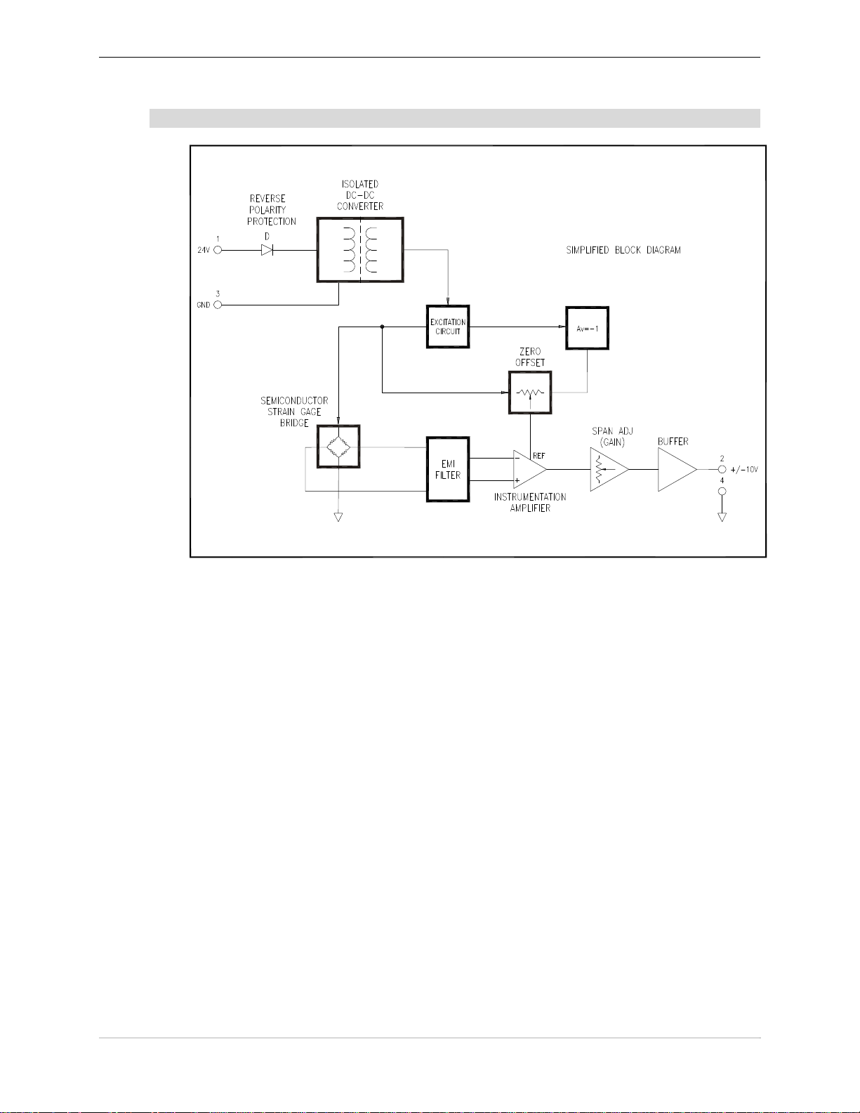
The Integrated Signal Conditioning (ISC) tension transducer has a separate ground reference
(common) for the output signals. The ground used by the output circuits is electrically separate from
the ground return for the fixed 24Vdc supply. The 24Vdc supply inpu t is protected against reverse
polarity.
The Integrated Signal Conditioning (ISC) tension transducer uses an embedded Instrumentation
Amplifier (IA) to amplify the millivolt level signals generated by the strain gage bridge, while
effectively rejecting common-mode noise. Low drift Surface Mount Technology (SMT)
components, Multi-layer Printed Circuit Boards (PCB) and optimum circuit topologies are
incorporated to promote load cell signal integrity.
The Amplifier gain is adjustable over a 9.6:1 range to allow span calibration of the analog outputs.
A precision low voltage excitation source is provided for exciting the strain gage elements in the
internal strain-gage bridge.
The use of galvanic isolation can aid in reducing noise pickup caused by ground loops in the field
wiring and accommodates limited voltage gradients between input and output sections of the
application wiring.
PAGE 9 OF 42

ULTRA ISC SERIES SLIM CELL TRANSDUCER MAN-70434-0 REV AA
1.2 FEATURES
Ultra ISC tension transducer features are:
Factory Calibration promotes interchangeability
Tension controller observation of individual loadcell signals provides increased oppo rtunity
for advanced diagnostics and calibration.
Self contained precision excitation circuit eliminates the need for the expense and
complication of remote sense
24V supply has reverse polarity protection
Analog output buffer designed to accommodate capacitive cable loads.
Floating strain-gage and output stage allows “stacking” ISC outputs for simple summing.
Sealed enclosure and M12 connector provide environmental protection
Industry standard M12 allows use of readily available molded cordsets
1.3 HOW IS THE ULTRA ISC USED
The Ultra ISC load cell has been developed for those customers who desire to send the amplified
transducer signal directly into their Controller, PLC, PAC, Drive, or Local I/O.
The signal outputs are zeroed, scaled, and summed (if a pair of transducers is used) by
software. It is the responsibility of the customer to write this software.
The Ultra ISC load cell is shipped preset from CMC with 0 volts representing no load, and 10 volts
representing the 100% full rating of the transducer. (Example: A 100 lb Ultra ISC transducer with no
load outputs 0 volts. With a 100 lb. load the output is 10VDC when loaded in one direction and 10VDC when loaded in the opposite direction.)
1.4 CE EMC RESPONSIBILITY
The Integrated Signal Conditioning (ISC) Amplifier MO-13333-10ISC Ultra Series module
embedded in the transducer can be considered a component performing a direct function and
therefore is subject to the provisions of the EMC Directive.
To assist manufacturers, suppliers, and installers of relevant apparatus, this amplifier module is
compliant to EN61326:1997 when installed according to these instructions. Manufacturers,
suppliers, and installers of relevant apparatus may use this compliance as a contributing basis for
their own justification of overall compliance with the EMC Directive.
Before installing the Ultra Series ISC Amplifier you must clearly understand who is legally
responsible for conformance with the EMC Directive. Misappropriation of the CE mark is a criminal
offense.
PAGE 10 OF 42

MAN-70434-0 REV AA ULTRA ISC SERIES SLIM CELL TRANSDUCER
1.5 GENERAL SPECIFICATIONS
Item Specification Comments
Input Supply
Power Supply Requirements 21.6-26.4 VDC @ 50mA Basic Isolated Amplifier
Load Cell (Transducer)
Transducer Excitation (Vexc) 3.0 VDC FIXED Internally supplied.
Amplifier
Calibration Range Min. 0.9 - Max. 9 Multi-turn Gain adjustment provided.
Zero Adjustment Output Zero Preset at CMC – Accessible
by user if absolutely necessary
Span (Gain) Adjustment Preset at CMC – Accessible by user if
absolutely necessary
Amplifier Output Signal +/-10 VDC @ 2 mA
Isolation
Isolation +/- 50 V max. output circuit potential not to exceed
0V=Zero force on beam
Adjustments provided
+/-10 is undamped signal
50 V from protective earth potential
1.6 PHYSICAL SPECIFICATIONS
Item Specification Comments
Integrated Signal Conditioning mountable
Enclosure Type
Enclosure Size
Weight – Basic Amplifier 50 Grams 2.5 ounces
Connector 4 Pin M12 Quick-connect M12 Quick-connect 4 Pin, DC Keyed
with special adjustments accessible from
the surface. Remove sticker or screw to
access the setup potentiometers.
Base: 26 mm wide by 26 mm high
length:43 mm
Aluminum enclosure just behind the
M12 connector.
1.0 inches (width) by 1.0 inches
(height) 1.7 inches (depth)
1.7 ENVIRONMENTAL REQUIREMENTS
Requirement Description
Enclosure
Operating temperature
Humidity
Altitude
Atmosphere
Storage temperature range
Transport temperature range
IP65
0 to 70 degrees C
32 to 158 degrees F
Non-condensing
85% at 55 degrees C
85% at 132 degrees F
1000 meters
3300 feet
Non-flammable, non-corrosive and dust free
-30 to 90 degrees C
-22 to 194 degrees F
-40 to 80 degrees C
-40 to 176 degrees F
PAGE 11 OF 42

ULTRA ISC SERIES SLIM CELL TRANSDUCER MAN-70434-0 REV AA
1.8 OPERATING CONDITIONS
Condition Isolated Signal Conditioning Amplifier
Installation category Category III
Pollution Pollution Degree 2
Input supply Earth (Ground) referenced
Protection Enclosure mounted
1.9 EMC TECHNICAL RATINGS
Port Phenomenon Test Standard Level From Test Standard
Enclosure ESD EN 61000-4-2: 8KV AD, 1KV CD EN 61326:1997
Enclosure RF Field EN 61000-4-3 10V/m,1 Khz AM EN 61326:1997
Output Leads
DC Supply
Leads
DC Supply
Leads
Output Leads
Fast
Transient
Burst
Fast
Transient
Burst
Conducted
Immunity
Conducted
Immunity
EN 61000-4-4 1kV EN 61326:1997
EN 61000-4-4 1kV EN 61326:1997
EN 61000-4-6 3V/m EN 61326:1997
EN 61000-4-6 3V/m EN 61326:1997
1.10 EMISSION SPECIFICATIONS
Port Phenomenon Test Standard Level Generic Standard
Enclosure Radiated EN 61326:
The levels of performance indicated are achieved when the Isolated Signal Conditioning Amplifier is
installed by using the instructions and specifications outlined in this document.
1997
Class A EN 61326:1997
1.11 SPECIFICATIONS
Item: Specification:
Slim Cell 1 Slim Cell 2
Transducer Weight
Weight + Bracket
Material Body and Side Plates – Stainless Steel 410
Bridge Resistance 135-147 Ohms @ 20
2.8 lbs.
1.3 kg
Slim Cell 1 Slim Cell 2
5.5 lbs.
2.5 kg.
o
6.6 lb.
3.0 kg.
11.6 lb.
5.3 kg.
C
Gage Type Semi-conductor strain gage, gage factor equals 95 (nominal)
Excitation Voltage 5.6 VDC maximum
Nominal Output Signal at Rated
MWF
(Excess voltage can cause permanent damage)
+/- 100 mV per Transducer (with 5 VDC excitation voltage)
PAGE 12 OF 42

MAN-70434-0 REV AA ULTRA ISC SERIES SLIM CELL TRANSDUCER
Output Impedance Approximately 64 Ohms per Bridge leg
Maximum Voltage, Gage to
Beam or Base (Ground)
Operating Temperature Range 0o F to +200 o F
Maximum RPM 2500 (without derating)
Alignment +/- 2 degrees angular displacement
Break-away torque 0.6 lb-in
1.12 SLIM CELL FORCE RATINGS
Size MWF (lb.) Linear Overload (%)* Ultimate Overload (%) **
10 400 800
25 400 800
UltraSlim 1
UltraSlim 2
*Linear overload: Maximum force applied on the transducer before hitting the safety stop (the output is linear up to that
point).
** Ultimate Overload: Maximum force applied on the transducer with out risking permanent deformation.
50 400 1000
100 300 1000
250 300 1000
500 150 500
500 200 1000
1000 150 500
50 Volts peak
PAGE 13 OF 42
ULTRA ISC SERIES SLIM CELL TRANSDUCER MAN-70434-0 REV AA
1.13 BLOCK DIAGRAM OF ULTRA SERIES ISC AMPLIFIER MODULE
Figure 2 Block Diagram of Ultra Series ISC Amplifier Module
PAGE 14 OF 42

MAN-70434-0 REV AA ULTRA ISC SERIES SLIM CELL TRANSDUCER
2 PRODUCT COMPONENTS
The Ultra Series ISC Slim Cell Tension Transducer (see Figure 3) consists of a housing that
contains the amplifier and power supply boards that are coupled directly to an “Ultra” type load
cell. There is an M12 connector to send amplified transducer signals into a tension controller,
PLC, PAC, drive or local I/O. This housing has two access holes for gain and zero potentiometer
adjustments if necessary.
Figure 3 Ultra Series ISC Slim Cell Tension Transducer
PAGE 15 OF 42

ULTRA ISC SERIES SLIM CELL TRANSDUCER MAN-70434-0 REV AA
2.1 M12 MATING CONNECTOR
The M12 connector used on the Ultra Series ISC amplifier is a four-pin, DC keyed, male
connector that mates directly with the molded cordset offered by Cleveland Motion Controls.
col
Table A lists the pin numbers, signal, function, wire
When mating the connector, align the keying
mechanism and pins so that they enter the socket
without you having to apply excessive force. Use
your fingers to sufficiently tighten the coupling nut
enough to ensure an adequate seal and to
discourage accidental loosening.
ors and any notes that apply:
Figure 4 - Front View of M12 Connector
Supply
1 24 VDC
2 +/- 10V OUT
3 0V RET Power Supply Return Blue Must not exceed 25 volts from P.E.
4 COMMON Output signal Return Black
Signal Function
Power Supply source 24
Vdc
Voltage Signal Output
Undamped bi-polar tension
signal
If you choose to make your own cables or need to repair damaged connectors, you can purchase a separate
mating connector from Cleveland Motion Controls. To order, use CMC part number, X43-34338.
A fuse with a rating of 0.25A must be used in the fixed 24 VDC supply lead to limit potential damage to the
amplifier in the event of circuit malfunction. Example: Bussman GMA-250-R
Transducers (load cells) use strain gages which have limited insulation levels to ground (earth). This requires that
the COM terminals be referenced to ground (earth) to prevent damage to the transducers (load cells).
Table A M12 Connector Pin #s and Signals
Wire
Color
Brown
White max. load 2 mA
+24 VDC
@ 35 mA max
Common for +/- 10V an analog output
Must not exceed 25 volts from P.E.
Notes
PAGE 16 OF 42

MAN-70434-0 REV AA ULTRA ISC SERIES SLIM CELL TRANSDUCER
2.2 ELECTRICAL CONNECTIONS AND WIRING
Refer to Figure 5 for making the transducer to power supply and tension controller connections.
Make certain that:
The cables do not interfere with the web path, and that they are away from power
transmission gearing or other moving part s.
You exercise care when routing the cables to avoid pick-up from noise-radiating power
cabling (motor armature leads, AC main wiring, etc).
In environments with severe electromagnetic noise, it may be necessary to route the
cables inside metallic conduit.
Polarity changes are accommodated by reversing the physical orientation of the
transducer, by interchanging the black and white output wires or by changing the settings
in the user’s application software.
Figure 5 Installation Wiring Diagram
PAGE 17 OF 42

ULTRA ISC SERIES SLIM CELL TRANSDUCER MAN-70434-0 REV AA
2.3 CABLING
Important: Most start-up problems are the result of mis-wiring or failure to reference the detailed
information in this manual. Additional information details can be found in the subsequent sections of this
manual and should be referenced before actual installat i on begins.
The connector for the ISC is a standard 4-pin M12 quick-connect connector keyed for DC operation.
Molded cordsets are readily available (see Table B) that can provide a direct conn
equipped Tension Transducer, the required 24 VDC sup ply and tension controller (PLC, Tension Indicator,
Analog Input Module, etc). Ready-made PUR (polyurethane) jacketed cordsets are available in different
lengths and different connector orientation (straight or right-angle) from Cleveland-Motion Controls. It is
advisable to employ an overall outer shield (or place cable in a metallic conduit) for noise rejection in
environments with high levels of electromagnetic interference.
The wire gage should be a minimum of 24 AWG to aid in minim i zi ng un desi rable voltage drops. An
overall outer shield is required, with the shield connected to ground at the tension controller through as
short a connection as possible. The short connection is essential in minimizing parasitic inductance and
thereby maximizing the shielding effectiveness at high frequencies.
Exercise care in routing the cable to minimize electromagnetic interference from noise generating wiring
and equipment.
ailable cordsets (Get from Web marketing):
Table B lists the part numbers and descriptions for these a
v
ection between the ISC
Length
Cordset Part
Number
Connector
Orientation
Cordset Part
Number
Connector
Orientation
3M X44-33975-010 Straight X44-33976-010 Right-Angle
8M X44-33975-026 Straight X44-33976-026 Right-Angle
16M X44-33975-052 Straight X44-33976-052 Right-Angle
24M X44-33975-078 Straight X44-33976-070 Right-Angle
32M X44-33975-105 Straight X44-33976-105 Right-Angle
48M X44-33975-157 Straight X44-33976-157 Right-Angle
Table B Cordset Part Numbers
PAGE 18 OF 42

MAN-70434-0 REV AA ULTRA ISC SERIES SLIM CELL TRANSDUCER
2.4 POWER SUPPLY REQUIREMENTS
For best performance, a regulated DC power supply that provides a nominal 24 VDC and at least 50 mA per
ISC should be used.
Important: Pay particular attention to the power supply for susceptibility to the effects of condu c ted and
radiated energy from noise sources. Every effort should be made to provide stable voltage to the amplifier
using correct wiring practices and filters. To protect against circuit damage, include a 0.25 Amp fuse in the
power supply output lead to each amplifier in case of amplifier or power supply malfunction.
The power source for the power supply shall be fused at the proper rating to prevent over current in
the supply leads due to a power supply failure.
Output voltage from the supply should be within +/- 10% of 24 VDC. Component stress due to excessive
supply voltage may damage components and prolonged operation with a higher than necessary voltage will
increase the internal temperature of the circuitry within the ISC. Supply voltages that are excessively low (
either due to a low supply set-point or excessive IR drop of voltage arising by long cable runs ) can result in
“brown-out” of internal regulated supply voltages. This “brown-out” may be evident by the +/- 10V analog
output being clipped at some voltage below 10V. Keep in mind that voltage drops due to long cable runs
may drop the voltage by nearly a half a Volt (250 feet of 24 AWG cable carrying 30 mA will loose 0.4 V).
Although the amplifier provides limited galvanic isolation between the 24 VDC supply circuit and the straingage amplifier circuit, it is only intended as a mechanism to avoid “ground loop” interference. The 24 VDC
supply should always have its output return referenced to P.E. (protective earth), so that uncontrolled
potentials are not imposed between the 24 VDC supply circuit and the load cell case.
For optimum performance, the DC supply voltage should be free from excessive ripple voltage or transient
excursions.
2.4.1 INTERFACE WIRING
The load in this connection may be an indicator, recorder, data acquisition device or the analog input
terminals of a control device such as a DC drive or a programmable logic controller. The output signal at this
terminal is undamped and provides a direct response to changes in the transducer (load-cell) load. Note that
the cable’s shield drain wire should be connected at only one end, preferably at the “receiving end” (i.e.
common ground at the PLC Analog Input etc.)
The pair of wires associated with the amplified transducer signal are generally separated out from the 24VDC
supply wires at the point where they get routed toward the tension controller.
For most M12, DC keyed molded cordsets, the wire colors associated with the #1 and #3 pins is BRN and
BLU respectively.
For most M12, DC keyed molded cordsets, the wire colors associated with the #2 and #4 pins are WHT and
BLK respectively. These WHT and BLK wires provide the amplified tension signal transmitted as a +/- 10
VDC Full.Scale. analog signal from an internal op-amp (operational amplifier) buffer stage. The BLK wire
has the signal return and the WHT wire is the amplifier output. Resistive loads drawing up to 5 mA of
current are allowable.
The most common way of reversing the sense of the load cell signal is to invert the mechanical orientation of
the loadcell body itself. If this is impractical, it is possible to interchange the BLK and WHT signal wires, as
the loadcell amplifier and output stage is essentially floating with respect to the 24 VDC supply ground. Note
however that the voltage potential cannot be allowed to float “unbounded”, and that connection to line
potential drive circuits is not permissible (and potentially hazardous).
PAGE 19 OF 42

ULTRA ISC SERIES SLIM CELL TRANSDUCER MAN-70434-0 REV AA
2.5 POTENTIOMETERS ADJUSTMENTS (IF NEEDED)
The gain and zero adjustments are factory preset but accessible by the user for adjustment if
absolutely necessary. Adjustment holes to access these potentiometers are visible on the side of the housing.
Adjustments can be made by removing the sticker around the amplifier enclosure. Use Figure 3 to locate the
an
d gain adjustment holes
zero
The Table C lists these potentiometers, their reference designator, and a description of their functions. For
info
rmation on the correct adjustment tool to use, refer to section 2.5.1 in this document.
Potentiometer
GAIN P2
ZERO P1
Reference
Designator
Function
This potentiometer is preset but accessible by the user for adjustment if
absolutely necessary. It provides a 10:1 “vernier” adjustment of the amplifier
gain. It is a multi-turn potentiometer, with clockwise rotation causing an
increase in amplifier gain. When turned fully counter clockwise, the
potentiometer causes the amplifier stage to provide the minimum gain.
This potentiometer is preset but accessible by the user for adjustment if
absolutely necessary. It provides a zero (offset) adjustment. It is a multiturn potentiometer, with clockwise rotation causing a positive shift in the
analog outputs. It should be set mid-way prior to setting the ZERO
adjustment.
Table C Potentiometers Adjustments
2.5.1 CORRECT ADJUSTMENT TOOLS
A small flat-bladed “jeweler’s” screwdriver is required. The overall diameter should be no larger than 0.062”
The thickness of the blade flat should be no greater than 0.012”. Ideally, a non-conductive tool (plastic or
ceramic) provides the safest approach for minimizing the generation of minute metallic shards that are made
when a metal blade accidentally scuffs the aluminum housing.
The Zero is normally adjusted first while the loadcell is in the No-Load condition (i.e. with no tension in the
web). The calibration forces are then applied to the transducer and then the gain potentiometer adjusted to
achieve the desired scale factor. It is advisable to look for a particular step change between load and no-load
conditions and adjust the step size independent of a particular zero point. Only after the desired scale factor
is achieved, is it then best to adjust the final zero point using the Zero adjustment.
Following adjustment, it is important to seal the adjustment holes for continued protection from
contamination. A small piece of adhesive backed tape can be used to reseal.
PAGE 20 OF 42

MAN-70434-0 REV AA ULTRA ISC SERIES SLIM CELL TRANSDUCER
3 PRODUCT APPLICATION
The Ultra Series Slim Cell Transducer utilizes a twin sensing beam. Conversion from mechanical
strain to an electrical signal is accomplished using semiconductor-based, piezoresistive strain gage
elements. The Full Wheatstone Bridge configuration provides an electrically balanced output
yielding twice the amount of signal swing as half-bridged transducers operated at the same
excitation voltage. Integral span compensation is used to correct for temperature induced gain
changes.
MACHINE FRAME
SLIM CELL TRANSDUCERS
Figure 6- Slim Cell Transducer Incorporating Shaft Bearing Function
Slim Cell Transducers can be used with either rotating (live) shaft rolls (RS type) or, stationary
(dead) shaft rolls (SS type) that incorporate their own low friction bearings. For more information
on transducer type selection refer to Section 4.2.5 .
t
The Ul
ra ISC has been developed for those customers who desire to send the transducer signal
directly into their Controller, PLC, PAC, Drive, or Local I/O. When a pair of transducers is used,
the signal outputs can be zeroed, scaled, and summed by software. It is responsibility of the
customer to write this software.
3.1 FINAL CALIBRATION
When calibration is done though application software within the target controller, the greatest
calibration accuracy is achieved though the use of individual gain and offset parameters for each
of the two transducers (which generally are used in pairs). By using separate analog inputs and
separate gain and offset parameters, you can correct for any transfer function differences arising
from subtle mounting variations intrinsic to transducer output variations. If however the loadcells
are summed first and then digitized, the matching of loadcell outputs (as affected by such things as
loadcell orientation relative to the wrap angle) becomes more critical.
The tradeoff between hardware cost and accuracy will impact the decision as to which approach
users decide to take.
PAGE 21 OF 42

ULTRA ISC SERIES SLIM CELL TRANSDUCER MAN-70434-0 REV AA
3.2 SUMMING
In the majority of applications, loadcells are used in pairs. The net tension of the web must
therefore be represented by the summation of the two loadcell signals. As described above, th e
summation can be done in software, so long as both analog channels can be independently
observed. When only a single analog input is available, some other form of summer is required.
Two simple approaches are described below.
In the most common approach, a pair of equal-valued resistors are used in the classic resistive
summer circuit. A third resistor acts as a ground referred load which receives the combined signal
from each of the loadcells. The load resistance may be part of the analog input circuit’s input
impedance, but may also be supplemented by a fixed resistance for improved load resistance
stability.
In the following schematic using the resistance values shown, the equation for the summed signal
is:
= 2/5 (V
V
sum
The resultant voltage for 10 volts applied to V
left
left
and V
+ V
)
right
would therefore be 8V.The maximum
right
load impedance experienced by each loadcell’s output stage would be 7.5K ohm, necessitating that
each loadcell amplifier be capable of 1.3 mA of load current.
Figure 7 ISC Summing Amplifier
The final approach to be discussed is to “stack” the two loadcell outputs by wiring the analog
outputs to be “series aiding”.
PAGE 22 OF 42

MAN-70434-0 REV AA ULTRA ISC SERIES SLIM CELL TRANSDUCER
3.3 SUMMING BY “SERIES STACKING”
The final interface approach to be discussed is to “stack” the two loadcell outputs by wiring the
analog outputs to be “series aiding”. Note that with each loadcell outputs at a maximum of 5VDC,
the sum would be 10 VDC. As should be obvious, loadcell signals greater than 5 VDC each will
likely take most PLC analog inputs over-range.
Figure 8 Stacking the Two Loadcell Outputs
Here is a simple example of software scaling and summing
Command Description
Sample (digitize) LCH and store
Sample RCH and store
ADD LCH_OFSET to LCH parameter
Multiply offset corrected LCH parameter by
LCHGAIN
ADD RCH_OFSET to Digitized RCH parameter
Multiply offset corrected RCH param. by RCHGAIN
Add resultant LCH and RCH parameters
; Store digitized LCH.
; Concurrent samples are best.
; LCH_OFSET is the zero correction constant.
; This scales the Left Channel for span
; RCH_OFSET is the zero constant
; This scales the Reft Channel for span.
; This is the composite tension feedback
Note that sometimes, over-sampling and filtering can be used to generate a robust tension
feedback parameter despite brief disturbances (either mechanical or electrical).
PAGE 23 OF 42

ULTRA ISC SERIES SLIM CELL TRANSDUCER MAN-70434-0 REV AA
4 INSTALLATION
4.1 RECEIVING AND UNPACKING
After receiving the Ultra ISC Slim Cell Transducer you should:
Carefully unpack and handle the equipment
Compare the received shipment with the packing list
Report any damage to the carrier and your CMC representative
Store equipment that will not be used in a clean, dry location
Take appropriate precautions to prevent moisture, dust and dirt from accumulating in storage
and installation areas
4.2 BEFORE INSTALLING THE TRANSDUCER
Before you install the Ultra ISC Slim Cell Transducer you should perform the following steps:
Review the safety considerations (Section 4.2.1 )
Assem
R
Determ
Determ
le the mounting hardware and review the torque fastener information (Section 4.2.2 )
b
ference the mounting dimensions (Sectio n 4.2.3 )
e
e a mounting location (Section 4.2.4 )
in
ine an a
ppropriate mounting style (Section 4.2.5 )
4.2.1 SAFETY CONSIDERATIONS
Don’t let safety be an afterthought. Before installing, servicing or calibrating review and follow
applicable policies and procedures to ensure worker safety. Machinery must be in a safe state and
be aware of any additional hazards that can arise when installing and calibrating higher force
transducers.
The following points are important to remember:
When “dead-weights” are used to produce calibration forces, always wear steel-toed
shoes.
When manually handling weights, use safe lifting practices to avoid injury.
Size cordage or straps with an ample safety factor to reduce the chances of failure and
falling weights.
Consider where the cords and weights will travel should a failure occur.
Check that all hardware is mounted with appropriate fasteners (thread size and pitch,
fastener grade, length of thread engagement).
PAGE 24 OF 42

MAN-70434-0 REV AA ULTRA ISC SERIES SLIM CELL TRANSDUCER
4.2.2 MOUNTING HARDWARE AND RECOMMENDED FASTENER TORQUE
UltraSlim 1: Torque:
¼ - 20 x 1-3/8 “(typical)
SAE grade 8
M6 - 1.0 x 35 mm L,
Property Class 10.9
Setscrews
10 - 32 (Inch Hub)
M5 - 0.8 (Metric Hub)
UltraSlim 2: Torque:
3/8-16 x 2 (typical)
SAE grade 8
M10 - 1.5 x 50 mm L,
Property Class 10.9
Setscrews
¼ - 20 (Inch Hub)
M6 - 1.0 (Metric Hub)
10 lb-ft
8 N-m
24 lb-in
4.7 N-m
32 lb-ft
45 N-m
7.5 lb-ft
6 N-m
Mechanisms used for industrial automation can tax even the best threaded fasteners. You can
improve the likelihood that bolts and shafts remain secure by using suitable anaerobic “thread
lockers” during the final assembly.
Trademark Information
Loctite is a registered trademark of Henkel Loctite Corp.
Kidder is a registered trademark of Cleveland Motion Controls
PAGE 25 OF 42
ULTRA ISC SERIES SLIM CELL TRANSDUCER MAN-70434-0 REV AA
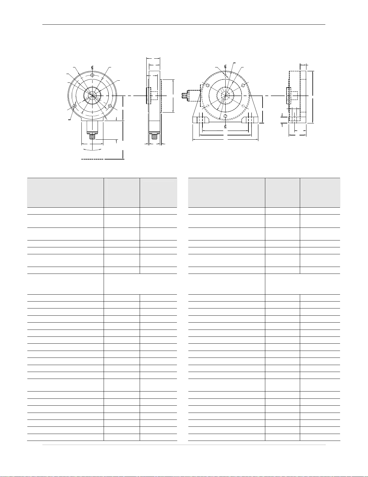
4.2.3 MOUNTING DIMENSIONS
G
A
C
E
B
D
H
N
S
RY
T
C
M (BOLT DIA)
K
62 ° OF ANGULAR ALIGNMENT
WITH BOLT IN POSI TI ON
L
AA1
OR
AA2
SLIM CELL
J
O
P
FI
Q
MOUNTING BRACKET ( WITH SLIM CELL)
Z
X (BO LT DIA)
U
Mounting Dimensions for English Hardware: Mounting Dimensions for Metric Hardware:
Designator:
A 4.50 5.80
AA1
(mating conn. at right angle)
AA2
(mating conn. straight)
B 3.75 4.75
BB 1.08 1.33
C 2.996 -
D 1.50 2.46
E 0.625 1.250
F 0.12 0.14
G 1.31 1.70
H 1.02 1.32
I 0.07 0.10
J 2.30 3.05
K 2.00 2.50
L 1.275 1.275
M .28 (3) .40 (3)
N 1.02 1.36
O 4.22 5.50
P 4.78 6.5
Q 6.00 8.00
R 3.000 -
S 4.50 5.80
T 0.55 0.65
U 0.55 0.65
V 1.60 2.1
W 4.75 6.2
X 3/8 (2) ½ (2)
Y 1/4 - 20 3/8-16
Dimension
in
Slim Cell
Transducer
1:
Dimension in
Slim Cell
Transducer
2:
1.3 1.3
2.5 2.5
4.196 -
3.000
4.200
0.750 1.500
1.000 1.750
4.200 -
3.006
4.206
Designator:
A 114.3 174.3
AA1
(mating conn. at right angle)
AA2
(mating conn. straight)
B 95.3 120.7
BB 27.4 33.8
C 76.10 -
D 38.1 62.5
E 15 30
F 3.0 3.6
G 33.3 43.2
H 25.9 33.5
I 1.8 2.5
J 58.4 77.5
K 50.8 63.5
L 32.625 32.625
M 6 (3) 8 (3)
N 25.9 34.5
O 107.2 139.7
P 121.4 165.1
Q 152.4 203.2
R 76.20 -
S 114.3 174.3
T 14.0 16.5
U 14.0 16.5
V 40.6 50.8
W 120.6 157.5
X 10 (2) 12 (2)
Y 1/4-20 3/8-16
Dimension
in
Slim Cell
Transducer
1:
33 33
64 64
76.20
20 35
25 40
76.35
W
BB
V
Dimension in
Slim Cell
Transducer 2:
106.58 -
106.68
106.68 -
106.83
PAGE 26 OF 42

MAN-70434-0 REV AA ULTRA ISC SERIES SLIM CELL TRANSDUCER
NC (3) NC (3)
Z 2.50 3.30
Table D Transducer and Mounting Bracket Dimensions
NC (6) NC (6)
Z 63.5 83.8
PAGE 27 OF 42
ULTRA ISC SERIES SLIM CELL TRANSDUCER MAN-70434-0 REV AA
4.2.4 SELECTING A MOUNTING LOCATION
Select the mounting location for the transducer keeping the following points in mind:
The transducer can be mounted to either inside or outside of the machine frame.
The tension-sensing roll must not be mounted where the web wrap angle can vary, or the
transducer will not interpret the tension properly as the angle varies. If a variance in the
wrap angle occurs, it is sensed by the transducer as a tension change and the change is
indicated on the tension indicator. In cases where it is impossible to mount the transducer
where the wrap angle does not vary, the change in indicated tension that results should be
calculated and if small, can be disregarded.
WRAP VARIESWRAP VARIES
PROCESS
OK FOR TENSION SENSING
Figure 9 Example of Varying Wrap Angles
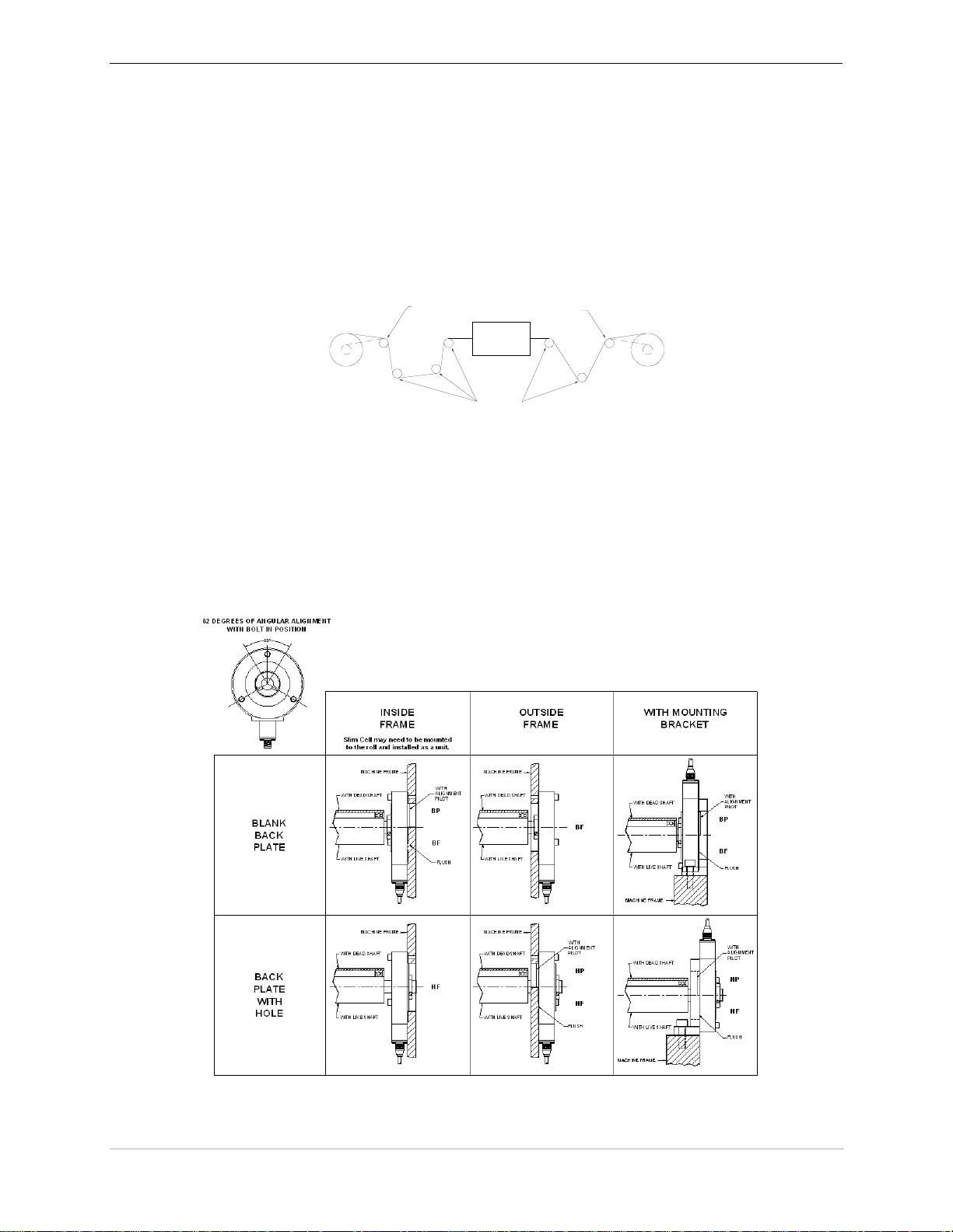
4.2.5 DETERMINE A MOUNTING STYLE
The Ultra ISC Slim Cell Transducer can be mounted in several different ways (Figure 10). When
choosing a mounting style, evaluate your options by taking the following points into consid eration:
Safety
Machine Frame orientation
Ease of Assembly
Figure 10- Slim Cell Transducer Mounting Styles
PAGE 28 OF 42

MAN-70434-0 REV AA ULTRA ISC SERIES SLIM CELL TRANSDUCER
4.3 PRE-INSTALLATION PRECAUTIONS
4.3.1 SHIPPING
Shock and vibration transmitted to the transducers by the sensing roll during transportation can
damage the transducers. It is essential that you remove the sensing roll when the machine is
shipped with the transducers mounted.
4.3.2 ROLL BALANCE
The sensing roll must be adequately balanced. Understand that the balance of the sensing roll will
be more demanding than that typically needed in general rotating machinery. The goal goes
beyond just limiting the force to which bearings will be subjected, but rather to minimize the
generation of an unintended noise component in the transducer tension signal. The centrifugal
force caused by imbalance can be estimated using the following formula:
-6
F = (1.77 x 10
Where:
F = centrifugal force (in units of lb-f)
W = weight imbalance (in units of ounces)
R = radius of displacement, distance of imbalance weight from roll axis of rotation (in inches)
RPM = Revolution per minute
The force increase is equal to the square of the RPM or in other words, doubling the RPM causes
four times the imbalance force. Because rolls tend to have a high length-to-diameter ratio, twoplane (dynamic) balancing is recommended. Balancing is particularly needed where higher RPMs
and lower web forces are involved.
) x W x R x (RPM)2
To illustrate how much imbalance induced “noise” could be generated, Table E shows the force
di
sturbance for various ISO balance grades for an illustrative case of a 20 pound roll (4” diameter
x 36” long, aluminum ) rotating at 1500 RPM.
Table E Force Disturbance For Various ISO Balance Grades
Balance Grade
(ISO 1940/1):
G16 1.25 oz-in +/- 5 lb-f at 25 Hz
G6.3 0.5 oz-in +/- 2 lb-f at 25 Hz
G2.5 0.2 oz-in +/- 0.8 lb-f at 25 Hz
G1 0.08 oz-in +/- 0.3 lb-f at 25 Hz
4.3.3 CRITICAL ROLL SPEED
Even with a balanced roll, a vibration can be set up in a stationary shaft. If this vibration (in cycles
per minute) occurs at the harmonic frequency of the shaft, the transducers can be damaged. To
determine the critical roll speed, use the following formula:
Critical roll speed in RPM = 4.8 x 10⁶ x Shaft O.D.
(Shaft Length)
(Dimensions are in inches)
To assure that this issue is avoided, the critical roll speed should be at least 20% above the roll
speed attained at maximum web speed.
Residual Imbalance:
Resultant Force due to
Residual Imbalance:
2
4.3.4 AVOIDING DAMAGE TO THE TRANSDUCERS
To avoid damaging the transducers, refrain from repetitive overloading above the maximum
working force or severe overloading.
PAGE 29 OF 42

ULTRA ISC SERIES SLIM CELL TRANSDUCER MAN-70434-0 REV AA
4.4 INSTALLATION PRECAUTIONS
To ensure proper installation and operation of the system, keep the following points in mind:
Do not apply shock loads to the Slim Cell bearing assembly when mounting or
dismounting rolls.
Exercise care to avoid overstressing the transducer when handling partially mounted rolls.
Even relatively short rolls can afford an impressive mechanical advantage over the
sensitive transducer.
Bolting the transducer to a non-flat surface can cause deformation of the transducer body
and degrade the quality of the tension signal.
Failure to follow these precautions can result in serious damage to the Slim Cell Transducers and
possibly void the warranty!
4.5 MOUNTING THE SLIM CELL TRANSDUCER TO THE MACHINE FRAME
The Slim Cell Transducer can be mounted directly to the machine frame or mounted using the optional
mounting bracket.
The mounting surfaces for the Slim Cell Transducer should be flat and parallel to each other. Remove any
loose paint, rust or scale from the machine frame before mounting.
When Mounting the Slim Cell Transducer Directly to
the Machine Frame:
The Slim Cell can be mounted on either
the inside or outside of the machine
frame. Refer to Figure 10 to help
eterm
ine the arrangement that best suits
d
your application.
Before drilling and tapping the mounting
holes in the machine frame, refer to
section 4.6 to ensure proper alignment of
e Slim
th
Cell.
Mount the Slim Cell Transducer into
place with three bolts. For properly
positioned bolt hole centers and sizes,
refer to the dimensions listed for letters B
and M in Error! Reference source not
found.. The bolt hole centers are evenly
spaced on a circle and 120 degrees from
each other.
When Mounting the Bracket to the Machine Frame:
The transducers can be mounted on either
side of the bracket. Refer to Figure 10 to
p
determine the arrangement that best
hel
suits your application.
Drill and tap two mounting holes in the
machine frame for each bracket. Refer to
dimension X, O and P in Table D for
r
ect dimensions for the bolt holes.
cor
PAGE 30 OF 42

MAN-70434-0 REV AA ULTRA ISC SERIES SLIM CELL TRANSDUCER
4.6 POSITIONING THE SLIM CELL TRANSDUCER
Use the following steps when positioning the transducers for mounting:
1. Before bolting the transducer in place, be sure that it is generally aligned with the tension force (load
direction). The transducer is properly aligned when the load direction (bisector of the wrap angle) is
pointing along a line connecting the “+” and “-“signs located on the sides of the load cell
2 Insert and finger-tighten the bolts.
3 Rotate the slim cell outer ring so that the load direction is precisely aligned with the “+/-“ axis. the outer
ring can be rotated 60 degrees in either direction to achieve the proper alignment position.
4 Tighten the mounting bolts to the recommended torque (refer to section 4.2.2 ). It is a good practice to
tighten e
5 Note the alignment of the force. If the force points to the “+” sign, the output signal of the transducer is
positive. If the force points to the “-“ sign, the output is negative. This information is important to know
when wiring the transducer to the indicator or controller terminals. Interchanging the black wire and
white wire at the amplifier terminals (connections) may be required to provide the proper signal polarity
for the device.
ach bolt increm
entally, and in succession.
Figure 11 – Positioning the Slim Cell Transducers for Mounting
PAGE 31 OF 42

ULTRA ISC SERIES SLIM CELL TRANSDUCER MAN-70434-0 REV AA
4.7 MOUNTING THE SENSING ROLL
Be sure to exercise care during this portion of the installation, as it easy to produce excessive force on the
transducer sensing beams. To mount the roll, use the following steps:
1. Loo sely fit the roll into the transducer to verify that the shaft and the adapter fit without excessive
interference or clearance. For reference, the bore diameter of the hub is +0.0007 and +0.0017 in.
(+0.018 and +0.043 mm) from the nominal diameters listed in Section 4.2.3 .
2 Che
3 Secure o
4 Tighten the set screws while preloading the hub.
ck to see if the transducer has a blank back plate (without a hole). If it is a blank plate, be sure that
the roll shaft does not extend too deep inside of the Load Cell and rub against the back plate. Refer to
letter N in Section 4.2.3 of this document.
ne end of the roll shaft into either of the Slim Cell Transducer shaft hubs by tightening the two
set screws.
Preloading of the adapter shaft hub allows for expansion and contraction of the roll shaft. Because of
the affects of thermal gradients and differing material, both expansion and contraction must be
accommodated.
To preload the hub, push the hub inward against the resistance of the internal spring prior to tightening
the set screw on the remaining shaft hub.
During final assembly, you can use Loctite® #609 retaining compound on the roll journal to
transducer hub interface, and Loctite’s #242 (removable strength) thread locker on the set screws.
4.8 CHECKING THE TRANSDUCER MOUNTING
Before preparing to apply force to the transducer(s) and calibrating th e amplifier, inspect the load cell to
confirm that it is oriented and mounted in accordance to the installation instructions. Common problems
include:
Failure to mount transducers on flat (machined) surface.
Poor shaft alignment that exceeds allowable limits.
Fastener torque either excessive or insufficient.
Transducer mis-oriented so that the axis of sensing is not true to the applied force vector
(bisector of the wrap angle).
Roll is mounted without allowance for shaft expansion/contraction at transducer hub.
The transducer is positioned in the web path so that the wrap angle is not constant.
PAGE 32 OF 42

MAN-70434-0 REV AA ULTRA ISC SERIES SLIM CELL TRANSDUCER
4.9 POWER-UP AND TESTING
4.9.1 BEFORE APPLYING POWER
Before applying power, check the wiring to the amplifier. Pay particular attention to the following:
Double check the transducer cabling to ensu re that th e 24V power supply is within limits
4.9.2 POWER APPLICATION
and polarity is correct.
Use an approved anti-static wrist strap when adjusting any potentiometers on the amplifier.
Use the appropriate tool when making any adjustments to the potentiometers on the
amplifier. Damage to the circuitry may occur if excessive force is used or a conductive tool
accidentally contacts internal voltages.
As soon as practical after connecting power to the ISC, verify that the 24 VDC supply is
operational and not overloaded by any mis-wiri n g.
polarity is correct and that the voltage is within the prescribed limits. Promptly identifying any
over-voltage condition can help minimize potential damage to the circuitry internal to the
transducer.
With 24 VDC supply confirmed, check the DC output voltage reported by the ISC and see if it
responds as expected when small test forces are applied to the Tension Transducer.
Use a DC voltmeter to confirm that the supply
PAGE 33 OF 42

ULTRA ISC SERIES SLIM CELL TRANSDUCER MAN-70434-0 REV AA
4.10 ADJUSTMENT TOOLS (ONLY IF NOT USING NUMERICAL CORRECTION)
Using the correct tools simplifies the setup process and necessary adjustments. Keep the following
points in mind:
The Integrated Signal Conditioning Amplifier utilizes two different potentiometers. The
Gain and Zero adjustments are located on the side of the amplifier (under the sticker).
The adjustment tool should have dimension on the order of 0.5mm (.020 inches) blade
thickness and be 2.5 mm wide (0.1inches).
Important: Use a non-conductive tool to alter potentiometer positions. Be sure that
adjustment tool does not touch any part of PCB circuit to avoid accidentally damaging it.
4.11 GAIN AND ZERO CALIBRATION
The gain and zero adjustments are preset but accessible by the user for adjustment if
absolutely necessary. To make your final calibration adjustments, use the following steps:
1. Verify Zero on the analog Outputs for the “unloaded” (no web force applied) condition and
adjust the Zero potentiometer to correct for any minor offset voltage.
2. Apply the calibration force to the transducer(s) and adjust the Gain potentiometer to
achieve the desired span.
3. Verify linear operation of the transducer and amplifier by applying a series of forces that
falls somewhere between the zero and full-scale endpoints. The intent is not to re-execute
any calibration per se, but to confirm the hardware’s ability to accurately report a measured
force without non-linearity.
We recommend that you focus only on achieving a particular voltage “span” between the load and
unloaded forces by alternating between the two force levels. Avoid repeatedly adjust the Zero
potentiometer between measurements unless the offset voltage becomes excessive and interferes
with achieving a valid output signal on the analog output. You should only adjust the final Zero
after the desired Gain setting has been achieved.
These final calibration steps represent the minimal adjustments that might be required at
periodic calibration intervals and
accessible through the small holes in the front cover.
typically involve only the Zero and Gain potentiometers
PAGE 34 OF 42

MAN-70434-0 REV AA ULTRA ISC SERIES SLIM CELL TRANSDUCER
4.12 PROPER PRACTICES FOR APPLYING CALIBRATION FORCES
Seldom is a transducer oriented such that the calibration can be done by simply hanging a true
dead weight from the roll. By generating a tension force that follows the same web path across the
roll, you avoid the necessity of making manual (numerical) calculations to correct for the details of
different wrap angle, transducer orientat i o n, et c.
The following diagrams show the correct and incorrect techniques to use when applying
calibration forces.
Examples of Inaccurate Wrap Angles
In this example, there was a disregard for maintaining the
correct wrap angle. The dotted line indicates the proper
web path.
Example of Correct Wrap angles and Anchor Point
In this example, the anchor point and the wrap angle have
been correctly achieved and closely follow the actual web
path.
In this example, the true web path was difficult to access
and an incorrect path was implemented using a
convenient, but incorrect anchor point.
PAGE 35 OF 42

ULTRA ISC SERIES SLIM CELL TRANSDUCER MAN-70434-0 REV AA
Examples of Force Loss due to Friction at Driven Roll
In this example, only a fraction of the test force is
transferred to the transducer due to drag from the
driven roll.
4.13 CALIBRATION ACCURACY CONSIDERATIONS
The application of an accurate calibration force requires careful attention to minimizing the nonideal effects of the real world. Keep the following points in mind:
When conducting a calibration that involves a large mass, it is often practical to use a series of smaller masses
added in succession. Consider performing an initial Zero and Gain adjustment when the first 20% of the
weights have been applied. By performing the calibration using this method, the Zero and Gain adjustments
can be made approximately correct earlier in the calibration effort (before many weights have been handled).
When the full calibration load is applied, there is a better chance that only minor adjustments will be needed.
Allow the transducer and amplifier to reach thermal equilibrium before conducting
calibration. Ideally, the temperature should reflect the expected operating cond itions.
The test force should be a moderate percentage of the intended working force of the
transducer and never over the 100% Maximum Working Force (MWF) or, you risk
calibrating with an overloaded (“clipped”) transducer signal.
Cycle the load on the transducer a number of times with the test force to pre-condition or
“set” the transducer prior to calibration. Repeat this procedure again before calibrating if
the transducer has been disturbed (i.e. roll remounted or any mounting bolts re-torqued).
With very low force transducers consider that connecting a test mass involves some finite
cord mass.
When two transducers support a roll, calibrate with the cord in the exact center of the roll.
Passing a cord over a roll on its way to the transducer inevitably causes some amount of
friction. The worst case scenario involves passing the working part of a cord over a roll
that doesn’t readily freewheel. A test was conducted to determine the loss on a stationary
4” diameter anodized roll with a 90 degree wrap angle. It exhibited a 25 to 30% loss in
force due to friction!
When all else is done correctly, the largest remaining contributor to error is friction. If
friction cannot be reduced, consider determining the magnitude of the friction through
measurement and then making first order corrections numerically.
In this example, by rearranging the anchor point
and the force location as well as utilizing the idle
roll, the frictional losses are minimized.
PAGE 36 OF 42

MAN-70434-0 REV AA ULTRA ISC SERIES SLIM CELL TRANSDUCER
Always apply and remove the test load in a continuously increasing or decreasing
manner, so that the force changes are monotonic. This helps to avoid disturbing any
hysteresis component of the transducers force signal.
When calibrating for a particularly wide roll that will always have a narrower product
tracking to one side, consider applying the calibration force at the roll position that
represents the center of the product. This will automatically cancel some of the affects of
transducer gain imbalance without the need to actually re-balance the transducers gains
within the amplifier.
It is a good practice to verify linear operation of the transducer and amplifier by applying
a final test force that falls somewhere between the zero and full-scale endpoints. The
intent is not to conduct calibration, but to confirm the hardware’s ability to accurately
report a measured force.
4.14 FINAL CALIBRATION
Even though the ISC transducer is factory calibrated, calibration is still usually required to
accommodate application variables such as wrap angle and transducer orientation. The customer
then accesses these software parameters using an HMI, keypad, or other device. The transducer is
still calibrated using weights as is done currently.
Final calibration is usually required to take in to account particular application circumstances of
roll weight, wrap angle and loadcell orientation. The final zero and span calibration is most easily
accomplished by numerical scaling within the digital processor of the tension controller. Because
each ISC equipped tension transducer has been factory adjusted for uniform transfer function,
loadcell inter-changeability when calibrated this way is readily promoted.
Field calibration still consists of applying known force conditions in the web, but instead of
adjusting a potentiometer, the observed loadcell offset is determined at the controller and then
numerically subtracted from the reported loadcell signal.
In the case of Span calibration, a known web force (equal to a moderate portion of the expected
operational force) is applied using test cords routed through the expected web path past the
transducer pair. An appropriate numerical scaling factor is then determined and used as a scaling
factor within the tension controller.
Hint
An interesting approach to slightly attenuating the loadcell output by purely mechanical means can
be used with those loadcell styles which accommodate slight rotation relative to the bisector of the
wrap angle (i.e. Cartridge transducers and Slim Cells).
Consider taking advantage of the Cosine relationship (noting that a 10 degree mechanical shift
will reduce the output span by 1.5%). The deflection of CMC’s strain gage based loadcell is
sufficiently small that tracking will not usually be adversely affected.
PAGE 37 OF 42

ULTRA ISC SERIES SLIM CELL TRANSDUCER MAN-70434-0 REV AA
4.15 EMC CONNECTIONS AND INSTALLATION
Compliance with the specified EMC directive for immunity in a heavy industrial environment and
emissions in a light industrial environment requires correct installation and wiring of the Ultra ISC
Tension Transducer. The most important precaution to be taken in the wiring is to use double
screened (shields) cabling for the cables from the transducers (load-cells) to the controller, and
from the 24VDC Power Supply to the transducer load. The outer screen of each cable must be
firmly bonded to the enclosure that contains the amplifier, the transducer (load-cell) housing and
the enclosure of the output load device. Large loops of unshielded cables must be avoided and
effective cable glands providing 360 degree grounding of the outer screen of the transducer and
output cables to the enclosure must be used.
Figure 12 EMC Connections and Installation
PAGE 38 OF 42

MAN-70434-0 REV AA ULTRA ISC SERIES SLIM CELL TRANSDUCER
4.16 CABLE GLANDS
Several manufacturers provide cable glands that can be used to ensure the integrity of the EMC
requirements when installing this equipment in the enclosure. The objective of the cable gland is
to provide a good mechanical entry into the enclosure to protect the cable and also provide an
electrical bond the outer shield (screen) of the cable to the enclosure.
The following is a list of cable gland venders and the range of cable sizes that each vender can
provide. This is not an endorsement or promotion of any particular vender or manufacturer; the
information is provided only to assist you in the application of the product described in this
document.
Cable Gland Vendor Cables
EMI-Proof Grounded Nickel Plated Brass Liquid Tight
Sealcon
14853 E. Hinsdale Ave., Suite D
Englewood, CO 80112, U.S.A.
Tel: (303)699-1135 Fax: (303)680-5344
Tel: (800)456-9012
GlobTek, Inc.
186 Veterans Drive
Northvale, NJ 07647
Tel: (207)784-1000 Fax: (210)784-0111
Email: globtek1@idt.net
URL: www.globtek.com
Wiedmuller
Tel: (800)849-9343 Fax: (800)794-0252
Belden
Strain Relief Fittings
Standard and Feed-through types
Cable diameters from 0.11 inches to 1.38 inches
Metric (PG) or NPT thread types
Optional metric (PG) to NPT adapters
Standard, IP68 protection
Index EMC Cable Glands
Cable diameters from 6.0 mm to 20.0 mm
Metric threads
Bulkhead Cable Glands for Braid/Armour Termination
Standard types KGC 1 Series
Cable diameters from 1.8 mm to 39.9 mm
Metric threads
Optional washers and locknuts
Braided “overshield” wire; Belden #8669 (0.5” I.D.)
braided shielding and bonding wire
PAGE 39 OF 42

ULTRA ISC SERIES SLIM CELL TRANSDUCER MAN-70434-0 REV AA
5 TROUBLESHOOTING
Do no let safety be an afterthought! Before installing, servicing or calibrating review and follow applicable policies and
procedures to ensure worker safety. Machinery must be in a safe state and be aware of any additional hazards that
can arise when installing and calibrating higher force transducers.
The Table F provides you with a list of typical issues that you may encounter and possible solutions:
If you are having this issue: Then:
Check to be sure that all connections have been made completely and properly.
Inspect the connecting cables for crimps or cuts.
Verify that the appropriate 24VDC voltage supply is being applied to the ISC tension
No Output Signal
Low Output Signal
Wrong Polarity of Output Signal
Excessive Output Signal with
Minimal or No Load
Poor Linearity
transducer. Check fuses in supply.
Disconnect the ISC transducer output wires from the tension controller’s input terminals (to
eliminate any potential for accidental loading) and check the amplified output signal using a
voltage meter.
The ISC transducer may have too large a maximum working force (MWF) in relation to the
force to be sensed, or the wrap angle may be insufficient and is not able to generate an
optimum resultant force on the transducer.
Or
The transducer may be improperly orientated such that the transducer’s axis of sensitivity is
not aligned with the bisector of the wrap angle.
Or,
Check that the signals from each ISC transducer will combine additively. Otherwise, the two
signals will work against each other, and only minute differences between signals appear.
Transducers may have been incorrectly oriented. Refer to section 4.6 for proper load
direction. Alternately, change the signal sense by
transducer leads into the tension controller. Compliment (invert) signal sense in controller
software.
There may be a high degree of misalignment of the transducers causing a severe pre-load.
Or
The sensing guide roll assembly may be excessively heavy. The sensing guide roll should
not weigh more than ½ the maximum working force of the transducers in most cases.
Or
The transducer may have too small a maximum working force for the application. Replace
with a higher maximum working force transducer or decrease the web wrap angle.
Also,
Check cables and connectors for intended connections using an ohm-meter or continuity
checker. Inspect not only for continuity where expected, but also disconnect connectors and
check for unintended resistances (shorts) between conductors.
Inspect the transducers for mechanical reasons why there is a reported overload.
Possibilities include, debris wedged in the transducer’s shaft seal area, a roll shaft bottoming
inside the transducer body or a transducer otherwise poorly mounted.
Check for mechanical reasons such as rubbing or binding that interferes with the force being
properly transmitted to the load cell.
Or
Your calibration efforts may have been conducted while either the transducer or the amplifier
was in a non-linear mode (i.e. under the effects clipping or saturation). Try and recalibrate
the amplifier using a lower force.
To determine whether the clipping is being caused by the transducer or the amplifier, apply
a series of intermediate forces and record the tension signal.
interchanging the white and black
Table F Troubleshooting Guidelines
PAGE 40 OF 42

MAN-70434-0 REV AA ULTRA ISC SERIES SLIM CELL TRANSDUCER
5.1 TRANSDUCER BENCH TESTING
Because the strain gage signal conditioning is completely internal to the transducer, it is impractical
to directly measure the resistance of the stain gage elements. This complicates the task of bench
testing.
However, there are measurable indications of the potential functionality.
1. Measure the DC load current powering the ISC. An in-line Digital Multi-meter (DMM) set up
to measure DC milliamps can be used. With a 24 VDC supply applied, the current into PIN 1
of the M12 connector should be between 25 and 45 milliamps. If no discernable current is
observed, check the applied polarity (the voltage to the ISC could be reverse, and the internal
polarity protection diode could be blocking current flow). Also check that the DMM is set for
DC and not AC milliamps.
2. If the current is reasonable, check the transducer output voltage for zero. Set the DMM back
to measuring voltage and amplified output voltage at PIN 2 with respect to PIN 4. With no
force being applied to the transducer, the voltage should be within part of a volt of ground.
For an un-mounted cartridge style transducer, the ideal “no force” condition can be
accomplished by orienting the loadcell so that the roll journal bore faces “skyward”. If the
transducer is still machine mounted, and there is a roll mounted, the dead-weight of the roll
can be negated by slightly loosening the mounting to allow the loadcell body to be rotated so
that the axis of loadcell force sensing is parallel to the ground. With heavy rolls, exercise care
before loosening any mounting so that an unsafe condition does not resu lt.
3. If the transducer is of limited M.W.F. , it should be possible to apply forces by hand and
observe ( in a qualitative way ) the amplified output swing to different positive and negative
voltages.
If the transducer has a high M.W.F. capacity, the full amount of force may not by readily
applied “by hand”, and the following approach can be used to observe the capab ility of the
analog output stage.
It is generally not advisable to needlessly alter the factory calibration of the loadcell, but if
necessary, the ZERO potentiometer setting can be used as a way to temporarily drive the
transducer output to arbitrary positive and negative voltag es to prov e that the output stage of
the transducer is operational.
After changing the ZERO potentiometer, return it to the desired output voltage with no force
applied.
4. Because the ISC is a true analog design, there is no “quantization” of the analog signal and
the output has (theoretically) infinite resolution. It is therefore possible that high MWF
transducers can be checked with a DMM set to the millivolt scale and series of relatively
small test forces applied with either masses or a hardware store variety “fish scale”. For
example, a 1000 lb transducer should have a calibrated slope of 1.6 oz / mV. With just a
handful of appropriately weighted items (quantified using a shipping scale) it is possible to
conduct a crude test of a transducer to verify that it exhibits an essentially rational transfer
function.
5. Using a DMM set to measure high resistances, test between the M12-3 and M12-4 pins to
verify that the 24 VDC supply is galvanically isolated from the analog signal conditio ning
stage as evidenced by a resistance above 20 Mohm.
6. As a final electrical test, a DMM should be used to check the resistance between each of the
M12 connector pins and the metallic case of the transducer. No pins should have less than 20
meg-Ohm (this is a typical measurement limit of most Multimeters). DO NOT use a high
voltage insulation tester (i.e. “megger”) to test for the high resistance, as this can cause
damage to the internal circuitry. Exercise care that ungloved fingers do not simultaneously
contact the two meter probes, or the resistance measurement will be falsely low due to the
conductance of human skin.
PAGE 41 OF 42

ULTRA ISC SERIES SLIM CELL TRANSDUCER MAN-70434-0 REV AA
6 MANUFACTURERS DECLARATION OF CONFORMITY
Figure 13 EC Declaration of Conformity
P
AGE 42 OF 42
 Loading...