

Cleveland Motion Controls MWP – 12662 - 0 User Manual

UNWIND BRAKE TENSION CONTROLLER
MWP – 12662 - 0
Instruction Manual
AO-70173 (Rev BA)

Table Of Contents
General Description .............................................................................................................4
Unwind Brake System ..........................................................................................................................4
Motor Powered Unwind System ...........................................................................................................4
Quickstart ............................................................................................................................. 5
Installation ............................................................................................................................ 6
Cabinet Installation ...............................................................................................................................6
Electro-Pneumatic ( E/P ) Converter Installation ..................................................................................6
High Current Driver ( HCD ) Installation .............................................................................................6
PCB Link Positions ..............................................................................................................7
Controller Connections........................................................................................................ 7
Transducer Connections ..................................................................................................... 9
Intrinsically Safe Transducer Connections for Hazardous Area Installations.......................................9
Machine Sequence Logic and Connections, Digital Inputs ................................................................10
Digital Output Connections .................................................................................................................10
Power Supply Connections.................................................................................................................11
Tacho Connections .............................................................................................................................11
Encoder Connections .........................................................................................................................11
Length Counter ...................................................................................................................................11
Batch Hold ..........................................................................................................................................12
System Set Up .................................................................................................................... 12
Machine Parameters........................................................................................................... 13
Language ............................................................................................................................................14
Unit system .........................................................................................................................................14
Unwind type ........................................................................................................................................14
Output range .......................................................................................................................................14
Start in control screen .........................................................................................................................14
Enable MAN / AUTO / OFF keys........................................................................................................14
Dual tension range..............................................................................................................................14
Minimum tension.................................................................................................................................15
Output level bias .................................................................................................................................15
Output level limit .................................................................................................................................15
Diameter adjustment...........................................................................................................................15
Set point ramp rate .............................................................................................................................15
Soft stop time ......................................................................................................................................15
Display damping time .........................................................................................................................15
Display precision.................................................................................................................................15
Right transducer..................................................................................................................................15
Line Tacho or Encoder * .....................................................................................................................16
Winder Tacho or Encoder * ................................................................................................................16
Calibrate Tension ...............................................................................................................16
Calibration of the Total Tension Analog Output............................................................... 17
Calibrate Speed .................................................................................................................. 17
Product Parameters ........................................................................................................... 18
Controller Tuning - Unwind Brake Mode .......................................................................... 18
Output Level Bias ...............................................................................................................................18
Output Level Limit ...............................................................................................................................18
PI Stability Settings .............................................................................................................................18
Inertia Compensation..........................................................................................................................19
AO-70173 2 Revision BA

Table Of Contents
"Soft Start”.......................................................................................................................... 19
Operating ............................................................................................................................ 20
Adjusting the screen contrast .............................................................................................................20
Change Passwords ............................................................................................................ 20
Safety and EMC ..................................................................................................................20
Additional Information ....................................................................................................... 21
External tension set point input...........................................................................................................21
Tension set point output .....................................................................................................................21
Diameter calculation ...........................................................................................................................21
Troubleshooting .................................................................................................................21
Installation Record Sheet................................................................................................... 22
AO-70173 3 Revision BA

WebPro Unwind Brake Tension Controller
General Description
The WebPro Digital Tension Controller is part of a closed loop tension control system with transducer
feedback. The Controller continuously controls the web tension to the TENSION SET POINT value and
displays the true web tension on an LCD screen, either as a percentage or in engineering units. The
screen will display the tension applied to each transducer separately by pressing the < LEFT tension or
> RIGHT tension key. The sum of the LEFT and RIGHT tensions is displayed when the < > TOTAL key is
pressed. The Controller will control to the TOTAL tension value even when the LEFT or RIGHT tension is
being displayed. The Controller also has a dual range tension indication feature.
The measurement of actual web tension is made by sensing, with strain gauge transducers (sometimes
referred to as "load cells"), the force on a sensing roller caused by the tension in the web. The electrical
signal from the transducers is a combination of tension force and sensing roller weight. The weight of the
sensing roller is zeroed out electrically, leaving the tension force only to be displayed on the screen.
For wide web applications two transducers are recommended, one on each end of the sensing roller; for
narrow web, wire, cable and filaments one transducer can usually be used.
Unwind Brake System
The Controller may be used with an Electropneumatic converter for pneumatic brakes
or a High Current Driver for electric brakes.
The torque of a center coupled unwind
brake must be reduced as the reel diameter
reduces in order to maintain constant
tension. It is the tension force alone which
pulls the web from the reel and overcomes
the unwind reel inertia on start up from rest
and during acceleration. The residual drag
torque of the brake added to any losses in
the machine will result in a minimum
operating tension. When the LOW tension
range is selected the Controller LOW output
may be used to disconnect pads from a
multipad brake for optimum performance.
Motor Powered Unwind System
1
0
0
N
Motor powered unwind systems can operate at tension levels lower than those of a brake system and can
generate tension when the machine is at rest (stall tension) provided the machine is designed to allow
this. The motor and drive must be suitable for continuous regenerative operation. The Controller requires
either tachogenerators ( tachos ) or encoders or a combination of both, for the unwind reel speed and for
the line speed. These speed signals are used by the Controller to calculate the reel diameter.
The Unwind Brake Controller has the software loaded for motor powered unwind control. If the Controller
is to be used for these applications contact CMC Inc for the AO-70172 handbook for these systems.
AO-70173 4 Revision BA

WebPro Unwind Brake Tension Controller
Quickstart
The Controller is supplied with the software loaded for the application as ordered but it will require
commissioning before use.
For more detailed information refer to the various sections later in this manual.
1. Carefully unpack the Controller, remove the rear cover and detach the bag containing the accessories.
Attach the cable gland to the large hole in the rear cover. Mount the Controller in the operators panel
using the two keyhole brackets provided.
2. Position the links LK1 to LK5 on the Printed Circuit Board correctly for the type of transducer used.
Ensure that the mains voltage selector is set correctly.
3. Thread the mains supply cable through the gland and connect to the orange two part connector.
Thread the transducer cables, machine interlock cables, output cable and any other cables through the
most convenient of the four smaller holes and connect to the terminal strips. If an encoder is to be used,
thread the encoder cable through the rear cover and connect to the header using the crimps provided.
Additional holes may be drilled and extra glands for the cables may be fitted by the user.
Ensure that the encoder is connected correctly to prevent damage to the power supply.
4. Fix the rear cover to the Controller and tighten the gland to retain the mains cable for safety purposes.
5. Switch on, the POWER LED will light, the company logos will be shown briefly then the Introduction
screen will be shown.
6. Press 4, Commissioning, enter the default password, by pressing 5678 then press the ENTER key.
Press 1, Machine parameters, then scroll through and enter the parameters for the installation.
By default only one transducer, the LEFT transducer, is enabled. For installations with two transducers,
which is the normal situation for web applications, the RIGHT transducer must be enabled.
If a tacho is used the MAXIMUM input voltage is +10V DC.
If an encoder is used the number of pulses per second at maximum machine speed must be entered.
To accept and save the Machine parameters the CONFIRM key MUST be pressed.
7. Calibration for the sensing roller weight and maximum tension to be used is required; calibration for the
speed of the machine may also be required.
8. The default Product number is 1 with a PI stability of SLOW. This should be sufficient to put the
machine into service. To change the stability, open the Adjust PI stability screen from the Commissioning
menu, start the machine and observe the bar graph. Reduce the PI stability to MEDIUM or FAST until the
bar graph fluctuations just start to increase, then press CONFIRM.
AO-70173 5 Revision BA
(
)
WebPro Unwind Brake Tension Controller
Installation
The following parts are supplied:-
1. Controller, with software loaded for the application but requiring commissioning by the user.
2. Two keyhole mounting brackets.
3. Cable gland to be fitted to the rear cover and header connector kit for encoders.
4. Cabinet, if ordered.
5. Electro-pneumatic (E/P) Converter kit or High Current Driver, if ordered.
6. Manual (this document).
Transducers and cables may also be supplied to complete the system
The Controller should be installed using 'best practice' and in accordance with all relevant regulations.
The Controller must be installed in a dry, non-hazardous location. A panel cut out 8.27in (210mm) wide X
7.01in (178mm) high is required. The Controller is 3.94in (100mm) deep, additional space for the cables
is needed.
The Controller is retained by two mounting brackets. Remove the four screws securing the mounting
brackets to the Controller. Insert the Controller into the cut out in the panel. Refit the four screws, attach
the mounting brackets to the Controller and tighten the two nylon screws to retain the Controller.
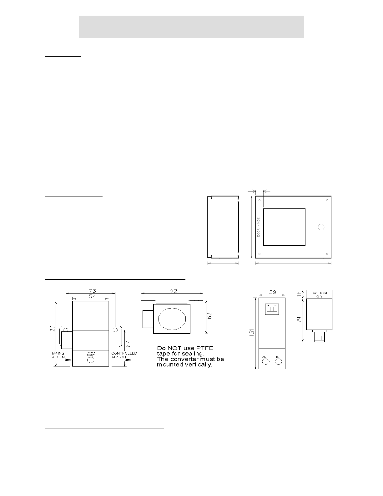
Cabinet Installation
2 in. (50mm)
The cabinet has rear mounting holes for M8 fixing.
When the Controller is supplied as a cabinet version the
mains supply is terminated inside the cabinet on a three
way terminal block. The incoming mains cable should be
securely fastened by the gland plate cord grip.
11.8 in
300mm
CUT OUT
8.27 in. x 7.01 in.
210 X 178
(210x178mm)
LOCK
Electro-Pneumatic ( E/P ) Converter Installation
IMI 101X converter
6 in.
(155mm)
Fairchild TA6000-406 converter
ENTRY GLAND PLATE
15 in.
(380mm)
CLEAN DRY OIL-FREE air of instrument quality, maximum supply pressure 100 PSI/7 Bar, filtered to 5
micron or better is required. The air line distance between the E/P Converter and the brake or clutch
should not exceed 5 metres or degradation of performance may occur.
High Current Driver ( HCD ) Installation
Use an HCD when the WebPro is used to drive a magnetic brake. Consult the manufacturer of the
magnetic brake for HCD recommendations. The HCD must be capable of delivering the rated brake
current and also be capable of supplying the rated brake voltage – usually 24 or 90 volts. Control of the
HCD output current must be controllable with a 0 to +10 volt signal.
AO-70173 6 Revision BA
WebPro Unwind Brake Tension Controller
Before connecting the HCD to the mains supply, ensure that the mains voltage matches the HCD
requirements. Connect the HCD control input common to the WebPro controller “0V analog” mTB4 and
the HCD control + signal input to the WebPro controls “control out 0/+10V” or TB4.
Caution: The HCD controller signal input connections must be isolated from the mains supply
connections or damage to the WebPro and the HCD will occur.
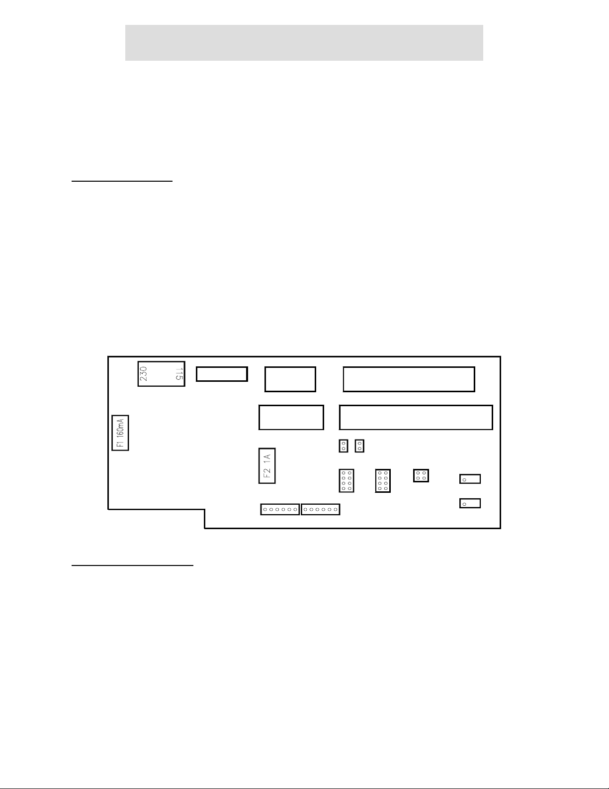
PCB Link Positions
The links LK1 to LK5 MUST be in the proper positions for correct operation.
It may be found more convenient to position the links before connecting the Controller.
LK1 Excitation Voltage Position B This gives 5.6V for Cleveland-Kidder transducers
LK1 Excitation Voltage Position A This gives 10V for ACDF and foil transducers
LK2 and LK3 IN For Cleveland-Kidder transducers to complete the bridge
LK2 and LK3 OUT For full bridge transducers, the bridges are complete
LK4 and LK5 Gain Position A Normal gain for Cleveland-Kidder transducers
LK4 and LK5 Gain Position B High gain for Cleveland-Kidder transducers
LK4 and LK5 Gain Position C Normal gain for ACDF and foil transducers
LK4 and LK5 Gain Position D High gain for ACDF and foil transducers
The high gain positions providing three times the normal gain are used if the transducers are oversized
and there is insufficient signal level for accurate calibration.
TB1
LEN 312 541
TB2
1
3245687 9 10 1411 12 13 15
132 456
TB3
LK2
LK3
LK4
A
B
C
D D
HD2 HD1
6 16 1
A
B
C
TB5
TB4
LK1LK5
AB
10965423 87131211
VR2 SPAN
VR1 ZERO
Controller Connections
WARNING - Disconnect the Controller completely before any electric welding is undertaken on the
machine. Failure to carry out this precaution could damage the Controller and will invalidate the warranty.
WARNING - The PCB uses devices sensitive to electrostatic voltages. Do NOT touch any components
without first using proper electrostatic discharge ESD precautions.
The Controller uses Wago Cage Clamp terminals, it is recommended that the correct tool is used when
inserting the cables. Wago part number 210-120 is available from Wago or CMC Inc.
Do NOT strain the terminals or the PCB. The terminals are suitable for cable sizes 12-24 AWG, 0.1-
2.5sqmm. The cable ends should be terminated with ferrules or crimp tags.
It is necessary to remove the rear cover to connect the Controller, set the links and select the mains
supply voltage. Remove the rear cover and fit the cable gland (supplied loose) to the rear cover. Feed the
mains cable through the cable gland and connect to the two part connect as shown. Feed the transducer
AO-70173 7 Revision BA
 Loading...