

Cleveland XVI 9-PCSM-L, XVI 9-PCGM-300-L, XVI 9-PCGM-250-L, XVI 9-PCEM-48-L, XVI 9-PCDM-L User Manual
Page 1
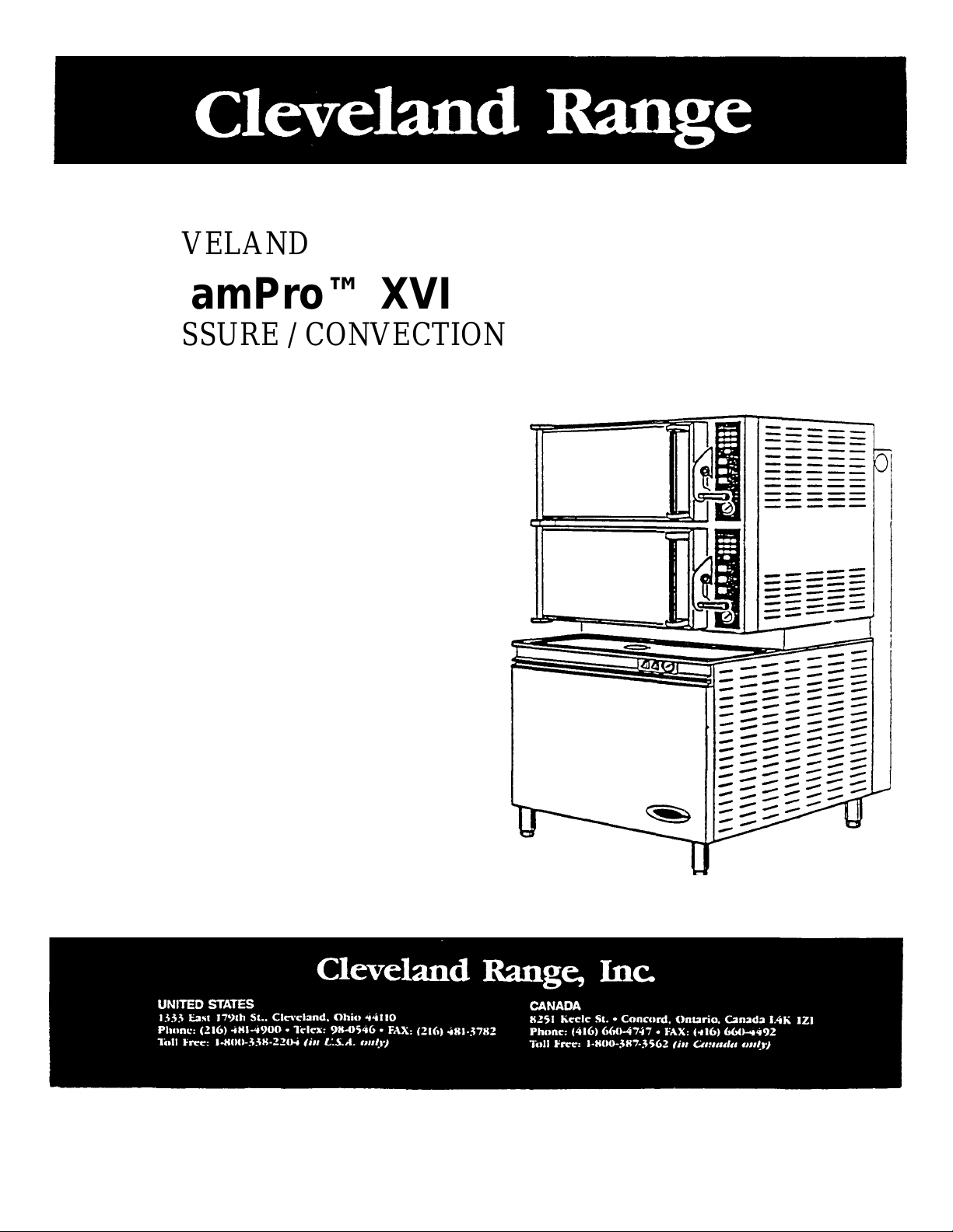
CLEVELAND
SteamPro™ XVI
PRESSURE / CONVECTION
STEAMER
OWNERS
MANUAL
Models: 9-PCEM -48-L
9-PCGM -250-L
9-PCGM -300-L
9-PCDM -L
9-PCSM -L
R
e
v
.
1
P
{
r
Printed 01/90
PCS-02
Page 2
Cleveland ALCO
PUBLICATION IMPROVEMENT RECOMMENDATION
Users of this publication are encouraged to report errors, omissions and
their recommendations for improving the publication. This sheet is
provided for that purpose. To file a Publication Improvement
Recommendation, fill in the information requested below, fold, tape and
mail this prepaid business reply form.
This Publication Improve ment
Recommendation pertains to manual __________________________ _____________
__________________________ Publication Date
of Manual
The following information Installation
was discovered during: (check one) Other (specify)__________________
Recommendation:_____________________________________________
(Be specific by referencing your remarks to page numbers, step numbers, etc.)
__________________________________________________________________________________________
__________________________________________________________________________________________
__________________________________________________________________________________________
__________________________________________________________________________________________
__________________________________________________________________________________________
__________________________________________________________________________________________
__________________________________________________________________________________________
__________________________________________________________________________________________
(Continue on back if needed)
Your name _____________________________________
(Please print)
Service office ___________________________________
(City) (State)
Telephone _____________________________________
(Area code) (Number)
Page 3
TABLE OF CONTENTS
Specification Information Page
9-PCEM-L (Electric) 3-4
9-PCGM-L (Gas) 5-6
9-PCDM-L (Direct Steam) 7-8
9-PCSM-L (Steam Coil) 9-10
Inspection and Unpacking 11
Installation Instructions 11
Installation Policies 11
Installation Ins tructions for all models 11-13
Installation Check 13
Introduction to SteamPro XVI Ownership 14
Operational Safety 14-15
Operational Functions 15-17
Control Panel Overview 16-17
Timer Information 16-17
Timer Programming 17
Timer Bypass
Operating Mode Selection
Basic Sequence of Operation 17-18
Start-Up and Preheat 18-19
Steaming Operation 19
Preventative Maintenance 20-21
Steamer Timer Programming Guide 22-23
Parts Breakdown 24-38
Electrical Wiring Diagram 39-40
Maintenance and Repair Center Information 41
Page 4
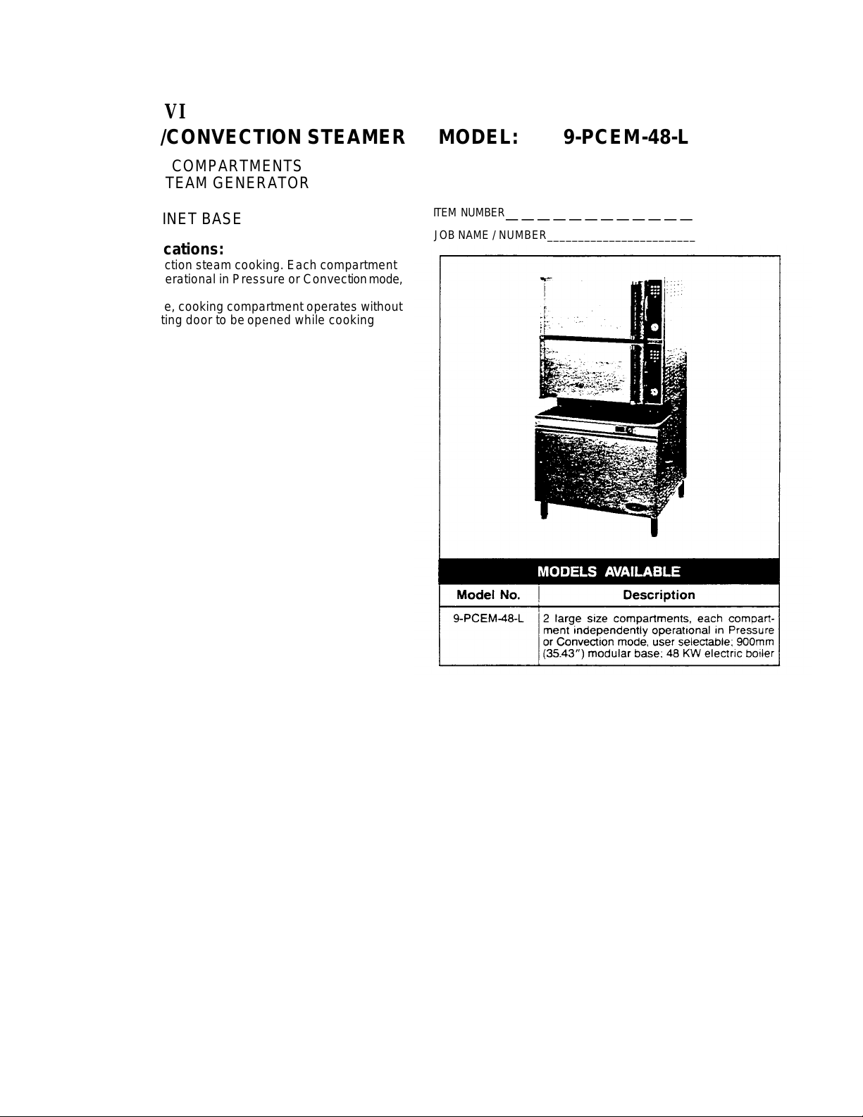
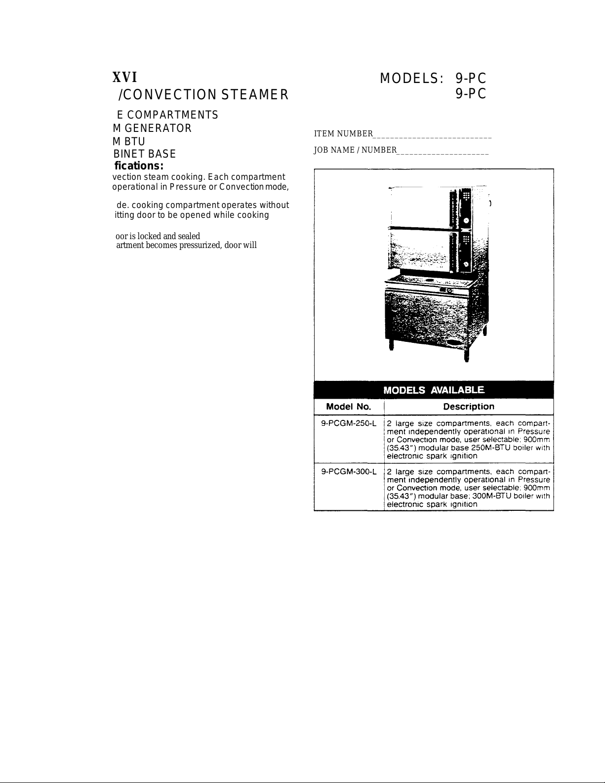
SteamPro® XVI
PRESSURE/CONVECTION STEAMER MODEL: 9-PCEM -48-L
• TWO LARGE COMPARTMENTS
• ELECTRIC STEAM GENERATOR
48 KW
• 900mm CABINET BASE
General Specifications:
• Pressure or Convection steam cooking. Each compartment
independently operational in Pressure or Convection mode,
user selectable
• In Convection mode, cooking compartment operates without
pressure, permitting door to be opened while cooking
continues
• In Pressure mode, door is locked and sealed
• At any time a compartment becomes pressurized, door will
automatically lock for safety
• Solid state, digital timer with wipe clean touch control panel:
one per compartment, each with 99 minute capacity plus
selectable "Repeat Cycle" feature
• High speed cooking with 10 psi operating pressure
• Standard voltage is 208V, 60 Hz, 3 phase, 3 wire
• Automatic temperature compensated timing action for
consistent product results
• Alternate manual operation mode (Convection only)
• "Clean Cove" corners in cooking compartments — easy to
clean
• Solid state controls for boiler and steam flow
• 15 psi safety valve
• Insulated cooking compartments
• Type 304 Stainless Steel: cooking compartments, doors,
table top
• Exterior sheathing is type 304 Stainless Steel, #4 finish
• Four Stainless Steel legs with level adjustment
• Serviceable from the front: solid state timers, electrical
controls and components, all boiler controls and components, compartment drain lines and steam injection tubes
• Capacity for either 12" x 20" pans or 18" x 26" bun pans
(none furnished standard)
• Single cold water connection
• Boiler empties under pressure (blows down) automatically
upon each shut -down, automatic water fill upon start-up —
single button control*
• Standard control panel languages are English, French and
Spanish
ITEM NUMBER
JOB NAME / NUMBER__________________________________
———————————————
Options and Accessories:
"California Code" boiler controls compliance kit factory
installed. Single button control replaced by two button
controls
Voltages other than standard a
Cooking pans
8", 10" or 12" adjustable legs
Stainless Steel base frame (FSS)
3.
Page 5
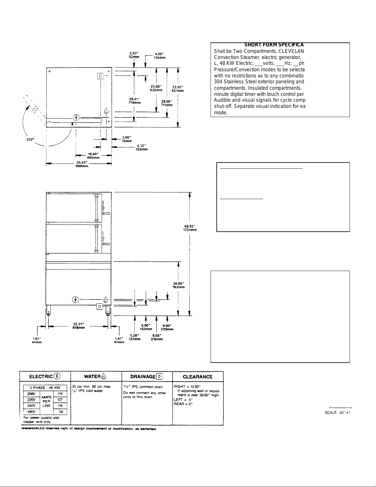
SHORT FORM SPECIFICATION
Shall be Two Compartments, CLEVELAND Pressure/
Convection Steamer, electric generator, Model 9-PCEM-48L, 48 KW Electric; ___volts, ___Hz, __phase, 3 wire.
Pressure/Convection modes to be selectable at user's option
with no restrictions as to any combination of modes. Type
304 Stainless Steel exterior paneling and cooking
compartments. Insulated compartments. One solid state, 99
minute digital timer with touch control per compartment.
Audible and visual signals for cycle completion and steam
shut-off. Separate visual indication for each operational
mode.
•Each compartment has capacity for:
Eight, 12" x 20" x 2 1/2" pans. Can accommodate
18" x 26" bun pans.
• Many local codes exist and it is the responsibility of the
owner and installer to comply with those codes.
•Cleveland/ALCO equipment is built to comply with
applicable standards for manufacturers. Included among
those approval agencies are: UL, A.G.A., NSF,
ASME/N.Bd., CSA, CGA, ETL, and others.
The recommended minimum water quality standards
whether untreated or pre-treated, based upon 10 hours of
use per day, and a Daily Slowdown, are as follows:
TOTAL DISSOLVED SOLIDS less than 60 parts per million
TOTAL ALKALINITY less than 20 parts per million
SILICA less than13 parts per million
pH FACTOR greater than 75
Consult a local water treatment specialist for an on site
water analysis for recommendations concerning steam
generator feed water treatment (if required), in order to
remove or reduce harmful concentrations of minerals. The
use of highly mineralized water will mean that more frequent
servicing of the steam generator will be necessary. The fact
that a water supply is potable is not proof that it will be
suitable for the generator.
WATER QUALITY REQUIREMENT
4.
Page 6
SteamPro® XVI
PRESSURE/CONVECTION STEAMER
• TWO LARGE COMPARTMENTS
• GAS STEAM GENERATOR
250 or 300M BTU
• 900mm CABINET BASE
General Specifications:
• Pressure or Convection steam cooking. Each compartment
independently operational in Pressure or Convection mode,
user selectable
• In Convection mode. cooking compartment operates without
pressure, permitting door to be opened while cooking
continues
• In Pressure mode, door is locked and sealed
• At any time a compartment becomes pressurized, door will
automatically lock for safety
• Solid state, digital timer with wipe clean touch control panel,
one per compartment, each wit h 99 minute capacity plus
selectable "Repeat Cycle" feature
• Automatic temperature compensated timing action for
consistent product results
• Alternate manual operation mode (Convection only)
• "Clean Cove" corners in cooking compartments — easy to clean
• Solid state controls for boiler and steam flow
• 15 psi safety valve
• Insulated cooking compartments
• Type 304 Stainless Steel: cooking compartments, doors, table top
• Exterior sheathing is type 304 Stainless Steel, #4 finish
• Four Stainless Steel legs with level adjustment
• Serviceable from the front: solid state timers, electrical
controls and components, all boiler controls and components, compartment drain lines and steam injection tubes
• Capacity for either 12" x 20" pans or 18" x 26" bun pans
• Single cold water connection
• Boiler empties under pressure (blows down) automatically
upon each shut -down, automatic water fill upon start-up —
single button control.'
• Standard control panel languages are English, French and
Spanish
• Electronic spark ignition
MODELS: 9-PCGM-250-L
9-PCGM-300-L
ITEM NUMBER___________________________
JOB NAME / NUMBER______________________
Options and Accessories:
* "California Code" boiler controls compliance kit factory
installed. Single button control replaced by two button
controls
Gas other than natural
Cooking pans
8", 10" or 12" adjustable legs
Stainless Steel base frame (FSS)
5.
Page 7
NATURAL
PROPANE
1” IPS for
Used above 2,000 ft. altitude.
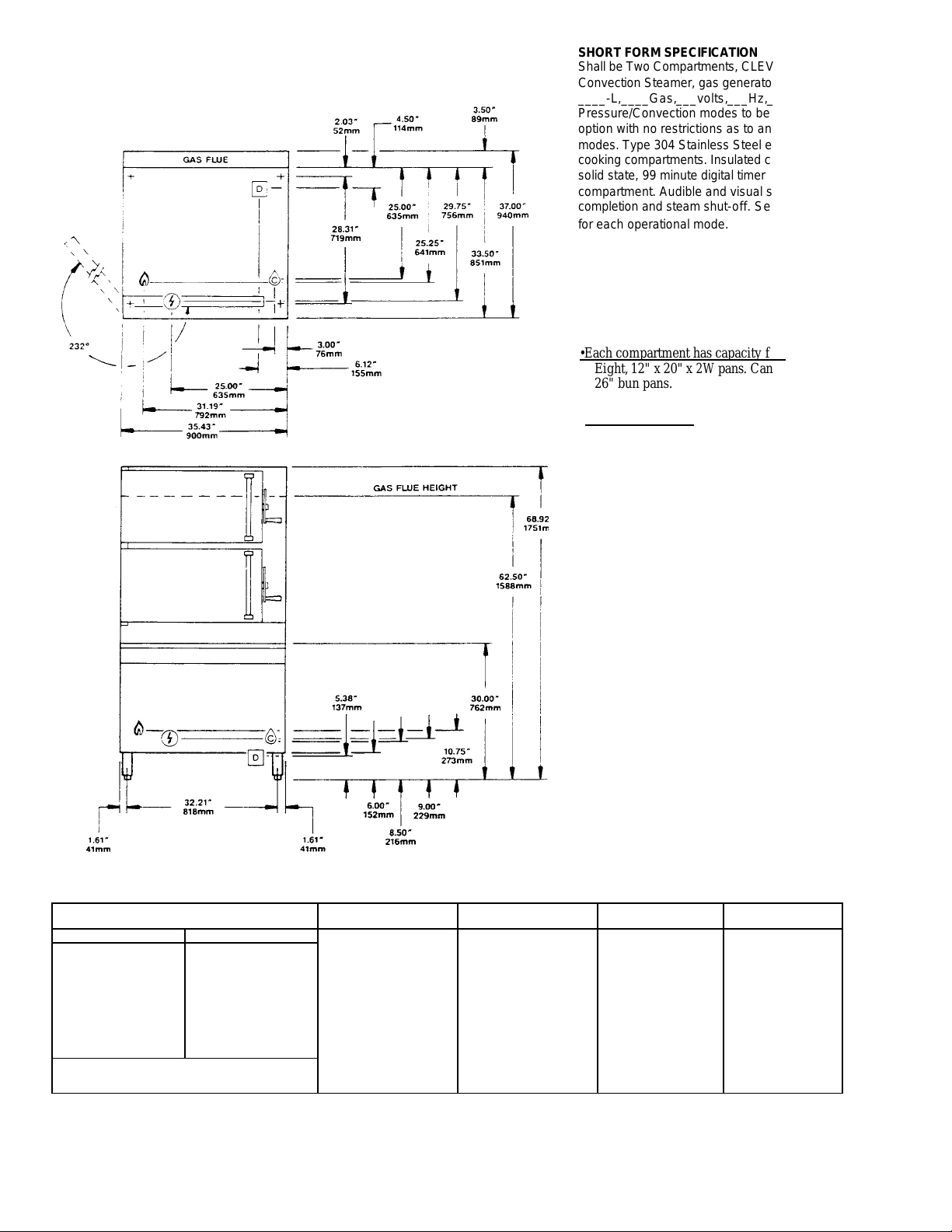
SHORT FORM SPECIFICATION
•Each compartment has capacity for:
Shall be Two Compartments, CLEVELAND Pressure/
Convection Steamer, gas generator, Model 9-PCGM ____-L,____Gas,___volts,___Hz,___phase.
Pressure/Convection modes to be selectable at user's
option with no restrictions as to any combination of
modes. Type 304 Stainless Steel exterior paneling and
cooking compartments. Insulated compartments. One
solid state, 99 minute digital timer with touch control per
compartment. Audible and visual signals for cycle
completion and steam shut-off. Separate visual indication
for each operational mode.
Eight, 12" x 20" x 2W pans. Can accommodate 18" x
26" bun pans.
•Many local codes exist and it is the responsibility of the
owner and installer to comply with those codes.
•Cleveland/ALCO equipment is built to comply with
applicable standards for manufacturers. Included among
those approval agencies are UL, A.G.A., NSF,
ASME/N.Bd., CSA, CGA, ETL, and others.
WATER QUALITY REQUIREMENT
The recommended minimum water quality standards
whether untreated or pre-treated, based upon 10
hours of use per day, and a Daily Blowdown, are as
follows:
TOTAL DISSOLVED SOLIDS less than 60 parts per million
TOTAL ALKALINITY less than 20 parts per million
SILICA less than 13 parts per million
pH FACTOR greater than 7.5
Consult a local water treatment specialist for an onsite
water analysis for recommendations concerning
steam generator feed water treatment (if required),
in order to remove or reduce harmful concentrations of
minerals. The use of highly mineralized water will mean
that more frequent servicing of the steam generator will be
necessary. The fact that a water supply is potable is not
proof that it will be suitable for the generator.
GAS ELECTRIC WATER DRAINAGE CLEARANCE
Piping-1” IPS for
240,000 BTU or more.
Supply pressure
4.00” W.C. Min.
14.00” W.C. Max.
Manufacturer must be notified if unit is to be
Cleveland/ALCO reserves right of design improvement or modification as warranted.
Piping-
Supply pressure
12.00” W.C. Min.
14.00” W.C. Max
240,000 BTU
or more.
115V-1 PH 25
watts per Compartment.
50 watts boiler control.
35 psi min. 60 psi max.
'/4” - IPS cold water
6.
1 1/2" IPS common
drain.
Do not connect any
other units to this
drain.
RIGHT = 12"
If adjoining wall or
equipment is over
30.00" high.
LEFT = 0"
REAR = 0"
For use only in
non-combustible
locations
Page 8
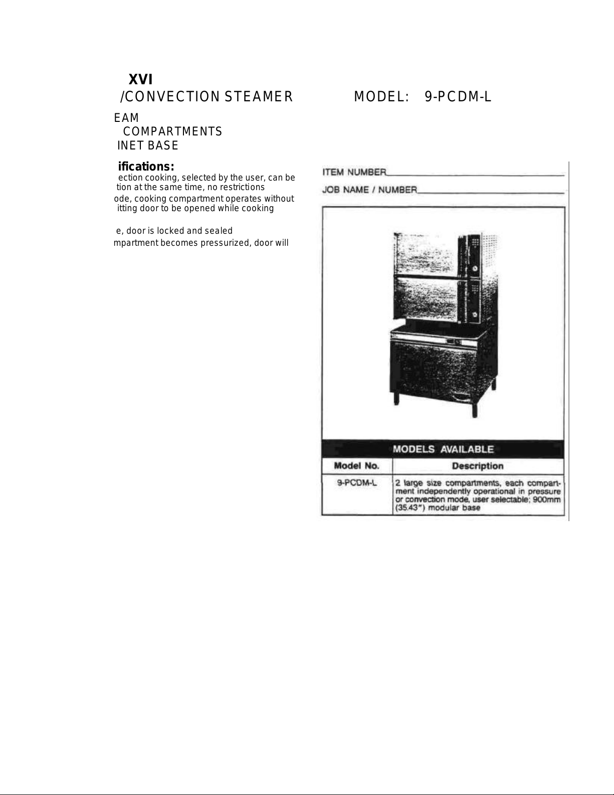
SteamPro™
XVI
PRESSURE/CONVECTION STEAMER
DIRECT STEAM
TWO LARGE COMPARTMENTS
900mm CABINET BASE
General Specifications:
• Pressure or Convection cooking, selected by the user, can be
in any combination at the same time, no restrictions
• In Convection mode, cooking compartment operates without
pressure, permitting door to be opened while cooking
continues
• In Pressure mode, door is locked and sealed
• At any time a compartment becomes pressurized, door will
automatically lock for sa fety
• Solid state, digital timer with wipe clean touch control panel,
one per compartment, each with 99 minute capacity plus
selectable "Repeat Cycle" feature
• High speed cooking with 10 psi operating pressure
• Automatic temperature compensated timing action for
consistent product results
• Alternate manual operation mode (Convection only)
• "Clean Cove" corners in cooking compartments — easy to
clean
• 15 psi safety valve
• Insulated cooking compartments
• Type 304 Stainless Steel: cooking compartments, doors, table
top
• Exterior sheathing is Type 304 Stainless Steel, #4 finish
• Four Stainless Steel legs with level adjustment
• Serviceable from the front: solid state timers, electrical
controls and components, compartment drain lines and
steam injection tubes
• Capacity for either 12" x 20" pans or 18" x 26" bun pans
(none furnished standard)
• Single cold water connection
• Standard control panel languages are English, French, and
Spanish
A Clean, non-toxic, uncontaminated steam is required at the
steamed
MODEL: 9-PCDM-L
Options and Accessories:
Reversed door opening: hinges at right, controls on
left
Cooking pans
8", 10" or 12" adjustable legs
Stainless steel base frame (FSS)
7.
Page 9
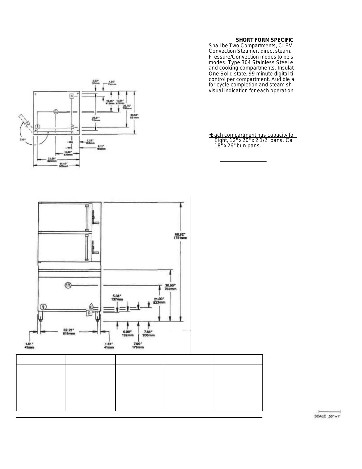
Shall be Two Compartments, CLEVELAND, Pressure/
SHORT FORM SPECIFICATION
Convection Steamer, direct steam, Model 9-PCDM-L,
Pressure/Convection modes to be selectable at user's
modes. Type 304 Stainless Steel exterior paneling
and cooking compartments. Insulated compartments.
One Solid state, 99 minute digital timer with touch
control per compartment. Audible and visual signals
for cycle completion and steam shut -off. Separate
visual indication for each operational mode.
•Each compartment has capacity for:
Eight, 12" x 20" x 2 1/2" pans. Can accommodate
18" x 26" bun pans.
•Many local codes exist and it is the responsibility of
the owner and installer to comply with those codes.
•Cleveland/ALCO equipment is built to comply with
applicable standards for ma nufacturers. Included
among those approval agencies are: UL, A.G.A.,
NSF, ASME/N.Bd., CSA, CGA, ETL, and others.
DIRECT STEAM WATER (C) DRAINAGE (D) ELECTRIC® CLEARANCE
Steam Supply:
Furnish 3/4" IPS mm.
line. 40 psi mm. SO psi
max. required, for
pressures above 50 psi.
an additional pressure
reducing valve must be
specified.
Cleveland/ALCO reserves right of design improvement Of modification — warranted
40 psi min. 60 psi max.
3/8 IPS cold water
1 1/2" IPS common
drain.
Do not connect any
other units to this drain.
115V-1PH 25 watts per
compartment
RIGHT - 12.00"
If adjoining wall or equipment is over 30.00" high.
LEFT = 0"
REAR = 0"
8.
Page 10
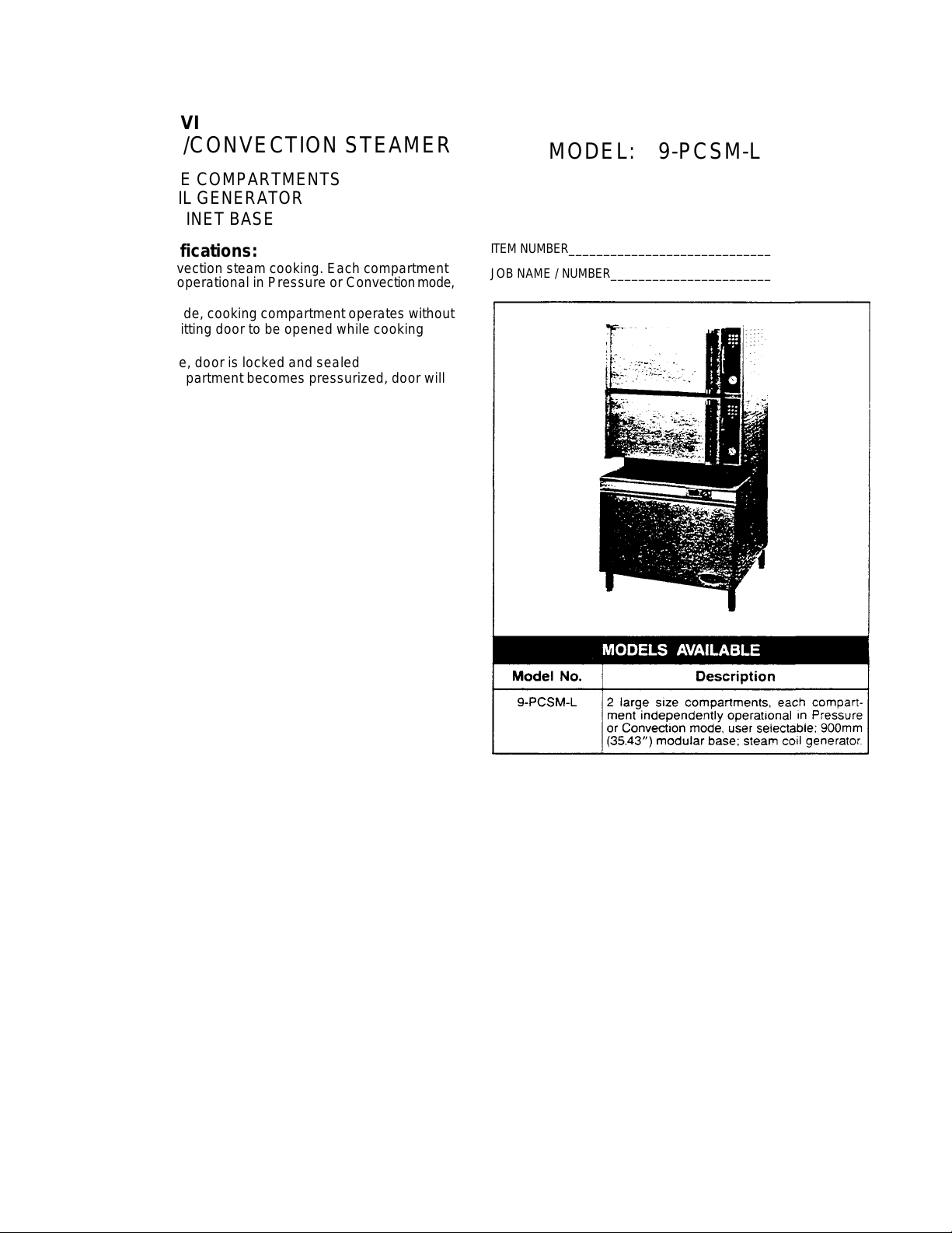
SteamPro® XVI
PRESSURE/CONVECTION STEAMER
• TWO LARGE COMPARTMENTS
• STEAM COIL GENERATOR
• 900mm CABINET BASE
General Specifications:
• Pressure or Convection steam cooking. Each compartment
independently operational in Pressure or Convection mode,
user selectable
• In Convection mode, cooking compartment operates without
pressure, permitting door to be opened while cooking
continues
• In Pressure mode, door is locked and sealed
• At any time a compartment becomes pressurized, door will
automatically lock for safety
• 10 psi operating pressure in Pressure mode
• Solid state, digital timer with wipe clean touch control panel,
one per compartment, each with 99 minute capacity plus
selectable "Repeat Cycle" feature
• Automatic temperat ure compensated timing action for
consistent product results
• "Clean Cove" corners in cooking compartments — easy to
clean
• Solid state controls for boiler and steam flow
• 15 psi safety valve
• Insulated cooking compartments
• Type 304 Stainless Steel: cooking compartments, doors, table top
• Exterior sheathing is type 304 Stainless Steel, #4 finish
• Four Stainless Steel legs with level adjustment
• Serviceable from the front: solid state timers, electrical
controls and components, all boiler controls and components, compartment drain lines and steam injection tubes
• Capacity for either 12" x 20" pans or 18" x 26" bun pans
• Single cold water connection
• Boiler empties under pressure (blows down) automatically
upon each shut -down, automatic water fill upon start-up
• Standard control panel languages are English, French, and
Spanish
MODEL: 9-PCSM-L
ITEM NUMBER________________________________________
JOB NAME / NUMBER__________________________________
Options and Accessories:
"California Code" boiler controls compliance kit factory
installed.
Voltages other than standard (115V)
Cooking pans
Stainless steel base frame (FSS)
8", 10" or 12" adjustable legs
9.
Page 11
ing
Cleveland/ALCO reserves right of design improvement or modification, as warranted.
SHORT FORM SPECIFICATION
Scale .
50
"=1’
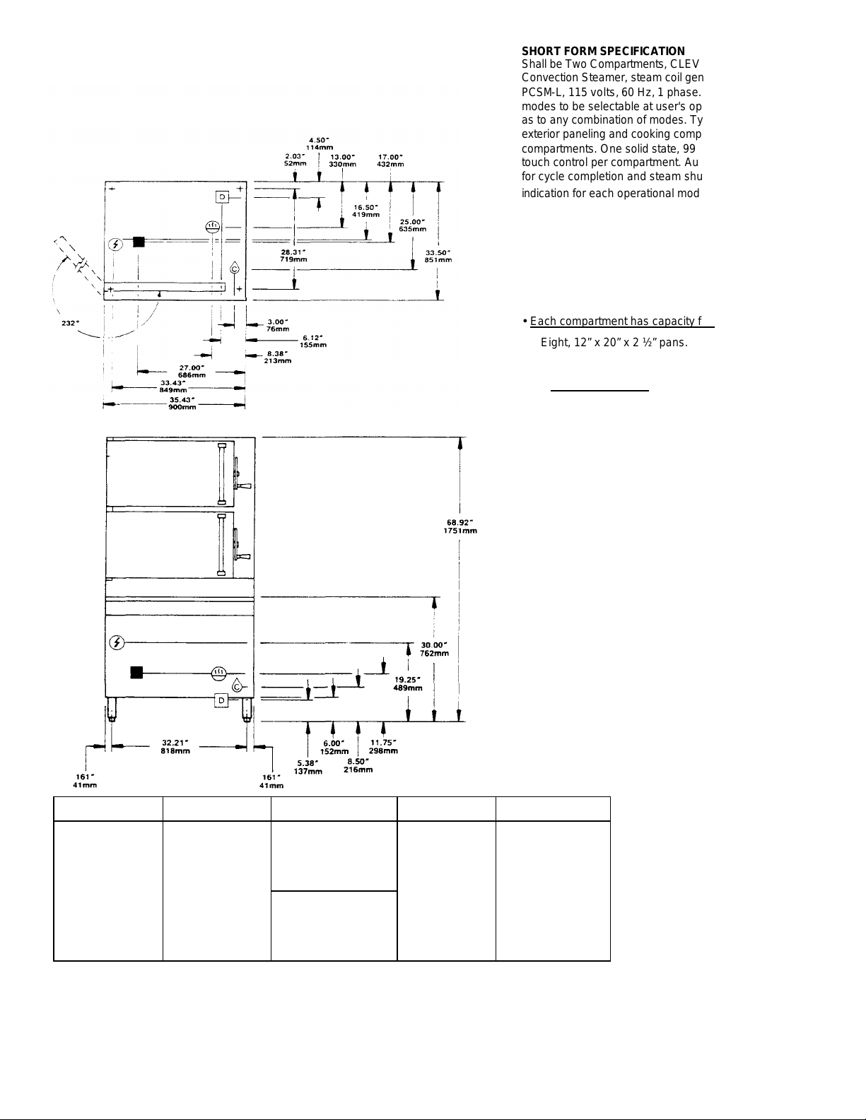
Shall be Two Compartments, CLEVELAND Pressure/
Convection Steamer, steam coil generator, Model 9PCSM -L, 115 volts, 60 Hz, 1 phase. Pressure/Convection
modes to be selectable at user's option with no restrictions
as to any combination of modes. Type 304 Stainless Steel
exterior paneling and cooking compartments. Insulated
compartments. One solid state, 99 minute digital timer with
touch control per compartment. Audible and visual signals
for cycle completion and steam shut-off. Separate visual
indication for each operational mode.
• Each compartment has capacity for:
Eight, 12” x 20” x 2 ½” pans.
• Many local codes exist and it is the responsibility of
the owner and installer to comply with those codes.
• Cleveland/ALCO equipment is built to comply with
applicable standards for manufactures. Included
among those approval agencies are: UL, A.G.A.,
NSF, ASME/N.Bd., CSA, ETL, and others.
WATER QUALITY REQUIREMENT
The recommended minimum water quality standards whether
untreated or pre-treated, based upon 10 hours of use per day,
and a Daily Slowdown, are as follows:
TOTAL DISSOLVED SOLIDS less than 60 parts per million
TOTAL ALKALINITY less than 20 parts per million
SILICA less than 13 parts per million
pH FACTOR greater than 7.5
Consult a local water treatment specialist for an onsite
water analysis for recommendations concerning steam
generator feed water treatment (if required), in order to
remove or reduce harmful concentrations of minerals. The use
of highly mineralized water will mean that more
frequent servicing of the steam generator will be necessary.
the fact that a water supply is potable is not proof that it will be
suitable for the generator.
STEAM COIL WATER DRAINAGE ELECTRIC CLEARANCE
Steam Supply
Piping: • ¾” IPS
min. for 35 to 50 psi.
• For pressure
above 50 psi, a
pressure reduc
valve must be
specified.
35 psi. min. 60 psi ©
max. 3/8" IPS cold
water.
1 ½” IPS common
drain.
Do not connect any
other units to this drain.
Steam Cold Drain
•3/4” IPS. Do not
connect to common
drain.
115V-1 PH
25 watts per
compartment.
RIGHT - 12.00"
If adjoining wall or
equipment is over
30.00" high.
LEFT = 0”
REAR =0”
10.
Page 12
INSPECTION
Before unpacking, visually inspect the shipping carton for evidence of any damage during shipment. It there are signs of
possible damage, do not unpack the equipment Notify the carrier that delivered the shipment so the carton and its contents can
be examined for any damage claims. Fill out all appropriate forms and have the examining carrier sign and date each form. Do
not install damaged equipment.
UNPACKING
1. If the shipping carton has no signs of possible damage, unpack the equipment. To remove the unit from the carton. it is
easiest to slit the carton in 4 corners and "peel" it away from the steamer. After removing the carton, examine the steamer
for signs of possible damage If damage exists, detail your observations on a claims form and give to the shipper (keep a
copy for your records).
2. If the equipment is undamaged, lif t the unit to the counter top or stand where it is to be installed. Damaged equipment
should not be installed.
INSTALLATION INSTRUCTIONS
Warning: Installation of this unit must be done by qualified plumbing and electrical installation personnel working to all
applicable local and national codes. Improper installation of this product could cause injury or damage and void customer
warranty.
INSTALLATION POLICIES:
• Cleveland/ALCO equipment is designed and manufactured to comply with applicable standards for manufacturers. Included
among those certification agencies which have approved the safety of the equipment design and construction are:
UL NSF, CSA, and others.
• Cleveland/ALCO equipment is designed and certified for safe operation only when permanently installed in accordance with
local and/or national codes. Many local codes exist, and it is the responsibility of the owner and installer to comply with these
codes.
• In no event shall Cleveland/ALCO assume any liability for damage or injury resulting from installations which are not in strict
compliance with our Installation Instructions. Specifically, Cleveland/ALCO will not assume any liability for damage or injury
resulting from improper installation of equipment, including, but not limited to, temporary or mobile installations.
INSTALLATION INSTRUCTIONS FOR ALL MODELS:
WARNING INSTALLER: ALL SteamPro XVI units MUST BE securely anchored to the floor at all times.
1. These instructions must be retained by the owner/user for future reference. Gas-fired boilers are only to be
installed in noncombustible areas that have provisions for adequate air supply. The term "boiler" will be used
synonymously with "steam generator".
2. Position: For proper operation and drainage, the equipment must be level. It should be placed next to an open floor
drain. DO NOT POSITION THE UNIT DIRECTLY ABOVE THE FLOOR DRAIN. Observe all clearance
requirements to provide air supply for proper operation, as well as sufficient clearance for servicing. The
surrounding area must be free and dear or combustibles. Dimensions and clearance specifications for each model
are shown on the specification sheets enclosed.
3. Inst all in accordance with local codes and/or the National Electrical Code ANS1/NFPA No. 70-1984. Installation in
Canada must be in accordance with the Canadian Electrical Code CSA Standard C22-1. Equipment that Is
connected to electricity must be grounded by the installer A wiring diagram Is provided inside the base cabinet.
4. Attach drain extension piping to the drain connection to carry steam condensate and boiler drain water away from
the cabinet, to the floor drain. The drain extension piping must be 1 1/ 2" diameter minimum (ips), and not exceed
6 feet in length, with no more than two elbows, before draining. The drain extension termination MUST vent freely
to the air (not plumbed solidly into the floor drain). Each unit requires its own 1 1/2" diameter drain extension. Do
not interconnect any other drains to this units drain extension. Ensure that the boiler's manual drain valve is
closed.
11.
Page 13
5. Connect COLD water supply plumbing to the line strainer. (Never connect hot water to the boiler's water fill line
strainer). Constant flow pressure must be maintained between 40 and 60 psi. and not experience a pressure drop
below 35 psi when other appliances are used. If the water pressure exceeds 60 psi, a pressure reducing valve must
be installed in the water supply plumbing to reduce the water pressure to less than 60 psi. Locations and pressure
data are shown on the specification sheet. 3/8" ips plumbing is required for water supply lines regardless of length.
Rush water supply lines thoroughly before connecting them to the unit Use water which Is low in total dissolved
solids content and low in gas content to prevent Internal scaling, pitting and corrosion of the steam generator and
carry-over of minerals into the steam. (Water which is fit to drink can still contain highly detrimental impurities.)
6. Turn on the cold water supply to the unit. Ensure that the manual water valve, inside the base cabinet, is open.
7. Connect the primary fuel supply in accordance with the following instructions. Location and other data are shown on
the specification sheet.
For Gas-Fired Steam Generators:
Post, in a prominent location. Instructions to be followed In the event the user smells gas. This information shall be
obtained by consulting the local gas supplier. Install as a sediment trap (drip leg) in the gas supply line, then connect
gas supply piping to the boiler's gas valve piping. GAS-FIRED EQUIPMENT IS DESIGNED FOR INSTALLATION
ONLY IN NON-COMBUSTIBLE LOCATIONS. Location, plumbing size, and pressure data Is shown on the specification
sheet. Boilers rated at less than 225.000 BTU require 3/4" ips gas supply piping, and boilers rated at 225,000 BTU
or more require 1" gas supply piping. Natural gas supply pressure must be between 4"-14" water column and LP gas
supply pressure must be between 12" -14" water column. NEVER EXCEED 14" WATER COLUMN (1/2 psi) GAS
PRESSURE. If the gas supply pressure ex ceeds 14" water column a pressure regulating valve must be installed in
the gas supply plumbing to reduce the gas pressure to less than 14" water column. Installation must be In accordance with
local codes or in the absence of local codes, with the National Fuel Gas Code, ANSlZ223.1-1984. Installation in
Canada must be in accordance with Installation Codes for Gas Burning Appliances and equipment B149.1 and
Bl49.2-Use a gas pipe Joint compound which is resistant to LP gas. Turn the gas valve's control knob to "on" (the
word "on" on the knob will be opposite the Index on the valve's body). Test all pipe joints for leaks with soap and
water solution. New obstruct the flow or combustion and ventilation air. Observe clearance requirements to provide
adequate air openings into the combustion chamber. The appliance and its individual shut off valve must be
disconnected from the gas supply piping system during any pressure testing of that system at test pressures in
excess of 1/2 pri (14" water column or 3.45 kPa). The appliance must be isolated from the gas supply piping system
at test pressures equal to or less than 1/2 psi (14" water column or 3.45 kPa). A permanent 115 volt electrical
connection is required at the Junction box. Location shown on the specification sheet. The unit must be electrically
grounded by the installer.
For Electric Powered Steam Generator's
Connect electric power location and data are shown on the specification sheet Provide connection as required
by your unit; either directly to the single contactor, or to the terminal block (when equipped with mutiple contactors).
Electric supply must match power requirements specified on the data plate inside the base cabinet. The copper
wiring must be adequate to carry the required current at the rated voltage. A separate fused disconnect switch must
be supplied and Installed. The unit must be electrically grounded by the installer.
For Direct-Steam-Connected Steamers:
Connect steam supply piping to the input side or the line strainer. Location and pressure data are shown on the
specification sheet Flush the steam line thoroughly before connecting it to the steamer ensure an adequate volume
or steam, the branch steam supply line must be 3/4" ips minimum. A permanent 115 volt electrical connection is
required at the junction box. The junction box location is shown on the specification sheet. The unit must be
electrically grounded by the installer.
8. Press the "power" on-off rocker switch. The red indicator light in the switch will come on and the boiler will begin to fill
with water. Direct-Steam-Connected steamers are not equipped with self -generating, boilers or "steam" switches.
Therefore, these models do not require the 5 minute boiler water fill time, nor is it necessary to push a "steam"
switch to produce steam, as Indicated In step #9. As soon as the pressure gauge on the control panel registers 10
psi (5 psi for pressure steamers), preheating may begin. (If you are operating a direct steam-connected steamer,
steps #9 and #10 do not apply. Refer directly to step #11.)
9. After about five minutes the amber light in the "steam" switch will glow indicating the water has reached a safe
operating level in the boiler. The "steam" switch can now be pressed (momentarily) in order to produce steam in the
boiler. This will activate the energy source (electric heaters, gas burners, or steam solenoid valve), and
12.
Page 14

Connect (To “House
Steam Supply
With or Without Kettles
to be connected to the “house” steam supply.
the amber light will go out The energy source cannot be activated until the boiler contains sufficient water indicated
by the amber light. The "steam" switch must be pushed to re-start the steamer after it is shut off for any reason
(including a momentary power interruption). Do not attempt to start or operate this appliance during a power failure.
Whenever the amber light is illuminated, the heater, steam supply, or burners are off, and no steam is being
generated.
NOTE FOR UNITS CONTAINING GAS-FIRED BOILERS ONLY: If the burners fail to ignite in four seconds,. a
safety circuit will de-energize the system. In this event, momentarily press the power switch to the "off"
position, then back to the "on" position. (The "steam" switch amber light should be on. Wait 5 minutes, then
press the "steam" switch to start the burner ignition cycle once again.)
10. Check to ensure that the water in the boiler's sight gauge glass stays at about 2/3 full when the boiler is started up
and operated.
11. Check to ensure that the steam pressure gauge registers 10 psi. The steam pressure is factory adjusted to provide
the proper pressure in some cases, however the factory setting may shift due to shaking in transit, and resetting
will be required after installation. Proper adjustments and maintenance procedures should be made only by
qualified service personnel. The factory pressure settings shown in the accompanying chart should never be
exceeded.
12. When the installation is complete and free of leaks, refer to the OPERATIONAL FUNCTIONS section, in order to
understand proper operation of the unit.
GUAGE PRESSURE READING WITH NO STEAM FLOW (STATIC PRESSURE)
Self-Contained Steam Generator Gas or Electric Self-Contained Steam Coil Generator Direct-
Steamer’s
Pressure
Equipment
Steam Generator Only 5 psi N/A 5 psi 10 psi 5 psi 10 psi 30-45 psi N/A N/A
Pressure Steamer N/A 5 psi 10 psi 5 psi 10 psi 30-45 psi 5 psi 12-45 psi
Pressure Steamer
With Any Kettle
Steam Generator Only
10 psi
Kettle Only N/A 10 psi 15 psi N/A N/A N/A N/A 5-45 psi
Convection Steamer
Reducing
Valve
5 psi 10 psi 15 psi 5 psi 10 psi 30-45 psi 5 psi 12-45 psi
N/A 10 psi 15 psi 10 psi 15 psi 30-45 psi N/A N/A
N/A 10 psi 15 psi 10 psi 15 psi 35-45 psi 10 psi 15-45 psi
Operating
Pressure
Switch
High Limit
Safety
Pressure
Switch
Operating
Pressure
Switch
High Limit
Safety
Pressure
Switch
Kettles are
Steam
Supply
Pressure
Range
Steam Supply)
Steamer’s
Pressure
Reducing
Valve
Pressure
Range
INSTALLATION CHECK
Proper operation of the Cleveland SteamPTO XVl Steamer is dependant upon proper installation. After the steamer has
been installed, a few quick checks could save unnecessary service calls.
1. The SteamPro'" XVI Steamer requires a cold water connection for proper, efficient operation. DO NOT USE HOT
WATER. The cold water must be connected to the line strainer located at the front lower-right of the steamer base.
Ensure that the manual water su pply valve is open.
The cold water feed One must maintain 40 to 60 psi constant flow pressure, and not experience a pressure drop
when other appliances are used. Both the hot and cold water lines should maintain 35 to 60 psi flow pressure.
2. The unit must be level.
3. On electric units, the supply voltage must agree with the voltage Indicated on the rating plate inside the base cabinet,
and with the voltage shown on the packing slip. The unit must be protected with a separate fused disconnect and be
properly grounded, in accordance with the National Electric Code.
Page 15

4. On Gas Steam Coil and Direct-Steam-Connected units. there is a 115 volt connection required at the junction box
located in the base ax the bottom front.
5. The drain extension termination must vent freely to the air (not plumbed solidly into the floor drain). The drain extension
piping must have a gravity flow, be 1 1/2" diameter minimum (IPS), and not exceed 6 feet in length with no more than
two elbows before draining. Each steamer requires its own 1 1/2" diameter drain extension. Do not interconnect any
other drains to this steamers' drain extension. Ensure that the manual drain valve is dosed.
REMEMBER: D0 NOT POSITION THE UNIT DIRECTLY ABOVE THE FLOOR DRAIN. AS RISING CLOUDS OF STEAM
CONDENSATE DAMAGE ELECTRONC COMPONENTS.
CAUTION Failure to comp ly with these drain instructions could result in the accumulation of hot water in the
cooking compartment .
6. On Direct-Connect units the incoming steam pressure must be 35 to 50 psi. and anything less than 35 psi will not
effectively operate this unit.
7. Gas-fired steam generators should never exceed a 14" water column or 1/2 psi gas pressure. Gas equipment is
designed for installation only in non-combustible locations.
Installer: Please complete and mail the Installer's Checklist.
INTRODUCTION TO SteamPr o XVI OWNERSHIP
To get the full advantage of steam cooking, Cleveland/ALCO SteamPro XVI must be properly installed. A steamer which
is improperly installed, improperly used, improperly maintained or improperly repaired will create a dangerous condition
and may cause injury to personnel.
OPERATIONAL SAFETY:
Your Cleveland/ALCO SteamPro XVI will require minimum servicing provided it is operated according to instructions and
given the care recommended.
Make sure that responsible personnel understand how your steam cooking equipment should be operated and cared for.
Proper use and maintenance pay handsome dividends in long life and satisfactory performance.
Safe steam cooking equipment operation dictates that every owner of steam cooking equipment should follow these rules
for operational safety:
1) Begin a comprehensive continuous program of intend and external steam cooking equipment inspection.
2) Never allow untrained personnel to operate or experiment with a steamer.
3) At the end of each days operation -
• Remove any spoiled food, then wash the racks and compartment interiors thoroughly with mild detergent in warm
water.
• Rinse thoroughly with clean warm water.
WARNING — Let rinse water drain through compartment drain opening. If water does not drain freely, drain lines must
be cleaned out before cooking again. Clogged or slow drains are dangerous because hot water may collect and spill out
when compartment doors are opened after a cooking cycle.
• When cleaning the steamer's exterior, BE SURE THAT POWER TO THE UNIT IS OFF. Never apply water to
controls on the console. Use a damp cloth for cleaning.
4) Always leave the compartment door ajar when the compartment is not in use.
14.
Page 16

• On boiler equipped steamers, blow down the boiler. Then refill the boiler with water, and shut off the power
switch.
• On direct connected steamers, cut off the main steam supply with a valve ahead of the steamer's pressure
reducing valve
6) Read and follow the Cleveland/ALCO Instructions on steamer and steam generator maintenance in the Owners
Manual,
7) Only allow the use of replacement parts which are factory authorized as equivalent to the parts being replaced, to
preserve the certification of Underwriters Laboratories, American Gas Association, Canadian Standards Association or Canadian Gas Association (as applicable).
8) Never allow unqualified personnel to tamper with the steamer or steam generator controls, or to replace worn out
parts.
FOR YOUR SAFETY
Do not store or use gasoline or other flammable vapors
and liquids in the vicinity of this or any other appliance
9) For gas fired steam generators (boilers): Post In a prominent location Instructions to be followed in the event
the user smells gas. This Information shall be obtained by consulting the local gas supplier.
For additional information on steamer safety, refer to the steamer operating procedure on page
Instructions for the occasional servicing that will be needed are given on pages 18-19 Servicing beyond these in-
structions should not be attempted without specialized skills and experience. Such attempts may void the warranty on
the equipment.
OPERATIONAL FUNCTIONS
Operation of the Cleveland SteamPro XVI Is very easy. Each operator should become familiar the following operation
functions and procedures to effectively start, operate and shut down the steamer.
CONTROL PANEL OVERVIEW: ————————————————————————————————————
CAUTION The touch pad controls are designed to be pressed with finger tips only. Be careful not to use fingernails,
kitchen utensils or anything that could cause damage.
"DIGITAL TIME DISPLAY" - Time programmed In the Pressure or Convection mode will be displayed here In red
numbers. A maximum of "99" minutes can be programmed. During operation, time displayed will countdown to "00".
"00" will blink until the compartment door is opened. (When using the Manual mode, time displayed will stay at "00".
The Timer is not used in this mode.)
"TIMER TOUCH PANEL” - "Number" touch pads are used to program the desired cooking time for Pressure or
Convection mode. The Time entered will be shown in the DIGITAL TIME DISPLAY
"START/CANCEL" - Press this touch pad once to START the compartment operational mode process. The green
indicator light (LED 1) will come on and stay on until the touch pad is pressed again to CANCEL. When the
compartment temperature reaches 194%F (in either Pressure or Convection mode) the green indicator light (LED 2)
will come on and start flashing until countdown is completed. START/CANCEL is not used when in "Manual
Operation" mode or TIMER BYPASS function.
"PRESSURE OPERATION" -Press this touch pad to change from the Convection mode to the Pressure mode. The
red indicator light (LED 3) will come on and stay on until the steaming cycle is completed, the compartment is depressurized (the "LOCKED" symbol will go out) and the compartment door is unlatched.
WARNING: At the end of a Pressure mode steaming cycle, wait at least 2 minutes for the compartment to depressurize and drain before opening the compartment door. Premature opening can result in steam or hot water
bums.
15.
Page 17

"MANUAL OPERATION" - Press the touch pad to operate the compartment in the Convection mode but without the
use of the START/CANCEL touch pad, the TIMER TOUCH PANEL or the DIGITAL TIME DISPLAY. The green
indicator light (LED 4) will come on and stay on until the touch pad is pressed again. "COMPARTMENT PRESSURE" Use this gauge to monitor the compartment pressure.
WARNING Open the compartment door only when the Pressure Gauge returns to "0" PSI. If the gauge does not indicate “0” PSI,
do not attempt to pull up on the compartment latch handle or to open the compartment door. The Unit must be serviced by qualified
personnel.
TIMER INFORMATION
Each cooking compartment is equipped with an independent electronic digital timer, which has maximum programming capability of
99 minutes. Each timer is connected to a temperature sensing device the cooking compartment. This sensor will allow the timer to
count down only when the internal compartment{s} reaches proper cooking temperature. This assures uniformity In the final
product as the timer automatically compensates for the amount and temperature of the in the compartment.
16.
Page 18

TIMER SETTINGS (programming)
Press the "Start/Cancel" touch pad once to ensure that no time remains in the timer. Program the desired cooking time. by
pressing the appropriate number pads. The time programmed will be displayed above the "Number" touch pads. Ex ample,
pressing the "1" pad, then the "2" pad programs 12 minutes.
Press the "Start/Cancel" pad to start the timer. This starts the flow of steam into the cooking compartment - Remember the timer
will begin to count down only after the compartment reaches proper cooking temperatures. After the programmed time has
counted down to zero, an alarm will sound for 5 seconds and steam flow (into the cooking compartment) will stop in "Manual
Operation" mode, the steamer operates as a Convection steamer only.
The timer must be programmed and started before steam will begin to flow into the selected steaming compartment,
whether in Pressure or Convection mode.
In either Pressure or Convection mode, the desired cooking time must be programmed Into the timer and the
"Start/Cancel" touch pad must be pressed (to begin the flow of steam). The timer will delay its' countdown, automatically
compensating for defrosting and/or food product heat -up time. Example: If you have programmed the timer at 10
minutes. It may in fact take 11 or 12 minutes for the programmed time to expire and the signal to sound. This is normal.
The additional time was used to heat the compartment and to remove the air. When the timer counts down to zero, the
Digital Timer Display will flash, a signal will sound and the steam flow to the cooking compartment will shut-off. To stop
the Digital Timer Display from flashing, press "Start/Cancel" touch pad once. (The signal will also sound when the
compartment is heated to announce the beginning of the timer count down.)
COMPARTMENT DOOR LATCH/LOCK INFORMATION
Latching:
The door handle/latch are positive and offer some resistance to movement. This is normal. Also note that
latching the door is a two (2) step movement. Be sure to latch completely into the second step, otherwise the
unit will not operate.
Unlatching:
In the Convection mode, the door is never "Locked" and can be unlatched and opened at anytime. If the door Is
opened during the cooking cycle for food seasoning or inspection, keep your hands out of the steaming
compartment to prevent burning them. Use hot pads when removing pans from compartment Steam will still
flow into the compartment when the handle is in the down, latched position, regardless of whether the door Is
closed or open. Steam flow stops when the handle is unlatched.
To open the compartment door, partially unlatch the door. If some water comes out of the compartment, or off
the door, allow it to finish dripping before completely unlatching and opening the door.
Locking/Unlocking:
In the Pressure mode, the "Locked" symbol will be illuminated, indicating that the door latch is locked and cannot be
opened. Only when the "Locked" symbol is no longer illustrated and the steaming compartment de-pressurized can
the door be unlatched and opened.
BASIC SEQUENCE OF OPERATION
CONVECTION STEAMING MODE ———————————————————————————————
1. User programs desired steaming time (0 to 99 minutes) via numeric keypad-
2. Compartment door is dosed and latched.
3. Cycle is started by pressing "Start/Cancel"" touch pad.
4. Steam is introduced into compartment via steam distribution tubes.
5. Steaming begins.
6. Compartment temperature rises to 194°F.
17.
Page 19

7. Countdown timing begins. Audio signal sounds for 1 second. Countdown indicator (LED2) begins flashing.
8. "Timer" counts down to zero. Alarm sounds for 4 seconds.
9. User presses "Start/Cancel" touch pad. Digital Time Display stops flashing.
10. End of Cycle.
PRESSURE STEAMING MODE ————————————————————————————————————
1. User programs desired steaming time (0 to 99 minutes) via numeric keypad. Pressure mode is selected by
pressing "Pressure Operation" touch pad. Mode indicator (LED2) lights.
2. Compartment door is closed, latched and automatically locked.
3. Steaming cycle is initiated by pressing "Start/Cancel" touch pad. Indicator (LED1) rights.
4. Steam is introduced into compartment via steam distribution tubes.
5. Steaming begins.
6. Compartment temperature rises to 194 F.
7. Countdown timing begins. Audio signal sounds for 1 second. Countdown indicator (LED2) begins flashing.
8. Pressure begins to build in compartment
9. Steaming continues at 10 psi pressure. Timer counts to zero.
10. Digital Timer Display begins to flash. Touch pad panel indicators (LED's 1.2 and 3) turn off.
11. Steam flow stops.
12. Compartment releases pressure.
13. Compartment door is automatically unlocked.
14. User presses "Start/Cancel" touch pad to cancel mode.
15. End of Cycle.
START-UP AND PREHEAT
CAUTION Do not attempt to start or operate this appliance during a power failure.
1. Check the cooking compartments to ensure that the steam tubes and drain screens are in place and secure. On
steamers equipped wit h self-contained boilers, check inside the steamers' base cabinet to ensure that the manual
drain valve is dosed and the manual water supply valve is open.
18.
Page 20

2. Press the red "power on-off" rocker switch located near the steam pressure gauge, at the right side of the base
cabinet console. The red indicator light in the switch will come on and the boiler will begin to fill with water.
Direct-steam -connected steamers are not equipped with self-generating boilers or "steam" switches. Therefore,
these models do not require the 5 minute boiler water fill time, nor is it necessary to push a "steam switch" to
produce steam, as indicated in step #3 below. As soon as the pressure gauge on the control panel register,
10 psi, preheating may begin. (If you are operating a direct-steam -connected steamer, "skip* step #3, and refer
directly to step #4.)
3. After three to five minutes, the amber light in the "STEAM" switch will glow. Indicating the water has reached a safe
operating level in the boiler. The "STEAM" switch can now be pressed (momentarily) in order to produce steam in
the boiler. This will activate the energy source electric heaters, gas burners, or steam solenoid valve), and the
amber light will go out. The energy source cannot be activated until the boiler contains sufficient water, indicated by
the amber light The "STEAM" switch must be pressed to re-start the steamer after it is shut off for any reason
(including a momentary power Interruption). No attempt should be made to operate the equipment during a power
failure. Whenever the amber right is illuminated, the heaters, steam supply, or burners are OFF and no steam Is
being generated.
NOTE FOR STEAMERS CONTAINING GAS-FIRED BOILERS ONLY: If the burners fail to ignite in four seconds,
a safety circuit will de-energize the system. In this event, momentarily press the power switch to the "off" position,
then back to the "on" position. The "STEAM" switch amber light should be on. Wait 5 minutes, then press the
"STEAM" switch to start the burner Ignition cycle once again. In about 20 minutes she steam pressure gauge on
the control panel should register 10 psi.
4. You can now preheat the cooking compartment(s). Cooking compartments should always be preheated before
cooking.
5. To preheat, dose and latch the compartment door securely. Set the Digital Timer Display for one minute. It
will be several minutes before the time display counts down. When the preheating is completed, the steam will
automatically shut off and a five second signal will sound.
6. Your steamer is now ready to begin a Steaming Operation.
19.
Page 21

PREVENTATIVE MAINTENANCE
BOILER SHUTDOWN: (Applies only to steamers which have a self -contained boiler).
The red-lighted power switch must be shut off for 3 minutes every 8 hours to automatically drain highly mineralized
water from the boiler (which reduces the formation of scale). See step 1 below.
DAILY CLEAN-UP:
Your Cleveland SteamPro XVI Steamer, must be cleaned regularly to maintain its fast, efficient cooking per-formance,
and to ensure its continued safe, reliable operation.
1. The boiler must be drained (blowdown) daily. or after maximum of 8 hours of use. If the boiler's feed water contains
more than 300 parts per million to total dissolved solids, the boiler must have a blowdown two or three times daily.
"Blowdown" means draining the boiler while under pressure.
The boiler "BLOWDOWN" is performed by simply shutting off the steamers' red-lighted "POWER" switch while the
boiler's at normal 10 psi operating pressure. When the bottom of the "POWER" rocker switch is pushed, its' red light
goes out, and the drain valve automatically opens, draining the boiler. An automatically timed drain water condenser
will flush the drain for 3 minutes, then shut off. The steamer is then again ready for use.
When steam is produced, the water in the boiler to being distilled. During this process, the minerals that come into the
boiler with the water remain in the boiler as the water boils away as steam- When allowed to accumulate, the water
becomes nightly mineralized, which results In erratic operation, lime build-up corrosion, and premature failures. In some
cases complete boiler replacement becomes necessary, which is extremely expensive. By draining the boiler under
pressure, most sediment present will be flushed down the drain.
2. The steamer is equipped with a drain screen in the back of each cooking compartment. No compartment should be
operated without its' drain screen in place. This screen prevents large food parades from entering and possibly
plugging the drain line. Any restriction of the drain line will cause an accumulation of hot water in the cooking
compartment, which could cause injury when the door is opened. It also may adversely affect the convection action
of the steam in the compartment, which is critical to optimum performance. Pouring USDA approv ed drain cleaner
through the compartment drains once a week will help to ensure an open drain. A manual (hand crank) drain auger,
or "snake", may be safely used to clear obstructions in the compartment drains. Do not use a power auger, as
damage to the plastic drain system may result.
CAUTION With steamer off, open the cooking compartment door (s)) and allow the steamer to cool before cleaning
the cooking compartments) and their components.
3. At the end or each day's operation, wash the pan slide racks, drain screens, door gaskets, and compartment interiors
with mild detergent and warm water, either by hand or in a dishwasher. Rinse water should drain free ty through the
compartment drain openings. If it does not, the drain must be cleaned before using the steamer.
4. Always leave compartment door opened a little when not in use to prolong gasket life.
WEEKLY CLEAN-UP:
1. Once a week, remove the steam tubes and dean the orifices. First remove the pan slide racks by lifting upward and
toward the center of the compartment. Pressing backward on the steam tube will allow its front eyelet to dear the
compartment stud. The tube is then angled toward the center or the compartment just enough to dear the stud and
be pulled forward, out or its socket. The orifices can be cleaned easily with a paper clip. Then, thoroughly wash and
rinse all steam tubes. This can be done in a dishwasher. Lubricate each tube's open end with cooking oil before
replacing in the steamer's compartment. Be sure ail the steam tubes are securely in place before activating the
compartment. The tubes are interchangeable and may be placed in any spot In either compartment.
EXTERIOR CLEAN-UP:
WARNING Always turn off power to equipment before using water to wash equipment.
1. Allow steamer to cool before washing. Use the same cleaners and cleaning procedures as for other kitchen surfaces
of stainless steel or aluminum. Mild soapy water, with a dear water rinses, is recommended. Do not allow water to
run into electrical controls.
20.
Page 22

EXTENDED MAINTENANCE:
A qualified serviceman should be contacted for routine Preventative Maintenance.
1. Periodic boiler inspections should be made by a qualified serviceman.
2. Once every three months the cold water line strainer should be cleaned,
3. The "blowdown" procedure will not completely remove the mineral deposits that adhere to the top of the boiler. A
chemical descaling should be done by a boiler treatment specialist. This should be done once a year in average
water conditions, but in poor-water areas it may be needed two or three times a year.
Cleveland/ALCO supports a worldwide network of Maintenance and Repair Centers, which are regional distributors of
pans and service. Contact your nearest Maintenance and Repair Center for the name of an authorized service agency
In your area, or for replacement parts, or information regarding the proper maintenance and repair of your equipment In
order to preserve the various agency safety certifications (UL, A.G.A., CGA, NSF, ASME/NU. Bd., etc.), only factory supplied replacement parts should be used. The use of other than factory -supplied replacement parts will void the
warranty.
21 .
Page 23

CLEVELAND RANGE COMPANY
MINUTES
Beans, gr
een
2"
cut 6 5 French cut
4 5"
whole
6 4
Broccoli, spears
3 2-3
flowerettes
2-3 1-2
chopped
6-8 Brussels sprouts
4-5 4
Cabbage.
12-16 wedges/head
4 Cabbage.
whole
- to remove leaves
2
(or cabbage rolls
Carrots, baby whole
10 6
sliced, crinkle cut
7-8 3
diced 2
Cauliflower, flowerettes
4-5 3-4
whole
10 Celery, diagonal cut
1
1/2" 3
diced 2 1 minced
1 Corn. yellow whole kernel
2 on cob, cobbettes
6 12—
Mixed vegetables
3-4 Mushro
oms. whole
(1 1/2"
dia.) 3
sliced 1
Onions, diced, sliced
2-3 1
whole
4 2
Peas, green
2 Potatoes, whole
8
oz. 30-35
peeled. Quartered, fresh
12-19 peeled, diced
8-10 Potatoes, sweet whole
30-35 Spinach leaf
2 21— chopped
21—
Squa
sh, acorn halves
15 butternut, quartered
7 whipped*
20—
spaghetti squash, halves
15-18 Tomatoes, whole, sliced*
1 Turnips, whole
20-25 Zucchini. sliced
2-4 2-4
SEAFOODS:
Steam all seafoods on a perforated pan with catch pan.
Cod fillets,
5
oz. portions
3 4
Crab legs. king
4-6 Snow crab
2-4 Crab. live.
4
oz- 4 3/4 - 1 Ib. 12
Halibut.
6-8
oz. portions
4-6 6-8
Lobster, whole.
1 Ib. 7-9
Lobster tails,
8
oz. 8-10
defrosted, butterflied
4-6 Mussels in shell
2 Oysters in shell
2-4 Red snapper,
8
oz. 4-5 4-5
Salmon steak.
8
oz. 6 /
Shrimp.
10
ct per Ib. IQF
3 4-6 5 Ib. block, peeled
&
deveined
30
ct 6-
8**
potato salad
10-12
Soft cooked
3
Coddled
6 Poached in a cup
2-3
Blanch for peeling
Fresh: Avocado
1 Apple, cored
1 Grapefruit
1 Orange
1 Apricot
1 Pineapple, whole
2 Dried*: add water to re
-
hydrate
Apple
10 Apricot
10
Peach
10
Pear 10
Prune
10
THE CLEVELAND CONVECTION STEAMER™
TIMER SETTINGS
Timer settings are approximate due to the differences in food quality, age, shape and the degree of "doneness" desired. It is not necessary to add water.
Perforated pans are recommended. Starred items (*) must be cooked in solid pans or containers. Items marked with two stars (**) require handling in two steps.
First, steam for approximately 1/2 the time shown, remove from steamer. separate thawed portion, or stir, and return to the steamer for the time remaining. The
compensating feature of the timer allows the cooking compartment to reach cooking temperature before the preset time starts to count up.
VEGETABLES: Fresh Frozen
Artichoke 12
Asparagus, spears 4 6
Clams in shell 3-5
MINUTES
Fresh Frozen
Eggplant sliced, diced 1
22.
5 to. block. green. 26-30 ct (nested pan) 10**
EGGS: Medium Sized
Hard cooked (or egg salad.
Scrambled* 6-7 **
FRUITS: MINUTES
Page 24

CLEVELAND RANGE COMPANY
for gravy, sauces, beef stock
and soups. The size of portion.
thickness of cut grade, should be considered when selecting
POULTRY: Fresh Frozen
Chicken.
5-8
oz. breaded
pieces
18
-20 rnin. halves. 1 1/4
-
1 1/2 lb. per
Pork,
Chop,
4
count/lb.
10
Italian sausage.
4
oz. portion
10
Ribs. 3 lb. and down
20
-
26
Cubes. 1 1/2"
6
-
7 min./lb.
6
min./lb.
Ground
chuck for chill
4 min./lb.
4
-6 min./lb.
Pot roast, choice
8
-12 min./lb.
Rump roast, choice
boned, rolled, tied
12 min./lb.
Meat loaf.
4
lb. loaf 5
min./lb.
Liver baby beet.
8 oz. Slice
2-4 2
-
4 Corned beef. 6
-
8 lb. cut
Using a
1/4" to
1"
steak, the steaming tim
e
listed below pro
-
duces a "rare" steak. A "well done" steak is first ste
amed to the
"rare" stage, then broiled or grilled for
1 %
minute on each
side. This "well done" steak shrinks less. is more tender and
chopped
8
oz.
4
Rib eye.
8
oz.
4
Top butt steak
6
oz.
4
8
oz.
6
Filet Mignon. butterflied
—
4oz.
3
8oz.
3
-
4 8
oz.
4
10
oz.
5
16
oz. whole (Chateaubriand)
8
12
oz. 7 T-bone— 12
oz. 5 16
oz. 8 18
oz. 8
Cabbage rolls, stuffed*
25
20
cover with tomato
sauce & serve
Casserole
dishes*
beet Stew,
20-25 25-30 stroganoff
20
-
25 25-30 Lasagna*. freshly prepared
20
-
25 25-30
Potatoes*: 2 1/2 random sliced
4
cups cold water/lb.
17
Beans*, pre
-
soaked overnight
1
lb. beans
* 1%
qts. water
45
Beans*.unsoaked.
1
Ib. be
ans.
* 1
1/2 qts. water
2 1/2 hrs
Steam in nested pans. Place pasta on used as a
La
sagna noodles
10-12" Macaroni, shells, elbow
10-12
** Rigatoni
10** Spaghetti, vermicelli
8** Spaghetti, regular
10**
THE CLEVELAND CONVECTION STEAMER™ TIMER
MEATS & POULTRY:
Steam meats and poultry in nested pans. as juices can be used
a timer setting for doneness.
MINUTES
Turkey, whole 6-8 min./lb. 6-8 min./lb.
half 20-24 min. 20-24 min.
PORK. SAUSAGE. HOT DOGS:
Hot dogs. 8 count/lb. 2
BEEF:
SETTINGS
(Continued)
MINUTES
Strip steak — 10 oz. 5
22 oz. 10
MINUTES
PREPARED ENTREES: Fresh Frozen
Full size pans
reheat each serving 4" 6-8
DEHYDRATED FOODS;
plus 5 cups cold water/lb. 12
RICE* BEANS
Rice*, long grain
12
add 1/2 water to pan 20-23 min./lb.
STEAKS
juicy: and. when served, is the same size as the "rare" steak.
MINUTES
Sirloins patties.
Refried beans*. 2 #10 cans 15-17
PASTA:
liner in a solid 2 1/2" pan. Cover |
Egg noodle*. 1/2" wide 4-6 **
2 1/2" perforated pan
pasta with cold water.
MINUTES
23.
Page 25

Electrical Box Assembly For Two
Probe Gas Generator
1. 20478 Timer, Solid State Interval - 3 Minute
2. 20528 Transformer - Spark Ignition Supply
3. 23198 Control Water Level
4. 03524 Relay, 120 V, 50/60 HZ, AL, DPDT
5. 03525 Socket, Relay
6. 44163 Box -Electric Assembly - For Gas Two Probe
24.
Page 26

Power Supply
100766 - Power Supply Board
25.
Page 27

Timer Panel Assembly
Panel Assembly, Instrument
Timer Assembly, Complete
Nut, 6-32, Plastic
Gauge, Pressure-30" Vac., 30 psi
26.
Page 28

1. 44169
Cable Ignition Asm.
2. 03546 Control Module, Direct Spark Ignition, 4 Second
3. 02361 Box, Handi-Box Electrical, 4 1/8" x 1 13/16" #180-1/2
4. 66037 Cover, Elect, Box Generator, 2 Probe
5. 44164 Terminal Block Assembly - 4 Pole Gas Units
6. 44163 Box - Electric Assembly - For Gas 2-Probe
Electrical Box Assembly For
Two Probe Gas Generator
Page 29

Latch Assembly
1. 450821 Plate, Weldment - Latch Mount PCL/PCS HL
2. 44148 Pawl Assembly - PCS/PCL – HL
3. 100771 Solenoid, 120 Vac., 60 HZ, Continuous Duty, Class F Insul.
4. 100768 Cylinder, Pressure Lock
5. 19972 Switch, Thermal Close 193+5 Deg. F, Open 173+5 Deg. F,
6. 100710 Sprint, Cam Arm Return
7. 46020 Handle Assembly
8. 101524 Cam/Arm Assembly - PCL/PCS - HL
9. 45084 Latch Assembly, Door-PCL/PCS - HL
28
Page 30

1. 20005 Switch, Rocker - Red
29.
Page 31

1. 19972 Switch, Thermal Close 193+5 Deg. F, Open 173+5 Deg. F, PCI
30.
Page 32

1. 101233 Water Regulator Assembly. (Wilkins)
2. 100218 Regulator, Water Pressure - 3/4" x 3/4" (PCL)
31.
Page 33

32.
Water Valve Assembly
1. 07169 Gauge 0-100 PSI, 2-1/2", 1/4" Bottom Mount, Brass Movement
2. 03606 Coupling, Full, Brass, 1/2"
3. 100976 Manifold, Water Valve Support PCL/PCS
4. 22241 Valve, Solenoid 2-Way NC 1/4 NPT, Orifice 5/32 1200/60
5. 22236 Valve, Solenoid, 3-Way, 120 V/60 HZ
6. 14304 Nipple, Yellow Brass, 1/4" x Close
7. 101061 Manifold, Water Assembly. PCL/PCS
Page 34

Plumbing Assembly
1. 565191 Fitting - Hose Drain Manifold
2. 15462 Orifice, Flow Regulator 1/8" GPM
3. 20211 Tee-Black 1"
4. 22238 Valve, Pinch 1"NPT
5. 100223 Tee 1"x 1/2" x 1" Black
6. 14553 Nozzle, Spray Drain Manifold GP1 - 1/8 GG Full Jet, Brass
Page 35

Steam Outlet Assembly
1. 101035 Valve, Safety, 3/4", 12 PSI
2. 101207 Trap, Thermostatic w/POL Seat
3. 100307 Piping, Steam Outlet -PCL, Rev. B End Gen., Gas 34.
Page 36

Steam Valve Assembly
1. 22193
Value, Solenoid
3/4 x 3/4,
2NC 120V, 60HZ
2. 05295 Elbow, Union 1/2" x 1/2", Female to Female Brass
3. 101794 Steam Value Assembly (PCL)
Page 37

Water Feed Assembly
1. 03276 Value Ball 1/4" Brass, Full Port
2. 22102 Value, Swing Check, 1/4" Brass, 36" Leads
3. 22223 Value, Solenoid, 1/4" NPT, Conduit 130-120 V
4. 100303 Clamp, Mounting - 3/8 Tee Elbow, Tube Fitting
5. 100339 Angle, Top Front -1200 MM Oyster Kettle Base
6. 100304 Piping, Water Feed Assembly 3/8", Rev. Bend Gen.
36.
Page 38

Heater Assembly
08165 Heater 12KW, 208-220V, 3" Square Flange, 3 Phase
08166 Heater, 12KW, 230-240V, 3" Square Flange, 3 Phase
8167 Heater, 12KW, 440-480V, 3" Square Flange, 3 Phase
07128 Heater Gasket
37.
Page 39

Drain Manifold Assembly
1. 1008983 Drain Manifold Assembly
2. 13252 Manifold-1.500" Dia., 8 1/2" Length-Black
Page 40

39.
Page 41

40.
 Loading...