

Cleveland SteamCraft Ultra 5 21-CET-16 User Manual

Statement of Responsibilities
This document is for use by experienced and trained Qualified Cleveland Range, LLC Authorized Service
Representatives who are familiar with both the safety procedures, and equipment they service.
Cleveland Range, LLC assumes no liability for any death, injury, equipment damage, or property damage
resulting from use of, improper use of, or failure to use the information contained in this document.
Cleveland Range, LLC has made every effort to provide accurate information in this document, but
cannot guarantee that this document does not contain unintentional errors and omissions.
The information in this document may be subject to technical and technological changes, revisions, or
updates.
Cleveland Range, LLC assumes no liability or responsibility regarding errata, changes, revisions, or
updates.
Qualified Cleveland Range, LLC Authorized Service Representatives are obligated to follow industry
standard safety procedures, including, but not limited to, OSHA regulations, and disconnect / lock out /
tag out procedures for all utilities including steam, and disconnect / lock out / tag out procedures for gas,
electric, and steam powered equipment and / or appliances
All utilities (gas, electric, water and steam) should be turned OFF to the equipment and locked out of
operation according to OSHA approved practices during any servicing of Cleveland Ran ge equipment
Qualified Cleveland Range, LLC Authorized Service Representatives are obligated to maintain up-to-date
knowledge, skills, materials and equipment.
Cleveland Range, LLC
1333 East 179th St., Cleveland, Ohio, U.S.A. 44110
Ph: 1-216-481-4900 Fx: 1-216-481-3782 Visit our Web Site at www.clevelandrange.com

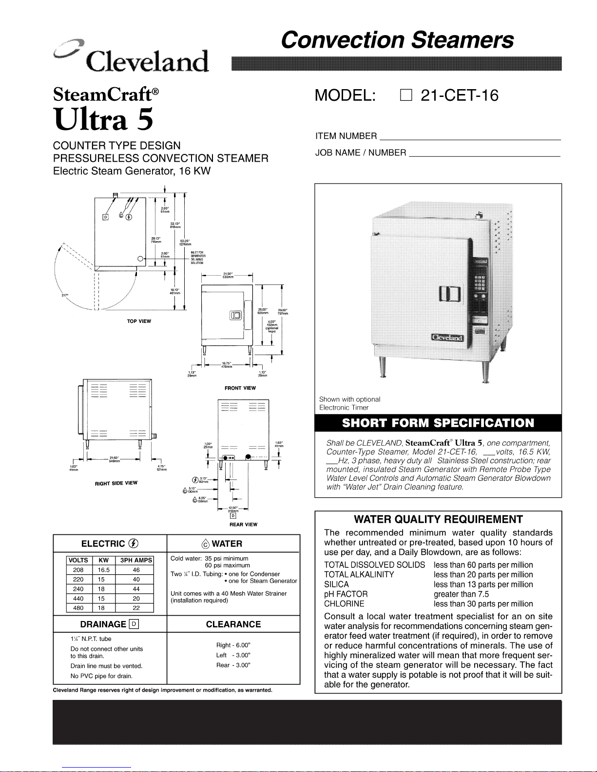
CLEVELAND RANGE 21CET16
SEQUENCE OF OPERATIONS
Mechanical Timer
1. Supply power is sent to the primary of the main transformer.
• 115 VAC is sent from the secondary of the main transformer to the on/off rocker,
1. To turn the unit on, depress the red on/off rocker switch.
• 115 VAC is sent to the red indicator light.
• 115 VAC is sent to the normally open drain valve closing it.
• 115 VAC is sent to H and N of the water level board
2. With the water level board energized and no water in the generator
• After a 5 second delay, 115 VAC is sent from the FILL terminal to the fill solenoid.
• The fill solenoid opens and the generator fills through the drain valve.
• The water fills to the low probe shorting it to ground
• 115 VAC is sent from the HEAT terminal to the timed manual switch.
• 115 VAC is sent to the preheat thermostat.
• 115 VAC is then sent through the high limits to the coil of condensate solenoid.
• The condensate solenoid opens sending cold water down the compartment
drain.
• 115 VAC is also sent through the high limits to the coil of the contactor.
• When the contactor is energized supply voltage is sent to both of the elements.
• The heat circuit will stay energized until the preheat thermostat opens at 185
degrees.
3. When the timed/manual switch is in the timed position and time is on the timer
• 115 VAC is sent from the timer to the coil of the R2 relay
• The R2 relay energizes
• R2B contacts close and 115 VAC is sent to the motor of the timer
• R2A contacts close and 115 VAC is through the optional door switch to the normally
closed contacts of the high limits
• 115 VAC is then sent through the high limit to the coil of condensate solenoid and the
coil of the mercury contactor.
• 115 VAC is sent to the clean light timer.
• When the clean light timer times down 115 VAC is sent to the clean light switch.
• When the clean light switch is depressed the clean light timer is reset.
4. When the contactor is energized supply voltage is sent to both of the elements.
5. When the timer times out 115 VAC is sent to the 3 second timer and then to the buzzer for 3
seconds.
6. When the water level reaches the high probe then 115 VAC is removed form the FILL
terminal and the fill solenoid is turned off.

7. After the water level drops below the high probe for 5 seconds 115 VAC is sent to the FILL
terminal again.
8. The red on/off rocker switch is depressed and the unit is turned off.
• 115 VAC is removed from the timer and heat circuits.
• 115 VAC is removed from the normally open drain valve allowing the steamer to drain.
• 115 VAC is sent to the 3-minute timer and the fill solenoid is energized for 3 minutes
flushing the drain.
FILL VALVE
L106380 G
THERMAL SWITCH
2
BLOWDOWN OPTION
( HEAT STANDBY )
POWER SWITCH
DRAIN VALVE
HI LIMIT
SWITCHES
1
3
CONDENSER
VALVE
CONTACTOR
3 MIN TIMER
2 1
POWER ON
R
N
PROBES
HIXL C
WATER
BOARD
FILL
H
HEAT
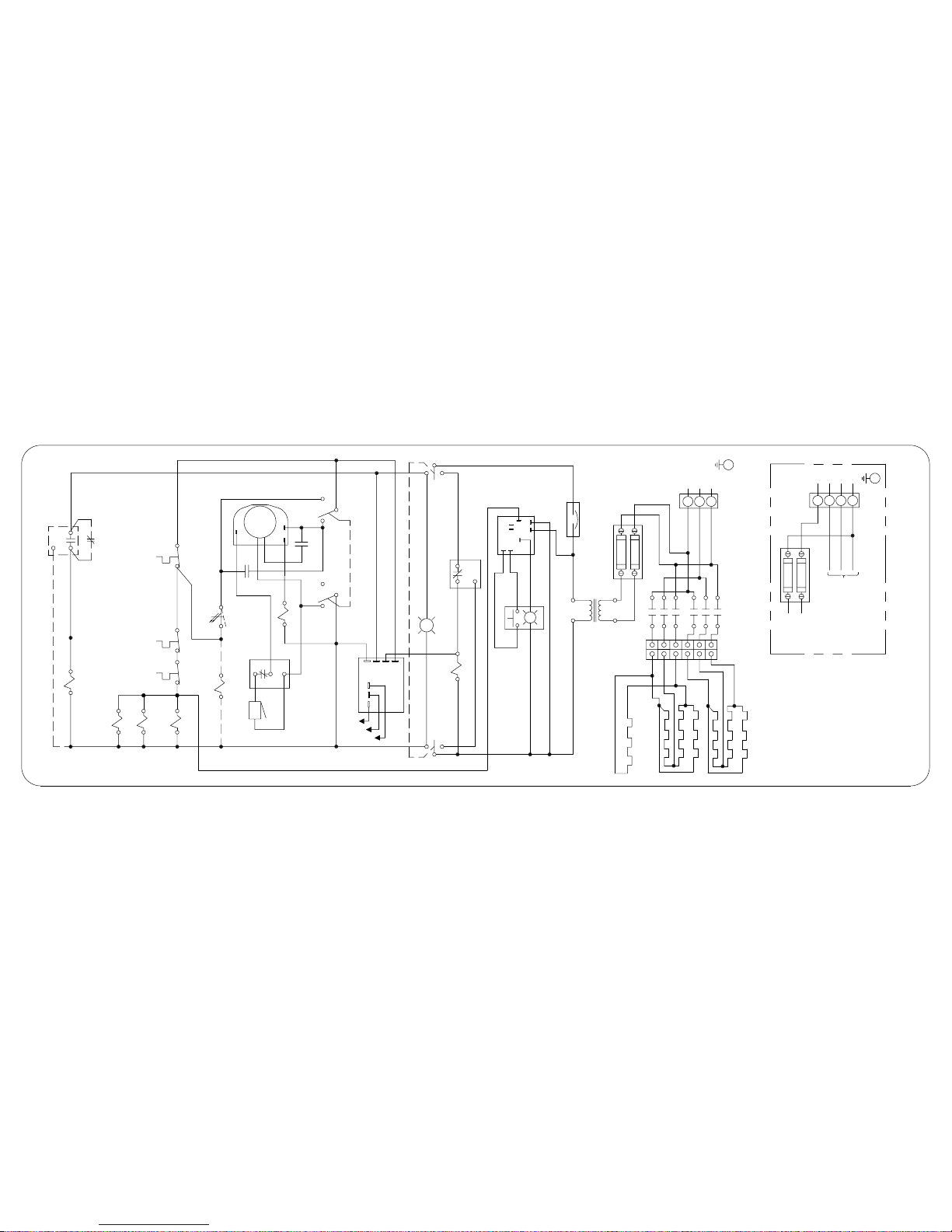
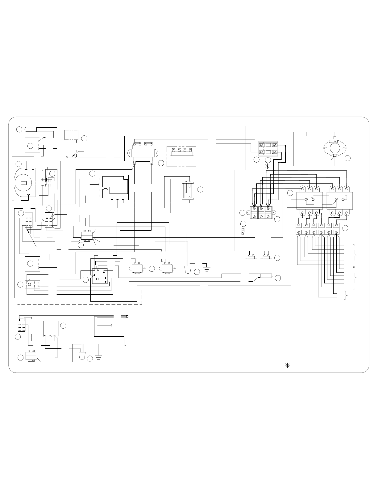
STEAMCRAFT 5.1 MECHANICAL TIMER
BREAKER
RESET CIRCUIT
2
8
4
7
TIMER
DESCALE
BLK
3
CONNECTION
3Ø
CUSTOMER
L3
L2
L1
TB
N
L3
L2
TB
L1
X2 SECONDARY
H1 PRIMARY
120V
L
NO
1
5
6
3
NO
A
L
X1
H4
FUSEBLOCK
FU
FU
TB
WHT
& RESET SWITCH
DESCALE INDICATOR
DRYING ELEMENT
FU
CONTACTORS
FU
TO H4
TO
380/415V 3Ø W / NEUTRAL
CUSTOMER CONNECTION
CONTACTORS
FUSEBLOCK
TO H1
HEATING ELEMENTS
TRANSFORMER
INTERMITTENT
CONTACTOR
TO
R1
C NC
R2
R2A
NC
MOTOR
C
NO
( OPT )
NO
SWITCH
R1
(SCS OPT)
C
DOOR
3
2
1
BUZZER
MANUALTIMEDMANUAL
NOC
R2B
3 SEC TIMER
TIMED
ELECTRO-MECHANICAL
TIMER
105966 - RELAY
UNITS )
109381 - FUSE, 1.5 A ( FOR 480 V
240 V UNITS )
109380 - FUSE, 3.5 A ( FOR 208 V &
109374 - FUSEBLOCK
101541 - TERMINAL BLOCK SECTIONAL
109240 - 6 POLE TERMINAL BLOCK
THERMAL SWITCH ( HSB )
TIMED/MANUAL
20
PRP
RED
8 N
27
WHT/RED
WHT/RED
PRP
1 32
11
RED
RED
GRN
WHT/RED
INTERMITTENT BLOWDOWN OPTION
WHT/RED
4
BLK
TAN
RED
TAN
WHT/GRA
3
3
2
1
WHT
5
ORN
87 5
BLU
8
3
4
2
1
6
BLK
BLK
WHT/BLU
WHT/RED
PARTS LIST
4 19994 - DESCALE INDICATOR RESET SW
105789 - THERMAL SWITCH ( HSB )
107241 - WATER BOARD
107239 - PROBE
44168 - TERMINAL BLOCK
108880 - DOOR SW (MAGNETIC)
106911 - DESCALE TIMER
22221 - DRAIN VALVE
( THRU SCS )
11
SWITCH
TO
TO
10
8
9
6
7
5
FILL
104224 - TIMED/MANUAL SWITCH
19993 - POWER SWITCH
20478 - 3 MIN TIMER
3
2
1
COND
PRP
12
RED
BLU
BLU
PRP
WHT/BLU
RED
11
GRN
15 103905 - CONTACTORS
106541 - INTMT BLOWDOWN TIMER
110198 - MOTORIZED TIMER
108331 - RESET CIRCUIT BREAKER
22
101540 - END SEGMENT
20304 - GROUND LUG
41350 - BUZZER
20477 - 3 SEC TIMER
21
20
19
17
18
16
27
26
25
24
103731 - HI LIMIT SWITCHES
22218 - WATER SOLENOIDS
20535 - TRANSFORMER
BLK
12
14
13
BLK
BLK
PRP
16
23
13
BLK
WHT/BLU
WHT
1
GRA
2
PNK
RED
N
WHT/RED
YEL
BLU
RED
ORN
HEATFILL H N
XL
YEL
10
17
19
BLK
BLK
2
1
3
6
BLU
RED
ORN
STEAMCRAFT 5.1 MECHANICAL TIMER
JUMPER POSITION
X1
X2
BLK
GRN
RED
HI
C
WHT
BLK
14
FOR 480 V
OPERATION
9
208/240
H3
120
H1 H2 H4
H3H1 H2 H4
BLK
BLK
25
26
BLK
CUSTOMER CONNECTION
21
22
WHT/RED
L1 L2 L3
23
21 34
BLK
15
ORN
FU
FU
YEL
HEATER
P106380 G
BOTTOM
WHT
RED
BLK
DRYING
ELEMENT
WHT
WHT
ELEMENTS
WHT
BLK
RED
WHT
BLK
RED
BLK
WHT
RED
TOP
65
24
WHT/BLK
7
HEAVY WIRE LINES INDICATES
NOTE:
12 AWG HI - TEMP WIRE
( SEE RATING PLATE )
DOOR SWITCH ( SCS )
REMOVED W / OPTIONAL
R2
LT BLU
18
NOC
NC
PNK
WHT/BLK
27
LT BLU
LT BLU
WHT/BLK
BLK
ORN/BLK
ORN
 Loading...