

Cleveland SGL -40-TR Installation Manual
SE95033 Rev. 5
1333 East 179th St., Cleveland, Ohio, U.S.A. 44110
Phone: (216) 481-4900 Fax: (216) 481-3782
Visit our web site at www.clevelandrange.com
Operators Manual
Installation, Operation & Service
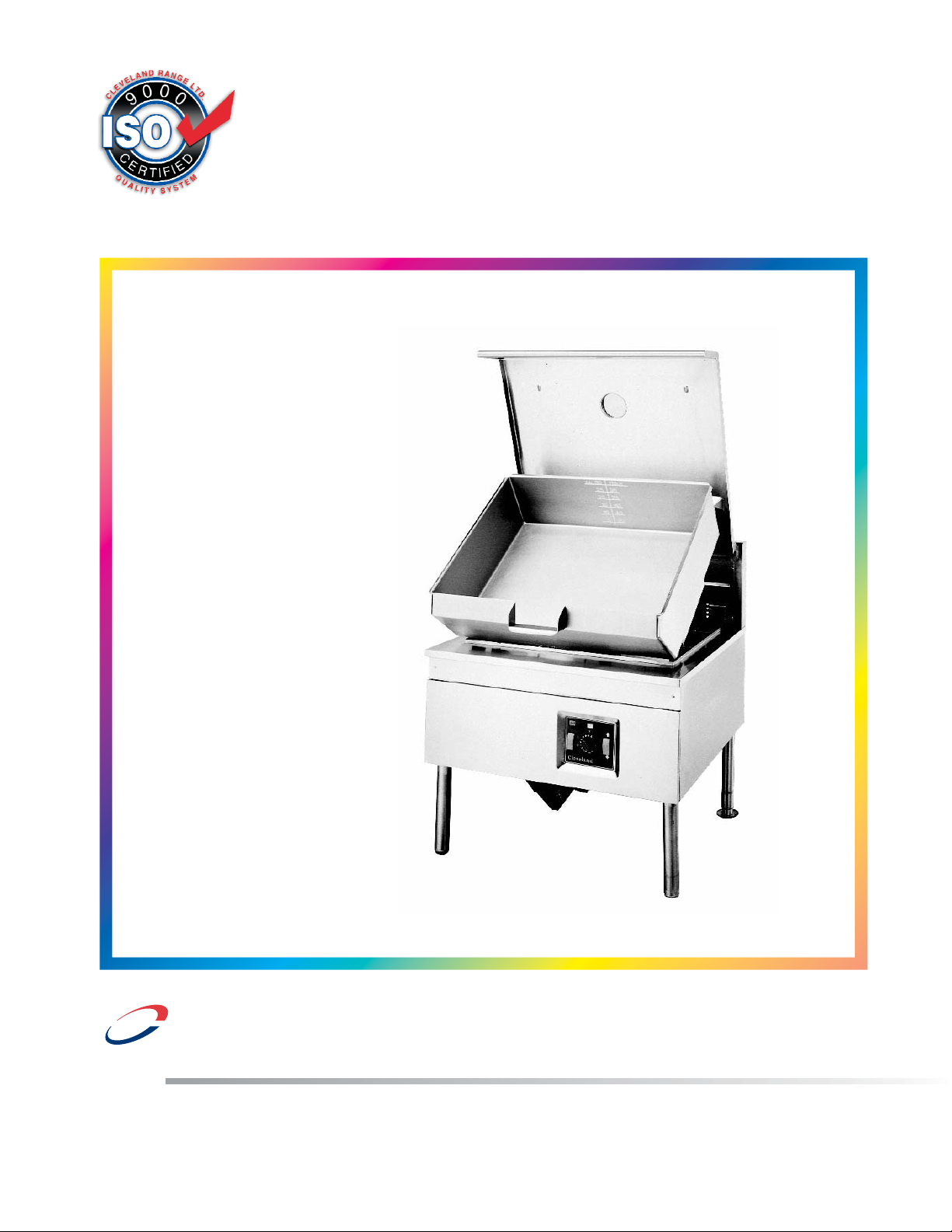
Skillets
d
Enodis
BULLET FOOT (FRONT) 078160-1
FLANGED FOOT (BACK) 078161-1
sk2335499
SK2336800
SIDE PANEL; SEL/SGL-TR
SK2457196-40 GAL
SK2457197-30 GAL
OPEN BASE & MODULAR
GAS SKILLETS -
MODELS
SGL-30-TR SGM-30-TR
SGL-40-TR SGM-40-TR
™
Clev elan
FOR THE USER
IMPORTANT
Post in a prominent location, instructions to be followed in the event the user smells gas.
This information shall be obtained by consulting your local gas supplier.
Keep appliance area free and clear from combustibles.
Do not obstruct the flow of combustion and ventilation air.
All service must be performed by a qualified cleveland range technician.
For unit equipped with casters, the installation shall be made with a connector that complies
with the Standard for Connectors for Movable Gas Appliances, ANSI Z21.69 or Connectors
for Moveable Gas Appliances, CAMCGA-6.16, and a quick-disconnect device that complies
with the Standard for Quick Disconnect Devices for Use With Gas Fuel, ANSI Z21.41, or
Quick Disconnect Devices for Use with Gas Fue4 CANT-6.9. Adequate means must be
provided to limit the movement of the appliance without depending on the connector and the
quick-disconnect device or its associated piping to limit the appliance movement. A restraint
can be attached to the rear leg next to the gas connection.
For Australia, the equipment must be installed by an authorized person in accordance with
AS 5601, local authority, gas, electricity, any applicable statutory regulations and
manufacturer requirements.
RETAIN THIS MANUAL FOR YOUR REFERENCE.
WARNING: Improper installation,
adjustment, alteration, service or
maintenance can cause property
damage, injury or death. Read the
Installation and Operating
instructions thoroughly before
installing or servicing this
equipment.
FOR YOUR SAFETY
DO NOT STORE OR USE
GASOLINE OR ANY OTHER
FLAMMABLE LIQUIDS AND
VAPOURS IN THE VICINITY
OF THIS OR ANY OTHER
APPLIANCE.
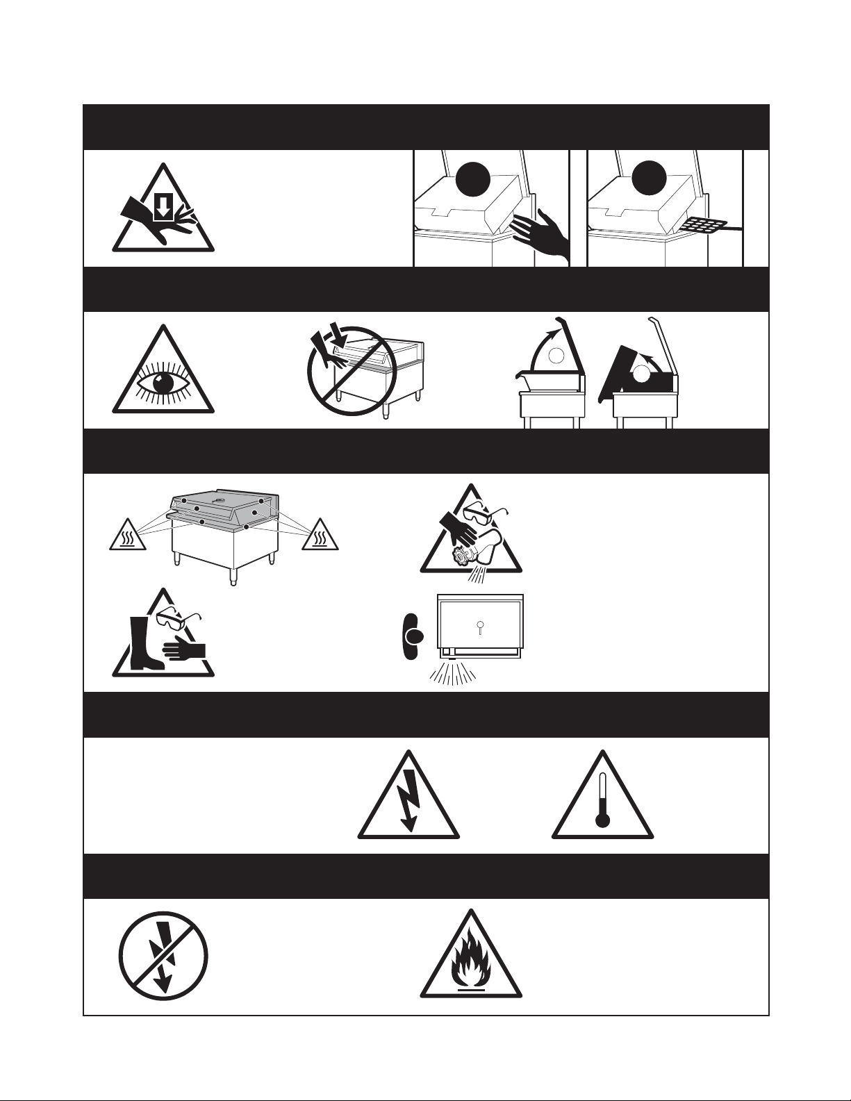
For your safety
DANGER
Keep hands and utensils
away from moving parts and
pinch points.
IMPORTANT
Inspect unit
daily for
proper
operation.
CAUTION
✘
Do not lean
on or place
objects on
skillet lip.
✘
1
2
Wear protective equipment when
discharging hot product.
Lift lid
before
tilting
skillet.
Surfaces may be
extremely hot! Use
protective equipment.
SERVICING
WARNING: Improper installation, adjustment,
alteration, service or maintenance can cause
property damage, injury or death. Read the
installation, operating and maintenance
instructions thoroughly before installing
or servicing this equipment.
GAS APPLIANCES
Do not attempt to operate
this appliance during a
power failure.
Stand clear of product
discharge path when
discharging hot product.
Shut off power
at main fuse
disconnect
prior to
servicing.
Keep appliance and area free
and clear of combustibles.
Ensure skillet
is at room
temperature
prior to
servicing.

GENERAL
Installation of the unit must be accomplished by
qualified installation personnel working to all applicable
local and national codes. Improper installation of unit
could cause injury or damage.
This equipment is built to comply with applicable
standards for manufacturers. Included among those
approval agencies are: UL, A.G.A., NSF, ASME/N.Bd.,
CSA, CGA, ETL, and others. Many local codes exist,
and it is the responsibility of the owner/installer to
comply with these codes.
The rating plate is located directly behind the upper
front panel (left side). For easy access, remove the two
screws securing the upper front panel and hinge the
lower front panel downwards. Gas type, burner ratings
and electrical requirements are stated on the plate.
Observe all clearance requirements to provide proper
make-up air flow. Do not obstruct the flow of combustion
and ventilation air. Check rating plate to ensure that unit
has been equipped to operate with the type of gas
available at the installation.
All units are protected with fuses which are located
inside the service box. For easy access, hinge front
panel downwards.
A pressure tap is supplied with each unit and is
installed on the manifold. The gas pressure must be
checked when unit is installed, to ensure unit gas
pressure is the same as specified on the rating plate.
For access to the pressure tap, remove front panel, turn
power switch to the 'OFF' position as a precaution and
hinge front panel downwards. The pressure tap is
located behind the front shield. If necessary, pressure
adjustments can be made at the pressure regulator
which is installed on the manifold. For easy access to
the pressure regulator, view along left side of unit from
underneath. Once pressure test is completed, turn
power switch and thermostat to the 'OFF' position. Raise
lower front panel back into position.
Make certain that new piping, joints and connections
have been made in a clean manner and have been
purged, so that piping compound, chips, etc., will not
clog valves and/ or controls. Use pipe joint sealant that
is approved for use with liquefied petroleum gas.
Have a qualified gas technician check the gas pressure
to make certain that existing gas facilities (meter, piping;
etc.) will deliver the BTU's of gas required at the unit
with no more than 1/2" water column pressure drop.
When checking pressure, be certain that all the
equipment on the same gas line is turned to the 'ON'
position.
WARNING: Always check gas connections for leaks
using soap solution or similar means. DO NOT CHECK
WITH AN OPEN FLAME.
INSPECTION
Before unpacking visually inspect the unit for evidence
of damage during shipping.
If damage is noticed, do not unpack the unit, follow
shipping damage instructions.
SHIPPING DAMAGE
INSTRUCTIONS
If shipping damage to the unit is discovered or
suspected, observe the following guidelines in
preparing a shipping damage claim.
1. Write down a description of the damage or the
reason for suspecting damage as soon as it is
discovered. This will help in filling out the claim
forms later.
2. As soon as damage is discovered or suspected,
notify the carrier that delivered the shipment.
3. Arrange for the carrier's representative to examine
the damage.
4. Fill out all carrier claims forms and have the
examining carrier sign and date each form.
CLEARANCE
REQUIREMENTS/ DRAIN
LOCATIONS
This unit must be installed in accordance with the
clearances shown on the rating label which is adhered
to the unit.
FOR YOUR SAFETY. Keep the appliance area free and
clear of combustible materials.
VENTILATION
These units must be installed under an adequate
ventilation system.
INSTALLATION
INSTALLATION
KEEP THE APPLIANCE AREA FREE AND CLEAR OF
COMBUSTIBLE MATERIALS.
1. Carefully remove unit from carton or crate. Remove
any packing material from unit.
2. A protective material has been applied to the
stainless steel panels.
NOTE: This material must be removed immediately
after installation, as heat will melt the material and
make it difficult to remove.
3. Position the unit in it's permanent location.
4. Level skillet by means of adjustable stainless steel
feet. Use a spirit level and level unit four ways;
across front and back and down left and right edges.
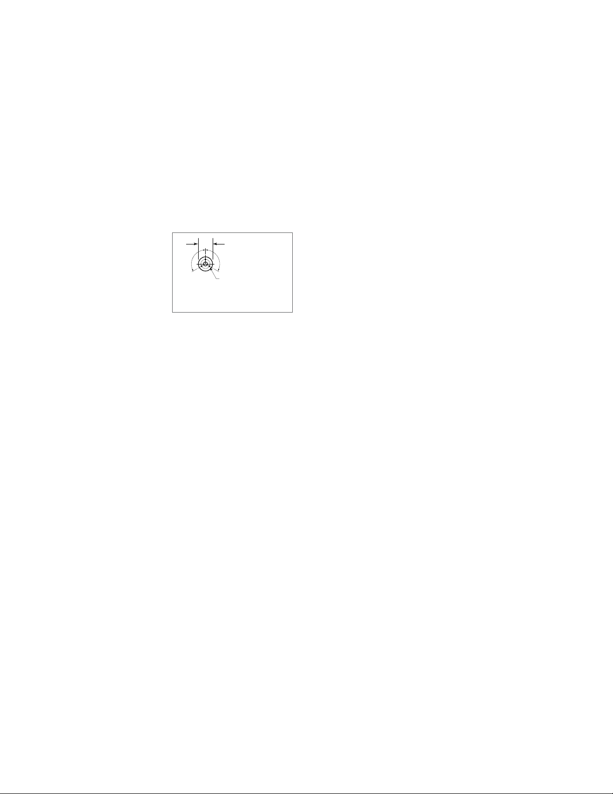
5. Once positioned and
leveled, permanently
secure the unit's
flanged feet to the
floor using 5/16" lag
bolts
and floor
anchors (supplied by
the installer). Three
bolts are required to secure each of the flanged feet
.
6. Seal joints of flanged feet with a silicone sealant.
GAS
ENSURE THE GAS SUPPLY MATCHES THE
SKILLET'S REQUIREMENTS AS STATED ON THE
RATING PLATE.
A 3/4" NPT gas connection is required along the left
side of the unit.
It is recommended that a sediment trap (drip leg) be
installed in the gas supply line. If the gas pressure
exceeds 14" water column, a pressure regulator must
be installed, to provide a maximum of 14" water column
gas pressure to the gas control valve.
Connect the gas supply piping. Location and pressure
data are shown on the specification sheet.
Installation must be in accordance with local codes
and/or the National Fuel Gas Code ANSI Z233.1-latest
edition (USA) or Installation Codes for Gas Burning
Appliances and Equipment CAN/CGA-B 149.1 and B
149.2 (Canada). Use a gas pipe joint compound which
is resistant to L.P gas. Test all pipe joints for leaks with
soap and water solution. Ensure that the gas pressure
regulator is set for the manifold pressure indicated on
the gas rating plate.
The appliance and its individual shut-off valve must be
disconnected from the gas supply piping system during
any pressure testing of that system at test pressures in
excess of 1/2 psi (3.45 kPa). The appliance must be
isolated from the gas supply piping system by closing
its individual manual shut-off valve during any pressure
testing of the gas supply piping system at test
pressures equal to or less than 1/2 psi (3.45 kPa).
VENTILATION
A gas skillet must be installed in a location in which the
facilities for ventilation permit satisfactory combustion of
gas and proper venting. Proper ventilation is imperative
for good operation of the appliance. The ideal method
of ventilating a gas skillet is the use of a properly
designed ventilating canopy, which should extend at
least 6" (152mm) beyond all sides of the appliance
(except against a wall, if the canopy is a wall
installation). This is usually part of a mechanical exhaust
system.
Further information can be obtained by referring to the
U.S.A. National Fire Protection Association's NFPA96
regulations. These standards have also been adopted
by the National Building Code in Canada.
AIR SUPPLY
Unit shall be located so as not to interfere with proper
circulation of air within the confined space. All gas
burners require sufficient air to operate.
Large objects should not be placed in front of the unit
which might obstruct the air flow through the front. Do
not obstruct the flow of combustion and ventilation air.
Do not permit fans to blow directly at the unit and
wherever possible avoid open windows adjacent to the
appliance sides and back; also wall type fans which
create air crosscurrents within the room.
ELECTRICAL
A cord and plug is supplied on each unit, 120 volts,
single phase, 1.0 amps.
WARNING: Electrical Grounding Instructions:
This appliance is equipped with a three prong
(grounding) plug for your protection against shock
hazard and should be plugged directly into a properly
grounded three prong receptacle. Do not cut or remove
the grounding prong from this plug.
A separate 15 amp service must be provided. For 120V
usage, each skillet is electrically equipped with a cord
set with a three prong plug which fits any standard 120
volt three prong grounded receptacle.
When a unit is ordered and built for 208/240 volt, the
supply line must be connected to the wiring
terminations located inside the terminal box. For ease in
attaching the supply line, there is a removable cover on
the terminal box. A wiring diagram is attached to the
rear panel of each unit.
IMPORTANT: This appliance must be electrically
grounded in full accordance with local codes, or in the
absence of local codes, with the Canadian Electrical
Code C22.1 or with the National Electrical Code,
ANSI/NFPA No. 70-latest edition (whichever is
applicable).
7/16"Ø, 3 HOLES
ON 3 1/8" (80mm) B.C.D.
FLANGED FOOT DETAIL
(REAR LEGS ONLY)
120 120
4 7/8" (124mm)
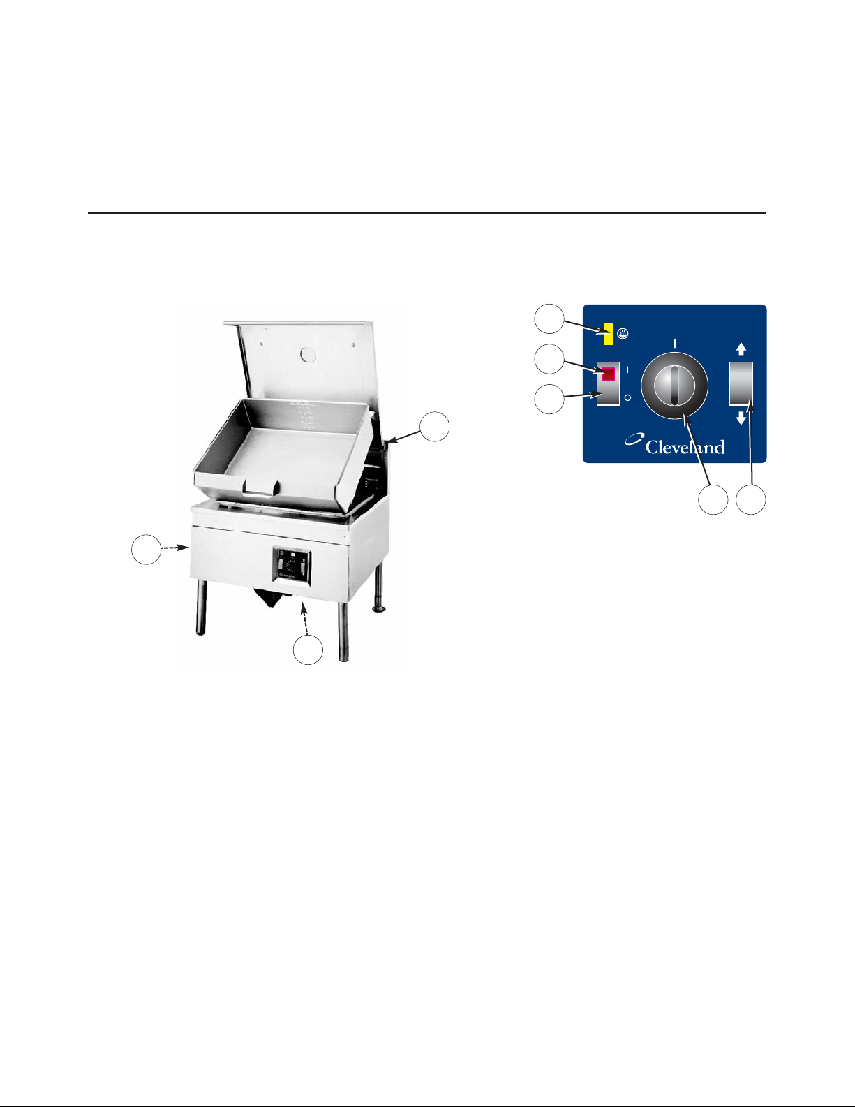
CONTROL
PANEL
OPERATING INSTRUCTIONS
ITEM # DESCRIPTION FUNCTION
1. On-Off Switch Main power switch for unit.
2. Power Indicator Light (Red) Indicates power is on.
3. Heat Indicator Light (Yellow) Turns ON when system is calling for heat and
OFF when system is satisfied.
4. Temperature Dial Regulates the surface temperature of the pan.
5. Power Tilt Switch Used for tilting the pan up or down.
Some models have a Hand Tilt Wheel.
6. Manual Tilt Override Used on units with Power Tilt for tilting the pan up or down
in case of power or mechanical failure.
7. Flue
8. Gas Shut Off Valve Allows you to shut the gas off to the appliance if required.
9. Tangent Draw-Off Valve Option - Used for draining product or wash water from kettle.
(not shown)
10. Faucet Option - hot and/or cold faucet mounts to skillet for
(not shown) convenient filling of the pan.
xttwulql
3
2
1
4 5
7
8
6
WATER CONNECTIONS
(OPTIONAL)
A 3/8" NPT cold water line and a 3/8" NPT hot water line
are required for the fill faucet.
CLEANING
After installation the unit must be thoroughly cleaned
and sanitized prior to cooking.

START UP PROCEDURE
This appliance has been factory tested and adjusted
under ideal conditions but, rough handling, low gas
pressure, altitude or variations in gas characteristics
may require fine adjustment.
All units are equipped with fixed orifices and do not
require primary air adjustment.
LIGHTING INSTRUCTIONS
NOTE: This appliance is equipped with a direct spark
ignition system. Ensure gas and electrical supply to the
appliance, are in the 'ON' position.
1. Turn the main manual gas shut-off valve to the 'ON'
position.
2. Turn power switch to the 'ON' position.
3. Set thermostat to desired temperature.
4. If ignition fails and/or the control system goes into
lockout, set power switch to the 'OFF" position.
5. Wait 5 minutes then repeat steps 1 through 3. If the
problem persists, have a qualified serviceman
check the system.
6. To shutdown system, turn power switch and main
manual gas valve to the 'OFF' position.
OPERATING INSTRUCTIONS
1. Ensure gas and electrical supply to the appliance
are in the 'ON' position.
2. Turn power switch to the 'ON' position. The green
pilot light will indicate power is on. Wait one minute
to allow flame sensor to heat up.
3. TILTING OPTIONS
Note: Before tilting the pan make sure the lid is
open.
PowerTilt
Cleveland skillets are equipped with an electric
power tilt mechanism for raising and lowering the
frypan. To raise frypan, raise the cover and press up
on the tilt switch. To lower frypan, press down on the
tilt switch.
Manual Tilt
Cleveland skillets can also be equipped with the
optional manual tilt mechanism for raising and
lowering the frypan. To raise frypan, raise the cover
and turn the wheel clockwise. To lower frypan, push
in on the lever located behind the wheel.
4. FOR YOUR SAFETY, this skillet is also equipped
with a power interrupter which automatically shuts
off the gas supply to the burners whenever the
skillet is raised more than 1/2" (13mm).
5. Turn power switch to the 'OFF' position when skillet
is not in use.
6. During an electrical power interruption, turn power
switch to the 'Off position. This unit cannot be made
to operate without electrical power or gas supply.
OPERATING SUGGESTIONS
IMPORTANT: Always raise the spring assist cover
before activating the tilt mechanism. Before
commencing to cook, ensure frypan is in the lowered
position by pressing down on the tilt switch.
1. To preheat, set thermostat to desired cooking
temperature. The amber pilot light will cycle on and
off with the thermostat.
2. Allow skillet to preheat for approximately 15-30
minutes.
3. Once preheated, insert product in skillet and adjust
thermostat to required cooking temperature.
4. If desired, once product has cooked, it can be held
prior to serving at a lower temperature setting.
5. When cooking is completed, set thermostat and
power switch to the 'OFF' position.
6. The best time to clean the skillet is immediately after
use, once skillet has cooled down.
 Loading...