

Cleveland SGL-30-X Service Manual
Repair Manual
Free Standing
Gas Skillets
Models SGM-X
SGL-X

OPERATING CONTROLS
(Electrical
Timer Control Knob
This
knob controls the bell timer and allows the
Tilt Switch
When activated this switch will raise or lower the
Push Button
AND INDICATORS
For your better understanding and confidence, the following explanation of the control system used on
these skillets is offered.
Item No. Description Function
2
4
7
9
15
13, 17
12, 16
10
27
Gas Control Valve 13
(Skillet Bottom Dwg.)
Pilot Light When illuminated, the lower pilot light indicates
(Electrical electrical power is on to the skillet and the upper pilot
Components Dwg.) light indicates the main gas burners are on.
Thermostat Control Knob This control knob allows the operator to select various
(Electrical
Components Dwg.)
On/Off Toggle Switch
Components Dwg.)
(Electrical operator to select a time interval after which a bell
Components Dwg.) will sound.
(Electrical
Components Dwg.)
Hand Wheel
(Hydraulic Lift
Mechanism Dwg.)
(Hydraulic Lift
Mechanism Dwg.)
Micro Switch Protective switch to prevent burners from igniting
(Electric Jack
Assembly Dwg.)
Micro Switch Protective switch to prevent burners from igniting
(Hydraulic Jack
Assembly Dwg.)
Controls main gas supply to the skillet.
heat increments for operating the skillet
Controls electrical power to the skillet
skillet pan.
Turn counter -clockwise to raise skillet pan.
Press to allow skillet pan to lower.
white skillet pan is in a raised position.
write skillet pan is in a raised position.
1
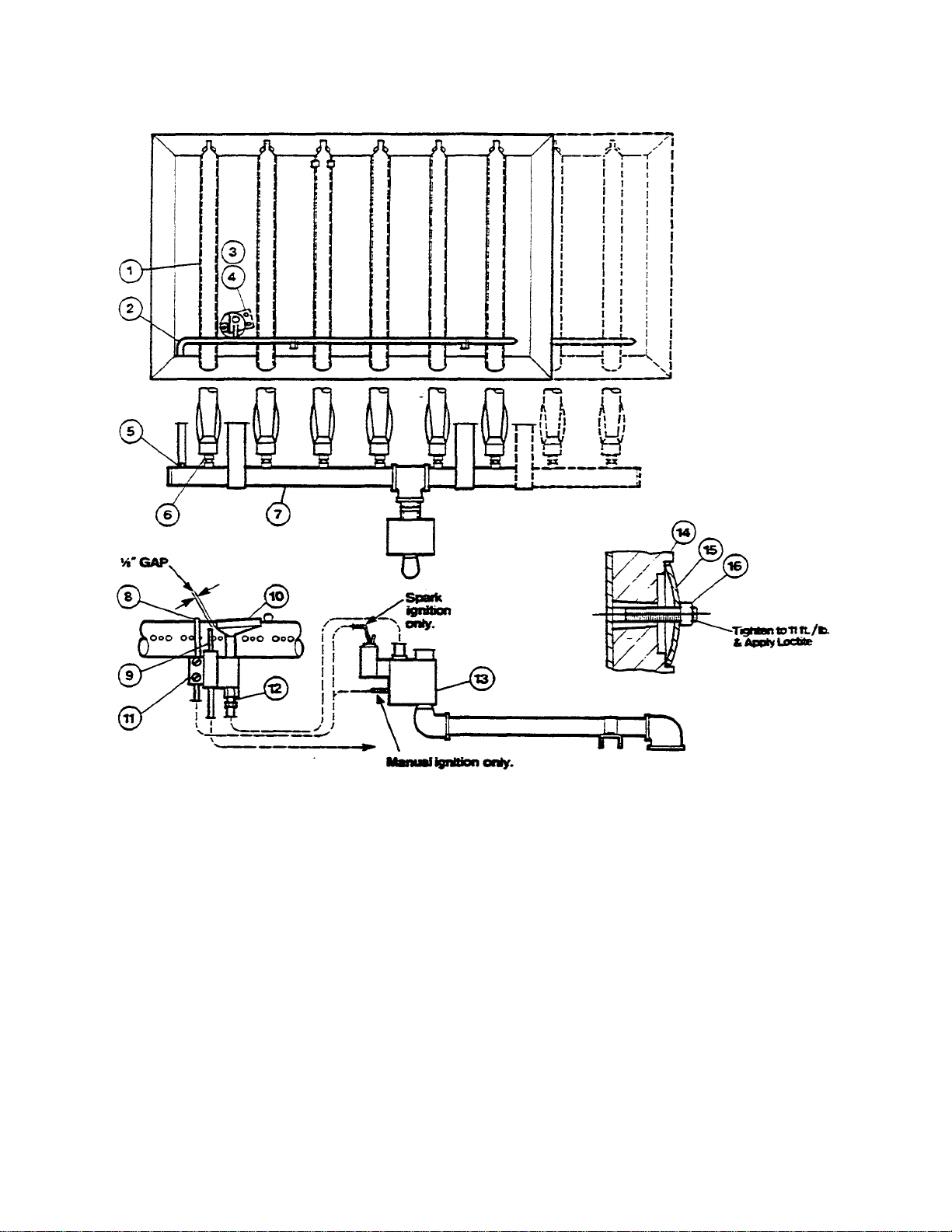
PARTS LIS T - SKILLET BOTTOM
Item No. Part No. Description Qty.
1 SK50502 Burner 6,8
2 SK50520 Zip Tube (SGL, SGM -30-X) 1
3 SK50553 Bracket, Pilot Mounting 1
4 FA10360 Screw. 10-32 x 1/4" 2
5 SK50363 Orifice, Zip Tube, Natural Gas 1
SK50521 Zip Tube (SGL, SGM -40-X) 1
SK50669 Orifice, Zip Tube, Natural Gas 1
SK50671 Orifice, Zip Tube, Natural Gas 1
SK50364 Orifice, Zip Tube, L.P. 1
SK50670 Orifice, Zip Tube, L.P. 1
SK50672 Orifice, Zip Tube, L.P. 1
(0-2000 Ft Elev . #61 Drill)
(2000-4000 Ft Elev . #62 Drill)
(4000-6000 Ft Elev . #63 Drill)
(0-2000 Ft Elev . #72 Drill)
(2000-4000 Ft Elev . #73 Drill)
(4000-6000 Ft Elev . #74 Drill)
2

6 SK50503 Orifice, Burner, Natural Gas 6,8
(0-2000 Ft. Elev. #52 Drill)
SK50505 Orifice, Burner, Natural Gas 6,8
(2000-4000 Ft. Elev. #1/16 Drill)
SK50507 Orifice, Burner, Natural Gas 6,8
(4000-6000 Ft Elev. #53 Drill)
SK50504 Orifice, Burner, L.P. 6,8
(0-2000 Ft. Elev. #57 Drill)
SK50506 Orifice, Burner, L.P. 6,8
(2000-4000 Ft. Elev. #58 Drill)
SK50508 Orifice, Burner, L.P. 6,8
(4000-6000 Ft. Elev. #59 Drill)
7 SK00192 Manifold, Burner (SQL SGM-30-X) 1
SK00193 Manifold, Burner (SGL SGM-40-X) 1
8 KE51111 Pilot name Sensor 1
(Thermopile Type) (Manual Ignition)
KE51159 Pilot Flame Sensor 1
(Mercury Vapour Type) (Spark Ignition)
9 KE01016 Ignition Electrode (Spark Ignition) 1
10 KE51114 Pilot Burner 1
11 KE51115 Holder, Pilot Flame Sensor 1
(Manual Ignition)
12 KE51116 Orifice, Pilot, Natural Gas (.020") 1
KE51162 Orifice, Pilot, L.P. (.0145") 1
13 KE51155 Combination Gas Control Valve, Natural 1
Gas, 24 VAC (Spark Ignition)
KE51163 Combination Gas Control Valve, L.P., 1
24 VAC (Spark Ignition)
SK50608 Combination Gas Control Valve, Natural 1
Gas, 24 VAC (Manual Ignition)
SE00043 Combination Gas Control Valve, L.P., 1
24 VAC (Manual Ignition)
KE51110 Combination Gas Control Valve, Natural 1
Gas, 120 VAC (Manual Ignition)
KE51161 Combination Gas Control Valve, L.P., 1
120 VAC (Manual Ignition)
14 SK50249 Heat Spreader (R.H. End Piece) 1
SK50531 Heat Spreader (L.H. End Piece) 1
SK50532 Heat Spreader (with Thermostat cut-out) 1
SK50213 Heat Spreader (Plain) 3,5
15 SK50416 Washer. Spherical 28,36
16 FA21024 Nut, 5/16-18 28,36
Use only replacement parts which are factory supplied as to preserve the certification of Underwriters Laboratories,
American Gas Association, Canadian Standards Association or Canadian Gas Association (as applicable). The use
of other than factory supplied replacement parts will void the warranty.
3
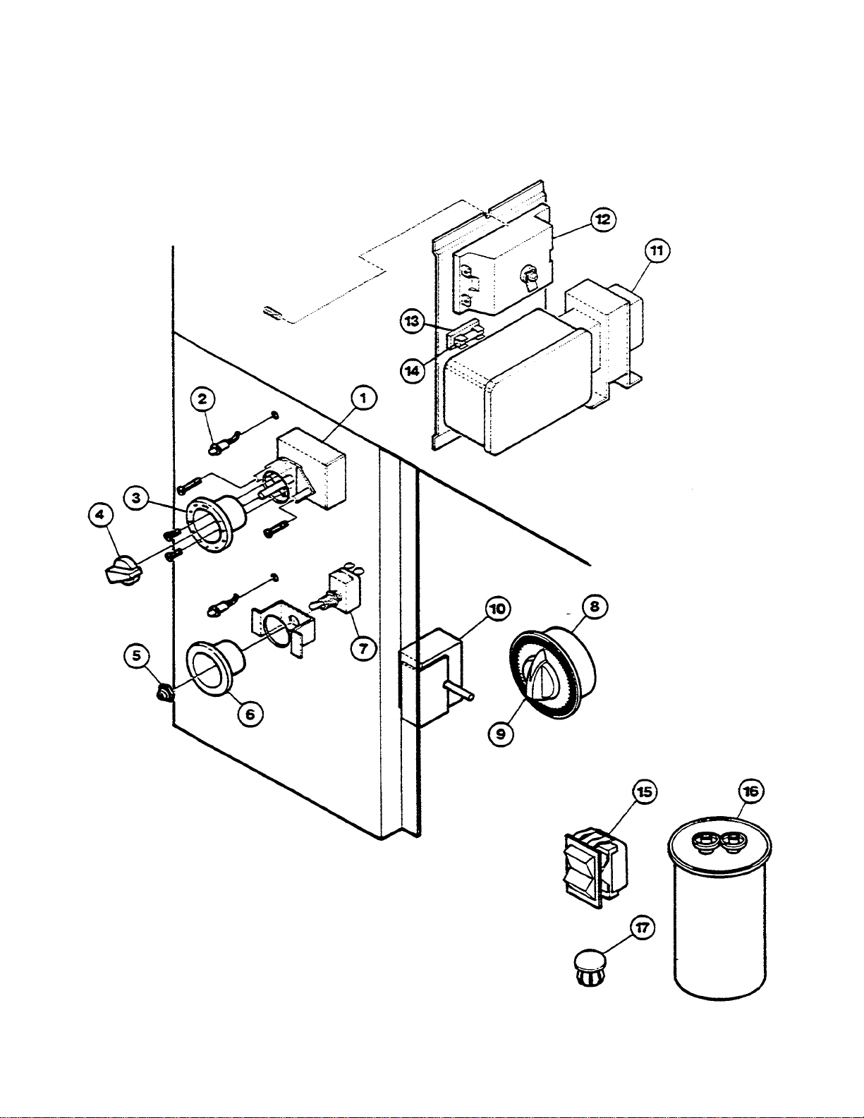
ELECTRICAL COMPONENTS
4

PARTS LIS T - ELECTRICAL COMPONENTS
Item No. Part No. Description Qty.
1 SK50606 Thermostat, Operating (230°C) 1
2 SK50539 Pilot Light 2
3 SK00031 Bezel, Thermostat (°F) 1
4 SK50059 Knob, Thermostat 1
5 SK50062 Rubber Boot 1
6 SK50540 Bezel, ON/OFF Switch 1
7 KE50504 Switch, Toggle, ON/OFF, SPST 1
8-9 SK50725 Timer 1
9 11301 Knob, Timer 1
10 SK50607 Thermostat, Safety (280°C) 1
11 KE51164 Transformer, 120/24 V 1
12 KE51167 Pilot Re-Lite (Nat Gas) 1
13 KE51139 Fuse Holder 1
14 KE51169 Fuse, 1 1/2 Amp (Spark Ignition) 1
15 SK50680 Switch, Rocker, Momentary 1
16 SK50728 Capacitor, 20 MFD (Silver, Metal) 1
16a
16b
17 SK50397 Plug Button 1
SK00180 Bezel, Thermostat (°C) 1
KE51405 Pilot Re-Lite and Cycling 1
KE51140 Fuse, 4/10 Amp (Manual Ignition) 1
Pilot Safety Timer Combination
(L.P. Gas)
Capacitor, 30 MFD (Silver Metal) 1
(Please order Item No. 16)
Capacitor, 27-32 MFD (Black, 1
Plastic) (Please order Item No. 16
and See Note)
Note: When replacing this capacitor, the original mounting clip must be broken off, two holes
drilled in the mounting box and a tie wrap used to hold the new capacitor.
Use only replacement pans which are factory supplied as to preserve the certification of Underwriters Laboratories,
American Gas Association, Canadian Standards Association or Canadian Gas Association (as applicable). The other than
factory supplied replacement parts will void the warranty.
5
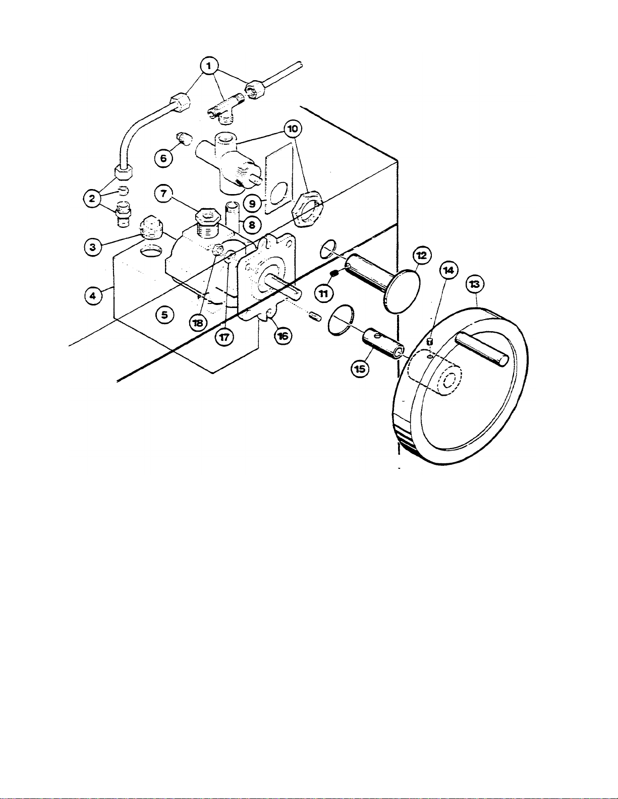
PARTS LIS
T -
HYDRAULIC LIF
T
MECHANISM
(PRIOR TO APRIL 1,1988)
Item No. Part No. Description Qty.
1 FI05048 Tee 1
2 FI05132 Ballcheck Connector 1
3 SK50557 Plug, 3/4" NPT 1
4 SK00191 Oil Tank 1
5 SK50715 Motor Oil, SAE 30 1L/1 Qt
6 FI00236 Plug, 1/4" NPT 1
7 FI00350 Reducer Bushing 1
8 FI05133 Pipe 1
9 SK50604 Bracket, Relief Valve 1
10 SK50603 Relief Valve 1
11 FA19060 Set Screw, #8-32 x 1/8" 1
12 SK00241 Push Button 1
13-14 KE00508 Hand Wheel 1
14 FA19501 Set Screw, 3/8- 16 x 3/8" 1
15 SK50556 Bushing, Hand Wheel 1
16 SK50602 Hydraulic Pump 1
17 FA31009 Lockwasher, 5/16 2
18 FA20010 Hex Nut, 5/16-18 2
Use only replacement parts which are factory supplied as to preserve the certification of Underwriters Laboratories,
American Gas Association, Canadian Standards Association or Canadian Gas Association (as applicable). The use of
other than factory supplied replacement parts will void the warranty.
6
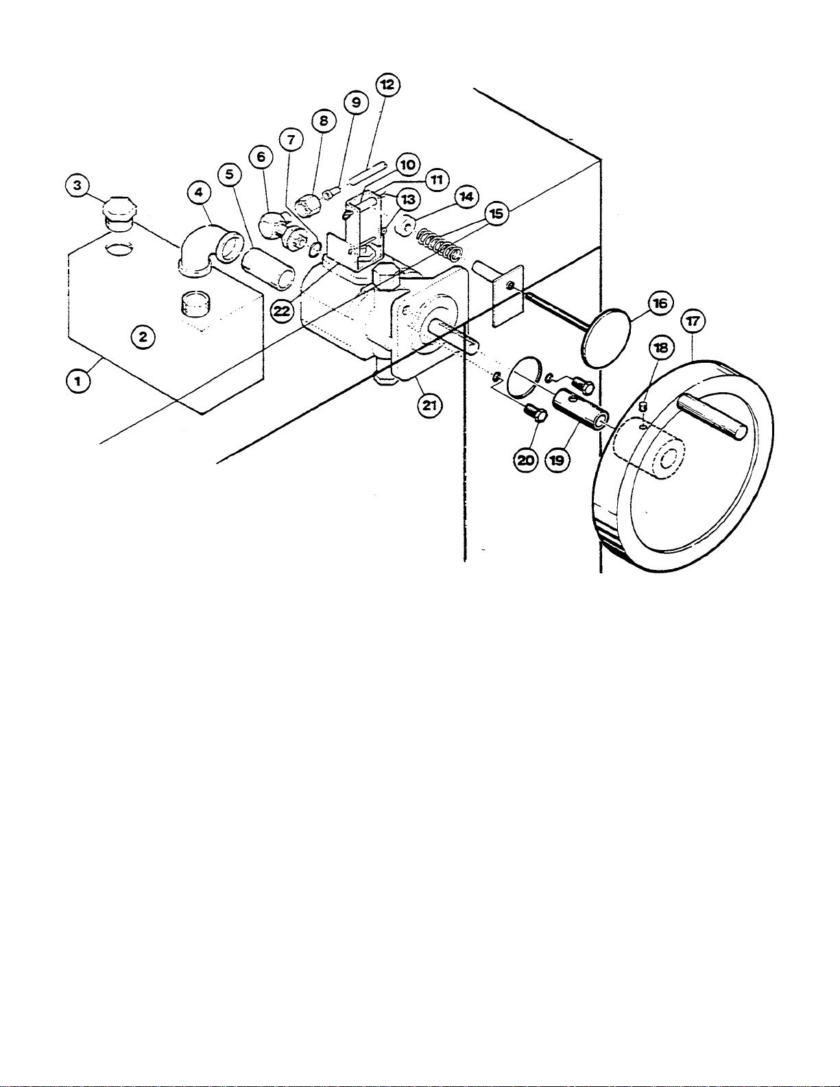
PARTS LIST
- HYDRAULIC LIFT MECHANISM
(AFTER APRIL 1,1988)
Item No. Part No.
Description
Qty.
1 SK00191 Oil Tank 1
2 SK50715 Motor Oil, SAE 30 1L/1 Qt.
3 SK50557 Plug, 3/4" NPT 1
4 FI00051 Elbow, 1/2" NPT 1
5 FI00587 Pipe, 1/2" NPT x 2 1/2" 1
6-7 FI05140 Elbow 1
7 SE50239 "O" Ring 1
8 FI05139 Nut, 7/16 - 20 Std. Thread 1
9 FI05138 Sleeve 1
10 SK50666 Roller 1
11 SK50604 Bracket, Relief Valve 1
12 SK50628 On Tubing, 77" (SGL-30-X) 1
SK50629 Oil Tubing, 88 1/4" (SGL-40-X) 1
SK50630 On Tubing, 86 1/2" (SGM -30-X) 1
SK50631 Oil Tubing, 97 3/4" (SGM-40-X) 1
13 FA95029 Cotter Pin, 1/8" Dia. x 11/2" 2
14 SK50667 Threaded Slug 1
15 SK50677 Spring 1
16 SK00241 Push Button 1
17-18 KE00508 Hand Wheel 1
18 FA19501 Set Screw. 3/8 -16 x 3/8" 1
19 SK50556 Bushing, Hand Wheel 1
20 FA10753 Bolt 3/8-24 x 1" 2
21 SK50679 Hydraulic Pump 1
22 SK50558 Bracket, Relief Valve 1
7
 Loading...