

Cleveland SGL-30-T1 Installation Manual
SE95050 Rev. 6
Operators Manual
Installation, Operation & Service
Gas T1 Skillets
1333 East 179th St., Cleveland, Ohio, U.S.A. 44110
Phone: (216) 481-4900 Fax: (216) 481-3782
Visit our web site at www.clevelandrange.com
d
FOR MODELS
BUILT AFTER
MAY 2006:
SGL-30-T1
SGL-40-T1
Enodis
For a complete Service Manual
refer to www.clevelandrange.com
™
Clev elan
FOR THE USER
IMPORTANT
Post in a prominent location, instructions to be followed in the event the user smells gas.
This information shall be obtained by consulting your local gas supplier.
Keep appliance area free and clear from combustibles.
Do not obstruct the flow of combustion and ventilation air.
All service must be performed by a qualified cleveland range technician.
For unit equipped with casters, the installation shall be made with a connector that complies
with the Standard for Connectors for Movable Gas Appliances, ANSI Z21.69 or Connectors
for Moveable Gas Appliances, CAMCGA-6.16, and a quick-disconnect device that complies
with the Standard for Quick Disconnect Devices for Use With Gas Fuel, ANSI Z21.41, or
Quick Disconnect Devices for Use with Gas Fue4 CANT-6.9. Adequate means must be
provided to limit the movement of the appliance without depending on the connector and the
quick-disconnect device or its associated piping to limit the appliance movement. A restraint
can be attached to the rear leg next to the gas connection.
RETAIN THIS MANUAL FOR YOUR REFERENCE.
WARNING: Improper installation,
adjustment, alteration, service or
maintenance can cause property
damage, injury or death. Read the
Installation and Operating
instructions thoroughly before
installing or servicing this
equipment.
FOR YOUR SAFETY
DO NOT STORE OR USE
GASOLINE OR ANY OTHER
FLAMMABLE LIQUIDS AND
VAPOURS IN THE VICINITY
OF THIS OR ANY OTHER
APPLIANCE.
GENERAL
Installation of the unit must be accomplished by
qualified installation personnel working to all applicable
local and national codes. Improper installation of
product could cause injury or damage.
This equipment is built to comply with applicable
standards for manufacturers. Included among those
approval agencies are: UL, A.G.A., NSF, ASME/N.Bd.,
CSA, CGA, ETL, and others. Many local codes exist,
and it is the responsibility of the owner/installer to
comply with these codes.
Observe all clearance requirements to provide proper
make-up air flow. Do not obstruct the flow of combustion
and ventilation air. Check rating plate to ensure that unit
has been equipped to operate with the type of gas
available at the installation.
Dimensions and clearance requirements are shown on
the Specification Sheet.
INSPECTION / UNPACKING
1. Before unpacking visually inspect the unit for
evidence of damage during shipping.
2. If damage is noticed, do not unpack the unit, follow
"SHIPPING DAMAGE INSTRUCTIONS" shown below.
3. Carefully remove unit from shipping carton. Remove
any packing material from unit. After carefully
unpacking check for "concealed" damage. If
damage is noticed, follow "SHIPPING DAMAGE
INSTRUCTIONS" shown below.
4. A protective material has been applied to the
stainless steel panels. This material must be
removed immediately after installation, as heat will
melt the material and make it more difficult to
remove.
SHIPPING DAMAGE
INSTRUCTIONS
If shipping damage to the unit is discovered or
suspected, observe the following guidelines in
preparing a shipping damage claim.
1. Write down a description of the damage or the
reason for suspecting damage as soon as it is
discovered. This will help in filling out the claim
forms later.
2. As soon as damage is discovered or suspected,
notify the carrier that delivered the shipment.
3. Arrange for the carrier's representative to examine
the damage.
4. Fill out all carrier claims forms and have the
examining carrier sign and date each form.
CLEARANCE REQUIREMENTS
This unit must be installed in accordance with the
clearances shown on the rating label which is adhered
to the unit.
FOR YOUR SAFETY. Keep the appliance area free and
clear of combustible materials.
INSTALLATION
1. Position the unit in it's permanent location, and level
the unit by turning the adjustable feet.
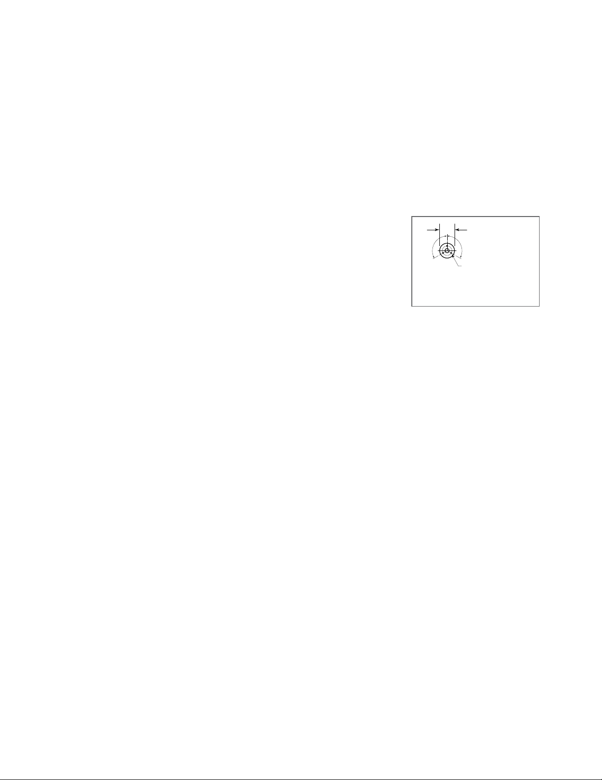
2. Once positioned
and leveled,
permanently
secure the unit's
rear flanged feet to
the floor using
5/16" lag bolts and
floor anchors
(supplied by the
installer). Three
bolts are required to secure each of the flanged
feet.
3. Seal joints of flanged feet with a silicone sealant.
GAS
ENSURE THE GAS SUPPLY MATCHES THE UNIT'S
REQUIREMENTS AS STATED ON THE RATING
PLATE.
It is recommended that a sediment trap (drip leg) be
installed in the gas supply line. If the gas pressure
exceeds 14” water column, a pressure regulator must
be installed, to provide a maximum of 14” water column
gas pressure to the gas control valve.
Connect the gas line to the manual valve located at the
rear of the control box.
Installation must be in accordance with local codes
and/or the National Fuel Gas Code ANSI Z223.1 Latest
Edition (USA) or the latest Installation Codes for Gas
Burning Appliances and Equipment CAN/ CGA B149.1
(natural gas) and CAN/ CGA B149.2 (propane gas).
Use a gas pipe joint compound which is resistant to L.P.
gas. Test all pipe joints for leaks with soap and water
solution. Ensure that the gas pressure regulator is set
for the manifold pressure indicated on the gas rating
plate.
The appliance and its individual shut-off valve must be
disconnected from the gas supply piping system during
any pressure testing of that system at test pressures in
excess of 1/2 psi (3.45 kPa). The appliance must be
isolated from the gas supply piping system by closing
its individual manual shut-off valve during any pressure
testing of the gas supply piping system at test
pressures equal to or less than 1/2 psi (3.45 kPa).
INSTALLATION
7/16"Ø, 3 HOLES
ON 3 1/8" (80mm) B.C.D.
FLANGED FOOT DETAIL
(REAR LEGS ONLY)
120 120
4 7/8" (124mm)

ELECTRICAL
NOTE: Wiring diagram is located on the underside of the
unit's control panel.
ENSURE THE ELECTRICAL SUPPLY MATCHES THE
UNIT'S REQUIREMENTS AS STATED ON THE RATING
LABEL.
A cord and plug are supplied with the 115 volt unit.
Simply plug the unit into any grounded outlet rated for a
minimum of 10 amps. The wiring diagram is located on
the back of the console access panel.
When a unit is ordered and built for 208/240 volt, the
supply line must be connected to the wiring terminations
located inside the console. A wiring diagram is attached
to the underside of the control panel.
WARNING: Electrical Grounding Instructions.
This unit is equipped with a three-prong (grounding) plug
for your protection against shock hazard and should be
plugged directly into a properly grounded three-prong
receptacle. Do not cut or remove the grounding prong
from this plug. Standard supply voltage is 115 volts A.C.,
however, optional A.C. voltages can be supplied on
special order. A separate fused disconnect switch must
be supplied and installed in the high voltage electrical
supply line. The unit when installed, must be electrically
installed and grounded in accordance with local codes,
or in the absence of local codes, with National Electrical
Code, ANSI/NFPA 70-1990 (USA) or the Canadian
Electrical Code, CSA C22.2, Part 1 (Canada).
VENTILATION
Gas fired units are only to be installed under a ventilation
hood in a room which has provisions for adequate make
up air. Further information can be obtained by referring to
the U.S.A. National Fire Protection Associations NFPA96
regulations. These standards have also been adopted by
the National Building Code in Canada.
WATER CONNECTION
(OPTIONAL)
A 1/2" NPT cold water line and/or a 1/2" NPT hot water
line are required if unit is equipped with a single or
double pantry faucet.
INSTALLATION CHECKS
Although the unit has been thoroughly tested before
leaving the factory, the installer is responsible for ensuring
the proper operation of unit once installed.
DO NOT ATTEMPT TO OPERATE THIS UNIT DURING A
POWER FAILURE.
KEEP APPLIANCE AND AREA FREE AND CLEAR OF
COMBUSTIBLES.
1. Supply power to the unit by placing the fused
disconnect switch to the "ON" position.
2. Turn on main gas supply to unit. Open the skillet's
shut-off valve (located at lower rear left).
3. Toggle HI / OFF / LO Switch to the "HI" or "LO"
position.
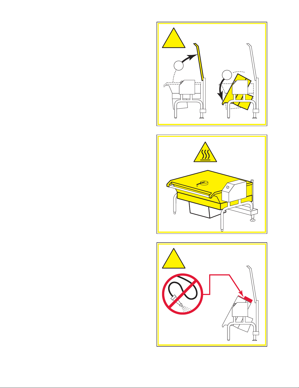
4. For your safety the skillet is equipped with a power
interrupter which automatically shuts off the gas
supply to the burners whenever the skillet is raised
more than 8°.
IMPORTANT: Before commencing to cook, ensure the
skillet pan is in the lowered position. Also ensure the
cover is raised.
5. Turn temperature control to maximum. Tilt skillet pan
until heat indicator light turns off and heating system
shuts down. The pan should be on a 5-10° angle.
6. Lower pan. Heat indicator light will re-light and
heating system will re-energize.
7. Unit will continue to heat, heat indicator light will
remain on until temperature is reached. Then the heat
indicator light will cycle OFF indicating the heating
system has shut off. The heat indicator light will
continue to cycle ON and OFF as the heating system
cycles ON and OFF maintaining the desired
temperature.
3. Toggle HI / OFF / LO Switch to the "OFF" position.
CLEANING
After installation the unit must be thoroughly cleaned and
sanitized prior to cooking.
HI
LO
OPERATING INSTRUCTIONS
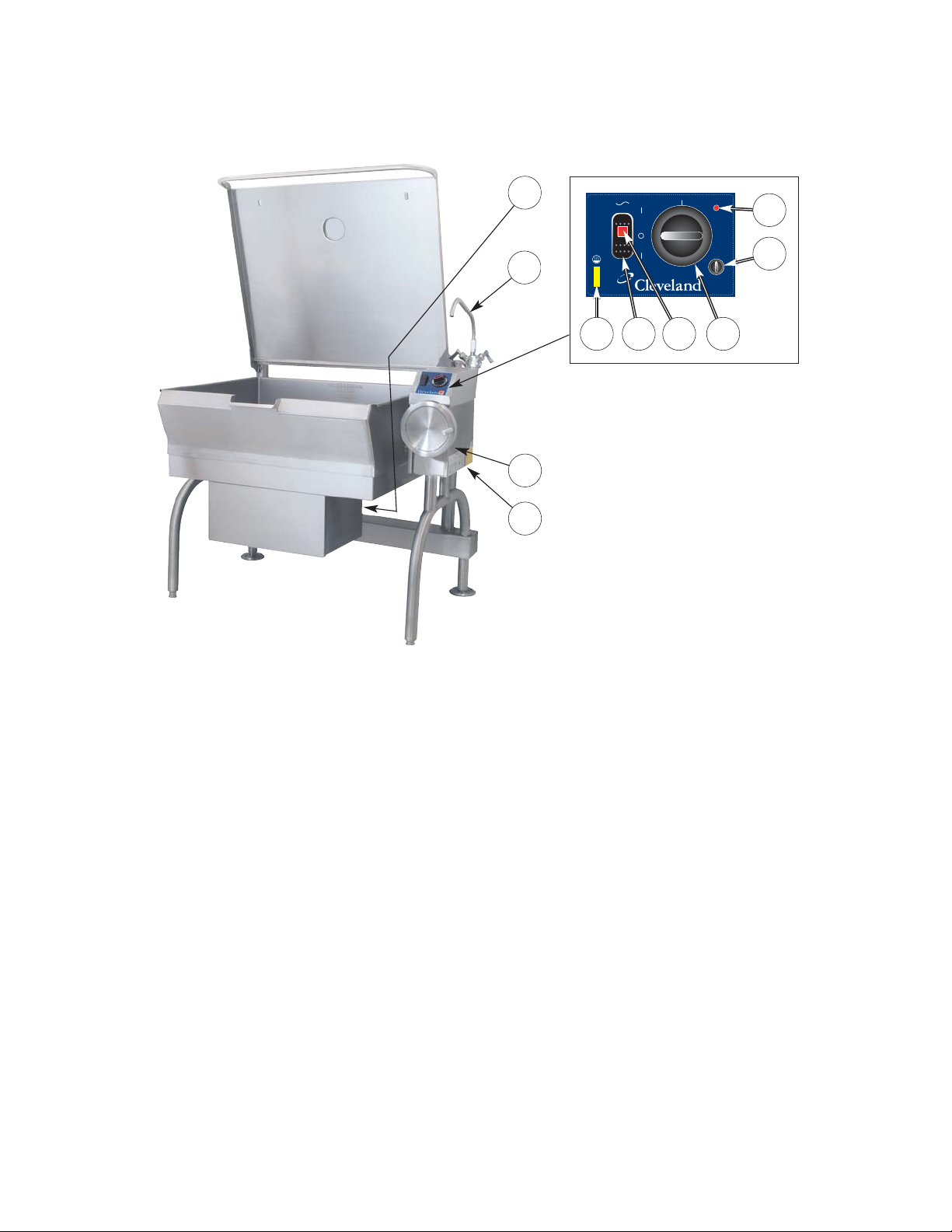
General Parts Drawing
ITEM # DESCRIPTION FUNCTION
1. HI / OFF / LO Switch Center position - power to the unit is OFF.
HI position - unit is in high fire mode (unit heats faster).
LO position - unit is in low fire mode (unit heats slower).
2. Power Indicator Light (red) Indicates power is ON.
3. Temperature Dial Regulates the surface temperature of the pan.
4. Heat Indicator Light (yellow) Turns ON when system is calling for heat and
OFF when system is satisfied.
5. Hand Tilt Wheel Used for tilting the pan up or down.
6. Power Tilt Switch Option - Used for tilting the pan up or down.
7. Reset Button Fuse protection for optional power tilt.
8. Manual Tilt Override Used on units with optional power tilt for tilting the pan up or down
in case of power or mechanical failure.
9. Gas Shut Off Valve Allows you to shut the gas off to the appliance if required.
10. Faucet Option - hot and/or cold faucet mounts to skillet for
convenient filling of the pan.
11. Tangent Draw-Off Valve Option - allows you to discharge product from the pan through
(not shown) the valve.
5
8
9
10
4 1 2 3
CONTROL PANEL
7
6
OPERATING THE UNIT
1. Ensure the gas and electrical supply to the unit are
in the ON position.
FOR YOUR SAFETY:
This skillet will automatically shut off the gas supply
when pan is raised more than 8°.
Before commencing to cook, ensure pan is in the
lowered position.
2. MANUAL TILT: Cleveland skillets are equipped
with a manual tilt mechanism for raising and
lowering the pan. To raise pan, raise the cover and
turn the crank clockwise. To lower pan, turn
counterclockwise.
POWER TILT: Cleveland skillets can also be
equipped with an optional electric power tilt
mechanism for raising and lowering the pan. To
raise pan, raise the cover and press up on the tilt
switch. To lower pan, press down on the tilt switch.
3. Toggle HI / OFF / LO Switch to the "HI" or "LO"
position. The red Power Indicator Light indicates
power is on. The yellow Heat Indicator Light
indicates burners are on.
4. To preheat, set Temperature Dial to desired
cooking temperature. Unit is preheated when the
yellow light goes out.
5. Insert product in pan.
6. If desired, once product has cooked, it can be held
prior to serving at a lower temperature setting.
7. When cooking is completed, set Temperature Dial
and HI / OFF / LO Switch to the OFF position.
8. The best time to clean the skillet is immediately
after use, once skillet has cooled down. Refer to
section titled "CLEANING INSTRUCTIONS" for
details.
OPERATING SUGGESTIONS
1. Turn power switch to the "OFF" position when skillet
is not in use.
2. Allow skillet to preheat before adding product.
3. Always lift the spring assist cover before activating
the tilt mechanism.
4. During an electrical power interruption, turn Power
Switch to the OFF position. This unit cannot be
made to operate without electrical power.
OPEN LID BEFORE
TILTING PAN
!
1
2
HOT
DO NOT
HOSE DOWN
!
THIS AREA
CARE AND CLEANING
Cooking equipment must be cleaned regularly to
maintain its fast, efficient cooking performance and
to ensure its continued safe, reliable operation. The
best time to clean is shortly after each use (allow
unit to cool to a safe temperature).
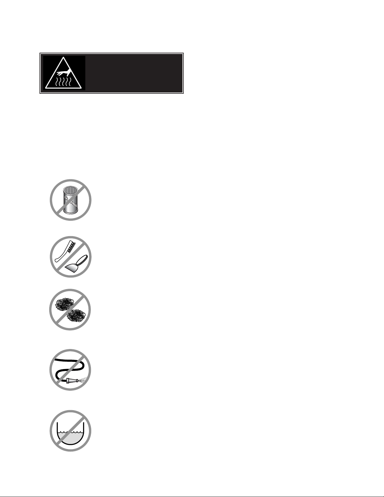
WARNINGS
➩ Do not use detergents or
cleansers that are chloride
based or contain quaternary
salt.
➩ Do not use a metal bristle
brush or scraper.
➩ Steel wool should never be
used for cleaning the stainless
steel.
➩ Unit should never be cleaned
with a high pressure spray
hose.
➩
Do not leave water sitting in unit
when not in use.
Stagnant
Water
High Pressure
Spray Hose
Chloride Cleaners
Steel Pads
Wire Brush &
CLEANING INSTRUCTIONS
CAUTION
SURFACES MAY
BE EXTREMELY HOT!
CLEANING INSTRUCTIONS
1. Turn unit off.
2. Remove drain screen (if applicable). Thoroughly
wash and rinse the screen either in a sink or a
dishwasher.
3. Prepare a warm water and mild detergent solution in
the unit.
4. Remove food soil using a nylon brush.
5. Loosen food which is stuck by allowing it to soak at
a low temperature setting.
6. Drain unit.
7. Rinse interior thoroughly.
8. If the unit is equipped with a Tangent Draw-Off
Valve, clean as follows:
a) Disassemble the draw-off valve first by turning
the valve knob counter-clockwise, then turning
the large hex nut counter-clockwise until the
valve stem is free of the valve body.
b) In a sink, wash and rinse the inside of the valve
body using a nylon brush.
c)
Use a nylon brush to clean tangent draw-off tube.
d) Rinse with fresh water.
e) Reassemble the draw-off valve by reversing the
procedure for disassembly. The valve's hex nut
should be hand tight only.
9. If the unit is equipped with a Butterfly Valve, clean
as follows:
a) Place valve in open position.
b) Wash using a warm water and mild detergent
solution.
c) Remove food deposits using a nylon brush.
d) Rinse with fresh water.
e) Leave valve open when unit is not in use.
10 . Using mild soapy water and a damp sponge, wash
the exterior, rinse, and dry.
NOTES
➩ For more difficult cleaning applications one of the
following can be used: alcohol, baking soda, vinegar,
or a solution of ammonia in water.
➩ Leave the cover off when the kettle is not in use.
➩ For more detailed instructions refer to the Nafem
Stainless Steel Equipment Care and Cleaning manual
(supplied with unit).

STAINLESS STEEL EQUIPMENT CARE AND CLEANING
(Suppied courtesy of Nafem. For more information visit their web site at www.nafem.org)
Contrary to popular belief, stainless steels ARE susceptible to rusting.
Corrosion on metals is everywhere. It is recognized quickly on iron and
steel as unsightly yellow/orange rust. Such metals are called “active”
because they actively corrode in a natural environment when their atoms
combine with oxygen to form rust.
Stainless steels are passive metals because they contain other metals, like
chromium, nickel and manganese that stabilize the atoms. 400 series
stainless steels are called ferritic, contain chromium, and are magnetic;
300 series stainless steels are called austenitic, contain chromium and
nickel; and 200 series stainless, also austenitic, contains manganese,
nitrogen and carbon. Austenitic types of stainless are not magnetic, and
generally provide greater resistance to corrosion than ferritic types.
With 12-30 percent chromium, an invisible passive film covers the steel’s
surface acting as a shield against corrosion. As long as the film is intact
and not broken or contaminated, the metal is passive and stain-less. If the
passive film of stainless steel has been broken, equipment starts to
corrode. At its end, it rusts.
Enemies of Stainless Steel
There are three basic things which can break down stainless steel’s
passivity layer and allow corrosion to occur.
1. Mechanical abrasion
2. Deposits and water
3. Chlorides
Mechanical abrasion means those things that will scratch a steel surface.
Steel pads, wire brushes and scrapers are prime examples.
Water comes out of the faucet in varying degrees of hardness. Depending
on what part of the country you live in, you may have hard or soft water.
Hard water may leave spots, and when heated leave deposits behind that
if left to sit, will break down the passive layer and rust stainless steel. Other
deposits from food preparation and service must be properly removed.
Chlorides are found nearly everywhere. They are in water, food and table
salt. One of the worst chloride perpetrators can come from household and
industrial cleaners.
So what does all this mean? Don’t Despair!
Here are a few steps that can help prevent stainless steel rust.
1.
Use the proper tools.
When cleaning stainless steel products, use non-abrasive tools. Soft
cloths and plastic scouring pads will not harm steel’s passive layer.
Stainless steel pads also can be used but the scrubbing motion must
be in the direction of the manufacturers’ polishing marks.
2.
Clean with the polish lines.
Some stainless steel comes with visible polishing lines or “grain.”
When visible lines are present, always scrub in a motion parallel to the
lines. When the grain cannot be seen, play it safe and use a soft cloth
or plastic scouring pad.
3.
Use alkaline, alkaline chlorinated or non-chloride containing cleaners.
While many traditional cleaners are loaded with chlorides, the industry
is providing an ever-increasing choice of non-chloride cleaners. If you
are not sure of chloride content in the cleaner used, contact your cleaner
supplier. If your present cleaner contains chlorides, ask your supplier if
they have an alternative. Avoid cleaners containing quaternary salts; it
also can attack stainless steel and cause pitting and rusting.
4.
Treat your water.
Though this is not always practical, softening hard water can do much
to reduce deposits. There are certain filters that can be installed to
remove distasteful and corrosive elements. To insure proper water
treatment, call a treatment specialist.
5.
Keep your food equipment clean.
Use alkaline, alkaline chlorinated or non-chloride cleaners at
recommended strength. Clean frequently to avoid build-up of hard,
stubborn stains. If you boil water in stainless steel equipment,
remember the single most likely cause of damage is chlorides in the
water. Heating cleaners that contain chlorides have a similar effect.
6.
Rinse, rinse, rinse.
If chlorinated cleaners are used, rinse and wipe equipment and
supplies dry immediately. The sooner you wipe off standing water,
especially when it contains cleaning agents, the better. After wiping
equipment down, allow it to air dry; oxygen helps maintain the
stainless steel’s passivity film.
7.
Never use hydrochloric acid (muriatic acid) on stainless steel.
8.
Regularly restore/passivate stainless steel.
Recommended cleaners for specific situations
Job Cleaning Agent Comments
Routine cleaning Soap, ammonia, Apply with cloth or sponge
detergent, Medallion
Fingerprints & smears Arcal 20, Lac-O-Nu Provides barrier film
Ecoshine
Stubborn stains & Cameo, Talc, Zud, Rub in direction of polish lines
discoloration First Impression
Grease & fatty acids, Easy-off, De-Grease Excellent removal on all finishes
blood, burnt-on-foods It Oven Aid
Grease & oil Any good Apply with sponge or cloth
commercial detergent
Restoration/Passivation Benefit, Super Sheen
Review
1. Stainless steels rust when passivity (film-shield) breaks down as a
result of scrapes, scratches, deposits and chlorides.
2. Stainless steel rust starts with pits and cracks.
3. Use the proper tools. Do not use steel pads, wire brushes or scrapers
to clean stainless steel.
4. Use non-chlorinated cleaners at recommended concentrations. Use
only chloride- free cleaners.
5. Soften your water. Use filters and softeners whenever possible.
6. Wipe off cleaning agent(s) and standing water as soon as possible.
Prolonged contact causes eventual problems.
To learn more about chloride-stress corrosion and how to prevent it,
contact the equipment manufacturer or cleaning materials supplier.
Developed by Packer Engineering, Naperville, Ill., an independent testing
laboratory.
 Loading...