

Page 1
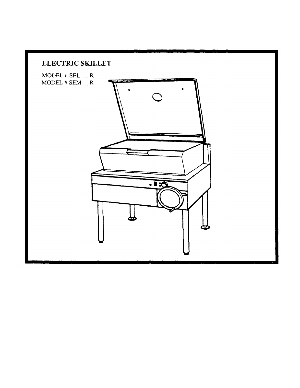
INSTALLATION, OPERATION AND REPAIR MANUAL
CLEVELAND RANGE COMPANY
1177 Kamato Rd.
Mississauga, Ontario
L4W 1X4
Telephone: (905) 624-0260 Toll Free
Fax: 1-800-316-7745
P115-(Rev. 10/93)
CLEVELAND RANGE COMPANY
1333 East 179th St.
Cleveland, Ohio
U.S.A. 44110
Telephone: (216) 481-4900 FAX:
(216) 481-3782
SKI-08
Page 2

INSTALLATION INSTRUCTIONS GENERAL INFORMATION
WARNING: Installation of skillet must be accomplished by qualified installation personnel, working to
all applicable local and national codes. Improper
installation of product could cause injury or damage.
The serial plate is located on the frame softener (right
side) behind the front panel. For easy access, remove
the two screws securing the upper front panel and
hinge the lower front panel downwards. Voltage,
phase, amperage and wattage are stated on the plate.
This equipment is built to comply with applicable
standards for manufacturers. Included among those
approval agencies are: CSA, NRTL/C,NSF and others.
Many local codes exist, and it is the responsibility of
the owner and installer to comply with these codes.
1. Damage Check: Check carton or crate for possible
damage incurred in shipping. After carefully
uncrating, check for 'concealed' damage. Report
any damage immediately to your carrier.
2. Check the electrical rating plate to ensure that the
INSPECTION
unit is the correct voltage, amperage, phase and
wattage.
Before unpacking, visually inspect the unit for evidence of damage during shipping. If damage is
noticed, do not unpack the unit, follow shipping
damage instructions.
SHIPPING DAMAGE INSTRUCTIONS
If shipping damage to the unit is discovered or
suspected, observe the following guidelines in preparing a shipping damage claim.
1. Write down a description of the damage or the.
reason for suspecting damage as soon as it is
discovered. This will help in filling out the claim
forms later.
2. As soon as damage is discovered or suspected, notify
the carrier that delivered the shipment.
3. Arrange for the carrier's representative to examine
damage.
4. Fill out all carrier claims forms and have the
examining carrier sign and date each form.
3. This unit must be installed by a qualified electrician working in accordance with applicable
local and national electrical codes. Improper
installation could cause damage and void the
warranty.
INSTALLATION CLEARANCES
This unit must be installed in accordance with the
following clearances in order to provide propel
operation and servicing of the appliance. Also, it is
recommended that the unit be installed with suf ficient
clearances to provide proper cleaning and
maintenance. Minimum clearances are 0" for the sides
and back.
INSTALLATION INSTRUCTIONS
1. Carefully remove unit from carton or crate. Remove
any packing material from unit.
2. A protective material has been applied to the
stainless steel panels.
-2-
Page 3

NOTE: This material must be removed immediately after installation, as heat will melt the
material and make it more difficult to remove.
3. Set skillet in position where electrical services are
nearby. Comply with clearances stated on the
specification sheet. Ensure there is sufficient
clearance between skillet and back wall. Check
overhead clearance to accommodate hinged cover
when in the raised position.
OPERATTNG INSTRUCTIONS
1. Ensure electrical supply to the appliance is in the
'ON' position.
2. Turn power switch to the 'ON' position. The green
pilot light will indicate power is on.
3. Power Tilt
4. Level skillet by means of adjustable stainless steel
feet. Use a spirit level and level unit four ways:
across front and back and down left and right
edges. Securely anchor adjustable feet to floor and
seal joints with a silicone sealant.
ELECTRICAL CONNECTION
1. For supply connections, use wire suitable for at
least 194°F (90°C). Cleveland strongly recommends the use of liquid tight fittings.
2. The supply lines will enter through the rear (or
bottom) of the unit near the left side of the skillet
and are connected to the terminal block. For ease
in attaching the supply lines, there is a remova ble
cover on the wiring compartment.
3. The electrical service connection must comply
with all local and national codes.
4. NOTE: This skillet is factory wired for a 3 phase
installation. If single phase is required. check the
wiring diagram for proper modifications. Wiring
diagram is located on the back of the hinged front
panel.
WATER CONNECTIONS (OPTIONAL)
A 3/8" NPT cold water line and a 3/8" NPT hot water
line are required for the fill faucet.
Cleveland skillets are equipped with an electric
power tilt mechanism for raising and low ering the
frypan. To raise the frypan. open the cover and
press up on the tilt switch. To lower the frypan.
press down on the tilt switch.
Manual Tilt
Cleveland skillets can also be equipped with the
optional manual tilt mechanism for raising and
lowering the frypan. To rais e the frypan. open the
cover and mm the wheel clockwise. To lower the
frypan, push in on the lever lo cated behind the
wheel.
4. FOR YOUR SAFETY: This skillet is also equipped
with a power interrupter which automatically
shuts off the electrical power to the elements
whenever the frypan is raised more than 1/2"
(13mm).
IMPORTANT: Before commencing to cook,
ensure frypan is in the lowered position by
pressing down on the tilt switch. Ensure cover is
raised first.
5. To preheat, set thermostat to desired cooking
temperature. The amber pilot light will cycle on
and off with the thermostat.
6. Allow skillet to preheat for approximately 15-30
minutes.
7. Once preheated, insert product in frypan and
-3-
Page 4

adjust thermostat to required cooking temperature.
8. If desired, once product has cooked, it can be held
prior to serving at a lower temperature setting.
9. The best time to clean the skillet is immediately
after use, once frypan has cooled down. Refer to
the section titled CLEANING INSTRUCTIONS.
OPERATING SUGGESTIONS
1. Turn power switch to the 'OFF' position when
skillet is not in use.
2. Clean frypan as soon as possible after cooking.
service agency arc recommended to check temperatures, adjustments and ensure moving parts are
operative. Whenever possible, avoid overheating idle
equipment as this is the primary cause for increased
service costs.
When corresponding with the factory or your
equipment dealer regarding service problems or
replacement parts, be sure to refer to the particular unit
by the correct model number (including prefix and
suffix letters and numbers) and the serial or code
number. The rating plate affixed to the unit contains
this information.
"REGULAR MAINTENANCE ENSURES PEAK
PERFORMANCE".
3. Allow skillet to preheat before adding product
4. Always lift the spring assist cover before activating the tilt mechanism.
5. During an electrical power interruption, turn power
switch on the front panel, to the 'OFF' position.
This unit cannot be made to operate without
electrical power.
MAINTENANCE INSTRUCTIONS
NOTE: ANY MAINTENANCE OR SERVICE
INVOLVING DISSASSEMBLY OF COMPONENTS
SHOULD BE MADE BY A QUALIFIED SERVICE
TECHNICIAN. ENSURE ELECTRICAL AND
WATER SUPPLY (IF APPLICABLE) TO THE
APPLIANCE ARE SHUT OFF.
You have purchased the finest commercial cooking
equipment available anywhere. Like any other fine
precision built piece of equipment it should be given
regular care and maintenance.
Periodic inspections by your dealer or a qualified
CLEANING INSTRUCTIONS
A regular daily cleaning program should be followed to
maintain your skillet's efficient perfor mance and
minimize service calls. At the end of each day's
operation, the following steps are recommended:
1. Turn pow er switch to the 'OFF' position.
2. Skillet should be cleaned after each use, as soon as
possible after cooking.
CAUTION: Ensure skillet has cooled down.
3. For general purpose cleaning, use a soft cloth with
mild detergent and warm water. A sponge, nonabrasive scouring pad or a fibre brush can also be
used for this purpose.
4. To remove grease that has baked on, apply a nonabrasive cleanser to a damp cloth or sponge and rub
cleanser on the metal in the direction of the
polishing lines of the metal. NEVER RUB IN A
CIRCULAR MOTION. Soil or burnt deposits
which do not respond can usually be removed by
rubbing the surface with Scotch-Brite scouring
pads or stainless scouring pads. DO NOT USE
ORDINARY STEEL WOOL.
-4-
Page 5

5. Do not use grill stones. Heat tint can be removed
by a vigorous scouring in the direction of the
polish lines using Scotch-Brite scouring pads or a
stainless scouring pad in combina tion with a nonabrasive cleanser.
6. Tomato and vinegar based products have a high
acid content which could attack the stainless
steel finish of the frypan. After cooking of such
products, clean frypan interior with a baking soda
and water solution. Use one tablespoon of baking
soda per one gallon of water.
7. After cleaning, the skillet should be thoroughly
rinsed with clean water and dried.
-5-
Page 6
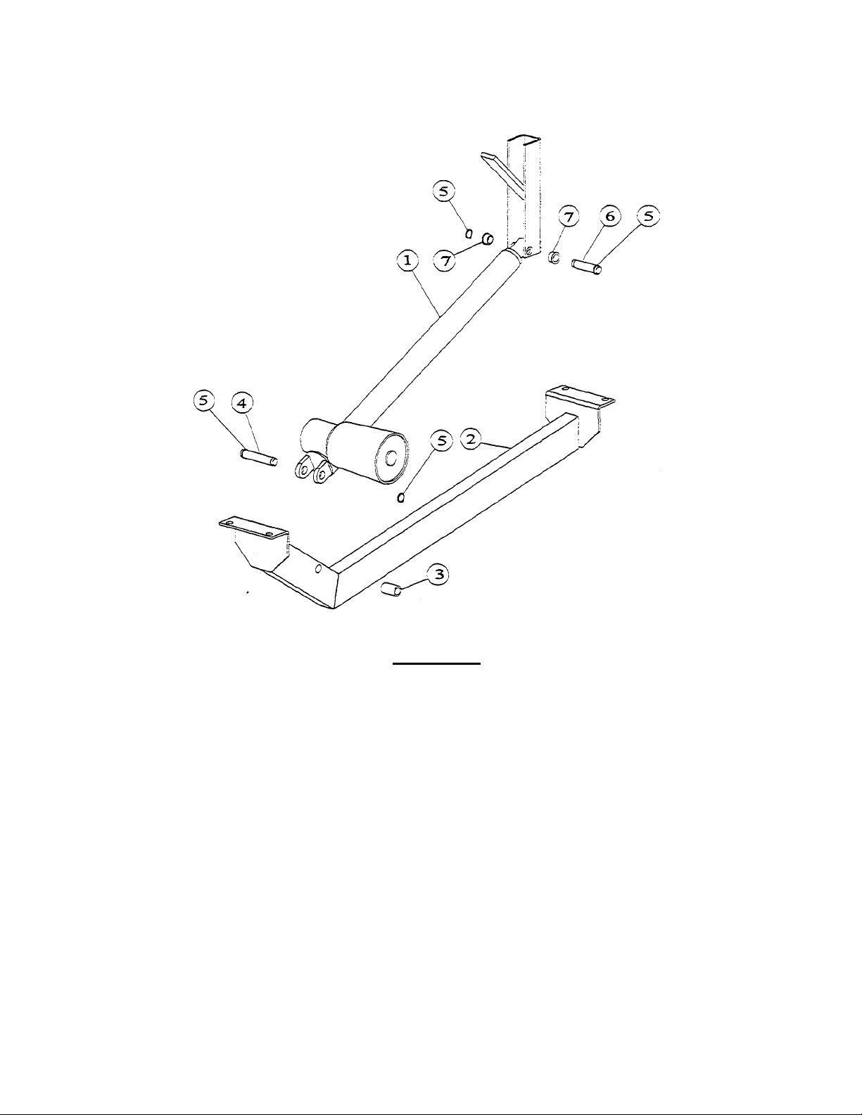
ACTUATOR
Item Part No. Description Qty.
1 2346100 Actuator 1
2 2337499 Actuator Mounting Bracket Assy 1
3 2357500 Sleeve Bearing 1
4 2376500 Actuator Pin (Front) 1
5 2376502 Retaining Ring 4
6 2376501 Actuator Pin (Rear) 1
7 2357400 Flange Bearing 2
Page 7
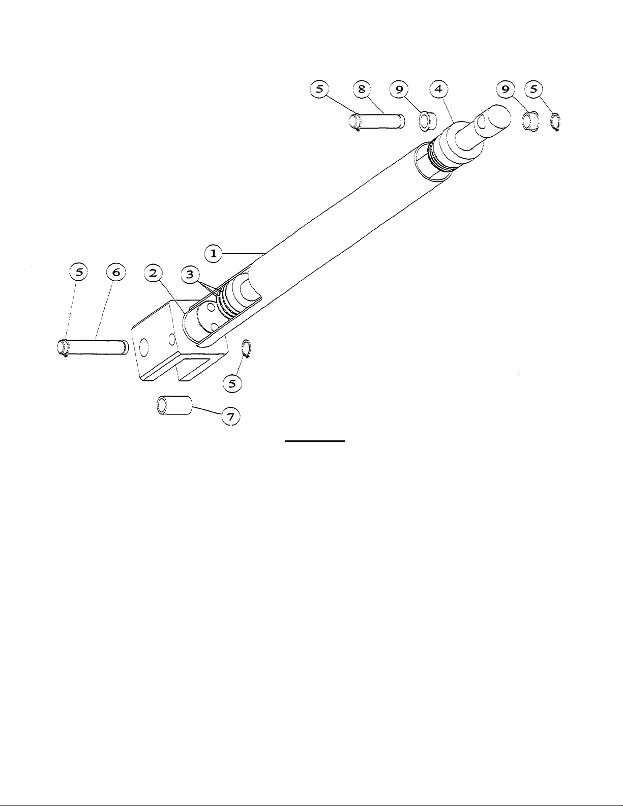
HAND TILT
Item Part No. Description Qty.
*1 2381000 Hydraulic Cylinder 1
*2 2388400 "0" Ring 1
*3 2388300 "U" Cup 3
*4 2388500 Top Bearing 1
5 2376502 Retaining Ring 4
6 2376500 Actuator Pin (Front) 1
7 2357500 Sleeve Bearing 1
8 2376501 Actuator Pin (Rear) 1
9 2357400 Flange Bearing 2
• - Part No.'s 1, 2, 3, 4 purhased as assembly 2381000
-7-
Page 8

PAN HINGE
Item Part No. Description Qty.
1 F424 Lock Nut 1/2-13 S.S. 2
2 F257 Lock Washer 1/2-13 S.S. 2
3 078248-1 Spacer 2
4 G02925-2 Bushing 2
5 F59 Bolt 1/2-13x3/4" 2
6 F183 Truss Head Screw 8-32 x 1 S.S. 1
7 F237 Hex Nut 8-32 S.S. 1
8 2354199 Striker Plate Assy 1
9 F359 Set Screw 1/2-13x1-3/4 1
10 F358 Hex Jam Nut 1/2-13 1
11 F246 Hex Nut 1/2-13 S.S.
-8-
Page 9

PLATE
Item Part No. Description Qty.
1 2300600 Hi-Limit 1
2 2353900 Bulb Clamp 1
3 2354099 Bulb Shield Assy 1
4 F95 Nut 1
5 2345100 RTD Sensor 1
6 2344900 Shield Liner 1
7 2345000 Shield 1
-9-
Page 10

-10-
Page 11

HYDRAULIC TILT ASSEMBLY
Item Part No. Description Qty.
1 2379100 Hydraulic Adaptor 2
2 2379600 Hydraulic Hose Assy 1
3
4 2379500 Hydraulic Hose Assy 1
5 2379000 Hydraulic A daptor 1
6 2379001 Hydraulic Adaptor 1
7 2378901 Tee F/M/M 1
8 2379400 Check Valve 1
9 2379300 Ball Valve c/w Handle and Nut 1
10 2382700 Valve Return Spring 1
11 2378900 TeeM/F/M 1
12 2375699 Oil Tank Assy 1
13 2250700 Plug (Drilled) 1
14 2376200 Link Rod 1
15 078279-1 Ball Knob 1
16 F430 Hitch Pin 1
17 2379201 "0" Ring Boss 90° 1
18 2379203 "0" Ring .644" 1
19 2379200 "0" Ring Boss 1
20 2379202 "0" Ring .468" 1
21 2378800 Hydraulic Pump 1
22 078072-6P Handwheel 1
23 078108-1 P Revolving Handle 1
24 F212 Hex Screw 1
25 02973-4 Heyco Plug 1
2379501
Hydraulic Hose Assy 30 Gal.
-11-
1
Page 12

-12-
Page 13

CONTROL PANEL
Item Part No. Description Qty.
1 2343500 Power Switch 1
2 2343501 Tilt Switch (Power Tilt Only) 1
3 2138700 Dial 1
4
5 23480 Graphic Overlay (Specify Model) 1
6 23561 Indicator Light - Green (Specify Voltage) 1
7 2356102 Indicator Light - Amber 1
8 2142002 Electronic Thermostat 1
9
10 F419 Sealer Washer 4
11 2147403 Liquid-Tight Fitting 5/8" 1
12 2147402 Liquid-Tight Fitting 3/8" 1
13 2147401 Liquid-Tight Fitting 5/16" (Power Tilt Only) 1
14 2147400 Liquid-Tight Fitting 3/16" 1
15
16 2353100 Control Box Cover 1
17 2383200 Control Cover Gasket 1
18 2357900 Neoprene Gasket 1
19 2300600 High Limit 1
-13-
2360701
050069
2352899
Control Box Assy - Power Tilt
Dial Insert °C
Terminal Block
8
1
1
Page 14

-14-
Page 15

ELECTRICAL BOX
Item Parts No. Description Qty.
1 077190-2
077190-4
077190-5
077190-6
2 1427305 Capacitor (Power Tilt Only) 1
3 2282100 Capacitor Clamp (Power Tilt Only) 1
4 1426600 Resistor (Power Tilt Only) 1
5 077145-2 Rectifier (Power Tilt Only) 1
6 2320702 Fuse Holder 1
7 2346303
2346304
8 2346306 Fuse 1A AGC (Power & Hand Tilt) 1
9 2346302 Fuse 15A MDA (Power Tilt Only) 1
Transformer-Power Tilt 208/240/480V
Transformer-Power Tilt 220/380V
Transformer-Hand Tilt 208/240/480V
Transformer-Hand Tilt 220/380V
Fuse 1.5A MDL -Power Tilt 208/220/240V
Fuse 0.5A AGC-Hand Tilt 208/220/240V
1
1
1
1
1
1
10 2147403 Liquid-Tight Fitting 5/8" 1
11 G01268-1
G01268-2
G01280-4-7
G01280-3-7
12 2147401 Liquid-Tight Fitting 5/16" 1
13 2348100 Sealed Switch 1
14 1489700
1489800
15 050069 Terminal Block - Junction
16 050070 Terminal End 1
Terminal Block - 220/240V Export
Terminal Block - 380/415/480V Export
Terminal Block - All Domestic Models
Terminal End
Terminal Channel - 4 Blocks
Terminal Channel - 3 Blocks
Contactor 3 Pole - 208/240V Domestic
Contactor 3 Pole - 220/240V Export
Contactor 4 Pole - 380/415/480V
Terminal Block - Line
1
2
1
1
8
2
17 2274600 1/2" Liquid-Tight Connector Straight 3
-15-
Page 16

-16-
Page 17

PAN
Item Part No. Description Qty.
1 2356300
2373000
2356302
2373002
2356305
2373005
2356200
2372400
2356202
2372902
2356205
2372905
2 2364101
2364100
2360301
2360300
3 2364201
2364200
2360401
2360400
Element - Centre 4.8kw 208V 30 Gal.
Element - Side 4.8kw 208V 30 Gal.
Element - Centre 4.8kw 240V 30 Gal.
Element - Side 4.8kw 240V 30 Gal.
Element - Centre 4.8kw 480V 30 Gal.
Element - Side 4.8kw 480V 30 Gal.
Element - Centre 6.0kw 208V 40 Gal.
Element - Side 6.0kw 208V 40 Gal.
Element - Centre 6.0kw 240V 40 Gal.
Element - Side 6.0kw 240V 40 Gal.
Element - Centre 6.0kw 480V 40 Gal.
Element - Side 6.0kw 480V 40 Gal.
Element Clamp - Centre 30 Gal.
Element Clamp - Side 30 Gal.
Element Clamp - Centre 40 Gal.
Element Clamp - Side 40 Gal.
Element Cover - Centre 30 Gal.
Element Cover - Side 30 Gal.
Element Cover - Centre 40 Gal.
Element Cover - Side 40 Gal.
1
2
1
2
1
2
1
2
1
2
1
2
1
2
1
2
1
2
1
2
4 2382000
2381200
5 2381900
2381300
6 2382200
2381500
7 2382100
2381400
8 2364700 Bulb Shield 1
9 2372200 Enclosure Cover 1
10 2364300 Element Terminal Box 3
11 2364400 Terminal Box Cover 3
12 2274800 1/2" Liquid-Tight Connector 45° 2
13 2274600 1/2" Liquid-Tight Connector Straight 1
Heat Baffle - Outer 30 Gal.
Heat Baffle - Outer 40 Gal.
Heat Baffle - inner 30 Gal.
Heat Baffle - Inner 40 Gal.
Heat Baffle - Centre Rear 30 Gal.
Heat Baffle - Centre Rear 40 Gal.
Heat Baffle - Centre Front 30 Gal.
Heat Baffle - Centre Front 40 Gal.
2
2
2
1
1
2
2
1
-17-
Page 18

SPRING ASSY
Item Part No. Description Qty.
1 2360600 Spring 2
2 2381700 Turnbuckle Body 2
3 2374900
2374901
4 2372799
2372798
5 F299 Bolt 1/4-20 x 1/2" Shoulder 2
6 F112 Flat Washer 3/8" l.D. 4
7 F255 Lock Washer 1/4" l.D. 2
8 F239 Nut 1/4-20 S.S. 2
9 2372400 Bell Crank Hook 2
-18-
Connecting Rod R/H Thread
Connecting Rod L/H Thread
Bell Crank Assy R/H
Bell Crank Assy L/H
1
1
1
1
Page 19

SHAFT ASSY
Item Part No. Description Qty.
1 2142002 Electronic Thermostat 1
2 2159300 Insulator - Thermostat 1
3 2167000 Spring Tension Pin 1
4 2166800 Potentiometer Shaft 1
5 2167200 Retaining Ring 1
6 2167100 Bowed Spring Washer 1
7 2167300 Panel Bearing Assy 1
8 2382800 Retaining Spring 1
9 2166900 Stop Plate 1
10 2358600 Stop Plate Spacer 1
11 2358200 Rotary Shaft Seal 1
12 F419 Sealer Washer 2
13 F163 Screw 6-32 x 3/8 2
-19-
Page 20

DWG:2375301 -20-
Page 21

K.W.
LOADING PER LINE
NOMINAL AMPS PER LINE
TOTAL K.W.
LOADING
1 PHASE.
5 PH 3 PH
1 MODEL
SEL40
18,0 6 6 8
81.8 75.0 1
27.3 25.0
57
55 54
51 18 TEW X BLACK
4 1
1/4
FAST ON
-
1/4 FAST ON
50 18
TEW X BLACK
4 1
1/4
FAST ON
-
1/4 FAST ON
49 18
TEW X BLUE
11 1 #1 RING
-
1/4 FAST O
N 48 18 TEW X ORANGE
9 1
1/4
FAST ON
-
3/8 STRIP
46 18 TEW X BLACK
9 1
1/4
FAST ON
-
3/8 STRIP
42 18 TEW X WHITE
9 1
1/4
FAST ON
-
.3/8 STRIP
41 18
TEW X RED 9 1 1/4
FAST ON
-
3/8 STRIP
40 16
TEW X RED 8 1 3/8
STRIP
-
3/8 STRIP
39 16
TEW X RED 8 1 3/8
STRIP
-
1/4 FAST ON
37 16 TEW X BLACK
8 1
3/8
STRIP
-
1/4 FAST ON
36 16
TEW X BLACK
27 1
1/4
FAST ON
-
1/4 FAST ON
34 16 TEW X BLACK
23 1
1/4
FAST ON
-
#8 RING
33 18
TEW X RED 32 1 1/4
FAST ON
-
#10 RING
31
8 7
A.V
USE FROM SERIAL No.
______
TO
______
L1 L2 L3 208 220 240 208 240 380 415 480 220/38
240/41
F40E 18.0 6 6 6 81.8 75.0 27.3 25.0
, F30E 14.4 4.8 4.8 4.8 65.5 80.0 21.8 20.0
SEL30 14.4 4,8 4.8 4.8 85.5 60.0 21.8 20.0
58
56
Cable 2
Cable 1I 16
18 SVT X 29
S090' X 45.5
47 18 TEW X BLUE 11 1 # RING -3/8 STRIP
45 16 TEW X RED 9 1 1/4 FAST ON-3/8 STRIP
44 16 TEW X BLACK 9 1 1/4 FAST ON-3/8 STRIP
43 18 TEW X RED 9 1 1/4 FAST ON-3/8 STRIP
38 16 TEW X BLACK 8 1 1/4 FAST 0N-#8 RING
29
28 18 TEW X ORANG
27 18 SO X BLACK TILT SW
26 18 TEW X BLACK 25
25 16 TEW X RED 24
24 16 TEW X BLACK 24
23 16 TEW X RED 26
22 18 TEW X WHITE 22
21 16 TEW X RED 21 1 3/8 STRIP-1/4 FAST ON
20 16 TEW X GREEN 20 1 #10 RING-#10 RING
19
18
17
16 10 CL125
15 10 SEW-1 X BLACK 94 1 1/2 STRIP-#10 Ring
14 10 SEW-1 X RED 79 1 #10 RING-#10 RING
13 10 SEW-1 X BLACK 85 1 1/2 STRIP-#10 RING
12 10 SEW- X RED 70 1 #10 RING-#10 RING
11 10 SEW-1 X BLACK 78 1 1/2 STRIP-#10 0 RING
10 10 SEW-1 X RED 63 1 #10 RING-#10 RING
9
X GREEN 10 1
33 1 3/8 STRIP-1/4 FAST ON
1/4 INTERRUPT LEAD
3/8 STRIP-1/4 FAST ON
3/8 STRIP-3/8 STRIP
3/8 STRIP-3/8 STRIP
3/8 STRIP-#8 RING
3/8 STRIP-#8 RING
#10 RING-#10 RING
35 18 TEW X BLACK 23 1 1/4 FAST ON-#8 RING
32 16 TEW X BLACK 29 1 #8 RING -1/2 STRIP
30 18 TEW X WHITE 17 1 1/4 STRIP- #8 RING
No. GA. Type SOLID
DESCRIPTION DR. DATE REV. #
REVISIONS
6
5
4
3 10 SEW-1 X RED 22 1 1/2 STRIP-#10 RING
2 10 SEW-1 X RED 22 1 1/2 STRIP- #10 RING
Strand
COLOR LENGTH
QTY
CONNECTIONS
1 10 SEW-1 X RED 22 1 1/2 STRIP-#10 RING
NO GA. TYPE SOLID
COLOR TG3/TG4
QTY CONNECTIONS
220/240V 3N~
1 MODEL
No.
2375301/
DATE! OCT.
1/93
OR;
Page 22

-22-
Page 23

K.W. LOADING PER LINE
NOMINAL AMPS PER LINE
TOTAL K.W.
1 PHASE
3 PH 3 PH
MODEL
1
1
1
1
1
8
5 4
STRAND
A.V.
USE FROM SERIAL No.
______
TO
______
LOADING
LI L2 L3 208 220 | 240 208 240 380 415 480 220/380 240/415
F40E 10.0 6 6 6 81.8 75.0 | 27.3 25.0
F30E 14.4 4.8 4.8 4.8 65.5 60.0 21.8 20.0
SEL40 18.0 6 6 6 81.8 75.0 27.3 25.0
SEL30 14.4
4.8 4.8 4.8
65.5 60.0
21.8 20.0
58
57
56
55
54
cable 16 S090-C X
51
50
49 18 TEW X BLUE 11 1 #10 RING-1/4 FAST ON
48 18 TEW X ORANGE 9 1 1/4 FAST ON-3/8 STRIP
47 18 TEW X BLUE 11 1 #10 RING-3/8 STRIP
46 18 TEW X BLACK 9 1 1/4 FAST ON-3/8 STRIP
45 16 TEW X RED 9 1 1/4 FAST ON-3/8 STRIP
44 16 TEW X BLACK 9 1 1/4 FAST ON-3/8 STRIP
43 18 TEW X RED 9 1 1/4 FAST ON-3/8 STRIP
42 18 TEW X WHITE 9 1 1/4 FAST ON-3/8 STRIP
41 18 TEW X RED 9 1 1/4 FAST ON-3/8 STRIP
40
39
38
37
36
35 18 TEW X BLACK 23 1 1/4 FAST ON-#8 RING
34
33 18 TEW X RED 32 1 1/4 FAST ON-#10 RING
32 18 TEW X BLACK 29 1 #8 RING-1/2 STRIP
31
30 18 TEW X WHITE 17 1 1/4 STRIP-#8 RING
No. GA. TYPE SOLID
COLOR L.ENGTH QTY CONNECTIONS
STRAND
45.5
28 18 TEW X ORANGE 33 1 3/8 STRIP-1/4 FAST ON
27 18 SO X BLACK TILTSW 1 1/4 INTERRUPT LEAD
26 18 TEW X BLACK 25 1 3/8 STRIP-1/4 FAST ON
25
24
23 16 TEW X RED 26 1 3/8 STRIP-#8 RING
22 18 TEW X WHITE 22 1 3/8 STRIP-#8 RING
21 16 TEW X RED 21 1 3/8 STRIP-1/4 FAST ON
20 16 TEW X GREEN 20 1 #10 RING-#10 RING
19
18
17
16 10 CL1251 X GREEN 10 1 #10 RING-#10 RING
15 10 SEW-1 X BLACK 94
14 10 SEW-1 X RED 79
13 10 SEW-1 X BLACK 85
12 10 SEW-1 X RED 70
11 10 SEW- 1 X BLACK 78
10 10 SEW-1 X RED 63
9
7
6
3 10 SEW--1 X RED 22 1 1/2 STRIP-#10 RING
2 10 SEW-1 X RED 22 1 1/2 STRIP-#10 RING
1 10 SEW-1 X RED 22 1 1/2 STRIP -#10 RING
No. GA.
TYPE SOLID
COLOR TG3/TG4
MODEL No.:
F30,40E-L,MHTR
SEL,M-30.40HTR
LENGTH
1/2 STRIP-#10 RING
#10 RING-#10 RING
1/2 STRIP-#10 RING
#10 RING-#10 RING
1/2 STRIP-#10 RING
1
#10 RING-#10 RING
QTY CONNECTIONS
DATE:
OCT.1/93
2375302
DR:
29
220/240V 3N~
 Loading...