

Page 1
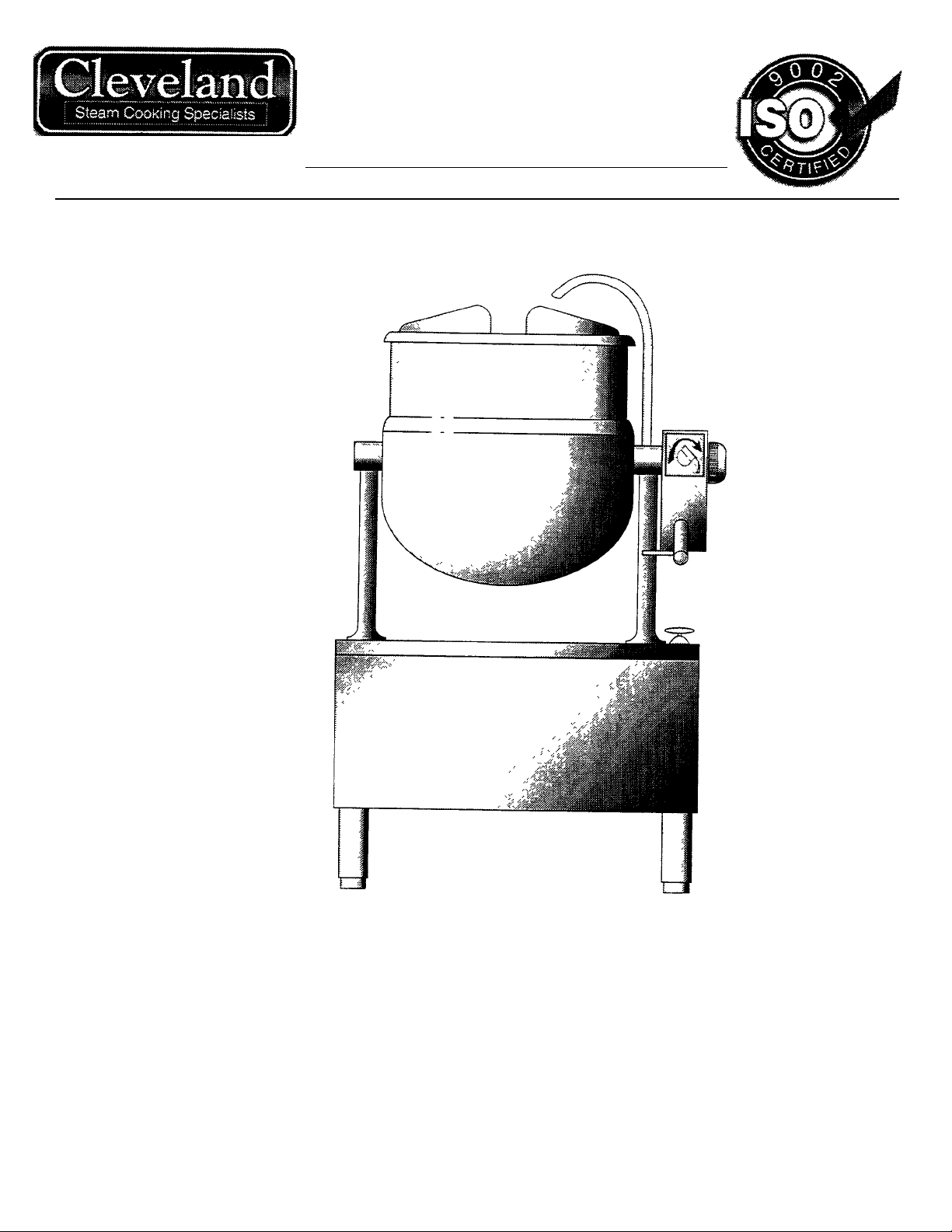
12 Gallon Kettle on
Stand
MODEL: SD650K12-BC
CLEVELAND RANGE INC.
1333 East 179th St. Cleveland,
Ohio U.S.A. 44110
Toll Free 1-800-338-2204
INSTALLATION, OPERATION AND
SERVICE MANUAL
Page 2

TABLE OF CONTENTS
Installation
Operating, Care &
Cleaning Instructions
Service Parts
Maintenance
General 1
Inspection 1
Shipping Damage Instruction 1
Installation 1
Clearance Requirements 1
Steam 1
Condensate 1
Water 1
Final Installation Check 1
Operation 2
Care & Cleaning 2
Steam Control Assembly 3-4
Tilting Gearbox Assembly 5-6
Plumbing Assembly 7-8
General Maintenance …9
Pressure Relief Valve Testing Procedure 9
Steam Trap 9
Warranty 9
Troubleshooting Guide 10
Steam Flow Rating of Steam Generators 10
Steam Flow Rating Requirements for Kettles 10
Page 3

INSTALLATION
GENERAL
Installation of the unit must be accomplished by
qualified installation personnel working to all
applicable local and national codes Improper
installation of product could cause injury or damage
This unit is built to comply with applicable standards
for manufacturers Included among those approval
agencies are UL, NSF ASME/NtI Bd , CSA, ETL,
CE, and others Many local codes exist, and it is the
responsibility of the owner/installer to comply with
these codes
INSPECTION
Before uncrating, visually inspect the unit for
evidence of damage during shipping If damage is
noticed, do not unpack the unit, follow shipping
damage instructions
SHIPPING DAMAGE
INSTRUCTIONS
If shipping damage to the unit is discovered or
suspected, observe the following guidelines in
preparing a shipping damage claim
CLEARANCE REQUIREMENTS
For complete details see the SPECIFICATION DRAWING
at the back of this manual
CLEARANCE REQUIREMENTS TO COMBUSTIBLE
AND NONCOMBUSTIBLE SURFACES:
Right - 4' Left - 0 Back - 0
STEAM
All steam plumbing to and from the kettle and steam
boiler should be thoroughly cleaned and inspected
for dirt and debris before final connection to the
kettle are made
Kettles require a minimum 1/2' i p s pipe, 10-45 psi
steam pressure If the steam supply pressure
exceeds 45 psi, a pressure reducing valve is
required The steam inlet is at the right side of the
kettle, as seen from the front
CONDENSATE
The condensate line is limited to a maximum rise of
10 feet in order for the steam pressure to
adequately force the condensate through the
plumbing Any higher rise requires a pump
1. Write down a description of the damage or the
reason for suspecting damage as soon as it is
discovered This will help in filling out the claim
forms later If possible, take a polaroid picture
2. As soon as damage is discovered or
suspected, notify the carrier that delivered the
shipment
3. Arrange for the carrier's representative to
examine the damage
4. Fill out all carrier claims forms and have the
examining carrier sign and date each form
INSTALLATION
Carefully remove unit from shipping carton and
position unit in desire location Place a carpenter's
level on the kettle rim and level the stand using the
level adjustable feet
Install service connections as required
WATER
The water faucet, with swing spout, requires 1/2
inch 0 D copper tube plumbing for cold water supply
to the faucet
FINAL INSTALLATION CHECK
1. Partially fill the kettle with water
2. Slowly turn the steam supply valve s knob to the
open position
3. Release the safety valve ensuring that the steam
escapes freely Stay clear of steam exhaust
when releasing the safety valve
4. Observe that the water in the kettle comes to a
boil
5. Close the steam supply valve
6. Drain off the water by tilting the kettle
Page 4
OPERATION, CARE & CLEANING
6.
To empty kettle,
INSTRUCTIONS
CLEVELAND STEAM COOKING EQUIPMENT IS INTENDED FOR COMMERCIAL USE
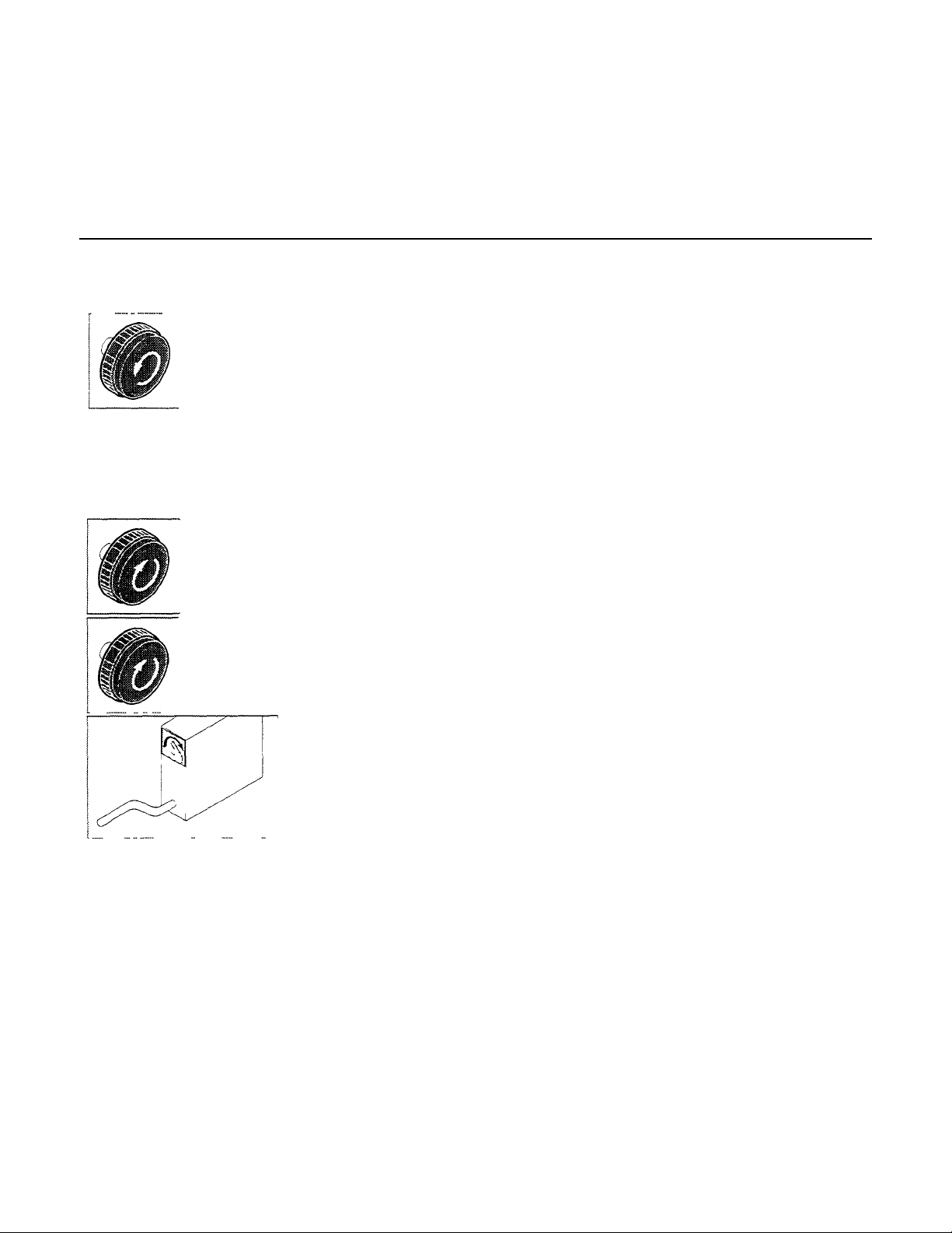
OPERATION
1. Ensure that there is an adequate steam
supply to the kettle.
2. Turn the steam control valve to the
final open position by turning the
knob counter-clockwise, then allow
the kettle to preheat.
NOTE: When cooking egg and milk
products, the kettle should NOT be preheated, as
products of this nature adhere to hot cooking
surfaces. These types of foods should be placed in
the kettle before heating is begun.
3. Fill kettle with product to desired level.
4. When the product has reached the
desired temperature, regulate the
heat, as required, by turning the
steam control valve for less steam,
and therefore, a lower temperature.
5. When cooking is complete, close
the steam control valve by turning the
knob.
ONLY BY PROFESSIONALLY TRAINED PERSONNEL.
NOTE: As with cleaning food soil from any
cookware, an important part of kettle cleaning is to
prevent foods from drying on. For this reason,
cleaning should be completed immediately after
cooked foods are removed. Please read the
following "Care and Cleaning" instructions for
detailed kettle and stand washing procedures.
CARE AND CLEANING
Your kettle must be cleaned regularly to maintain its
fast, efficient cooking performance, and to ensure its
continued safe, reliable operation.
WARNING: Do not use chloride base detergents.
1. Prepare a warm water and mild detergent solution
in the kettle.
2. Remove food soil inside the kettle using a nylon
brush. Do not use a metal bristle brush as this
may permanently damage the kettle's stainless
steel surface.
3. Loosen food which is stuck to the kettle by
allowing it to soak at a low temperature setting.
4. Tilt kettle forward to drain wash water.
turn handle
clockwise.
FOR KETTLE/STEAMER COMBINATIONS:
If the boiler in a steamer is supplying steam to a
kettle, always heat the kettle first. After the kettle
contents are heated and the boiler's steam pressure
returns to normal, the steamer may be used.
Pressure steamer compartments should be
sequentially started, and preheated before cooking.
5. Rinse kettle interior thoroughly, then drain the
rinse water.
6. Using mild soapy water and a damp sponge,
wash the exterior of the kettle and stand rinse,
and dry.
7. Leave the cover off when the kettle is not in use.
NOTE: For more difficult cleaning applications one
of the following can be used: alcohol, baking soda,
vinegar, or a solution of ammonia in water Avoid the
use of chloride cleansers, which may damage the
kettle's or stands stainless steel surface.
WARNING: Steel wool should never be used for
cleaning the cooking chamber of the kettle. Particles
of steel wool become embedded in the cooking
surface and rust, which may corrode the stainless
steel.
Page 5

Steam Control Assembly
Page 6

STEAM CONTROL ASSEMBLY
ITEM NO. PART NO. DESCRIPTION QTY.
1 KE52697 Lock Nut, 1/2" NPS 2
2 FA32500 Lockwasher 2
3 FA30502 Washer, satin coat 2
4 KE50467 Washer, Foot 2
5 KE50463 Service Pipe 2
6 KE00203 Leg Assembly 2
7 FA11056 Binding Head Screw, 6-32 x 1/2° Ig 2
8 KE50458 End Cap, condensate return 1
9 KE504551 Trunnion, condensate return 1
10 FA00018 "0" Ring 1
11 FA00117 "0" Ring 4
12 KE54752 Trunnion 1
13 FA11509-1 Bolt, 1/2-13x3/4"lg 1
14 FA11089 Binding Head Screw, 8-32 x 1/4" Ig 1
15 KE51713 Washer, steam valve 1
16 FA00110 "0" Ring 1
17 KE50459-1 Operating Stem 1
18 KE51888 Retaining Washer 1
19 SE00028 Steam Control Knob (includes Item #18 & 20) 1
20 FA11092 Binding Head Screw, 8-32 x 1/2" Ig 1
21 KE54729 Gear Box Cover 1
22 FA11146 Binding Head Screw, 8-32 x 3/8" 4
Page 7

TILTING GEARBOX ASSEMBLY
Page 8

TILTING GEARBOX ASSEMBLY
ITEM NO. PART NO. DESCRIPTION QTY.
1 -16 KE02062-1 Tilting Gearbox Assembly 1
1 KE02060 Gearbox Housing 1
2 KE50198 Bearing, trunnion 2
3 KE54739-2 Bearing, tilt shaft 2
4 KE54737 End Housing Spacer, tilt shaft bronze 1
5 KE54738-3 Washer 1
6 KE50306-1 Tilt Shaft 1
7 KE52192 Bearing Washer 2
8 KE52191 Bearing 1
9 KE50426-3 Spacer, worm gear 1
10 KE50315 Worm Gear 1
11 FA95005 Tension Pin 1
12 KE54738-1 Washer 2
13 KE02059 Segment Gear and Spacer Assembly 1
14 KE02061 Trunnion Bearing Housing Holder Assembly c/w Bearing 1
15 FA10485 Hex Head Bolt 1
16 FA20008 Hex Nut 1
Page 9

Page 10

PLUMBING ASSEMBLY
ITEM NO. PART NO. DESCRIPTION QTY.
1 KE50826 Faucet Spout 1
2 FA95022 Retaining Ring 1
3 FA00016 "0" Ring 1
4 KE51736 Long Faucet Nut 1
5 SD50097 Flanged Nut, 3/4" NTP Chrome Plated 1
6 KE51585 Faucet Spout Fitting 1
7 SD50098 Locknut, 3/4" NPT 1
8 FI00266 Coupling 1/2" NPT 1
9 SD50101 Copper Tube, 31 1/2" Ig
10 FI00169 Tee 1/2" NPT 1
11 KE51723 Pressure Relief Valve, 1/2" NPT 1
12 KE51899-1 Valve, cold water 1
13 FA95010 Jam Nut, #3/4-10 4
14 KE51340 Leg 4
15 SD50000 Strainer Assembly 1
16 SD50042 Radiator Hose, 4" Ig 1
17 FI05131 Hose Clamp 2
18 SD50043 Nipple, threaded one end only 1
19 KE51367 Check Valve, 1 1/4" NPT 1
20 FI00670 Nipple 1
21 FI00136 90° Street Elbow, 1 1/4" NPT 1
22 FI00191 Cap, 1 1/2" NPT 1
23 KE00648 Drain Pipe Assembly 1
24 FI00044 90° Elbow, 1 1/2" NPT 1
25 FI05027 Pipe Strap 2
26 F105049 Male Connector 1
27 FI05077 Male Elbow 1
28 SD50027 Steam Trap 1
29 F105049 Male Connector 1
30 KE51249 Strainer, 1/2" NPT 1
31 FI00596 Nipple, 1/2' NPT 1
32 FI00266 Coupling, 1/2" NPT 1
33 KE52697 Lock Nut, 1/2" NPS 2
34 FA32500 Lockwasher 2
35 FA30502 Washer, satin coat 2
36 KE50467 Washer, Foot 2
37 KE50463 Service Pipe 2
Page 11

MAINTENANCE
ALL SERVICE MUST BE PERFORMED BY A
QUALIFIED SERVICE TECHNICIAN.
This kettle requires very little preventative maintenance other than daily cleaning. The
pressure relief valve must be tested twice a year.
PRESSURE RELIEF VALVE TESTING
PROCEDURE
WARNING
Kettle will be hot. Use gloves for protection.
The pressure relief valve must be checked at least
twice a year as part of the normal maintenance
performed.
1. Open steam valve and preheat kettle.
STEAM TRAP
Each kettle is equipped with a steam trap in the line
of the kettle outlet to the drain, to remove line
condensate that forms inside the steam jacket. A
good steam trap at startup releases air and wet
steam into the drain line for a few minutes, then
holds the steam jacket. During cooking, the trap
periodically releases accumulated condensate. If the
kettle's cooking performance becomes inadequate
after long use, replacement of the steam trap with a
new one may restore kettle operation to peak
efficiency.
2. Stand to the side of the pressure relief valve
discharge tube and pull ring three or four times
to insure free movement. Hold valve open for
two seconds each time, insuring there is rapid
steam escape each time.
3. If valve appears to be sticking replace pressure
relief valve. If foreign material is discharged,
replace pressure relief valve and eliminate the
source of contamination.
WARRANTY
Our Company supports a worldwide network of
Maintenance and Repair Centers. Contact your
nearest Maintenance and Repair Centre for
replacement parts, service, or information regarding
the proper maintenance and repair of your cooking
equipment.
In order to preserve the various agency safety
certification (UL, NSF, ASME/NtI Bd , etc ), only
factory-supplied replacement parts should be used.
The use of other than factory supplied replacement
parts will void warranty.
Page 12

TROUBLESHOOTING GUIDE
250,000
150 44
2
7 90 2.6
Electric:
Probable Cause
Remedy
3.
Food batches are not always the same.
PROBLEM
Remedy
This section contains information intended for use by Authorized Service Personnel only.
PROBLEM
A/ Kettle heats too slowly or does not come to a boil.
1. Inadequate steam flow.
Check for correct steam using chart below.
If kettle is connected to a steamer and powered by a
generator the units should be operated sequentially
(kettle boiling first, then start steamer).
2. Steam trap not operating properly. The trap should open periodically to
dump condensate, then close. If it does
not open or close it should be cleaned
or replaced.
When checking make certain that the original state
(i.e.fresh or frozen) and quantity of food product is the
same.
B/ The trunnion housing leaks steam.
Probable Cause
1. Trunnion "0" rings are worn.
Replace "0" rings (see STEAM CONTROL ASSEMBLY
drawing).
Gas Input
BTU/Hour
STEAM FLOW RATING OF
STEAM GENERATORS
Steam Output
Lbs./Hour
Boiler
H.P.
Capacity
Gal./Lit.
STEAM FLOW RATING
REQUIREMENTS FOR KETTLES
Fast Medium Stock
Cooking Cooking Kettle
100,000 60 1 7
160,000 95 28 5/17 11 9 6
200,000 125 36 10/42 22 18 11
300,000 180 5.2 25/95 55 44 28
Electric
KW Input
18 60 1 7
24 70 2.0
36 120 3.5
48 150 44
40/151 88 70 44
60/227 132 105 66
Above shows Ibs per hour with 10-15
psig steam at the kettle The use of
higher steam pressures (20-25 psig) will
reduce heat-up time 5-20%
10
Page 13

SPECIFICATION DRAWING
 Loading...