

Cleveland PDL-2K Service Manual

Cleveland Range
UNITED STATES
CANADA
REPAIR
MANUAL
PEM24/36/48-2/3K
PGM160/200/250/300-2/3K
PDL/PDM/PDP-2/3K
Model No. PSM-2/3K
1333 East 179th St.
Cleveland, Ohio 44110
Phone: (216) 481-4900 • FAX: (216) 481-37S2
Garland Commercial Ranges • 1777 Kamato Rd.
Mississanga, Ontario CN L4W 1X4
Phone: (416) 624-0260 • FAX: (416) 624-0623
PS-02

Installation Instructions For Steam Generators, Steamers,
Steamer/Kettles: Gas — Electric — Steam Coil
Installation Instructions For AS Models
1) These instructions must be retained By the owner / user tor future referenca. For installation only in noncombustible
locations. Gas units am only to be installed in areas that have provisions tor adequate air supply
2) Position: For proper operation and drainage, steam generator must be level. It must be set near a floor drain. Attach
1 1/2" piping to an drain connections to carry exhaust steam away from the cabinet. Ends of drain lines must vent to
atmosphere to avoid back pressure. Allow a MINIMUM of 6" clearance to the rear and sides of the equipment. The
surrounding area must be free and clear of combustibles.
3) install in accordance with local codes and/or the National Electric Code ANSI/NFPA No. 70-1984. installation in
Canada shall be in accordance with the Canadian Electric Code CSA Standard C22-1. A unit mat a connected to
electricity must be grounded. A wiring diagram is provided inside the relay box.
4) Connect supply lines for 140 — 160° hot water, and cold water, to the unit. Water pressure must Be maintained
between 35 and 60 PSI. Locations and pressure data are shown on the connection drawing. Long hot water lines
should be at least 1/2" IPS. Rush water supply lines thoroughly before connecting. Use water which is low in total
solids content and low in gas content. to prevent internal scaling, pitting and corrosion of the steam generator and
carry-over of minerals into the steam. Water which is fit to drink can still contain highly detrimental impurities. Refer
Water Quality Requirements page.
5) Turn on water supply to steam generator. Water valve is inside of base.
6) Connect fuel supply
Do not store or use gasoline or other flammable vapors and liquids in the
FOR YOUR SA FETY
vicinity of this or any other appliance.
For Steam Coil Steam Generators —
— Connect steam supply Location is shown on the connection drawing. Incoming steam pressure must be
regulated between 35 and 45 pa (30 —45 psi for pressure steamers), Install a strainer ahead of the regulating valve.
Flush line thoroughly before connecting.
— Connect the outlet end of the steam coil to an inverted bucket trap. Fill trap with water before installing.
— Connect electricity if unit is equipped with electrical controls. Permanent 115V connection is required. Junction
box location is shown on the connection drawing. Unit must be electrically grounded by the installer. For
Gas Fired Generators-
— Post in a prominent location, instructions to be followed in the event the user smells gas This information
shall be obtained by consulting the local gas supplier.
— Connect gas: Location and pressure data are shown on the connection drawing, installation snail be in
accordance with local codes, or in me absence of local codes, with the National Fuel Gas Code ANSI Z223-1 —1984
Installation in Canada shall be in accordance with Installation Codes tor Gas Burning Appliances and Equipment B149.1
and B149.2 Use a gas pipe joint compound which is resistant to LP gas. Test all pipe joints for leaks with soap and water
solution. Allow 12 inch clearance on right side of all Gas Fired Steam Generator models for servicing gas burners and tor
proper operation. 12" clearance also provides adequate air openings into me combustion chamber. Never obstruct the
flow of combustion and ventilation air. The appliance and its individual shutoff valve must be disconnected from the gas
supply piping system during any pressure testing of that system at test pressures in excess of 1/2 psig (3.45 kPa). The
appliance must be isolated from the gas supply piping systern by closing its individual manual shutoff valve during any
pressure testing of the gas supply piping system at test pressure equal to or less than % psig (3.45 kPa).
— Connect electricity if unit is equipped with electrical controls. Permanent 115V connection a required.
Junction box location is shown on the connection drawing. Unit must be electrically grounded by the installer.
— Lighting and Shutdown Instructions: Rip electrical switch on Open water valve. Open gas valve. Slightly depress
and turn control knob to "off" for 5 minutes before lighting gas. Turn control knob to "pilot" depress it completety and light
pilot burner. Continue to hold knob in tor about 60 seconds, then release. Pilot burner a lighted through hole in panel at
bottom of steam generator. Never leave panel off. as this will damage controls. Turn control knob to "on". Depress
electrical "reset" switch tor main burner ignition. Burners will not light without water in the steam generator. For main
burner off. with pilot on, turn control knob to "pilot"- For main and pilot burner oft slightly depress and turn control knob to
"off" Flip electrical switch off. For Electrical Steam Generators
— Connect electric power Location is shown on the connection drawing. Provide connection as required by your unit
Electric supply must match power requirements specified on data plate attached to base. Wiring must be adequate to
carry required current at rated voltage. A separate fused disconnect must be supplied and instailed. Unit must be
electrically grounded by the installer.
CLEVELAND RANGE C0_ 1333 EAST 179th ST., CLEVELAND, OHIO 44110 LITHO IN U-S-A-
Manufacturer reserves right of design improvement or modification, as warranted.

7) Turn on electricity at control circuit switch on steamer console A red light glows when electricity is on. If water level is correct
steam generator will operate by pressing me "reset" button. Heaters will not work without water in the steam generator This
manual reset button must be pressed to start up the generator initially, and to restart the steam generator after every shut oft. or
power interruption. No attempt should be made to operate the equipment during a power failure.
8) Check 10 make sure that me water in the sight gauge glass automatically stays at about 2/3 full when the unit is started up.
9) When installation is complete and tree of leaks, refer to Operating Procedures sheet.
Instructions For Steam Generator Care
Protect your steam generator, prolong its life and preserve its performance by giving it the required daily attention, on a regular
schedule. Follow servicing instructions for your steam generator which are printed on Data Sheet 260-LC in your Owner s Manual,
and also or an adhesive label attached to the unit. To obtain an additional data sheet or label carrying servicing instructions, write to
the Cleveland Range Company.
No work should be dorm on the steam generator while it pressurized or hot. Service of the steam generator
should only be performed by a trained and experienced service technician, thoroughly My familiar with servicing
steam generators. When maintenance or repairs are required, contact a located food service equipment service
agency, or call the factory, or a factory representative for the name and address of one in your area.
WARNING
Steam Generator (Boiler) Safety
Rigid regulations govern the design and construction of a boiler. However, the responsibility for the safe and efficient
operation of a boiler shifts to the owner/user after the boiler leaves the factory.
A sound boiler if improperly installed, or if improperly maintained, or if improperly repaired, will create a dangerous situation and
may cause injury to personnel.
Most sates, provinces and some cities nave a boiler safety law. Many underwriters require that their clients' boilers comply with these
boiler safety laws. These safety laws call for action by the boiler manufacturer and action by the boiler owner/user.
As a manufactur er. The Cleveland Range Company delivers steam generators built me ASME Boiler Code. Section IV. which have
been inspected by a National Board Inspector. Also. each Cleveland Range Company boiler is built to comply with the boiler safety
law of the state t o which it is sent
Safe and Effecient Boiler Operation Depends on Proper Installation
Install the boiler in compliance with following regulations, where they apply:
— The National Fuel Gas Code. ANSI Z223.1-1984
—— installation Codes for Gas Burning Appliances and
Equipment B149.1 and B149.2
— The Cleveland Range Company Installation instruc-
tions
— The National Electrical Code ANSI/NFPA No.70-1984
The water for the boiler should be analyzed by a reputable boiler water specialist to see if the quality will permit safe and
efficient boiler operation. Water treatment is becoming increasingly necessary because the quality of water sources is
deteriorating. although treatment will not be required in every case. A boiler will not operate properly for very long if the
water causes boiler corrosion or scale. Even water which 13 safe to drink may be detrimental to a boiler. Refer to Water
quality Requirements page for details.
Safety Requires Periodic Inspection and Maintenance
Any leaks around the boiler's hand note plate must be Quickly stopped. Small leaks, it unchecked, cause corrosion and
pitting on the boiler face around the hand hole gasket, making it unsealable.
Application of undue stress on the parts that are used to seal the boiler's hand hole opening, in an attempt to seal an
unsealable opening, by sledging the handle of the wrench, by increasing the leverage of the wrench a length of pipe. or
by other means, is dangerous because it may result the breakage of parts, or injury. No attempts should be made 10
tighten up the nut on the retaining stud beyond the recommended 15 foot pounds of torque.
When a repair affecting the safety of the boiler is necessary. call a National Board Inspector consultation and advice as to
the best method of making the repair, so that the completed work will get his approval. Repairs to the boiler must conform
to the applicable provisions in the ASME. Code or the National Board Rules for Repairs.
A boiler will last many years before it has to be retired from service. Periodic inspection will reveal the approaching
retirement time. It a better to schedule a convenient replacement time than to wait for the boiler to fail. When a boiler older
man 10 years is replaced, the entire steam generator base assembly should be replaced for a number reasons:
— Replacement parts become increasingly difficult to obtain for older controls.
— Dependable performance of the new controls can be assured for a longer time.
— The new steam generator, including controls, will comply with the latest industry and safety standards.
CLEVELAND RANGE CO., 1333 EAST 179th ST., CLEVELAND, OHO 44110
— The local and municipal building code (plumbing ana
electrical
— The state and city boiler laws
— The recommendations of the owner/user's under-writers

PRESSURE STEAMER OPERATING INSTRUCTIONS
NOTE: These instructions pertain to steamers equipped with self-contained steam generators (boilers). Forr steamers direct-connected to a
remote (in -house) steam source, disregard those instructions which are directly and solely related to the self-contained steam generator. These
instructions are to be retained by the owner/user for future reference.
1A Open the cabinet base door and close the drain valve if it is open.
B Make sure the hot and cold water supply valves are open
C For steamers equipped with a gas-fired steam generator (boiler) follow the lighting instructions noted on the instruction label displayed on
the unit before continuing to instruction in item 2.
2 Flip the t oggle switch on front of the cabinet console to "ON" The red console light should then glow and the boiler will automatically
begin filling with water (if it is not already full).
3 After approximately five minutes (after water appears in the sight gauge), depress the ""START" reset button on the console. This will
energize the electric heater elements or ignite the gas burners. This cannot be accomplished until the boiler is full of water.
4 in approximately 15 minutes you will notice the console's steam pressure gauge register 5 pounds. (10 pounds if the boiler is also supplying
steam to a kettle- The upper pressure gauge will register 5 pounds.) You can now preheat the cooking compartments.
5 Compartments should be preheated before use and should be kept hot between loads. If a Kettle and steamer are to be used at the same
time, always heat the kettle unit first. When kettle contents begin to simmer, preheat the steamer compartments- When pressure on the
boiler gauge returns to 10 pounds, cooking may begin in the steamer
6 Close and latch door securely. Turn bar handle clockwise until the door gasket just touches the compartment face
7 Start steam supply by pulling steam valve handle out. If fined with automatic timer, set timer for 5 minutes. At the start, compartment
thermostatic traps should release air and wet steam tor about two minutes, then shut off.
8 Seal compartment door by turning bar handle clockwise just until steam leakage stops. DO NOT OVERTIGHTEN.
9 At the completion of the 5 minute preheatin g cycle, push steam valve slowly in, to avoid boilovers. This shuts off the steam supply and also
depressurizes and drains the compartment. If fitted with an automatic timer, the steam shuts off automatically and a bell rings when the
timer reaches zero. Setting the timer to "Off" stops the bell.
10 To open compartment door, turn bar handle counter-clockwise and delatch.
11 Cooking can now begin by following the above operating steps #6 through #10, but setting the timer for the required cooking time- At the
end of a cooking cycle 40 minutes long or longer, or when defrosting frozen foods, wait at least two minutes for the compartments) to
depressurize and drain before opening the compartment door.
CAUTION: After each cooking cycle, ensure that all water is draining, and not accumulating in the
compartment. Should a drain become obstructed, it must be cleared before attempting to cook in that
compartment.
12. At the end of each day's operation, flip the console toggle switch to the "Blowdown" position, open t he door in the cabinet base and open
the boiler drain valve, (red handle). This "Blowdown" drains the boiler and helps to keep it dean. When the boiler is empty, flip the console
toggle switch to the "OFF" position and dose the boiler drain valve
13. It is recommended that the boiler be refilled with water after the "Blowdown" is performed. This can be accomplished by flipping the
toggle switch to the "ON" position for a period of five minutes and then returning the switch to the "OFF" position.
1. Blow down the steam generator daily.
2. A periodic boiler inspection must be performed by a qualified serviceman to prolong its life and to minimize service calls
3. At the end of each day's operation, wash the pan slides, drain screen covers, door gaskets, and compartment interiors with mild detergent
and warm water- Thoroughly rinse with clean water. Rinse water should drain freely through the compartment drain openings. If it does not,
the drain must be cleaned before using the steamer.
4. Once a week. flush each compartment drain with a food service equipment drain cleaner and a deliming solution
5 Once every three months, shut off the water supply (hot and cold), and clean the water line strainers.
6. Compartment thermostatic traps can be disassembled and cleaned, by hand or in a mechanical dishwasher. This procedure is recommended
if the traps act sluggishly, as they may if contaminated by grease or other film. If cleaning fails to restore the trap's proper functioning,
replace the trap. For more detailed thermostatic trap servicing instruc tions., refer to Data Sheet 260-LH.
TO PROLONG LIFE AND MINIMIZE SERVICE REQUIREMENTS
CLEVELAND RANGE. INC., 1333 EAST 179th ST., CLEVELAND, OHIO 44110
Manufacturer reserves right of design improvement or modification, as warranted.
1

7. Shelves, drain screens, and pan slides arc stainless steel, and can be washed safely in a mechanical dishwasher.
8. Exterior Care: Allow steamer 10 cool before washing. Use the same cleaners and cleaning procedures as for other kitchen surfaces of stainless
steel and aluminum. Mild soapy water, with a clear water rinse, ;s recommended. DC no: allow water to run into electncal controls- Always
turn off equipment power before using water to wash equipment.
9. Compartment Door Care:
a. When doors are closed tor preheating or cooking, turn bar handle just enough to stop steam leakage. Overtightening shortens gasket life.
b. When doors are open or unlatched. Do not turn bar handle.
c Always leave compartment doors ajar when not in use, to extend gasket life and to prevent gaskets from adhering to the steamer.
Unnecessary compression of a gasket shorten it s life.
d Keep bar handle screws clean. Lubricate frequently but not excessively.
e. Door gaskets provide many months of service when care is taken to operate doors properly. When a gasket finally wears and does not
maintain an effective seal, it must be replaced. Door gaskets can be replaced easily without special tools or cement, and the steamer may
be used immediately afterwards- Remove the old gasket and dean the channel. being careful not to damage the channel. The new gasket
can then be pressed into place. Insert the gasket in the corners of the channel first, adjusting the slack evenly between the comers - Then
work from the comers to the center. Ridges hold the gasket firmly. The gasket is designed to be oversize, so once it is compressed into the
door's channel, it remains firmly in place.
PRESSURE STEAMER SAFETY
FOR YOUR SAFETY
Do not store or use gasoline or other flammable vapors
and liquids in the vicinity of this or any other appliance.
Being the owner of a steamer carries with it the responsibility for Keeping it in as safe a condition as when it was shipped from
the factory. Safe steamer operation dictates that every pressure steamer must have the following safety inspection at least every
12 months.
1. Steam Valve Linkages
Have a qualified serviceman examine the steam valve linkages which are attached to the inlet and exhaust valves' operating
handles on the left side of the steamer. This pivoted linkage, which is attached to both the steam inlet valve and the steam
exhaust valve, must prevent the door's latch from disengaging from its catch when the steamer compartment is pressurized. It
is important that the linkage operates as described so that the steamer door cannot be opened when the compartment is
pressurized.
It is also important that when the steam valve is closed, the exhaust valve should open. The proper operation of the steam inlet
valve and the steam exhaust valve should be confirmed and observed while the steam is on.
2. Pressure Gauge Check each pressure gauge. Gauge pointer must return to zero when the steam generator is shut down. Look
for signs of water, rust, corrosion, or scale, inside the pressure gauge. A faulty pressure gauge should be replaced
immediately.
a Door Gaskets
Inspect and replace compartment door gaskets once a year, or sooner if they are torn or hardened. The use of a hardened gasket
produces undue stress in the parts which comprise the door enclosure and may result in breakage and injury.
4. Compartment Thermostatic Trap
Observe compartment thermostatic traps for proper operation. A good compartment trap, at start-up of a cooking cycle, is
normally open and releases air and wet steam briskly for a few minutes. then holds steam within compartment. If brisk venting
doesn't begin immediately at start-up, or if brisk venting continues without stopping, and the compartment trap is over a year
old, it should be cleaned, or a new one installed- Refer to data sheet 260-LH for details
5 Compartment Steam Exhaust Valves and Drain Valves
Make sure that the compartment steam exhaust valves, and the drain lines attached to them, are free of food buildup internally
and are venting freely to the atmosphere. If drain lines from other steam-consuming equipment have been connected to the
drain line from the steamer, the other drain lines should be disconnected. Never operate a compartment without the drain
screen cover in place.
6. Refer to separate data sheets for steam generator operation, maintenance, and safety procedures.
WARNING
Service of steam cooking equipment should only be performed by a trained and experienced service technician,
thoroughly familiar with servicing steam equipment. No work should be performed on the steamer while it is
pressurized or hot. Be sure all energy sources are shut off before the start of any work. When maintenance or repairs
are required, contact a local food service equipment service agency, or call the factory. or a factory representative, for
the name and address of one in your area.
CLEVELAND RANGE, INC., 1333 EAST 179th ST., CLEVELAND, OHIO 44110
Manufacturer reserves right of design improvement or modification, as warranted.
2
PRESSURE STEAMERS: THERMOSTATIC TRAP AND
COMPARTMENT DOOR GASKET REPLACEMENT
The thermostatic trap and door gasket on your steamer stop the escape of steam from the compartment during operation. Steam leakage from
either source will cause loss of pressure. which will result in longer cooking time. wasted Steam and
excessive condensation.
To keep your steamer operating at peak efficiency. thermostatic traps and compartment door gaskets require periodic replacement Frequency
of replacement vanes from one piece of equipment to another depending on the amount of usage, and frequency and quality of maintenance.
A normal thermostatic trap at Startup releases air and wet steam briskly for the first few minutes, then holds steam within the compartment.
During cooking, the trap will also release accumulated condensate ana a small amount of air
It brisk venting doesn't begin immediately at startup or if brisk venting continues for much longer than two minutes. and the compartment
trap is over a year old, it should be cleaned, or removed and a new one installed.
A compartment trap less than a year old may act sluggishly only because it is contaminated by grease and other film.
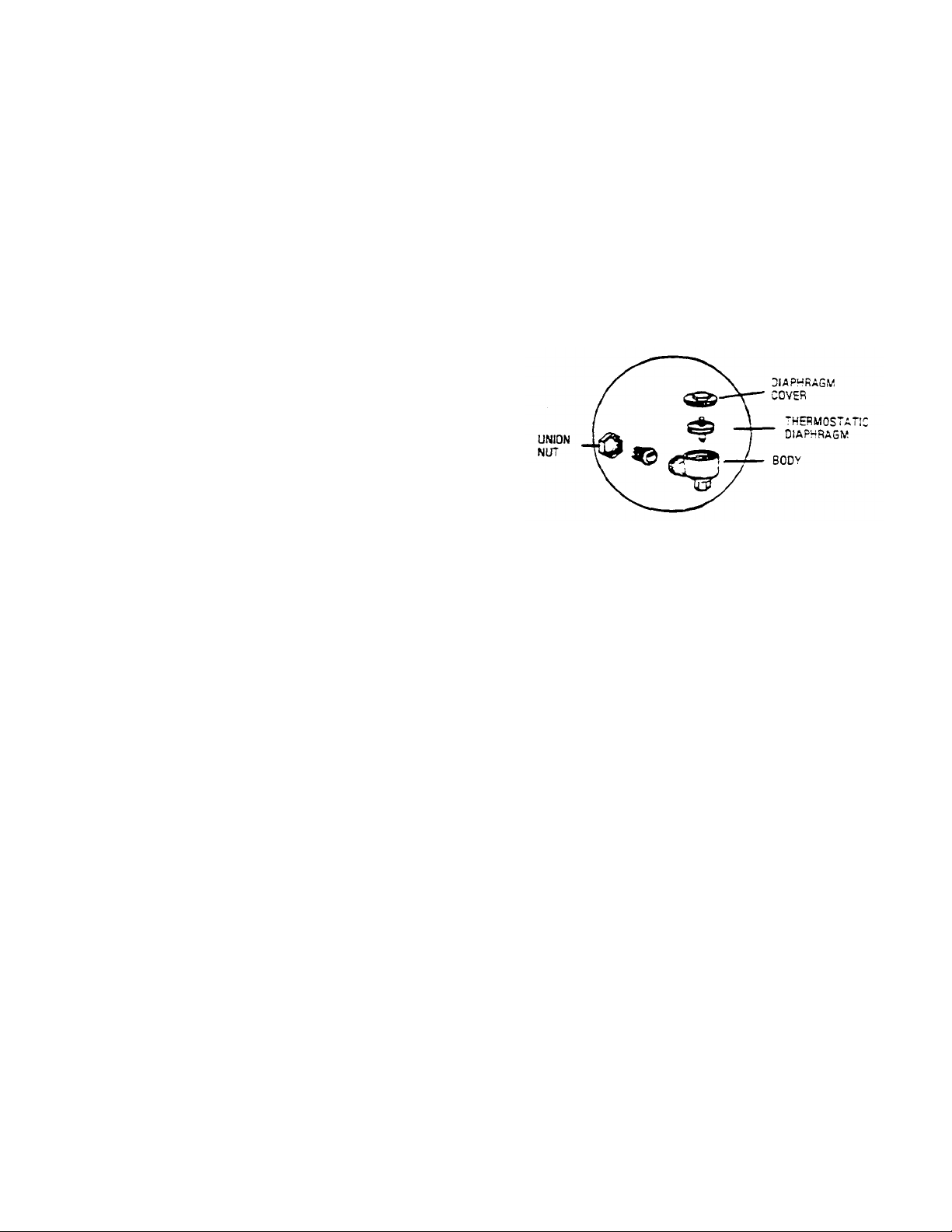
To remove a thermostatic trap. unscrew the union nut
as shown on the sketch.
To clean the trap. unscrew the threaded! diaphragm cover from
the body and wash the entire assembly. A more thorough cleaning
can be accomplished by removing and disassembling the trap. and
washing the entire assembly in a mechanical dish washer.
With proper tools, the threaded diaphragm cover can be unscrewed
from the body. and the thermostatic diaphragm can be unscrewed
from the diaphragm cover, if the trap does not work property after
thorough cleaning. install a new one.
If the steamer is used heavily for cooking foods contain ing large
amounts of fat or starch. periodic cleaning is recommended as a routine procedure
Replace the gaskets on compartment doors once a year. or sooner if they are torn or hardened.
Door gaskets can be replaced easily without special tools or cement, and the steamer may be used immediately afterwards.
Remove the old gasket and clean the channel, being careful not to damage the channel. The new gasket can then be pressed into place.
insert the gasket in the corners of the channel first, adjusting the slack evenly between the comers. Then work from the comers to the center.
Ridges hold the gasket firmly. The gasket is designed to be oversize, so once it is compressed into the door's channel, it remains firmly in
place.
COMPARTMENT THERMOSTATIC TRAP
COMPARTMENT DOOR GASKET REPLACEMENT
WARNING
Service of steam cooking equipment should only be performed by a trained and experienced service technician,
thoroughly familiar with servicing steam equipment, No work should be performed on the steamer while it is
pressurized or hot, Be sure all energy sources are shut off before the start of any work. When maintenance or
repairs are required, contact a local food service equipment service agency, or call the factory, or a factory
representative, for the name and address of one in your area.
CLEVELAND RANGE CO.. 1333 EAST 179th ST, CLEVELAND, OHIO 44110
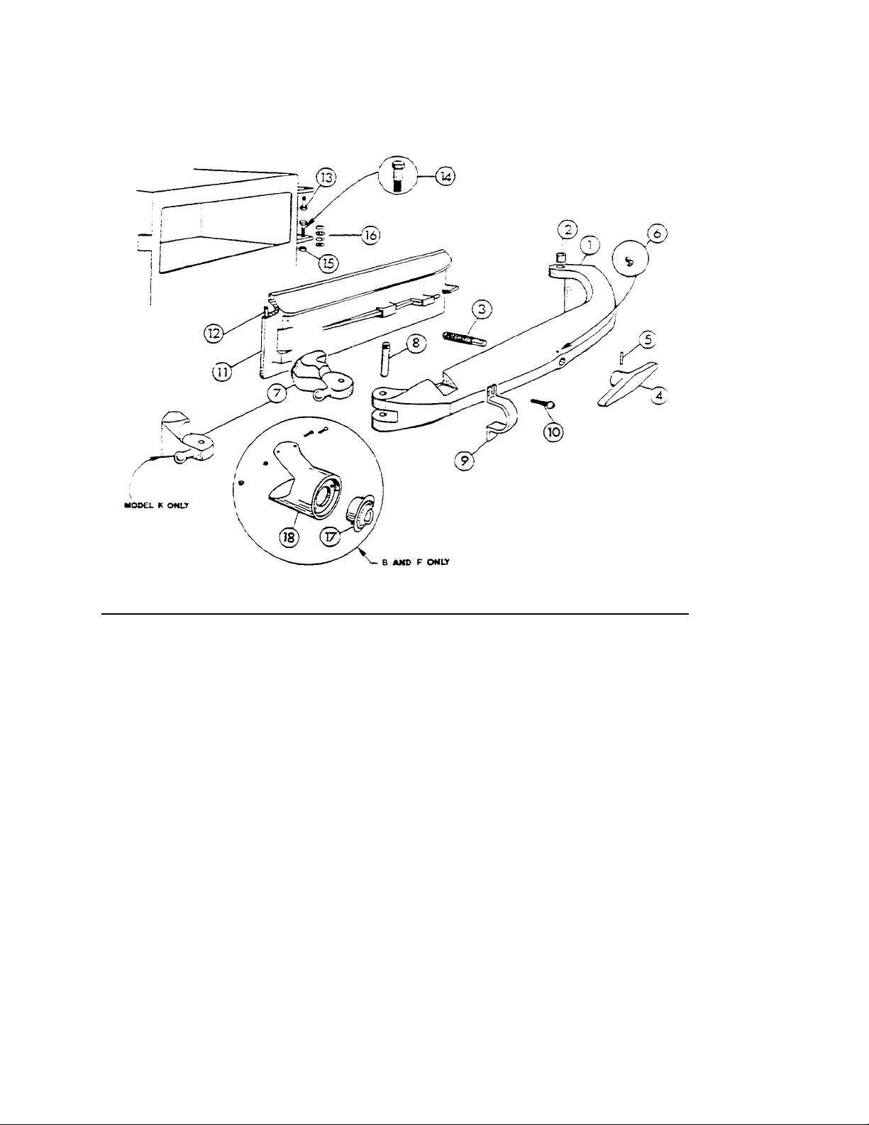
MODELS B, C, F, K PRESSURE STEAMERS DOOR
1 25303
Door Ann With Bushings
— Model B
&
C, Polished
25304
Door Arm With Bushings
— Model F
&
K. Polished
2
02568
Door Arm Hinge Bushing
(2
Req
uired) 3 41370
Standard Door Ann Screw With Ball
(1" x 8
thread)
41371
Oversize Door Ann Screw With Ball 1 3/32" x
8
thread)
4
081001
Screw Handle Bar, Polished
5
16305
Pin 6 15250
Oil Cup
7
122011
Door Ann Latch
— Model B, C.
&
F Chrome Plated
122021
Door Ann Latch
— Model K Chrome Plated
8
101018
Door Arm Latch Pin
— Model B, C, F,
&
K Brass
163101
Door Ann Latch Pin
— Model B, C, F,
&
K Chrome Plated
9
081031
Door Retainer
— Model B, C, F,
&
K Chrome Plated
10
19291
Screw
11
041631
Door
, Model B Polished
04164
Door, Model C Polished
04165
Door, Model F
&
K Polished
12
07132
Door Gasket
— Rubber, Model B
07134
Door Gasket
— Rubber, Model C, F, K
13
023001
Door Arm Hinge Post Bolt (Upper)
— Concentric Type
— 14
023061
Door Arm
Hinge Post Bolt (Lower)
— Eccentric Type
— 15
14643
Nut, For Lower Hinge Post Bolt
16
23181
Shim Washer
17
40547
60 Minute Bell Timer Assembly
18
08601
Timer Housing
— Model B
&
C Polished (Not Available)
08606
Timer Housing
— Model F Polished (Not
Available)
AND DOOR ARM ASSEMBLY
REFERENCE
NUMBER
PART NUMBER DESCRIPTION
CLEVELAND RANGE CO., 1333 EAST 179th ST., CLEVELAND, OHIO 44110
Manufacturer reserves right of design improvement or modification, as warranted.
MODEL J DOOR AND DOOR ARM ASSEMBLY
1 253021
Door Arm W/Bushings, Polished
2 02568
Door Arm Hinge Bushing
(2
Required)
3
41370
Standard Door Arm Screw With Ball
(1" x 8
thread)
41371
Oversize Door Arm Screw W
ith Ball (1 3/32'' x
8
thread)
4
081001
Screw Handle Bar, Polished
5
16305
Pin 6 15250
Oil Cup
7
41360
Striker Plate and Pin
8
43723
Door Hanger w/Screws and Washers
(2
Required)
9
53035
Door Arm Insert, Stainless
10
04162
Polished Aluminum Door, Le
ss Gasket
11
07136
Door Gasket
— Rubber
12
68140
Retainer, Yoke Hanger
(2
Required)
13
19228
Screw
14
23182
Washer
15
122001
Door Arm Latch, Chrome Plated
16
163141
Door Arm Latch Pin, Chrome Plated
17
18306
Retainer Clip,
(2
Required)
18
023001
Door Arm Hinge Post Bolt (Upper)
— Concentric Type
— 19
023061
Door Arm Hinge Post Bolt (Lower)
— Eccentric Type
— 20
14643
Nut, For Lower Hinge Post Bolt
21
23181
Shim Washers
REFERENCE
NUMBER
PART NUMBER DESCRIPTION
CLEVELAND RANGE CO., 1333 EAST 179th ST., CLEVELAND, OHIO 44110
Manufacturer reserves right of design improvement or modification, as warranted.
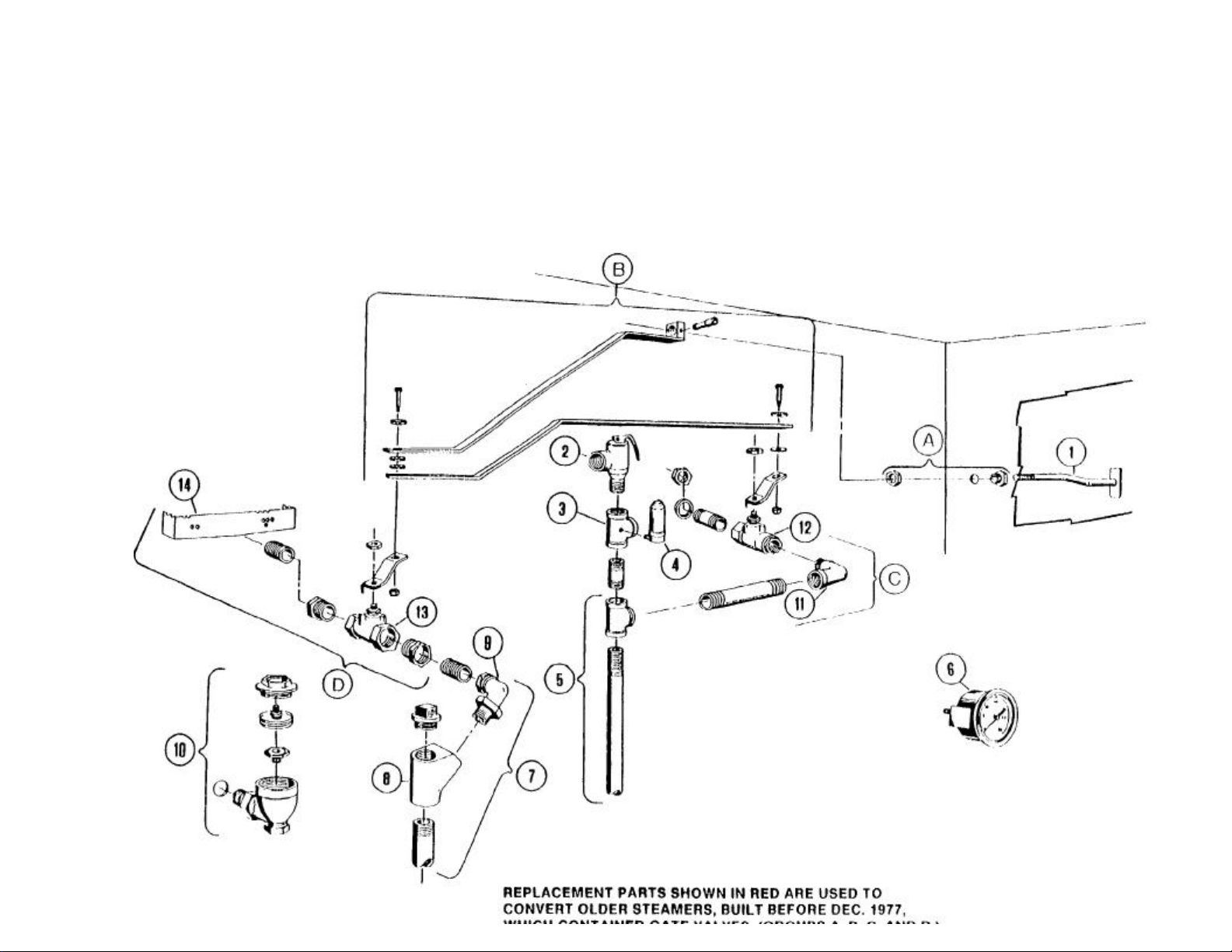
MECHANICAL COMPARTMENT CONTROLS
MODEL K PRESSURE STEAMERS-
DEC. 1977 THRU PRESENT

MECHANICAL COMPARTMENT CONTROLS MODEL K PRESSURE
STEAMERS-DEC. 1977 THRU PRESENT
REFERENCE PART
NUMBER NUMBER DESCRIPTION
1 40650 Pull Rod Handle
2 22130 Valve, Safely, 8 psi
3 70411 Tee, Special 3/4"
4 22140 Air Vent
5 42270 Inlet Manifold Ass'y.—2-Compl.—Mech. "K", Less Valves
42279 Inlet Manifold Ass'y.—3-Compl.—Mech. "K", Less Valves
6 07173 Gauge, Pressure, Rear Mount, 0 30 psi, 2 1/2"
07168 Gauge, Pressure, Rear Mount, 0-30 psi, 2"
7 42290 Exhaust Manifold Ass'y.—2-Compl., Model "K", Less Valves
42291 Exhaust Manifold Ass'y—3-Compl,, Model "K", Less Valves
8 02146 "Y" Bend
9 05263 Ell, 3/4" Radiator Union
10 20551 Thermostatic Trap—Plain End
11 05252 Ell, 1/2" Street
12 22212 Valve, 1/2 Ball, Inlet Steam
13 22213 Valve, 1" Bullerlly, Exhaust Steam
14 41100 Drain Cover Screen (Before 7/17/85)
69333 Drain Cover Screen (After 7/18/85)
A 43765 Bushing Ass'y.
B 40677 Linkage Ass'y., Model "K"
C 42670 Conversion Kit, Inlet Valve—'K" Mech., Includes:
1/2" Inlet Steam Valve, 1/2" Street Elbow, 1/2 x 4" NIppIe, 1/2" x 2 1/4" Special
Nipple, (2) Locknuts, (2) Sealing Washers
D 40710 Conversion Kit, Exhaust Valve, Includes:
1" Exhaust Steam Valve, (2) 1" x 3/4" Bushings, 3/4" Close Nipple, Drain Cover
Screen
NOTE: FOR SAFETY PURPOSES, DRAIN SCREEN COVER MUST BE IN PLACE WHEN OPERATING EQUIPMENT.
AUTOMATIC COMPARTMENT CONTROLS
MODEL K PRESSURE STEAMERS-
DEC. 1977 THRU PRESENT

AUTOMATIC COMPARTMENT CONTROLS
MODEL K PRESSURE STEAMERS — DEC. 1977 THROUGH PRESENT
1 40650
Pull Rod Handle
2 22130
Valve, Safety,
8
PSI 3 70411
Tee, Spe
cial 3/4" 4
22140
Air Vent
5
42298
Inlet Manifold Ass'y.
—2-
Compl
—
Auto "K", Less Valves
42299
Inlet Manifold Ass'y.
— 3-
Compt.
—
Auto "K", Less Valves
6
22115
Valve, 1/2" Steam Inlet Solenoid
7
03278
Valve, Steam By
-
Pass 8 42290
Exhaust Manifold Ass'
y.— 2-Compl,, Model "K", Less Valves
42291
Exhaust Manifold Ass'y
—3-
Compl., Model "K", Less Valves
9
43764
"Y" Bend
—
with 1/4" Tapped Hole
10
05263
Ell, 3/4" Radiator Union
11
20551
Thermostatic Trap
—
Plain End
12
22199
3/4
Solenoid Valve, Auto Exhaus
t,
115
Volt, For Use With
40518
Timer
22185
1/4" Solenoid Valve, Auto Exhaust,
115
Volt, For Use With
40540
Timer
13
07172
Gauge, Pressure, Bottom Mount,
0-30
PSI 14 40518
Timer,
60
Min, Mechanical (Mfg. # 70000)
15
19977
Switch
-
SPST 16 12
161 Signal Light,
1"
12169
Signal Light, 1
/2 17 07173
Pressure Gauge, Rear Mount,
0-30
psi, 2 1/2"
07168
Pressure Gauge, Rear Mount,
0-30
psi,
2" 18 41350
Buzzer
19
40540
Timer,
105
Min, (Mfg.
601) 20 22212
Valve, 1/2" Ball, Inlet Steam
21
22213
Valve,
1"
Butterlly, Exhaust Steam
22
41100
Drain Cover Screen (Before
7/17/85)
69333
Drain Cover Screen (After
7/18/85)
A
43765
Bushing Ass'y.,
B
40677
Linkage Ass'y., Model "K"
C
40711
Conversion Kit, Inlet Valve
-
"K" Auto, Includes:
1/2"
Inl
et Steam Valve,
3/8" Tube Ftng,
3/8"— 90°
Tube Ftng.,
(2)
1/2" Close Nipples,
1/2" x 2 1/4" Special Nipple 1/2 x
3/8" x 1/2 Tee,
3/8" x
6"
Tube,
(2)
Lock
-
nuts,
(2)
Sealing Washers.
D
40710
Conversion Kit, Exhaust Valve, Includes:
1" Exhaust
Steam Valve,
(2) 1"
x 3/4" Bushings, 3
/4
Close Nipple,
Drain Cover Screen.
REFERENCE
NUMBER
PART NUMBER DESCRIPTION
NOTE: FOR SAFETY PURPOSES, DRAIN SCREEN COVER MUST BE IN PLACE WHEN OPERATING EQUIPMENT
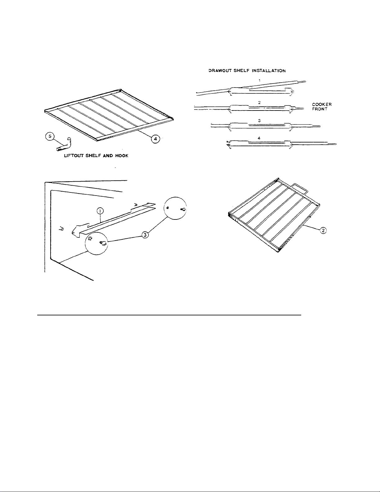
INTERMEDIATE DRAWOUT & LIFTOUT SHELF MODELS
1 • 19500
Angle Slide, Draw
-
Out Shelf, Model B, Right (Not Available)
• 19502
Angle Slide, Draw
-
Out Shelf Model B, Left (Not Availab
le) *19501
Angle Slide, Draw
-
Out Shelf, Model F, Right (Not Available)
•
19503
Angle Slide, Draw
-
Out Shelf, Model F, Left (Not Available)
2
42183
Draw-Out Intermediate Shelf, Model B
42814
Draw-Out Intermediate Shelf, Model F, J,
& K 3
43737
Fast
ener Assembly,
2
Per Slide, Includes
19216
Screw and
23109
Lockwasher
4
42180
Lift-Out Shelf, Model B
42181
Lift-Out Shelf, Model F
& K 5
08440
Lift-Out Shelf Hook,
4
Required Per Shelf
B, F, J, AND K PRESSURE STEAMERS
REFERENCE
NUMBER
PART NUMBER DESCRIPTION
Substitute: 4 ea. — 08440 Hooks
1 ea. — 42181 Shelf
CLEVELAND RANGE, INC., 1333 EAST 179th ST., CLEVELAND, OHIO 44110
Manufacturer reserves right of design improvement or modification, as warranted.
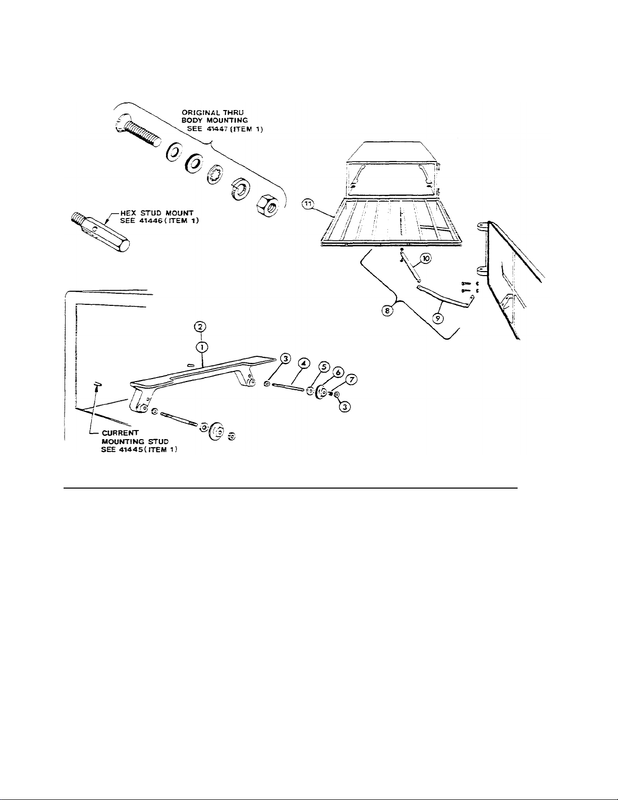
AUTO SHELF ASSEMBLY MODELS B & F
1 41445
Angle Slide Ass'y With Rollers, Models B
&
F, Includes
2
Weld Studs
19915
(Current, Since
1968)
(Shown)
41446
Angle Slide Ass'y With Rollers. Mod
els B & F, Includes
2
Hex Mount
ing Studs
19924
41447
Angle Slide Ass'y With Rollers, Models B
&
F, Includes Original Style
Body Mounting Bolt
&
Washers, etc.
2
01250
Angle Casting, Machined, Welded Stud, Models B
& F 01251
Angle Casting,
Machined. Hex Stud, Models B
& F 01252
Angle Casting, Machined. Bolted Stud, Models B
& P 3
14629
Lockout
4
19900
Roller Stud
5
23133
Washer
6
18720
Roller
7
19572
Roller Spring
8
43800
Shelf Arm
&
Connecting Rod Ass'y, Model B
43801
Shelf Ann
&
Connecting Rod Ass'y, Model F (Shown)
9
51002
Sliding Shelf Arm, Model B
51004
Sliding Shelf Arm, Model F (Shown)
10
42190
Connecting Rod, Model B
42191
Connecting Rod, Model F (Shown)
11
42185
Auto Sliding Shelf. Model B
42186
Auto Sliding
Shelf, Model F (Shown)
PRESSURE STEAMERS
REFERENCE
NUMBER
PART NUMBER DESCRIPTION
CLEVELAND RANGE, INC., 1333 EAST 179th ST., CLEVELAND, OHIO 44110
Manufacturer reserves right of design improvement or modification, as warranted.
 Loading...