

Page 1
Operators Manual
Installation, Operation & Service
Gas Floor Model Vertical Mixer Kettles
MODELS:
MKGL-40-T
MKGL-60-T
MKGL-80-T
MKGL-100-T
MKGL-40-T
SE55362 Rev. 5
1333 East 179th St., Cleveland, Ohio, U.S.A. 44110
Phone: (216) 481-4900 Fax: (216) 481-3782
Visit our web site at www.clevelandrange.com
d
Enodis
For units built prior to July 2010
™
Clev elan
Page 2
FOR THE USER
WARNING: Improper installation,
adjustment, alteration, service or
maintenance can cause property
damage, injury or death. Read the
installation and operating
instructions thoroughly before
installing or servicing this
equipment.
FOR YOUR SAFETY
DO NOT STORE OR USE GASOLINE
OR ANY OTHER
FLAMMABLE LIQUIDS AND
VAPOURS IN THE VICINITY
OF THIS OR ANY OTHER
APPLIANCE.
IMPORTANT!
ENSURE KETTLE IS AT ROOM TEMPERATURE AND
PRESSURE GAUGE IS SHOWING ZERO OR LESS PRESSURE
PRIOR TO REMOVING ANY FITTINGS.
.
IMPORTANT
The following points are to insure the safe installation and operation of this equipment:
• Insure all gas and electrical supplies match rating plate and electrical stickers.
• Observe all clearance requirements.
• Disconnect the electrical power supply to the appliance before cleaning or servicing unit.
• All service must be performed by a qualified Cleveland Range Technician.
• Do not obstruct the flow of combustion and ventilation air.
The installation and connection must comply with current local codes, or in the absence of local codes, with
CAN/CGA-B149.1 and .2 installation code or with the national fuel gas code, ANSI Z223.1-L988.
Post in a prominent location, instructions to be followed in the event the user smells gas. This information shall
be obtained by consulting your local gas supplier.
The appliance and its individual shut off valve must be disconnected from the gas supply piping system during
any pressure testing of that system at test pressures in excess of 1/2 psig. (3.45 kpa).
The appliance must be isolated from the gas supply piping system by closing its individual manual shut off
valve during any pressure testing of the gas supply piping system at test pressures equal to or less than 1/2
psig. (3.45 kpa).
RETAIN THIS MANUAL FOR YOUR REFERENCE.
Page 3
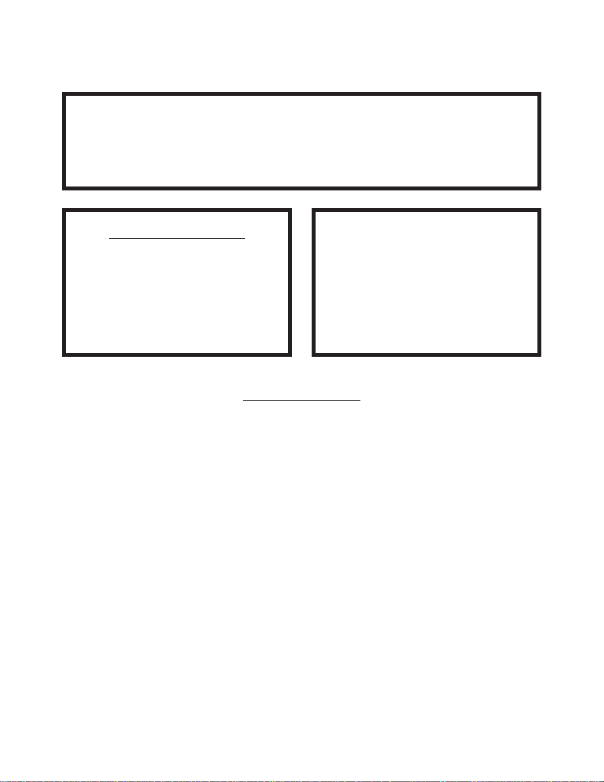
For your safety
DANGER
Keep clear of pressure
relief discharge.
IMPORTANT
Inspect unit daily for
proper operation.
CAUTION
Surfaces may be
extremely hot! Use
protective equipment.
Keep hands away from
moving parts and pinch points.
Do not fill kettle above
recommended level
marked on outside of kettle.
Wear protective equipment
when discharging hot product.
Do not lean on or place
objects on kettle lip.
SERVICING
Shut off power at main
fuse disconnect prior
to servicing.
GAS APPLIANCES
Do not attempt to operate
this appliance during a
power failure.
Stand clear of product
discharge path when
discharging hot product.
Ensure kettle is at room
0
temperature and pressure
gauge is showing zero or less
prior to removing any fittings.
Keep appliance and area free
and clear of combustibles.
Page 4

INSPECTION
Before unpacking visually inspect the unit for evidence
of damage during shipping.
If damage is noticed, do not unpack the unit, follow
shipping damage instructions.
SHIPPING DAMAGE
INSTRUCTIONS
If shipping damage to the unit is discovered or
suspected, observe the following guidelines in
preparing a shipping damage claim.
1. Write down a description of the damage or the
reason for suspecting damage as soon as it is
discovered. This will help in filling out the claim
forms later.
2. As soon as damage is discovered or suspected,
notify the carrier that delivered the shipment.
3. Arrange for the carrier's representative to examine
the damage.
4. Fill out all carrier claims forms and have the
examining carrier sign and date each form.
GENERAL
Installation of the kettle must be accomplished by
qualified installation personnel working to all applicable
local and national codes. Improper installation of
product could cause injury or damage.
This equipment is built to comply with applicable
standards for manufacturers. Included among those
approval agencies are: UL, A.G.A., NSF, ASME/N.Bd.,
CSA, CGA, ETL, and others. Many local codes exist,
and it is the responsibility of the owner/installer to
comply with these codes.
Observe all clearance requirements to provide proper
make-up air flow. Do not obstruct the flow of combustion
and ventilation air. Check rating plate to ensure that
kettle has been equipped to operate with the type of
gas available at the installation.
VENTILATION
Gas fired kettles are only to be installed under a
ventilation hood in a room which has provisions for
adequate make up air. Further information can be
obtained by referring to the U.S.A. National Fire
Protection Associations NFPA96 regulations. These
standards have also been adopted by the National
Building Code in Canada.
CLEARANCE REQUIREMENTS
This unit must be installed in accordance with the
clearances shown on the rating label which is adhered
to the unit.
FOR YOUR SAFETY. Keep the appliance area free and
clear of combustible materials.
GAS
ENSURE THE GAS SUPPLY MATCHES THE
KETTLE'S REQUIREMENTS AS STATED ON THE
RATING PLATE.
It is recommended that a sediment trap (drip leg) be
installed in the gas supply line. If the gas pressure
exceeds 14” water column, a pressure regulator must
be installed, to provide a maximum of 14” water column
gas pressure to the gas control valve.
Connect the gas line to the manual valve located at the
rear of the control box.
Installation must be in accordance with local codes
and/or the National Fuel Gas Code ANSI Z223.1 Latest
Edition (USA) or the latest Installation Codes for Gas
Burning Appliances and Equipment CAN/ CGA B149.1
and CAN/ CGA B149.2 (Canada). Use a gas pipe joint
compound which is resistant to L.P. gas. Test all pipe
joints for leaks with soap and water solution. Ensure that
the gas pressure regulator is set for the manifold
pressure indicated on the gas rating plate.
The appliance and its individual shut-off valve must be
disconnected from the gas supply piping system during
any pressure testing of that system at test pressures in
excess of 1/2 psi (3.45 kPa). The appliance must be
isolated from the gas supply piping system by closing
its individual manual shut-off valve during any pressure
testing of the gas supply piping system at test
pressures equal to or less than 1/2 psi (3.45 kPa).
WATER
The sealed jacket of the gas-fired kettle is precharged
with the correct amount of a water-based formula, and
therefore, no water connection is required to the kettle
jacket. The kettle can be equipped with optional hot and
cold water taps, the taps require 1/2" copper tubing as
supply lines.
CLEANING
After installation the kettle must be thoroughly cleaned
and sanitized prior to cooking.
INSTALLATION
Page 5
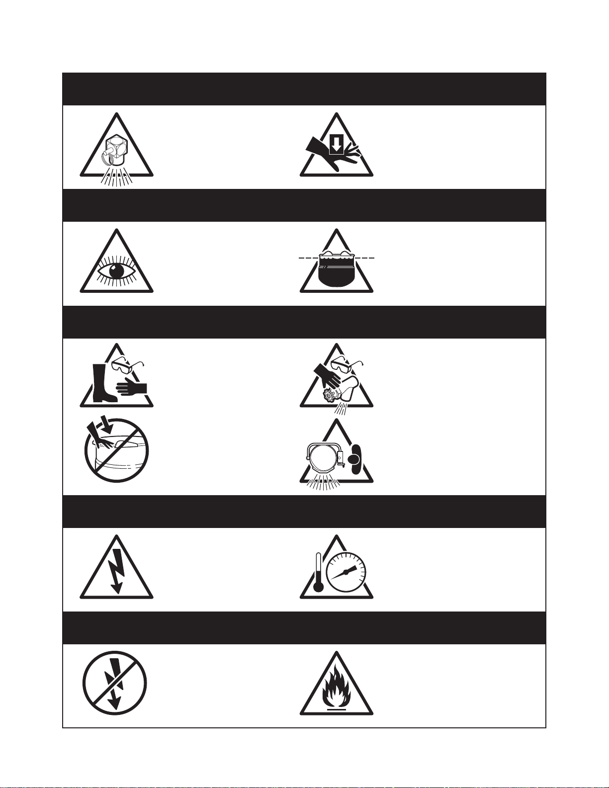
MOVING UNIT
1. While still on skid, move unit as close to final
installation position as possible.
2. Prepare unit for lifting as shown in diagram.
3. Lift gently with a forklift or jacks and remove skid.
4. Lower gently to ground and remove forklift and
blocking.
5. If unit has to be re-positioned, slide gently. Do not
twist or push one side of unit excessively and
cause binding on trunnions.
Shim as
required
to make
level with
center
console
(front
and back)
4"x4" or larger
(front and back)
Forklift tongsSkid
Flanged feet
Jack
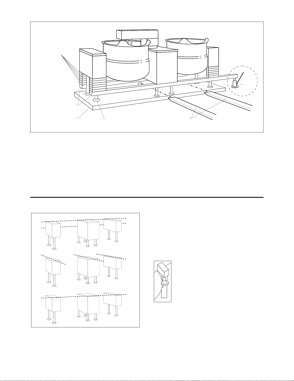
LEVELING
Recommended Leveling Procedure
1. With straight-edge, line the backs of the consoles
up with each other (dotted line A)
.
2.
Level and straight-edge backs of consoles
(dotted line
B)
. Adjustments are made by turning flanges on back
feet only.
3.
Level consoles individually from front to back (dotted
lines C). Adjustments are made by turning flanges on
front feet only.
4. Re-check that the back is level (dotted line B) and
then the front (dotted line D). Adjust if necessary.
5. Check that mixer bridge is level and
guide pins lock smoothly without binding. If
not repeat steps 1 through 4.
Guide Pins
NOTE: See Operating Instructions before operating
unit.
6. Make electrical connections (see electrical service
connections) and test mixer bridge as follows:
⇒ A/ Raise mixer bridge.
⇒ B/ Swing bridge out over centre console.
B
A
C
D
B
A
C
D
C
C
C
C
Recommended Installation Procedure
Note: Instructions reflect a more complicated twin mixer kettle - process for single mixer kettles is the same.
Page 6

⇒ C/ Swing bridge to the left as far as possible.
⇒ D/ Lower bridge.
⇒ E/ Bridge pins should enter pin hole on kettle
perfectly, If not return to step 1 and repeat leveling
steps.
⇒ F/ Raise bridge and swing to far right (for twin
mixers only).
⇒ G/ Repeat
steps D and
E (for twin
mixers only).
7.
Once
positioned
and leveled,
permanently
secure the
kettle's flanged feet to the floor using 5/16 inch
stainless steel lag bolts and floor anchors (supplied
by the installer). Secure each of the flanged feet with
one bolt in each hole. Seal joints of flanged feet with
a silicone sealant.
ELECTRICAL SERVICE
CONNECTIONS
ENSURE THE ELECTRICAL SUPPLY MATCHES THE
KETTLE'S REQUIREMENTS AS STATED ON THE
RATING LABEL.
Install in accordance with local codes and/or the National
Electric Code ANSI/NFPA No 70-1981 (USA) or the
Canadian Electric Code CSA Standard C22.1 (Canada). A
separate fused disconnect switch must be supplied and
installed. The kettle must be electrically grounded by the
installer.
The electric supply must match the power requirements
specified on the kettle's rating plate. The copper wiring
must be adequate to carry the required current at the rated
voltage.
1. Ensure main power is turned off before connecting
wires.
2. Remove the screws at the rear of the mixer console
cover, and remove the cover. A wiring diagram is
affixed to the underside of the console cover.
3. Feed permanent copper wiring 18" through the cutout in the bottom of the console. Connect
wiring in
junction box in the bottom of the console.
4. Turn main power back on.
5. Check for correct rotation of electric motor (access
by removing top front cover on center console). If
rotation is incorrect, disconnect main power and
reverse any two of the three live lines.
6. Replace the console cover and secure it with
screws.
COMPRESSED AIR CONNECTION
Mixer Kettles with an air activated discharge valve require a
minimum of 90 PSI to operate correctly.
If the unit is also supplying air to a Metering Filling Station then
a pressure of 100 PSI at a minimum volume of 25 CFM is
required.
The air supplied to the mixer should be clean and dry. No oil
should be added to the supply air. We recommend the
compressed air system be equipped with a drier, filter, and
automatic water dump on the air compressor receiver tank. If
the distance between the tank and the unit is less than 100
feet then a minimum line size of 3/4" is required. A distance of
100 to 300 feet requires a minimum 1" line.
7/16"Ø, 3 HOLES
ON 3 1/8" (80mm) B.C.D.
FLANGED FOOT DETAIL
(REAR LEGS ONLY)
120 120
4 7/8" (124mm)
Page 7

INSTALLATION
1. Visual Examine unit for scratches, dents, or other defects.
2. Visual Check flanged feet all have bolts holding them.
3. General Check all accessible wiring, mechanical and plumbing connections by hand for secure,
tight and satisfactory assembly. Remove all paper.
4. Level Check unit has been leveled and squared correctly.
KETTLE
Although the kettle has been thoroughly tested before leaving the factory, the installer is responsible for ensuring the
proper operation of kettle once installed.
DO NOT ATTEMPT TO OPERATE THIS APPLIANCE DURING A POWER FAILURE.
KEEP APPLIANCE AND AREA FREE AND CLEAR OF COMBUSTIBLES.
1. Before turning the kettle on, read the vacuum/pressure gauge. The gauge's needle should be in the green zone.
If the needle is in the "VENT AIR" zone, follow air venting procedure.
2. Supply power to the kettle by placing the fused disconnect switch to the "ON" position.
3. Turn on main gas supply to unit. Open the kettle's shut-off valve (located at back of console).
4. Turn the temperature control knob to "1`" (Min.). The green LED light should remain lit, indicating the burner is lit, until the
set temperature is reached. Then the green light will cycle on and off, indicating the burner is cycling on and off to
maintain temperature.
5. Tilt the kettle forward. After a few seconds the red "LOW WATER" light should be lit when the kettle is in a tilted
position. This light indicates that the burner has automatically been shut off by the kettle's safety circuit. This is a
normal condition when the kettle is in a tilted position.
6. Raise the kettle to the upright position. The red "LOW WATER" light should go out when the kettle is upright.
7. Turn the temperature control knob to "10" (Max.) and allow the kettle to preheat. The green light should remain on
until the set temperature is reached. Then the green light will cycle ON and OFF, indicating the burner is cycling
ON and OFF to maintain temperature
MIXER
1. Raise Bridge If bridge does not raise then check motor rotation. Bridge should not raise until speed control
is turned to minimum and then adjusted back up.
2. Swing Bridge Bridge when fully raised should swing without hitting any object, i.e. control housing,
kettle lip. Check that hydraulic hoses are not being pinched by stops on swivel assembly.
3. Tilt Kettle Kettle tilts smoothly both down and back up. If power tilt, check that micro switches are
adjusted properly (kettle is level in upright position and drains fully when tilted) and are
not being crushed by gear.
4. Lower Bridge Raise bridge. Switch to mix. Turn speed control to zero to reset micro switch then set
speed control to number four. Check that unit does not begin to mix until bridge has
lowered part way into the kettle. Check that mixer bridge pin lowers into pin hole correctly
5. Speed Control - Main agitator arm not rotating when set at "0" but will start to move slowly on
Main "1" . Speed control makes positive contact with micro switch.
6. Speed Control - Set main speed control to five. Adjust secondary control from
Secondary minimum to maximum. Look for considerable speed variance.
7. Water Faucets Turn on hot water faucet. Turn off and check for leaks in piping and drips from
faucet spout. Repeat above with cold water faucet.
8. Product Discharge Add water to kettle. Check for leaks from valve. Open and close valve a few times
Valve and check for leaks again.
QUALITY ASSURANCE CHECKS
Page 8
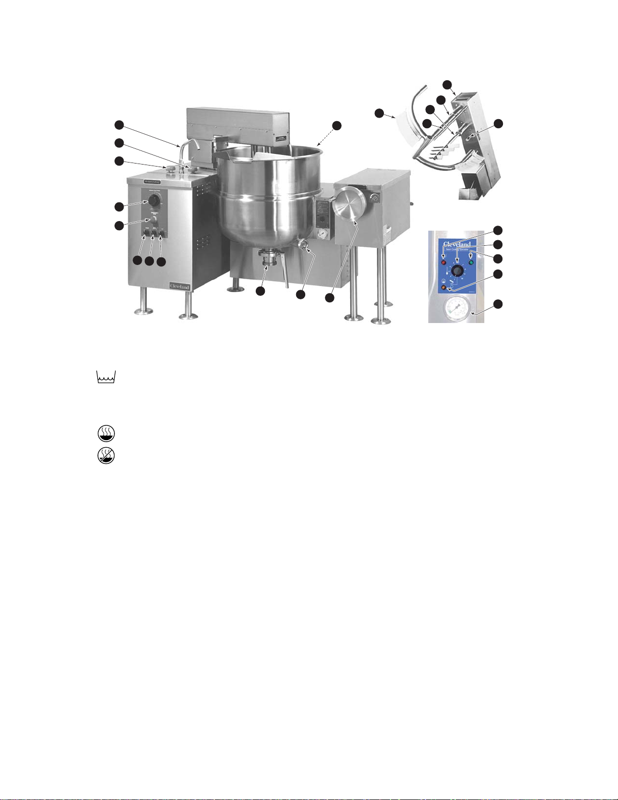
OPERATING INSTRUCTIONS
3
4
5
2
1
7
8
9
12
13
14
6
10
11
17
16
15
20
21
23
19
18
22
ITEM # DESCRIPTION FUNCTION
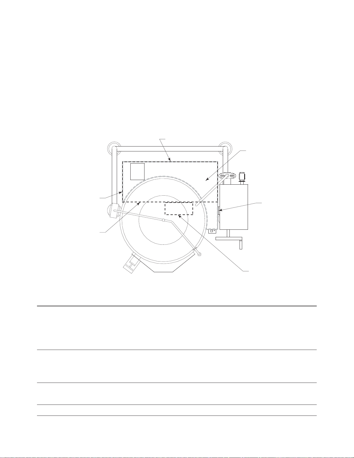
1. Low Water Indicator Light (Red) When lit, indicates that the kettle is low on water and will not operate
in this condition. This will also light when the kettle is tilted.
2. On-Off Switch/ Turns kettle ON/OFF and allows the operator to adjust the kettle
Solid State temperature in increments from 1 (Min.) to 10 (Max.).
Temperature Control
3. Heat Indicator Light (Green) When lit, indicates that the kettle's burner is on.
Cycles ON-OFF with burner.
4. Ignition Failure Indicator Light Indicates failure of heating system to ignite.
(Amber) (Used prior to July 2004)
5. Vacuum/Pressure Gauge Indicate steam pressure in PSI inside steam jacket as well as
vacuum in inches of mercury.
6. Pressure Relief Valve This valve is used to vent the kettle and in the unlikely event there is
(not shown) an excess steam build-up in the jacket, this valve opens
automatically to relieve this pressure.
7. Water Level Sight Glass Displays water level in steam jacket.
8. Tilt Wheel Used for tilting the kettle on hand tilt models. In power tilt models
there is a toggle switch in same location.
9. Butterfly Valve Used for draining product or wash water from kettle.
10. Mixer Speed Control Controls speed of agitators and mixer bridge lift mode.
11. Emergency Stop Stops hydraulic system.
12. Main Power Switch Power switch for unit.
13. Mix/Lift Switch Sets hydraulics to mix or lift mode.
14. Up/Down Switch When unit is in lift mode, bridge can be raised or lowered with this switch.
15. Faucet Spout Delivers water to the kettle.
16. Cold Water Valve Turns on cold water.
17. Hot Water Valve Turns on hot water.
18. Mixer Bridge Encloses agitator motors.
19. Main Agitator Arm Provides most of the product movement.
20. Secondary Arm Provides reverse agitation and product lift in kettle.
21. Scraper Blades Scrapes the side of the kettle and moves product away.
22. Secondary Speed Control Controls speed of secondary agitator arm.
23. Temperature Probe Probe holds temperature sensors for controller.
Operating Controls & Indicators
Page 9
OPERATING THE KETTLE
Do not attempt to operate this
appliance during a power failure.
Keep appliance and area free and
clear of combustibles.
Do not lean on or place objects on kettle lip.
Serious injury could result if kettle tipped over,
spilling hot contents.
If you are cooking an egg or milk product,
do not pre-heat kettle.
Cooking
1. Before turning kettle on, read the Vacuum/Pressure
Gauge (5). The gauges needle should be in the
green zone. Once heated, the kettle's normal
maximum operating pressure is approximately 1012 psi while cooking a water base product.
2. Ensure that the electrical service to the kettle is
turned on at the fused disconnect switch.
Temperature Range Chart
3. Preheat the kettle by turning the ON/OFF
Switch/Solid State Temperature Control (2) to the
desired temperature setting (see above
"Temperature Range Chart"). The Heat Indicator
Light (Green) (3) will remain lit, indicating the
burner is on, until the temperature setting is
reached. When the green light goes off, the
burners are off, and preheating is complete.
NOTE: When cooking egg and milk products, the kettle
should not be preheated, as products of this nature
adhere to hot cooking surfaces. These types of food
should be placed in the kettle before heating is begun.
4. Place food product into the kettle. The green Heat
Indicator Light (3) will cycle on and off indicating
the burners are cycling on and off to maintain the
set temperature.
NOTE: Do not fill kettle above
recommended level marked on outside
of kettle.
NOTE: The red Low Water Indicator Light (1) should
not be lit when the kettle is in the upright position during
kettle operation. This light indicates that the burners
have been automatically shut off by the kettle's safety
circuit. It is, however, normal for the red light to come on
when the kettle is in a tilted position.
5. When cooking is completed turn On/Off
Switch/Solid State Temperature Control (2) to the
"OFF' position.
NOTE: A five minute complete shut-of period is
required before relighting.
6. Pour the contents of the kettle into an appropriate
container by tilting the kettle forward. Care should
be taken to pour slowly enough to avoid splashing
off the product.
NOTE: As with cleaning food soil from any cookware,
an important part of kettle cleaning is to prevent food
from drying on. For this reason, cleaning should be
completed immediately after cooked foods are
removed.
Approximate Boiling Times
The accompanying chart shows approximate times
required for gas kettles of various capacities to boil
water with the lid open. The ON/OFF Switch/Solid State
Temperature Control (2) must be set at “10” throughout
the heat-up period. Water will boil about 1/3 faster if the
kettle is filled only to the outer steam jacket’s welded
seam resulting in a kettle filled to 2/3 capacity.
Approximate Boiling Times
Kettle Capacity Minutes
40 gallon 35
60 gallon 47
80 gallon 60
100 gallon 75
Temperature Approximate
Control Product Temperature
Setting °F °C
1. 120 49
2. 135 57
3. 150 66
4. 165 74
5. 180 82
6. 195 91
7. 210 99
8. 225 107
9. 245 118
10. 265 130
NOTE: Certain combinations of ingredients will result in temperature variations.
!
Page 10
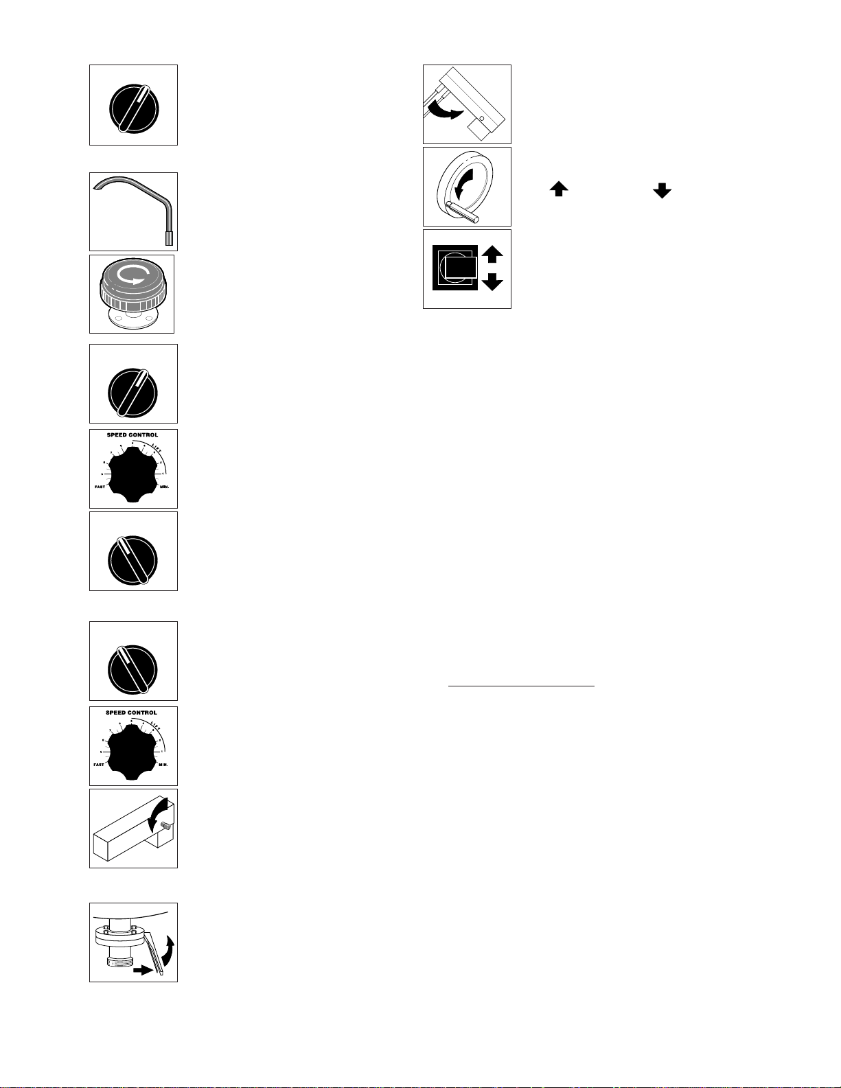
Discharge Valve
2. Push handle in and pull
upwards to open.
MIX LIFT
OFF
Mixing
1. Turn MIX/LIFT SWITCH (14) to
"MIX".
2. Turn MIXER SPEED
CONTROL (10) to "MIN" and
slowly adjust to desired
speed.
3. Adjust SECONDARY SPEED
CONTROL (22) to desired
speed.
UP DOWN
OFF
MIX LIFT
OFF
Lifting & Lowering
Bridge
WARNING- Insure FAUCET
SPOUT (15) is out of way before
raising or lowering bridge.
1. Turn MIX/LIFT SWITCH (13) to
"LIFT".
2. Turn MIXER SPEED
CONTROL (10) to "MIN"
and
back up to #5.
3. Turn and hold UP/DOWN
SWITCH (14) "UP" to raise or
"DOWN" to lower.
Adding Water
Manually
1. Locate FAUCET SPOUT (15)
over desired kettle.
2. Turn on HOT or COLD WATER
VALVES (16 or 17).
OFF ON
General Operation
1. Turn MAIN POWER SWITCH
(12) to "ON".
OPERATING SUGGESTIONS
Cleveland Range Mixer Kettles are simple and
safe to operate. The following tips will allow you to
maximize the use of your new mixer.
1.
Allow unit to preheat before addition of product to
kettle. However when cooking egg and milk
products, the kettle should NOT be preheated, as
products of this nature adhere to hot cooking
surfaces. These types of foods should be placed
in the kettle before heating is begun.
2. An important part of kettle cleaning is to
prevent foods from drying on. For this reason,
cleaning should be completed immediately
after cooked foods are removed.
3. If a mixer bridge is equipped with a
temperature probe for a controller or
thermometer, the probe must be submerged a
minimum of three inches
in the product for
accurate readings.
Safety
1. Close BUTTERFLY VALVE (9) before filling the
kettle.
2. When raising or lowering MIXER BRIDGE (18),
insure FAUCET SPOUT (15) is not in the way
of MAIN AGITATOR ARM (19) or damage to
spout will result.
3.
As a safety precaution the MIXER SPEED
CONTROL (10) must first be turned to zero
before unit will start to mix.
4. Always remember, like a cooking pot the
kettles become very hot when cooking. Avoid
contact with bare skin.
Tilting Kettle
1. Raise MIXER BRIDGE (18)
and swing to side.
2. For
manual tilt:
turn TILT
WHEEL (8).
3. For
power tilt:
turn switch
" " to raise, or " " to tilt.
WARNING- Do not tilt kettle
when mixer agitators are in kettle
bowl.
Page 11
CARE AND CLEANING
Cooking equipment must be cleaned regularly to
maintain its fast, efficient cooking performance and
to ensure its continued safe, reliable operation. The
best time to clean is shortly after each use (allow
unit to cool to a safe temperature).
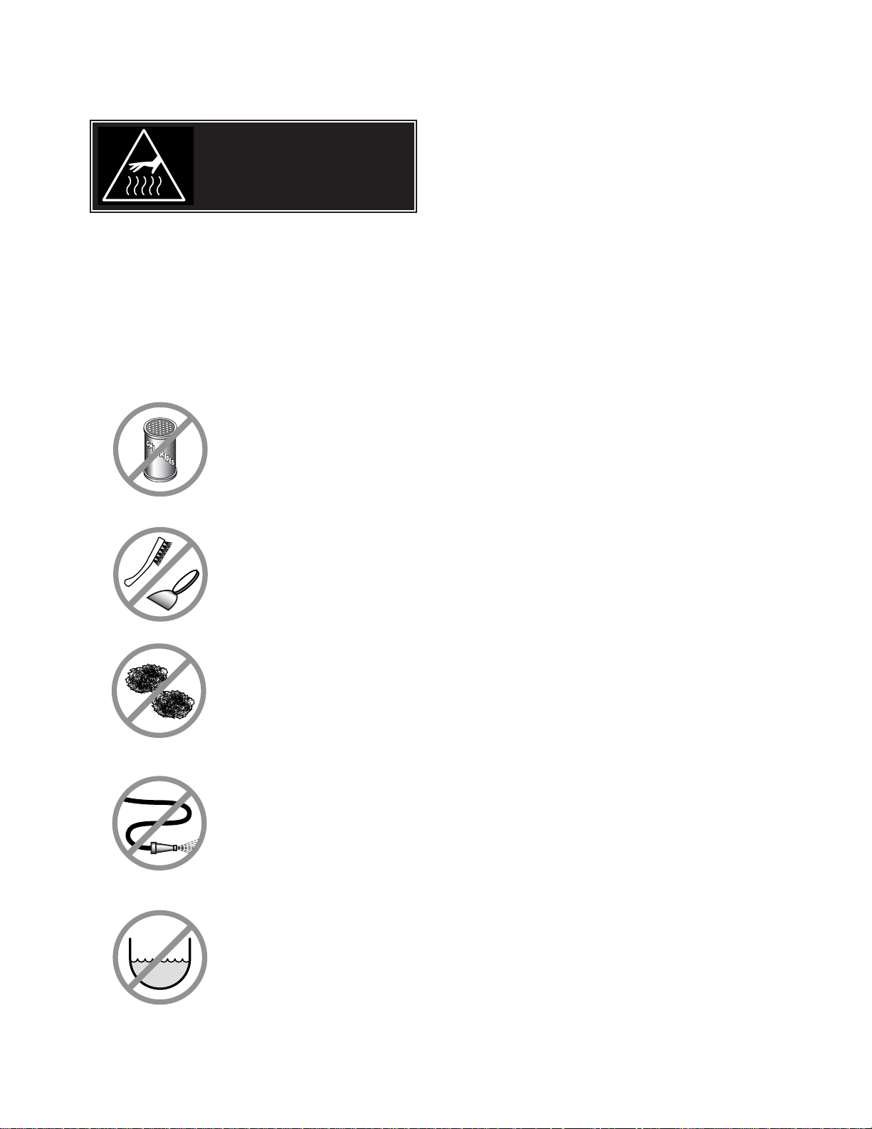
WARNINGS
➩ Do not use detergents or
cleansers that are chloride
based or contain quaternary
salt.
➩ Do not use a metal bristle
brush or scraper.
➩ Steel wool should never be
used for cleaning the stainless
steel.
➩ Unit should never be cleaned
with a high pressure spray
hose.
➩
Do not leave water sitting in unit
when not in use.
Stagnant
Water
High Pressure
Spray Hose
Chloride Cleaners
Steel Pads
Wire Brush &
CLEANING INSTRUCTIONS
CAUTION
SURFACES MAY
BE EXTREMELY HOT!
CLEANING INSTRUCTIONS
1. Turn unit off.
2. Remove drain screen (if applicable). Thoroughly
wash and rinse the screen either in a sink or a
dishwasher.
3. Prepare a warm water and mild detergent solution in
the unit.
4. Remove food soil using a nylon brush.
5. Loosen food which is stuck by allowing it to soak at
a low temperature setting.
6. Drain unit.
7. Rinse interior thoroughly.
8. If the unit is equipped with a Tangent Draw-Off
Valve, clean as follows:
a) Disassemble the draw-off valve first by turning
the valve knob counter-clockwise, then turning
the large hex nut counter-clockwise until the
valve stem is free of the valve body.
b) In a sink, wash and rinse the inside of the valve
body using a nylon brush.
c)
Use a nylon brush to clean tangent draw-off tube.
d) Rinse with fresh water.
e) Reassemble the draw-off valve by reversing the
procedure for disassembly. The valve's hex nut
should be hand tight only.
9. If the unit is equipped with a Butterfly Valve, clean
as follows:
a) Place valve in open position.
b) Wash using a warm water and mild detergent
solution.
c) Remove food deposits using a nylon brush.
d) Rinse with fresh water.
e) Leave valve open when unit is not in use.
10 . Using mild soapy water and a damp sponge, wash
the exterior, rinse, and dry.
NOTES
➩ For more difficult cleaning applications one of the
following can be used: alcohol, baking soda, vinegar,
or a solution of ammonia in water.
➩ Leave the cover off when the kettle is not in use.
➩ For more detailed instructions refer to the Nafem
Stainless Steel Equipment Care and Cleaning manual
(supplied with unit).
Page 12

STAINLESS STEEL EQUIPMENT CARE AND CLEANING
(Suppied courtesy of Nafem. For more information visit their web site at www.nafem.org)
Contrary to popular belief, stainless steels ARE susceptible to rusting.
Corrosion on metals is everywhere. It is recognized quickly on iron and
steel as unsightly yellow/orange rust. Such metals are called “active”
because they actively corrode in a natural environment when their atoms
combine with oxygen to form rust.
Stainless steels are passive metals because they contain other metals, like
chromium, nickel and manganese that stabilize the atoms. 400 series
stainless steels are called ferritic, contain chromium, and are magnetic;
300 series stainless steels are called austenitic, contain chromium and
nickel; and 200 series stainless, also austenitic, contains manganese,
nitrogen and carbon. Austenitic types of stainless are not magnetic, and
generally provide greater resistance to corrosion than ferritic types.
With 12-30 percent chromium, an invisible passive film covers the steel’s
surface acting as a shield against corrosion. As long as the film is intact
and not broken or contaminated, the metal is passive and stain-less. If the
passive film of stainless steel has been broken, equipment starts to
corrode. At its end, it rusts.
Enemies of Stainless Steel
There are three basic things which can break down stainless steel’s
passivity layer and allow corrosion to occur.
1. Mechanical abrasion
2. Deposits and water
3. Chlorides
Mechanical abrasion means those things that will scratch a steel surface.
Steel pads, wire brushes and scrapers are prime examples.
Water comes out of the faucet in varying degrees of hardness. Depending
on what part of the country you live in, you may have hard or soft water.
Hard water may leave spots, and when heated leave deposits behind that
if left to sit, will break down the passive layer and rust stainless steel. Other
deposits from food preparation and service must be properly removed.
Chlorides are found nearly everywhere. They are in water, food and table
salt. One of the worst chloride perpetrators can come from household and
industrial cleaners.
So what does all this mean? Don’t Despair!
Here are a few steps that can help prevent stainless steel rust.
1.
Use the proper tools.
When cleaning stainless steel products, use non-abrasive tools. Soft
cloths and plastic scouring pads will not harm steel’s passive layer.
Stainless steel pads also can be used but the scrubbing motion must
be in the direction of the manufacturers’ polishing marks.
2.
Clean with the polish lines.
Some stainless steel comes with visible polishing lines or “grain.”
When visible lines are present, always scrub in a motion parallel to the
lines. When the grain cannot be seen, play it safe and use a soft cloth
or plastic scouring pad.
3.
Use alkaline, alkaline chlorinated or non-chloride containing cleaners.
While many traditional cleaners are loaded with chlorides, the industry
is providing an ever-increasing choice of non-chloride cleaners. If you
are not sure of chloride content in the cleaner used, contact your cleaner
supplier. If your present cleaner contains chlorides, ask your supplier if
they have an alternative. Avoid cleaners containing quaternary salts; it
also can attack stainless steel and cause pitting and rusting.
4.
Treat your water.
Though this is not always practical, softening hard water can do much
to reduce deposits. There are certain filters that can be installed to
remove distasteful and corrosive elements. To insure proper water
treatment, call a treatment specialist.
5.
Keep your food equipment clean.
Use alkaline, alkaline chlorinated or non-chloride cleaners at
recommended strength. Clean frequently to avoid build-up of hard,
stubborn stains. If you boil water in stainless steel equipment,
remember the single most likely cause of damage is chlorides in the
water. Heating cleaners that contain chlorides have a similar effect.
6.
Rinse, rinse, rinse.
If chlorinated cleaners are used, rinse and wipe equipment and
supplies dry immediately. The sooner you wipe off standing water,
especially when it contains cleaning agents, the better. After wiping
equipment down, allow it to air dry; oxygen helps maintain the
stainless steel’s passivity film.
7.
Never use hydrochloric acid (muriatic acid) on stainless steel.
8.
Regularly restore/passivate stainless steel.
Recommended cleaners for specific situations
Job Cleaning Agent Comments
Routine cleaning Soap, ammonia, Apply with cloth or sponge
detergent, Medallion
Fingerprints & smears Arcal 20, Lac-O-Nu Provides barrier film
Ecoshine
Stubborn stains & Cameo, Talc, Zud, Rub in direction of polish lines
discoloration First Impression
Grease & fatty acids, Easy-off, De-Grease Excellent removal on all finishes
blood, burnt-on-foods It Oven Aid
Grease & oil Any good Apply with sponge or cloth
commercial detergent
Restoration/Passivation Benefit, Super Sheen
Review
1. Stainless steels rust when passivity (film-shield) breaks down as a
result of scrapes, scratches, deposits and chlorides.
2. Stainless steel rust starts with pits and cracks.
3. Use the proper tools. Do not use steel pads, wire brushes or scrapers
to clean stainless steel.
4. Use non-chlorinated cleaners at recommended concentrations. Use
only chloride- free cleaners.
5. Soften your water. Use filters and softeners whenever possible.
6. Wipe off cleaning agent(s) and standing water as soon as possible.
Prolonged contact causes eventual problems.
To learn more about chloride-stress corrosion and how to prevent it,
contact the equipment manufacturer or cleaning materials supplier.
Developed by Packer Engineering, Naperville, Ill., an independent testing
laboratory.
Page 13
WRAP COVERS
KETTLE TOP FRONT LEFT SIDE RIGHT SIDE BACK
KGL-40 KE01479-X KE53483-4 KE54253-X KE01432-X KE02186-1
KGL-60 KE01479-1 KE53483-5 KE54253-1 KE01432-1 KE02186-2
KGL-80 KE01479-2 KE53483-6 KE54253-2 KE01432-2 KE02186-3
KGL-100 KE01479-3 KE53483-7 KE54253-3 KE01432-3 KE02186-4
KGL-40-T KE01479-X KE53483-X KE54253-X KE01432-X KE02186-1
KGL-60-T KE01479-1
KE53483-1 KE54253-1 KE01432-1 KE02186-2
KGL-80-T KE01479-2 KE53483-2 KE54253-2 KE01432-2 KE02186-3
KGL-40-SH KE01479-4 KE53483-6 KE54253-2 KE01432-2 KE02186-3
KGL-60-SH KE01479-5 KE53483-7 KE54253-3 KE01432-3 KE02186-4
KGL-40-TSH KE01479-4 KE53483-2 KE54253-2 KE01432-2 KE02186-3
WARRANTY
Our Company supports a worldwide network of
Maintenance and Repair Centers. Contact your
nearest Maintenance and Repair Centre for
replacement parts, service, or information
regarding the proper maintenance and repair of
your cooking equipment
In order to preserve the various agency safety
certification (UL, NSF, ASME/Ntl. Bd., etc.), only
factory-supplied replacement parts should be
used. The use of other than factory supplied
replacement parts will void warranty.
SERVICE PARTS
BACK
TOP
LEFT SIDE
FRONT
RIGHT SIDE
TRANSFORMER
COVER & GASKET
Page 14

PRESSURE RELIEF
ASSEMBLY
ITEM NO. PART NO. DESCRIPTION QTY.
PRESSURE RELIEF VALVE ASSEMBLIES
1. KE01450 FOR ASME KETTLES (INCLUDES #2-6) 1
KE01450-1 FOR CE KETTLES (INCLUDES #2-6) 1
2. FA05049 MALE CONNECTOR, 1/2" PIPE - 1/4" TUBE 1
3. FI00151 STREET ELBOW, 90°, 1/2", BRASS 2
4. FI00178 TEE, 1/2" FPT, BRASS 1
SAFETY VALVES
5. KE54941-5 SAFETY VALVE, 50 PSI, 1/2" (NORTH AMERICA) 1
KE54941-31 SAFETY VALVE, 50 PSI, 1/2", (EUROPE) 1
6. KE54223 BLOW DOWN TUBE 1
7. KE54864 ACCESS PANEL 1
8. FA11518-4 THUMB SCREW, 10-32 X 1/2" L 1
2
3
54
6
8
7
Page 15
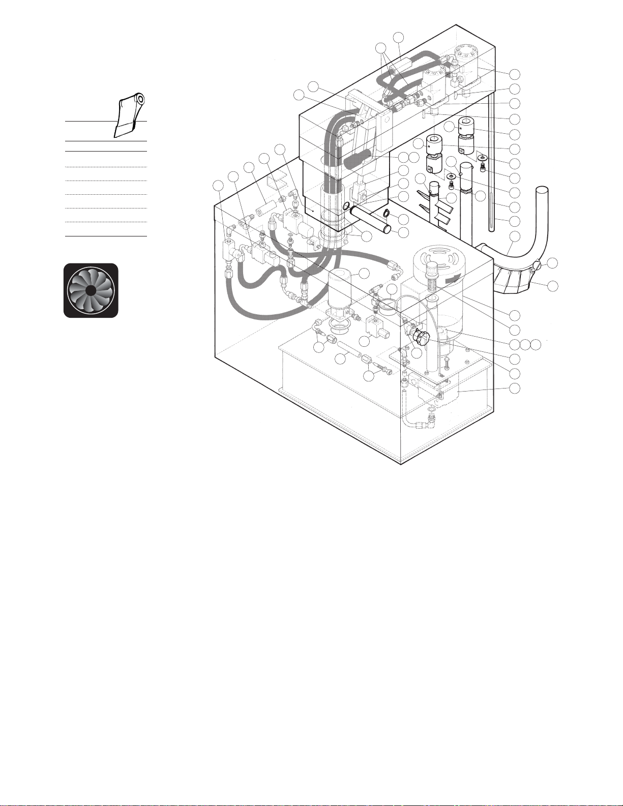
NOTE: For Hydraulic Hoses order
Part No. RT00505 and specify
length required
Cooling Fan:
Fan . . . . . . . . KE54860
Fan Cover . . . KE601236
Fan Guard . . . KE54861
KETTLE
SIZE
GALLONS QUANTITY
40 22
60 26
80 30
100 34
125 38
150 38
Scraper
Blades:
HYDRAULIC
COMPONENTS
ITEM NO. PART NO. DESCRIPTION QTY.
1. KE51607 Flow Control Valve . . . . . . . . . . . . . . . . . . . . . . . . . . . . . . . . . . . . . . . . . . . . . . . . . . . . . . . .2
2. KE54834-10 Solenoid Valve, 2 Way, 120 Volt . . . . . . . . . . . . . . . . . . . . . . . . . . . . . . . . . . . . . . . . . . . . .1
SE50224 Coil Only 120 Volt . . . . . . . . . . . . . . . . . . . . . . . . . . . . . . . . . . . . . . . . . . . . . . . . . . . . . . . .1
3. KE51608 Check Valve . . . . . . . . . . . . . . . . . . . . . . . . . . . . . . . . . . . . . . . . . . . . . . . . . . . . . . . . . . . .1
4. KE54834-11 Solenoid Valve, 3 Way, 120 Volt . . . . . . . . . . . . . . . . . . . . . . . . . . . . . . . . . . . . . . . . . . . . .1
SE50224 Coil Only 120 Volt . . . . . . . . . . . . . . . . . . . . . . . . . . . . . . . . . . . . . . . . . . . . . . . . . . . . . . . .1
5. KE51848 Jack . . . . . . . . . . . . . . . . . . . . . . . . . . . . . . . . . . . . . . . . . . . . . . . . . . . . . . . . . . . . . . . . . . .1
SE50241 Rod Gland Seal Kit . . . . . . . . . . . . . . . . . . . . . . . . . . . . . . . . . . . . . . . . . . . . . . . . . . . . . . .1
SE50242 Piston Seal Kit. . . . . . . . . . . . . . . . . . . . . . . . . . . . . . . . . . . . . . . . . . . . . . . . . . . . . . . . . . .1
6. KE52124 Jack Upper Pin . . . . . . . . . . . . . . . . . . . . . . . . . . . . . . . . . . . . . . . . . . . . . . . . . . . . . . . . . .1
7. KE51846 Hydraulic Motor, Scraper Arm, 40 gal. . . . . . . . . . . . . . . . . . . . . . . . . . . . . . . . . . . . . . . .1
KE51938 Hydraulic Motor, Scraper Arm, 60-150 gal.
KE53004 Hydraulic Motor, Scraper Arm, 200-250 gal.
8. FA95006 Woodruff Key . . . . . . . . . . . . . . . . . . . . . . . . . . . . . . . . . . . . . . . . . . . . . . . . . . . . . . . . . . . .1
9. KE51845 Hydraulic Motor, Secondary Agitator, 40-150 gal. . . . . . . . . . . . . . . . . . . . . . . . . . . . . . . .1
KE53005 Hydraulic Motor, Secondary Agitator, 200-250 gal.
10. KE51715 Main Coupling, Scraper Arm . . . . . . . . . . . . . . . . . . . . . . . . . . . . . . . . . . . . . . . . . . . . . . .1
11. KE51716 Secondary Coupling, Agitator Arm . . . . . . . . . . . . . . . . . . . . . . . . . . . . . . . . . . . . . . . . . . .1
12. KE52114 Coupling Washer, Primary S.S. . . . . . . . . . . . . . . . . . . . . . . . . . . . . . . . . . . . . . . . . . . . . . .1
13A. FA11286 Socket Head Screw, 1/4 X 20 . . . . . . . . . . . . . . . . . . . . . . . . . . . . . . . . . . . . . . . . . . . . . . .2
13B. FA11346 Socket Head Screw, 5/16 X 20 . . . . . . . . . . . . . . . . . . . . . . . . . . . . . . . . . . . . . . . . . . . . . .2
14. KE52115 Coupling Washer, Secondary S. S. . . . . . . . . . . . . . . . . . . . . . . . . . . . . . . . . . . . . . . . . . . .1
15. CT50097 R.T.D Probe Single . . . . . . . . . . . . . . . . . . . . . . . . . . . . . . . . . . . . . . . . . . . . . . . . . . . . . . .1
16. KE53962 Blade Stop Ring . . . . . . . . . . . . . . . . . . . . . . . . . . . . . . . . . . . . . . . . . . . . . . . . . . . . . . . . .2
1
51
7
6
5
47
52
4
3
2
1
50
30
29
31
28
27
46
39
40
38
44
37
36
35
34
32
33
43
13B
4
8
41
10
11
12
13A
14
15
42
49
19
20
21
24
25
26
8
9
16
18
22 23
Page 16

18. KE51834 Scraper Blades . . . . . . . . . . . . . . . . . . . . . . . . . . . . . . . . . . . . . . . . . . . . . . . . .as required
19. KE51875-3 Electric Motor, 3 hp., 208-230/460V . . . . . . . . . . . . . . . . . . . . . . . . . . . . . . . . . . . . . . . . . .1
KE51875-4 Electric Motor, 3 hp., 220/380/440V . . . . . . . . . . . . . . . . . . . . . . . . . . . . . . . . . . . . . . . . . .1
KE51875-5 Electric Motor, 3 hp., 575V . . . . . . . . . . . . . . . . . . . . . . . . . . . . . . . . . . . . . . . . . . . . . . . . .1
20. KE51889 Filter, Tank Breather . . . . . . . . . . . . . . . . . . . . . . . . . . . . . . . . . . . . . . . . . . . . . . . . . . . . . . .1
21. KE52222 Gear, 3/4" I.D. Pump, prior to 1995 . . . . . . . . . . . . . . . . . . . . . . . . . . . . . . . . . . . . . . . . . . .1
21. KE52222-1 Gear, 3/4" I.D. Pump, after 1995 . . . . . . . . . . . . . . . . . . . . . . . . . . . . . . . . . . . . . . . . . . . . .1
22. KE52223 Gear, 7/8" I.D. Motor . . . . . . . . . . . . . . . . . . . . . . . . . . . . . . . . . . . . . . . . . . . . . . . . . . . . . .1
23. KE52224 Nylon Coupling. . . . . . . . . . . . . . . . . . . . . . . . . . . . . . . . . . . . . . . . . . . . . . . . . . . . . . . . . .1
24. KE52190 Speed Control Knob . . . . . . . . . . . . . . . . . . . . . . . . . . . . . . . . . . . . . . . . . . . . . . . . . . . . . .1
25. KE52171 Gasket, Oil Tank . . . . . . . . . . . . . . . . . . . . . . . . . . . . . . . . . . . . . . . . . . . . . . . . . . . . . . . . .1
26. KE51844 Hydraulic Pump . . . . . . . . . . . . . . . . . . . . . . . . . . . . . . . . . . . . . . . . . . . . . . . . . . . . . . . . .1
27. FI05060 Swivel adapter . . . . . . . . . . . . . . . . . . . . . . . . . . . . . . . . . . . . . . . . . . . . . . . . . . . . . . . . . .5
28. SE50280 Hydraulic Hose, Per Foot . . . . . . . . . . . . . . . . . . . . . . . . . . . . . . . . . . . . . . . . . . . . . . . . . .40
29. FI05061 Swivel Elbow. 90 Degrees . . . . . . . . . . . . . . . . . . . . . . . . . . . . . . . . . . . . . . . . . . . . . . . . .9
30. SE50094 Oil Filler . . . . . . . . . . . . . . . . . . . . . . . . . . . . . . . . . . . . . . . . . . . . . . . . . . . . . . . . . . . . . . . .1
31. KE51874 Pressure Relief Valve, Hydraulic . . . . . . . . . . . . . . . . . . . . . . . . . . . . . . . . . . . . . . . . . . . . .1
32. KE52382 Pressure Gauge . . . . . . . . . . . . . . . . . . . . . . . . . . . . . . . . . . . . . . . . . . . . . . . . . . . . . . . . .1
33. KE00860 Speed Control Cable Assembly . . . . . . . . . . . . . . . . . . . . . . . . . . . . . . . . . . . . . . . . . . . . .1
34. KE51622 Bridge Tilt Pin . . . . . . . . . . . . . . . . . . . . . . . . . . . . . . . . . . . . . . . . . . . . . . . . . . . . . . . . . . .1
35. FA95022 Retaining Ring . . . . . . . . . . . . . . . . . . . . . . . . . . . . . . . . . . . . . . . . . . . . . . . . . . . . . . . . . . .1
36. KE51623 Clevis Bracket . . . . . . . . . . . . . . . . . . . . . . . . . . . . . . . . . . . . . . . . . . . . . . . . . . . . . . . . . . .1
37. SE50353 Clevis Pin c/w Clips . . . . . . . . . . . . . . . . . . . . . . . . . . . . . . . . . . . . . . . . . . . . . . . . . . . . . .1
38. KE51624 Knuckle Joint . . . . . . . . . . . . . . . . . . . . . . . . . . . . . . . . . . . . . . . . . . . . . . . . . . . . . . . . . . . .1
39. KE50295 Mounting Bracket, Mercury Switch . . . . . . . . . . . . . . . . . . . . . . . . . . . . . . . . . . . . . . . . . . .1
40. KE50294 Mercury Switch . . . . . . . . . . . . . . . . . . . . . . . . . . . . . . . . . . . . . . . . . . . . . . . . . . . . . . . . .1-2
41. FA95055-3 Woodruff Key . . . . . . . . . . . . . . . . . . . . . . . . . . . . . . . . . . . . . . . . . . . . . . . . . . . . . . . . . . . .1
42. T40527 Housing, probe, 40 gal. . . . . . . . . . . . . . . . . . . . . . . . . . . . . . . . . . . . . . . . . . . . . . . . . . . .1
T40528 Housing, probe, 60 gal. . . . . . . . . . . . . . . . . . . . . . . . . . . . . . . . . . . . . . . . . . . . . . . . . . . .1
T40529 Housing, probe, 80 gal. . . . . . . . . . . . . . . . . . . . . . . . . . . . . . . . . . . . . . . . . . . . . . . . . . . .1
T40530 Housing, probe, 100 gal. . . . . . . . . . . . . . . . . . . . . . . . . . . . . . . . . . . . . . . . . . . . . . . . . . .1
T40531 Housing, probe, 125 gal. . . . . . . . . . . . . . . . . . . . . . . . . . . . . . . . . . . . . . . . . . . . . . . . . . .1
T40532 Housing, probe, 150 gal. . . . . . . . . . . . . . . . . . . . . . . . . . . . . . . . . . . . . . . . . . . . . . . . . . .1
T405321 Housing, probe, 200 gal. . . . . . . . . . . . . . . . . . . . . . . . . . . . . . . . . . . . . . . . . . . . . . . . . . .1
T405322 Housing, probe, 250 gal. . . . . . . . . . . . . . . . . . . . . . . . . . . . . . . . . . . . . . . . . . . . . . . . . . .1
43. KE51921 Pin, Scraper Arm . . . . . . . . . . . . . . . . . . . . . . . . . . . . . . . . . . . . . . . . . . . . . . . . . . . . . . . . .1
44. KE51925 Pin, Secondary Agitator . . . . . . . . . . . . . . . . . . . . . . . . . . . . . . . . . . . . . . . . . . . . . . . . . . .1
46. FA19506 Set Screw, Secondary Agitator . . . . . . . . . . . . . . . . . . . . . . . . . . . . . . . . . . . . . . . . . . . . .1
47. FA19507 Set Screw, Scraper Arm . . . . . . . . . . . . . . . . . . . . . . . . . . . . . . . . . . . . . . . . . . . . . . . . . . .1
48. KE00935 Secondary Agitator, 40 gal. (includes #44) . . . . . . . . . . . . . . . . . . . . . . . . . . . . . . . . . . . .1
KE00936 Secondary Agitator, 60 gal. (includes #44) . . . . . . . . . . . . . . . . . . . . . . . . . . . . . . . . . . . .1
KE00937 Secondary Agitator, 80 gal. (includes #44) . . . . . . . . . . . . . . . . . . . . . . . . . . . . . . . . . . . .1
KE00938 Secondary Agitator, 100 gal. (includes #44) . . . . . . . . . . . . . . . . . . . . . . . . . . . . . . . . . . .1
KE00939 Secondary Agitator, 125 gal. (includes #44) . . . . . . . . . . . . . . . . . . . . . . . . . . . . . . . . . . .1
KE00940 Secondary Agitator, 150 gal. (includes #44) . . . . . . . . . . . . . . . . . . . . . . . . . . . . . . . . . . .1
KE009401 Secondary Agitator, 200 gal. (includes #44) . . . . . . . . . . . . . . . . . . . . . . . . . . . . . . . . . . .1
KE009402 Secondary Agitator, 250 gal. (includes #44) . . . . . . . . . . . . . . . . . . . . . . . . . . . . . . . . . . .1
49. KE00947 Primary Agitator, 40 gal., with Gallon Markings (includes #16, 18 & 43) . . . . . . . . . . . . . .1
KE00948 Primary Agitator, 60 gal., with Gallon Markings (includes #16, 18 & 43) . . . . . . . . . . . . . .1
KE00949 Primary Agitator, 80 gal., with Gallon Markings (includes #16, 18 & 43) . . . . . . . . . . . . . .1
KE00950 Primary Agitator, 100 gal., with Gallon Markings (includes #16, 18 & 43) . . . . . . . . . . . . .1
KE00951 Primary Agitator, 125 gal., with Gallon Markings (includes #16, 18 & 43) . . . . . . . . . . . . .1
KE00952 Primary Agitator, 150 gal., with Gallon Markings (includes #16, 18 & 43) . . . . . . . . . . . . .1
KE009521 Primary Agitator, 200 gal., with Gallon Markings (includes #16, 18 & 43) . . . . . . . . . . . . .1
KE009522 Primary Agitator, 250 gal., with Gallon Markings (includes #16, 18 & 43) . . . . . . . . . . . . .1
KE00947-1 Primary Agitator, 40 gal., with Liter Markings (includes #16, 18 & 43) . . . . . . . . . . . . . . .1
KE00948-1 Primary Agitator, 60 gal., with Liter Markings (includes #16, 18 & 43) . . . . . . . . . . . . . . .1
KE00949-1 Primary Agitator, 80 gal., with Liter Markings (includes #16, 18 & 43) . . . . . . . . . . . . . . .1
KE00950-1 Primary Agitator, 100 gal., with Liter Markings (includes #16, 18 & 43) . . . . . . . . . . . . . .1
KE00951-1 Primary Agitator, 125 gal., with Liter Markings (includes #16, 18 & 43) . . . . . . . . . . . . . .1
KE00952-1 Primary Agitator, 150 gal., with Liter Markings (includes #16, 18 & 43) . . . . . . . . . . . . . .1
KE009521-1 Primary Agitator, 200 gal., with Liter Markings (includes #16, 18 & 43) . . . . . . . . . . . . . .1
KE009522-1 Primary Agitator, 250 gal., with Liter Markings (includes #16, 18 & 43) . . . . . . . . . . . . . .1
50. KE52687 Roller Bearing . . . . . . . . . . . . . . . . . . . . . . . . . . . . . . . . . . . . . . . . . . . . . . . . . . . . . . . . . . . 2
51. RT00505 Hydraulic Hose . . . . . . . . . . . . . . . . . . . . . . . . . . . . . . . . . . . . . . . . . . . . . . . . . . . . . .
specify length
52. KE00715 Bridge Swivel Housing Assembly . . . . . . . . . . . . . . . . . . . . . . . . . . . . . . . . . . . . . . . . . . . 1
Page 17
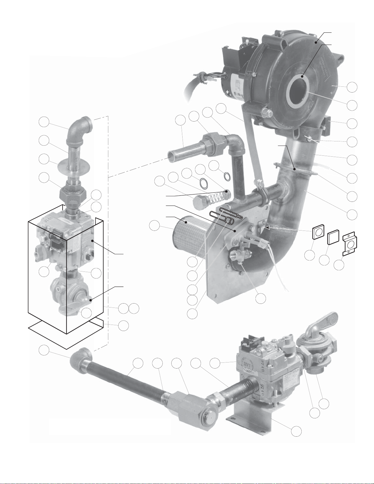
GAS CONTROL ASSEMBLY
1
16
37
17
18
19
20
21
3931 32 33 34
22
23
24
8
9
10
2
3
30
35
29
4
5
6
4
7
11
13
14
12
15
38
25
25
26
27
22
28
29
28
30
Stationary Models
Tilting
Models
34
Air Blower
Primary
Air Orifice
Secondary
Air
Orifice
Gas Orifice
Ignitor
Burner
Gas Valve
Shut-Off Valve
40 41
42
(for units built prior to March 2005)
Page 18

GAS CONTROL ASSEMBLY
ITEM ON. PART NO. DESCRIPTION QTY.
1. KE53441 BLOWER, 115V, 60 HZ . . . . . . . . . . . . . . . . . . . . . . . . . . . . . . . . . . . . . . . . . . . . . . . . . . . . . . . . . . . . . . . . . . . .1
KE53441-1 BLOWER, 220V, 50 HZ . . . . . . . . . . . . . . . . . . . . . . . . . . . . . . . . . . . . . . . . . . . . . . . . . . . . . . . . . . . . . . . . . . . .1
2. KE54420 AIR INTAKE WASHER (NATURAL GAS) . . . . . . . . . . . . . . . . . . . . . . . . . . . . . . . . . . . . . . . . . . . . . . . . . . . . . . .1
KE54420-1 AIR INTAKE WASHER (PROPANE) . . . . . . . . . . . . . . . . . . . . . . . . . . . . . . . . . . . . . . . . . . . . . . . . . . . . . . . . . . .1
3. KE54239 CAPACITOR . . . . . . . . . . . . . . . . . . . . . . . . . . . . . . . . . . . . . . . . . . . . . . . . . . . . . . . . . . . . . . . . . . . . . . . . . . . . .1
4. KE01426-4 MIXING CHAMBER, 40 GALLON KETTLES . . . . . . . . . . . . . . . . . . . . . . . . . . . . . . . . . . . . . . . . . . . . . . . . . . . .1
KE01426-1 MIXING CHAMBER, 60 GALLON KETTLES . . . . . . . . . . . . . . . . . . . . . . . . . . . . . . . . . . . . . . . . . . . . . . . . . . . .1
KE01426-2 MIXING CHAMBER, 80 GALLON KETTLES . . . . . . . . . . . . . . . . . . . . . . . . . . . . . . . . . . . . . . . . . . . . . . . . . . . .1
KE01426-3 MIXING CHAMBER, 100 GALLON KETTLES . . . . . . . . . . . . . . . . . . . . . . . . . . . . . . . . . . . . . . . . . . . . . . . . . . .1
5. KE53582 TUBING 1/4 INCH SILICONE . . . . . . . . . . . . . . . . . . . . . . . . . . . . . . . . . . . . . . . . . . . . . . . . . . . . . . . . . . . . . . .1
FI05156 HOSE FITTING . . . . . . . . . . . . . . . . . . . . . . . . . . . . . . . . . . . . . . . . . . . . . . . . . . . . . . . . . . . . . . . . . . . . . . . . . . .1
6. KE53402 AIR ORIFICE, 40 GALLON KETTLES . . . . . . . . . . . . . . . . . . . . . . . . . . . . . . . . . . . . . . . . . . . . . . . . . . . . . . . . .1
KE53402-1 AIR ORIFICE, 60 - 100 GALLON KETTLES . . . . . . . . . . . . . . . . . . . . . . . . . . . . . . . . . . . . . . . . . . . . . . . . . . . . .1
KE53402-2 AIR ORIFICE, 40 GALLON KETTLES (50 HZ BLOWER) . . . . . . . . . . . . . . . . . . . . . . . . . . . . . . . . . . . . . . . . . . .1
KE53402-3 AIR ORIFICE, 60 - 100 GALLON KETTLES (50 HZ BLOWER ) . . . . . . . . . . . . . . . . . . . . . . . . . . . . . . . . . . . . . .1
7. KE01449 BLOWER MOUNTING PIPE ASSEMBLY . . . . . . . . . . . . . . . . . . . . . . . . . . . . . . . . . . . . . . . . . . . . . . . . . . . . . . .1
8. KE53618 SIGHT GLASS GASKET . . . . . . . . . . . . . . . . . . . . . . . . . . . . . . . . . . . . . . . . . . . . . . . . . . . . . . . . . . . . . . . . . . . .1
9. KE53617 SIGHT GLASS . . . . . . . . . . . . . . . . . . . . . . . . . . . . . . . . . . . . . . . . . . . . . . . . . . . . . . . . . . . . . . . . . . . . . . . . . . .1
10. KE53619 SIGHT GLASS RETAINER . . . . . . . . . . . . . . . . . . . . . . . . . . . . . . . . . . . . . . . . . . . . . . . . . . . . . . . . . . . . . . . . . .1
11. KE00515 THERMISTOR . . . . . . . . . . . . . . . . . . . . . . . . . . . . . . . . . . . . . . . . . . . . . . . . . . . . . . . . . . . . . . . . . . . . . . . . . . . .1
12. KE50556-2 WATER LEVEL PROBE . . . . . . . . . . . . . . . . . . . . . . . . . . . . . . . . . . . . . . . . . . . . . . . . . . . . . . . . . . . . . . . . . . . . .1
13. KE53437-3 IGNITOR . . . . . . . . . . . . . . . . . . . . . . . . . . . . . . . . . . . . . . . . . . . . . . . . . . . . . . . . . . . . . . . . . . . . . . . . . . . . . . . .1
14. KE53570 GASKET FOR IGNITOR . . . . . . . . . . . . . . . . . . . . . . . . . . . . . . . . . . . . . . . . . . . . . . . . . . . . . . . . . . . . . . . . . . . .1
15. FI05257 SHUT-OFF COCK . . . . . . . . . . . . . . . . . . . . . . . . . . . . . . . . . . . . . . . . . . . . . . . . . . . . . . . . . . . . . . . . . . . . . . . . .1
16. FI05213 PLUG . . . . . . . . . . . . . . . . . . . . . . . . . . . . . . . . . . . . . . . . . . . . . . . . . . . . . . . . . . . . . . . . . . . . . . . . . . . . . . . . . .1
17. KE53422 SPRING . . . . . . . . . . . . . . . . . . . . . . . . . . . . . . . . . . . . . . . . . . . . . . . . . . . . . . . . . . . . . . . . . . . . . . . . . . . . . . . .1
18. FA05002-4 “O” RING . . . . . . . . . . . . . . . . . . . . . . . . . . . . . . . . . . . . . . . . . . . . . . . . . . . . . . . . . . . . . . . . . . . . . . . . . . . . . . .1
19. GAS ORIFICES:
KE53403-8 NATURAL GAS - SEA LEVEL UP TO 2000', 40 GALLON KETTLES . . . . . . . . . . . . . . . . . . . . . . . . . . . . . . . . . .1
KE53403-5 PROPANE GAS - SEA LEVEL UP TO 2000', 40 GALLON KETTLES . . . . . . . . . . . . . . . . . . . . . . . . . . . . . . . . . .1
KE53403-6 NATURAL GAS - SEA LEVEL UP TO 2000', 60 - 100 GALLON KETTLES . . . . . . . . . . . . . . . . . . . . . . . . . . . . .1
KE53403-7 PROPANE GAS - SEA LEVEL UP TO 2000', 60 - 100 GALLON KETTLES . . . . . . . . . . . . . . . . . . . . . . . . . . . . .1
KE53403-8 NATURAL GAS - 2000' UP TO 4000', 40 GALLON KETTLES . . . . . . . . . . . . . . . . . . . . . . . . . . . . . . . . . . . . . . .1
KE53403-9 PROPANE GAS - 2000' UP TO 4000', 40 GALLON KETTLES . . . . . . . . . . . . . . . . . . . . . . . . . . . . . . . . . . . . . .1
KE53403-10 NATURAL GAS - 2000' UP TO 4000', 60 - 100 GALLON KETTLES . . . . . . . . . . . . . . . . . . . . . . . . . . . . . . . . . .1
KE53403-11 PROPANE GAS - 2000' TO 4000', 60 - 100 GALLON KETTLES . . . . . . . . . . . . . . . . . . . . . . . . . . . . . . . . . . . . .1
KE53403-12 NATURAL GAS - 4000' UP TO 6000', 40 GALLON KETTLES . . . . . . . . . . . . . . . . . . . . . . . . . . . . . . . . . . . . . . .1
KE53403-13 PROPANE GAS - 4000' UP TO 6000', 40 GALLON KETTLES . . . . . . . . . . . . . . . . . . . . . . . . . . . . . . . . . . . . . .1
KE53403-10 NATURAL GAS - 4000' UP TO 6000', 60 - 100 GALLON KETTLES . . . . . . . . . . . . . . . . . . . . . . . . . . . . . . . . . .1
KE53403-14 PROPANE GAS - 4000' UP TO 6000', 60 - 100 GALLON KETTLES . . . . . . . . . . . . . . . . . . . . . . . . . . . . . . . . . .1
20. FA05002-29 “O” RING . . . . . . . . . . . . . . . . . . . . . . . . . . . . . . . . . . . . . . . . . . . . . . . . . . . . . . . . . . . . . . . . . . . . . . . . . . . . . . .1
21. FI05226-4 NIPPLE, 1/2" NPT, 5 5/16" LONG . . . . . . . . . . . . . . . . . . . . . . . . . . . . . . . . . . . . . . . . . . . . . . . . . . . . . . . . . . . . .1
22. FI00073 UNION, 1/2" . . . . . . . . . . . . . . . . . . . . . . . . . . . . . . . . . . . . . . . . . . . . . . . . . . . . . . . . . . . . . . . . . . . . . . . . . . . . .1
23. FI00133 ELBOW, 1/2", STREET . . . . . . . . . . . . . . . . . . . . . . . . . . . . . . . . . . . . . . . . . . . . . . . . . . . . . . . . . . . . . . . . . . . . .1
24. KE93909 STRIP, TO HOLD BLOWER DOWN . . . . . . . . . . . . . . . . . . . . . . . . . . . . . . . . . . . . . . . . . . . . . . . . . . . . . . . . . . .1
25. FI00040-1 ELBOW, 1/2" . . . . . . . . . . . . . . . . . . . . . . . . . . . . . . . . . . . . . . . . . . . . . . . . . . . . . . . . . . . . . . . . . . . . . . . . . . . . .1
26. FI00579 NIPPLE, 1/2" NPT, 4" LONG, KGL-60-T . . . . . . . . . . . . . . . . . . . . . . . . . . . . . . . . . . . . . . . . . . . . . . . . . . . . . . . .1
FI05226-2 NIPPLE, 1/2" NPT, 4" LONG, KGL-80-T . . . . . . . . . . . . . . . . . . . . . . . . . . . . . . . . . . . . . . . . . . . . . . . . . . . . . . . .1
27. KE55004-3 RETAINING PLATE . . . . . . . . . . . . . . . . . . . . . . . . . . . . . . . . . . . . . . . . . . . . . . . . . . . . . . . . . . . . . . . . . . . . . . . .1
28. FI00573 NIPPLE, 1/2" NPT, 1 1/8" LONG . . . . . . . . . . . . . . . . . . . . . . . . . . . . . . . . . . . . . . . . . . . . . . . . . . . . . . . . . . . . . .1
29. FI05231 BUSHING, 3/4 - 1/2" NPT FLUSH, BLACK IRON . . . . . . . . . . . . . . . . . . . . . . . . . . . . . . . . . . . . . . . . . . . . . . . .1
30.
F01518-1 GAS SHUT-OFF VALVE, 3/4" (NOT FOR FRENCH CE KETTLES) . . . . . . . . . . . . . . . . . . . . . . . . . . . . . . . . . . . .1
31. FI05226 NIPPLE, 1/2" NPT, 8" LONG . . . . . . . . . . . . . . . . . . . . . . . . . . . . . . . . . . . . . . . . . . . . . . . . . . . . . . . . . . . . . . . . .1
32. FI05222 SWIVEL ELBOW . . . . . . . . . . . . . . . . . . . . . . . . . . . . . . . . . . . . . . . . . . . . . . . . . . . . . . . . . . . . . . . . . . . . . . . . . .1
33. FI05223 SPECIAL NIPPLE . . . . . . . . . . . . . . . . . . . . . . . . . . . . . . . . . . . . . . . . . . . . . . . . . . . . . . . . . . . . . . . . . . . . . . . . .1
34. KE02053 GAS VALVE ASSEMBLY . . . . . . . . . . . . . . . . . . . . . . . . . . . . . . . . . . . . . . . . . . . . . . . . . . . . . . . . . . . . . . . . . . . .1
35. KE53390 BRACKET FOR GAS VALVE . . . . . . . . . . . . . . . . . . . . . . . . . . . . . . . . . . . . . . . . . . . . . . . . . . . . . . . . . . . . . . . . .1
36. FI00607 NIPPLE, 3/4" NPT, 1 1/2" LONG . . . . . . . . . . . . . . . . . . . . . . . . . . . . . . . . . . . . . . . . . . . . . . . . . . . . . . . . . . . . . .1
37. KE01500-5 BURNER, 40 GALLON KETTLES, 140,000 BTU . . . . . . . . . . . . . . . . . . . . . . . . . . . . . . . . . . . . . . . . . . . . . . . . .1
KE01500-1 BURNER, 60-100 GALLON KETTLES, 190,000 BTU . . . . . . . . . . . . . . . . . . . . . . . . . . . . . . . . . . . . . . . . . . . . .1
38. KE53397 GASKET, BURNER . . . . . . . . . . . . . . . . . . . . . . . . . . . . . . . . . . . . . . . . . . . . . . . . . . . . . . . . . . . . . . . . . . . . . . . .1
39. FI05231 ADAPTOR . . . . . . . . . . . . . . . . . . . . . . . . . . . . . . . . . . . . . . . . . . . . . . . . . . . . . . . . . . . . . . . . . . . . . . . . . . . . . .1
40. KE601085 COVER FOR GAS VALVE . . . . . . . . . . . . . . . . . . . . . . . . . . . . . . . . . . . . . . . . . . . . . . . . . . . . . . . . . . . . . . . . . . .1
41. RB018151 GASKET FOR COVER . . . . . . . . . . . . . . . . . . . . . . . . . . . . . . . . . . . . . . . . . . . . . . . . . . . . . . . . . . . . . . . . . . . . .1
42. KE601081 BRACKET . . . . . . . . . . . . . . . . . . . . . . . . . . . . . . . . . . . . . . . . . . . . . . . . . . . . . . . . . . . . . . . . . . . . . . . . . . . . . . .1
Page 19

GAS CONTROL ASSEMBLY
(for units built after February 2005)
1. FI00040-1 ELBOW, 1/2" . . . . . . . . . . . . . . . . . . . . . . . . . . . . . . . . . . . . . . . . . . . . . . . . . . . . . . . . . . . . . . . . .1
2. FI05226 NIPPLE, 1/2" NPT, 8" LONG . . . . . . . . . . . . . . . . . . . . . . . . . . . . . . . . . . . . . . . . . . . . . . . . . . . . .1
3. FI05231 ADAPTOR . . . . . . . . . . . . . . . . . . . . . . . . . . . . . . . . . . . . . . . . . . . . . . . . . . . . . . . . . . . . . . . . . . .1
4. FI05222 SWIVEL ELBOW . . . . . . . . . . . . . . . . . . . . . . . . . . . . . . . . . . . . . . . . . . . . . . . . . . . . . . . . . . . . . .1
5. FI05223 SPECIAL NIPPLE . . . . . . . . . . . . . . . . . . . . . . . . . . . . . . . . . . . . . . . . . . . . . . . . . . . . . . . . . . . . .1
6. KE55240R GAS VALVE . . . . . . . . . . . . . . . . . . . . . . . . . . . . . . . . . . . . . . . . . . . . . . . . . . . . . . . . . . . . . . . . . .1
7. F015 GAS SHUT-OFF VALVE, 3/4" . . . . . . . . . . . . . . . . . . . . . . . . . . . . . . . . . . . . . . . . . . . . . . . . . . . . .1
8. KE000960 NIPPLE PLATE WELDMENT . . . . . . . . . . . . . . . . . . . . . . . . . . . . . . . . . . . . . . . . . . . . . . . . . . . . .1
9. FA30505-1 WASHER, 1/4” . . . . . . . . . . . . . . . . . . . . . . . . . . . . . . . . . . . . . . . . . . . . . . . . . . . . . . . . . . . . . . .4
10. FA11256 HEX BOLT, 1/4-20 X 1/2, 18-8 SS . . . . . . . . . . . . . . . . . . . . . . . . . . . . . . . . . . . . . . . . . . . . . . . . .4
1
2
3
4
10
9
6
5
7
Tilting
8
Models
Page 20

GEARBOX ASSEMBLY
40
41
42
26 27 28
39
4
5
6
5
7
5
6
5
4
8
25
15
14
1
10
2
3
9
11
12
13
16 19 20
21
22
32
30
32
31
242324
23
36
34
33
35
37
38
Page 21

GEARBOX ASSEMBLY
ITEM NO. PART NO. DESCRIPTION QTY.
1. KE54644 TILT SHAFT, MANUAL TILT . . . . . . . . . . . . . . . . . . . . . . . . . . . . . . . . . . . . .1
KE52836-2 TILT SHAFT, POWER TILT . . . . . . . . . . . . . . . . . . . . . . . . . . . . . . . . . . . . . . .1
2. KE50315 WORM . . . . . . . . . . . . . . . . . . . . . . . . . . . . . . . . . . . . . . . . . . . . . . . . . . . . .1
3. FA95005 TENSION PIN . . . . . . . . . . . . . . . . . . . . . . . . . . . . . . . . . . . . . . . . . . . . . . . .1
4. KE52193-1 THRUST BEARING SPACER . . . . . . . . . . . . . . . . . . . . . . . . . . . . . . . . . . . .2
5. KE52192 THRUST WASHER . . . . . . . . . . . . . . . . . . . . . . . . . . . . . . . . . . . . . . . . . . . .4
6. KE52191 ROLLER BEARING . . . . . . . . . . . . . . . . . . . . . . . . . . . . . . . . . . . . . . . . . . . .2
7. FA30088 WASHER . . . . . . . . . . . . . . . . . . . . . . . . . . . . . . . . . . . . . . . . . . . . . . . . . . . .2
8. FA95008 JAM NUTS . . . . . . . . . . . . . . . . . . . . . . . . . . . . . . . . . . . . . . . . . . . . . . . . . .2
9. KE55057-4 LID FOR GEARBOX . . . . . . . . . . . . . . . . . . . . . . . . . . . . . . . . . . . . . . . . . . .1
10. FA95062 PAN HD. PHILLIPS SCREW . . . . . . . . . . . . . . . . . . . . . . . . . . . . . . . . . . . . .2
11. KE00508 HANDWHEEL ASSEMBLY . . . . . . . . . . . . . . . . . . . . . . . . . . . . . . . . . . . . . .1
12. FA19505 HANDWHEEL ALLEN SCREW, HEX SOCKET . . . . . . . . . . . . . . . . . . . . . . .1
13. KE51730 TILT SHAFT BEARING . . . . . . . . . . . . . . . . . . . . . . . . . . . . . . . . . . . . . . . . .1
14. FA19177 HEX SOCKET SET SCREW 5/16-24 X 1" . . . . . . . . . . . . . . . . . . . . . . . . . . .1
15. FA20047 JAM NUT 5/16-24 . . . . . . . . . . . . . . . . . . . . . . . . . . . . . . . . . . . . . . . . . .1
16. KE003209-11 Complete Switch . . . . . . . . . . . . . . . . . . . . . . . . . . . . . . . . . . . . . . . . . .1
KE603208-4 Momentary Switch Activator*** . . . . . . . . . . . . . . . . . . . . . . . . . . . . . . .1
KE603208-7 Contact Section Holder, Latch*** . . . . . . . . . . . . . . . . . . . . . . . . . . . . . .1
KE603208-9 Contact Block*** . . . . . . . . . . . . . . . . . . . . . . . . . . . . . . . . . . . . . . . . . . 4
***NOTE: for units built prior to Dec. 2006 order Complete Switch KE003209-11
19. KE50580 WATER RESISTANT BOOT . . . . . . . . . . . . . . . . . . . . . . . . . . . . . . . . . . .1
20. FA05002-34 "O" RING, CIRCUIT BREAKER . . . . . . . . . . . . . . . . . . . . . . . . . . . . . . . . . . .1
21. KE50579-1 CIRCUIT BREAKER . . . . . . . . . . . . . . . . . . . . . . . . . . . . . . . . . . . . . . . . . . .1
22. KE51007 MICRO SWITCH . . . . . . . . . . . . . . . . . . . . . . . . . . . . . . . . . . . . . . . . . . . . . .2
FA10139 MACHINE SCREW #6-32 X 1" LG . . . . . . . . . . . . . . . . . . . . . . . . . . . . . . . .4
KE50498 MICRO SWITCH INSULATION . . . . . . . . . . . . . . . . . . . . . . . . . . . . . . . . . . .2
FA32004 TOOTH LOCK WASHER #6 . . . . . . . . . . . . . . . . . . . . . . . . . . . . . . . . . . . . .4
23. KE50582 CPLG. ONTARIO BELTING #G-100 5/8 BORE . . . . . . . . . . . . . . . . . . . . . . .2
24. FA95055-6 SQUARE KEY 3/16 X 3/16 X 1" LG . . . . . . . . . . . . . . . . . . . . . . . . . . . . . . .1
25. KE50583 RUBBER INSERT, ONTARIO BELTING "BUNA N" . . . . . . . . . . . . . . . . . . . .1
26. KE52832-1 MOTOR . . . . . . . . . . . . . . . . . . . . . . . . . . . . . . . . . . . . . . . . . . . . . . . . . . . . .1
27. FA10487 HEX HD SCREW 1/4-20 X 1" LG . . . . . . . . . . . . . . . . . . . . . . . . . . . . . . . . .4
28. FA31008 SPLIT LOCKWASHER 1/4" DIA . . . . . . . . . . . . . . . . . . . . . . . . . . . . . . . . . .4
29. FA20026 HEX NUT 1/4 - 20 . . . . . . . . . . . . . . . . . . . . . . . . . . . . . . . . . . . . . . . . . . . . .4
30. KE517112 LEFT HAND BEARING . . . . . . . . . . . . . . . . . . . . . . . . . . . . . . . . . . . . . . . . .1
31. KE517111 RIGHT HAND BEARING . . . . . . . . . . . . . . . . . . . . . . . . . . . . . . . . . . . . . . . .1
32. KE51712 GREASE NIPPLE . . . . . . . . . . . . . . . . . . . . . . . . . . . . . . . . . . . . . . . . . . . . .2
33. KE01889 MICRO SWITCH TRIGGER/SEGMENT GEAR WELDMENT . . . . . . . . . . . . .1
34. FA10772 SOCKET HD. CAP SCREW . . . . . . . . . . . . . . . . . . . . . . . . . . . . . . . . . . . . .2
35. FA20048 JAM NUT . . . . . . . . . . . . . . . . . . . . . . . . . . . . . . . . . . . . . . . . . . . . . . . . . . .2
36. FA95007-4 RETAINING RING . . . . . . . . . . . . . . . . . . . . . . . . . . . . . . . . . . . . . . . . . . . . .1
37. FA95055-1 SQUARE KEY . . . . . . . . . . . . . . . . . . . . . . . . . . . . . . . . . . . . . . . . . . . . . . . .1
38. FA19201 HEX SOCKET SET SCREW 3/8-24 . . . . . . . . . . . . . . . . . . . . . . . . . . . . . . . .1
39. KE50581 BRIDGE RECTIFIER . . . . . . . . . . . . . . . . . . . . . . . . . . . . . . . . . . . . . . . . . . .1
40. KE54535 EDGE CONNECTOR (11 PIN) . . . . . . . . . . . . . . . . . . . . . . . . . . . . . . . . . . .2
41. KE50753-10 RELAY . . . . . . . . . . . . . . . . . . . . . . . . . . . . . . . . . . . . . . . . . . . . . . . . . . . . . .2
42. KE50473 GROUND LUG . . . . . . . . . . . . . . . . . . . . . . . . . . . . . . . . . . . . . . . . . . . . . . .1
Page 22

BUTTERFLY VALVE
ITEM NO. PART NO. DESCRIPTION QTY.
1. - 7. KE51603 Butterfly Valve, 2" (includes housing) . . . . . . . . . . . . . . . . . . . . . . . . . . .1
KE52286 Butterfly Valve, 3" (includes housing) . . . . . . . . . . . . . . . . . . . . . . . . . . .1
1. FA11224 Bolt, 5/16-18 x1" S.S. . . . . . . . . . . . . . . . . . . . . . . . . . . . . . . . . . . . . . . . .4
2. FA21024 Nut, 5/16-18 . . . . . . . . . . . . . . . . . . . . . . . . . . . . . . . . . . . . . . . . . . . . . .4
3. SE50433 Seat, 2" . . . . . . . . . . . . . . . . . . . . . . . . . . . . . . . . . . . . . . . . . . . . . . . . . .1
SE50433-1 Seat, 3" . . . . . . . . . . . . . . . . . . . . . . . . . . . . . . . . . . . . . . . . . . . . . . . . . .1
4. SE50434 Stem, 2" . . . . . . . . . . . . . . . . . . . . . . . . . . . . . . . . . . . . . . . . . . . . . . . . .1
SE50434-1 Stem, 3" . . . . . . . . . . . . . . . . . . . . . . . . . . . . . . . . . . . . . . . . . . . . . . . . .1
5. SE50435 Locking Spider, 2" . . . . . . . . . . . . . . . . . . . . . . . . . . . . . . . . . . . . . . . . .1
SE50435-1 Locking Spider, 3" . . . . . . . . . . . . . . . . . . . . . . . . . . . . . . . . . . . . . . . . .1
6. SE50436 Handle Assembly . . . . . . . . . . . . . . . . . . . . . . . . . . . . . . . . . . . . . . . . . .1
7. SE50437 Allen Bolt . . . . . . . . . . . . . . . . . . . . . . . . . . . . . . . . . . . . . . . . . . . . . . . .1
Rev 1
3
4
5
6
7
1
2
Page 23

FLUSH PISTON VALVE
(USED PRIOR TO 2003)
ITEM NO. PART NO. DESCRIPTION QTY.
T40430 Valve Assembly (includes parts 1 - 16) . . . . . . . . . . . . . . . . . . . . . . . . .1
1. FA05000 "O" Ring, Cylinder Head . . . . . . . . . . . . . . . . . . . . . . . . . . . . . . . . . . . . .1
2. KE52345 Piston Shaft . . . . . . . . . . . . . . . . . . . . . . . . . . . . . . . . . . . . . . . . . . . . . . .1
3. KE52346 Air seal . . . . . . . . . . . . . . . . . . . . . . . . . . . . . . . . . . . . . . . . . . . . . . . . . .1
4. KE52347 Sani-Clamp Seal, 4” . . . . . . . . . . . . . . . . . . . . . . . . . . . . . . . . . . . . . . .1
5. KE52344 Sani-Clamp, 4” . . . . . . . . . . . . . . . . . . . . . . . . . . . . . . . . . . . . . . . . . . . .1
6. FA05002-22 "O" Ring, Cylinder Body . . . . . . . . . . . . . . . . . . . . . . . . . . . . . . . . . . . . .2
7. FA05002-21 "O" Ring, Piston . . . . . . . . . . . . . . . . . . . . . . . . . . . . . . . . . . . . . . . . . . . .2
8. KE52315 Piston . . . . . . . . . . . . . . . . . . . . . . . . . . . . . . . . . . . . . . . . . . . . . . . . . . .1
9. KE52335 Compression Spring . . . . . . . . . . . . . . . . . . . . . . . . . . . . . . . . . . . . . . . .1
10.-13. SE00040 Supply Hose Assembly, Piston . . . . . . . . . . . . . . . . . . . . . . . . . . . . . . . .1
10. KE52341 Hose Barb, 1/8” x 1/4” . . . . . . . . . . . . . . . . . . . . . . . . . . . . . . . . . . . . . .3
11. KE52340 Supply Hose, 8” . . . . . . . . . . . . . . . . . . . . . . . . . . . . . . . . . . . . . . . . . . .1
12. KE52342 Hose Barb, 1/4” x 1/4” . . . . . . . . . . . . . . . . . . . . . . . . . . . . . . . . . . . . . .1
13. KE52338 Quick Connect Male End . . . . . . . . . . . . . . . . . . . . . . . . . . . . . . . . . . . .1
14. KE52327 Piston Top . . . . . . . . . . . . . . . . . . . . . . . . . . . . . . . . . . . . . . . . . . . . . . . .1
15. KE52328 Piston Cylinder . . . . . . . . . . . . . . . . . . . . . . . . . . . . . . . . . . . . . . . . . . . .1
16. KE52314 Bottom Nut . . . . . . . . . . . . . . . . . . . . . . . . . . . . . . . . . . . . . . . . . . . . . . .1
Page 24

FLUSH PISTON AIR SYSTEM, 10" CONSOLE
(USED PRIOR TO 2003)
ITEM NO. PART NO. DESCRIPTION QTY.
1. FA30512 Spacer . . . . . . . . . . . . . . . . . . . . . . . . . . . . . . . . . . . . . . . . . . . . . . . . . . . . . . . . .1
2. FA32500 Tooth lockwasher . . . . . . . . . . . . . . . . . . . . . . . . . . . . . . . . . . . . . . . . . . . . . . . . .1
3. KE52697 Locking nut . . . . . . . . . . . . . . . . . . . . . . . . . . . . . . . . . . . . . . . . . . . . . . . . . . . . .1
4. KE52931 Adapter . . . . . . . . . . . . . . . . . . . . . . . . . . . . . . . . . . . . . . . . . . . . . . . . . . . . . . . .1
5. FI00266 Coupling . . . . . . . . . . . . . . . . . . . . . . . . . . . . . . . . . . . . . . . . . . . . . . . . . . . . . . .1
6. FI00595-17 Nipple 1/2" NPT . . . . . . . . . . . . . . . . . . . . . . . . . . . . . . . . . . . . . . . . . . . . . . . . . .2
7. FI00178 Tee 1/2" NPT . . . . . . . . . . . . . . . . . . . . . . . . . . . . . . . . . . . . . . . . . . . . . . . . . . . .2
8. FI00595-12 Nipple 1/2" NPT . . . . . . . . . . . . . . . . . . . . . . . . . . . . . . . . . . . . . . . . . . . . . . . . . .1
9. FI05047 Bushing . . . . . . . . . . . . . . . . . . . . . . . . . . . . . . . . . . . . . . . . . . . . . . . . . . . . . . . .1
10. KE52342 Hose Barb . . . . . . . . . . . . . . . . . . . . . . . . . . . . . . . . . . . . . . . . . . . . . . . . . . . . . .3
11. FI05167 Hose Barb 90 Degree Elbow . . . . . . . . . . . . . . . . . . . . . . . . . . . . . . . . . . . . . . .6
12. KE52815 Airline Lubricator . . . . . . . . . . . . . . . . . . . . . . . . . . . . . . . . . . . . . . . . . . . . . . . . .1
13. KE52895 Air Regulator . . . . . . . . . . . . . . . . . . . . . . . . . . . . . . . . . . . . . . . . . . . . . . . . . . . .1
14. KE52339 Female End Quick Connect . . . . . . . . . . . . . . . . . . . . . . . . . . . . . . . . . . . . . . . .1
15. KE52932 Bracket For Lubricator . . . . . . . . . . . . . . . . . . . . . . . . . . . . . . . . . . . . . . . . . . . .1
16. FA32006 Toothlock Washer . . . . . . . . . . . . . . . . . . . . . . . . . . . . . . . . . . . . . . . . . . . . . . . .4
17. FA21006 Nut . . . . . . . . . . . . . . . . . . . . . . . . . . . . . . . . . . . . . . . . . . . . . . . . . . . . . . . . . . . .4
18. FA11091 Machine Screw . . . . . . . . . . . . . . . . . . . . . . . . . . . . . . . . . . . . . . . . . . . . . . . . . .2
19. KE53209 Quick Exhaust Valve . . . . . . . . . . . . . . . . . . . . . . . . . . . . . . . . . . . . . . . . . . . . . .1
20. KE53210 Muffler . . . . . . . . . . . . . . . . . . . . . . . . . . . . . . . . . . . . . . . . . . . . . . . . . . . . . . . . .1
21. KE52031 Air Line Filter c/w Bracket . . . . . . . . . . . . . . . . . . . . . . . . . . . . . . . . . . . . . . . . . .1
22. KE53251 Air Line Filter Bracket . . . . . . . . . . . . . . . . . . . . . . . . . . . . . . . . . . . . . . . . . . . . .1
23. FA11144 Bindinghead Screw . . . . . . . . . . . . . . . . . . . . . . . . . . . . . . . . . . . . . . . . . . . . . . .4
24. FI05166 Quick connect . . . . . . . . . . . . . . . . . . . . . . . . . . . . . . . . . . . . . . . . . . . . . . . . . . .1
25. KE54280 Slide valve . . . . . . . . . . . . . . . . . . . . . . . . . . . . . . . . . . . . . . . . . . . . . . . . . . . . . .1
26. KE53215 1/4" Air Hose, 65" Long . . . . . . . . . . . . . . . . . . . . . . . . . . . . . . . . . . . . . . . . . . . .1
Page 25

FLUSH PISTON LUBRICATOR
(USED PRIOR TO 2003)
ITEM NO. PART NO. DESCRIPTION QTY.
1. FA30512 Spacer . . . . . . . . . . . . . . . . . . . . . . . . . . . . . . . . . . . . . . . . . . . . . . . . . . . . . . . . .1
1.-5 KE52815 Lubricator c/w Bracket . . . . . . . . . . . . . . . . . . . . . . . . . . . . . . . . . . . . . .1
1. SE50418 Sight Dome Assembly . . . . . . . . . . . . . . . . . . . . . . . . . . . . . . . . . . . . . .1
2. SE50419 Filler Cap Assembly . . . . . . . . . . . . . . . . . . . . . . . . . . . . . . . . . . . . . . . .1
3. SE50420 Needle Valve Assembly . . . . . . . . . . . . . . . . . . . . . . . . . . . . . . . . . . . . .1
4. SE50422 "O" Ring . . . . . . . . . . . . . . . . . . . . . . . . . . . . . . . . . . . . . . . . . . . . . . . . .1
5. SE50423 Bowl/Guard Assembly . . . . . . . . . . . . . . . . . . . . . . . . . . . . . . . . . . . . . .1
FLUSH PISTON FILTER
(USED PRIOR TO 2003)
ITEM NO. PART NO. DESCRIPTION QTY.
1.-5 KE52031 Filter c/w Bracket . . . . . . . . . . . . . . . . . . . . . . . . . . . . . . . . . . . . . . . . . . . . . . . .1
1. SE50425 Deflector . . . . . . . . . . . . . . . . . . . . . . . . . . . . . . . . . . . . . . . . . . . . . . . . . . . . . . .1
2. SE50426 Filter Element . . . . . . . . . . . . . . . . . . . . . . . . . . . . . . . . . . . . . . . . . . . . . . . . . . . .1
3. SE50427 Baffle . . . . . . . . . . . . . . . . . . . . . . . . . . . . . . . . . . . . . . . . . . . . . . . . . . . . . . . . . .1
4. SE50428 "O" Ring . . . . . . . . . . . . . . . . . . . . . . . . . . . . . . . . . . . . . . . . . . . . . . . . . . . . . . . .1
5. SE50429 Bowl/Guard Assembly . . . . . . . . . . . . . . . . . . . . . . . . . . . . . . . . . . . . . . . . . . . . .1
Page 26

ITEM ON. PART NO. DESCRIPTION QTY.
1. KE55210 WELD RING, KETTLE BOTTOM OUTLET . . . . . . . . . . . . . . . . . . . . . . . . . . . . . 1
2. FI05144-3 SANI CLAMP, 3” . . . . . . . . . . . . . . . . . . . . . . . . . . . . . . . . . . . . . . . . . . . . . . . . . 2
3. KE52154-4 GASKET, SANI CLAMP, 3” . . . . . . . . . . . . . . . . . . . . . . . . . . . . . . . . . . . . . . . . . 2
4. KE02291 COMPLETE ACTUATOR AND DISCHARGE VALVE ASSEMBLY . . . . . . . . . . . . 1
INCLUDES PARTS 5. - 13.
5. KE55248 BUNA-N O-RING . . . . . . . . . . . . . . . . . . . . . . . . . . . . . . . . . . . . . . . . . . . . . . . . .1
6. KE55249 REPLACEABLE S.S. PLUNGER HEAD . . . . . . . . . . . . . . . . . . . . . . . . . . . . . . . .1
7. KE55250 BUNA-N O-RING . . . . . . . . . . . . . . . . . . . . . . . . . . . . . . . . . . . . . . . . . . . . . . . . .1
8. KE55251 1/8 NPT S.S. HYDRAULIC CLOSE NIPPLE . . . . . . . . . . . . . . . . . . . . . . . . . . . .2
9. KE55252 MALE S.S. QUICK DISCONNECT . . . . . . . . . . . . . . . . . . . . . . . . . . . . . . . . . . . .1
10. KE55253 AIR OPERATED CYLINDER . . . . . . . . . . . . . . . . . . . . . . . . . . . . . . . . . . . . . . . .1
11. KE55254 FEMALE S.S. QUICK DISCONNECT . . . . . . . . . . . . . . . . . . . . . . . . . . . . . . . . .1
12. KE55255 BUNA-N O-RING . . . . . . . . . . . . . . . . . . . . . . . . . . . . . . . . . . . . . . . . . . . . . . . . .2
13. KE55256 BODY, DISCHARGE VALVE . . . . . . . . . . . . . . . . . . . . . . . . . . . . . . . . . . . . . . . .1
1
3
2
12
13
12
5
6
7
8
10
9
8
11
4
AIR VALVE
ASSEMBLY
FPVA-3
FLUSH PISTON VALVE
(USED AFTER TO 2003)
Page 27

ITEM NO. PART NO. DESCRIPTION QTY.
I KE601603 QUICK CONNECT . . . . . . . . . . . . . . . . . . . . . . . . . . . . . . . . . . . . . . . . . . . . . . . .I
2 KE601601 SLIDE VALVE . . . . . . . . . . . . . . . . . . . . . . . . . . . . . . . . . . . . . . . . . . . . . . . . . . . .1
3 FA30512 SPACER WASHER . . . . . . . . . . . . . . . . . . . . . . . . . . . . . . . . . . . . . . . . . . . . . . . .i
4 FA32500 TOOTH LOCK WASHER 7/8 DIA, . . . . . . . . . . . . . . . . . . . . . . . . . . . . . . . . . . . .1
5 KE52697 NUT 1/2 NIPS BRASS . . . . . . . . . . . . . . . . . . . . . . . . . . . . . . . . . . . . . . . . . . . .~~
6 KE601602 AIR FITTING . . . . . . . . . . . . . . . . . . . . . . . . . . . . . . . . . . . . . . . . . . . . . . . . . . . . .I
7 KE600814-1 TEE 1/2 NPT (FIP x FIP x FIP) . . . . . . . . . . . . . . . . . . . . . . . . . . . . . . . . . . . . . . .I
8 FI00351 BUSHING 1/2 MIP x 1/4 FIP . . . . . . . . . . . . . . . . . . . . . . . . . . . . . . . . . . . . . . . .1
9 FI05318 HOSE BARB 90' ELBOW . . . . . . . . . . . . . . . . . . . . . . . . . . . . . . . . . . . . . . . . . .3
11 FA30090 WASHER 15/16 IDxl 3/4 ODxl/8 THK . . . . . . . . . . . . . . . . . . . . . . . . . . . . . . . . .1
13 KE02369 FILTER-REGULATOR ASSEMBLY . . . . . . . . . . . . . . . . . . . . . . . . . . . . . . . . . . . .1
14 FI05220-1 GEAR CLAMP . . . . . . . . . . . . . . . . . . . . . . . . . . . . . . . . . . . . . . . . . . . . . . . . . . .4
15 FA21002 #6-32 HEX NUT SS . . . . . . . . . . . . . . . . . . . . . . . . . . . . . . . . . . . . . . . . . . . . . . .4
16 KE532176 PNEUMATIC HOSE (1/4 I.D.xl2 1/2 LG.) . . . . . . . . . . . . . . . . . . . . . . . . . . . . . .1
FLUSH PISTON AIR SYSTEM, 10" CONSOLE
(USED AFTER TO 2003)
N1
N2
Page 28

FLUSH PISTON AIR SYSTEM, 10" CONSOLE
(USED AFTER TO 2003)
17 KE532177 PNEUMATIC HOSE, (1/4 I.D.x 31 LG.) . . . . . . . . . . . . . . . . . . . . . . . . . . . . . . . .1
18 FA32004 TOOTH LOCK WASHER, #6 ZINC PLATED . . . . . . . . . . . . . . . . . . . . . . . . . . . .4
19 SEE FOLLOWING PAGE: FLUSH PISTON - AIR SOLENOID VALVE (Used after to 2003)
20 KE50555-3 GROMMET . . . . . . . . . . . . . . . . . . . . . . . . . . . . . . . . . . . . . . . . . . . . . . . . . . . . .2
21 KE01812-1 SWITCH ON/OFF/ON (MAINT/MAINT/MOM) . . . . . . . . . . . . . . . . . . . . . . . . . . .1
24 KE95481-5 LABEL, PRODUCT DISCHARGE VALVE . . . . . . . . . . . . . . . . . . . . . . . . . . . . . . .1
25 KE55232 WIRING DIAGRAM FOR AIR VALVE (NOT SHOWN) . . . . . . . . . . . . . . . . . . . . .1
POWER TILT OPTION
30 KE02185 COMPONENT PLATE . . . . . . . . . . . . . . . . . . . . . . . . . . . . . . . . . . . . . . . . . . . . .1
32 FA21007 #10-32 HEX NUT SS . . . . . . . . . . . . . . . . . . . . . . . . . . . . . . . . . . . . . . . . . . . . . .2
33 FA40000-6 TOOTH LOCK WASHER, #10 ZINC PLATED . . . . . . . . . . . . . . . . . . . . . . . . . . .2
NIPPLES
for MKDL-40CC
N1 FI00595-17 NIPPLE, 1/2 NPT x 11 1/8 LG. BRASS . . . . . . . . . . . . . . . . . . . . . . . . . . . . . . . .1
N2 FI0059 5-12 NIPPLE, 1/2 NPT x 10 1/2LG. BRASS . . . . . . . . . . . . . . . . . . . . . . . . . . . . . . . . .1
for MKDL-60CC
N1 FI00595-17 NIPPLE, 1/2 NPT x 11 1/8 LG. BRASS . . . . . . . . . . . . . . . . . . . . . . . . . . . . . . . .1
N2 FI00595-13 NIPPLE, 1/2 NPT x B 7/8 LG. BRASS . . . . . . . . . . . . . . . . . . . . . . . . . . . . . . . . .1
for MKDL-80CC
N1 FI00595-17 NIPPLE, 1/2 NPT x 11 1/8 LG. BRASS . . . . . . . . . . . . . . . . . . . . . . . . . . . . . . . .1
N2 FI00595-14 NIPPLE, 1/2 NPT x 8 1/2 LG. BRASS . . . . . . . . . . . . . . . . . . . . . . . . . . . . . . . . .1
for MKDL-100CC
N1 FI00595-12 NIPPLE, 1/2 NPT x 10 1/2 LG. BRASS . . . . . . . . . . . . . . . . . . . . . . . . . . . . . . . .1
N2 FI00595-15 NIPPLE, 1/2 NPT x 6 7/8 LG. BRASS . . . . . . . . . . . . . . . . . . . . . . . . . . . . . . . . .1
for MKDL-125CC
N1 FI00595-19 NIPPLE, 1/2 NPT x 13 7/8 LG. BRASS . . . . . . . . . . . . . . . . . . . . . . . . . . . . . . .1
N2 FI00595-16 NIPPLE, 1/2 NPT x 7 5/8 LG. BRASS . . . . . . . . . . . . . . . . . . . . . . . . . . . . . . . . .1
for MKDL-150CC
N1 FI00595-12 NIPPLE, 1/2 NPT x 10 1/2 LG. BRASS . . . . . . . . . . . . . . . . . . . . . . . . . . . . . . . .1
N2 FI00595-7 NIPPLE, 1/2 NPT x 4 LG.BRASS . . . . . . . . . . . . . . . . . . . . . . . . . . . . . . . . . . . . .1
for MKDL-200CC
N1 FI00595-19 NIPPLE, 1/2 NPT x 13 7/8 LG. BRASS . . . . . . . . . . . . . . . . . . . . . . . . . . . . . . . .1
N2 FI00595-11 NIPPLE, 1/2 NPT x 6 LG. BRASS . . . . . . . . . . . . . . . . . . . . . . . . . . . . . . . . . . . .1
for MKDL-250CC
N1 FI00595-19 NIPPLE, 1/2 NPT x 13 7/8 LG. BRASS . . . . . . . . . . . . . . . . . . . . . . . . . . . . . . . .1
N2 FI00595-7 NIPPLE, 1/2 NPT x 4 LG. BRASS . . . . . . . . . . . . . . . . . . . . . . . . . . . . . . . . . . . .1
Page 29

ITEM ON. PART NO. DESCRIPTION QTY.
5. KE55257 MALE QUICK PLUG . . . . . . . . . . . . . . . . . . . . . . . . . . . . . . . . . . . . . . . . . . . . . .1
6. FI05317-1 HOSE BARB, 1/8' NPT MALE TO 1/4” HOSE . . . . . . . . . . . . . . . . . . . . . . . . . . .2
7. KE55259-1 1/4” ID X 6 FT LONG HOSE, 250 #W,P. . . . . . . . . . . . . . . . . . . . . . . . . . . . . . . .2
8. FI05317-2 HOSE BARB, 1/4” NPT MALE TO 1/4” HOSE . . . . . . . . . . . . . . . . . . . . . . . . . . .2
9. KE55261-1 EXHAUST MUFFLER, 1/8” . . . . . . . . . . . . . . . . . . . . . . . . . . . . . . . . . . . . . . . . .1
10 KE55262 FEMALE QUICK PLUG . . . . . . . . . . . . . . . . . . . . . . . . . . . . . . . . . . . . . . . . . . . .1
11. KE55263-1 5 WAY AIR SOLENOID VALVE . . . . . . . . . . . . . . . . . . . . . . . . . . . . . . . . . . . . . .1
12. KE55264-1 STANDARD 1/8” MUFFLER . . . . . . . . . . . . . . . . . . . . . . . . . . . . . . . . . . . . . . . . .1
13. FI05220-1 GEAR CLAMP FOR 1/4” I,D, HOSE (NOT SHOWN) . . . . . . . . . . . . . . . . . . . . . .5
14. FI05030-2 90° 1/4” ELBOW, MALE PIPE THREAD . . . . . . . . . . . . . . . . . . . . . . . . . . . . . . .1
15. KE55305 1/4” FLOW CONTROL . . . . . . . . . . . . . . . . . . . . . . . . . . . . . . . . . . . . . . . . . . . . .1
16. KE55259-2 /4” ID X 3 FT LONG HOSE, 250 #W,P. . . . . . . . . . . . . . . . . . . . . . . . . . . . . . . . .1
17. FI05318 90° ELBOW HOSE BARB/ 1/4” HOSE I,D./14” PIPE, BRASS . . . . . . . . . . . . . . .1
FLUSH PISTON AIR SOLENOID VALVE
(USED AFTER TO 2003)
Page 30

WATER METER ASSEMBLY 18" CONSOLE
Page 31

WATER METER ASSEMBLY 18" CONSOLE
ITEM NO. PART NO. DESCRIPTION QTY.
1. FI05058 3/4" Cross . . . . . . . . . . . . . . . . . . . . . . . . . . . . . . . . . . . . . . . . . . . . . . . . . . . . . .1
2. KE02055-2 Steam Valve Modification . . . . . . . . . . . . . . . . . . . . . . . . . . . . . . . . . . . . . . . . . .2
3. N0640B4.5 Nipple . . . . . . . . . . . . . . . . . . . . . . . . . . . . . . . . . . . . . . . . . . . . . . . . . . . . . . . . .2
4. FI00063 Elbow 90 degree . . . . . . . . . . . . . . . . . . . . . . . . . . . . . . . . . . . . . . . . . . . . . . . . .4
5. FI000356 Reducing Bushing . . . . . . . . . . . . . . . . . . . . . . . . . . . . . . . . . . . . . . . . . . . . . . . .1
6. KE600812-1 Street Elbow . . . . . . . . . . . . . . . . . . . . . . . . . . . . . . . . . . . . . . . . . . . . . . . . . . . .1
7. FI05029 Hose Barb . . . . . . . . . . . . . . . . . . . . . . . . . . . . . . . . . . . . . . . . . . . . . . . . . . . . . .2
8. KE54834-5 *
Solenoid Valve, 3/4"
. . . . . . . . . . . . . . . . . . . . . . . . . . . . . . . . . . . . . . . . . . . . .1
SE50407 Rebuild Kit
SE50401 Replacement Coil
9. N0640B3 Nipple, Gallon Meter . . . . . . . . . . . . . . . . . . . . . . . . . . . . . . . . . . . . . . . . . . . . . .1
N0640B3.5 Nipple, Litre Meter
10. FI00363-3 Reducing Elbow 90 Degree . . . . . . . . . . . . . . . . . . . . . . . . . . . . . . . . . . . . . . . .1
11. KE51861 Gallon Meter . . . . . . . . . . . . . . . . . . . . . . . . . . . . . . . . . . . . . . . . . . . . . . . . . . . .1
KE51860 Litre Meter
12. FI00062 Elbow 90 Degree . . . . . . . . . . . . . . . . . . . . . . . . . . . . . . . . . . . . . . . . . . . . . . . . .1
13. KE52173 1/2"1.D. Hot Water Wash-up Hose . . . . . . . . . . . . . . . . . . . . . . . . . . . . . . . . . . .1
14. FI05220-3 Hose Clamp . . . . . . . . . . . . . . . . . . . . . . . . . . . . . . . . . . . . . . . . . . . . . . . . . . . .2
15. FI00179 Tee . . . . . . . . . . . . . . . . . . . . . . . . . . . . . . . . . . . . . . . . . . . . . . . . . . . . . . . . . . . .1
16. FI05074 Adapter, Gallon Meter . . . . . . . . . . . . . . . . . . . . . . . . . . . . . . . . . . . . . . . . . . . . .2
KE600362 Adapter, Litre Meter
17. N0640B1.5 Nipple . . . . . . . . . . . . . . . . . . . . . . . . . . . . . . . . . . . . . . . . . . . . . . . . . . . . . . . . .1
18. FA11091 Machine Screw . . . . . . . . . . . . . . . . . . . . . . . . . . . . . . . . . . . . . . . . . . . . . . . . . .8
20. KE51369 Steam Valve Flange . . . . . . . . . . . . . . . . . . . . . . . . . . . . . . . . . . . . . . . . . . . . . .2
21. SE00028 Knob Assembly . . . . . . . . . . . . . . . . . . . . . . . . . . . . . . . . . . . . . . . . . . . . . . . . . .2
22. KE95321 Label "Hot" . . . . . . . . . . . . . . . . . . . . . . . . . . . . . . . . . . . . . . . . . . . . . . . . . . . . . .1
23. KE95322 Label "Cold" . . . . . . . . . . . . . . . . . . . . . . . . . . . . . . . . . . . . . . . . . . . . . . . . . . . . .1
24. SD50097 Flanged Nut . . . . . . . . . . . . . . . . . . . . . . . . . . . . . . . . . . . . . . . . . . . . . . . . . . . . .1
25. KE51585 Faucet Spout Fitting . . . . . . . . . . . . . . . . . . . . . . . . . . . . . . . . . . . . . . . . . . . . . .1
26. KE50825-12 Faucet Spout . . . . . . . . . . . . . . . . . . . . . . . . . . . . . . . . . . . . . . . . . . . . . . . . . . . .1
27. FA05002-19 "O" Ring . . . . . . . . . . . . . . . . . . . . . . . . . . . . . . . . . . . . . . . . . . . . . . . . . . . . . . . .1
28. FA95022 Retaining Ring Carter . . . . . . . . . . . . . . . . . . . . . . . . . . . . . . . . . . . . . . . . . . . . .1
29. KE51736 Long Faucet Nut . . . . . . . . . . . . . . . . . . . . . . . . . . . . . . . . . . . . . . . . . . . . . . . . .1
*NOTE: See SOLENOID VALVE MAINTENANCE section for further information.
Page 32

ELECTRICAL COMPONENT BOX
ITEM ON. PART NO. DESCRIPTION QTY.
KE01422 ELECTRICAL CONTROL BOX ASSEMBLY . . . . . . . . . . . . . . . . . . . . . . . . . . . . .1
KE53439 COMPONENT BOX . . . . . . . . . . . . . . . . . . . . . . . . . . . . . . . . . . . . . . . . . . . . . . .1
KE53440 COVER, COMPONENT BOX . . . . . . . . . . . . . . . . . . . . . . . . . . . . . . . . . . . . . . . .1
KE53599-1 GASKET . . . . . . . . . . . . . . . . . . . . . . . . . . . . . . . . . . . . . . . . . . . . . . . . . . . . . . .1
1. KE53838-27 TRANSFORMER, 120-14V. . . . . . . . . . . . . . . . . . . . . . . . . . . . . . . . . . . . . . . . . .1
KE53444 TRANSFORMER BRACKET . . . . . . . . . . . . . . . . . . . . . . . . . . . . . . . . . . . . . . . . .1
2. KE54833-3 SNAP-IN BUSHING, 0.875" DIA. . . . . . . . . . . . . . . . . . . . . . . . . . . . . . . . . . . . . .1
3. KE02372 IGNITION MODULE, PRIOR TO SEPT. 2004 . . . . . . . . . . . . . . . . . . . . . . . . . . .1
KE53469-4 IGNITION MODULE, SEPT. 2004 AND AFTER . . . . . . . . . . . . . . . . . . . . . . . . . .1
4. KE00458 KETTLE SOLID STATE CONTROL BOX . . . . . . . . . . . . . . . . . . . . . . . . . . . . . . .1
KE50303 BRACKET, SOLID STATE CONTROL BOX . . . . . . . . . . . . . . . . . . . . . . . . . . . . .1
5. KE50753-7 RELAY, 120V . . . . . . . . . . . . . . . . . . . . . . . . . . . . . . . . . . . . . . . . . . . . . . . . . . . .1
KE50753-8 RELAY, 240V . . . . . . . . . . . . . . . . . . . . . . . . . . . . . . . . . . . . . . . . . . . . . . . . . . . .1
6. KE55069-6 SAFETY THERMOSTAT . . . . . . . . . . . . . . . . . . . . . . . . . . . . . . . . . . . . . . . . . . . .1
7. FI05050 BRASS NUT, 7/16-24 . . . . . . . . . . . . . . . . . . . . . . . . . . . . . . . . . . . . . . . . . . . . . .1
8. KE02400 AIR SWITCH, PRIOR TO SEPT. 2004 . . . . . . . . . . . . . . . . . . . . . . . . . . . . . . . . .1
KE55453-1 AIR SWITCH, SEPT. 2004 AND AFTER . . . . . . . . . . . . . . . . . . . . . . . . . . . . . . . .1
9. KE53838-20 TRANSFORMER 120-24V . . . . . . . . . . . . . . . . . . . . . . . . . . . . . . . . . . . . . . . . . .1
SIGHT GLASS
ITEM ON. PART NO. DESCRIPTION QTY.
1. KE50955 RETAINING COVER . . . . . . . . 1
2. KE52871 GASKET . . . . . . . . . . . . . . . . . 1
3. KE51053-1 SIGHT GLASS . . . . . . . . . . . . 1
4. FA05002-30 ”O” RING . . . . . . . . . . . . . . . . 1
1
LO
HI
2
3
4
Page 33

CONSOLE
CONTROLS
ITEM NO. PART NO. DESCRIPTION QTY.
1. KE50504 SWITCH, TOGGLE (USED PRIOR TO JANUARY 2000) . . . . . . . . . . . . . . . . . . .1
2. SK50062 RUBBER BOOT (USED PRIOR TO JANUARY 2000) . . . . . . . . . . . . . . . . . . . . .1
3. SE00114 POTENTIOMETER WITH ON/OFF SWITCH, C/W ITEM #4 . . . . . . . . . . . . . . . . .1
KE50988-2 POTENTIOMETER (USED PRIOR TO JANUARY 2000) . . . . . . . . . . . . . . . . . . .1
4. KE51005 RUBBER BOOT . . . . . . . . . . . . . . . . . . . . . . . . . . . . . . . . . . . . . . . . . . . . . . . . . .1
5. KE50569-1 KNOB, POTENTIOMETER . . . . . . . . . . . . . . . . . . . . . . . . . . . . . . . . . . . . . . . . . .1
6. KE50567-1 L.E.D., RED . . . . . . . . . . . . . . . . . . . . . . . . . . . . . . . . . . . . . . . . . . . . . . . . . . . . .1
7. KE50568-1 L.E.D., GREEN . . . . . . . . . . . . . . . . . . . . . . . . . . . . . . . . . . . . . . . . . . . . . . . . . .1
8. KE50567-2 L.E.D., AMBER (USED PRIOR TO JULY 2004) . . . . . . . . . . . . . . . . . . . . . . . . . .1
9. FA05002-18 "O" RING . . . . . . . . . . . . . . . . . . . . . . . . . . . . . . . . . . . . . . . . . . . . . . . . . . . . . . .3
10. KE50429-2 PRESSURE GAUGE . . . . . . . . . . . . . . . . . . . . . . . . . . . . . . . . . . . . . . . . . . . . . .1
11. KE5555-5-B LABEL . . . . . . . . . . . . . . . . . . . . . . . . . . . . . . . . . . . . . . . . . . . . . . . . . . . . . . . . .1
KE95457 LABEL (USED PRIOR TO JANUARY 2000) . . . . . . . . . . . . . . . . . . . . . . . . . . . .1
50
0
100
150
200
250
300
350
400
40
50
60
0
10
20
30
psi
kPa
V
E
N
T
A
I
R
4
5
98
1
7 9
2
10
3
6
USED
PRIOR
TO
JANUARY
2000
9
11
Page 34

MIN.
FAST
9
8
7
6
5
4
3
2
1
SPEED CONTROL
L
I
F
T
MIXER
LIFT
OFF
OFF
MIX LIFT
UP DOWN
MAIN
POWER
OFF ON
EMERGENCY
STOP
MOTOR WILL NOT START
UNLESS CONTROL IS AT "MIN."
3
2
1
4
14
6
7
8
5
9
10
11
12
13
INCLUDED WITH
ALL SWITCHES.
MAIN CONSOLE
CONTROLS
ITEM NO. PART NO. DESCRIPTION QTY.
1. KE52190 Knob, Speed Control . . . . . . . . . . . . . . . . . . . . . . . . . . . . . . . . . . . . . . .1
2. KE00860 Cable and Bracket, Speed Control (includes items 9 - 13) . . . . . . . . . .1
3. KE53193 Emergency Switch . . . . . . . . . . . . . . . . . . . . . . . . . . . . . . . . . . . . . . . . .1
4. KE53377 Push Button Contact Block . . . . . . . . . . . . . . . . . . . . . . . . . . . . . . . . . .1
5. SK50315-1 Pilot Light . . . . . . . . . . . . . . . . . . . . . . . . . . . . . . . . . . . . . . . . . . . . . . . .1
6. KE003209-5 Switch Assembly, On/Off/On - Maintained . . . . . . . . . . . . . . . . . . . . . . .1
7. KE003209-1 Switch Assembly, On/Off - Maintained . . . . . . . . . . . . . . . . . . . . . . . . . .1
8. KE003209-8 Switch Assembly, On/Off/On - Momentary . . . . . . . . . . . . . . . . . . . . . . .1
9. KE52180 Micro Switch . . . . . . . . . . . . . . . . . . . . . . . . . . . . . . . . . . . . . . . . . . . . . .1
10. FA10032 Machine Screw, #4-40 x 5/8" LG . . . . . . . . . . . . . . . . . . . . . . . . . . . . . .2
12. FA32002 Tooth Lock Washer #4 . . . . . . . . . . . . . . . . . . . . . . . . . . . . . . . . . . . . . .2
13. FA20000 Hex Nut, #4-40 . . . . . . . . . . . . . . . . . . . . . . . . . . . . . . . . . . . . . . . . . . . .2
14. KE95230-E Label: . . . . . . . . . . . . . . . . . . . . . . . . . . . . . . . . . . . . . . . . . . . . . . . . . . .1
NOTE: See SWITCH
CONFIGURATIONS
for applicable contact
cartridge/capacitor
combinations and
part numbers
Page 35

EMPTY
EMPTY
EMPTY
EMPTY
EMPTY
EMPTY
EMPTY
EMPTY
EMPTY
EMPTY
EMPTY
EMPTY
EMPTY
EMPTY
MIN.FAST
9
8
7
6
5
4
3
2
1
SPEED CONTROL
L
I
F
T
LEFT
KETTLE
RIGHT
KETTLE
EMERGENCY
STOP
OFF/AUTO OFF/AUTO
MIXER
LIFT
OFF
OFF
HEAT COOL HEAT COOL
MIX LIFT
UP DOWN
MAIN
POWER
OFF ON
MOTOR WILL NOT START
UNLESS CONTROL IS AT "MIN."
KE95230-C
Contactor CartridgesCapacitor
INDEX
PART NO.
KE52074 KE603208-9 KE603208-8
1. Turn POWER switch ON.
2. Set required volume. Do not exceed kettle
capacity.
3. Locate delivery spout over desired kettle.
4. Press START switch downward to RESET.
Delivery will start at “0” and stop at preset volume.
5. To stop delivery any time, press INTERRUPT
switch downward.
6. To complete delivery after interrupting, press
START switch upward to CONTINUE.
7. Turn POWER switch to OFF when meter is not in use.
DIGITAL WATER METER
OPERATING INSTRUCTIONS
DISCONNECT FROM POWER
SUPPLY BEFORE SERVICING
BYPASSED ACTIVE
INTERRUPT START POWER
CONTINUE RESET OFF ON
KE95229-G
CONTROLLER
EMPTY
SWITCH
CONFIGURATION
NOTES: *For units built prior to December 2006, the complete
switch assembly must be ordered (see applicable
drawing).
Refer to Maintenance Section for Switch Disassembly
Instructions.
*
Page 36

ELECTRICAL
COMPONENT
ASSEMBLY
ITEM NO. PART NO. DESCRIPTION QTY.
1. KE50343-7 Component Mounting Plate . . . . . . . . . . . . . . . . . . . . . . . . . . . . . . . . . . . . . . . .1
2. KE50753-10 Relays . . . . . . . . . . . . . . . . . . . . . . . . . . . . . . . . . . . . . . . . . . . . . . . . . . . . . . . .2-7
4. KE51139 Fuse Holder . . . . . . . . . . . . . . . . . . . . . . . . . . . . . . . . . . . . . . . . . . . . . . . . . . . . .2
5. SK50445 Fuse (3 amps) . . . . . . . . . . . . . . . . . . . . . . . . . . . . . . . . . . . . . . . . . . . . . . . . . . .1
6. KE52936 Fuse (1 amps) . . . . . . . . . . . . . . . . . . . . . . . . . . . . . . . . . . . . . . . . . . . . . . . . . . .1
7. KE50750-1 Contactor . . . . . . . . . . . . . . . . . . . . . . . . . . . . . . . . . . . . . . . . . . . . . . . . . . . . . . .1
8. KE51982 Thermal Overload Relay . . . . . . . . . . . . . . . . . . . . . . . . . . . . . . . . . . . . . . . . . . .1
9. Heater for Thermal Overload . . . . . . . . . . . . . . . . . . . . . . . . . . . . . . . . . . . . . .3
KE52055 200, 208, 220, 240, 380 & 415 volt
KE52051 440, 480 volt
10. SK50055-1 Terminal Block Sections . . . . . . . . . . . . . . . . . . . . . . . . . . . . . . . . . . . . . . . . . .3-6
11. SK50054-1 Terminal Block End Section . . . . . . . . . . . . . . . . . . . . . . . . . . . . . . . . . . . . . . . .1
12. Transformer . . . . . . . . . . . . . . . . . . . . . . . . . . . . . . . . . . . . . . . . . . . . . . . . . . . .1
KE53838-5 200, 208, 220, 240, 440 & 480 volt
KE53838-6 380 & 415 volt
13. FA10133 Screws #6-32x3/8" lg. . . . . . . . . . . . . . . . . . . . . . . . . . . . . . . . . . . . . . . . . . . . . .3
15. FA10239 Screws #8-32x3/8" lg. . . . . . . . . . . . . . . . . . . . . . . . . . . . . . . . . . . . . . . . . . . . . .6
16. FA12500 Screws #8-32x3/8" lg. (brass with undercut) . . . . . . . . . . . . . . . . . . . . . . . . . . .1
17. FA10245 Screws #8-32x1" lg. . . . . . . . . . . . . . . . . . . . . . . . . . . . . . . . . . . . . . . . . . . . . . . .2
18. FA10362 Screws #10-32x3/8" lg. . . . . . . . . . . . . . . . . . . . . . . . . . . . . . . . . . . . . . . . . . . . .4
19. FA32005 Lockwashers #8 . . . . . . . . . . . . . . . . . . . . . . . . . . . . . . . . . . . . . . . . . . . . . . . . .8
20. FA32006 Lockwashers #10 . . . . . . . . . . . . . . . . . . . . . . . . . . . . . . . . . . . . . . . . . . . . . . . .4
24
2
8915 19
7 17 19
10 11 151619
12 18 20
4
13
1
5
6
THERMAL
OVERLOAD
RELAY
Page 37

MAINTENANCE
INSPECTION AND MAINTENANCE CHECK LIST
Cleveland Range equipment requires little preventative maintenance. We do however provide the following chart as a
guide line for inspection and maintenance to keep your unit functioning at 100%.
Item Inspection
MONTHLY INSPECTIONS
Switches Inspect switches for damage and correct operation. Replace as required.
Product Drain Valves
Butterfly Valve Inspect parts for damage. Test valve for leakage. Replace as required.
Air Valve Inspect parts for damage. Test valve for leakage. Check valve seals for air leakage. Inspect
supply hose and fittings. Replace as required. Inspect air filter and replace if required.
SIX MONTH MAINTENANCE
Lubrication Grease trunnion housings and gear/worm assembly as recommended in Lubrication
Instructions.
Grease bridge swivel assembly.
Use "Never Seize" on tilt worm and gear.
Kettle Console Cover Inspect gasket material for integrity. Replace if necessary.
Insure all screws are in place and firmly holding down the cover.
If not replace/tighten screws.
Hand wheel
(hand tilt models only) Check hand wheel for tightness. If loose tighten allen screw.
Tilting (tilting models only) Check that kettle tilts smoothly. Grease as described in Lubrication Procedure.
On-Off Switch/Temperature Control Check for damage. Replace if necessary.
Pressure Gauge
Check that the gauge does not have moisture on its inside face. Replace if moisture is present.
Check that the gauge shows a vacuum (needle is well into the Green zone) when cold and shows
between 25-40 psi when unit is hot. If not follow Vacuum Leak Test Procedure.
Pressure Relief Valve
Check pressure relief valve as described in Pressure Relief Valve Testing Procedure .
Temperature Check Following Calibrating Procedure check the inner kettle surface temperature with a digital
surface thermometer. Adjust if required.
Gear/Worm Assembly Inspect for play. Tighten Allen screws if required.
YEARLY MAINTENANCE
Lubrication Drain hydraulic oil and remove filter. Replace oil and filter (see Hydraulic Oil Replacement
Procedure).
Solenoid Valves Inspect solenoid valves for proper operation. Clean or replace as required.
Page 38

36
KETTLE SAFETY INSPECTION CHECKLIST
Regular inspection and maintenance of units is essential to obtain trouble free and safe operation of
equipment. Inspections must include testing of the pressure relief valve and checks of the operating
system to insure that it has not been altered.
No safety features designed into the equipment should ever be tampered with. Tampering
with or bypassing controls is a very dangerous practice and unfortunately we have seen several cases of
this. Following is a short list of the most common and the most dangerous alterations performed on kettles.
✘
Plug
✘
Tube
diameter
reduced
✘
Frozen,
stuck, or
plugged
✘
Plumbed to
drain or
water line
1
2
3
4
✔
Incorrect Installations
1
Safety valve has plug threaded into the
discharge opening preventing any steam from
escaping.
2
Safety valve’s tube diameter has been
reduced.
3
Safety valve is sticking, frozen shut or plugged.
To test PRESSURE RELIEF VALVE PERIODIC
TESTING.
4
Safety valve is plumbed to a drain or water
line creating back pressure and reducing flow.
SAFETY VALVE:
This illustrations show the
correct configuration of a
factory installed Safety Valves.
Any modifications are
unacceptable.
Page 39

37
SAFETY THERMOSTAT:
✘
Probe
removed
partially
✘
Probe
removed
completely
✘
Thermostat
electrically
bypassed
✔
Probe
fully
inserted
in tube
Wiring is properly
connected
123
Incorrect
Installations
1
Safety thermostat
probe is not
completely
inserted into
tubing.
2
Safety thermostat
probe is removed
from tubing.
3
Safety thermostat
electrical
connection is
bypassed.
Low Water Level Probe:
Probe bypassed by
running (A) an
additional wire
Probe properly
attached
260º - 270º
MAXIMUM
KETTLE
TEMPERATURE
265º
✔
If maximum temperature
is not in this range (on
empty kettle), refer to the
CALIBRATING
PROCEDURE.
Operating
Thermostat:
✔
✘
Probe bypassed by
(B) grounding the
connecting wire
✘
(A)
(B)
✘
Switch
electrically
bypassed
✔
Wiring is
properly
connected
Air
Switch:
Incorrect
Installation
Page 40

LUBRICATION PROCEDURE
Lubricate the following parts every three months to
insure smooth operation and reduce wear.
TRUNNION
HOUSING,
WORM SCREW
AND TILT GEAR
These parts are
accessed through the
top cover of the
console.
Apply grease to gear
teeth. Check for
excessive play and adjust with adjusting screw located
on top of cross bar.
Adjusting
Screw
Worm
Screw and
Tilt
Gear
Cross
Bar
KETTLE
TRUNNIONS
On the left hand side of
the kettle there are two
grease nipples on the
top back portion of the
trunnion housing. On the
right hand side of the
kettle you must remove
the console cover to
access the two grease
nipples.
Trunnion Housing
Grease Nipple
MIXER BRIDGE
HOUSING
There are two grease
nipples on the mixer
bridge swivel housing
which are accessed
by removing the front
and back covers on
the 18" console.
Side View of 18" Console
Grease
Nipples
Front
Cover
Back
Cover
RE-INSTALLING SPEED
CONTROL CABLE
Speed Control Assembly
1. Turn sprocket of speed control so that wire."A"
is fully extended towards shaft "B".
2. Insert end of cable through bracket "C".
3. Insert wire so it protrudes approximately 1/2"
to 5/8" through hole in bolt "D". Tighten bolt
and bend end of wire.
4. Bring pump arm "E" up until it hits stop bolt "F"
and tighten screw "C".
5. Reassemble unit. Speed control knob will go
on pointing toward minimum setting.
6. Turn mixer on with speed control set at
minimum setting.
7. If scraper arm is turning, loosen nut "G" and
back stop bolt "F" off a few turns. Next loosen
screw "C" and slowly pull up cable until
scraper arm stops turning. Retighten screw
"C". Gently turn stop bolt "F" down until it hits
arm. Lock in place by tightening nut "G".
8. Scraper arm should now go from no rotation to
fast rotation by turning speed control knob.
NOTE: Mixer may run rough and noisy for one or
two hours if air has become trapped in the line.
C
D
A
B
F
E
G
Page 41

AIR LINE LUBRICATOR OIL
FILLING PROCEDURE
1. Disconnect air supply and bleed system.
2. Remove cover on console
3. Check for oiler location.
4. Inspect oil level in
bowl.
5. Remove filler cap.
6. Add mineral oil as
required.
7. Replace filler cap
and console cover.
Oiler
Filler
Cap
Bowl
AIR FILTER REPLACEMENT
PROCEDURE
1. Disconnect air supply and bleed system.
2. Remove cover on console.
3. Check for filter location.
4. Push lever down
and rotate bowl/
guard assembly
1/8 turn.
5. Push down on
bowl/guard
assembly
and remove.
6. Unscrew baffle
and remove filter
element, inspect
and replace filter
if required.
7. Replace filler cap
and cover.
Air Filter
Deflector
Filter
Element
Baffle
Lever
Bowl/Guard
Assembly
DISASSEMBLY OF SWITCH
ASSEMBLY
1. Place slotted
screwdriver
between contactor
cartridge and
cartridge
mounting block as
shown in Fig.1.
2. Twist screwdriver
to free cartridge.
3. Place screwdriver
under tab in the
back of the
cartridge
mounting block as
shown in Fig. 3.
4. Twist screwdriver
to remove block
from the rotary
switch.
3. Unscrew locking
ring to remove
rotary switch.
Switch Assembly
Contactor
cartridges
Cartridge
mounting
block
Locking
ring
Rotary switch
Fig. 1
Fig. 3
Fig. 2
Fig. 4
HYDRAULIC OIL
REPLACEMENT PROCEDURE
One of the most important maintenance tasks is to
change the hydraulic oil yearly. Under heavy usage the
oil should be changed every nine months. It is important
to change the oil regularly to prevent its breakdown
which leads to the damaging of components.
The oil filter should be changed at the same time as
the hydraulic oil. A clean filter prevents particles from
damaging the other components in the system.
Replace the hydraulic fluid as follows:
⇒ Disconnect power to unit.
⇒
Remover the front top panel on the main console.
⇒ Remove chrome vent cap from breather pipe
located beside electric motor.
⇒ Remove plug bolt from bottom left front corner of
main console to drain oil into your catch pail.
⇒ Remove oil filter.
⇒ Replace plug bolt.
⇒ Refill unit through breather pipe using
approximately 12 U.S. gallons of Tellus 32
hydraulic oil (oil should be 6 1/2" deep in tank).
⇒ Install new oil filter (Part# SE50094).
⇒ Replace chrome vent cap and front top panel.
⇒ Reconnect power to unit.
⇒ Run unit to remove any air in the lines.
NOTE: Mixer may run rough and noisy for one or
two hours if air has become trapped in the line.
Page 42

KETTLE VENTING
INSTRUCTIONS
1. Remove Access Panel from
back of main kettle console.
2.
Turn kettle ON and set temperature
control to 10, heat the empty kettle
until unit cycles off.
3. Vent kettle by pulling Valve Ring
eight to fifteen times, holding
valve open for two seconds
each time.
NOTE: If unit cycles ON, stop
venting and wait for kettle to cycle
OFF before continuing.
4. Turn kettle OFF. Add cold water
to kettle until its surface
temperature is below 100°F. The
pressure gauge needle should
be in the green zone, indicating a
vacuum in the kettle’s jacket.
5.
If needle is in the green zone then
venting was successful. If not
repeat procedure.
2
3
5
6
7
8
9
1
4
10
OFF
50
0
100
150
200
250
300
350
400
40
50
60
0
10
20
30
psi
kPa
V
E
N
T
A
I
R
50
0
100
150
200
250
300
350
400
40
50
60
0
10
20
30
psi
kPa
V
E
N
T
A
I
R
The following venting procedure
should be followed when the
Vacuum/Pressure Gauge needle
is in the "VENT AIR" zone:
NOTE: Check for and eliminate leaks prior to venting
(See REPAIRING LEAKS IN STEAM JACKETED KETTLE
FITTINGS).
DANGER: PRESSURE RELIEF
VALVE WILL EXHAUST HIGH
TEMPERATURE STEAM. CONTACT
WITH SKIN COULD RESULT IN
SERIOUS BURNS. KEEP FACE,
HANDS AND BODY CLEAR OF DISCHARGE.
DANGER: WORKING ON MACHINES
WITH POWER COULD RESULT IN
SEVERE ELECTRICAL SHOCK.
VACUUM LEAK TEST
PROCEDURE
If the kettle will not hold vacuum, test for leaks at:
A. Water Level Probe.
B. Pressure Relief Valve/Pressure Gauge and
connecting plumbing.
C. Boiler Drain Cap.
D. Sight Glass.
LEAK TEST PROCEDURE:
1. Heat kettle until unit cycles off.
2. Shut off power to the kettle at the fused disconnect
switch.
3. Spread Bubble Type Leak Detector over suspected
areas and watch closely for bubbles.
4. Repair areas as required.
REPAIRING LEAKS IN STEAM
JACKETED KETTLE FITTINGS
If unit will not hold a vacuum the most likely cause is a
leak at one of the fittings.
Often, the easiest way to eliminate a leak is reseal the
suspect areas.
1. Water Level Probe
Remove,clean threads, apply teflon thread sealant
and reinstall.
2. Pressure Relief Valve
A/ Inspect for signs of leaks. Replace if required.
B/ Remove, clean threads, apply teflon thread
sealant and reinstall.
3. Pressure Gauge
A/ Inspect face of gauge. If it contains moisture
on the inside of face replace.
B/ Check tightness of plumbing connection to
pressure Gauge.
3. Sight Glass
A/ Check tightness of sight glass.
B/ Replace "O" ring if required.
Pressure
Relief Valve
Access
Panel
Valve
Ring
Page 43

RESERVOIR FILL
PROCEDURES
The kettle's water level must be maintained at the
proper level. Under normal operating conditions, the
sealed water reservoir should never require the addition
of water.
If the red "low water" light comes on during use (while
the kettle is in an upright position), the water level has
reached a critically low level. The low water protection
control has automatically shut off the gas burner. The
following procedure must be completed before further
use:
NOTE: Have a qualified service technician repair the
leakage problem and add water to the unit. Ensure that
the red "low water" light is on when the kettle is upright.
On tilting kettles, it is normal for the red light to come on
when the kettle is in a tilted position.
1. Ensure kettle is at room
temperature and pressure
gauge showing zero or less
pressure.
2. Shut off power to the kettle
at the fused disconnect
switch.
3. Remove Console Cover and Access Panel.
4. Pull Pressure Relief Valve
Ring open to insure vessel is
not pressurized.
5. Remove 1/4" copper tubing
and reducer bushing.
6. Add distilled water using a
funnel if necessary. Fill the
unit to the high level mark on
the Sight Glass.
7. Apply a thread sealant (i.e.
Teflon tape) to the reducer
bushing threads and replace.
8. Replace Console Cover and
Access Panel.
9. Restore power to unit at the
fused disconnect switch.
10. The kettle must now be
vented. (Refer to the KETTLE
VENTING INSTRUCTIONS).
DANGER: PRESSURE RELIEF
VALVE WILL EXHAUST HIGH
TEMPERATURE STEAM. CONTACT
WITH SKIN COULD RESULT IN
SERIOUS BURNS. KEEP FACE,
HANDS AND BODY CLEAR OF DISCHARGE.
DANGER: WORKING ON MACHINES
WITH POWER COULD RESULT IN
SEVERE ELECTRICAL SHOCK.
WARNING: IMPROPER REFILLING OF
KETTLE JACKET WILL RESULT IN
IRREVERSIBLE DAMAGE TO UNIT.
50
0
100
150
200
250
300
350
400
40
50
60
0
10
20
30
psi
kPa
V
E
N
T
A
I
R
Pressure
Relief Valve
Access
Panel
Valve
Ring
Pressure
Relief Valve
Sight
Glass
Important- Pull ring on
Pressure Relief Valve prior
to removal to insure vessel
is not pressurized.
Console
Cover
Kettle Gallons
Capacity (Ounces)
40 gallon 2 (256)
60 gallon 2.25 (288)
80 gallon 3.5 (448)
100 gallon 4 (512)
Approximate Amount Required
Page 44

PRESSURE RELIEF VALVE
PERIODIC TESTING
Most insurance agencies require periodic testing of
pressure relief valves used on pressure vessels. This
procedure will allow you to safely and quickly test your
kettle's pressure relief valve. We recommend this test
be performed twice a year.
NOTE: The following instruction is intended for use by
qualified service personnel.
WARNING: Kettle surface will be hot and steam will
be released during testing. Take necessary precautions
including the use of gloves and eye protection to
prevent personal injury.
1. With the kettle empty, turn
unit ON and set
temperature
control to 10
. Allow the kettle
to heat until the unit cycles
off.
2. Switch unit OFF and
disconnect main power at
fused disconnect switch.
3. Remove Access Panel at
back of main kettle console.
4. Pull Pressure Relief Valve
Ring open for a maximum of
one second. Repeat test
three to four times. Each time
the mechanism should move
freely and be accompanied
by a rapid escape of steam
.
NOTES:
If valve appears to be sticking replace pressure relief
valve.
If foreign material is discharged then drain kettle and
replace pressure relief valve.
See KETTLE JACKET CLEANOUT & PASSIVATION
PROCEDURES for full instructions on the correct
method for draining and refilling kettle jacket.
WARNING: Improper refilling of kettle jacket will result
in irreversible damage to unit.
5. Replace Access Panel.
6. Reconnect main power at fused disconnect switch..
CALIBRATING PROCEDURE
1. Insure the unit has a vacuum before you begin
calibrating procedures. If unit requires venting refer
to KETTLE VENTING INSTRUCTIONS.
2. Turn kettle ON and set
temperature control to 10
.
3. Allow the unit to cycle twice.
4. Check temperature of the
inner kettle surface with a
digital surface thermometer.
5. Temperature should be
between 260°F and 265°F.
6. Using a screw driver adjust
temperature by turning the
potentiometer on the Solid State
Temperature Control Box. Turn very little. Turn
clockwise to INCREASES and counter-clockwise to
DECREASE temperature.
7. Allow the unit to cycle twice.
8. Check temperature of the inner kettle surface with
a digital surface thermometer.
9. Repeat steps 4. through 8. until unit is calibrated.
DANGER: PRESSURE RELIEF
VALVE WILL EXHAUST HIGH
TEMPERATURE STEAM. CONTACT
WITH SKIN COULD RESULT IN
SERIOUS BURNS. KEEP FACE,
HANDS AND BODY CLEAR OF DISCHARGE.
DANGER: WORKING ON MACHINES
WITH POWER COULD RESULT IN
SEVERE ELECTRICAL SHOCK.
Pressure
Relief Valve
Access
Panel
Valve
Ring
Solid State Temperature
Control Box
Adjustment
Pot
2
3
5
6
7
8
9
1
4
10
OFF
2
3
5
6
7
8
9
1
4
10
OFF
Page 45

KETTLE JACKET CLEANOUT AND PASSIVATION PROCEDURES
The following procedure should be preformed at least once every three years to prevent possible corrosion
and ensure the optimum life of the kettle.
DESCRIPTION - Molyfilm 315 inhibits corrosion in
stainless steel and copper. A pH buffer is present to
assist in maintaining the appropriate pH to assist in
corrosion inhibition.
DISPOSAL - Follow all Federal, State and local codes
when disposing of product.
SHELF LIFE - Molyfilm 315’s effectiveness will
diminish after three years.
REFILL QUANTITIES (ORDERING INFO: 1 Liter
Molyfilm 315 Rust Inhibitor - Part# KE600340-1)
IMPORTANT: To ensure satisfactory mixing follow the
MIXING / FILLING PROCEDURE described below.
Kettle Size Volume of Water Volume of Molyfilm 315
U.S. Gal. Liters oz. cc (ml.)
40 U.S. Gal. 6.5 24.5 7.8 230
60 U.S. Gal. 6.6 25.0 8.9 260
80 U.S. Gal. 7.0 26.5 9.5 280
100 U.S. Gal. 7.4 28.0 10.2 300
MIXING / FILLING PROCEDURE
1. Refer to chart to determine the required volumes of
water and Molyfilm 315.
2. In a separate container mix 1/2 gallon of the required
volume of water with the total required volume of
Molyfilm 315.
3. Pour mixture into kettle.
4.
Pour the remaining required volume of water into kettle.
WARNING:
IMPROPER REFILLING OF KETTLE JACKET WILL
RESULT IN IRREVERSIBLE DAMAGE TO UNIT
.
DANGER:
MOLYFILM 315 IS CORROSIVE, AVOID
CONTACT WITH SKIN AND EYES.
DANGER:
AVOID INHALATION - VAPORS FROM
MOLYFILM 315 MAY BE HARMFUL OR FATAL.
DANGER:
PRESSURE RELIEF VALVE WILL
EXHAUST HIGH TEMPERATURE STEAM.
CONTACT WITH SKIN COULD RESULT IN
SERIOUS BURNS. KEEP FACE, HANDS
AND BODY CLEAR OF DISCHARGE.
DANGER:
WORKING ON MACHINES WITH
POWER COULD RESULT IN SEVERE
ELECTRICAL SHOCK.
DANGER:
EXTREMELY HOT SURFACES.
WORK ONLY ON COLD
KETTLE.
Refilling Unit
1. Apply a thread sealant (i.e. Teflon tape) to the drain
plug cap and replace.
2. Fill kettle jacket with a mixture of water and Molyfilm
315 (see REFILL QUANTITIES chart).
3. Apply a thread sealant (i.e. teflon tape) to the
reducer bushing threads and replace.
4. Replace console cover and access panel.
5. Restore power to unit at the fused disconnect switch.
6. Vent kettle. See Kettle Venting Instructions.
Pressure
Relief Valve
Access
Panel
Drain Plug Location
Val ve
Ring
Console
Cover
Flushing Procedure
4. Remove console cover and access panel.
5. Pull pressure relief valve ring open to insure vessel
is not pressurized.
6. Remove 1/4" copper tubing and reducer bushing.
7. Remove drain plug cap and allow kettle to drain.
Flush out as much debris as possible with water.
8. Apply a thread sealant (i.e. Teflon tape) to the
drain plug cap and replace.
9.
Fill kettle jacket with a mixture of water and Molyfilm
315 (see REFILL QUANTITIES chart).
10. Apply a thread sealant (i.e. teflon tape) to the
reducer bushing threads and replace
copper tubing
and reducer bushing.
11.
Turn kettle on, vent and heat on high for 1/2 hour.
12. Cool and drain kettle as per above procedure.
1. Ensure kettle is at room
temperature and pressure
gauge showing zero or less
pressure.
2. Shut off gas supply.
3. Remove electrical plug from
power source.
50
0
100
150
200
250
300
350
400
40
50
60
0
10
20
30
psi
kPa
V
E
N
T
A
I
R
Page 46

GAS KETTLE
ORIFICE REPLACEMENT
Gas Orifice
Console Cover
"O" Ring
Spring
Plug
1. Remove Console Cover
2. Remove Plug and Spring
3. Remove Orifice
4. Replace with new Orifice and "O" ring
5. Replace Spring and Plug
6. Replace Console Cover
Kettles BTU's per Gas Water # of
Hour Type Column Orifices
KGL-40, 140000 Natural Gas 3.5 1
KGL-40-T, 140000 Propane 3.5 1
KGL-60 to 100,
KGL-60-T to 80-T,
190000 Natural Gas 3.5 1
KGL-40-TSH,
190000 Propane 3.5 1
KGL-40-F to 60-F,
KGL-40-SH to 60-SH,
NOTE: Use thread sealant compatible with propane gas on
all threaded piping connections.
1. Disconnect electrical connection.
2. Shut off main gas supply and disconnect kettle from
supply line.
3. Remove main kettle CONSOLE COVER.
4. Remove PLUG and SPRING.
5. Remove GAS ORIFICE and “O” RING.
6. Replace first with new “O” RING and then GAS
ORIFICE.
7. Replace SPRING and PLUG.
8. Replace main kettle CONSOLE COVER.
9. Reconnect electrical supply.
Page 47

NOTE: Use thread sealant compatible with propane gas
on all threaded piping connections.
1. Disconnect electrical connection.
2. Shut off main gas supply and disconnect kettle from
supply line.
3. Remove main kettle CONSOLE COVER.
4. Remove PLUG and SPRING.
5. Remove GAS ORIFICE and “O” RING.
6. Replace first with new “O” RING and then GAS
ORIFICE.
7. Replace SPRING and PLUG.
8. Replace main kettle CONSOLE COVER.
9. Reconnect electrical supply.
Conversion Parts Required
KGL-40
Part No. Description Quantity
KE95591 Conversion Label 1
KE54420-1 Air Intake Washer 1
KE53403-5 Gas Orifice 1
FA05002-29 “O” Ring 1
KGL-60 to 100
Part No. Description Quantity
KE95591 Conversion Label 1
KE54420-1 Air Intake Washer 1
KE53403-7 Gas Orifice 1
FA05002-29 “O” Ring 1
FIELD CONVERSION
INSTRUCTIONS
Natural Gas to Propane Gas
CONSOLE COVER
NOTE: Changing the gas type
requires a new Rating Label be affixed
to the unit.
When ordering conversion parts, it is
essential to provide both the Model #
and the Serial # of the unit in order to facilitate
completion of this label in the factory.
!
Kettles BTU's per Gas Water # of
Hour Type Column Orifices
KGL-40, 140000 Natural Gas 3.5 1
KGL-40-T, 140000 Propane 3.5 1
KGL-60 to 100,
KGL-60-T to 80-T,
190000 Natural Gas 3.5 1
KGL-40-TSH,
190000 Propane 3.5 1
KGL-40-F to 60-F,
KGL-40-SH to 60-SH,
PLUG
SPRING
GAS ORIFICE
“O” RING
Page 48

TROUBLESHOOTING GUIDES (continued)
PROBLEM:
KGL
Kettle Won't
Heat
Does red light
come on when unit
is first turned on?
Does red light go
Yes
unit is turned on?
off shortly after
No
Add water to
jacket of Kettle.
Replace
the on/off
switch (toggle
or rotary).
Replace the
transformer.
Yes
Yes
Is 16 VAC at the
secondary side of
the transformer?
No
Is there Power to
the primary of the
transformer?
No
Supply power
to the kettle.
measured across
No
Pins 9 and 10 on
No
Is 16 VAC
the controller?
Replace the
relay.
Replace
blower.
potentiometer set
at 10, is 12 VDC at
Yes
the coil of the
Does the relay pull
No
Is there power to
Does the blower
No
Yes
With the
relay?
Yes
in?
Yes
the blower?
Yes
turn?
Yes
Replace the
high limit.
With the high limit
temporarily
bypassed, is
No
power at the
blower?
Yes
No
Replace
the wire to
the blower.
Replace
ignition
module.
No
Replace the
transformer
Is there 120 VAC
No
to the igniter?
Does the ignitor
valve get 24 VAC
20 sec. after the
ignition
Yes
glow?
Yes
Does the gas
ignitor is
energized?
Is there 24 VAC at
the secondary of
No
Yes
Yes
the ignition
transformer?
Is there 24 VAC to
Replace the
No
Does the gas
valve open?
Yes
the igniton
module?
ignitor.
Is there power to
Yes No
No
No
the ignition
transformer?
Replace the air
switch.
Replace gas
valve
Replace the
DC relay.
Page 49

TROUBLESHOOTING GUIDES (continued)
PROBLEM:
KGL
Kettle Not
Hot Enough
See Problem:
Kettle won't
heat.
Does the kettle
No
heat at all?
the kettle per
instructions in
the manual.
Replace
controller.
Is the
potentiometer
resistance 50,000
ohms at low and 0
ohms at high?
Vent
Yes
With kettle pot
Yes
temperature knob
set at 10, is the
temperature of the
surface of the pot
260 degrees?
When unit is cold
(room temp) is the
No
pressure gauge in
When the unit is
calling for heat
(the green light is
on), is there flame
at the burner?
Is the resistance of
the thermister
Yes
100,000 ohms
+10% at room
temperature?
empty and
No
the green?
Yes
Yes
Yes
Is there voltage to
No
No
Unit is
operating
properly
Replace the
high limit?
No
the blower?
Replace the
thermister.
Yes
Replace the
blower
No
Is the blower
turning?
Yes
Replace the air
switch
Delayed Igniton
No
Replace the
potentiometer.
PROBLEM: KGL Kettle Has Delayed Ignition
Replace ignitor.
No
Is the gas
pressure to the
burner 3.5" W.C.?
No
Adjust or
replace the gas
Valve.
Yes
Does the ignior
glow evenly
Yes
Does the gas
valve get 24 VAC
20 seconds after
the ignitor is
energized?
No
Replace the
ignition
module.
Yes
Replace blower
and air switch.
No
Is the blower
turning?
Yes
Replace burner
Page 50

TROUBLESHOOTING GUIDES (continued)
PROBLEM:
KGL Kettle
Gets Too
Hot
With the kettle
empty and the
temperature set at
10, is the surface
temp 260-265
degrees?
The
kettle is working
properly.
Yes
Does the kettle
continue to call for
heat (green light
stays on) when
the kettle reaches
260-265 degrees?
No
Is there supply
voltage to the coil
of the gas valve?
No
Replace the
gas valve.
No
Is there any DC
voltage to the coil
of the relay?
Replace the
Relay
Yes
Replace the
controller
Yes
No
Is the resistance of
;the thermister
100,000 ohms +
10% at room
temperature?
Yes
Replace the
thermister.
No
Is the resistance of
the potentiometer
50,000 ohms at
the low setting and
0 ohms at high?
Yes
Replace the
controller
Replace the
potentiometer
No
Yes
PROBLEM: Red Add Water LED Stays On
Does Red LED stay on
after adding the proper
amount of distilled
water and rust inhibitor?
Add the proper
amount of distilled
water and rust
inhibitor.
No
Is the red LED on
with probe
grounded?
Yes
Clean or
replace water
probe.
No
Does the red LED
stay on with a
jumper between
pins 5 and 7 on
the controller?
Yes
Replace the
wire harness in
the trunion.
No
Replace the
controller.
Yes
Page 51

FLOW PATH FOR
HYDRAULIC SYSTEM
2 Way
Solenoid
Valve
DOWN
UP
Hydraulic
Cylinder
Variable
Restrictor
Valve
Secondary
Hydraulic
Motor
Primary
Hydraulic
Motor
OUT
Check
Valve
IN
To Tank
Relief Valve
set at
1000 psi
To Tank
Variable
Restrictor
Valve
MIX
LIFT
3 Way
Solenoid
Valve
Pump
Page 52

Diagram #1
(see Diagram #4 for
common parts):
MKGL-T shown with all
options except automatic
temperature control
WIRING
DIAGRAMS
Page 53

Diagram #2
(see Diagram #4 for
common parts):
MKGL-T shown with
all options
Page 54

Diagram #3
(see Diagram #4 for
common parts):
MKGL-T shown with all
options (French only)
Page 55

Diagram #4
Common Parts
1
2
3
4
5
7
13
14
15
17
18
19
20
16
6
9 11
10
8
26
27
ITEM NO. PART NO. DESCRIPTION QTY.
1 KE55069-6 SAFETY THERMOSTAT . . . . . . . . . . . . . . . . . . . . . . . . . . . . . . . . . . . . . . . . . . . .1
2 KE53436 AIR PRESSURE SWITCH . . . . . . . . . . . . . . . . . . . . . . . . . . . . . . . . . . . . . . . . . .1
3 KE53441 BLOWER, 115V, 60 HZ . . . . . . . . . . . . . . . . . . . . . . . . . . . . . . . . . . . . . . . . . . . .1
4 KE53838-20 TRANSFORMER 120-24V . . . . . . . . . . . . . . . . . . . . . . . . . . . . . . . . . . . . . . . . . .1
5 KE53437 IGNITOR . . . . . . . . . . . . . . . . . . . . . . . . . . . . . . . . . . . . . . . . . . . . . . . . . . . . . . .1
6 KE53515 GAS VALVE . . . . . . . . . . . . . . . . . . . . . . . . . . . . . . . . . . . . . . . . . . . . . . . . . . . . .1
7 KE50567-2 L.E.D., AMBER (USED PRIOR TO JULY 2004) . . . . . . . . . . . . . . . . . . . . . . . . . .1
8 KE50567-1 L.E.D., RED . . . . . . . . . . . . . . . . . . . . . . . . . . . . . . . . . . . . . . . . . . . . . . . . . . . . .1
9 KE50568-1 L.E.D., GREEN . . . . . . . . . . . . . . . . . . . . . . . . . . . . . . . . . . . . . . . . . . . . . . . . . .1
10 SE00114 POTENTIOMETER WITH ON/OFF SWITCH . . . . . . . . . . . . . . . . . . . . . . . . . . . .1
11 KE50753-7 RELAY, 120V . . . . . . . . . . . . . . . . . . . . . . . . . . . . . . . . . . . . . . . . . . . . . . . . . . . .1
12 KE53838-20 TRANSFORMER 120-24V . . . . . . . . . . . . . . . . . . . . . . . . . . . . . . . . . . . . . . . . . .1
13 KE50753-10 RELAY . . . . . . . . . . . . . . . . . . . . . . . . . . . . . . . . . . . . . . . . . . . . . . . . . . . . . . . . .2
14 FA20047 JAM NUT 5/16-24 . . . . . . . . . . . . . . . . . . . . . . . . . . . . . . . . . . . . . . . . . . . . . . . .1
KE603208-4 MOMENTARY SWITCH ACTIVATOR . . . . . . . . . . . . . . . . . . . . . . . . . . . . . . . . . .1
KE603208-7 CONTACT SECTION HOLDER (LATCH) . . . . . . . . . . . . . . . . . . . . . . . . . . . . . . .1
15 KE50581 BRIDGE RECTIFIER . . . . . . . . . . . . . . . . . . . . . . . . . . . . . . . . . . . . . . . . . . . . . .1
16 KE51007 MICRO SWITCH . . . . . . . . . . . . . . . . . . . . . . . . . . . . . . . . . . . . . . . . . . . . . . . . .2
17 KE50579 CIRCUIT BREAKER . . . . . . . . . . . . . . . . . . . . . . . . . . . . . . . . . . . . . . . . . . . . . . .1
18 KE52832 MOTOR "BODINE" #NSH-54RL . . . . . . . . . . . . . . . . . . . . . . . . . . . . . . . . . . . . . .1
19 KE00458 KETTLE SOLID STATE CONTROL BOX . . . . . . . . . . . . . . . . . . . . . . . . . . . . . . .1
20 KE00458 KETTLE SOLID STATE CONTROL BOX . . . . . . . . . . . . . . . . . . . . . . . . . . . . . . .1
26. KE00515 THERMISTOR . . . . . . . . . . . . . . . . . . . . . . . . . . . . . . . . . . . . . . . . . . . . . . . . . . .1
27. KE50556-2 WATER LEVEL PROBE . . . . . . . . . . . . . . . . . . . . . . . . . . . . . . . . . . . . . . . . . . . .1
Page 56

SPARE PARTS LIST
ITEM ON. DESCRIPTION QTY. QTY.
DOMESTIC OVERSEAS
Spare Parts
KE00458 Kettle solid state control box . . . . . . . . . . . . . . . . . . . . . . . . . . . . . . . . .1 . . . . . . . . . . . . . . . .1
KE50753-7 Relay, 120V . . . . . . . . . . . . . . . . . . . . . . . . . . . . . . . . . . . . . . . . . . . . . .1 . . . . . . . . . . . . . . . .1
KE55069-6 Safety thermostat . . . . . . . . . . . . . . . . . . . . . . . . . . . . . . . . . . . . . . . . .1 . . . . . . . . . . . . . . . .1
SE00114 Potentiometer with ON/OFF Switch, c/w Rubber Boot . . . . . . . . . . . . .1 . . . . . . . . . . . . . . . .1
KE50569-1 Knob, Potentiometer . . . . . . . . . . . . . . . . . . . . . . . . . . . . . . . . . . . . . . .1 . . . . . . . . . . . . . . . .1
KE00515 Thermistor . . . . . . . . . . . . . . . . . . . . . . . . . . . . . . . . . . . . . . . . . . . . . . .1 . . . . . . . . . . . . . . . .1
KE50580 Water resistant boot . . . . . . . . . . . . . . . . . . . . . . . . . . . . . . . . . . . . . . .1 . . . . . . . . . . . . . . . .1
FA00012 "O" ring, circuit breaker . . . . . . . . . . . . . . . . . . . . . . . . . . . . . . . . . . . . .1 . . . . . . . . . . . . . . . .1
KE50581 Bridge rectifier . . . . . . . . . . . . . . . . . . . . . . . . . . . . . . . . . . . . . . . . . . . .1 . . . . . . . . . . . . . . . .1
KE50753-10 Relay . . . . . . . . . . . . . . . . . . . . . . . . . . . . . . . . . . . . . . . . . . . . . . . . . . .2 . . . . . . . . . . . . . . . .2
KE54941-5 1/2" FPT, 50 psi., for ASME kettles . . . . . . . . . . . . . . . . . . . . . . . . . . . .--- . . . . . . . . . . . . . . . .1
KE54941-31 1/2" FPT, 50 psi., for CE kettle . . . . . . . . . . . . . . . . . . . . . . . . . . . . . . .--- . . . . . . . . . . . . . . . .1
KE53838-27 Transformer, 120-14V. . . . . . . . . . . . . . . . . . . . . . . . . . . . . . . . . . . . . . .--- . . . . . . . . . . . . . . . .1
KE53469-4 Ignition control module . . . . . . . . . . . . . . . . . . . . . . . . . . . . . . . . . . . . .--- . . . . . . . . . . . . . . . .1
KE53436 Air pressure switch . . . . . . . . . . . . . . . . . . . . . . . . . . . . . . . . . . . . . . . .--- . . . . . . . . . . . . . . . .1
KE53838-20 Transformer 120-24V . . . . . . . . . . . . . . . . . . . . . . . . . . . . . . . . . . . . . .--- . . . . . . . . . . . . . . . .1
KE50567-1 L.E.D., Red . . . . . . . . . . . . . . . . . . . . . . . . . . . . . . . . . . . . . . . . . . . . . .--- . . . . . . . . . . . . . . . .1
KE50568-1 L.E.D., Green . . . . . . . . . . . . . . . . . . . . . . . . . . . . . . . . . . . . . . . . . . . .--- . . . . . . . . . . . . . . . .1
KE50567-2 L.E.D., Amber (Used prior to July 2004) . . . . . . . . . . . . . . . . . . . . . . .--- . . . . . . . . . . . . . . . .1
KE50429-2 Pressure Gauge . . . . . . . . . . . . . . . . . . . . . . . . . . . . . . . . . . . . . . . . . .--- . . . . . . . . . . . . . . . .1
KE53437 Ignitor . . . . . . . . . . . . . . . . . . . . . . . . . . . . . . . . . . . . . . . . . . . . . . . . . .--- . . . . . . . . . . . . . . . .1
KE02053 Gas Valve Assembly . . . . . . . . . . . . . . . . . . . . . . . . . . . . . . . . . . . . . .--- . . . . . . . . . . . . . . . .1
KE603208-4 Momentary switch activator . . . . . . . . . . . . . . . . . . . . . . . . . . . . . . . . .--- . . . . . . . . . . . . . . . .1
KE603208-7 Contact section holder (latch) . . . . . . . . . . . . . . . . . . . . . . . . . . . . . . .--- . . . . . . . . . . . . . . . .1
KE603208-9 Contact block . . . . . . . . . . . . . . . . . . . . . . . . . . . . . . . . . . . . . . . . . . . .--- . . . . . . . . . . . . . . . .4
SE50426 Air Filter Element . . . . . . . . . . . . . . . . . . . . . . . . . . . . . . . . . . . . . . . . . .1 . . . . . . . . . . . . . . . .1
SE50428 "O" Ring for Air Filter . . . . . . . . . . . . . . . . . . . . . . . . . . . . . . . . . . . . . . .1 . . . . . . . . . . . . . . . .1
KE52895 Air Regulator . . . . . . . . . . . . . . . . . . . . . . . . . . . . . . . . . . . . . . . . . . . . .--- . . . . . . . . . . . . . . . .1
KE52936 Fuse . . . . . . . . . . . . . . . . . . . . . . . . . . . . . . . . . . . . . . . . . . . . . . . . . . . .1 . . . . . . . . . . . . . . . .1
KE003209-1 Switch Assembly - On/Off - Maintained . . . . . . . . . . . . . . . . . . . . . . . .--- . . . . . . . . . . . . . . . .1
KE003209-3 Switch Assembly - On/Off/On - Maintained . . . . . . . . . . . . . . . . . . . . .--- . . . . . . . . . . . . . . . .1
KE003209-6 Switch Assembly - Momentary Spring Return . . . . . . . . . . . . . . . . . . .--- . . . . . . . . . . . . . . . .1
KE003209-7 Switch Assembly - Momentary Spring Return . . . . . . . . . . . . . . . . . . .--- . . . . . . . . . . . . . . . .1
KE02274 Capacitor Assembly . . . . . . . . . . . . . . . . . . . . . . . . . . . . . . . . . . . . . . .2 . . . . . . . . . . . . . . . .2
KE603208-8 Capacitor Cartridge - NC . . . . . . . . . . . . . . . . . . . . . . . . . . . . . . . . . . .2 . . . . . . . . . . . . . . . .2
KE603208-9 Capacitor Cartridge - NO . . . . . . . . . . . . . . . . . . . . . . . . . . . . . . . . . . .2 . . . . . . . . . . . . . . . .2
KE50753-10 Relay . . . . . . . . . . . . . . . . . . . . . . . . . . . . . . . . . . . . . . . . . . . . . . . . . . .2 . . . . . . . . . . . . . . . .2
KE00860 Cable and Bracket Assembly - Speed Control . . . . . . . . . . . . . . . . . .--- . . . . . . . . . . . . . . . .1
SE50224 Solenoid Valve Coil . . . . . . . . . . . . . . . . . . . . . . . . . . . . . . . . . . . . . . . .--- . . . . . . . . . . . . . . . .1
KE53962 Blade Stop Ring . . . . . . . . . . . . . . . . . . . . . . . . . . . . . . . . . . . . . . . . . .2 . . . . . . . . . . . . . . . .2
KE51834 Scraper Blades . . . . . . . . . . . . . . . . . . . . . . . . . . . . . . . . . . . . . . . . . . .2 . . . . . . . . . . . . . . . .2
SE50094 Oil Filter . . . . . . . . . . . . . . . . . . . . . . . . . . . . . . . . . . . . . . . . . . . . . . . . .1 . . . . . . . . . . . . . . . .1
KE52668 Solenoid Valve, 3/8" . . . . . . . . . . . . . . . . . . . . . . . . . . . . . . . . . . . . . . .--- . . . . . . . . . . . . . . . .1
KE603208-9 Contact Block . . . . . . . . . . . . . . . . . . . . . . . . . . . . . . . . . . . . . . . . . . . .--- . . . . . . . . . . . . . . . .1
FA00016 "O" Ring for Faucet Spout . . . . . . . . . . . . . . . . . . . . . . . . . . . . . . . . . . .2 . . . . . . . . . . . . . . . .2
SK50445 Fuse - 3 amps . . . . . . . . . . . . . . . . . . . . . . . . . . . . . . . . . . . . . . . . . . . .1 . . . . . . . . . . . . . . . .1
SK52936 Fuse - 1 amps . . . . . . . . . . . . . . . . . . . . . . . . . . . . . . . . . . . . . . . . . . . .1 . . . . . . . . . . . . . . . .1
KE50750-1 Contactor . . . . . . . . . . . . . . . . . . . . . . . . . . . . . . . . . . . . . . . . . . . . . . .--- . . . . . . . . . . . . . . . .1
FLUSH PISTON VALVE
FA05000 "O" Ring for Cylinder Head . . . . . . . . . . . . . . . . . . . . . . . . . . . . . . . . . .5 . . . . . . . . . . . . . . . .5
KE52347 Sani-Clamp Seal - 4" . . . . . . . . . . . . . . . . . . . . . . . . . . . . . . . . . . . . . . .5 . . . . . . . . . . . . . . . .5
KE52344 Sani-Clamp 4" . . . . . . . . . . . . . . . . . . . . . . . . . . . . . . . . . . . . . . . . . . . .--- . . . . . . . . . . . . . . . .1
FA00152 "O" Ring for Cylinder Body . . . . . . . . . . . . . . . . . . . . . . . . . . . . . . . . . .4 . . . . . . . . . . . . . . . .4
FA00225 "O" Ring for Piston . . . . . . . . . . . . . . . . . . . . . . . . . . . . . . . . . . . . . . . . .4 . . . . . . . . . . . . . . . .4
BUTTERFLY VALVE
SE50433 Seat - 2" . . . . . . . . . . . . . . . . . . . . . . . . . . . . . . . . . . . . . . . . . . . . . . . .--- . . . . . . . . . . . . . . . .1
SE50433-1 Seat - 2" . . . . . . . . . . . . . . . . . . . . . . . . . . . . . . . . . . . . . . . . . . . . . . . .--- . . . . . . . . . . . . . . . .1
 Loading...