

Cleveland MKET-20-T Service Manual
MODELS:
MKET-12-T, MKET-20-T
Operators Manual
Installation, Operation & Service
Electric Table Top Mixers
SE95015 Rev. 4
1333 East 179th St., Cleveland, Ohio, U.S.A. 44110
Phone: (216) 481-4900 Fax: (216) 481-3782
Visit our web site at www.clevelandrange.com
d
Enodis
™
Clev elan
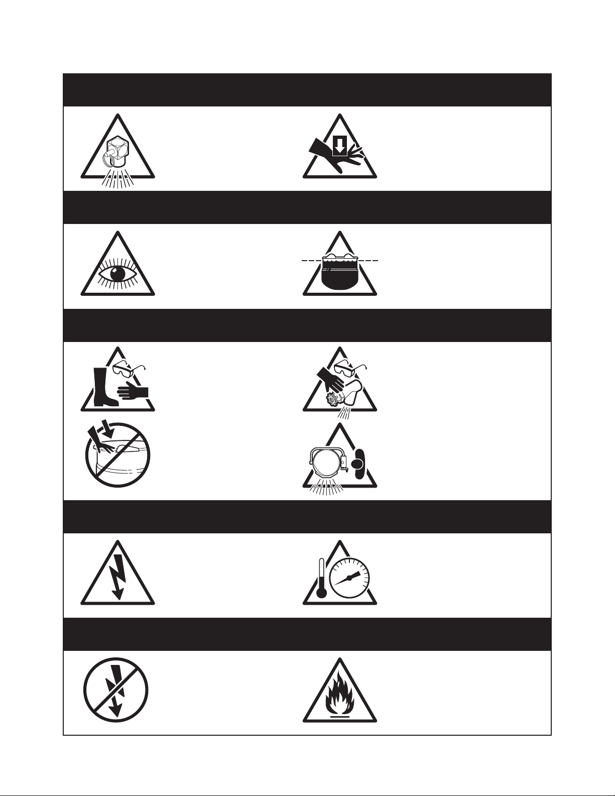
For your safety
DANGER
Keep clear of pressure
relief discharge.
IMPORTANT
Inspect unit daily for
proper operation.
CAUTION
Surfaces may be
extremely hot! Use
protective equipment.
Keep hands away from
moving parts and pinch points.
Do not fill kettle above
recommended level
marked on outside of kettle.
Wear protective equipment
when discharging hot product.
Do not lean on or place
objects on kettle lip.
SERVICING
Shut off power at main
fuse disconnect prior
to servicing.
GAS APPLIANCES
Do not attempt to operate
this appliance during a
power failure.
Stand clear of product
discharge path when
discharging hot product.
Ensure kettle is at room
0
temperature and pressure
gauge is showing zero or less
prior to removing any fittings.
Keep appliance and area free
and clear of combustibles.

GENERAL
Installation of the kettle must be accomplished by
qualified electrical installation personnel working
to all applicable local and national codes.
Improper installation of product could cause injury
or damage.
This equipment is built to comply with applicable
standards for manufacturers. Included among
those approval agencies are: UL, NSF, ASME/Ntl.
Bd., CSA, CGA, ETL, and others. Many local
codes exist, and it is the responsibility of the
owner/installer to comply with these codes.
Note: Maximum voltage for LVD (low volt
directive for Europe) to be 440 volts for CE
marked appliances.
INSPECTION
Before unpacking visually inspect the unit for
evidence of damage during shipping.
If damage is noticed, do not unpack the unit, follow
Shipping Damage Instructions shown below.
SHIPPING DAMAGE
INSTRUCTIONS
If shipping damage to the unit is discovered or
suspected, observe the following guidelines in
preparing a shipping damage claim.
1. Write down a description of the damage or the
reason for suspecting damage as soon as it is
discovered. This will help in filling out the claim
forms later.
2. As soon as damage is discovered or
suspected, notify the carrier that delivered the
shipment.
3. Arrange for the carrier's representative to
examine the damage.
4. Fill out all carrier claims forms and have the
examining carrier sign and date each form.
INSTALLATION
The first installation step is to refer to the
Specification Sheets or Specification Drawings for
detailed clearance requirements of the kettle.
Next, carefully cut open the shipping carton for
easy removal of the kettle.
ASSEMBLY
Table-top models (12 gallon) must be positioned on
a firm, level stand, or existing counter top, and
bolted in place. These models are supplied with four
threaded mounting bushings welded to the
underside of the base. An optional support stand
with level adjustable legs is available. Once the kettle
is secure, screw tilt handle into the threaded hole
provided at the right side of kettle.
Floor Type Leg Mount Models (20 gallon)
Position on a firm, level surface, and bolt flanged
feet in place. Once the kettle is secure, screw tilt
handle into the threaded hole provided at the right
of kettle.
ELECTRICAL
ENSURE THE ELECTRICAL SUPPLY MATCHES
THE KETTLE'S REQUIREMENTS AS STATED
ON THE RATING LABEL.
This kettle is built to comply with applicable
standards of manufacturers. Included among
these approval agencies are UL, NSF, ASME/Ntl.
Bd., CSA, ETL, and others. Many local codes
exist, and it is the responsibility of the owner and
installer to comply with these codes.
The electrical supply must match the power
requirements specified on the kettle’s rating plate.
The copper wiring must be adequate to carry the
required current at the rated voltage.
Note: Maximum voltage for LVD (low volt
directive for Europe) to be 440 volts for CE
marked appliances.
INSTALLATION
WIRE CONNECTION
If unit does not have cord and plug option, remove
the screw at the rear of the console cover and
remove the cover. A wiring diagram is affixed to
the underside of the cover. Feed permanent
copper wiring through the cut-out in the rear or
bottom of the console, and fasten to the three
connection terminal block, which is mounted on
the top of the console’s control panel. Be sure to
connect the ground wire to the separate ground
terminal connector (ground lug). Replace console
cover and secure it with the screw.
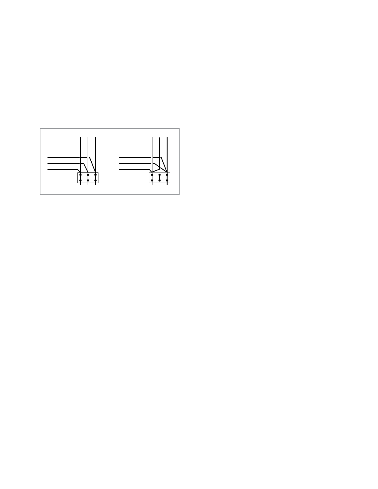
The kettle is wired for 3-phase operation at the
factory. For single phase operation, rewire the
terminal block to that shown in the above diagram.
WATER
The sealed jacket of the electric kettle is
precharged with the correct amount of a waterbased formula, and therefore, no water connection
is required to the kettle jacket. The kettle can be
equipped with optional hot and cold water taps,
the taps require 1/2" copper tubing as supply
lines.
INSTALLATION CHECKS
Although the kettle has been thoroughly tested
before leaving the factory, the installer is responsible
for ensuring the proper operation of kettle once
installed.
Performance Checks
1. Supply power to the kettle by placing the fused
disconnect switch to the "ON" position.
2. Before turning the kettle on, read the
vacuum/pressure gauge. The gauge's needle
should be in the green zone.
3. Place the kettle's power ON/OFF switch to the
"ON" position.
4. Turn the temperature control knob to "1" (Min.).
The green LED light should remain lit, indicating
the burner is lit, until the set temperature is
reached (124°F/50°C). Then the green light will
cycle on and off, indicating the element is
cycling on and off to maintain temperature.
5. Tilt the kettle forward. After a few seconds the
red "LOW WATER" light should be lit when the
kettle is in a tilted position. This light indicates
that the element has automatically been shut off
by the kettle's safety circuit. This is a normal
condition when the kettle is in a tilted position.
6. Raise the kettle to the upright position. The red
"low water" light should go out when the kettle is
upright.
7. Turn the temperature control knob to "10" (Max.)
and allow the kettle to preheat. The green light
should remain on until the set temperature
(260°F/127°C) is reached. Then the green light
will cycle ON and OFF, indicating the element is
cycling ON and OFF to maintain temperature. Fill
the kettle with cold water to the steam jacket’s
welded seam.
8. When all testing is complete, empty the kettle
and place the power ON/OFF switch in the
“OFF” position.
CLEANING
After installation the kettle must be thoroughly
cleaned and sanitized prior to cooking.
RED
YELLOW
BLACK
BLACK
BLUE
RED
L1 L2 L3
THREE
PHASE
RED
YELLOW
BLACK
BLACK
BLUE
RED
L1 L2
SINGLE
PHASE
OPERATING INSTRUCTIONS
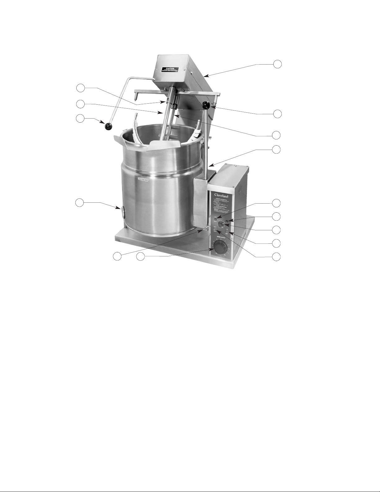
General Parts Drawing
ITEM # DESCRIPTION FUNCTION
1. On-Off Toggle Switch Controls electrical power to kettle.
2. Solid State Temperature This control allows the operator to adjust the kettle temperature in
Control Knob increments from 1 (Min.) to 10 (Max.).
3. Heat Indicator Light (Green)
When lit, indicates that the kettle burner is on. Cycles ON-OFF with burner.
4. Low Water Indicator Light (Red) When lit, indicates that the kettle is low on water and will not operate
in this condition. This will also light when the kettle is tilted.
5. Vacuum/Pressure Gauge Indicates steam pressure in PSI inside steam jacket as well as
vacuum in inches of mercury.
6. Pressure Relief Valve This valve is used to vent the kettle and in the unlikely event there is
an excess steam build-up in the jacket, this valve opens automatically
to relieve this pressure.
7. Kettle Tilt Handle Used for tilting the kettle.
8. Marine Lock Prevents unit from accidental tilting.
9. Agitator Speed Control Knob This control allows the operator to select agitator speed increments
from Min. to Max.
10. Mixer Start Switch Starts mixing action.
11. Mixer Bridge Encloses agitator motors.
12. Mixer Bridge Tilt Handle Used for tilting mixer bridge.
13. Main Agitator Arm Provides most of the product movement.
14. Secondary Agitator Arm Provides reverse agitation and product lift in kettle.
15. Bayonet Mounts for Agitator Arms Allows removal of main and secondary agitator arms without tools.
10
9
5
1
2
3
4
6
8
12
7
11
13
15
14
OPERATING THE KETTLE
DO NOT LEAN ON OR PLACE OBJECTS ON
KETTLE LIP. SERIOUS INJURY COULD RESULT
IF KETTLE TIPPED OVER, SPILLING HOT
CONTENTS.
1. Before turning kettle on, read the
Vacuum/Pressure Gauge (5). The gauges
needle should be in the green zone. Once
heated, the kettle's normal maximum
operating pressure is approximately 10 -12 psi,
while cooking a water base product.
2. Ensure that the electrical service to the kettle
is turned on at the fused disconnect switch.
3. Place the kettle's On-Off Toggle Switch (1) to
the "ON" position.
Temperature Range Chart
4. Preheat the kettle by turning the Solid State
Temperature Control Knob (2) to the desired
temperature setting (see above "Temperature
Range Chart"). The Heat Indicator Light
(Green) (3) will remain lit, indicating the
burner is lit, until the temperature setting is
reached. When the green light goes off, the
heaters are off, and preheating is complete.
NOTE: When cooking egg and milk products, the
kettle should not be preheated, as products of this
nature adhere to hot cooking surfaces. These
types of food should be placed in the kettle before
heating is begun.
5. Place food product into the kettle. The Heat
Indicator Light (Green) (3) will cycle on and
off indicating the elements are cycling on and
off to maintain the set temperature.
NOTE: Do not fill kettle above recommended
level marked on outside of kettle.
NOTE: The Low Water Indicator Light (Red) (4)
should not be lit when kettle is in the upright
position during kettle operation. This light indicates
that the elements have been automatically shut off
by the kettle's safety circuit. It is, however, normal
for the red light to come on when the kettle is in a
tilted position.
6. When cooking is completed place On-Off
Toggle Switch (1) to the "OFF' position.
7. Pour the contents of the kettle into an
appropriate container by tilting the kettle
forward. Care should be taken to pour slowly
enough to avoid splashing off the product.
NOTE: As with cleaning food soil from any
cookware, an important part of kettle cleaning is to
prevent food from drying on. For this reason, cleaning
should be completed immediately after cooked foods
are removed.
APPROXIMATE BOILING TIMES
The accompanying chart shows approximate
times required for electric kettles of various
capacities to boil water. The temperature control
knob must be set at “10” (Max.) throughout the
heat-up period. Water will boil about 1/3 faster if
the kettle is filled only to the outer steam jacket’s
welded seam. resulting in a kettle filled to 2/3
capacity.
Approximate Boiling Times
MIXING
1. Turn Mixer Start Switch (10) to ON.
2. Turn Agitator Speed Control Knob (9) until
desired speed is achieved.
Temperature Approximate
Control Product Temperature
Setting °F °C
1. (Min.) 130 54
2. 145 63
3. 160 71
4. 170 77
5. 185 85
6. 195 91
7. 210 99
8. 230 110
9. 245 118
10. (Max.) 260 127
NOTE: Certain combinations of ingredients will
result in temperature variations
Kettle Capacity Minutes
12 gallon/45 litre 25
20 gallon/80 litre 40
MARINE LOCK
Your unit is equipped with a
marine lock to prevent
accidental tilting. The following
procedure should be used to tilt
the kettle.
1. Grasp the tilt handle.
2. Hold the latch down to unlock tilting mechanism.
3. Pull the handle to tilt kettle.
4. To lock, return the kettle to its upright position
and push handle back.
NOTE: Inspect lock daily to ensure it is free
moving and does not bind or stick. Clean lock
if necessary.
LATCH
MARINE LOCK
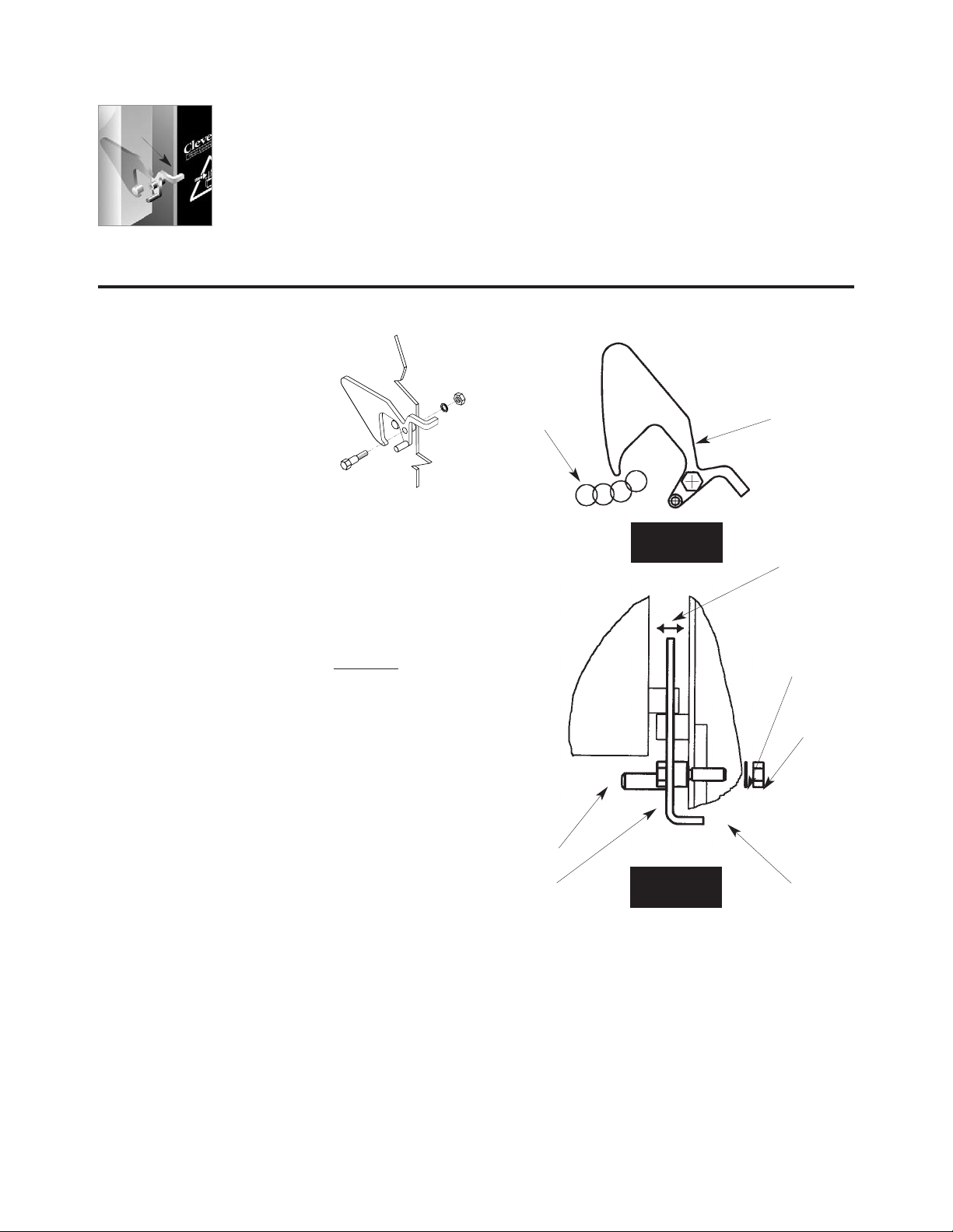
TESTING
PROCEDURE
1. Check that lock clears
stop pin on side box
without rubbing when
kettle is tilted (Figure A).
2. Check side to side play. Lock should remain
fully over stop pin when pushed to it's
maximum side to side play (Figure B).
3. Check that the kettle when pushed fully
upright moves the lock to a closed position.
To check this:
A/ Hold the latch firmly in the unlocked
position while tilting the kettle back to an
upright position.
B/ The kettle sidebox will force the lock into a
new position.
C/ Hold the lock in this position and try to tilt
the kettle forward. The latch should prevent
the kettle from tilting.
4. Check shoulder bolt is firmly seated against
console body.
5. Check on inside of console box that shoulder
bolt locknut is secure.
Side Box
Lockwasher
Locknut
Shoulder Bolt
Console
Figure B
(Top View)
Side to Side Play
Stop Pin on
Sidebox
Marine Lock
(Latch)
Figure A
(Side View)
CARE AND CLEANING
Cooking equipment must be cleaned regularly to
maintain its fast, efficient cooking performance and
to ensure its continued safe, reliable operation. The
best time to clean is shortly after each use (allow
unit to cool to a safe temperature).
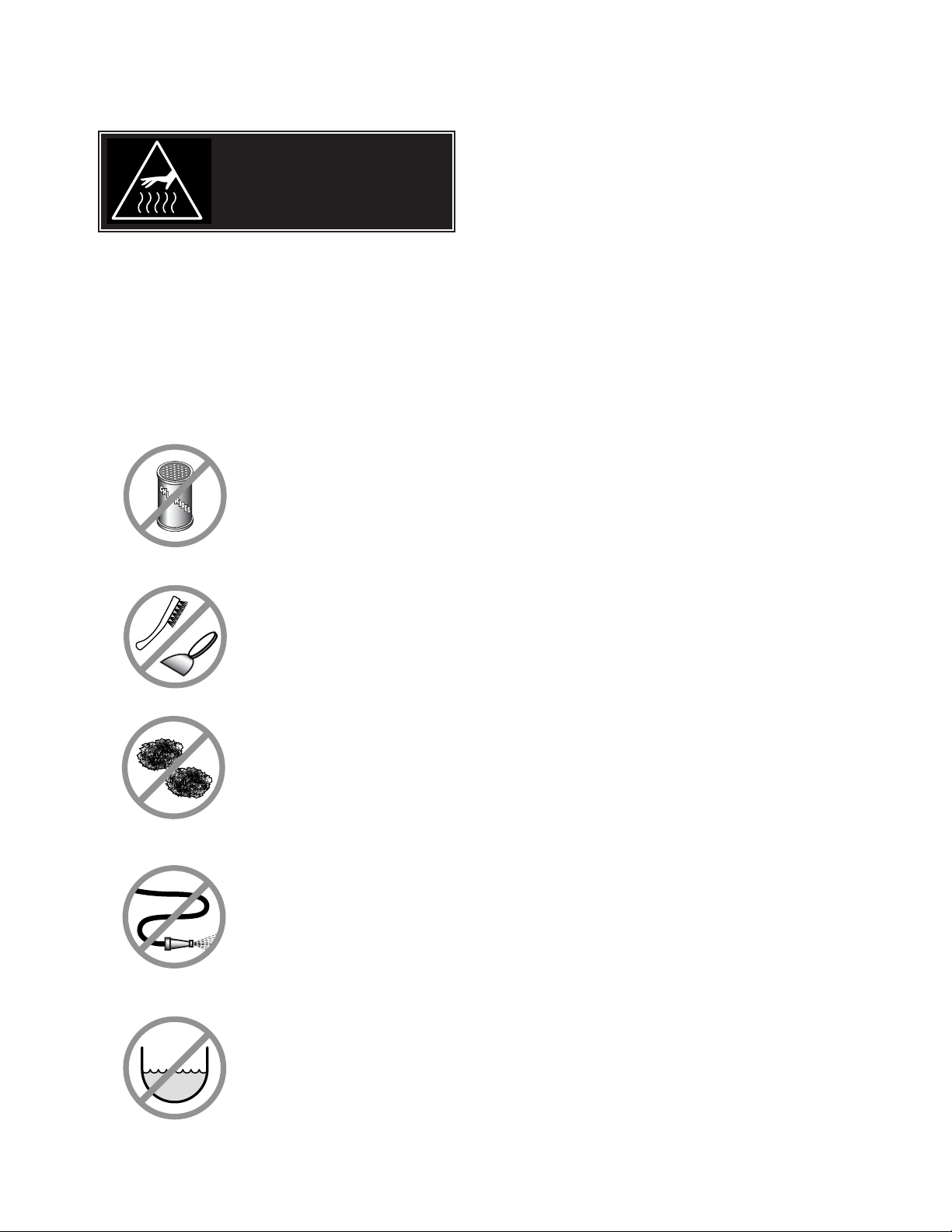
WARNINGS
➩ Do not use detergents or
cleansers that are chloride
based or contain quaternary
salt.
➩ Do not use a metal bristle
brush or scraper.
➩ Steel wool should never be
used for cleaning the stainless
steel.
➩ Unit should never be cleaned
with a high pressure spray
hose.
➩
Do not leave water sitting in unit
when not in use.
Stagnant
Water
High Pressure
Spray Hose
Chloride Cleaners
Steel Pads
Wire Brush &
CLEANING INSTRUCTIONS
CAUTION
SURFACES MAY
BE EXTREMELY HOT!
CLEANING INSTRUCTIONS
1. Turn unit off.
2. Remove drain screen (if applicable). Thoroughly
wash and rinse the screen either in a sink or a
dishwasher.
3. Prepare a warm water and mild detergent solution in
the unit.
4. Remove food soil using a nylon brush.
5. Loosen food which is stuck by allowing it to soak at
a low temperature setting.
6. Drain unit.
7. Rinse interior thoroughly.
8. If the unit is equipped with a Tangent Draw-Off
Valve, clean as follows:
a) Disassemble the draw-off valve first by turning
the valve knob counter-clockwise, then turning
the large hex nut counter-clockwise until the
valve stem is free of the valve body.
b) In a sink, wash and rinse the inside of the valve
body using a nylon brush.
c)
Use a nylon brush to clean tangent draw-off tube.
d) Rinse with fresh water.
e) Reassemble the draw-off valve by reversing the
procedure for disassembly. The valve's hex nut
should be hand tight only.
9. If the unit is equipped with a Butterfly Valve, clean
as follows:
a) Place valve in open position.
b) Wash using a warm water and mild detergent
solution.
c) Remove food deposits using a nylon brush.
d) Rinse with fresh water.
e) Leave valve open when unit is not in use.
10 . Using mild soapy water and a damp sponge, wash
the exterior, rinse, and dry.
NOTES
➩ For more difficult cleaning applications one of the
following can be used: alcohol, baking soda, vinegar,
or a solution of ammonia in water.
➩ Leave the cover off when the kettle is not in use.
➩ For more detailed instructions refer to the Nafem
Stainless Steel Equipment Care and Cleaning manual
(supplied with unit).
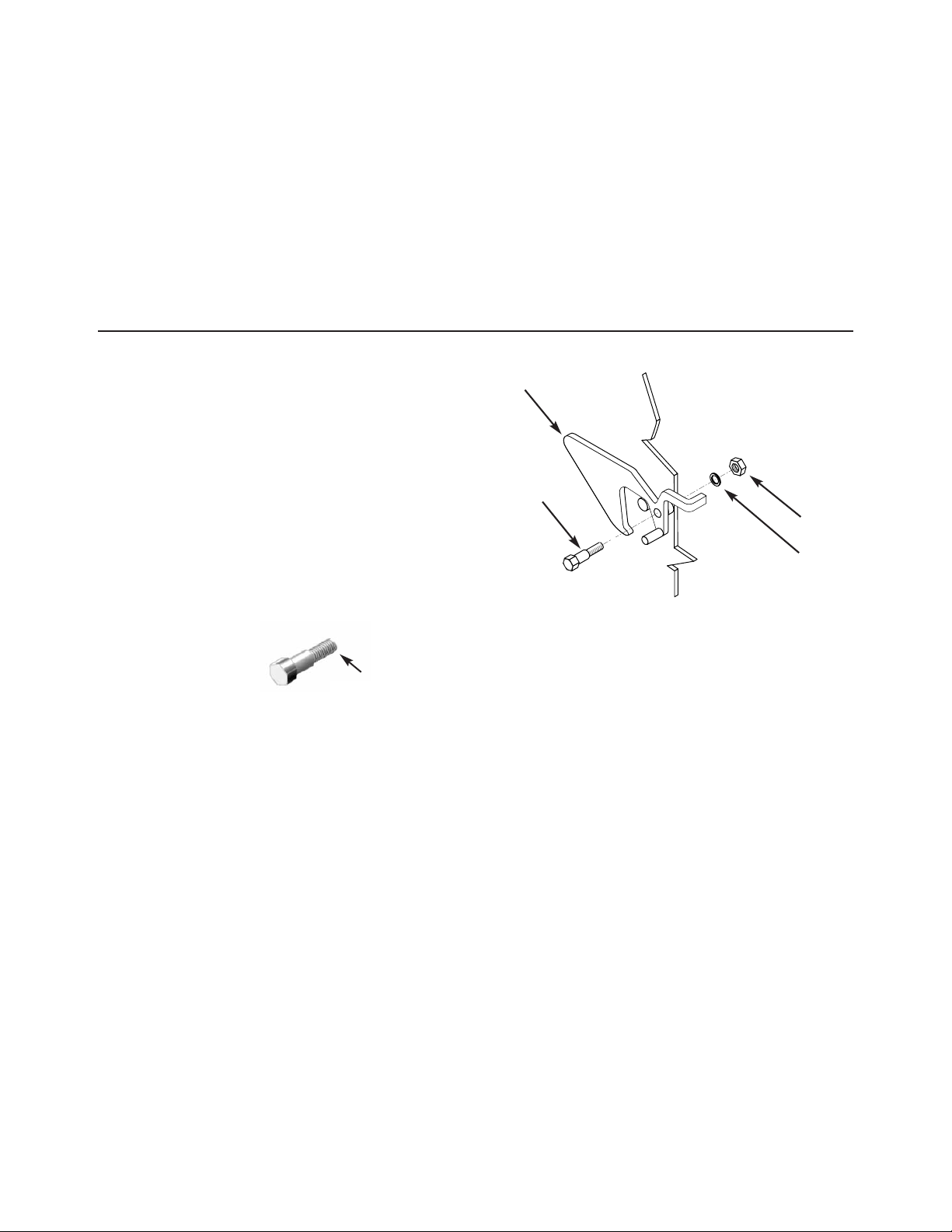
MARINE LOCK
Use a small nylon bristle brush to remove food
and debris from pivot point. If lock is still sticking
have maintenance disassemble and clean pieces
individually and reassemble.Disassembly
1. Disconnect power from kettle.
2. Remove console cover from top of kettle's
console.
3. Remove locknut and lockwasher from inside
console.
4. Remove shoulder bold from latch.
5. Clean all parts.
Re-Assembly
6. Apply locktight to shoulderbolt where
illustrated. Replace shoulder bolt and latch
and tighten firmly.
7. Replace lockwasher and locknut inside the
console and tighten firmly.
8. Test Marine Lock. See Marine Lock Testing
Procedure.
9. Replace console cover.
Latch
Shoulder Bolt
Lockwasher
Locknut
Carefully apply
locktight to the
final two threads.
AGITATOR ASSEMBLY
1. Place the Kettle’s On-Off Toggle Switch (1) to
the "OFF' position.
2. Raise Mixer Bridge (11).
3. Push Main Agitator Arm towards Bayonet
Mount (15), rotate counterclockwise and then
pull out to remove. Repeat process for
Secondary Agitator Arm (14).
4. Scraper blades can be removed by sliding
them up the arm and rotating until free.
5. Clean all parts.
 Loading...