

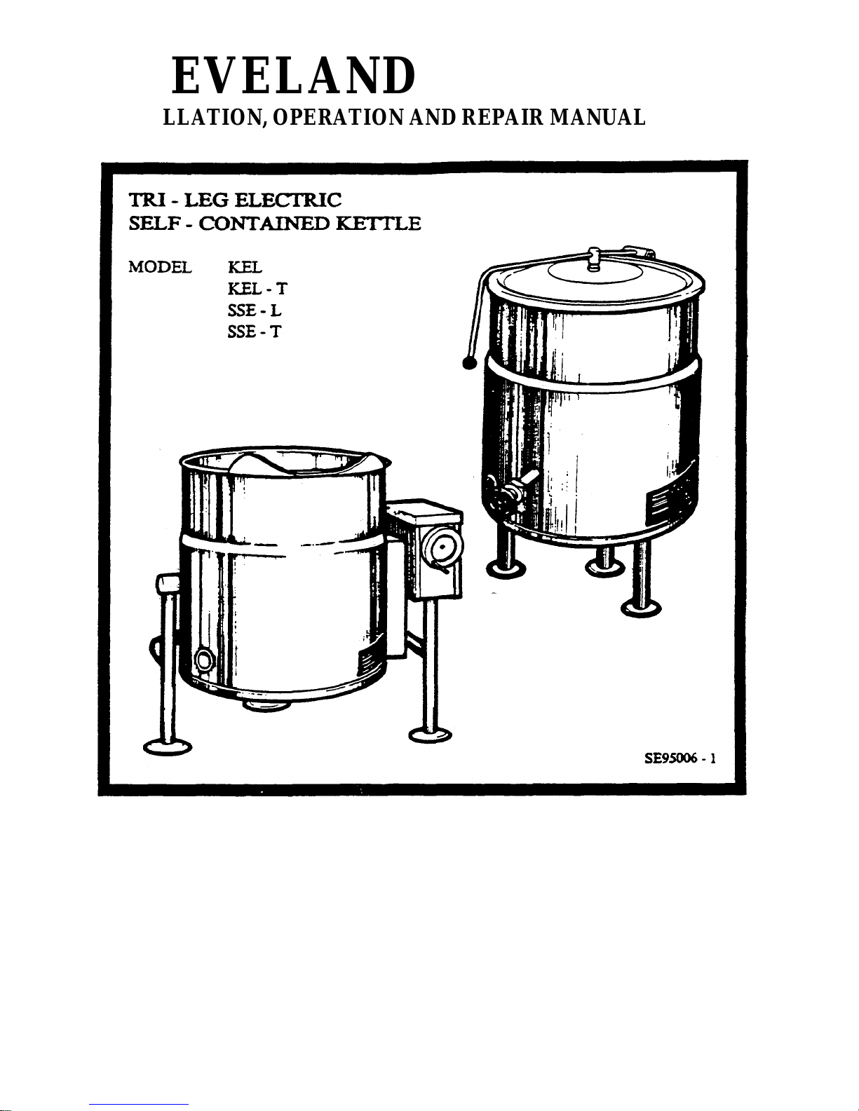
Cleveland SSE-25-T, KEL-40-T, SSE-40-L, SSE-40-T, KEL-60 Installation, Operation And Repair Manual
...Page 1
CLEVELAND
INSTALLATION, OPERATION AND REPAIR MANUAL
CLEVELAND RANGE INC.
1333 East 179th St.
Cleveland. Ohio
U.S.A. 44110
(216)481-4900
9209 REV:1 213-01CC
KET-06
Page 2
CLEVELAND
INSTALLATION, OPERATION AND MAINTENANCE
INSTRUCTIONS FOR
ELECTRIC SELF-CONTAINED KETTLES
FLOOR MODELS
KEL-25
KEL-40
KEL-60
KEL-80
KEL-100
KEL-25-T
KEL-40-T
KEL-60-T
KEL-80-T
KEL-100-T
SSE -25-L
SSE -40-L
SSE -60-L
SSE -80-L
SSE -100-L
SSE -25-T
SSE -40-T
SSE -60-T
SSE -80-T
SSE -100-T
RETAIN THIS MANUAL FOR YOUR REFERENCE
Page 3
INSTALLATION INSTRUCTIONS
WARNING:
Installation of this kettle must be accompanied
by qualified electrical installation personnel
working to all applicable local and national
codes. Improper installation of this product could
cause injury or damage.
This equipment is built to comply with applicable
standards of manufacturers. Included among
these approval agencies are UL,
NSF,ASME/Ntl. Bd., CSA,ETL,and others.
Many local codes exist, and it is the
responsibility of the owner and installer to
comply with these codes.
INSPECTION
Before unpacking visually inspect the unit for
evidence of damage during shipping. If damage is
noticed, do not unpack the unit, follow shipping
damage instructions.
4. Fill out all carrier claims forms and have
the examining carrier sign and date each
form.
INSTALLATION
The first installation step is to refer to the
specification sheet for the clearance
requirements, in order to determine the location of
the kettle. Next, carefully cut open the shipping
carton for easy removal of the kettle.
SHIPPING DAMAGE INSTRUCTIONS
If shipping damage to the unit is discovered or
suspected, observe the following guidelines in
preparing a shipping damage claim.
1. Write down a description of the damage
or the reason for suspecting damage as
soon as it is discovered. This will help in
filling out the claim for ms later.
2. As soon as damage is discovered or
suspected, notify the carrier that
delivered the shipment.
3. Arrange for the carrier's representative
to examine the damage.
ASSEMBLY
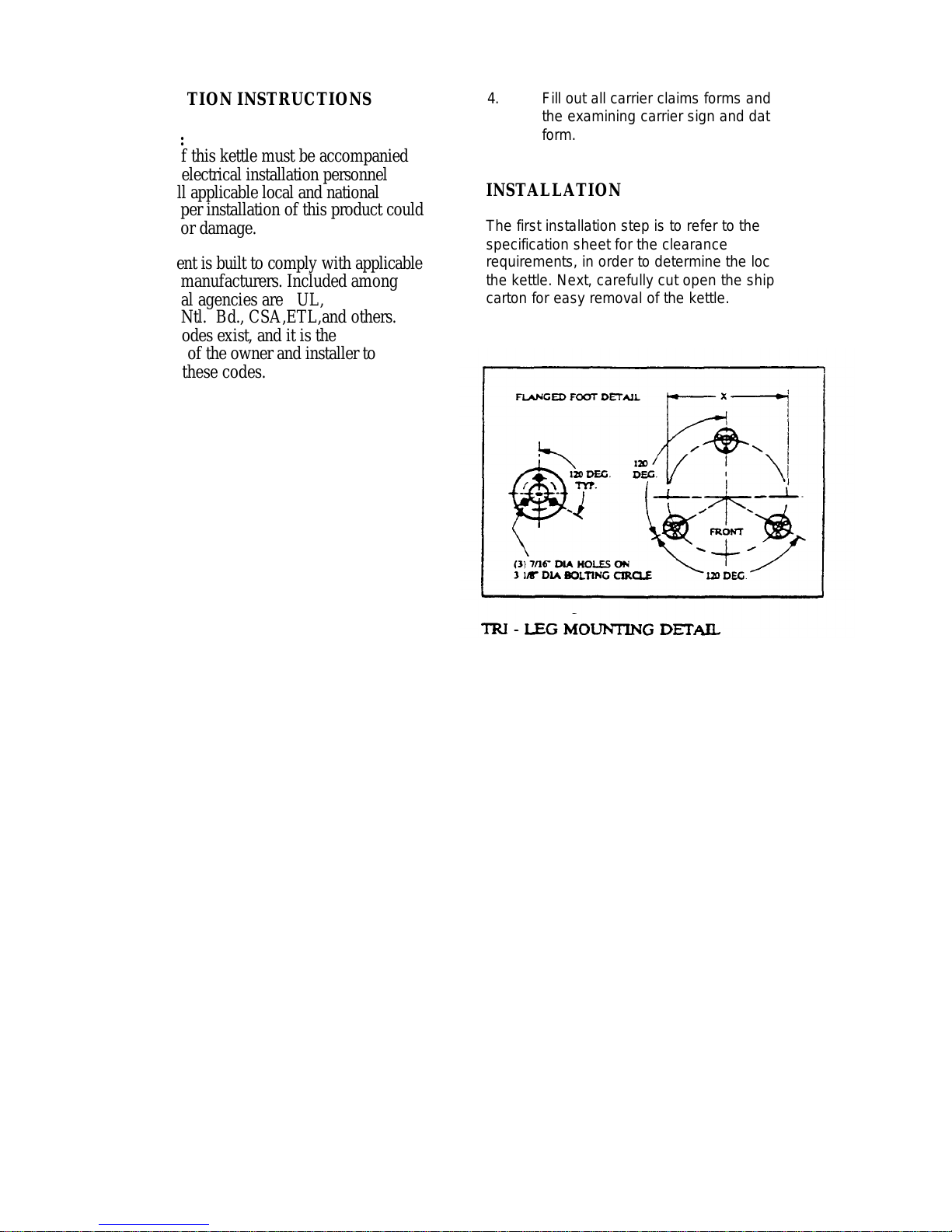
Position the kettle in its' permanent location, and
level the kettle by turning the adjustable flanged
feet. Once positioned and leveled, permanently
secure the kettle's flanged feet to the floor using
5/16 inch lag bolts and floor anchors (supplied by
the installer). There are three bolts required to
secure each of the flanged feet.
1
Page 4
ELECTRIC SERVICE CONNECTION
TILTING MODELS
Install in accordance with local codes and/or the
National Electric Code ANSI/NFPA No. 70-1990
(USA) or the Canadian Electric Code CSA
Standard C22.1 (Canada). A separate fused
disconnect switch must be supplied and installed.
The kettle must be electrically grounded by the
installer.
The electric supply must match the power
requirements specified on the kettle's rating plate.
The copper wiring must be adequate to carry the
required current at the rated voltage. Refer to
specifi cation sheet for all electrical specifications.
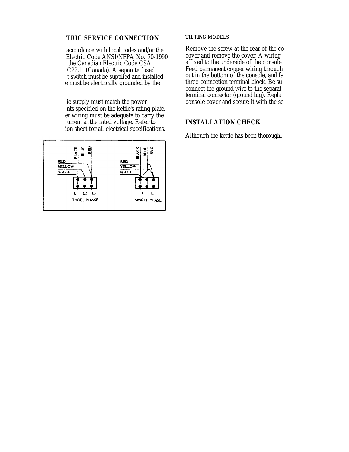
The kettle is wired for 3-phase operation at the
factory. For single phase operation, rewire the
terminal block to that shown in the accompanying
diagram.
Remove the screw at the rear of the console
cover and remove the cover. A wiring diagram is
affixed to the underside of the console cover.
Feed permanent copper wiring through the cutout in the bottom of the console, and fasten to the
three-connection terminal block. Be sure to
connect the ground wire to the separate ground
terminal connector (ground lug). Replace the
console cover and secure it with the screw.
INSTALLATION CHECK
Although the kettle has been thoroughly tested
before leaving the factory, the installer is
responsible for ensuring the proper operation of
the kettle once installed.
1. Supply power to the kettle by placing the
fused disconnect switch to the "on"
position.
2. Read the vacuum/pressure gauge to
ensure that the needle rests in the green
zone(at room temperature). If the needle
is in the "vent air" zone, refer to the
"Kettle Venting Instructions".
3. Place the kettle's power on/off switch to
the "on" position.
ELECTRICAL CONNECTION
STATIONARY MODELS
Remove the screws securing the dome -shaped
service cover underneath the kettle and remove
the cover. A wiring diagram is affixed to the
inside of cover. Fasten permanent copper wiring
to the three-connection terminal block. Be sure to
connect ground wire to the separate ground
terminal connector (ground lug). Slide the cover's
slot over the wiring and secure the cover to kettle
with the screws.
4. Turn the temperature control knob to
"min". The green LED light should
remain lit, indicating the heater elements
are energized, until the set temperature
(124°F/50°C) is reached. Then the green
light will cycle on and off with the
thermistor (solid state control).
2
Page 5
5. If the kettle is a tilting model, tilt the
kettle forward. The red "low water" light
should be lit when the kettle is in a tilted
position. This light indicates that the
heater elements are not submerged in
water, and they have automatically been
shut off by the kettle's safety circuit. This
is a normal conditon when kettle is in a
tilted position.
6 Lower the kettle to the upright position.
The red "low water" light should go out
when the kettle is upright. If the red light
remains lit in the upright position, it
indicates a low water condition, and water
must be added to reservoir before the
kettle can be operated. Refer to the
"Reservoir Fill Procedures", on the kettle's
label, for details.
7. Turn the temperature control knob to
"max." and allow the kettle to preheat.
The green light should remain on until the
set temperature is reached (260°F/127°
C), then cycle on and off with the
thermistor. Fill the kettle with cold water
to the steam jacket's welded seam. Refer
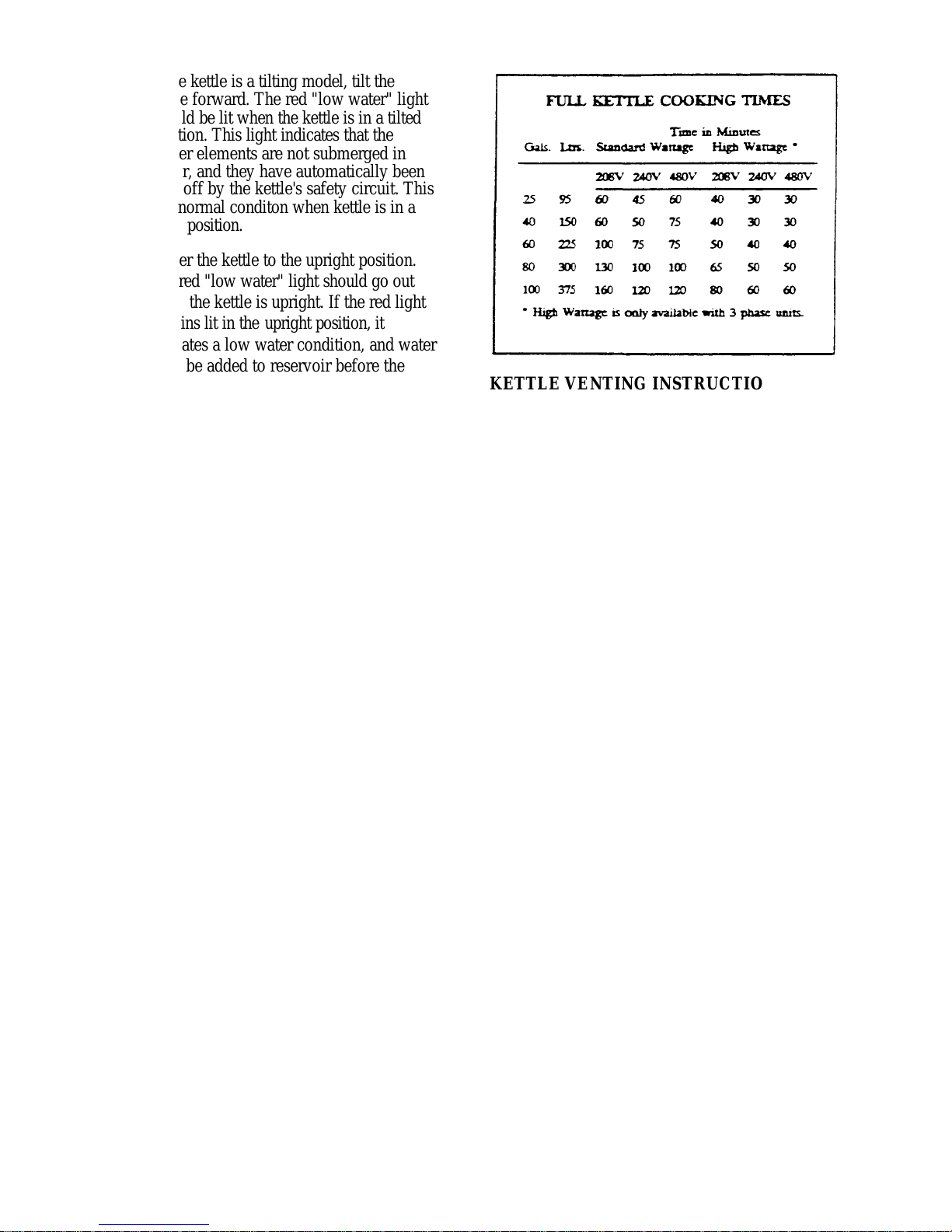
to the chart below for the time required to
bring the water to a boil.
8. When all testing is complete, empty the
kettle and place the power on/off switch
in the "off" position.
The accompanying chart shows
approximate times required for electric
kettles of various capacities to boil water.
Temperature control knob must be set at
"Max." throughout the heatup period.
Water will boil about 1/3 faster if the
kettle is filled only to the outer steam
jacket's welded seam, resulting in a kettle
filled to 2/3 capacity.
KETTLE VE NTING INSTRUCTIONS
If the vacuum/pressure gauge reading is in the
"vent air" zone, it means that the air has entered
the steam/water jacket, resulting in little or no
vacuum. Air inside the jacket will act as an
insulator therefore reducing kettle efficiency. To
remedy this situation, the following venting
procedures should be followed:
1. With the temperature control knob set at
number 6 or 7, heat the empty kettle
until the vacuum/pressure gauge
indicates 5-10 psi.
2. Release steam and air from the
steam/water jacket by loosening, one -half
turn, the 7/16 inch chrome-plated brass
venting valve nut (located at the rear of
the kettle) for 10-15 seconds.
3. Tighten the vent valve nut, being careful
not to overtighten.
The kettle's steam/water jacket should now be
free of air. At room temperature, the pressure
gauge needle should rest in the green zone,
indicating a vacuum in the kettle's jacket.
3
Page 6
To check the gauge for proper vacuum after
venting, the temperature can be quickly reduced
by filling the kettle with cold water.
If the kettle will not hold a vacuum, have a
qualified service technician test for leaks at the
vent valve, the safety valve, the probe, and the
vacuum/pressure gauge fittings. We suggest
mixing a 50/50 solution of liquid detergent and
water while heating the kettle to at least 5 psi
pressure. Then, shut off power to the kettle at the
fused disconnect switch.
The soapy solution should be applied to the
suspected area while the gauge shows at least 5
psi pressure. Any bubbles which appear will
indicate a leak.
WARNING: The fused disconnect
switch must be off before removing the
kettle's bottom cover, which exposes
dangerous high voltage.
RESERVOIR FILL PROCEDURES
The reservoir's water level must be maintained at
the proper level to submerge the heater elements.
Under normal operating conditions, the sealed
water reservoir should never require the addition
of water. If the red "low water" light comes on
during use (while the kettle is in an upright
position), the water level has reached a critically
low level. The low water protection control has
automatically shut off the heater elements. The
following procedure must be completed before
further use:
NOTE: Have a qualified service
technician locate and repair the
leakage problem before adding
water to the unit. Ensure that the
red "low water" light is on when
the kettle is upright.
On tilting kettles, it is normal for the red light to
come on when the kettle is in a tilted position, as
the elements are not submerged in water at this
point.
1. Ensure kettle is at room temperature.
2. Shut off power to the kettle at the fused
disconnect switch.
3- Remove the bottom cover (tilting kettles
can be tilted forward for easier access to
the cover). Tilt the kettle back to the
upright position once the cover has been
removed.
4. Unscrew and remove the chrome -plated
brass venting valve nut located on the
back of the ke ttle.
5. Hold the safety valve open while adding
distilled water through the vent hole,
using a funnel. Refer to chart below for
the proper amount required.
6. Place the chrome -plated brass venting
valve nut into the water fill bole and
carefully tighten. Do not overtighten.
Replace bottom cover.
7. Restore power to the kettle at the fused
disconnect switch.
8. The kettle must now be vented. Refer to
the "Kettle Venting Instructions".
CAUTION: Only distilled water
should be used when
adding water to a
partially filled water
reservoir. Local tap water
conditions may cause
kettle damage which is
not covered under
warranty.
4
Page 7
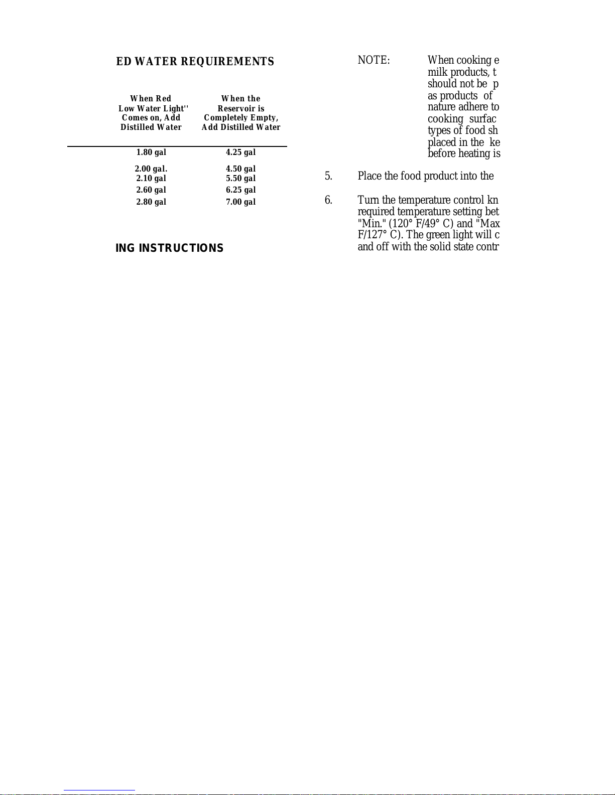
DISTILLED WATER REQUIREMENTS
When Red
When the
Reservoir is
Completely Empty,
"Low Water Light''
Kettle
Capacity
30gaL 1.80 gal 4.25 gal
40 gal
60 gal 2.10 gal 5.50 gal
80 gal 2.60 gal 6.25 gal
100 gal 2.80 gal 7.00 gal
Comes on, Add
Distilled Water
2.00 gal.
Add Distilled Water
4.50 gal
OPERATING INSTRUCTIONS
1. Before turning the kettle on, read the
vacuum/pressure gauge. The gauges needle
should be in the green zone. If the needle
is in the "vent air" zone, refer to the "Kettle
Venting Instructions". Any air that may be
present will increase cooking times. Once
heated, the kettle's normal maximum
operating pressure is approximately 10-12
psi, while cooking a water base product
2. Ensure that the electrical service to the
kettle is turned on at the fused disconnect
switch.
3. Place the kettle's power on/off switch to
the "on" position.
NOTE: When cooking egg and
milk products, the kettle
should not be preheated,
as products of this
nature adhere to hot
cooking surfaces, These
types of food should be
placed in the kettle
before heating is begun.
5. Place the food product into the kettle.
6. Turn the temperature control knob to the
required temperature setting between
"Min." (120° F/49° C) and "Max." (260°
F/127° C). The green light will cycle on
and off with the solid state control,
indicating the heaters are cycling on and
off to maintain the set temperature.
7. The red "low water" light should not be
lit during kettle operation. This light
indicates that the heater elements are not
submerged in water, and they have been
automatically shut off by the kettle's
safely circuit. On tilting kettles, it is
normal for the red light to come on when
the kettle is in a tilted position. However,
the kettle cannot be operated when the
red light remains lit while the kettle is in
the upright position. This indicates a low
water condition, and water must be added
to the reservoir. Refer to the "Reservoir
Fill Procedures " for details.
4. Preheat the kettle by turning the
temperature control knob to the desired
temperature setting (see temperature range
chart). The green light will remain lit,
indicating the heater elements are
energized, until the temperature setting is
reached. When the green light goes off, the
heaters are off, and preheating is complete.
8. When cooking is completed, place the
power on/off switch to the “off” position.
5
Page 8
9. Pour the contents of the kettle into an
appropriate container by opening the
draw-off valve or tilting the kettle
forward. Care should be taken to pour
slowly enough to avoid splashing off the
product.
NOTE: As with cleaning food soil from
any cookware, an important pan of kettle
cleaning is to prevent food from drying
on. For this reason, cleaning should be
completed immediately after cooked
foods are removed. Refer to the "Care
and Cleaning Instructions" for detailed
kettle washing procedures.
WARNING: Do not use chloride base
detergents.
1. Prepare a warm water and mild detergent
solution in the kettle.
2. Remove food soil inside the kettle using
a nylon brush. Do not use a metal bristle
brush, as this may permanently damage
the kettle's stainless steel surface.
3. Loosen food which is stuck to the kettle
by allowing it to soak at a low setting.
4. If the kettle is equipped with a draw-off
valve, it should be cleaned as follows:
TEMPERATURE RANGE CHART
Temperature
Control
Setting
Minimum 120 49
1 130 54
2 145 63
3 160 71
4 170 77
5 185 85
6 195 91
7 210 99
8 230 110
9 245 118
Maximum 260 127
* Approx. Product
Temperature
°F °C
* Certain combinations of ingredients will result in
temperature variations.
a. Remove the drain screen from the
bottom of the kettle. Thoroughly
wash and rinse the screen either
in a sink or a dishwasher, then
replace it into the kettle.
b. Disassemble the draw-off valve
first by turning the valve knob
counter-clockwise, then turning
the large hex nut counterclockwise until the valv e stem is
free of the valve body.
c. In a sink, wash and rinse the
valve stem, hex nut and knob.
Wash and rinse the inside of the
valve body using a nylon brush.
d. Reassemble the draw-off valve by
reversing the procedure for
disassemble. The valve 's hex nut
should be hand tight only.
CARE AND CLEANING
Your kettle must be cleaned regularly to
maintain its fast, efficient cooking
performance, and to ensure its continued safe,
reliable operation.
6
Page 9
5. Rinse kettle interior thoroughly, then
dram the rinse water.
ELECTRIC KETTLE
CALIBRATING PROCEDURE
6. Leave the cover off when the kettle is
not in use.
7. Using mild soapy water and a damp
sponge, wash the exterior of the kettle,
rinse, and dry. Avoid soaking the electric
control panel. Always turn off
equipment power before using water to
wash equipment.
NOTE: For more difficult cleaning
applications one of the following can be
used: alcohol, baking soda, vinegar, or a
solution of ammonia in water. Avoid the
use of chloride cleansers, which may
damage the kettle's stainless steel surface.
WARNING: Steel wool should never be
used for cleaning the cooking chamber of
kettle. Particles of steel wool become
embedded in the cooking surface and
rust, which may corrode the stainless
steel.
WARNING: Never hose down the kettle.
Water seeps into the underside of the
kettle, shorting and burning out the
elements.
1. Insure the unit has a vacuum before you
begin calibrating procedures. If unit
requires venting refer to "KETTLE
VENTING INSTRUCTIONS'' in this
manual.
2. Turn kettle on and set temperature dial to
maximum (10).
3. Allow the unit to cycle twice.
4. Check temperature of the inner kettle
surface with a digital thermometer.
5. Temperature should be 265°F.
6. Using a screw driver adjust temperature
by turning the potentiometer on the black
box. Turn very little. Turn clockwise to
INCREASE, and counter-clockwise to
DECREASE temperature.
7. Allow the unit to cycle twice.
8. Check temperature of the inner kettle
surface with a digital thermometer.
9. Repeat steps 4 through 8 until unit is
calibrated.
MAINTENANCE
This equipment requires very little preventive
maintenance other than daily cleaning. Some
kettles are equipped with handwheel tilting
mechanisms which require periodic preventive
maintenance to assure continued trouble-free
operation. Inspect the worm screw, tilting gears
and bearings occasionally (at least once a year).
Lubricate as required using a high temperature
grease. Remove bottom cover, heat kettle and
test pressure relief valve twice a year.
7
Page 10
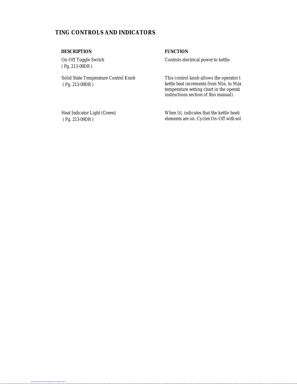
OPERATING CONTROLS AND INDICATORS
ITEM NO. DESCRIPTION FUNCTION
16 On-Off Toggle Switch
( Pg. 213-09DR )
20 Solid State Temperature Control Knob
( Pg. 213-09DR )
17 Heat Indicator Light (Green)
( Pg. 213-09DR )
21 Low Water Indicator Light (Red)
( Pg. 213-09DR )
15 Vacuum/Pressure Gauge
( Pg. 213-09DR )
5 Pressure Relief Valve
( Pg. 213-09DR )
Controls electrical power to kettle.
This control knob allows the operator to select
kettle heat increments from Min. to Max.(see
temperature setting chart in the operating
instructions section of this manual).
When lit, indicates that the kettle heating
elements are on. Cycles On-Off with solid state
contols.
When lit, indicates that the kettle heating
elements have cut out and the unit requires more
water. (See Reservoir Fill Procedure).
Indicates steam pressure in PSI inside the steam
jacket as well as vacuum in inches of mercury.
In the unlikely event that there is an excess steam
build-up in the jacket, this valve opens
automatically to relieve this pressure.
1 Chrome Plated Brass Vent
( Pg. 213-09DR )
NS Service Cover
( Not Shown )
1-7 Daw-Off Valve
( Pg. 600-04TD )
11 Hand Wheel
( Pg. 213-10DR )
16 Power Tilt Control Switch
( Pg. 213-12DR )
This valve is used to vent the kettle if there is
insufficient vacuum as well as for refilling the
kettle with water. (See Venting Instructions and
Reservoir Fill Procedures).
Located underneath the kettle. Remove this cover
for easy access to contactor, kettle control box,
etc.
This valve is used to empty the kettle of either
food products or wash water. It is supplied as
standard equipment on stationary models and is
optional on tilting kettles.
Turn to tilt kettle for pouring.
This switch allows the operator to tilt the kettle
up or down.
8
Page 11
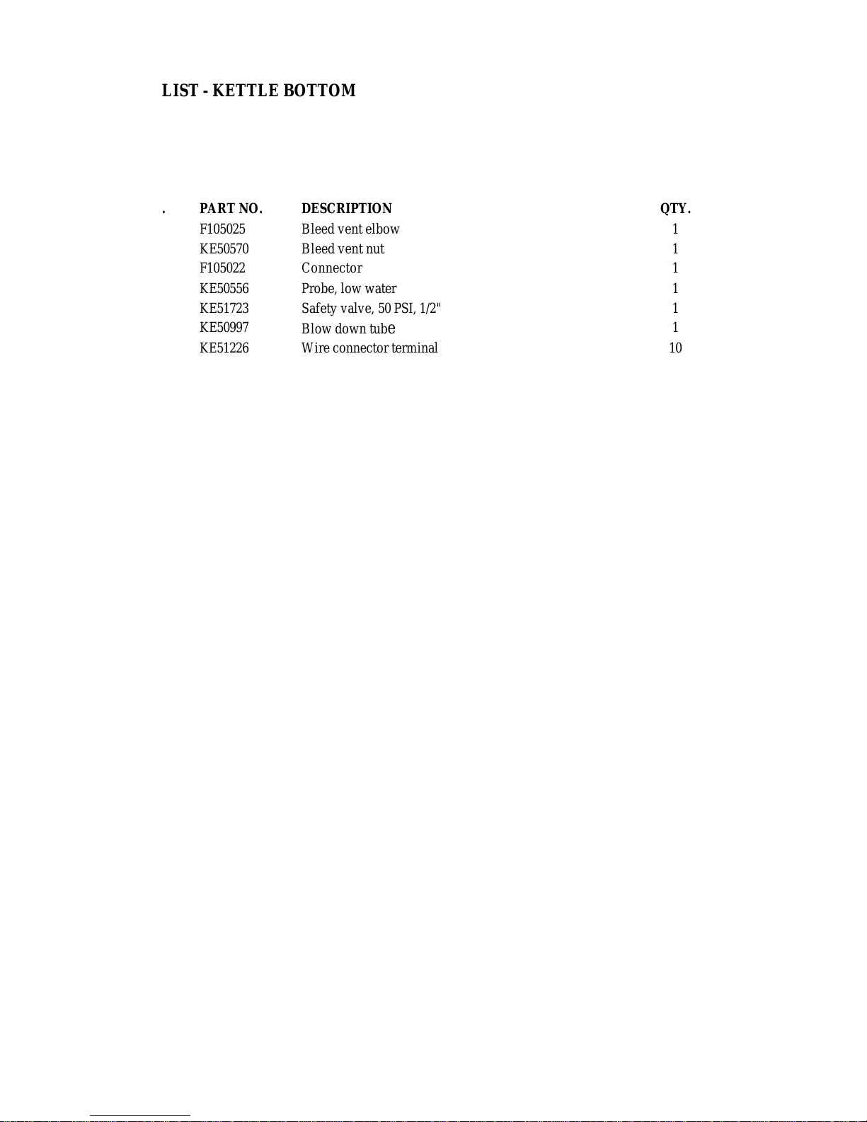
PARTS LIST - KETTLE BOTTOM
ITEM NO. PART NO. DESCRIPTION QTY.
1. F105025 Bleed vent elbow 1
2. KE50570 Bleed vent nut 1
3. F105022 Connector 1
4. KE50556 Probe, low water 1
5. KE51723 Safety valve, 50 PSI, 1/2" 1
6. KE50997
7. KE51226 Wire connector terminal 10
8. KF51225 Edge connector 1
9. KE00458 Solid state control box 1
10. KE50753 Relay, 12 VDC 1
11. KE51322 Contactor, 208/240V, 40 Amp. 2
KE50750 Contactor, 208/240V, 50 Amp. 2
KE50751 Contactor, 208/240V, 60 Amp. 2
12. KE50377 Terminal block section 3
SK50055 Terminal block section 3
13. KE50376 Terminal block end section 1
SK50054 Terminal block end section 1
14. KE50752 Transformer 1
15. KE50429 Pressure gauge 1
16. KE50504 Switch, toggle, SPST 1
17. KE50568
18. SK50062 Rubber boot 1
19. KE50988 Potentiometer 1
20. KE50569 Knob, potentiometer 1
21. KE50567 L.E.D. red 1
22 KE50558 Safety Thermostat (140° C) 1
23. KE00515 Thermistor 1
24. KE51005 Rotary seal 1
Blow down tube
(Standard kettles)
(Special high wattage kettles-6 elements)
(Special high wattage kettles-6 elements)
(Large, white)
(Small, black)
(Large, white)
(Small, black)
L. E. D green
1
1
9
Page 12
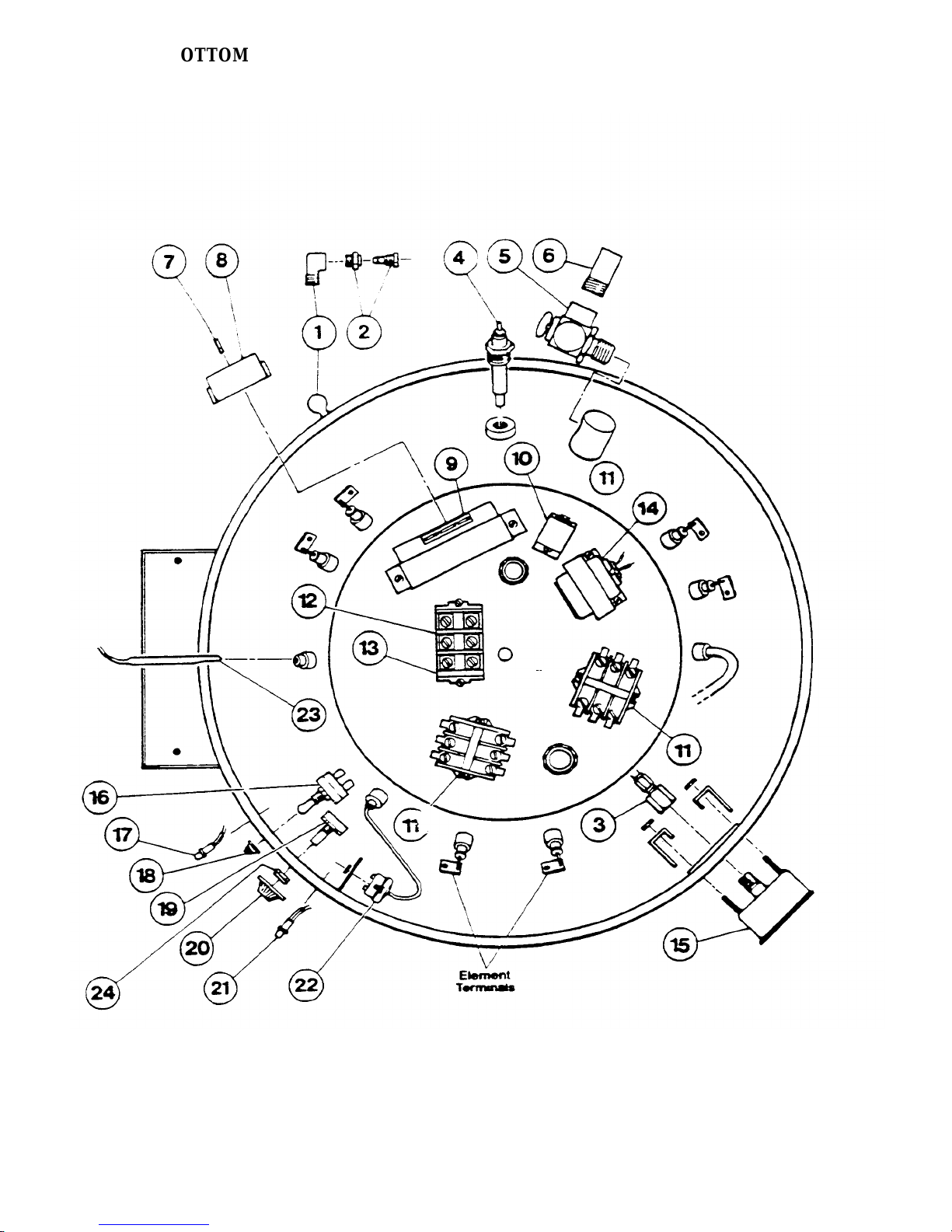
KETTLE BOTTOM
10
Page 13
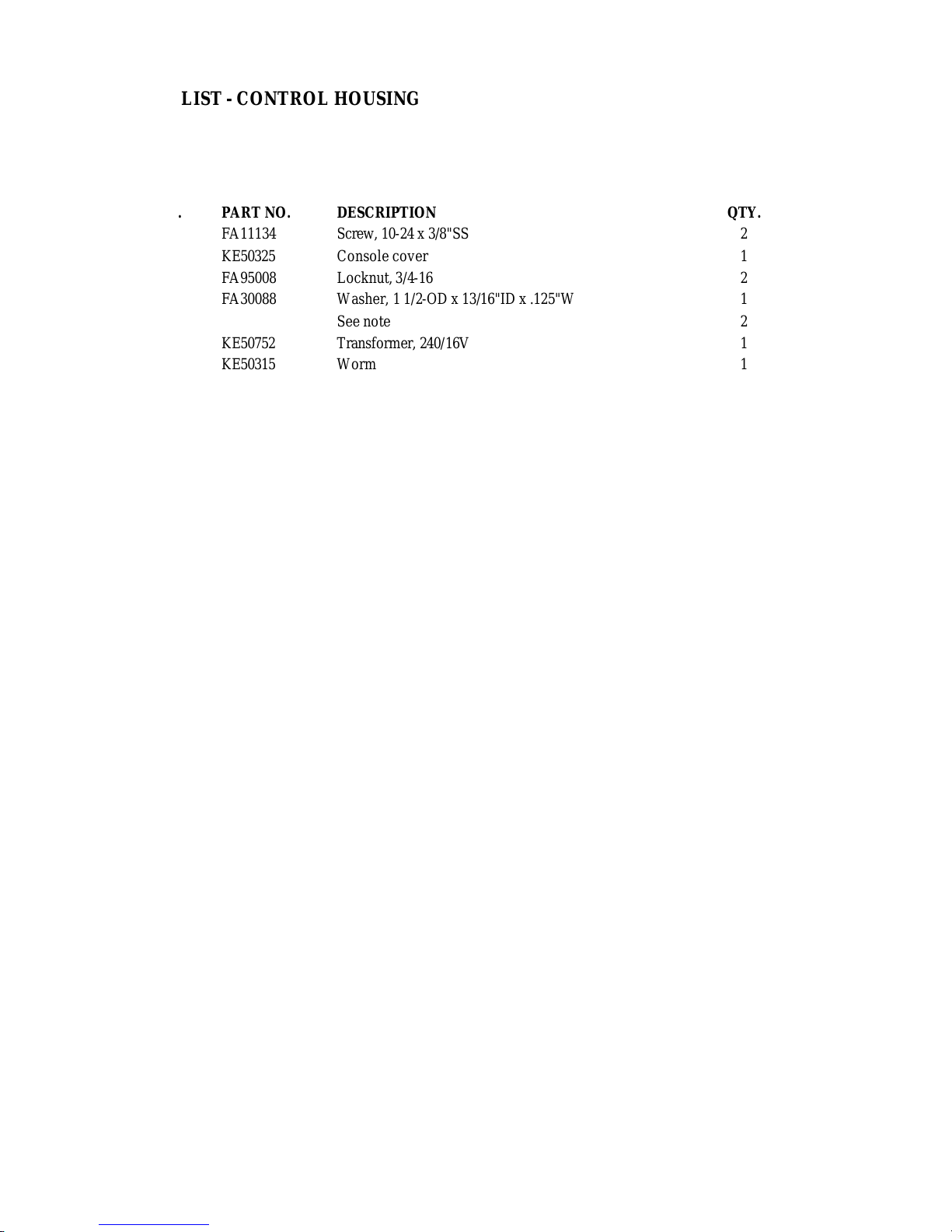
PARTS LIST - CONTROL HOUSING
ITEM NO. PART NO. DESCRIPTION QTY.
1. FA11134 Screw, 10-24 x 3/8"SS 2
2. KE50325 Console cover 1
5. FA95008 Locknut, 3/4 -16 2
4. FA30088 Washer, 1 1/2 -OD x 13/16"ID x .125"W 1
5. See note 2
6. KE50752 Transformer, 240/16V 1
7. KE50315 Worm 1
8. FA95005 Tension pin 1
9. KE50375 Tilt shaft 1
10. FA19186 Set screw, hand wheel 1
11. KE00508 Hand wheel 1
12. FA95007 Retaining ring 2
13. KE00151 Worm gear 1
14. FA95006 Woodruff key 1
15. KE51711 Bearing, roller, trunnion 2
16. KE50377 Terminal block section 3
(Large, white)
SK50055 Terminal block section 3
(Small, black)
17. KE50376 Terminal block end section 1
(Large, white)
SK50054 Terminal block end section 1
(Small, black)
18. SE00034 Bearing assy. 1
19. FA10623 Boll, 5/16-24 x 1 1/2" 1
20. FA20029 Nut, hex, 5/16-24 1
21. KE51891 Washer, 1 1/2"OD x 13/16"ID x .037"W 2
22.-24. SE00036 Thrust bearing assy. 2
22 KE52192 Washer, thrust bearing 4
23. KE52191 Bearing, thrust 2
24. KE52193 Spacer, thrust bearing 2
25. KE51730 Bearing, tilt shaft 1
Note: Please order Item no. 22.-24. - Part no. SE00036
11
Page 14
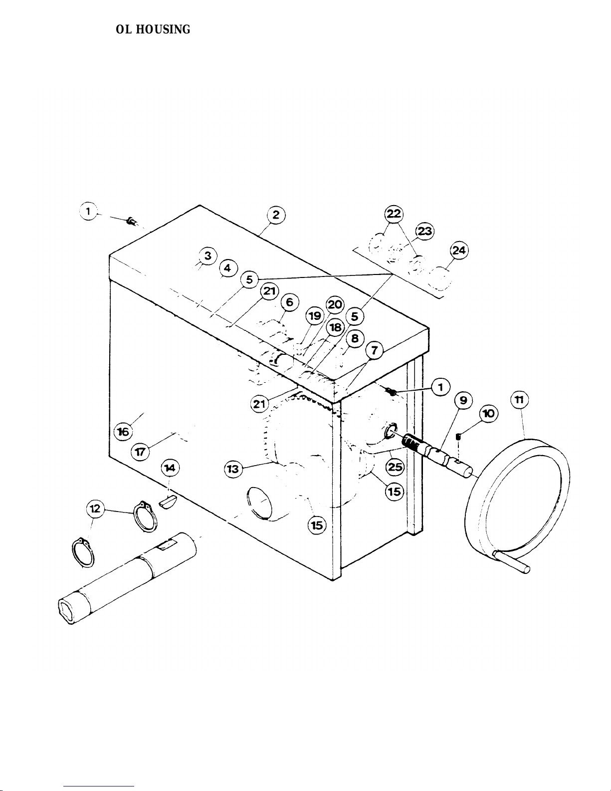
CONTROL HOUSING
12
Page 15
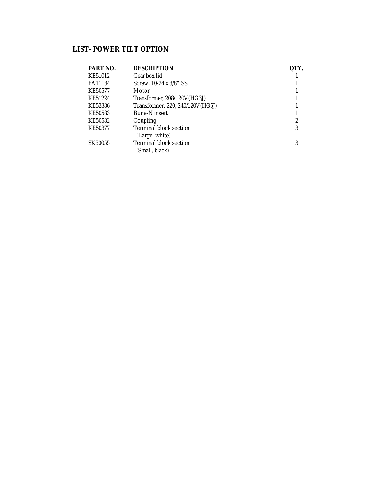
PARTS LIST- POWER TILT OPTION
1.
1 2.
1 3.
1 4.
1
1 5,
1 6.
2 7.
3
3
1
1
2
1
2
1
1
6
1
1
1
1
1
1
1
2
1
1
1
1
4
2
1
1
1
1
2
2
4
2
2
1
1
1
ITEM NO.
8.
9.
10.
11.
12.
13.
14.
15.
16.
17.
18.
19.
20.
21.
22.
23.
24.
25.
26.
27.
28.
29.
30.
31-
32.
33.
34.-36.
34.
35.
36.
37.
38.
39.
PART NO.
KE51012
FA11134
KE50577
KE51224
KE52386
KE50583
KE50582
KE50377
SK50055
KE50376
SK50054
FA95008
FA30088
FA95005
KE50581
KE51011
KE51009
KE51010
KE50752
FA95007
FA95006
KE50580
KE51223
KE51007
FA00012
KE00150
KE50315
KE50441
FA11081
KE51711
KE51731
FA10623
FA20229
SE00034
KE51891
SE00036
KE52192
KE52191
KE52193
FA95037
FA95014
KE50579
DESCRIPTION
Gear box lid
Screw, 10-24 x 3/8" SS
Motor
Transformer, 208/120V(HG3J)
Transformer, 220, 240/120V(HG5J)
Buna-N insert
Coupling
Terminal block section
(Large, white)
Terminal block section
(Small, black)
Terminal block end section
(Large, white)
Terminal block end section
(Small, black)
Locknut, 3/4 -16
Washer, 1 1/2"OD x 13/16"ID x .125"W
See note
Tension pin
Bridge rectifier
Contact section
Square spacer plate
Square actuator
Transformer, 240/16V
Retaining ring
Woodruff key
Water resistant boot
Bottom cover
Micro switch
"0" Ring, circuit breaker
Worm gear
Worm
Tilt shaft
Screw, 8-32 x 1/2", SS
Bearing, roller, trunnion
Bearing, tilt shaft
Bolt, 5/16-24 x 1 1/2"
Nut, hex, 5/16-24
Bearing assembly
Washer, 1 1/2"OD x 13/16"ID x .037"W
Thrust bearing assembly
Washer, thrust bearing
Bearing, thrust
Spacer, thrust bearing
Key, 3/16" x 3/16" x 3/4"
Key, 3/16" x 3/16" x 1"
Circuit breaker, 1 amp
QTY.
Note: Please order item no. 34.-36. - Part no. SE00036
13
Page 16
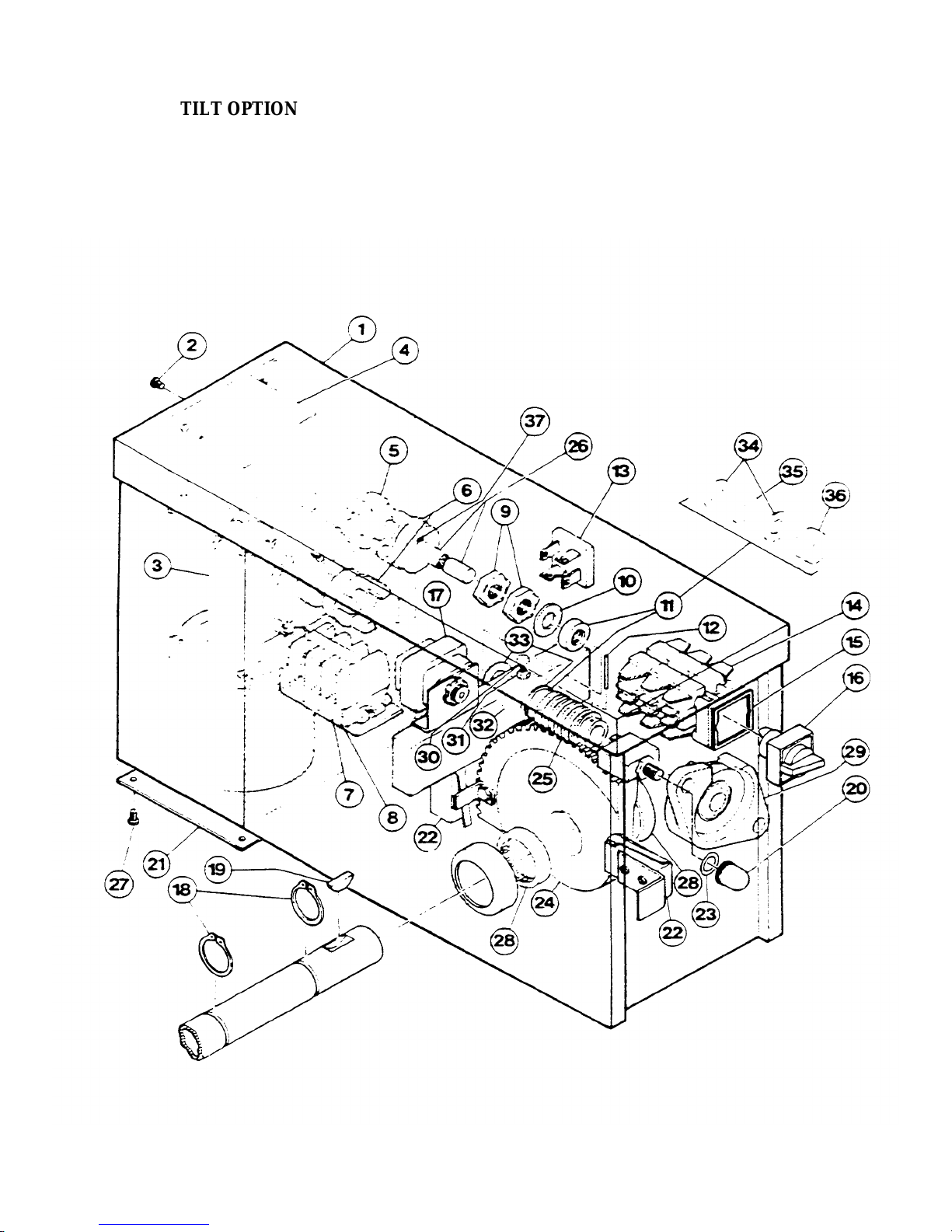
POWER TILT OPTION
14
Page 17
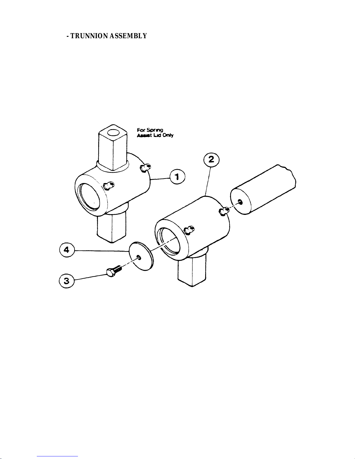
PARTS LIST - TRUNNION ASSEMBLY
ITEM NO. PART NO. DESCRIPTION QTY.
1 KE00354-D Trunnion bearing casting 1
2 KE00351-D Trunnion bearing casting 1
3 KE00349 Bolt, 5/16-18 x 1/2" 1
4 KE50666 Spherical washer 1
15
Page 18
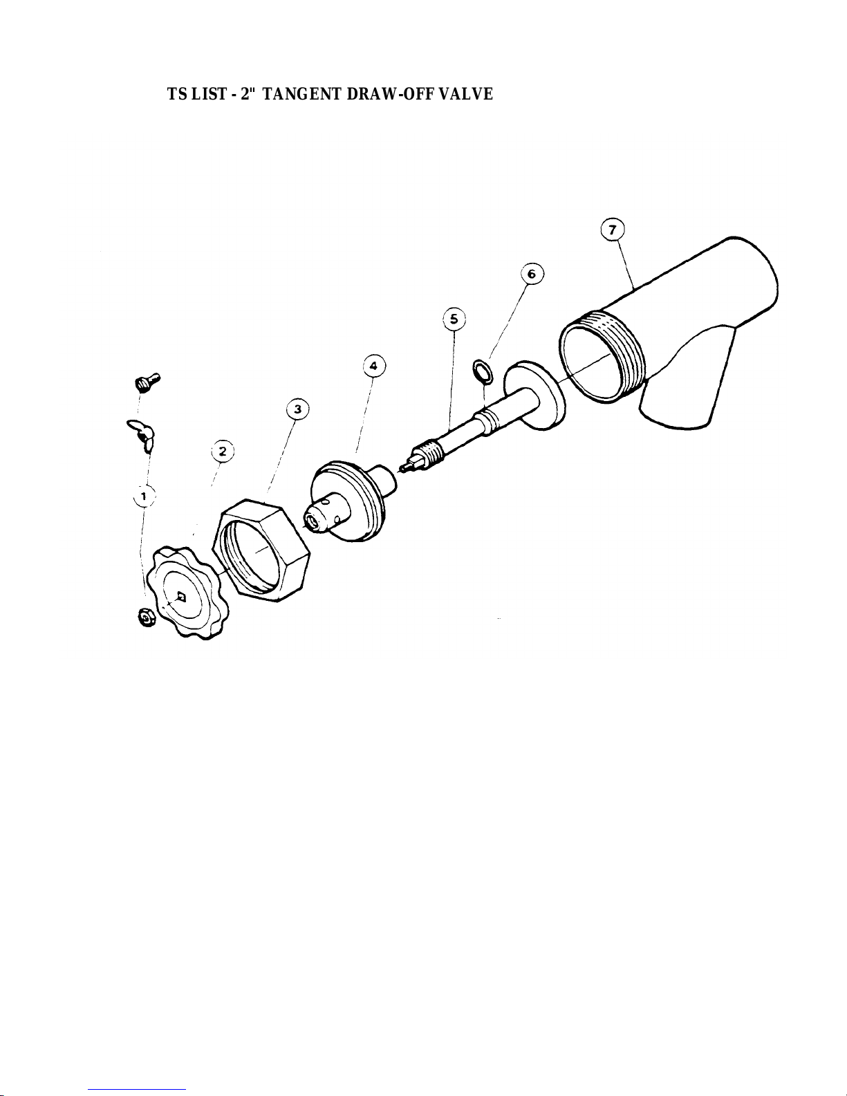
PARTS LIST - 2" TANGENT DRAW-OFF VALVE
ITEM NO. PART NO. DESCRIPTION QTY.
1. to 7. KE50972-B Draw-off assembly 1
1. FA21008 Hex nut 1
2.
3. KE52754 Hex nut 1
4. KE52753 Retainer 1
5. KE52752 Piston 1
6. FA00111 "O" Ring 1
7. KE52751 Valve body 1
FA95049 Wing nut
KE527551 Knob 1
16
Page 19
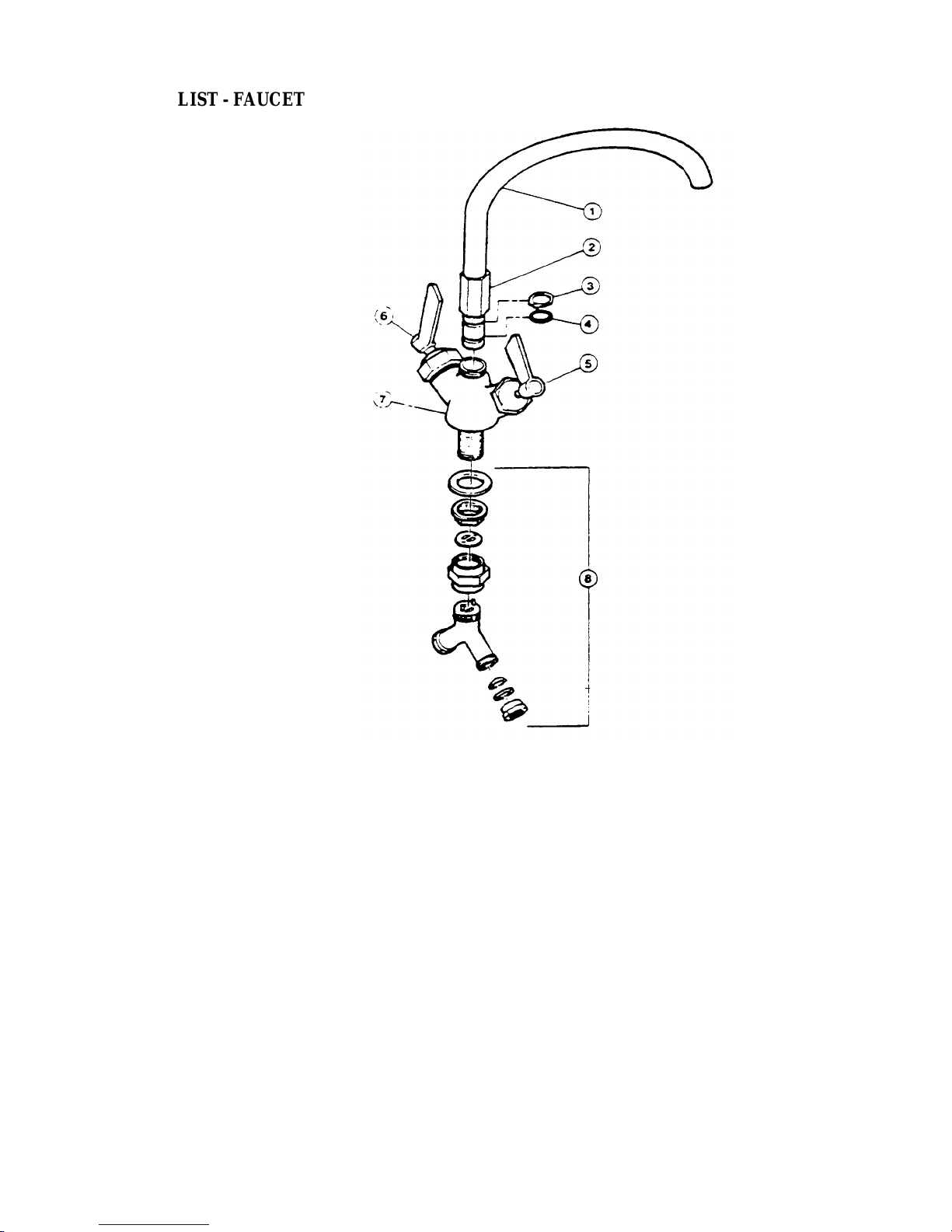
PARTS LIST - FAUCET
ITEM NO. PART NO. DESCRIPTION QTY.
1
2 KE51404 Spout nut, short(used on spout KE50833) 1
KE50833 for KS-E-LA
KE50828 for KT-20-EA
KE50829 for KT-30-EA, KT-4O-EA, KT-60-EA
KE51736 Spout nut, tall (used on spouts 1
3 FA95022 Retaining ring 1
4 FA00016 "O"ring 1
5 SE50021 Cold water stem assemby 1
6 SE50020 Hot water stem assembly 1
7 KE51403 Double pantry control valve
8 SE50022 Yoke connection kit 1
3/4" Spout 1
KE50828, KE50829 and KE50830)
(c/w item no. 5,6,8) 1
17
Page 20
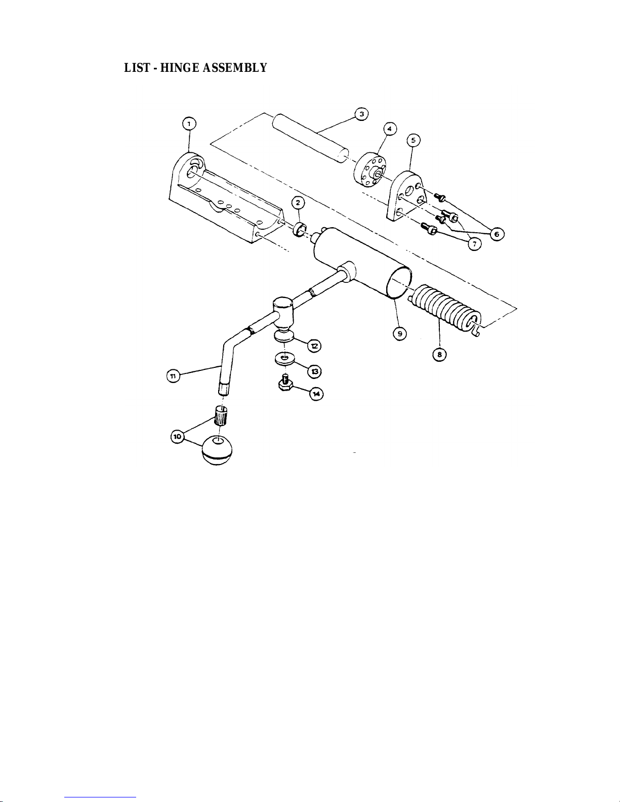
PARTS LIST - HINGE ASSEMBLY
ITEM NO. PART NO. DESCRIPTION QTY.
1.-9. SE00057 Hinge assembly (40 gal. and under) 1
1. KE51218 Body, spring assist hinge 1
2. KE50824 Hinge bearing 1
3. KE50823 Pin (hinge) 1
4. KE50820 Insert, brass adjustment 1
5. KE50819 End piece 1
6. FA11507 Screws, adjustment 2
7. FA11284 Bolts, end block 2
8. KE50122 Spring (40 gal. and under) 1
9. KE50821 Cylinder 1
10. KE50151 Knob, ball type 1
11.
12. KE00095 Lid holder 1
13. FA30500 Washer, lid holder 1
14. FA11223 Bolt, lid holder 1
SE00058 Hinge assembly (60 gal. and over) 1
KE50121 Spring (60 gal. and over) 1
Cover handle (specify model) 1
18
Page 21
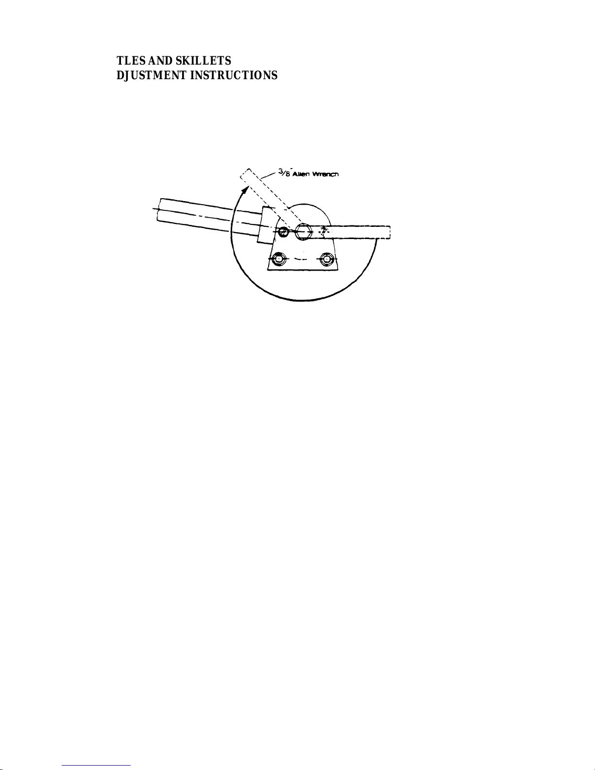
ALL KETTLES AND SKILLETS
HINGE ADJUSTMENT INSTRUCTIONS
1. Insert 3/8" Allen wrench.
2. Turn clockwise to relieve tension on spring.
3. While tension is released remove one of the two slotted screws.
4. To prevent Allen wrench from springing back abruptly while the second slotted screw is
removed, insert a pin (approximately 1/8") in the hole where the first slotted screw was
removed from.
5. Remove second slotted screw.
6. While holding Allen wrench remove pin.
7. Turn Allen wrench clockwise to tighten or counter-clockwise to loosen tension to produce
desired effect.
8. Re-insert pin in one of the two holes.
9. Tighten one slotted screw in the other hole (it may be necessary to turn Allen wrench
slightly to align holes.)
10. Remove pin and repeat step number 9 for other slotted screw.
19
Page 22
ALL ELECTRIC KETTLES
SERVICING GUIDE
This section contains servicing information intended for use by Authorized Service Personnel.
Note 1: If Fault Isolation Procedure is required, be sure to start at step #1.
Note 2: On table top kettles the entire control mounting panel may be removed from kettle control
housing for easier troubleshooting and pans replacement.
A/ Problem: Kettle is not heating at all. (Kettle must be on and temperature control set.)
Possible Causes
1. No incoming power. 8. Defective potentiometer.
2. Kettle is tilted. 9. Defective low water level probe.
3. Low water condition. 10. Defective thermistor.
4. Defective on/off switch. 11. Defective 240/16 VAC transformer.
5. Defective 12 VDC relay. 12. Defective control box.
6. Defective safety thermostat. 13. Defective elements.
7. Defective contactor/s.
Fault Isolation Procedure
Step Test Result Remedy
1. Is there proper incoming voltage at terminal
block?
2. Is the red LED illuminated? Yes Follow Kettle Filling Procedure. If this does
3. Is the green LED illuminated? Yes Go to step #4.
4. Do both contactors energize? Yes Check contactor contacts for pitting. Voltage
Yes Go to step #2.
No Correct external power supply problem.
not correct the problem, go to PROBLEM D.
No Go to step #3 .
No Go to step #7
across contactor terminals while in a closed
position indicates a poor contact. Replace
contactor/s as necessary. Check elements for
short at ground or an open circuit. If element/s
are defective contact the factory. Elements are
not field replaceable.
No Go to step #5.
20
Page 23
5. Measure continuity across safety thermostat.
Is it an open circuit?
6. Is there 120 VAC present across the coils of
the contactors?
Yes Replace defective safety thermostat.
No Go to step #6.
Yes Replace defective contactor/s.
No Replace defective 12 VDC relay.
7. Remove wire from low water level probe
and ground it to the body of the kettle. Do
the contactors now energize?
8. Is there 16 VAC present at output of 16
VAC transformer?
9. Measure continuity of ON/OFF switch. Is it
operating properly?
10. Unplug control box and measure the
resistance across potentiometer. Is it approx.
0 ohms at max. and 50,000 ohms at min.
settings?
Yes Clean or replace defective low water level
probe. Replace defective red LED.
No Go to step #8.
Yes Go to step #9.
No Replace defective 240/16 VAC transformer.
Yes Go to step #10.
No Replace defective ON/OFF switch.
Yes Go to step #11.
11. Remove edge connector from control box.
While kettle is cold or thermistor is removed
and allowed to cook, measure the resistance
between edge connectors pins #2 and #7. Is
it approx. 100,000 ohms?
No Replace defective potentiometer.
Yes Spray contact cleaner on control box
terminals and edge connector. Try box
again, if the problem still exists, replace
defective control box.
No Replace defective thermistor.
21
Page 24
B/ Problem: Kettle heats too slowly or not hot enough.
signifies a poor contact. Replace contactor/s as
.
(Note: normal max. operating pressure with an empty kettle is 25-30 psi.)
Possible Causes
1. Air in kettle jacket-requires venting. 5. Defective contactors.
2. Defective safety thermostat. 6. Defective control box.
3. Defective potentiometer. 7. Defective element/s.
4. Defective thermistor.
Fault Isolation Procedure
Step Test Result Remedy
1. In a cold state, does the pressure gauge read in
the green zone?
2. Yes Go to step #3.
Do the contactors shut off too early? (before
reaching normal max. operating pressure).
3. Yes Replace defective safety thermostat.
Does the green LED remain illuminated after the
contactors shut off?
Yes Go to step #2.
No There is air present in the jacket of the kettle.
Follow Kettle Venting Procedure. If constant
venting is required, there is a leak that should
be corrected.
No Check contactor contacts for pitting. Voltage
across terminal of contactor while energized
necessary. Check elements for short to ground
or open circuit If elements are defective,
contact the factory. Elements are not field
replaceable.
4. Yes Go to step #5 .
Unplug control box and measure the resistance
across potentiometer.
Is it approx. 0 ohms at max. and 50,000 ohms at
min. setting? No Replace defective potentiometer.
5. Yes Go to step #6 .
Remove kettle thermistor and allow to cool.
Remove edge connector from control box. Test
resistance across edge connectors pins #2 and #1
Is it approx. 100,000 ohms?
No Go to step #4.
No Replace defective thermistor.
22
Page 25
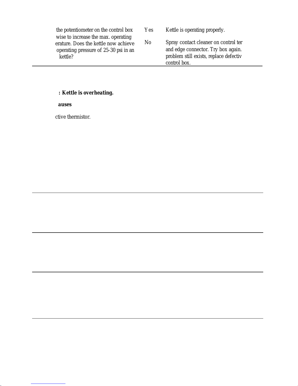
6. Yes Kettle is operating properly.
control box.
Does the green LED turn off even though the
Turn the potentiometer on the control box
clockwise to increase the max. operating
temperature. Does the kettle now achieve
max. operating pressure of 25-30 psi in an
empty kettle?
No Spray contact cleaner on control terminals
and edge connector. Try box again. If
problem still exists, replace defective
C/Problem: Kettle is overheating.
Possible Causes
1. Defective thermistor.
2. Defective potentiometer.
3. Defective 12 VDC relay.
4. Defective control box.
Fault Isolation Procedure
Step Test Result Remedy
1. Yes Replace defective 12 VDC relay.
contractors remain energized?
2. Yes Go to step #3.
Unplug the control box and measure the
No Go to step #2.
resistance across the potentiometer, Is the
resistance approx. 0 ohms at max. and
50,000 ohms at min. settings?
3. Yes Go to step #4.
Remove kettle thermistor an allow to cool.
No Replace defective thermistor.
Remove edge connector from control box.
Test resistance across edge connectors pins
#2 and #7. Is it approx. 100,000 ohms?.
4. Yes Spray contact cleaner on control box
Turn the potentiometer on the control box
counter-clockwise to decrease the max.
operating temperature. Does the kettle
continue to overheat?
No Replace defective thermistor.
terminal and edge connector. Try box
again. If problem still exists, replace
defective control box.
No Kettle is operating properly.
23
Page 26
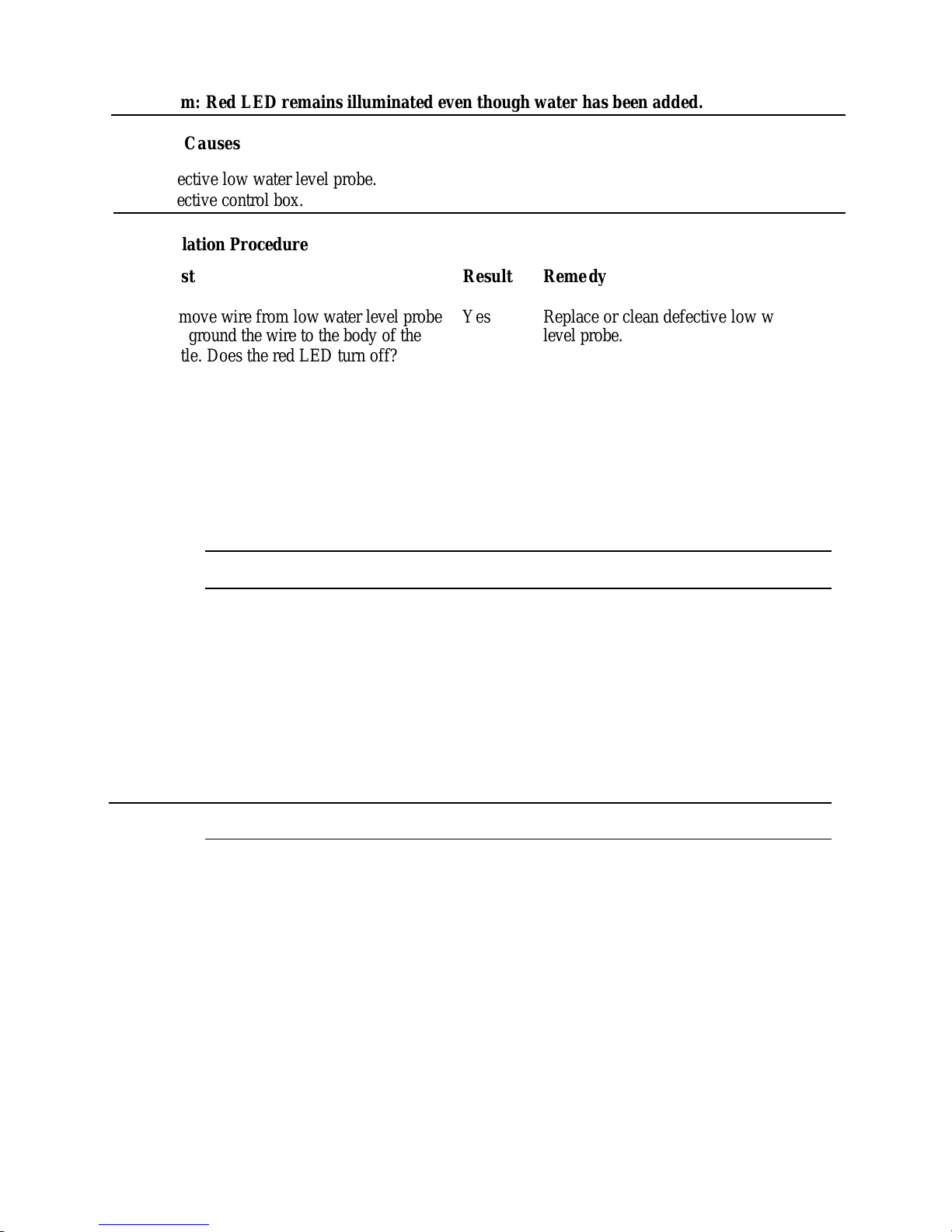
D/Problem: Red LED remains illuminated even though water has been added.
VOLTS
VOLTS
Possible Causes
1. Defective low water level probe.
2. Defective control box.
Fault Isolation Procedure
Step Test Result Remedy
1. Yes Replace or clean defective low water
Remove wire from low water level probe
and ground the wire to the body of the
level probe.
kettle. Does the red LED turn off?
No Spray contact cleaner on control box
terminals and edge connector. Try box
again. If problem still exist, replace
defective control box.
MODEL ELECTRICAL RATINGS
KS20/KT20
KS30/KT30 12.3 59 12.3 34 16.4 68 16.4 39 — — 13.6 21
KS40/KT40 14.8 71 14.8 41 19.6 82 19.6 47 — — 16.4 25
208
1 Phase
KW AMP
9.8 47
3 Phase
KW AMP KW AMP KW AMP KW AMP KW AMP
9.8 27 13 55 13 32 — — 11 25
240 VOLTS
1 Phase
3 Phase
220/380 VOLTS
1 Phase 3 Phase
KS60/KT60 14.8 71 14.8 41 19.6 82 19.6 47 — — 16.4 25
240/416 VOLTS
1 Phase 3 Phase
KS20/KT20
KS30/KT30 — — 16.4 23 9.8 21 9.8 12 18 31 18 18
KS40/KT40 — — 19.6 27 B.I 27 13.1 16 18 31 18 18
KS60/KT60 — — 19.6 27 19.6 41 19.6 24 24 42 24 24
KW AMP
— —
KW AMP KW AMP KW AMP KW AMP KW AMP
13 18 9.8 21 9.8 12 18 31 18 18
1 Phase
480 VOLTS
3 Phase
1 Phase
575
3 Phase
For electrical supply other than shown above, refer to the wiring diagram affixed to the underside of the
console cover.
NOTE: Amperage (amps/ph) column above is the actual current draw of the unit. Please reference
electrical codes in your area for the correct wire and circuit breaker sizing.
24
Page 27
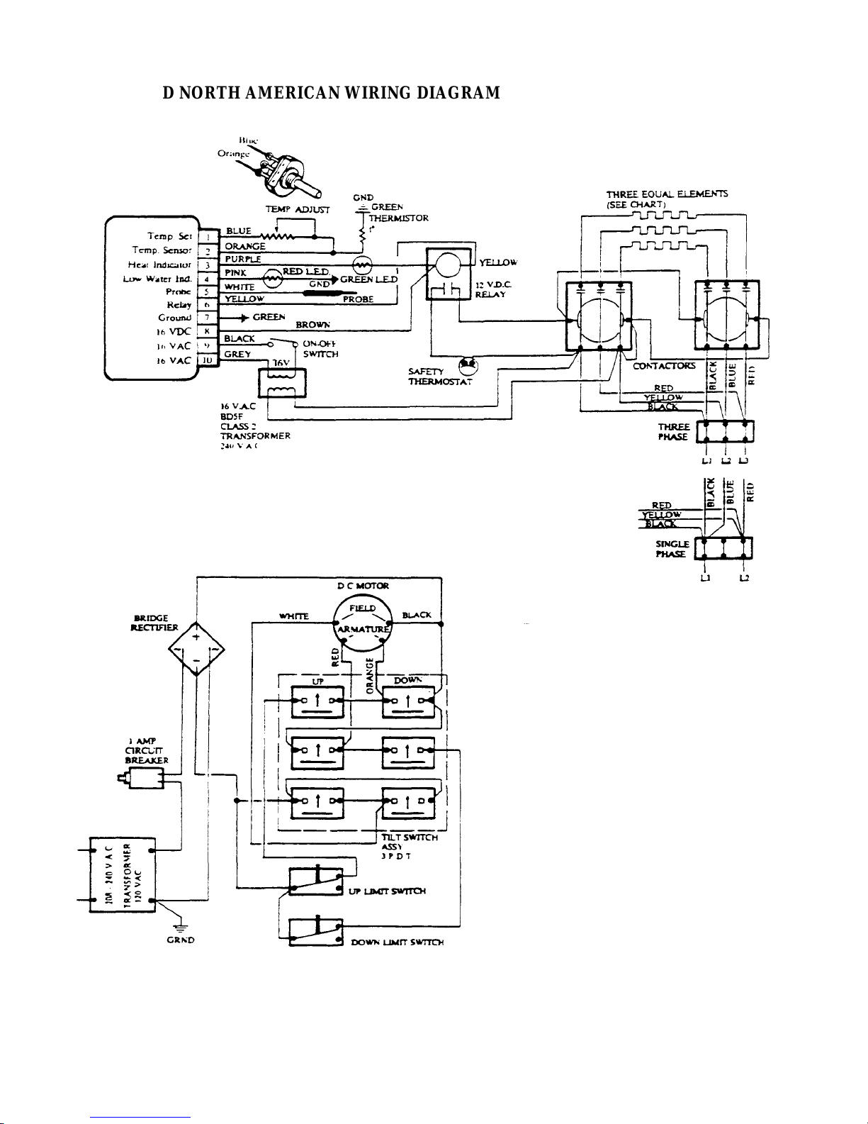
STANDARD NORTH AMERICAN WIRING DIAGRAM
For electrical supply other than shown above, refer to the wiring diagram affixed to the underside of the
console cover.
NOTE: Please reference electrical codes in your area for the correct wire and circuit breaker sizing.
25
Page 28
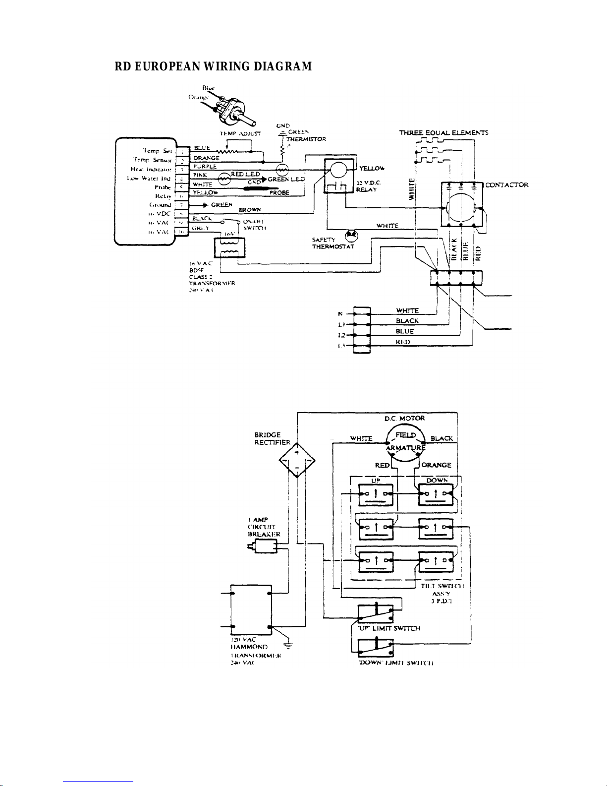
STANDARD EUROPEAN WIRING DIAGRAM
For electrical supply other than shown above, refer to the wiring diagram affixed to the underside of the
console cover.
NOTE: Please reference electrical codes in your area for the correct wire and circuit breaker sizin g.
26
Page 29
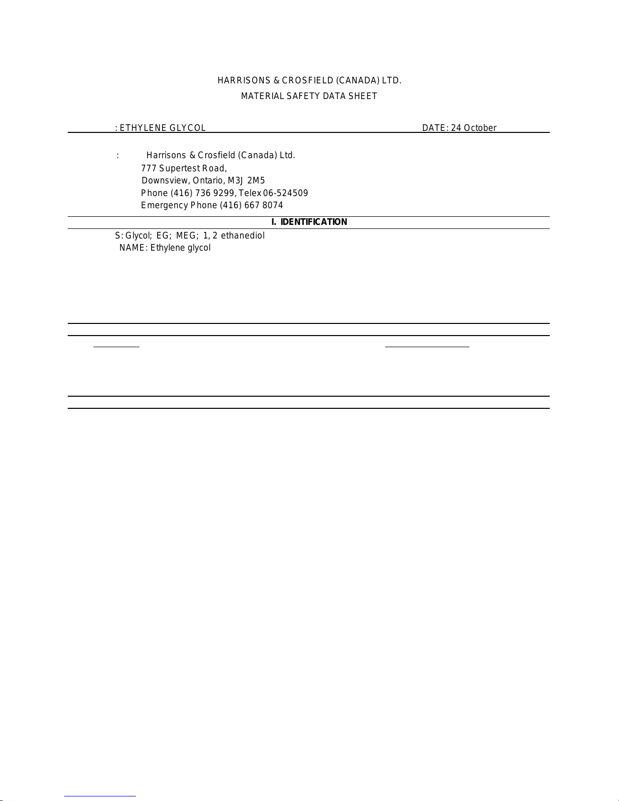
HARRISONS & CROSFIELD (CANADA) LTD.
PRODUCT: ETHYLENE GLYCOL DATE:
24
October
1986
alaise, lumbar pain, oliguria, uraemia,
related teratogenic effects in rats and
suggest that it has caused birth defects in humans. Two chronic feeding studies, using rats and mice have not
related increases in tumour incidence, or a different
glycol has been supported by numerous in vitro genotoxicity studies showing it does not produce mutagenic or
MATERIAL SAFETY DATA SHEET
SUPPLIER: Harrisons & Crosfield (Canada) Ltd.
777 Supertest Road,
Downsview, Ontario, M3J 2M5
Phone (416) 736 9299, Telex 06-524509
Emergency Phone (416) 667 8074
I. IDENTIFICATION
SYNONYMS: Glycol; EG; MEG; 1, 2 ethanediol
CHEMICAL NAME: Ethylene glycol
CHEMICAL FAMILY: Glycols
CHEMICAL FORMULA: HOC2H4CH C.A.S. NUMBER: 107-21-1
SHIPPING NAME:
CLASSIFICATION: Not regulated P.I.N.: PACKING GROUP:
II. HAZARDOUS INGREDIENTS
Ingredient Range % TLV (ppm)
Ethylene glycol 100 Vapor-50 ppm
III. HEALTH HAZARDS
THRESHOLD LIMIT VALUE: Vapour - 50 ppm. Paniculat e - 10 mg/m3
EFFECTS OF OVEREXPOSURE:
EYES: Liquid, vapours, and particularly mists, may cause discomfort in the eye with transient conjunctivitis.
Serious corneal injury is not anticipated.
SKIN: slightly irritating.
INHALATION: May cause irritation of the throat and headache. High vapour concentrations caused, for
example, by heating the material in an enclosed and poorly ventilated workspace may produce nausea,
headache, and dizziness.
INGESTION: May cause abdominal discomfort and pain (dizziness, m
and central nervous system depression. Severe kidney damage follows the swallowing of large volumes of
ethylene glycol. May be fatal.
CHRONIC HEALTH HAZARDS: Inhalation of mists may produce signs of effects on the central nervous
system, particularly dizziness and nystagmus.
OTHER HEALTH HAZARDS: Ethylene glycol has been shown to produce dose -
mice when given by gavage or drinking water at high concentrations. There is no available information to
produced any evidence that ethylene glycols causes dose pattern of tumours compared with untreated controls. The absence of a carcinogenic potential for ethylene
clastogenic effects.
Page 30
PRODUCT: ETEYLENE GLYCOL DATE:
24
October
1986
FIRST AID:
FLAMMABLE LIMITS
(%
in air): LOWER:
3.2
UPPER:
15.3
(est)
BOILING POINT (C)
: 197
SPECIFIC GRAVITY (20C)
: 1.12
VAPOUR PRESSURE:
0.08
VAPOUR DENSITY (air=l)
: 2.1
WATER
SOLUBILITY: Complete VOLATILITY
(%):
Nil EVAPORATION RATE:(Butyl acetate=1):
< 0.01
CONDITIONS TO AVOID: None currently known.
HAZARDOUS DECOMPOSITION PRODUCTS: Carbon dioxide and/or carbon
monoxide produced on burning
.
HAZARDOUS POLYMERIZATION: No.
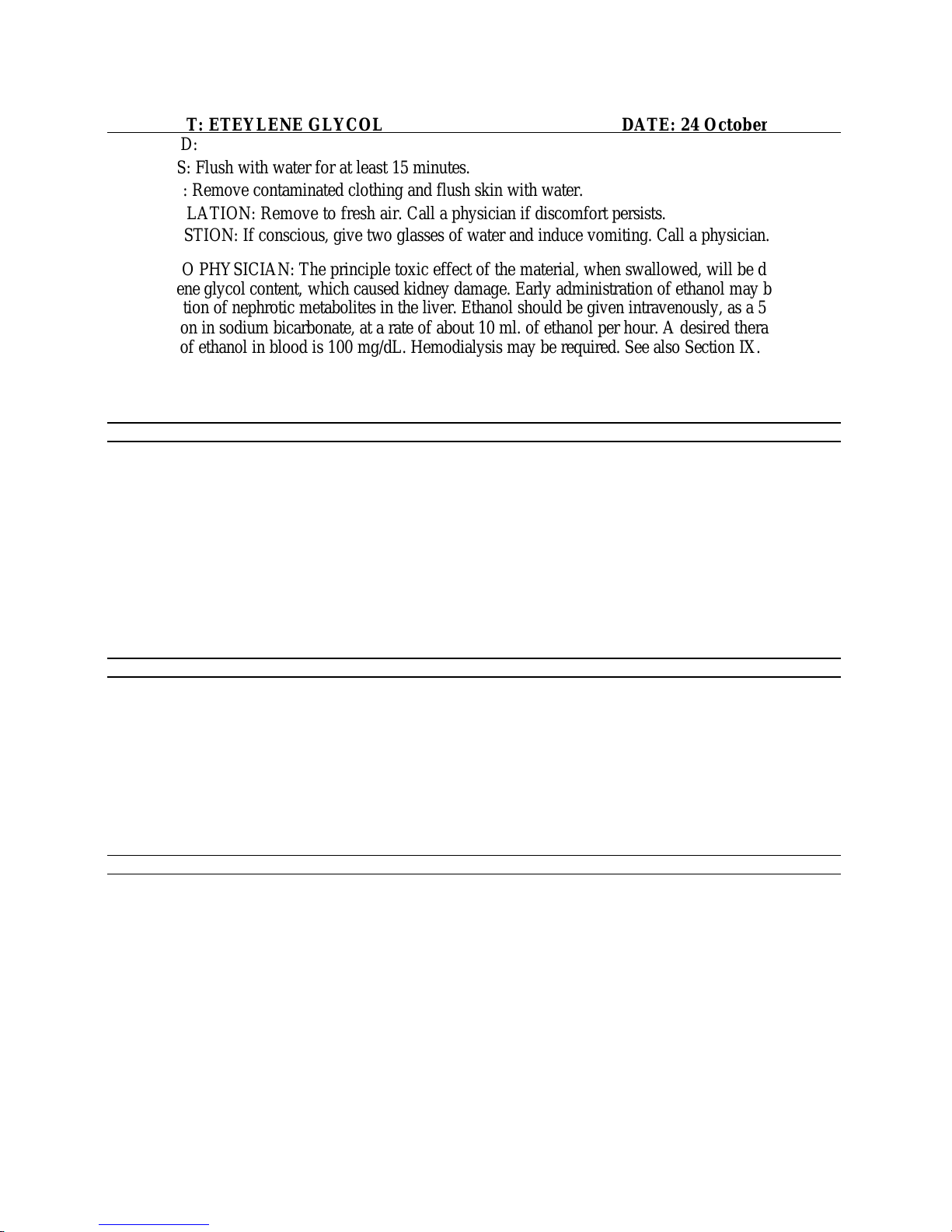
EYES: Flush with water for at least 15 minutes.
SKIN: Remove contaminated clothing and flush skin with water.
INHALATION: Remove to fresh air. Call a physician if discomfort persists.
INGESTION: If conscious, give two glasses of water and induce vomiting. Call a physician.
NOTES TO PHYSICIAN: The principle toxic effect of the material, when swallowed, will be due to the
ethylene glycol content, which caused kidney damage. Early administration of ethanol may block the
formation of nephrotic metabolites in the liver. Ethanol should be given intravenously, as a 5%
solution in sodium bicarbonate, at a rate of about 10 ml. of ethanol per hour. A desir ed therapeutic
level of ethanol in blood is 100 mg/dL. Hemodialysis may be required. See also Section IX.
FLASH POINT & method (C): 116 (TCC)
EXTINGUISHING MEDIA: Use water spray, carbon dioxide, dry chemical, alcohol-type or universal-
type foams applied by the manufacturers' recommended technique.
SPECIAL FIRE FIGHTING PROCEDURES: Do not spray pool fires directly. A solid stream of water
directed into hot, burning liquid can cause frothing. Use self -contained breathing apparatus and
protective clothing.
UNUSUAL FIRE & EXPLOSION HAZARDS: None currently known
The following physical data are approximate only and do not represent specification value s. They
should only be used in the context of this Material Safety Data Sheet.
APPEARANCE & ODOUR: Colourless liquid, mild odour.
STABILITY: Stable.
INCOMPATIBILITY: Strong oxidizing agents.
CONDITIONS TO AVOID: None currently known.
Page 31
PRODUCT: ETEYLENE GLYCOL DATE:
24
October
1986
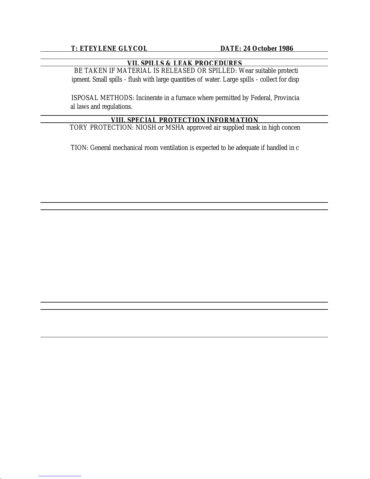
STEPS TO BE TAKEN IF MATERIAL IS RELEASED OR SPILLED: Wear suitable protective
PROTECTIVE
GLOVES: Rubber or plastic.
en described in a number of patients
equipment. Small spills - flush with large quantities of water. Large spills - collect for disposal.
WASTE DISPOSAL METHODS: Incinerate in a furnace where permitted by Federal, Provincial, and
local laws and regulations.
RESPIRATORY PROTECTION: NIOSH or MSHA approved air supplied mask in high concentrations.
VENTILATION: General mechanical room ventilation is expected to be adequate if handled in covered
equipment. Local exhaust ventilation is needed at points where vapour is expected to be vented to
the air.
EYE PROTECTION: Monogoggles or face shield.
ADDITIONAL PROTECTIVE EQUIPMENT: Eye bath and safety shower.
HANDLING & STORAGE: May be fatal if swallowed. Do not breathe mist. Avoid prolonged or repeated
breathing of vapour. Avoid contact with eyes. Wash thoroughly after handling. Where heavy
concentrations of fine mist are present, a respirator should be used to prevent inhaling mist
particles.
OTHER INFORMATION: Pulmonary oedema with hypoxemia has be
following poisoning with ethylene glycol. The mechanism of production has not been elucidated,
but it appears to be noncardiogenic in origin in several cases. Respiratory support with mechanical
ventilation and positive end-expiratory pressure may be required.
PREPARED BY: Regulatory Services DATE ISSUED: 28 July 1986
Harrisons & Crosfield (Canada) Ltd. DATE REVISED:24 Oct. 1986
The information provided in this Material Safety Data Sheet has been obtained from sources believed to be
reliable. Harrisons & Crosfield (Canada) Ltd. provides no warrants express or implied and assumes no
responsibility for the accuracy or the completeness of the da ta contained herein.
Page 32
DEN
SITY (Air=1)
Lower
EMERGENCY Tel. No.
FINNAN ENGINEERED
PRODUCTS LIMITED
MATERIAL SAFETY DATA SHEET
POISON CONTROL CENTER
(416) 438-6070
(416) 294-5237
(416) 497-5512
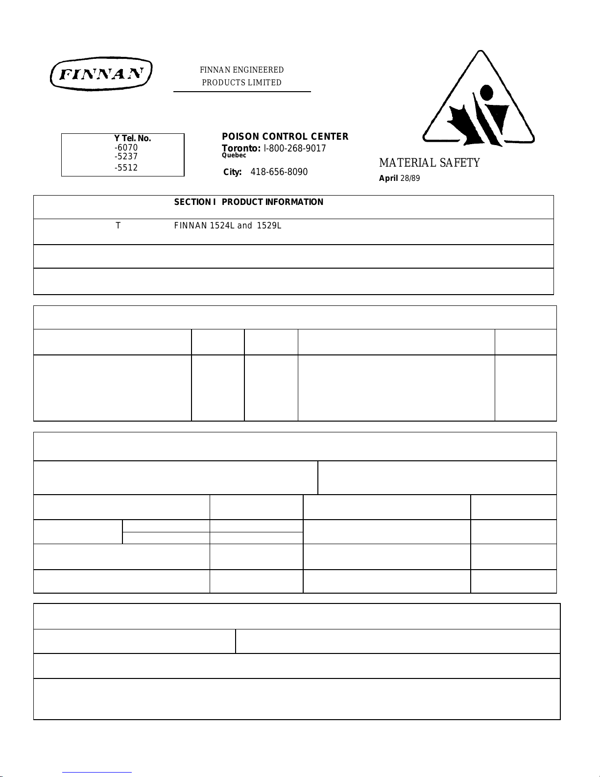
NAME OF PRODUCT FINNAN 1524L and 1529L
PURPOSE OF PRODUCT Closed System Corrosion Inhibitor
CHEMICAL NAME Mixture FORMULA
COMPONENTS WT/ WT
Sodium Nitrite 20-24 120mg/Kg Assists combustion 7632-00-0
Tolytriazole 0.2-0.3 675mg/Kg Toxic 29385-43-1
Sodium Hydroxide 0.8 N/Av. Corrosive 1310-73-2
Sodium Tetraborate 3.3 2660mg/Kg LDL0, man, 709 mg/Kg 1330-43-4
SECTION I PRODUCT INFORMATION
Toronto: l-800-268-9017
Quebec
City : 418-656-8090
SECTION II HAZARDOUS INGREDIENTS
Oral-rat
%
SECTION III PHYSICAL STATE
LD50
April 28/89
HAZARD CAS NO.
APPEARANCE AND PHYSICAL STATE
Straw color liquid
1. BOILING POINT ° C (°F) >100°C 5. pH OF PRODUCT OR ACID/BASE
PRESSURE N/Ave. 2. VAPOUR
3. SOLUBILITY IN WATER Miscible 7. FREEZING POINT N/Av.
4. PERCENT VOLATILE 71% as water 8. AUTODECOMPOSITION TEMP. 490°C
SECTION IV FIRE AND EXPLOSION HAZARD DATA
FLASH POINT N/Ap. FLAMMABLE LIMITS : Upper
EXTINGUISHING MEDIA As appropriate for combustibles in area.
SPECIAL FIRE FIGHTING PROCEDURES
Self -contained breathing apparatus and protective clothing must be worn
in fighting all fires involving chemicals.
ODOUR
Mild
11.5-12.0
CONTENT
6. SPECIFIC GRAVITY (Water=1) 1.20-1. 22
Page 33
materials and dispose of.
Follow your local, provincial and federal chemical disposal regulations.
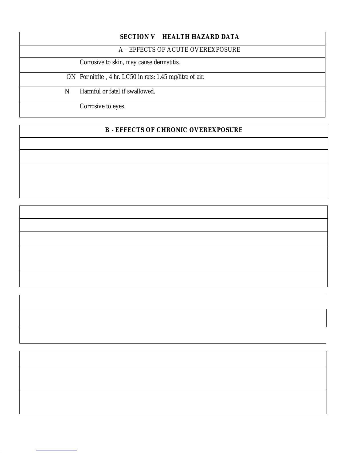
SECTION V HEALTH HAZARD DATA
A - EFFECTS OF ACUTE OVEREXPOSURE
(A) SKIN Corrosive to skin, may cause dermatitis.
(B) INHALATION For nitrite , 4 hr. LC50 in rats: 1.45 mg/litre of air.
(C) INGESTION Harmful or fatal if swallowed.
(D) EYES Corrosive to eyes.
B - EFFECTS OF CHRONIC OVEREXPOSURE
- Nitrite not listed as a carcinogen by ACGIH, IARC or OSH.
- Nitrite tests on animals demonstrate no embryotoxic or reproductive toxicity.
- See Appendix.
SECTION VI EMERGENCY AND FIRST AID
(A) SKIN Wash with soap and water at once while removing contaminated clothing
(B) INHALATION No exposure is expected at room temperature.
(C) INGESTION If victim is conscious, induce vomiting by giving two glasses of water or salt water and inserting
finger down throat. Call Poison Control or a physician immediately.
(D) EYES Immediately flush eyes with copious amounts of water for 20 mins. Consult a physician if
redness or irritation persists.
SECTION VII TOXICOLOGICAL DATA
EXPOSURE LIMITS: Not established.
ROUTE OF ENTRY: Skin or eye contact, ingestion.
SECTION VIII SPILL OR LEAK PROCEDURES
STEPS TO BE TAKEN IN CASE MATERIAL IS RELEASED OR SPILLED
Collect and reuse as much as possible, absorb the residues with sand or other mineral absorbent
DISPOSAL
PROCEDURES
Page 34
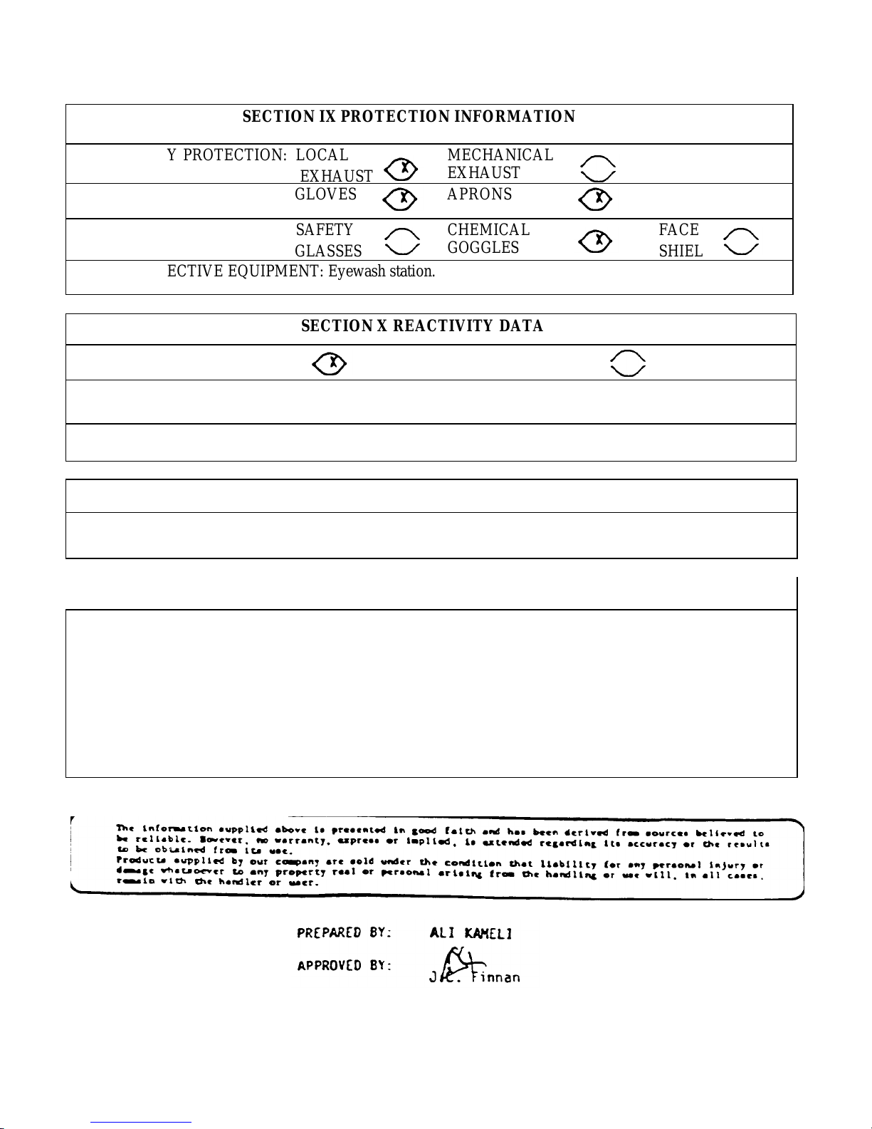
SECTION IX PROTECTION INFORMATION
EXHAUST
EXHAUST
GLASSES
SHIELD
AVOID
RESPIRATORY PROTECTION: LOCAL
MECHANICAL
GLOVES APRONS
SAFETY
CHEMICAL
GOGGLES
OTHER PROTECTIVE EQUIPMENT: Eyewash station.
SECTION X REACTIVITY DATA
STABILITY STABLE UNSTABLE
HAZARDOUS DECOMPOSITION OR COMBUSTION PRODUCTS
Toxic brown nitrogen dioxide gas is formed.
CONDITIONS TO
SECTION XI HANDLING AND STORAGE PRECAUTIONS
Handle as an alkaline liquid. Store away from acids and oxidizing
chemicals. Keep the lid closed at all times.
SECTION XII FURTHER INFORMATION
FACE
Under certain circumstances, when dry nitrite comes in contact with
combustible material, it may act as a source of oxygen, thus
assisting combustion.
Do not add amines to water systems containing Finnan 1524L
or Finnan 1529L to avoid formation of carcinogenic
nitrosamines.
 Loading...