

Operators Manual
Installation, Operation & Service
Floor Model Direct Steam Kettles
MODELS:
KDL, KDL-T, KDL-SH, KDL-TSH,
KDP, KDP-T
™
Clev eland
Enodis
1333 East 179th St., Cleveland, Ohio, U.S.A. 44110
Phone: (216) 481-4900 Fax: (216) 481-3782
Visit our web site at www.clevelandrange.com
SE95007 Rev. 6
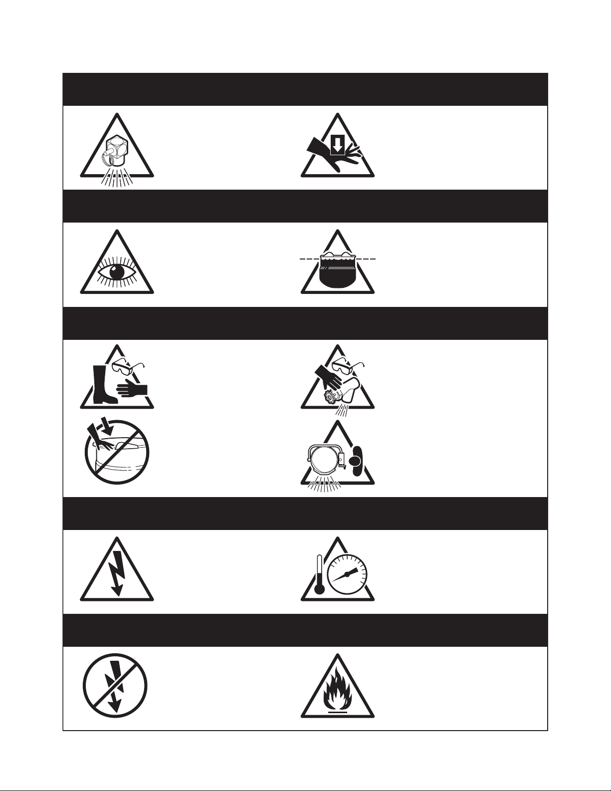
For your safety
DANGER
Keep clear of pressure
relief discharge.
IMPORTANT
Inspect unit daily for
proper operation.
CAUTION
Surfaces may be
extremely hot! Use
protective equipment.
Keep hands away from
moving parts and pinch points.
Do not fill kettle above
recommended level
marked on outside of kettle.
Wear protective equipment
when discharging hot product.
Do not lean on or place
objects on kettle lip.
SERVICING
Shut off power at main
fuse disconnect prior
to servicing.
GAS APPLIANCES
Do not attempt to operate
this appliance during a
power failure.
Stand clear of product
discharge path when
discharging hot product.
Ensure kettle is at room
0
temperature and pressure
gauge is showing zero or less
prior to removing any fittings.
Keep appliance and area free
and clear of combustibles.

GENERAL
Installation of the unit must be accomplished by qualified
installation personnel working to all applicable local and
national codes. Improper installation of product could
cause injury or damage.
This unit is built to comply with applicable standards for
manufacturers. Included among those approval
agencies are: UL, NSF, ASME/Ntl.Bd., CSA, ETL, CE,
and others. Many local codes exist, and it is the
responsibility of the owner/installer to comply with these
codes.
INSPECTION
Before uncrating, visually inspect the unit for evidence
of damage during shipping. If damage is noticed, do
not unpack the unit, follow shipping damage
instructions.
SHIPPING DAMAGE
INSTRUCTIONS
If shipping damage to the unit is discovered or
suspected, observe the following guidelines in
preparing a shipping damage claim.
1. Write down a description of the damage or the
reason for suspecting damage as soon as it is
discovered. This will help in filling out the claim
forms later. If possible, take a polaroid picture.
2. As soon as damage is discovered or suspected,
notify the carrier that delivered the shipment.
3. Arrange for the carrier's representative to examine
the damage.
4. Fill out all carrier claims forms and have the
examining carrier sign and date each form.
INSTALLATION
The first installation step is to refer to the Specification
Sheet for detailed clearance requirements, suggested
drain locations and bolting requirements. Next, carefully
cut open and remove the shipping carton. Remove all
supports and fasteners holding unit to the skid.
KDL SERIES
Position the kettle in its permanent location, and level
the kettle by turning the adjustable flanged feet. Once
positioned and levelled, permanently secure the kettle's
flanged feet to the floor using lag bolts and floor
anchors (to be supplied by the installer).
KDP SERIES
1. Position the kettle in its permanent location, and
mark the floor around the circumference of the
base collar or the base plate. Locate the centre of
this circle and mark the floor at this centre point.
This is the point at which the kettle's base plate will
be secured to the floor.
2. Lay kettle on its side (on a cushioned surface to
prevent scratching), and slide the base collar up
the pedestal, exposing the plate for removal.
3. Remove the four cap screws securing the base
plate and slide it off the kettle.
4. Prepare the floor location, for mounting the kettle,
by installing a 3/4" (19mm) stud, cast into the floor,
at the base plate's centre point. Note: a 3/4"
(19mm) lag bolt and floor anchor may be
substituted for a cast-in stud. The anchor is
installed in the floor, and the lag bolt is threaded
down through the base plate, into the anchor, after
completion of step 6.
5. Thread the four 3/8" (10mm) levelling bolts into
plate from the top, and insert the plate over stud.
6. Adjust bolts until the plate is level.
7. Install a nut on the 3/4" (19mm) bolt (or insert a lag
bolt if the alternate fastener method is used) and
secure base plate to the floor.
8. Check for level "set" of the kettle by placing the
kettle on the base plate with the screw holes
aligned and applying a carpenter's level at the
kettle rim. If the kettle is level, it may be fastened in
place with the four cap screws. If the kettle is not
level, the kettle must be removed from the base,
the plate loosened, and the levelling bolts readjusted until a level installation is attained.
9. Slide the base collar down to the floor, and draw a
line around the circumference of the pedestal at
the top of the collar, using the top of the collar as a
guide. Slide the collar back up the pedestal.
10.
Apply a bead of silicone sealer to the circumference
of the pedestal, at the line, and also to the bottom
rim of the collar. Slide the collar down the pedestal
and press it tightly to the floor. The silicone sealer
will create a seal where the collar meets the
pedestal, and where the collar meets the floor.
SERVICE CONNECTIONS
Install service connections as required. Locations and
other data are shown on the Specification Sheet.
INSTALLATION
STEAM
All steam plumbing to and from the kettle and steam
boiler should be thoroughly cleaned and inspected for
dirt and debris before final connection to the kettle are
made.
Check the rating plate for the maximum steam pressure
that your kettle is rated for. If the steam supply pressure
exceeds the rated pressure, a pressure reducing valve
is required. The steam inlet is at the right side of the
kettle, as seen from the front.
CONDENSATE
A steam condensate trap must be plumbed to a drain,
using minimum 1/2" NPT plumbing. The condensate line is
limited to a maximum rise of 10 feet in order for the steam
pressure to adequately force the condensate through the
plumbing. Any higher rise requires a pump.
If the steam boiler to which this kettle is installed has a
condensate return (closed loop system), a 1/2" steam
strainer, a 1/2" steam trap, and a 1/2" check valve must be
installed on the output (condensate) side of the kettle.
FOR POWER TILT UNITS ONLY
NNOOTTEE
: Ensure the electrical supply matches the kettle's
requirements as stated on the rating label.
This kettle is built to comply with CE standards. Many local
codes exist, and it is the responsibility of the owner and
installer to comply with these codes.
NNOOTTEE
: Maximum voltage for LVD is 440 volts for CE
marked appliances.
POTABLE WATER
The water faucet (optional) with swing spout, requires 1/2
inch O.D. copper tube plumbing for hot or cold water
supplies to the faucet (SPK - cold water connection only,
DPK - hot and cold water connection).
FINAL INSTALLATION CHECK
1. Partially fill the kettle with water.
2. Slowly turn the steam supply valve's knob to the
open position.
3. Release the safety valve, ensuring that the steam
escapes freely. Stay clear of steam exhaust when
releasing the safety valve.
4. Observe that the water in the kettle comes to a
boil.
5. Close the steam supply valve.
6. Drain off the water in the kettle.
CLEANING
After installation the kettle must be thoroughly cleaned
and sanitized prior to cooking. See CLEANING
INSTRUCTIONS for detailed information and suggested
cleaners.
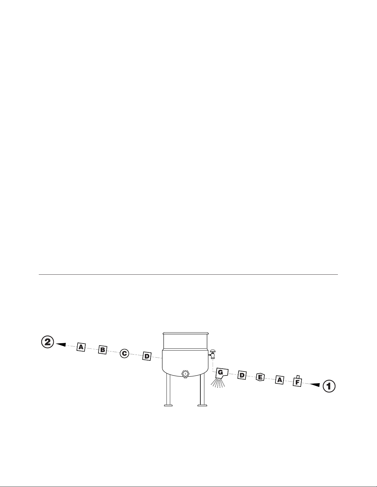
RECOMMENDED PIPING
SCHEMATICS
(all service connections shown supplied by others)
1 Steam In
2 To Drain or Boiler Condensate Line
A Union
B Check Valve
C Steam Trap
D Strainer
E Pressure Reducing Valve
F Shut Off Valve
G Pressure Relief Valve

STEAM REQUIREMENTS FOR KETTLES
Kettle Cap. Kettle 25 psi Steam 265°F 40 psi Steam 287°F 80 psi Steam 302°F
U.S. Gal. Dia. Lbs./Hr. Hp./Hr. Lbs./Hr. Hp./Hr. Lbs./Hr. Hp./Hr.
40 26" 100 3 120 4 150 4.5
60 29.5" 150 4.5 190 5.5 230 7.0
80 33" 210 6.0 260 7.5 300 9.0
100 36" 260 7.5 320 9.5 390 11.0
125 40" 320 9.5 400 11.5 470 14.0
150 40" 390 11.0 480 14.0 570 17.0
Steam requirements are maximum per hour.
If more than one unit is on the same line then add the steam usage for each one to reach a total.
STEAM PIPE SIZING
Required pipe length in feet/meters
Steam Required 200 Ft. 400 Ft. 600 Ft.
Lbs./Kg. per hour 60 Meters 125 Meters 185 Meters
100/45 Kg. 3/4" 1" 1 1/4"
200/91 Kg. 1" 1 1/4" 1 1/2"
300/136 Kg. 1" 1 1/4" 1 1/2"
400/182 Kg. 1" 1 1/2" 1 3/4"
500/227 Kg. 1 1/4" 1 1/2" 1 3/4"
700/318 Kg. 1 1/2" 1 3/4" 2"
900/409 Kg. 1 1/2" 1 3/4" 2"
NOTES:
Pipe size in inches.
Less than 50 PSI (3.4
BAR) pressure, increase
pipe size by 1/4".
80 to 100 PSI (5.5 to 6.8
BAR), Decrease pipe
size by 1/4".
OPERATING INSTRUCTIONS
CLEVELAND STEAM COOKING EQUIPMENT IS INTENDED FOR
COMMERCIAL USE ONLY BY PROFESSIONALLY TRAINED PERSONNEL.
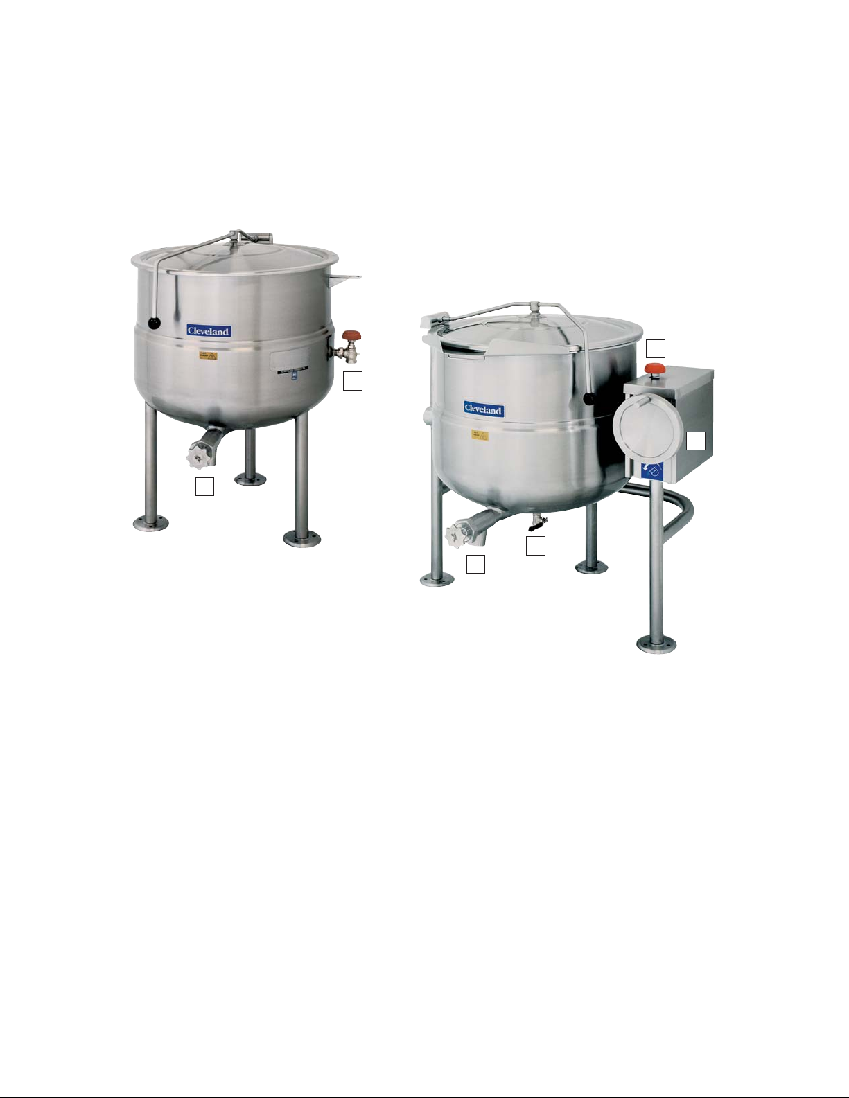
General Parts Drawing
ITEM # DESCRIPTION
1. Steam Inlet Valve Opens and closes the steam supply to the kettle.
2. Hand Wheel Used for tilting the kettle up or down. Some units have an optional
Power Tilt Control Switch located in the same position.
3. Power Tilt Switch Used for tilting the kettle up or down.
(not shown)
4. Drain Cock Used to drain condensate from the bottom of tilting units only.
5. Tangent Draw-Off Valve Used for draining product or wash water from kettle. It is supplied as
standard equipment on stationary kettles and is optional on tilting kettles
.
6. Pressure Relief Valve In the unlikely event that there is an excess steam build-up in the
(not shown) jacket, this valve automatically opens to relieve this pressure.
1
1
2
4
5
5
 Loading...