

Page 1
Cleveland
™
P
roject ________________________________
Item __________________________________
Quantity _______________________________
F
CSI Section ____________________________
A
pproval _______________________________
D
ate __________________________________
1333 East 179 St.,
Cleveland, Ohio, U.S.A. 44110
Tel: 1-216-481-4900
Fax: 1-216-481-3782
Web Site: www.ClevelandRange.com
Email: Steam@ClevelandRange.com
UNIT A
UNIT B
NOTE: Overall height of unit does not change for units with casters.
R
C
C
S
W1 W2
D
G
RC
CS
W1 W2
D
G
4.38"
38.08"
39.21"
L
EFT SIDE VIEW
UNIT A
UNIT B
36.70"
1.58"
28.43
5
.00"
1
.82"
67.8 5 "
28.43
6.00"
78.00” (MIN. HOOD REQUIREMENT)
2.52"
G
D
RC
CS
W1
W2
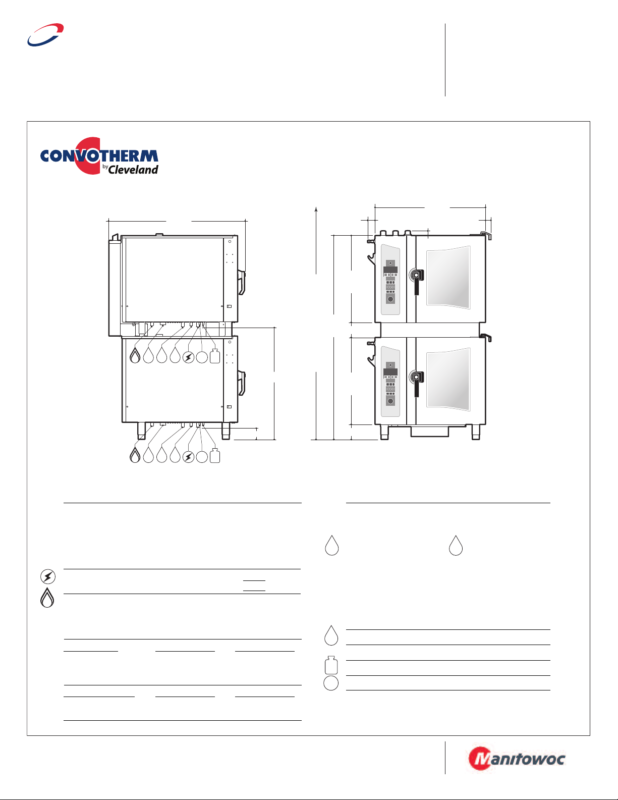
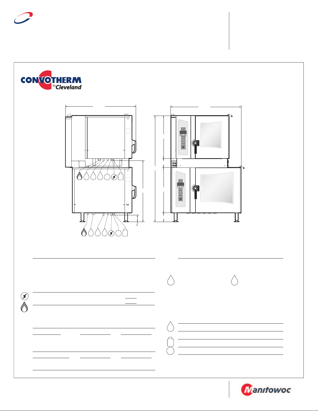
COMBI OVEN-STEAMER
Stacking Kits for Gas Table Type Models
(OGB 6.10 on OGB 6.10 or OGS 6.10 on OGS 6.10)
Model # Description
CSTK610 for mounting two 6.10 models
STK610CA for mounting two 6.10 models (with casters)
C
UTILITIES (Utility connection shown below are listed per unit)
Required Clearances:
• Allow for sufficient distance if a "high heat source" (i.e. Broiler) is located
next to the unit.
• Allow for sufficient clearance on left side for service access (contact the
factory service department for recommendations).
• Installation must comply with all local fire and health codes.
Electrical Requirements:
Do not connect to a G.F.I. outlet.
Gas Connection: 3/4" NPT
Gas Type: Natural Gas (Propane optional)
Gas Flow Pressure: Natural Gas - Min. 5.5" WC / Max. 14" WC
BOILER MODELS
Total Connected Load: 45.400 BTU 45.400 BTU
Steam Generator: 45.400 BTU 45.400 BTU
Hot Air: 45.400 BTU 45.400 BTU
BOILERLESS MODELS
Total Connected Load: 45.400 BTU 45.400 BTU
Hot Air: 45.400 BTU 45.400 BTU
Rear - 2", Left Side - 4", Right Side - 2 1/2"
120 volt, 60 Hz, single phase,
UNIT A UNIT B -
11.7 amps
11.7 amps
Propane Gas - Min. 11" WC / Max. 14" WC
UNIT A - OGB 6.10 UNIT B - OGB 6.10
UNIT A - OGS 6.10 UNIT B - OGS 6.10
Water Connections: Cold Water (drinking water quality)
Flow Pressure: 35 - 60 PSI
Water Inlets:
Treated Water for Steam Generator Untreated Water for Condenser
NOTE: The owner / operator / purchaser must ensure that the Water Quality
Requirements are met. Not meeting the water quality requirements will void the
original equipment warranty.
Water Quality Requirements:
TDS . . . . . . . . . . . . < 60 ppm pH Factor . . . . . 7.0 – 8.5
Total Alkalinity . . . . < 20 ppm Free Chlorine. . . < 0.1 ppm
Silica . . . . . . . . . . . < 13 ppm Conductivity . . . min. 20 µS/cm (50 kOhms)
Chloride . . . . . . . . < 25 ppm
3/4" GHT-F (Female Garden Hose Connection)
Drain Connection: 2" Tube
Venting: Exhaust Hood required
Connection for Cleaning Solution (Available as an option)
Connection for Rinse Cycle (Available as an option)
Note: For additional connection details, see spec sheet
for each individual combi model to be stacked.
SECT. IIB PAGE 5A
0810
Page 2
Cleveland
™
P
roject ________________________________
Item __________________________________
Quantity _______________________________
F
CSI Section ____________________________
A
pproval _______________________________
D
ate __________________________________
1333 East 179 St.,
Cleveland, Ohio, U.S.A. 44110
Tel: 1-216-481-4900
Fax: 1-216-481-3782
Web Site: www.ClevelandRange.com
Email: Steam@ClevelandRange.com
UNIT A
UNIT B
RC
CS
W1 W2
D
G
RC
C
S
W1 W2
D
G
4.38"
48.54”
39.21"
NOTE: Overall height of unit does not change for units with casters.
U
NIT A
UNIT B
L
EFT SIDE VIEW
78.41"
36.70"
1.58"
1.82"
28.43
5.00"
38.98"
6.00"
80.00” (MIN. HOOD REQUIREMENT)
2.52"
G
D
RC
CS
W1
W2
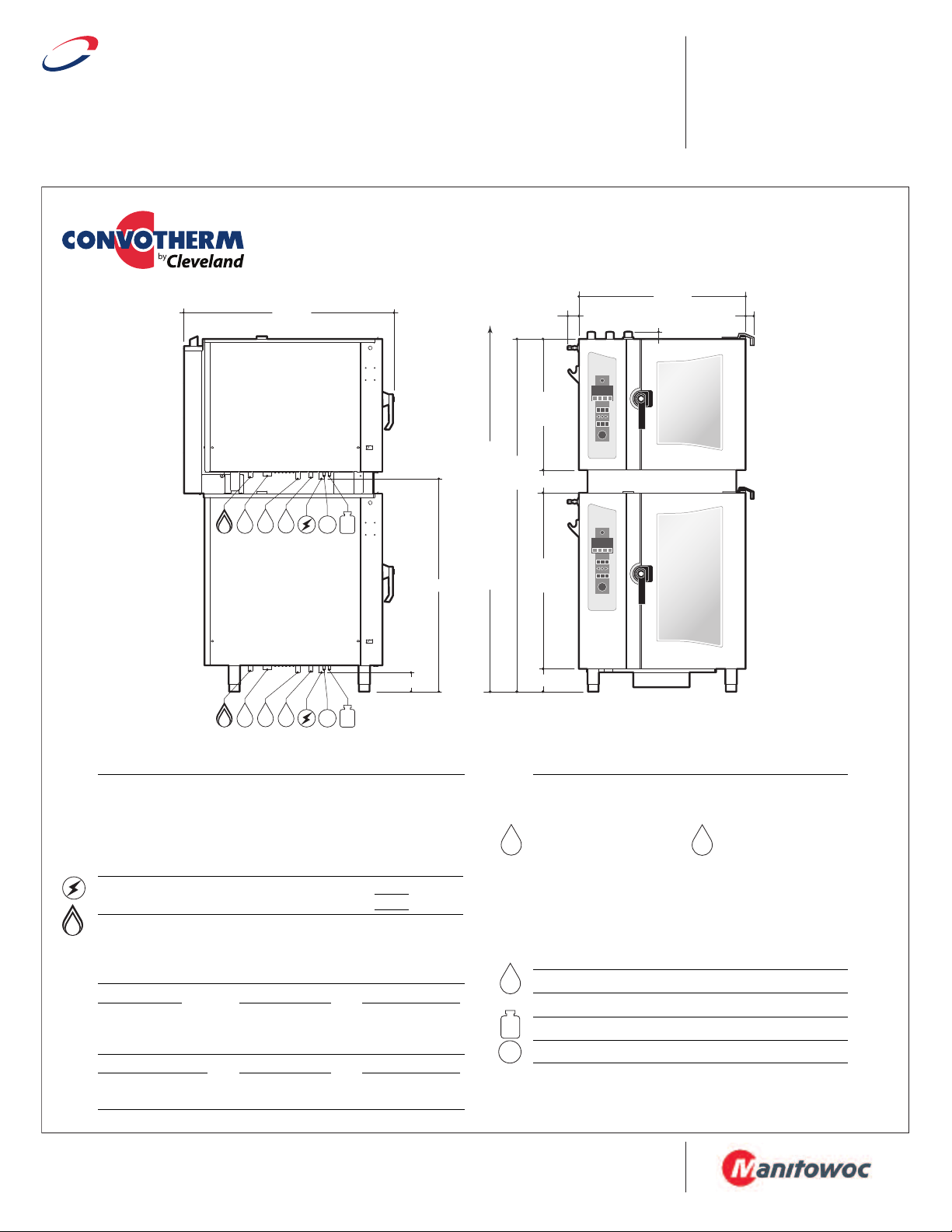
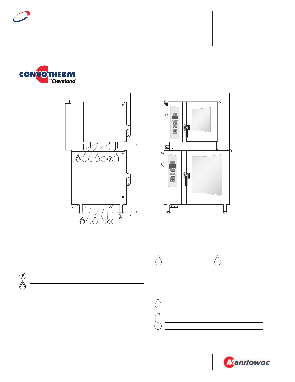
COMBI OVEN-STEAMER
Stacking Kits for Gas Table Type Models
(OGB 6.10 on OGB 10.10 or OGS 6.10 on OGS 10.10)
Model # Description
CSTK1010 for mounting one 6.10 model on top of one 10.10 model
CSTK1010CA for mounting one 6.10 model on top of one 10.10 model (with casters)
UTILITIES (Utility connection shown below are listed per unit)
Required Clearances:
• Allow for sufficient distance if a "high heat source" (i.e. Broiler) is located
next to the unit.
• Allow for sufficient clearance on left side for service access (contact the
factory service department for recommendations).
• Installation must comply with all local fire and health codes.
Electrical Requirements:
Do not connect to a G.F.I. outlet.
Gas Connection: 3/4" NPT
Gas Type: Natural Gas (Propane optional)
Gas Flow Pressure: Natural Gas - Min. 5.5" WC / Max. 14" WC
BOILER MODELS
Total Connected Load: 45.400 BTU 75,700 BTU
Steam Generator: 45.400 BTU 68,200 BTU
Hot Air: 45.400 BTU 75,700 BTU
BOILERLESS MODELS
Total Connected Load: 45.400 BTU 75,700 BTU
Hot Air: 45.400 BTU 75,700 BTU
Rear - 2", Left Side - 4", Right Side - 2 1/2"
120 volt, 60 Hz, single phase,
UNIT A UNIT B -
11.7 amps
11.7 amps
Propane Gas - Min. 11" WC / Max. 14" WC
UNIT A - OGB 6.10 UNIT B - OGB 10.10
UNIT A - OGS 6.10 UNIT B - OGS 10.10
3/4" GHT-F (Female Garden Hose Connection)
Water Connections: Cold Water (drinking water quality)
Flow Pressure: 35 - 60 PSI
Water Inlets:
Treated Water for Steam Generator Untreated Water for Condenser
NOTE: The owner / operator / purchaser must ensure that the Water Quality
Requirements are met. Not meeting the water quality requirements will void the
original equipment warranty.
Water Quality Requirements:
TDS . . . . . . . . . . . . < 60 ppm pH Factor . . . . . 7.0 – 8.5
Total Alkalinity . . . . < 20 ppm Free Chlorine. . . < 0.1 ppm
Silica . . . . . . . . . . . < 13 ppm Conductivity . . . min. 20 µS/cm (50 kOhms)
Chloride . . . . . . . . < 25 ppm
Drain Connection: 2" Tube
Venting: Exhaust Hood required
Connection for Cleaning Solution (Available as an option)
Connection for Rinse Cycle (Available as an option)
SECT. IIB PAGE 5B
0810
Note: For additional connection details, see spec sheet
for each individual combi model to be stacked.
Page 3
Cleveland
™
P
roject ________________________________
Item __________________________________
Quantity _______________________________
F
CSI Section ____________________________
A
pproval _______________________________
D
ate __________________________________
1333 East 179 St.,
Cleveland, Ohio, U.S.A. 44110
Tel: 1-216-481-4900
Fax: 1-216-481-3782
Web Site: www.ClevelandRange.com
Email: Steam@ClevelandRange.com
2.52"
30.12"
5.00"
30.12"
6.00"
47.92"
1.58"
1.82"
71.24"
NOTE: Overall height of unit does not change for units with casters.
78.00” (MIN. HOOD REQUIREMENT)
RC
CS
W1 W2
D
G
RC
CS
W1 W2
D
G
4.38"
39.50"
47.72"
U
NIT A UNIT A
UNIT B
UNIT B
LEFT SIDE VIEW
FRONT VIEW
G
D
RC
CS
W1
W2
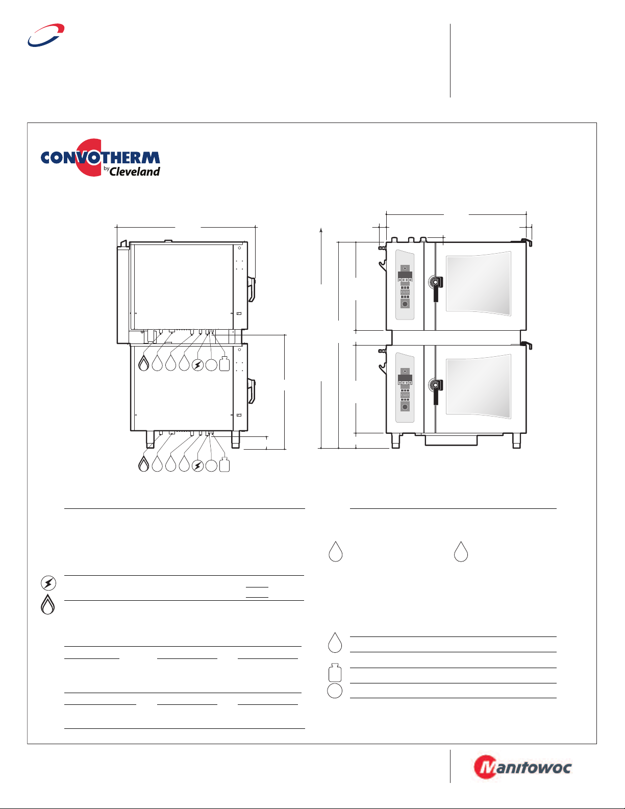
COMBI OVEN-STEAMER
Stacking Kits for Gas Table Type Models
(OGB 6.20 on OGB 6.20 or OGS 6.20 on OGS 6.20)
Model # Description
CSTK620 for mounting two 6.20 models
STK620CA for mounting two 6.20 models (with casters)
C
UTILITIES (Utility connection shown below are listed per unit)
Required Clearances:
• Allow for sufficient distance if a "high heat source" (i.e. Broiler) is located
next to the unit.
• Allow for sufficient clearance on left side for service access (contact the
factory service department for recommendations).
• Installation must comply with all local fire and health codes.
Electrical Requirements:
Do not connect to a G.F.I. outlet.
Gas Connection: 3/4" NPT
Gas Type: Natural Gas (Propane optional)
Gas Flow Pressure: Natural Gas - Min. 5.5" WC / Max. 14" WC
BOILER MODELS
Total Connected Load: 75,700 BTU 75,700 BTU
Steam Generator: 68,200 BTU 68,200 BTU
Hot Air: 75,700 BTU 75,700 BTU
BOILERLESS MODELS
Total Connected Load: 75,700 BTU 75,700 BTU
Hot Air: 75,700 BTU 75,700 BTU
Rear - 2", Left Side - 4", Right Side - 2 1/2"
120 volt, 60 Hz, single phase,
Propane Gas - Min. 11" WC / Max. 14" WC
UNIT A - OGB 6.20 UNIT B - OGB 6.20
UNIT A - OGS 6.20 UNIT B - OGS 6.20
UNIT A -
11.7 amps
UNIT B -
11.7 amps
Water Connections: Cold Water (drinking water quality)
Flow Pressure: 35 - 60 PSI
Water Inlets:
Treated Water for Steam Generator Untreated Water for Condenser
NOTE: The owner / operator / purchaser must ensure that the Water Quality
Requirements are met. Not meeting the water quality requirements will void the
original equipment warranty.
Water Quality Requirements:
TDS . . . . . . . . . . . . < 60 ppm pH Factor . . . . . 7.0 – 8.5
Total Alkalinity . . . . < 20 ppm Free Chlorine. . . < 0.1 ppm
Silica . . . . . . . . . . . < 13 ppm Conductivity . . . min. 20 µS/cm (50 kOhms)
Chloride . . . . . . . . < 25 ppm
3/4" GHT-F (Female Garden Hose Connection)
Drain Connection: 2" Tube
Venting: Exhaust Hood required
Connection for Cleaning Solution (Available as an option)
Connection for Rinse Cycle (Available as an option)
Note: For additional connection details, see spec sheet
for each individual combi model to be stacked.
SECT. IIB PAGE 5C
0810
Page 4
Cleveland
™
P
roject ________________________________
Item __________________________________
Quantity _______________________________
F
CSI Section ____________________________
A
pproval _______________________________
D
ate __________________________________
1333 East 179 St.,
Cleveland, Ohio, U.S.A. 44110
Tel: 1-216-481-4900
Fax: 1-216-481-3782
Web Site: www.ClevelandRange.com
Email: Steam@ClevelandRange.com
80.09"
47.92"
2.52"
1.58"
1.82"
30.12"
5.00"
38.98"
6.00"
81.00” (MIN. HOOD REQUIREMENT)
RC
CS
W1 W2
D
G
RC
CS
W1 W2
D
G
4.38"
48.32"
4
7.72"
NOTE: Overall height of unit does not change for units with casters.
UNIT A UNIT A
UNIT B
UNIT B
LEFT SIDE VIEW
FRONT VIEW
G
D
RC
CS
W1
W2
COMBI OVEN-STEAMER
Stacking Kits for Gas Table Type Models
(OGB 6.20 on OGB 10.20 or OGS 6.20 on OGS 10.20)
Model # Description
CSTK1020 for mounting one 6.20 model on top of one 10.20 model
CSTK1020CA for mounting one 6.20 model on top of one 10.20 model (with casters)
UTILITIES (Utility connection shown below are listed per unit)
Required Clearances:
• Allow for sufficient distance if a "high heat source" (i.e. Broiler) is located
next to the unit.
• Allow for sufficient clearance on left side for service access (contact the
factory service department for recommendations).
• Installation must comply with all local fire and health codes.
Electrical Requirements:
Do not connect to a G.F.I. outlet.
Gas Connection: 3/4" NPT
Gas Type: Natural Gas (Propane optional)
Gas Flow Pressure: Natural Gas - Min. 5.5" WC / Max. 14" WC
BOILER MODELS
Total Connected Load: 75,700 BTU 132,700 BTU
Steam Generator: 68,200 BTU 113,600 BTU
Hot Air: 75,700 BTU 132,700 BTU
BOILERLESS MODELS
Total Connected Load: 75,700 BTU 132,700 BTU
Steam Generator: 75,700 BTU 132,700 BTU
Rear - 2", Left Side - 4", Right Side - 2 1/2"
120 volt, 60 Hz, single phase,
Propane Gas - Min. 11" WC / Max. 14" WC
UNIT A UNIT B -
11.7 amps
15.9 amps
UNIT A - OGB 6.20 UNIT B - OGB 10.20
UNIT A - OGS 6.20 UNIT B - OGS 10.20
Water Connections: Cold Water (drinking water quality)
Flow Pressure: 35 - 60 PSI
Water Inlets:
Treated Water for Steam Generator Untreated Water for Condenser
NOTE: The owner / operator / purchaser must ensure that the Water Quality
Requirements are met. Not meeting the water quality requirements will void the
original equipment warranty.
Water Quality Requirements:
TDS . . . . . . . . . . . . < 60 ppm pH Factor . . . . . 7.0 – 8.5
Total Alkalinity . . . . < 20 ppm Free Chlorine. . . < 0.1 ppm
Silica . . . . . . . . . . . < 13 ppm Conductivity . . . min. 20 µS/cm (50 kOhms)
Chloride . . . . . . . . < 25 ppm
Drain Connection: 2" Tube
Venting: Exhaust Hood required
Connection for Cleaning Solution (Available as an option)
Connection for Rinse Cycle (Available as an option)
Note: For additional connection details, see spec sheet
for each individual combi model to be stacked.
3/4" GHT-F (Female Garden Hose Connection)
SECT. IIB PAGE 5D
0810
Page 5
D
RC
CS
W1
W2
Cleveland
™
P
roject ________________________________
Item __________________________________
Quantity _______________________________
F
CSI Section ____________________________
A
pproval _______________________________
D
ate __________________________________
1333 East 179 St.,
Cleveland, Ohio, U.S.A. 44110
Tel: 1-216-481-4900
Fax: 1-216-481-3782
Web Site: www.ClevelandRange.com
Email: Steam@ClevelandRange.com
UNIT A
UNIT B
NOTE: Overall height of unit does not change for units with casters.
6.00"
30.19"
5.98"
28.46"
4.41"
40.73"
70.64"
4
7.82"
47.82"
R
C
C
S
W1 W2
D
RC
CS
W1 W2
D
G
G
G
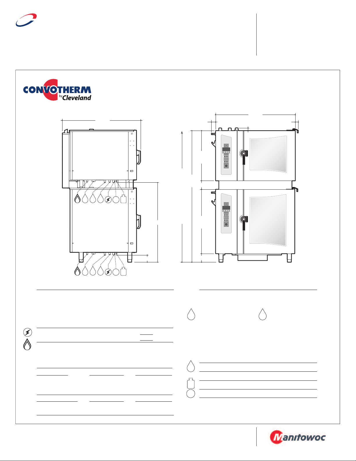
COMBI OVEN-STEAMER
Stacking Kits for Gas Table Type Models
(OGB 6.10 on OGB 6.20 or OGS 6.10 on OGS 6.20)
Model # Description
CSTKG610620 for mounting one 6.10 model on top of one 6.20 model
CSTKG610620CA for mounting one 6.10 model on top of one 6.20 model (with casters)
UTILITIES (Utility connection shown below are listed per unit)
Required Clearances:
• Allow for sufficient distance if a "high heat source" (i.e. Broiler) is located
next to the unit.
• Allow for sufficient clearance on left side for service access (contact the
factory service department for recommendations).
• Installation must comply with all local fire and health codes.
Electrical Requirements:
Do not connect to a G.F.I. outlet.
Gas Connection: 3/4" NPT
Gas Type: Natural Gas (Propane optional)
Gas Flow Pressure: Natural Gas - Min. 5.5" WC / Max. 14" WC
BOILER MODELS
Total Connected Load: 45.400 BTU 75,700 BTU
Steam Generator: 45.400 BTU 68,200 BTU
Hot Air: 45.400 BTU 75,700 BTU
BOILERLESS MODELS
Total Connected Load: 45.400 BTU 75,700 BTU
Hot Air: 45.400 BTU 75,700 BTU
Rear - 2", Left Side - 4", Right Side - 2 1/2"
120 volt, 60 Hz, single phase,
Propane Gas - Min. 11" WC / Max. 14" WC
UNIT A - OGB 6.10 UNIT B - OGB 6.20
UNIT A - OGS 6.10 UNIT B - OGS 6.20
UNIT A -
11.7 amps
UNIT B -
11.7 amps
Water Connections: Cold Water (drinking water quality)
Flow Pressure: 35 - 60 PSI
Water Inlets:
Treated Water for Steam Generator Untreated Water for Condenser
NOTE: The owner / operator / purchaser must ensure that the Water Quality
Requirements are met. Not meeting the water quality requirements will void the
original equipment warranty.
Water Quality Requirements:
TDS . . . . . . . . . . . . < 60 ppm pH Factor . . . . . 7.0 – 8.5
Total Alkalinity . . . . < 20 ppm Free Chlorine. . . < 0.1 ppm
Silica . . . . . . . . . . . < 13 ppm Conductivity . . . min. 20 µS/cm (50 kOhms)
Chloride . . . . . . . . < 25 ppm
3/4" GHT-F (Female Garden Hose Connection)
Drain Connection: 2" Tube
Venting: Exhaust Hood required
Connection for Cleaning Solution (Available as an option)
Connection for Rinse Cycle (Available as an option)
Note: For additional connection details, see spec sheet
for each individual combi model to be stacked.
SECT. IIB PAGE 5E
0810
Page 6
D
RC
CS
W1
W2
Cleveland
™
P
roject ________________________________
Item __________________________________
Quantity _______________________________
F
CSI Section ____________________________
A
pproval _______________________________
D
ate __________________________________
1333 East 179 St.,
Cleveland, Ohio, U.S.A. 44110
Tel: 1-216-481-4900
Fax: 1-216-481-3782
Web Site: www.ClevelandRange.com
Email: Steam@ClevelandRange.com
UNIT A
UNIT B
NOTE: Overall height of unit does not change for units with casters.
6.00"
3
9.04"
5.98"
28.46"
79.49"
4.33"
4
9.57"
4
7.82"
48.11"
R
C
CS
W1 W2
D
RC
CS
W1 W2
D
G
G
G
COMBI OVEN-STEAMER
Stacking Kits for Gas Table Type Models
(OGB 6.10 on OGB 10.20 or OGS 6.10 on OGS 10.20)
Model # Description
CSTKG6101020 for mounting one 6.10 model on top of one 10.20 model
CSTKG6101020CA for mounting one 6.10 model on top of one 10.20 model (with casters)
UTILITIES (Utility connection shown below are listed per unit)
Required Clearances:
• Allow for sufficient distance if a "high heat source" (i.e. Broiler) is located
next to the unit.
• Allow for sufficient clearance on left side for service access (contact the
factory service department for recommendations).
• Installation must comply with all local fire and health codes.
Electrical Requirements:
Do not connect to a G.F.I. outlet.
Gas Connection: 3/4" NPT
Gas Type: Natural Gas (Propane optional)
Gas Flow Pressure: Natural Gas - Min. 5.5" WC / Max. 14" WC
BOILER MODELS
Total Connected Load: 45.400 BTU 132,700 BTU
Steam Generator: 45.400 BTU 113,600 BTU
Hot Air: 45.400 BTU 132,700 BTU
BOILERLESS MODELS
Total Connected Load: 45.400 BTU 132,700 BTU
Hot Air: 45.400 BTU 132,700 BTU
Rear - 2", Left Side - 4", Right Side - 2 1/2"
120 volt, 60 Hz, single phase,
Propane Gas - Min. 11" WC / Max. 14" WC
UNIT A - OGB 6.10 UNIT B - OGB 10.20
UNIT A - OGS 6.10 UNIT B - OGS 10.20
UNIT A UNIT B -
15.9 amps
15.9 amps
Water Connections: Cold Water (drinking water quality)
Flow Pressure: 35 - 60 PSI
Water Inlets:
Treated Water for Steam Generator Untreated Water for Condenser
NOTE: The owner / operator / purchaser must ensure that the Water Quality
Requirements are met. Not meeting the water quality requirements will void the
original equipment warranty.
Water Quality Requirements:
TDS . . . . . . . . . . . . < 60 ppm pH Factor . . . . . 7.0 – 8.5
Total Alkalinity . . . . < 20 ppm Free Chlorine. . . < 0.1 ppm
Silica . . . . . . . . . . . < 13 ppm Conductivity . . . min. 20 µS/cm (50 kOhms)
Chloride . . . . . . . . < 25 ppm
3/4" GHT-F (Female Garden Hose Connection)
Drain Connection: 2" Tube
Venting: Exhaust Hood required
Connection for Cleaning Solution (Available as an option)
Connection for Rinse Cycle (Available as an option)
Note: For additional connection details, see spec sheet
for each individual combi model to be stacked.
SECT. IIB PAGE 5F
0810
Page 7

D
RC
CS
W1
W2
Cleveland
™
P
roject ________________________________
Item __________________________________
Quantity _______________________________
F
CSI Section ____________________________
A
pproval _______________________________
D
ate __________________________________
1333 East 179 St.,
Cleveland, Ohio, U.S.A. 44110
Tel: 1-216-481-4900
Fax: 1-216-481-3782
Web Site: www.ClevelandRange.com
Email: Steam@ClevelandRange.com
37.83"
L
EFT SIDE VIEW
36.70"
1.58"
1.82"
2.52"
R
C
CS
W1 W2
D
RC
CS
W1 W2
D
NOTE: Overall height of unit does not change for units with casters.
4.38"
38.08"
28.43
5.00"
67.8 5 "
28.43
6.00"
78.00” (MIN. HOOD REQUIREMENT)
UNIT A
UNIT B
UNIT A
UNIT B
COMBI OVEN-STEAMER
Stacking Kits for Electric Table Type Models
(OEB 6.10 on OEB 6.10 or OES 6.10 on OES 6.10)
Model # Description
CSTK610 for mounting two 6.10 models
STK610CA for mounting two 6.10 models (with casters)
C
UTILITIES (Utility connection shown below are listed per unit)
Required Clearances:
• Allow for sufficient distance if a "high heat source" (i.e. Broiler) is located next to
the unit.
• Allow for sufficient clearance on left side for service access (contact the factory
service department for recommendations).
• Installation must comply with all local fire and health codes.
Electrical Requirements:
BOILER UNIT A - OEB 6.10 UNIT B - OEB 6.10
MODELS
Total Connected Load: 9.9 KW 12.8 KW 11 KW 13.1 KW 9.9 KW 12.8 KW 11 KW 13.1 KW
Hot Air: 8.6 KW 11.4 KW 9.1 KW 10.2 KW 8.6 KW 11.4 KW 9.1 KW 10.2 KW
Steam Generator: 7.7 KW 10.2 KW 8.6 KW 10.2 KW 7.7 KW 10.2 KW 8.6 KW 10.2 KW
Amps per Phase: 27.3 30.8 15.2 16.3 27.3 30.8 15.2 16.3
BOILERLESS UNIT A - OES 6.10 UNIT B - OES 6.10
MODELS
Total Connected Load: 9.9 KW 12.8 KW 11 KW 13.1 KW 9.9 KW 12.8 KW 11 KW 13.1 KW
Hot Air: 8.6 KW 11.4 KW 9.1 KW 10.2 KW 8.6 KW 11.4 KW 9.1 KW 10.2 KW
Amps per Phase: 27.3 30.8 15.2 16.3 27.3 30.8 15.2 16.3
Rear - 2", Left Side - 4", Right Side - 2 1/2"
Do not connect to a G.F.I. outlet.
208/3/60 240/3/60 440/3/60 480/3/60 208/3/60 240/3/60 440/3/60 480/3/60
208/3/60 240/3/60 440/3/60 480/3/60 208/3/60 240/3/60 440/3/60 480/3/60
Water Connections: Cold Water (drinking water quality)
Flow Pressure: 35 - 60 PSI
Water Inlets:
Treated Water for Steam Generator Untreated Water for Condenser
NOTE: The owner / operator / purchaser must ensure that the Water Quality
Requirements are met. Not meeting the water quality requirements will void the
original equipment warranty.
Water Quality Requirements:
TDS . . . . . . . . . . . . < 60 ppm pH Factor . . . . . 7.0 – 8.5
Total Alkalinity . . . . < 20 ppm Free Chlorine. . . < 0.1 ppm
Silica . . . . . . . . . . . < 13 ppm Conductivity . . . min. 20 µS/cm (50 kOhms)
Chloride . . . . . . . . < 25 ppm
3/4" GHT-F (Female Garden Hose Connection)
Drain Connection: 2" Tube
Venting: Exhaust Hood required
Connection for Cleaning Solution (Available as an option)
Connection for Rinse Cycle (Available as an option)
Note: For additional connection details, see spec
sheet
for each individual combi model to be stacked.
SECT. IIB PAGE 5G
0810
Page 8

Cleveland
™
P
roject ________________________________
Item __________________________________
Quantity _______________________________
F
CSI Section ____________________________
A
pproval _______________________________
D
ate __________________________________
1333 East 179 St.,
Cleveland, Ohio, U.S.A. 44110
Tel: 1-216-481-4900
Fax: 1-216-481-3782
Web Site: www.ClevelandRange.com
Email: Steam@ClevelandRange.com
UNIT A
UNIT B
RC
CS
W1 W2
D
RC
CS
W1 W2
D
37.83"
NOTE: Overall height of unit does not change for units with casters.
L
EFT SIDE VIEW
U
NIT A
UNIT B
4.38"
4
8.54"
78.41"
36.70"
1
.58"
1.82"
28.43
5.00"
38.98"
6.00"
80.00” (MIN. HOOD REQUIREMENT)
2.52"
D
RC
CS
W1
W2
COMBI OVEN-STEAMER
Stacking Kits for Electric Table Type Models
(OEB 6.10 on OEB 10.10 or OES 6.10 on OES 10.10)
Model # Description
CSTK1010 for mounting one 6.10 model on top of one 10.10 model
CSTK1010CA for mounting one 6.10 model on top of one 10.10 model (with casters)
UTILITIES (Utility connection shown below are listed per unit)
Required Clearances:
Rear - 2", Left Side - 4", Right Side - 2 1/2"
• Allow for sufficient distance if a "high heat source" (i.e. Broiler) is located next to
the unit.
• Allow for sufficient clearance on left side for service access (contact the factory
service department for recommendations).
• Installation must comply with all local fire and health codes.
Electrical Requirements:
BOILER UNIT A - OEB 6.10 UNIT B - OEB 10.10
MODELS
Total Connected Load: 9.9 KW 12.8 KW 11 KW 13.1 KW 16.4 KW 21.6 KW 18.5 KW 22 KW
Hot Air: 8.6 KW 11.4 KW 9.1 KW 10.2 KW 14.7 KW 19.6 KW 16.5 KW 19.6 KW
Steam Generator: 7.7 KW 10.2 KW 8.6 KW 10.2 KW 12.8 KW 17.1 KW 14.3 KW 17.1 KW
Amps per Phase: 27.3 30.8 15.2 16.3 45.5 51.8 24.2 26.4
BOILERLESS UNIT A - OES 6.10 UNIT B - OES 10.10
MODELS
Total Connected Load: 9.9 KW 12.8 KW 11 KW 13.1 KW 16.4 KW 21.6 KW 18.5 KW 22 KW
Hot Air: 8.6 KW 11.4 KW 9.1 KW 10.2 KW 14.7 KW 19.6 KW 16.5 KW 19.6 KW
Amps per Phase: 27.3 30.8 15.2 16.3 45.5 51.8 24.2 26.4
Do not connect to a G.F.I. outlet.
208/3/60 240/3/60 440/3/60 480/3/60 208/3/60 240/3/60 440/3/60 480/3/60
208/3/60 240/3/60 440/3/60 480/3/60 208/3/60 240/3/60 440/3/60 480/3/60
Water Connections: Cold Water (drinking water quality)
Flow Pressure: 35 - 60 PSI
Water Inlets:
Treated Water for Steam Generator Untreated Water for Condenser
NOTE: The owner / operator / purchaser must ensure that the Water Quality
Requirements are met. Not meeting the water quality requirements will void the
original equipment warranty.
Water Quality Requirements:
TDS . . . . . . . . . . . . < 60 ppm pH Factor . . . . . 7.0 – 8.5
Total Alkalinity . . . . < 20 ppm Free Chlorine. . . < 0.1 ppm
Silica . . . . . . . . . . . < 13 ppm Conductivity . . . min. 20 µS/cm (50 kOhms)
Chloride . . . . . . . . < 25 ppm
3/4" GHT-F (Female Garden Hose Connection)
Drain Connection: 2" Tube
Venting: Exhaust Hood required
Connection for Cleaning Solution (Available as an option)
Connection for Rinse Cycle (Available as an option)
Note: For additional connection details, see spec sheet
for each individual combi model to be stacked.
SECT. IIB PAGE 5H
0810
Page 9

Cleveland
™
P
roject ________________________________
Item __________________________________
Quantity _______________________________
F
CSI Section ____________________________
A
pproval _______________________________
D
ate __________________________________
1333 East 179 St.,
Cleveland, Ohio, U.S.A. 44110
Tel: 1-216-481-4900
Fax: 1-216-481-3782
Web Site: www.ClevelandRange.com
Email: Steam@ClevelandRange.com
71.20"
47.92"
2.52"
1.58"
1.82"
30.12"
5.00"
30.12"
6.00"
78.00” (MIN. HOOD REQUIREMENT)
RC
CS
W1 W2
D
RC
CS
W1 W2
D
4.38"
39.50"
46.34"
NOTE: Overall height of unit does not change for units with casters.
UNIT A UNIT A
UNIT B
UNIT B
LEFT SIDE VIEW
FRONT VIEW
D
RC
CS
W1
W2
COMBI OVEN-STEAMER
Stacking Kits for Electric Table Type Models
(OEB 6.20 on OEB 6.20 or OES 6.20 on OES 6.20)
Model # Description
CSTK620 for mounting two 6.20 models
STK620CA for mounting two 6.20 models (with casters)
C
UTILITIES (Utility connection shown below are listed per unit)
Required Clearances:
• Allow for sufficient distance if a "high heat source" (i.e. Broiler) is located next to
the unit.
• Allow for sufficient clearance on left side for service access (contact the factory
service department for recommendations).
• Installation must comply with all local fire and health codes.
Electrical Requirements:
BOILER UNIT A - OEB 6.20 UNIT B - OEB 6.20
MODELS
Total Connected Load: 16.4 KW 21.6 KW 18.5 KW 22 KW 16.4 KW 21.6 KW 18.5 KW 22 KW
Hot Air: 14.7 KW 19.6 KW 16.5 KW 19.6 KW 14.7 KW 19.6 KW 16.5 KW 19.6 KW
Steam Generator: 12.8 KW 17.1 KW 14.3 KW 17.1 KW 12.8 KW 17.1 KW 14.3 KW 17.1 KW
Amps per Phase: 45.5 51.8 24.2 26.4 45.5 51.8 24.2 26.4
BOILERLESS UNIT A - OES 6.20 UNIT B - OES 6.20
MODELS
Total Connected Load: 16.4 KW 21.6 KW 18.5 KW 22 KW 16.4 KW 21.6 KW 18.5 KW 22 KW
Hot Air: 14.7 KW 19.6 KW 16.5 KW 19.6 KW 14.7 KW 19.6 KW 16.5 KW 19.6 KW
Amps per Phase: 45.5 51.8 24.2 26.4 45.5 51.8 24.2 26.4
Rear - 2", Left Side - 4", Right Side - 2 1/2"
Do not connect to a G.F.I. outlet.
208/3/60 240/3/60 440/3/60 480/3/60 208/3/60 240/3/60 440/3/60 480/3/60
208/3/60 240/3/60 440/3/60 480/3/60 208/3/60 240/3/60 440/3/60 480/3/60
Water Connections: Cold Water (drinking water quality)
Flow Pressure: 35 - 60 PSI
Water Inlets:
Treated Water for Steam Generator Untreated Water for Condenser
NOTE: The owner / operator / purchaser must ensure that the Water Quality
Requirements are met. Not meeting the water quality requirements will void the
original equipment warranty.
Water Quality Requirements:
TDS . . . . . . . . . . . . < 60 ppm pH Factor . . . . . 7.0 – 8.5
Total Alkalinity . . . . < 20 ppm Free Chlorine. . . < 0.1 ppm
Silica . . . . . . . . . . . < 13 ppm Conductivity . . . min. 20 µS/cm (50 kOhms)
Chloride . . . . . . . . < 25 ppm
3/4" GHT-F (Female Garden Hose Connection)
Drain Connection: 2" Tube
Venting: Exhaust Hood required
Connection for Cleaning Solution (Available as an option)
Connection for Rinse Cycle (Available as an option)
Note: For additional connection details, see spec sheet
for each individual combi model to be stacked.
SECT. IIB PAGE 5J
0810
Page 10

Cleveland
™
P
roject ________________________________
Item __________________________________
Quantity _______________________________
F
CSI Section ____________________________
A
pproval _______________________________
D
ate __________________________________
1333 East 179 St.,
Cleveland, Ohio, U.S.A. 44110
Tel: 1-216-481-4900
Fax: 1-216-481-3782
Web Site: www.ClevelandRange.com
Email: Steam@ClevelandRange.com
80.09"
47.92"
2
.52"
1.58"
1
.82"
30.12"
5.00"
38.98"
6.00"
81.00” (MIN. HOOD REQUIREMENT)
RC
CS
W1 W2
D
RC
CS
W1 W2
D
4.38"
48.32"
46.34"
NOTE: Overall height of unit does not change for units with casters.
UNIT A UNIT A
UNIT B
UNIT B
LEFT SIDE VIEW
FRONT VIEW
D
RC
CS
W1
W2
COMBI OVEN-STEAMER
Stacking Kits for Electric Table Type Models
(OEB 6.20 on OEB 10.20 or OES 6.20 on OES 10.20)
Model # Description
CSTK1020 for mounting one 6.20 model on top of one 10.20 model
CSTK1020CA for mounting one 6.20 model on top of one 10.20 model (with casters)
UTILITIES (Utility connection shown below are listed per unit)
Required Clearances:
Rear - 2", Left Side - 4", Right Side - 2 1/2"
• Allow for sufficient distance if a "high heat source" (i.e. Broiler) is located next to
the unit.
• Allow for sufficient clearance on left side for service access (contact the factory
service department for recommendations).
• Installation must comply with all local fire and health codes.
Electrical Requirements:
BOILER UNIT A - OEB 6.20 UNIT B - OEB 10.20
MODELS
Total Connected Load: 16.4 KW 21.6 KW 18.5 KW 22 KW 26.3 KW 34.9 KW 29.4 KW 34.9 KW
Hot Air: 14.7 KW 19.6 KW 16.5 KW 19.6 KW 25.8 KW 34.3 KW 28.8 KW 34.3 KW
Steam Generator: 12.8 KW 17.1 KW 14.3 KW 17.1 KW 20.5 KW 27.3 KW 22.9 KW 27.3 KW
Amps per Phase: 45.5 51.8 24.2 26.4 77.8 88.8 41.4 44.9
BOILERLESS UNIT A - OES 6.20 UNIT B - OES 10.20
MODELS
Total Connected Load: 16.4 KW 21.6 KW 18.5 KW 22 KW 26.3 KW 34.9 KW 29.4 KW 34.9 KW
Hot Air: 14.7 KW 19.6 KW 16.5 KW 19.6 KW 25.8 KW 34.3 KW 28.8 KW 34.3 KW
Amps per Phase: 45.5 51.8 24.2 26.4 77.8 88.8 41.4 44.9
Do not connect to a G.F.I. outlet.
208/3/60 240/3/60 440/3/60 480/3/60 208/3/60 240/3/60 440/3/60 480/3/60
208/3/60 240/3/60 440/3/60 480/3/60 208/3/60 240/3/60 440/3/60 480/3/60
Water Connections: Cold Water (drinking water quality)
Flow Pressure: 35 - 60 PSI
Water Inlets:
Treated Water for Steam Generator Untreated Water for Condenser
NOTE: The owner / operator / purchaser must ensure that the Water Quality
Requirements are met. Not meeting the water quality requirements will void the
original equipment warranty.
Water Quality Requirements:
TDS . . . . . . . . . . . . < 60 ppm pH Factor . . . . . 7.0 – 8.5
Total Alkalinity . . . . < 20 ppm Free Chlorine. . . < 0.1 ppm
Silica . . . . . . . . . . . < 13 ppm Conductivity . . . min. 20 µS/cm (50 kOhms)
Chloride . . . . . . . . < 25 ppm
3/4" GHT-F (Female Garden Hose Connection)
Drain Connection: 2" Tube
Venting: Exhaust Hood required
Connection for Cleaning Solution (Available as an option)
Connection for Rinse Cycle (Available as an option)
Note: For additional connection details, see spec sheet
for each individual combi model to be stacked.
SECT. IIB PAGE 5K
0810
Page 11

Cleveland
™
P
roject ________________________________
Item __________________________________
Quantity _______________________________
F
CSI Section ____________________________
A
pproval _______________________________
D
ate __________________________________
1333 East 179 St.,
Cleveland, Ohio, U.S.A. 44110
Tel: 1-216-481-4900
Fax: 1-216-481-3782
Web Site: www.ClevelandRange.com
Email: Steam@ClevelandRange.com
UNIT A
UNIT B
NOTE: Overall height of unit does not change for units with casters.
6.00"
4.37"
30.16"
5.98"
28.46"
43.38"
40.51"
4
7.79"
70.61"
R
C
C
S
W1 W2
D
RC
CS
W1 W2
D
D
RC
CS
W1
W2
COMBI OVEN-STEAMER
Stacking Kits for Electric Table Type Models
(OEB 6.10 on OEB 6.20 or OES 6.10 on OES 6.20)
Model # Description
CSTKE610620 for mounting one 6.10 model on top of one 6.20 model
CSTKE610620CA for mounting one 6.10 model on top of one 6.20 model (with casters)
UTILITIES (Utility connection shown below are listed per unit)
Required Clearances:
• Allow for sufficient distance if a "high heat source" (i.e. Broiler) is located next to
the unit.
• Allow for sufficient clearance on left side for service access (contact the factory
service department for recommendations).
• Installation must comply with all local fire and health codes.
Electrical Requirements:
BOILER UNIT A - OEB 6.10 UNIT B - OEB 6.20
MODELS
Total Connected Load: 9.9 KW 12.8 KW 11 KW 13.1 KW 16.4 KW 21.6 KW 18.5 KW 22 KW
Hot Air: 8.6 KW 11.4 KW 9.1 KW 10.2 KW 14.7 KW 19.6 KW 16.5 KW 19.6 KW
Steam Generator: 7.7 KW 10.2 KW 8.6 KW 10.2 KW 12.8 KW 17.1 KW 14.3 KW 17.1 KW
Amps per Phase: 27.3 30.8 15.2 16.3 45.5 51.8 24.2 26.4
BOILERLESS UNIT A - OES 6.10 UNIT B - OES 6.20
MODELS
Total Connected Load: 9.9 KW 12.8 KW 11 KW 13.1 KW 16.4 KW 21.6 KW 18.5 KW 22 KW
Hot Air: 8.6 KW 11.4 KW 9.1 KW 10.2 KW 14.7 KW 19.6 KW 16.5 KW 19.6 KW
Amps per Phase: 27.3 30.8 15.2 16.3 45.5 51.8 24.2 26.4
Rear - 2", Left Side - 4", Right Side - 2 1/2"
Do not connect to a G.F.I. outlet.
208/3/60 240/3/60 440/3/60 480/3/60 208/3/60 240/3/60 440/3/60 480/3/60
208/3/60 240/3/60 440/3/60 480/3/60 208/3/60 240/3/60 440/3/60 480/3/60
Water Connections: Cold Water (drinking water quality)
Flow Pressure: 35 - 60 PSI
Water Inlets:
Treated Water for Steam Generator Untreated Water for Condenser
NOTE: The owner / operator / purchaser must ensure that the Water Quality
Requirements are met. Not meeting the water quality requirements will void the
original equipment warranty.
Water Quality Requirements:
TDS . . . . . . . . . . . . < 60 ppm pH Factor . . . . . 7.0 – 8.5
Total Alkalinity . . . . < 20 ppm Free Chlorine. . . < 0.1 ppm
Silica . . . . . . . . . . . < 13 ppm Conductivity . . . min. 20 µS/cm (50 kOhms)
Chloride . . . . . . . . < 25 ppm
3/4" GHT-F (Female Garden Hose Connection)
Drain Connection: 2" Tube
Venting: Exhaust Hood required
Connection for Cleaning Solution (Available as an option)
Connection for Rinse Cycle (Available as an option)
Note: For additional connection details, see spec sheet
for each individual combi model to be stacked.
SECT. IIB PAGE 5L
0810
Page 12

Cleveland
™
P
roject ________________________________
Item __________________________________
Quantity _______________________________
F
CSI Section ____________________________
A
pproval _______________________________
D
ate __________________________________
1333 East 179 St.,
Cleveland, Ohio, U.S.A. 44110
Tel: 1-216-481-4900
Fax: 1-216-481-3782
Web Site: www.ClevelandRange.com
Email: Steam@ClevelandRange.com
UNIT A
UNIT B
NOTE: Overall height of unit does not change for units with casters.
4.37"
49.36"
6.00"
39.02"
5.98"
28.46"
79.46"
43.38"
47.79"
RC
CS
W1 W2
D
RC
CS
W1 W2
D
D
RC
CS
W1
W2
COMBI OVEN-STEAMER
Stacking Kits for Electric Table Type Models
(OEB 6.10 on OEB 10.20 or OES 6.10 on OES 10.20)
Model # Description
CSTKE6101020 for mounting one 6.10 model on top of one 10.20 model
CSTKE6101020CA for mounting one 6.10 model on top of one 10.20 model (with casters)
UTILITIES (Utility connection shown below are listed per unit)
Required Clearances:
Rear - 2", Left Side - 4", Right Side - 2 1/2"
• Allow for sufficient distance if a "high heat source" (i.e. Broiler) is located next to
the unit.
• Allow for sufficient clearance on left side for service access (contact the factory
service department for recommendations).
• Installation must comply with all local fire and health codes.
Electrical Requirements:
BOILER UNIT A - OEB 6.10 UNIT B - OEB 10.20
MODELS
Total Connected Load: 9.9 KW 12.8 KW 11 KW 13.1 KW 26.3 KW 34.9 KW 29.4 KW 34.9 KW
Hot Air: 8.6 KW 11.4 KW 9.1 KW 10.2 KW 25.8 KW 34.3 KW 28.8 KW 34.3 KW
Steam Generator: 7.7 KW 10.2 KW 8.6 KW 10.2 KW 20.5 KW 27.3 KW 22.9 KW 27.3 KW
Amps per Phase: 27.3 30.8 15.2 16.3 77.8 88.8 41.4 44.9
BOILERLESS UNIT A - OES 6.10 UNIT B - OES 10.20
MODELS
Total Connected Load: 9.9 KW 12.8 KW 11 KW 13.1 KW 26.3 KW 34.9 KW 29.4 KW 34.9 KW
Hot Air: 8.6 KW 11.4 KW 9.1 KW 10.2 KW 25.8 KW 34.3 KW 28.8 KW 34.3 KW
Amps per Phase: 27.3 30.8 15.2 16.3 77.8 88.8 41.4 44.9
Do not connect to a G.F.I. outlet.
208/3/60 240/3/60 440/3/60 480/3/60 208/3/60 240/3/60 440/3/60 480/3/60
208/3/60 240/3/60 440/3/60 480/3/60 208/3/60 240/3/60 440/3/60 480/3/60
Water Connections: Cold Water (drinking water quality)
Flow Pressure: 35 - 60 PSI
Water Inlets:
Treated Water for Steam Generator Untreated Water for Condenser
NOTE: The owner / operator / purchaser must ensure that the Water Quality
Requirements are met. Not meeting the water quality requirements will void the
original equipment warranty.
Water Quality Requirements:
TDS . . . . . . . . . . . . < 60 ppm pH Factor . . . . . 7.0 – 8.5
Total Alkalinity . . . . < 20 ppm Free Chlorine. . . < 0.1 ppm
Silica . . . . . . . . . . . < 13 ppm Conductivity . . . min. 20 µS/cm (50 kOhms)
Chloride . . . . . . . . < 25 ppm
3/4" GHT-F (Female Garden Hose Connection)
Drain Connection: 2" Tube
Venting: Exhaust Hood required
Connection for Cleaning Solution (Available as an option)
Connection for Rinse Cycle (Available as an option)
Note: For additional connection details, see spec sheet
for each individual combi model to be stacked.
SECT. IIB PAGE 5M
0810
Page 13

Cleveland
™
P
roject ________________________________
Item __________________________________
Quantity _______________________________
F
CSI Section ____________________________
A
pproval _______________________________
D
ate __________________________________
1333 East 179 St.,
Cleveland, Ohio, U.S.A. 44110
Tel: 1-216-481-4900
Fax: 1-216-481-3782
Web Site: www.ClevelandRange.com
Email: Steam@ClevelandRange.com
25.50”
20.28”
27.72”
24.00”
39.31”
72.77”
43.57”
71.25”
6.01”
35.41”
38.56”
35.06”
31.26”
THE "mini" COMBI OVEN-STEAMER
Stacking Kit for Electric Table Type Models
(OES 3.10 mini on OES 3.10 mini)
Model # Description
CST2310OB for mounting two OES 3.10 mini models
UTILITIES (Utility connection shown below are listed per unit)
ELECTRICAL CONNECTIONS
The 3 phase 208-240 volt units will be supplied with a 10 AWG,SOOW, 4
conductor 6 foot long cord. The customer will have to provide the NEMA plug
(NEMA # 15-30P or L15-30P). Unit current rating 24 amps.
The 1 phase 208-220 volt units will be supplied with a 10 AWG, SOOW, 3
conductor 6 foot long cord. The customer will have to provide the NEMA plug
(NEMA # 6-30P or L6-30P). Unit current rating 24 amps.
The 1 phase 240 volt units will be supplied with a 10 AWG, SOOW, 3
conductor 6 foot long cord. The customer will have to provide the NEMA plug
(NEMA # 6-50P or L6-50P). Unit current rating 25.5 amps.
These units cannot be hard wired to the circuit box. They must have a NEMA
plug to be connected to a mating NEMA receptacle (customer supplied) to
comply with the U.L. and NEC electrical standards.
OPTIONS & ACCESSORIES
CSH2310 Smooth action spray hose for stacked units
COLD WATER CONNECTION
One 3/4" GHT (Garden Thread Hose) connection. Use NSF approved hose.
35 PSI minimum, 60 PSI maximum.
NOTE: The owner / operator / purchaser must ensure that the Water Quality Requirements are met.
Not meeting the water quality requirements will void the original equipment warranty.
Water Quality Requirements:
TDS . . . . . . . . . . . . < 60 ppm pH Factor . . . . . 7.0 – 8.5
Total Alkalinity . . . . < 20 ppm Free Chlorine. . . < 0.1 ppm
Silica . . . . . . . . . . . < 13 ppm Conductivity . . . min. 20 µS/cm (50 kOhms)
Chloride . . . . . . . . < 25 ppm
DRAIN CONNECTION
1 1/2" tube.
Do not connect other units to this drain.
Drain line must be vented.
SERVICE CLEARANCES
3" left, 3" right, 3" rear, allow 20" on top for service.
SECT. IIB PAGE 5N
0810
Page 14

Cleveland
™
P
roject ________________________________
Item __________________________________
Quantity _______________________________
F
CSI Section ____________________________
A
pproval _______________________________
D
ate __________________________________
1333 East 179 St.,
Cleveland, Ohio, U.S.A. 44110
Tel: 1-216-481-4900
Fax: 1-216-481-3782
Web Site: www.ClevelandRange.com
Email: Steam@ClevelandRange.com
COMBI OVEN-STEAMER
Options & Accessories
Stacking Stand for one Cleveland 6.20 Combi
and one Convection Oven
Cleveland Standard Features:
I
I
Stand frame constructed of 1 1/2" thick wall, square tubing
I
I
Solid top for directing heat away from Combi
I
I
Crossbar supported on three sides
I
I
Corner gussets for additional rigidity
I
I
16 gauge stainless steel table top
I
I
Four, one (1) inch high locator pins for mounting 6.20 combi on
stand
I
I
Stand restraining device (CBST62042CA only)
I
I
Four level adjustable flanged feet (CBST62042 only)
I
I
Four heavy duty 3" diameter swivel casters,
two with brakes (CBST62042CA only)
I
I
Service friendly and easy to clean
I
I
UL Sanitation approved, according to NSF2 standards
MODEL: CBST62042 (PN 112433) (with legs)
CBST62042CA (PN 112421) (with casters)
ITEM NUMBER __________________________________________
JOB NAME / NUMBER __________________________________
Notes:
Ë The stands are designed to accommodate full or half size gas or
electric Convection Ovens
Ë The stands are built to support all Cleveland 6.20 Combi models
Ë The Convection Oven must always be installed on the bottom
Short Form Specifications
Shall be Cleveland Model: CBST62042___ Stacking Stand for one Cleveland
6.20 Combi and one full or half size Convection Oven. Stand frame
constructed of 1 1/2" thick wall, square tubing. Crossbar supported on three
sides. 16 gauge stainless steel table top. Four, one (1) inch high locator pins
for mounting 6.20 combi on stand. Stand restraining device (for
CBST62042CA only). Four level adjustable flanged feet (CBST62042) or four
heavy duty 3" diameter swivel casters, two with brakes (CBST62042CA).
SECT. IIB PAGE 5P
0810
Page 15

4
5.00”
42.00”
6
.50”
42.00”
6
.50”
47.92” 40.44”
3.18”
38.26”
42.00”
78.90”
5
0.00”
45.00”
50.00”
80.50”
4
42.00”
CST62042 (with feet) CST62042CA (with casters)
The Convection Oven manufacturer and installers are responsible
for proper venting and if needed installing a flue diverter for the
Convection Oven (not supplied by Cleveland Range).
NOTES:
Cleveland Range reserves right of design improvement or modification, as warranted.
Many regional, state and local codes exist and it is the responsibility of the owner and installer to comply with the codes.
Cleveland Range equipment is built to comply with applicable standards for manufacturers.
SECT. IIB PAGE 5Q
0810
Page 16

Cleveland
™
P
roject ________________________________
Item __________________________________
Quantity _______________________________
F
CSI Section ____________________________
A
pproval _______________________________
D
ate __________________________________
1333 East 179 St.,
Cleveland, Ohio, U.S.A. 44110
Tel: 1-216-481-4900
Fax: 1-216-481-3782
Web Site: www.ClevelandRange.com
Email: Steam@ClevelandRange.com
COMBI OVEN-STEAMER
Options & Accessories
Stacking Stand for one Cleveland 6.10 Combi
and one Convection Oven
Cleveland Standard Features:
I
I
Stand frame constructed of 1 1/2" thick wall, square tubing
I
I
Solid top for directing heat away from Combi
I
I
Crossbar supported on three sides
I
I
Corner gussets for additional rigidity
I
I
16 gauge stainless steel table top
I
I
Four, one (1) inch high locator pins for mounting 6.10 combi on
stand
I
I
Stand restraining device (CBST61042CA only)
I
I
Four level adjustable flanged feet (CBST61042 only)
I
I
Four heavy duty 3" diameter swivel casters,
two with brakes (CBST61042CA only)
I
I
Service friendly and easy to clean
I
I
UL Sanitation approved, according to NSF2 standards
MODEL: CBST61042 (PN 113313) (with legs)
CBST61042CA (PN 113314) (with casters)
ITEM NUMBER __________________________________________
JOB NAME / NUMBER __________________________________
Notes:
Ë The stands are designed to accommodate full or half size gas or
electric Convection Ovens
Ë The stands are built to support all Cleveland 6.10 Combi models
Ë The Convection Oven must always be installed on the bottom
Short Form Specifications
Shall be Cleveland Model: CBST61042___ Stacking Stand for one Cleveland
6.10 Combi and one full or half size Convection Oven. Stand frame
constructed of 1 1/2" thick wall, square tubing. Crossbar supported on three
sides. 16 gauge stainless steel table top. Four, one (1) inch high locator pins
for mounting 6.10 combi on stand. Stand restraining device (for
CBST61042CA only). Four level adjustable flanged feet (CBST61042) or four
heavy duty 3" diameter swivel casters, two with brakes (CBST61042CA).
SECT. IIB PAGE 5R
0810
Page 17

45.00”
42.00”
6
.50”
42.00”
6.50”
36.70”
30.17”
3.18”
38.26”
42.00”
76.43”
50.00”
45.00”
50.00”
78.01”
CBST61042 (with feet) CBST61042CA (with casters)
The Convection Oven manufacturer and installers are responsible
for proper venting and if needed installing a flue diverter for the
Convection Oven (not supplied by Cleveland Range).
NOTES:
Cleveland Range reserves right of design improvement or modification, as warranted.
Many regional, state and local codes exist and it is the responsibility of the owner and installer to comply with the codes.
Cleveland Range equipment is built to comply with applicable standards for manufacturers.
SECT. IIB PAGE 5S
0810
Page 18

Cleveland
™
P
roject ________________________________
Item __________________________________
Quantity _______________________________
F
CSI Section ____________________________
A
pproval _______________________________
D
ate __________________________________
1333 East 179 St.,
Cleveland, Ohio, U.S.A. 44110
Tel: 1-216-481-4900
Fax: 1-216-481-3782
Web Site: www.ClevelandRange.com
Email: Steam@ClevelandRange.com
71.80”
38.28”
43.09”
38.33”
5.00”
CONVOTHERM
Stacking Kit
Garland
Stacking Kit
COMBI OVEN-STEAMER
Options & Accessories
Stacking Kits for stacking:
• one CONVOTHERM Combi Oven
(models OES & OEB 6.10)
on top of
• one Garland Convection Oven
(models MCO-ES-10-S & MCO-ED-10-S)
Models:
• From Cleveland:
Order CONVOTHERM Combi Oven with Stacking Kit
(PN 112256)
• From Garland:
Order Convection Oven with Stacking Kit
(PN 1951221-feet or 1951225-casters)
NOTE: Both Cleveland and Garland Stacking Kits are required.
SECT. IIB PAGE 5T
0810
 Loading...