

Cleveland CSC Installation Manual
Installation & Maintenance Data
IM 607-1
MicroTech®
Analog Output Expansion Module
General Description
The Analog Output Expansion Module (AOX-4) provides variable voltage or current control signals
from the 200 Series Application Specific Controller (ASC 200) or the Chiller System Controller
(CSC). The voltage or current ranges are used to drive various control devices.
The AOX-4 has four channels of output per board and can be daisy-chained with two other AOX-4
boards for a maximum of 12 output channels. If more output channels are needed, contact your
McQuay representative for further information. For more information on the ASC 200 or the CSC,
refer to their installation manuals, which are listed in Table 1.
Table 1. Installation Manual Bulletin Numbers
Panel Installation Manual Bulletin No.
ASC-200 IM 615
CSC IM 618
Group:
Part Number:
Date:
Controls
February 1998
579078Y
Components
The components of the AOX-4 board include the following:
• Four analog output ports
• Signal selector for each output
• Address switch for daisy-chaining
• Power diagnostic LEDs
• Two 26-pin expansion bus connectors for daisy chaining
Analog Output Ports
The analog output ports are where the wiring connections from the AOX-4 board to the controlled
devices are made. The analog output ports have two-pin Phoenix connectors with screw terminals for
connection. The ports are configured by installing jumpers on the signal selector pins.
Signal Selectors
The signal selectors configure the analog output ports of the AOX-4 board to one of four
current/voltage outputs (see Table 2). By placing jumpers in certain positions, the desired
current/voltage output can be made. Figure 1 shows the jumper positions for the four possible
current/voltage outputs.
© 1998 McQuay International
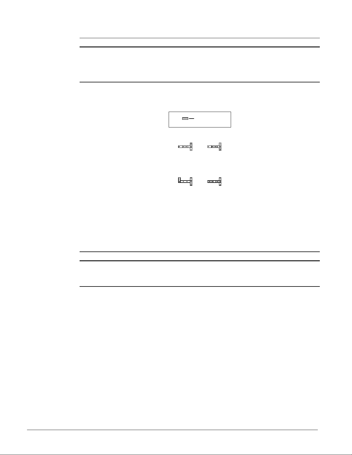
Table 2. Signal Selector Current/Voltage Outputs
Current / Voltage Input Impedance
0–5 VDC
0–10 VDC
0–5 mA
0–20 mA
350
700
1000
250
Ω
Ω
Ω
Ω
Figure 1. Signal Selector Jumpering
Jumper
0-5 VDC 0-10 VDC
0-5 mA 0-20 mA
Address Switch
The address switch distinguishes each AOX-4 board in a daisy-chain. The number on the address
switch corresponds to a group of four analog outputs. Each board should have a unique address
switch position, which will provide the appropriate output numbering (see Table 3).
Table 3. Address Switch Numbering
AOX-4 Board Number Address Switch Number Analog Output
1 0 0–3
2 1 4–7
3 2 8–11
Power Diagnostic LEDs
The power diagnostic LEDs are used to monitor power on the AOX-4 boards. The green LED (OK)
indicates when power is normal. The red LED (BAD) indicates that power is normal, but a current
overload is present on the board.
If the red LED illuminates, remove the wires from each analog output port until the LED
extinguishes. If the LED remains lit after removing all the wires from the analog output ports, remove
the ribbon cable connecting the AOX-4 to the MCB. If the LED remains lit after removing the ribbon
cable, the AOX-4 board is defective and needs replacing.
26-Pin Expansion Bus Connectors
The 26-pin expansion bus connectors connect via a ribbon cable to the expansion bus connector of
the MCB or to other AOX-4 boards in a daisy-chain. There are two 26-pin expansion bus connectors
on each AOX-4 board. If more than one AOX-4 board is being used, the first board’s 26-pin
expansion bus connector (J7) is connected to the MCB with a ribbon cable. The second 26-pin
2 IM 607-1
 Loading...