

Cleveland 6-CDM Service Manual

UNITED STATES
CANADA
Cleveland Range
REPAIR MANUAL
Model No.
6/9CEM18/27/36/48
6/9CGM100/200/250/300
6/9CDM
6/9CSM
Cleveland Range, Inc.
1333 East 179th St.
Cleveland, Ohio 44110
Phone: (216) 481-4900 • FAX: (216) 481-3782
Garland Commercial Ranges • 1777 Kamato Rd.
Mississauga, Ontario CN L4W 1X4
Phone: (416) 624-0260 • FAX: (416) 624-0623
FCS-05
INSTALLATION INSTRUCTIONS
CONVECTION
MODULAR
KETTLES ON
UNITED STATES
CANADA
for
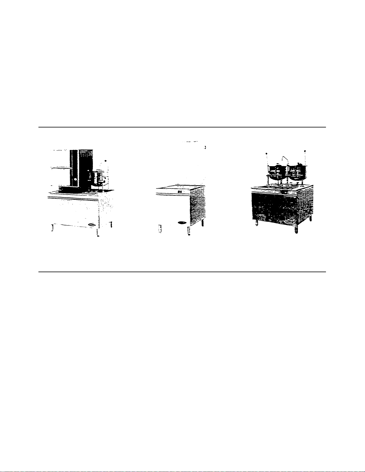
STEAMERS, STEAMER/KETTLES,
MODULAR BOILER BASES, and
KETTLES ON BOILER BASES
STEAMER with
KETTLE
BOILER
Cleveland Range, Inc.
1333 East 179th St.
Cleveland, Ohio 44110
Phone: (216) 481-4900 - Telex: 98-0546 • FAX: (216) 481-3782
BOILER BASE
BASE
Garland Commercial Ranges • 1177 Kamato Rd.
Mississauga, Ontario CN L4W 1X4
Phone: (416) 624-0260 • FAX: (416) 624-0623

INSTALLATION INSTRUCTIONS FOR
STEAMERS, STEAMER/KETTLES, MODULAR BOILER BASES, and
KETTLES ON BOILER BASES
FOR YOUR SAFETY
Do not store or use gasoline or other flammable vapors
and liquids in the vicinity of this or any other appliance.
WARNING
Installation of this equipment must be accomplished by qualified installation personnel.
working to all applicable local and national codes. Improper installation of this product could
cause injury or damage.
Cleveland Range equipment is designed and built to compl y with applicable standards for manufacturers. Included among those
certification agencies which have approved the safety of the equipment design and construction are: UL. A.G.A., NSF, ASME,
CSA, CGA, and others.
Cleveland Range equipment is designed and certified for safe operation only when permanently installed in accordance with
local and/or national codes. Many local codes exist, and it is the responsibility of the owner and installer to comply with these
codes.
In no event shall Cleveland Range assume any liability for consequential damage or injury resulting from installations which are
not in strict compliance with our installation instructions. Specifically, Cleveland Range will not assume any liability for damage
or injury resulting from improper installation of equipment, including, but not limited to, temporary or mobile installations.
INSTALLATION INSTRUCTIONS FOR ALL MODELS
1. These instructions must be retained by the owner/user for future reference. Gas-fired boilers are only to be installed in
noncombustible areas that have provisions for adequate air supply. The term "boiler" will be used synonymously with "steam
generator."
WARNING
The flooring that will be directly under the boiler, must also be made of a noncombustible material.
2. Position: For proper operation and drainage, the equipment must be level. It should be placed next to an open floor drain. DO
NOT POSITION THE UNIT DIRECTLY ABOVE THE FLOOR DRAIN. Observe all clearance requirements to provide air
supply for proper operation, as well as sufficient clearance for servicing. The surrounding area must be free and clear of
combustibles. Dimensions and clearance specifications are shown on the specification sheet.
3. Install in accordance with local codes and/or the National Electric Code ANSI/NFPA No. 70-1987. Installation in Canada must
be in accordance with the Canadian Electrical Code CSA Standard C22.1. Equipment that is connected to electrici ty must be
grounded by the installer. A wiring diagram is provided inside the base cabinet
4- The drain line outlet discharges exhaust steam and hot condensate. Connect 11/2" IPS piping (or larger) to extend the drain line
to a nearby open floor drain. Up to two elbows and six feet of 11/2" IPS (or larger) extension pipe should be connected to the
drain termination. Drain piping extended six to twelve feet, or using three elbows, should be increased to 2" IPS. No more than
two pieces of Cleveland Range equipment should be connected to one common drain line. The maximum length of extension
from the drain termination should not exceed six feet and use no more than two elbows. The extension piping must have a
gravity flow and vent freely to the air. This drain outlet must be free-vented to avoid the creation of back pressure in the steamer
cooking compartments. To ensure a vented drain line. DO NOT, UNDER ANY CIRCUMSTANCES. CONNECT THE DRAIN
OUTLET DIRECTLY TO THE FLOOR DRAIN OR SEWER LINE. Do not run the drain line discharge into PVC drain piping
or any other drain piping material not capable of sust aining 180°F operation.
FAILURE TO OBSERVE THESE REQUIREMENTS CAN RESULT IN DAMAGE TO EQUIPMENT AND/OR THE POSSIBILITY OF INJURY
(Continued on next page)

• Direct-steam connected pressure steamers do not require a cold water connection, and therefore steps #5 and #6 do not
apply. Refer directly to step #7. A kettle fill faucet, if-so equipped, requires a hot and/or cold water connection. The data
contained in step #5 for cold water also applies to hot water.
5. Connect COLD water supply plumbing to the line strainer. (Never connect hot water to the boiler's water fill line strainer).
Constant flow pressure must be maintained between 35 and 60 psi, and not experience a pressure drop below 35 psi when
other appliances are used. If the water pressure exceeds 60 psi, a pressure reducing valve must be installed in the water supply
plumbing to reduce the water pressure to less than 60 psi. Locations and pressure data are shown on the specification sheet.
1/4" IPS plumbing is sufficient for water supply lines up to 20 feet in length, but water supply lines longer than 20 feet should
be at least 3/8" IPS. Rush water supply lines thoroughly before connecting them to the unit. Use water which is low in total
dissolved solids content and low in gas content to prevent internal scaling, pitting and corrosion of the steam generator, and
carry-over of minerals into the steam. Water which is fit to drink can still contain highly detrimental impurities.
NOTE: If equipped with a kettle and kettle water fill swing spout, 3/8" (10mm) hot and/or cold water connection(s) will be
required at the swing spout's Valve-6, Turn on the cold water supply to the unit. Ensure that the manual water valve, inside the
base cabinet. is open.
7. Connect the primary fuel supply in accordance with the following instructions. Location and other data are shown on the
specification sheet.
For Gas-Fired Steam Generators:
Post, in a prominent location, instructions to be followed in the event the user smells gas. This information shall be obtained
by consulting the local gas supplier. Install a sediment trap (drip leg) in the gas supply line, then connect gas supply piping to
the boiler's gas valve piping. GAS-FIRED EQUIPMENT IS DESIGNED FOR INSTALLATION ONLY IN NONCOMBUSTIBLE LOCATIONS. THIS INCLUDES THE FLOORING THAT WILL BE DIRECTLY UNDER THE
EQUIPMENT. Location, plumbing size, and pressure data are shown on the specification sheet. Boilers rated at less than
225.000 BTU require 3/4" IPS gas supply piping, and boilers rated at 225.000 BTU or more require 1" IPS gas supply piping.
Natural gas supply pressure must be between 4" -14" water column, and LP. gas supply pressure must be between 12" - 14"
water column. NEVER EXCEED 14" WATER COLUMN (1/2 psi) GAS PRESSURE. If the gas supply pressure exceeds
14'' water column, a pressure regulating valve must be installed in the gas supply plumbing to reduce the gas pressure to less
than 14" water column. Installation must be in accordance with local codes, or in the absence of local codes, with the National
Fuel Gas Code, ANSI Z223.1-1984. Installation in Canada must be in accordance with Installation Codes for Gas Burning
Appliances and Equipment B149.1 and B149.2. Use a gas pipe joint compound which is resistant to LP gas. Turn the gas
valve's control knob to "on" (the word "on" on the knob will be opposite the index on the valve's body). Test all pipe joints for
leaks with soap and water solution. Never obstruct the flow of combustion and ventilation air. Observe all clearance
requirements to provide adequate air openings into the combustion chamber. The appliance and its individual shut-off valve
must be disconnected from the gas supply piping system during any pressure testing of that system at test pressures in excess
of 1/2 psi (14" water column or 3.45 kPa). The appliance must be isolated from the gas supply piping system at test pressures
equal to or less than 1/2 psi (14" water column or 3.45 kPa). A permanent 115 volt electrical connection is required at the
junction box. The junction box location is shown on the specification sheet. The unit must be electrically grounded by the
installer.
For Electric-Powered Steam Generators:
Connect electric power location and date are shown on the specification sheet. Provide connection as required by your unit:
either directly to the single contactor, or to the terminal block (when equipped with multiple contactors). Electric supply must
match power requirements specified on the data plate inside the base cabinet. The copper wiri
ng must be adequate to carry the required current at the rated voltage. A separate fused disconnect switch must be supplied and
installed. The unit must be electrically grounded by the installer.
For Steam Coil Steam Generators:
Connect steam supply piping to the input side of the steam coil. Location and pressure data are shown on the specification
sheet- Incoming steam pressure must be regulated between 35 and 45 psi. A 3/4" strainer, equipped with a 20 mesh stainless
steel screen, must be supplied and installed at the incoming steam connection point Rush the steam line thoroughly before
connecting it to the boiler. To ensure an adequate volume of steam, the branch steam supply line must be 3/4" IPS minimum.
Connect the inverted bucket trap to the outlet end of the steam coil. Fill the trap with water before installing it. A permanent
115 volt electrical connection is required at the junction box. The junction box location is shown on the specification sheet.
The unit must be electrically grounded by the installer.
For Direct -Steam-Connected Steamers/Kettles:
Connect steam supply piping to the input side of the line strainer. Location and pressure data are shown on the specification
sheet. Rush the steam line thoroughly before connecting it to the steamer. To ensure an adequate volume of steam. the branch
steam supply line must be 3/4" IPS minimum. (Direct-steam-connected kettles require 1/2" IPS pipe if the kettle's total
capacity is 20 gallons or less, and 3/4" IPS pipe if the total capacity exceeds 20 gallons.) A permanent 115 volt electrical
connection is required at the junction box. The junction box location is shown on the specification sheet. The unit must be
electrically grounded by the installer. (Note: pressure steamers equipped with strictly manual steam and drain valves do not
require an electrical connection.)
(Continued on reverse side)
(Continued)
8. Press the top of the power on-off rocker switch. The red indicator light in the switch will come on and the boiler will
begin to fill with water.
• Direct-steam-connected steamers are not equipped with self-generating boilers or "steam" switches. Therefore, these models
do not require the 5-minute boiler water fill time, nor is it necessary to push a "steam" switch to produce steam, as indicated
in step #9. As soon as the pressure gauge on the control panel registers 10 psi (5 psi for pressur e steamers), preheating may
begin. If you are operating a direct-steam-connected steamer, steps #9 and #10 do not apply. Refer directly to step #11.
9. After about five minutes, the amber light in the "steam'' switch will glow, indicating the water has reached a safe operating
level in the boiler. The "steam" switch can now be pressed (momentarily) in order to produce steam in the boiler. This will
activate the energy source (electric heaters, gas burners, or steam solenoid valve), and the amber light will go out. The energy
source cannot be activated until the boiler contains sufficient water, indicated by the amber light. The "steam" switch must be
pushed to re-start the steamer after it is shut off for any reason (including a momentary power interruption). Do not attempt to
start or operate this appliance during a power failure. Whenever the amber light is illuminated, the healer, steam supply, or
burners are off, and no steam is being generated- (Note: for units containing gas-fired boilers only: if the burners fail to ignite
in four seconds, a safety circuit will de-energize the system. In this event, momentarily press the power switch to the "off"
position, then back to the "on" position. The "steam" switch amber light should be on. Wait 5 minutes, then press the "steam"
switch to start the burner ignition cycle once again.)
10. Check to ensure that the water in the boiler's sight gauge glass automatically stays about 1/3 full when the boiler is started up
and operated.
11. Check to ensure that the steam pressure gauge registers 10 psi (5 psi for pressure steamers).
The steam pressure is factory-adjusted to provide the proper pressure. In some cases, however, the factory setting may shift due
to shaking in transit, and resetting will be required after installation. Proper adjustments and maintenance procedures are
detailed on a separate data sheet entitled "Steam Pressure Adjustments." Adjustments should be made only by qualified service
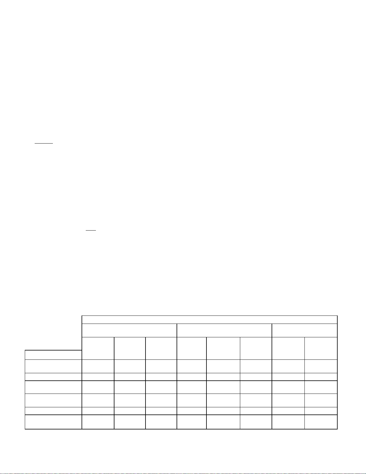
personnel. The factory pressure settings shown in the accompanying chart should never be exceeded.
12. When the installation is complete and free of leaks, refer to the Operating Procedures page, in order to check for proper
operation of the unit.
Equipment
Steam Generator Only
5 psi
Pressure Steamer N/A 5 psi 10 psi 5 psi 10 psi 30-45 psi 5 psi 12-45 psi
Pressure Steamer With Any
Kettle(S)
Steam Generator Only 10 psi N/A 10 psi 15 psi 10 psi 15 psi 30-45 psi N/A N/A
Kettle Only —At N/A 10 psi 15 psi N/A N/A N/A N/A 5-45 psi
Convection Steamer with or
Without Kettles
GAUGE PRESSURE R READING WITH NO STEAM PLOW (STOIC PRESSURE)
Self-Contained Steam Generator Gas or Electric Self-contained Steam Coil Generator Direct-Connect (To "House" Steam
Steamer's
Pressure
Reducing Valve
N/A 5 psi 10 psi 5psi
5 ps i
N/A 10 psi 15 pa 10 psi 15 psi 35-45 psi 10 pa 15-45 OS
Operating
Pressure Switch
10 psi 15 psi 5 psi
High Limit
Safety Pressure
Switch
Operating
Pressure
Switch
High Limit Safety
Pressure Switch
10 ps i
10 ps i
Steam Supply
Pressure Range
30-45 psi N/A N/A
30-45 psi 5 psi 12-45 pa
Supply)
Steamer's
Pressure
Reducing Valve
Steam Supply
Pressure Range
2SO-TR (R2)0388
'Kettles are to be connected to the "house" steam supply

Data Sheet 260-TY
CLEVELAND CONVECTION STEAMER (MODEL C) OPERATING INSTRUCTIONS
Operation of the Cleveland Convection Steamer is very easy Each operator should read and understand the following procedures to effectively
start, operate, and shutdown the steamer each day.
Start-up and Preheat:
1- Check the cooking compartments to ensure that the steam tubes and drain screens are in place and secure. Check inside the steamer's base
cabinet to ensure that the manual drain valve is closed and the manual water supply valve is open.
2. Press the top of the power on-off rocker switch located at the lower left of the control panel, under the steam pressure gauge. The red indicator
Iight in the switch will come on and the boiler will begin to fill with water.
• Direct-steam-connected steamers are not equipped with self-generating boilers or "steam" switches. Therefore, these models
do not require the 5 minute boiler water fill time. nor is it necessary to push a "steam" switch to produce steam, as indicated in
step #3 below. As soon as the pressure gauge on the control panel registers 10 psi. preheating may begin. If you are
3. After about five minutes, the amber light in me "STEAM" switch will glow, indicating the water has reached a safe operating level in the boiler.
The "STEAM" switch can now be pressed (momentarily) in order to produce steam in the boiler. This will activate the energy source (electric
heaters. gas burners, or steam solenoid valve), and the amber light will go out The energy source cannot be activated until the boiler contains
sufficient water, indicated by the amber light. The "STEAM" switch must be pressed to restart the steamer after it is shut off for any reason
(including a momentary power interruption). No attempt should be made to operate the equipment during a power failure. Whenever the amber
Iight is illuminated, the heaters, steam supply, or burners are off, and no steam is being generated. (Note tor steamers containing, gas-fired
boilers only if the burners tail to ignite in four seconds, a safety circuit will de-energize the system. In this event, momentarily press the power
switch to the "off" position, then back to the "on" position. The "STEAM" switch's amber light should be on. Wait 5 minutes, then press the
"STEAM" switch to start burner ignition cycle once again.) In about 20 minutes the steam pressure gauge on the control panel should register
10 psi.
4. You can now preheat the cooking compartment(s). Cooking compartments should always be preheated before cooking.
NOTE: With a steamer/kettle combination, if both must be used at the same time, always heat the kettle first When kettle contents begin to
simmer and steam pressure returns the steamer compartments may be preheated.
5. To preheat close the compartment door by gently swinging it shut Set the electronic digital timer for one minute, in accordance with the
following timer setting instructions. It will be several minutes before the time display begins to count down. When the preheating is completed,
me steam will automatically shut off and a tour second alarm will sound.
operating a direct-steam-connected steamer. "skip" step #3. and refer directly to step #4.
Timer Setting:
Each Convection Steamer compartment is equipped with an independent electronic digital timer, which has a maximum setting of 99 minutes.
Each timer is connected to a temperature sensing device in the cooking compartment. THIS SENSOR WILL ALLOW THE TIMER TO COUNT
DOWN ONLY
will use, as the timer automatically compensates for food product defrosting and/or heat-up time.
The timer can be set when the "COOKING TIME" display shows "00" (double zeros) which are illuminated continuously (not flashing). The two
small. square pads below the timer display are pressed to set the timer. Press 1 to set one to nine (and zero) minutes for units digits (single
minutes). Press 10 to set ten to ninety minutes for ten's digit (multiples of ten minutes). Pressing continuously on either pad causes the digits to
change at a rate of digits per second. If you pass the correct digit, continue pressing the pad. The display will cycle from "9" back to "O." then
continue upward again.
The timer is activated (and steam enters the cooking compartment} when the "START/ cancel pad is pressed. Red LED- lights glow in the upperleft comer of the pad and the lower-right corner of the time display when the timer is activated. REMEMBER, THE TIMER WILL BEGIN TO
COUNT DOWN ONLY AFTER THE COMPARTMENT REACHES PROPER COOKING TEMPERATURE. When the timer is counting down, the
red LED. light continuously flashes on and off at the lower-right corner of the display. Once the pre-set time has counted down to zero, an alarm
will sound for four seconds and the timer display will continuously flash "00" until the "start/CANCEL" pad is pressed. Once the timer is activated,
the time cannot be changed unless the "start/CANCEL" pad is pressed. Once pressed. the pad's LED will go out, any remaining time in the timer
will be cancelled, and the display will show "00 — not flashing, A new time setting can now be entered into the timer display.
EXAMPLE: To cook for 14 minutes: Press the "start/CANCEL" pad to be sure the timer display shows "00" and is not flashing. Press the 10 then
release it when the "1" appears in the display. Press the 1 and release it when the "4" appears in the display. Press the "START/cancel pad to
start the timer (note the illuminated red LED.'s in the pad and the time display). When the display counts down to zero. a tour second alarm will
sound, and the display will flash "00" (the LED.'s will go out}. Press the "start/CANCEL" pad to reset the timer, shown by continuously illuminated
"00" in the display (not flashing).
Automatic Cooking Operation:
To cook, place a pan of food in the compartment, set the desired cooking time and press the "START/ cancel" pad The timer will delay.
automatically compensating lor defrosting and/or food product heat-up time. If you have set the timer at 10 minutes, it may in fact take 11 on 2
minutes for the set
When the display counts down to zero. the four second alarm will sound, and the display will flash "00" (the LED's will go out). Press the
"start/CANCEL" pad to reset the timer, shown by continuously illuminated "00" in the display.
Manual Cooking Operation:
If a cooking cycle longer than 99 minutes is desired, do not use the timer. Just press the "MANUAL OPERATION" pad. located below the timer, to
start the flow of steam. You must press the pad again to shut off the steam. A red LED light in the upper-left comer of the pad illuminates nates
when the manual mode is activated and steam is flowing into the cooking compartment. THE TIMER CAN BE USED DURING THIS TIME. IT WILL
OPERATES AS STATED. EXCEPT IT WILL NOT TURN OFF THE STEAM AFTER THE ALARM SOUNDS.
The door may be opened for food inspection anytime during the cooking cycle, but KEEP HANDS OUT OF THE COOKING COMPARTMENT TO
PREVENT BURNS. Optimum steam heat transfer, and therefore a higher quality food product is achieved when shallow perforated uncovered
pans are used.
Boiler Shutdown:
The red-lighted power switch must be shut off for 3 minutes a minimum of once every 8 hours to automatically drain highly mineralized water from
the boiler, which reduces the formation of scale.
Data—Sheet—26EO (R1)
2 44098
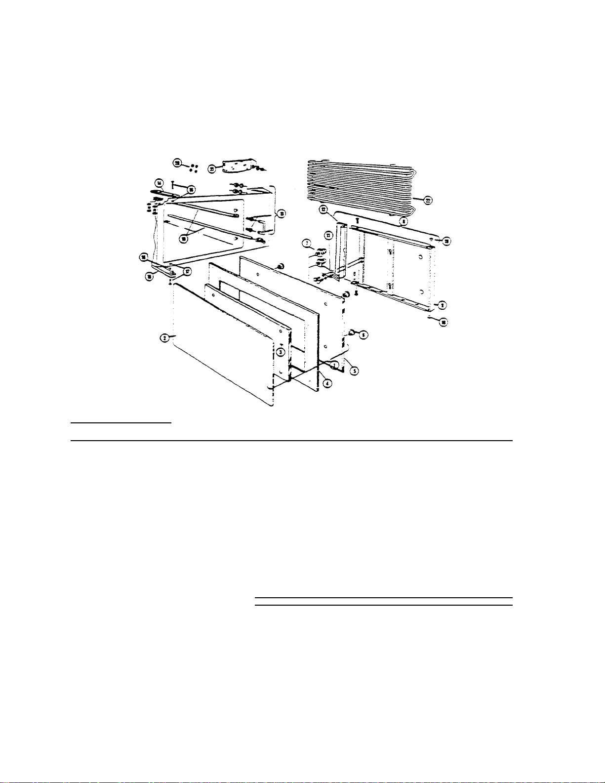
Gasket Retainer Plate
3 68214
Inner Gasket Retainer Plate
4
07138
Gasket
5
04171
Inner Door
6
14687
Knurled Finger Nut. 1/4
-20 7
68508
Inner Door Mounting Stud
8
44087
Outer Door Assembly
9 44088
Outer Door Weldment
10 02089
Bushing
(2
required)
11
69629
Door Spring
12
44167
Door Latch Assembly
58113
Door Latch (less plastic insert
&
screws)
70638
Plastic
Insert (not shown)
19152
Pivot Screw
(2
required)
13
40878
Door Catch Assembly
14 58178
Upper Hinge Bracket (lower if door is hinged right
15 58179
Lower Hinge Bracket (upper if door a hinge
d right)
17 40884
Lower Hinge Pin and Retainer (upper if door is hinged right)
18 19552
Spacer
19
40783
Steam Tube
20 15203
"0"
Ring
(4
required)
21 69298
Drain Screen (After Dec.
1
. 1983)
69233
Drain Screen (Before Dec.
1. 1983
) 22 41423
Slide Rack
CONVECTION STEAMER MECHANICAL COMPONENTS
(Solid State Model "C" with Touch Control Timer Panel)
REFERENCE NUMBER PART NUMBER DESCRIPTION
1 44090 Inner Door Assembly
CLEVELAND RANGE, INC., 1333 EAST 179th ST., CLEVELAND, OHIO 44110
Manufacturer reserves right of design improvement or modification, as warranted.
LITHO IN U.S-A.
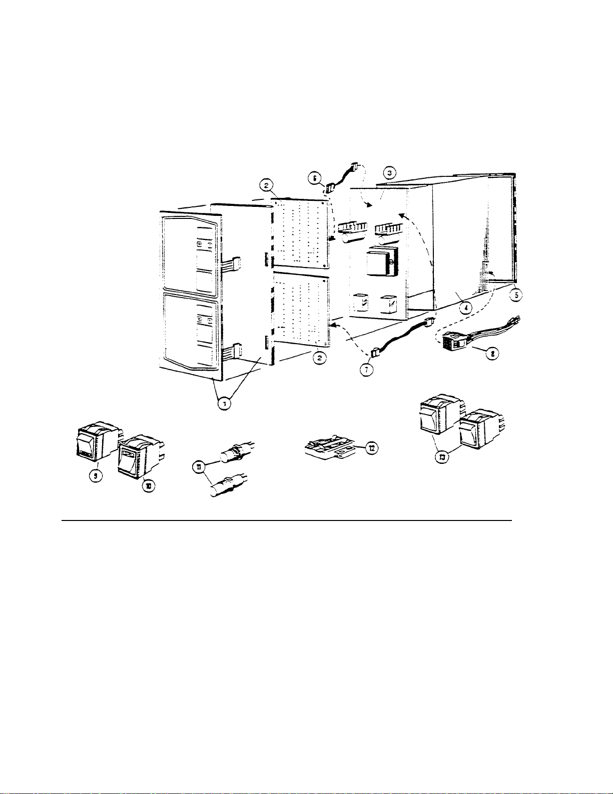
CONVECTION STEAMER ELECTRICAL COMPONENTS
(Solid State Model "C" with Touch Control Timer Panel
Data Sheet 261
REFERENCE NUMBER PART NUMBER DESCRIPTION
1 45005 Control Panel (Membrane Switch)
2 20479 Solid State Timer
3 16652 Power Supply Board
4 52595 Instrument Panel Enclosure
5 56228 Instrument Panei Frame
6 03002 9" Cable Assembly
7 03003 14" Cable Assembly
8 08135 Wire Harness
9 19993 DPDT Power Switch
10 19994 SPST Momentary Contact Reset Switch
11 19972 Thermostatic Switch
12 44168 Terminal Block 2 pole
13 19992 DPDT Rocker Switch Emergency Bypass
CLEVELAND RANGE , INC., 1333 EAST 179th ST., CLEVELAND, OHIO 44110
Manufacturer reserves right of design improvement or modification, as warranted.
LITHO IN U.S.A.
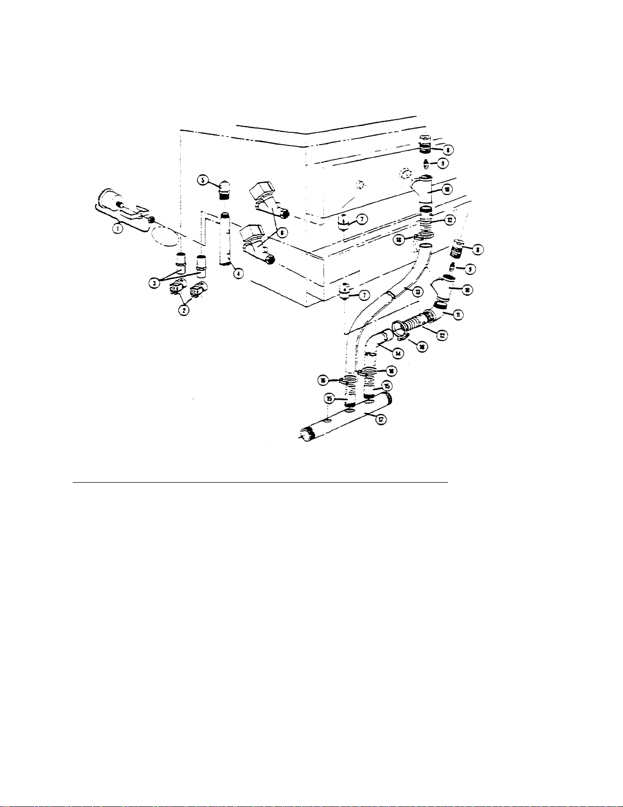
CONVECTION STEAMER PIPING COMPONENTS
2 22218 Water Solenoid Valve
4
13301 Steam Manifold
9 14555 Nozzle. Jet, Steam Condenser
10
02139 1"
"Y"
1
1
16 03180 Hose Clamp
(Solid State Model "C" with Touch Control Tuner Panel)
REFERENCE NUMBER PART
NUMBER
1 07168 Pressure Gauge
3 15455 Plow Regulator. 1/2 GPM
5 22226 Air Vent
6 22224 Steam Solenoid Valve
7 20559 Thermostatic Trap
8 06230 Reducing Bushing for Nozzle
05227 1" Street Elbow
12 56519 Compartment Drain Fitting (2 holes)
13 70743 Tubing, 39" long
14 70742 Tubing, 28" long
15 14481 Combination Hose Fitting (no holes)
17 13252 Drain Manifold
DESCRIPTION
CLEVELAND RANGE, INC., 1333 EAST 179th ST., CLEVELAND, OHIO 44110
Manufacturer reserves right of design improvement or modification. as warranted.
LITHO IN U.S.A.

SERVICE GUIDE FOR CLEVELAND CONVECTION STEAMER SOLID STATE
COMPARTMENT CONTROLS
Read the following instructions to familiarize yourself with the solid state timer components and their functions. Once familiar with the
operation, refer to the troubleshooting guide when on the job site (to diagnose the problem), then refer back to the instructions for specific
tests.
The solid state compartment control system for Cleveland Range Steamers is designed for easy service. No special tools or technical
training is required to troubleshoot and repair these controls. A suggested list of required tools is as follows:
1. Screwdriver (blade type)
2. 1/4" or 5/16" nut driver
3. V.O.M. or multimeter
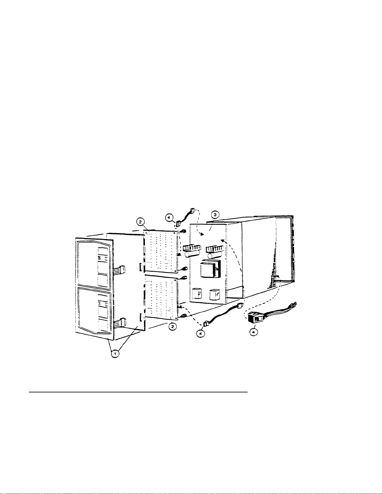
Refer to Figures #1 and #2. The system contains 4 basic components: (1) control pane! (45005). (2) two solid state timers (20479), (3)
power supply board (1 6652). (4) interconnecting cables and harness (03002,03002,08135). Each of these four parts will be discussed in detail.
Solenoids and manual bypass switches will not be covered in this guide. All of these parts, except #08135, are assembled in one enclosure
(40833) that can be removed easily from the front of the steamer.
The Convection Steamer cooking compartments are controlled by a low voltage solid state system that provides both
timed and manual operation of the cooking compartments-All wiring connections to the timer system are provided through a multipin
connector that is part of the power supply board. The wiring harness is equipped with the mating pan for the connector.
The power supply board provides 24 VDC to power the output relay coils and the alarm. 5 VDC for the timer and logic power, and 5.5
VAC to provide clock pulses to the timers. The stepdown transformer is mounted to the power supply board. Also on this board are two DPDT
relays (one for each compartment) which are used to switch 120 VAC on and off to the compartment steam and water solenoid valves. A 4second piezo type alarm mounted on the power supply board is used to signal the steamer operator at the end of the cooking cycle.
Each solid state timer is wired to the power supply board by a cable assembly and to the control panel by a ribbon connector. These timer
boards are equipped with LED displays to indicate cooking time and operating mode. Compartment thermostatic switches are wired to the
timers through the power supply board and cable assemblies, and operate at 5 VDC. These thermostatic switches (normally open. then close at
193° F) are used to activate the timers when the compartments reach cooking temperature. Each timer board and thermostatic switch
independently controls a single compartment
The control panel contains the membrane type switches which provide 5 VDC command signals to the timer boards. The metal backing
plate is used to mount the two timer boards-Two DPDT emergency bypass switches (one for each compartment) are provided, with the switch
"commons" connected to the load. Both switches should normally remain in the "run" position. With a switch in the "run" position, the
appropriate steam and water solenoid valves will be operated by the control system described above. In the event of a failure in the solid state
compartment control system, the system can be bypassed by placing one or both switches in the "bypass" position. With a switch in the bypass
position, the appropriate steam and water solenoid valves will be energized continuously. Each switch can be used to manually operate a
cooking compartment until the control system is repaired.
CONTROL PANEL (MEMBRANE SWITCH)
The control panel (45005) consists of a membrane switch panel bonded to a stainless steel backing plate. This metal plate is also used to
mount the two solid state timer boards (20479). All control panel switches are normally open momentary contact, pressure sensitive
membrane type switches. All control panel switches operate at 5 VDC. Each switch is used to provide a command signal to the timer boards.
The switch circuitry for each compartment is separate from the other compartment. Two separate connectors, (one for each compartment),
are used to connect the switches to the timer boards. This separation allows one compartment to work even if control switches of the other
compartment are damaged. If pressing a control switch of one compartment causes the control of the other compartment to respond, the
control panel (membrane switch) is defective or damaged.
The switch panel can be tested individually by continuity testing. Refer to figure #3. With none of the switches being pressed, there should
be no continuity between any two pins of the connector. When checking an individual switch, there should be continuity between the common
pin and the designated pin of the switch only when the switch is

pressed. Check to be sure that no other pins show continuity to "common" except the pin of the switch being pressed.
CAUTION: When checking continuity, it is best to use a VOM or multimeter, as higher lamp currents of some
continuity testers may damage the switch contacts. Resistance reading should be less than 50 ohms. DO NOT
use AC line voltage or DC voltages above 5 VDC.
Check for damaged or abraided ribbon connectors that may cause shorting to the metal of the control enclosure If
necessary, insulate the ribbon by placing black electrician's tape along the tracer side of the ribbon connector
SOLID STATE TIMER BOARD
Complete testing of the timer board in the kitchen may be impractical. However, knowing the functions which are
exclusive to the timer board, accurate diagnosis of failures can be made.
The following functions are performed by each timer board:
1 Cooking time entry and storage.
2 Display of cooking time remaining.
3. Count down (timing) when the compartment thermostatic switch is closed.
4 Energizing the output relay during cooking cycles (manual and timed).
5. Manual on/off control of the compartment.
6. Sounding the alarm for four seconds at the end of the cooking cycle.
7. Display of operating mode (manual and/or timed).
8. Flashing display digits after the end of the timed cooking cycle.
Although the other components in the control system are necessary for proper operation, they are only support or
interface hardware for these timer boards.
All logic and operating sequences are the direct functions of the timer boards.
Generally, failures that affect the operation of both compartments are not associated with the timer boards, as each
timer board independently controls a single compartment. When there is trouble with the operation of one compartment
control only. simple tests made by switching wire cables at the power supply board, or swapping timer boards, are
helpful in pinpointing a defective unit. As an example, if a serviceman found that the upper compartment's controls did
not switch on the solenoid valves for that compartment, he may proceed as follows. First with the steamer power off,
the interconnecting cables (03002 and 03003) could be interchanged at the power supply board. With the steamer's
power restored, if the same compartment failed to operate, this would indicate a problem with the power supply board,
wire harness (08135), or solenoid valves. If the symptoms changed from the upper compartment to the lower, then the
fault is in the timer board or control panel. The control panel may be tested individually as described in the "Control
Panel Section, or it can be tested by swapping the timer boards - To do this, interchange the upper and lower timer
boards and connect the wire cables in their original, correct order. If, after changing the boards (and installing cables
correctly), the upper compartment still does not work, then the control panel is at fault On the other hand. if the
symptoms changed from the upper compartment to the lower, then the fault is in the timer board now mounted on the
bottom. Due to the simple wiring and mounting design of the solid state controls, these types of tests can often be done
faster than testing with meters or special test set -ups.
POWER SUPPLY BOARD
The basic function of the power supply board is as an interface between the 120 VAC control system of the steamer
and the low voltage (5 VDC) circuits of the timers All connections to the board are provided by polarized multi-pin cable
or harness connectors
A simplified schematic of the board is shown in figure #4. The power supply, including transformer, is
powered by 120 volts AC. and provides 3 output voltages:
1 5 volts DC to power the solid state timers and digital displays. 2- 24
volts DC to power output relay coils and the alarms. 3. 5.5 volts AC to
provide clock pulses to the timers.
The 5 volt and 24 volt DC outputs of the power supply are equipped with LED indicators to aid in troubleshooting. In
normal operation, these LED's should be illuminated any time power (120 VAC) is supplied to the board. If there is no
output voltage from the 5 volt DC and/or 24 volt DC supplies, then the corresponding LED will not be fit. In addition,
both the 5 volt and the 24 volt DC supplies are protected against short circuits. If there is a short circuit, the vo ltage
regulator of the affected supply will shut down and the indicating LED for that supply will not be fit. This feature can be
useful in determining the location of a short circuit. Disconnect the cable connectors at the power supply board to
determine if the
short circuit is in a timer board or a cable connector. It the LED illuminates when the cable connectors are disconnected. a timer
board or cable connector is snorted. NOTE: The power supply regulators are thermally protected and may be overheated. In this
case, the regulators require time to reset to their "on" condition before they allow the LEDs to illuminate.) Reconnecting the cable
connectors one at a time will indicate which timer board (or cable) is snorted, as the LED will not be lit when the defective board's
cable is reconnected To determine if the short circuit is in a cable connector, disconnect each cable from the timer boards, then
connect each cable, one at a time, to the power supply board. The LED wilt not be lit when the defective cable is reconnected.
The actual output voltages may be measured between "Common" and the cable connector pins. as shown in figure #4. (pin # = 5
VDC. pin #7 = 5.5 VAC. alarm's solder joint labeled "+1" = 24 VDC).
The output relays are used to switch 20 volts AC on and off to the steam and water solenoid valves of the compartments. The
relay coils (24 VDC) need only a "common" connection to operate. In normal operation me "common" path is provided by the
timer boards (20479). To test the relays, shut off the power to the steamer at the main on/off switch. Disconnect the wiring cable
assemblies (03002 and 03003) from the power supply board, and remove the control panel- Connect a jumper from pin #2 to pin
#4 of each cable connector (on the power supply board). Restore power to the steamer. The relays should close upon application
of power.
A similar test can be used to test the alarm. Jumping pin #3 to pin #4 of either cable connector will cause the alarm to sound.
FIGURE 1 COMPARTMENT CONTROL BOX COMPONENTS
REFERENCE
NUMBER
1 45005 Control Panel (Membrane Switch)
2 20479 Solid State Timer
3 16652 Power Supply Board
4 03002 9" Cable Assembly
4 03003 14" Cable Assembly
4 08135 Wire Harness
PART
NUMBER
DESCRIPTION
 Loading...