

Page 1

Cleo Steam Brain
Item no: 90179999
EN2018/0 9 R01
Installation manual
EN
Page 2

Cleopatra B.V.
Oostzijde 295
1508 EN Zaandam
Netherlands
www.cleopatra.nl
www.cleopatra-wellness.com
[email protected]
Copyright
All information in this technical document, together with the drawings and technical specifications made
available by Cleopatra B.V., remain the property of Cleopatra B.V. and may not be copied without
permission. Cleopatra B.V. reserves the right to make changes in the interest of further developments.
Up to date on: 01- 01-2019
2
Page 3

Table of contents
Installation manual
1 Introduction and safety ..................................................................................................................4
2 Warnings ............................................................................................................................... 5
3 Required tools and materials .......................................................................................................... 6
4 Overview steam generator ............................................................................................................. 7
5 Steam generator dimensions........................................................................................................... 8
6 Installation in the technical area ...................................................................................................... 9
7 Mounting on the wall.....................................................................................................................9
8 Water connection and waste water ...............................................................................................11
9 Electrical connection ....................................................................................................................12
9.1 Next steps: electrical connections ......................................................................................13
10 Steam pipe .............................................................................................................................14
11 Overview of sensors .................................................................................................................... 15
12 Overview operation .................................................................................................................... 15
13 Overview of steam inlet ............................................................................................................... 16
14 Placing components in the cabin ................................................................................................... 16
14.1 Explanation recess holes ...................................................................................................17
14.2 Explanation laying cables ................................................................................................. 18
15 Finishing ............................................................................................................................. 19
15.1 Placing sensors ................................................................................................................20
15.2 Placing steam outlet ......................................................................................................... 22
15.3 Installation of control ........................................................................................................23
16 Removing the control ...................................................................................................................25
17 Overview of electrical connections ................................................................................................ 26
17.1 Connecting electronics Brain .............................................................................................26
17.1.a Connecting electronics Brain - option white light .................................................... 28
17.2 Connecting Multimedia Module .........................................................................................30
17.3 Connection LED spots module ...........................................................................................32
17.4 Connection LED rails module ............................................................................................ 34
18 Electrical connections ..................................................................................................................36
19 Declaration of conformity ............................................................................................................. 39
3
Page 4
1 Introduction and safety
These instructions are intented for the installer. Read these instructions carefully to get to know the product, the
parts and the installation method. The Cleo Steam Brain must be installed by qualified and well-trained personnel.
The Cleo Steam Brain complies with the applicable standards and regulations and does not pose any direct
danger for the user if the Cleo Steam Brain is installed according to the manufacturer’s instructions and is used in
accordance with this manual. The electronic and mechanical parts must be carefully maintained so that the Cleo
Steam Brain remains fully operational. For this reason, the instructions must be followed closely.
All information and instructions in this manual have been compiled in accordance to the applicable standards and
regulations, the current technique and our years of experience and findings. National and local regulations must
be followed.
Check the product for possible transport damage. After the installation, a claim for (surface) damage will not be
accepted by Cleopatra.
Every right to warranty expires if adjustments have been made to the original product or parts. This manual must
be kept close to the product for quick access if needed.
Important instruction or description
Use screws and plugs to mount the Cleo Steam Brain on the wall. Walls that support the Cleo Steam Brain must
be strong enough to carry the weight; otherwise they need to be strengthened. The supplied plugs and screws are
intended for use on concrete or solid stone walls. If the walls are made of a different material than concrete or
solid stones, use material that is suitable for that specific wall. (not included in delivery).
Cleopatra accepts no liability for damage caused by:
- Failure to follow the manual.
- Wrong use.
- Installation by unqualified personnel.
- Unauthorized changes to the product.
- Technical changes.
- The use of non-original spare parts.
Correct use:
- The Cleo Steam Brain may only be used indoors.
- Use in another way is not permitted and is for the user’s own risk.
- Do not use the Cleo Steam Brain when it is not in perfect condition.
- Do not use this product in an environment where it is exposed to corrosion.
Pay attention: General danger
4
Page 5
2 Warnings
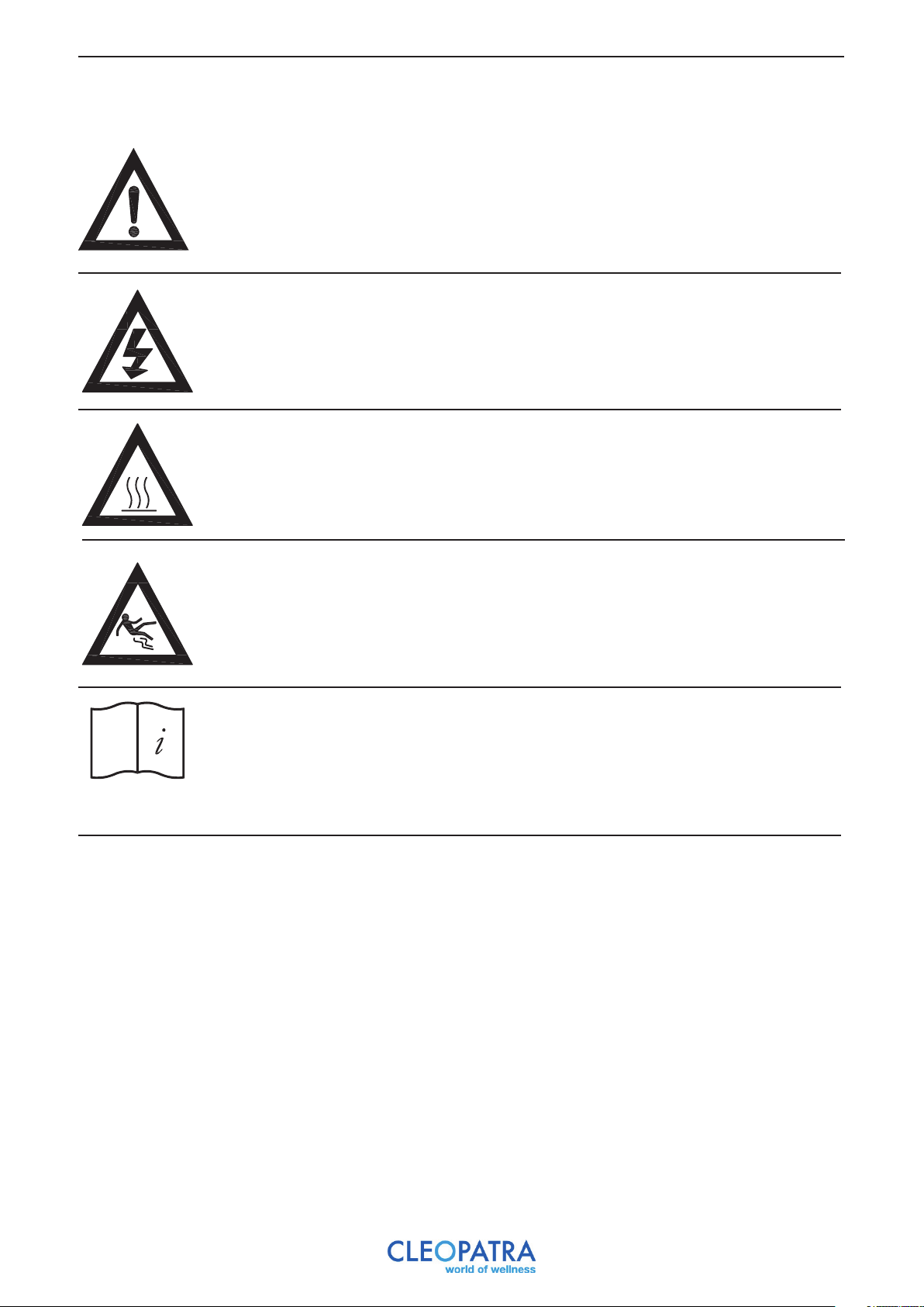
Without permission and without instructions, the use of a steam cabin is
forbidden for the following persons:
- Children.
- Adults with disabilities.
- Persons who have not been instructed about what a steam cabin is
meant for.
- Persons who are intoxicated.
Bringing electrical devices in the cabin is forbidden!
Warning hot surfaces.
The steam inlet, the surrounding area and the steam itself are very hot. Do not touch them
because of danger of injuries.
Warning for slipping.
The floor of the cabin can be slippery.
Read the user manual carefully before using the steam cabin!
Maximum time to stay in the cabin: 15 min
Humidity in the cabin: max. 10 0%
Maximum temperature in the cabin: 45-48 ˚C
5
Page 6
3 Required tools and materials
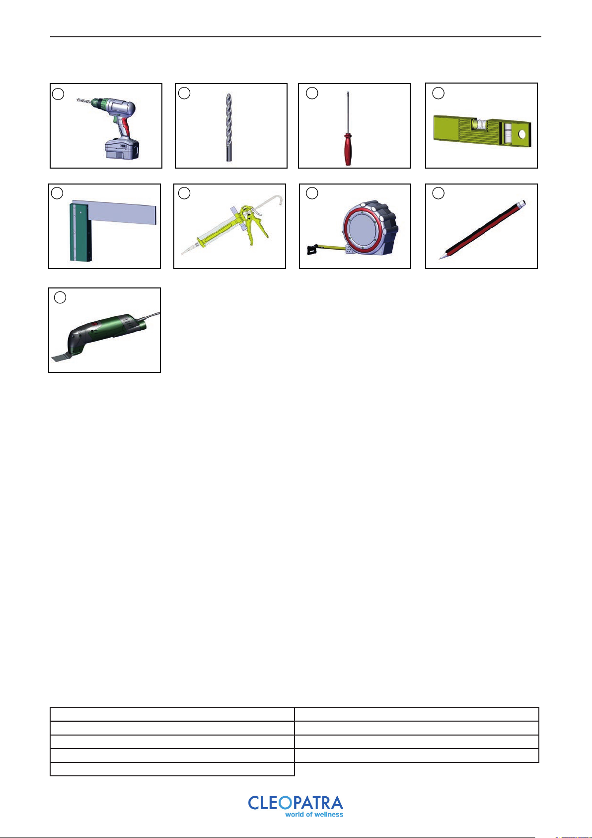
1
2 3
4
6 75 8
9
2: Drill set
3: Screwdriver (cross)
4: Spirit level
5: Square
6: Kit gun 1: Drill
7: Tapeline
8: Pencil
9: Multitool
6
Page 7
4 Overview steam generator
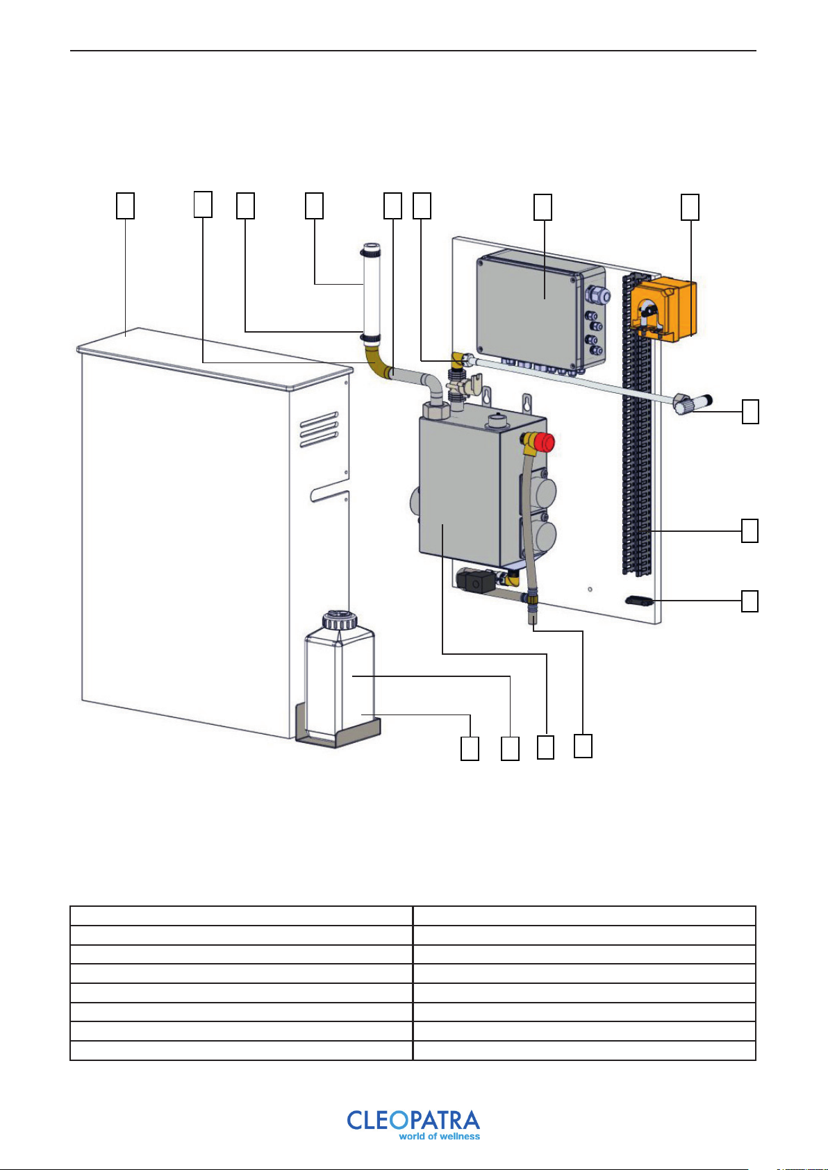
B
A
C
D
F
E
G
H
I
J
K
A: Casing
B: Steam outlet knee fitting
C: Hose clamp
D: Flexible hose
E: Steam outlet
F: Water pipe
G: Control box
H: Fragrance pump*
*Only applicable with the optional fragrance dispenser
L
O N
I: Water pipe tap
J: Cable tray
K: Cable clamp
L: Drain (DO NOT DEFORM)
M: Steam generator
N: Fragrance reservoir*
O: Fragrance reservoir holder*
M
7
Page 8
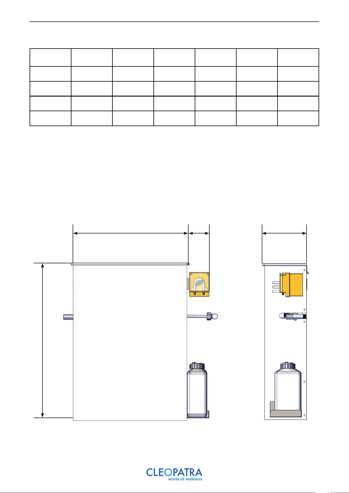
5 Steam generator dimensions
Power
(kW)
3 532 710 190 90 +/-17 kg
4.5 532 710 190 90 +/-17 kg
6 532 710 190 90 +/-17 kg
9 532 710 190 90 +/-17 kg
A
(mm)
B
(mm)
*Only applicable with the optional fragrance dispenser
C
(mm)
D*
(mm)
Weight
(kg)
Steam outlet
(Ø)
22
22
22
28
A
B
D
C
8
Page 9
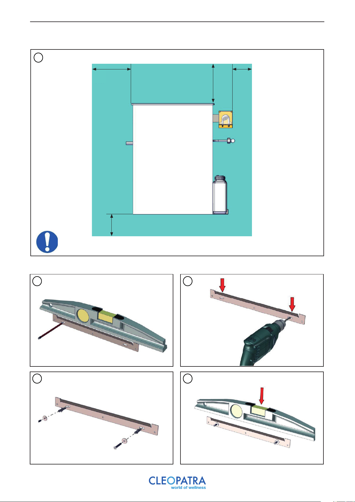
6 Installation in the technical area
1
200 mm
X: Space for water drainage and siphon
X
200 mm
100 mm
Use the minimum distances as shown in the drawing.
7 Mounting on the wall
1
3 4
2
9
Page 10
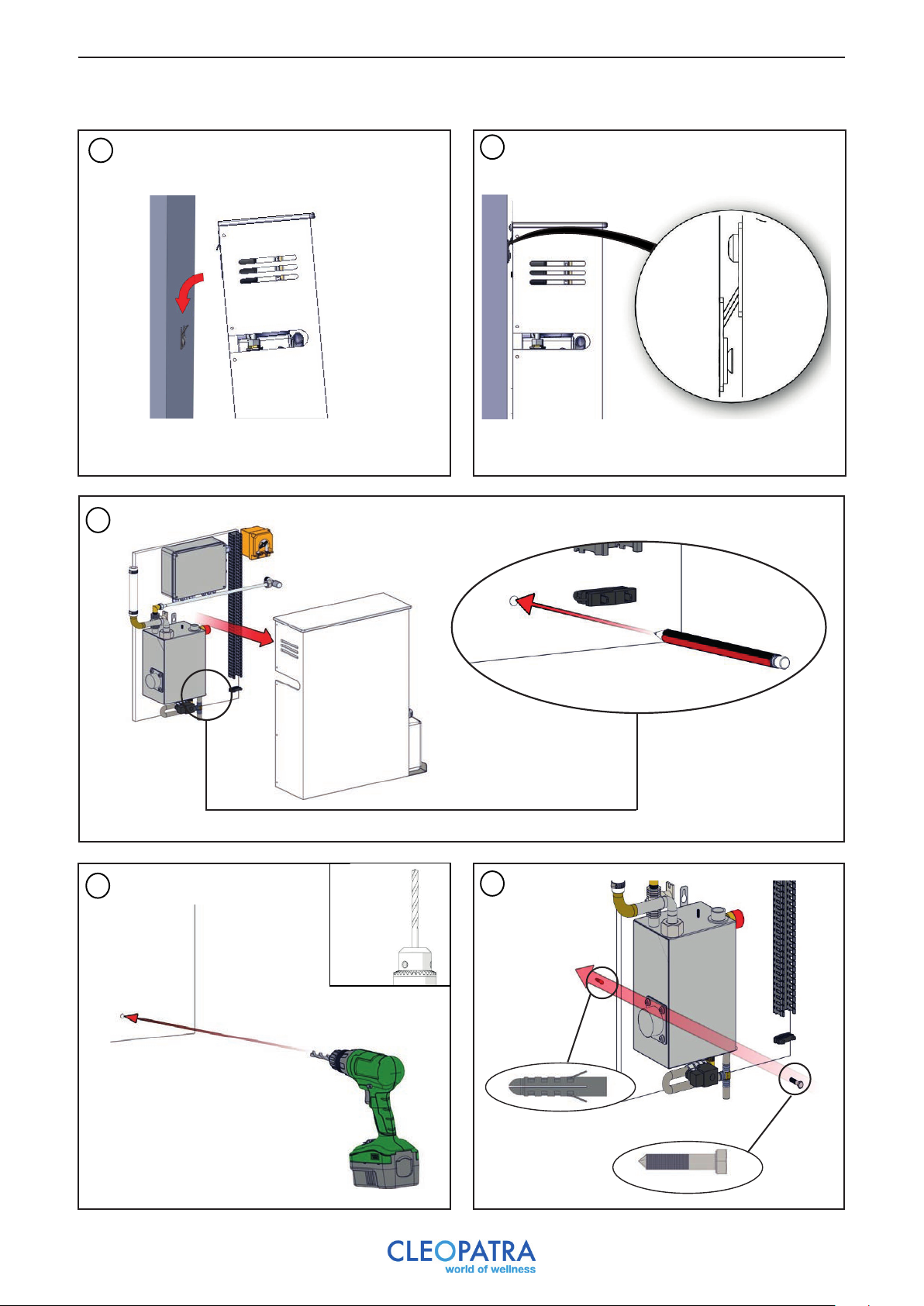
5
7
6
8
8mm
9
m8
10
Page 11

8 Water connection and waste water
Maximum water pressure: 10 bar / 1 MPa
Water pressure when working: max. 1 bar
Water temperature: min. 5 ˚C
Recommended water temperature: < 20 ˚C
Connections: G 1/2 external
Desired installation conditions:
- Maximum ambient temperature: + 40 ˚C
- Minimum ambient temperature: + 5 ˚C
- Maximum humidity: 80% not condensing
- Main voltage: -8% + 10% P
- Maximum pressure steam cylinder exit: 100 mm water
Water quality: The Cleo Steam Brain generators can use both hard and soft water.
Recommended is untreated tap water.
Water hardness: The water hardness is measured to the international Millimol / l calcium and
magnesium ions per liter (former DH).
Soft water: < 1.3 mmol/l
Medium hard water: 1.3 - 2.5 mmol/l > 7 DH
Hard water: 2.5 - 3.8 mmol/l > 14 DH
Very hard water: > 3.8 mmol/l > 21 DH
The water drainage must be brought to the drain.
1
2
Drain
Air Air
Drain
Air must flow freely into the drain.
11
Page 12
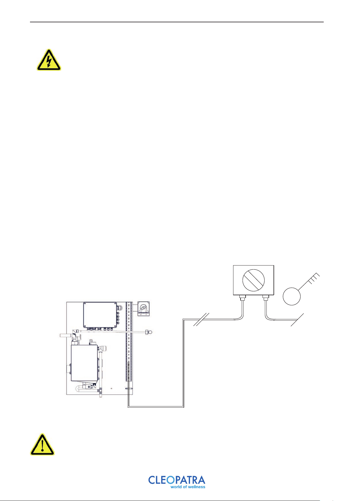
9 Electrical connection
The electrical connection may only be carried out by a qualified electrician. For the electrical
installation the current applicable VDE, country specific and EU regulations must be observed.
All installation and test activities must be carried out by a qualified electrician and according to the latest
standards. Electrical outlets must be equiped with a breaker. The electricity network (230 VAC 50Hz or 400 VAC
50 Hz) to which components are connected must be equipped with a 30 mA fault current protector (earth
leakage breaker), as stated in the DIN EN 60335-2-41 / VDE 0700 standard. If the electrical connection cable is
damaged, it must be replaced. Turn off the power before you start working.
Local regulations must be observed. The steam generator must be installed in an area intended for this purpose.
This area must be equipped with adequate ventilation. During installation, a multi-pole main switch must be
installed with a contact distance of at least 3 mm.
The steam bath generator belongs to “Protection class I” (electrical divices) and must be connected via an earth
leakage breaker. The steam generator must be connected correct in the same way as all Class I devices.
Components that have a higher voltage than 12V must be installed out of reach of people for safety reasons. The
electricity scheme is attached. All connections must be done according to this scheme, respecting all regional and
national regulations. The work may only be carried out by a qualified electrician.
In the electrical scheme the maximum connection value of the external components is shown. These values may
not be exceeded. No modification may be made to the original wiring. External components may only be
connected to the appropriate clamps.
Circuit breaker
(Not included in delivery)
Electricity supply 230 / 400 V
Connect all cables in accordance with NEN 1010.
12
Page 13
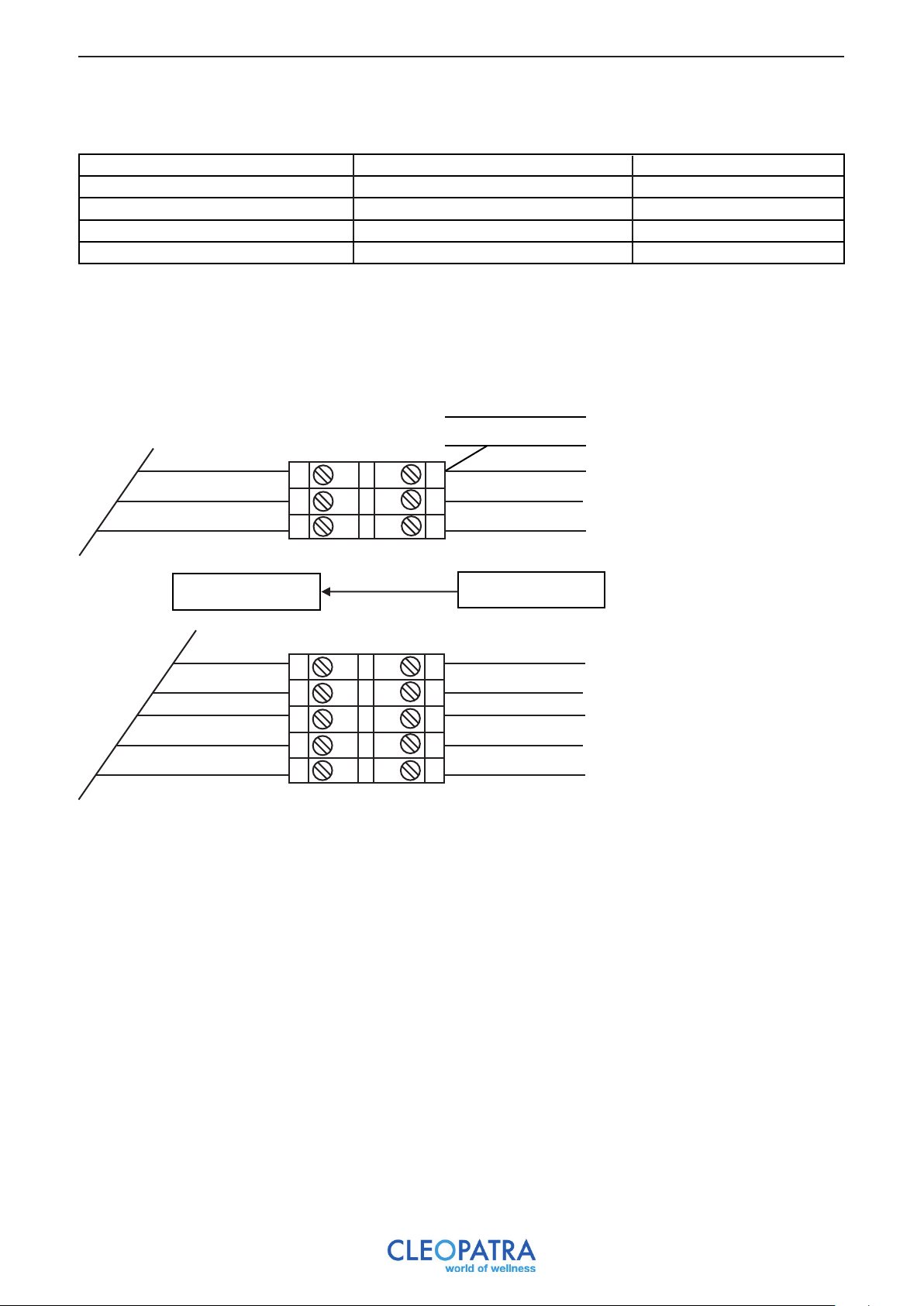
9.1 Next steps: electrical connections
Overview of electrical connections.
Power Connection Electricity
3 kW 230VAC-1N-50/60Hz 13A
4.5 kW 400VAC-1N-50/60Hz 13A
6 kW 400VAC-1N-50/60Hz 13A
9 kW 400VAC-1N-50/60Hz 13A
A power cable of +/- 2 meters is included and connected.
Connect the Cleo Steam Brain to the power supply according to the scheme below:
Junction box
Shutting down
Shutting down
L1
N
PE
L3
L2
L1
N
PE
L1
N
PE
L3
L2
L1
N
PE
Grey
Black
Brown
Blue
Yellow/Green
Generator
Grey
Black
Brown
Blue
Yellow/Green
3 kW
4.5/6/9 kW
13
Page 14
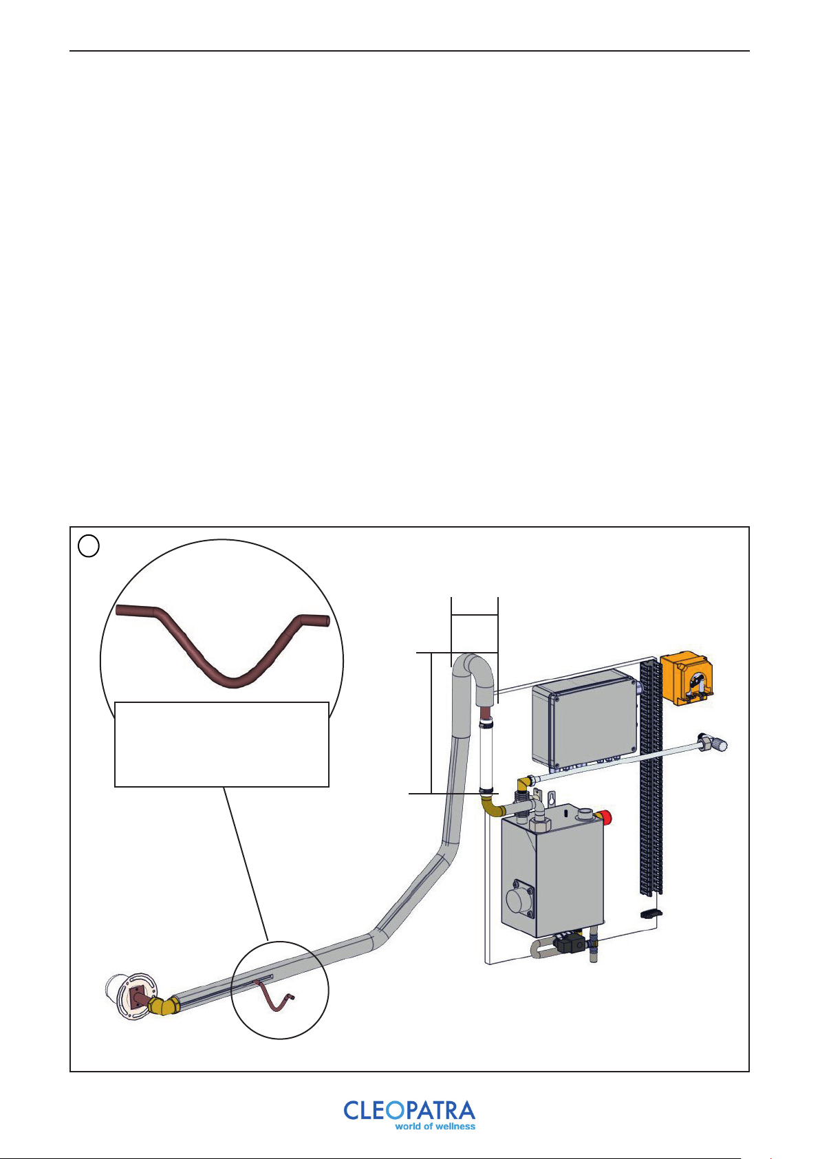
10 Steam pipe
The steam pipe must always be made of an isolated copper pipe with a specified minimum diameter. This is 22
mm for generators up to 6 kW. At 9 kW a pipe diameter of 28 mm is used. The steam line is connected to the
generator by means of the supplied rubber, steam hose and the supplied brass bend. It is forbidden to use knees
in the steam pipe. All bends must be carried out with a minimum radius of 50 mm. A knee is only used for the
direct steam inlet in the cabin.
The steam pipe must always be placed at least 600 mm upwards to prevent the flow of hot water drops. The
maximum length of a steam pipe is 3 meters. Make sure the steam pipe runs down to two sides: the steam outlet
and the steam generator. In this way no so-called ‘saggers’ are created, so that gurgling noises can not arise from
stagnant water.
When the installation is provided with a fragrance dispenser, make sure that this pipe does not have any ‘sagger’
in which fragrance remains. For the quality and longtivity of the fragrance it is important that it can flow
directly downwards to the inlet piece. A small ‘curved siphon’ (see drawing) in the inlet piece guarantees the
correct operation.
1
> 50 mm
Euca / Fragrance connection
piece preferably near the
steam inlet and accessible
> 600 mm
14
Page 15
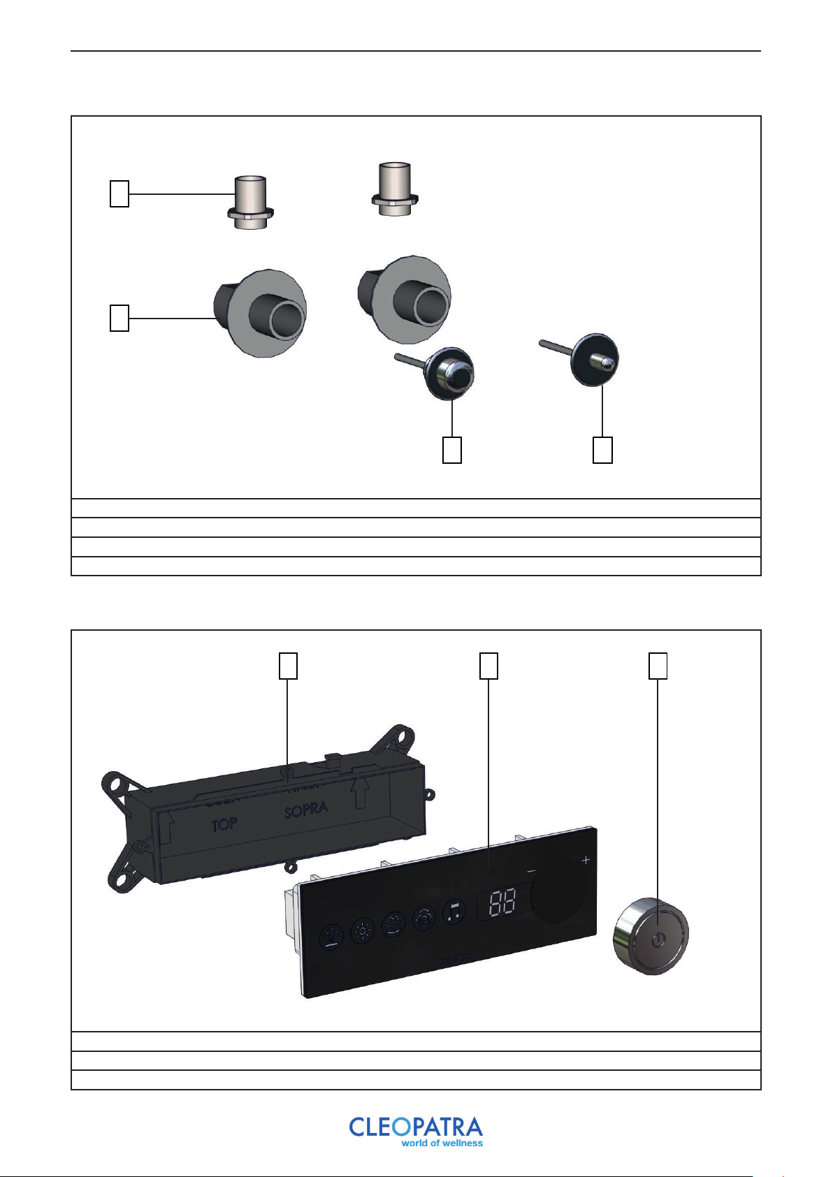
11 Overview of sensors
A
B
C D
A: Tube input for the purpose of putting in flexible tube
B: Built-in part sensor
C: Safety sensor
D: Temperature sensor
12 Overview operation
A CB
A: iBox for Steam Brain
B: Steam Brain control
C: Rotary knob Steam Brain
10107100
10107000
10107200
15
Page 16
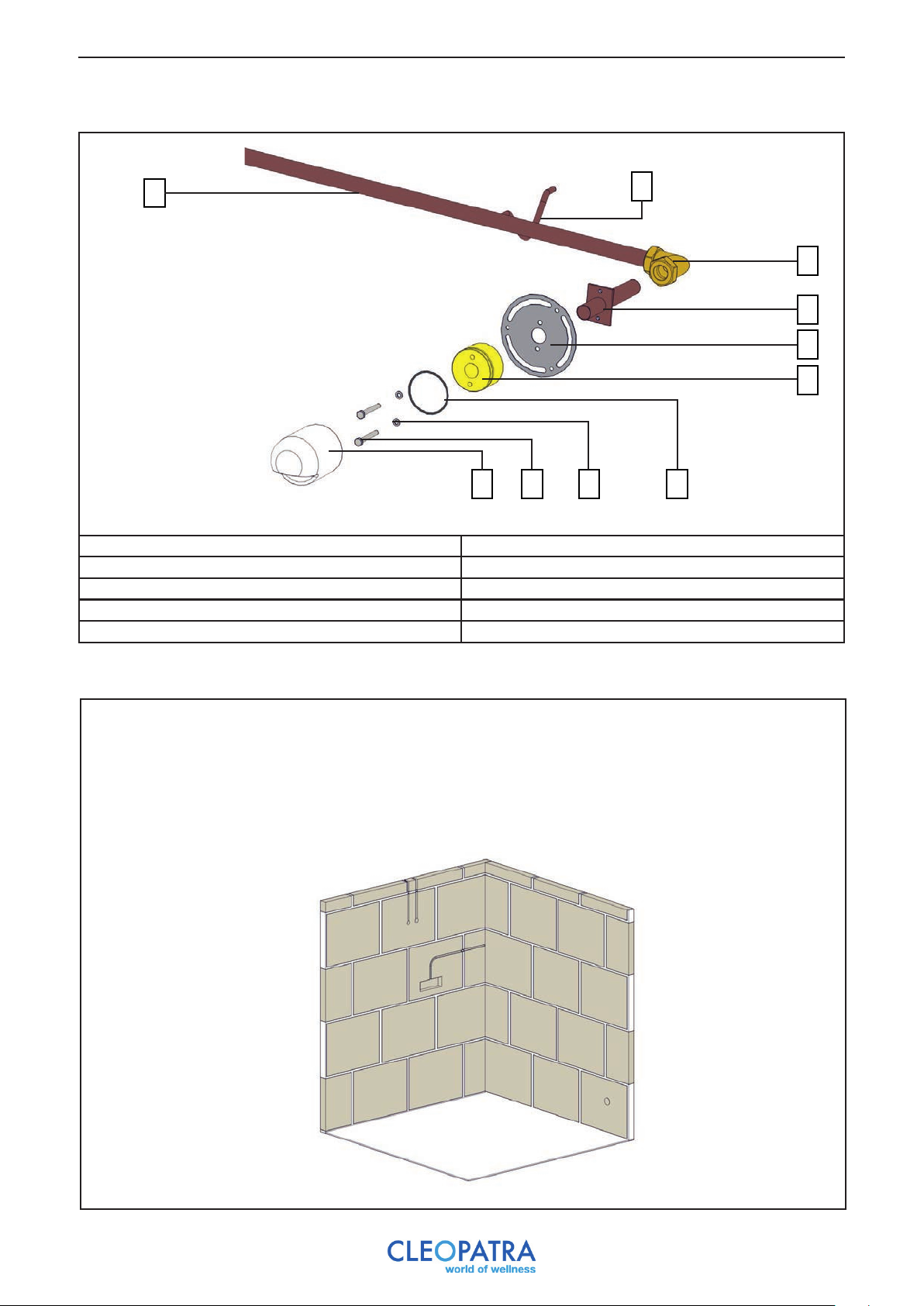
13 Overview of steam inlet
A
A: Brass pipe Ø 22mm
B: Siphon for fragrance application
C: Knee piece
D: Coupling tube
E: Wall plate
J
F: Steam outlet
G: O-ring
H: Ring m6
I: Bolt m6x50
J: Steam hood
I H
B
C
D
E
F
G
14 Placing components in the cabin
To make clear how the components can be placed in a cabin, we give an example. The cabin in the
example is made up of aerated concrete blocks.
First indicate the position of the various components and then cut the recesses as they are
indicated.
16
Page 17
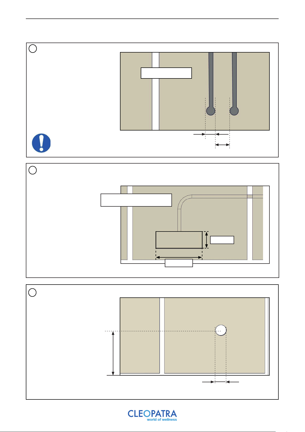
14.1 Explanation recess holes
1
Drill two recesses for the pipes
(for the cables) and the built-in
parts for the safety sensor and
the temperature sensor.
Sensors should be placed 1.8
meters from the floor surface
Min. depth: 40mm
Always keep a radius of 100 mm
around a sensor.
Drill two recesses for the
2
pipes (for the cables) and
the built-in part for the control.
Drill a recess for the pipe for the
3
steam inlet.
Ø 35mm
Min. 100mm
Min. depth: 50mm
95 mm
260 mm
Min. 150 mm
Max. 180 mm
from the floor
surface
Min. 70 mm
17
Page 18
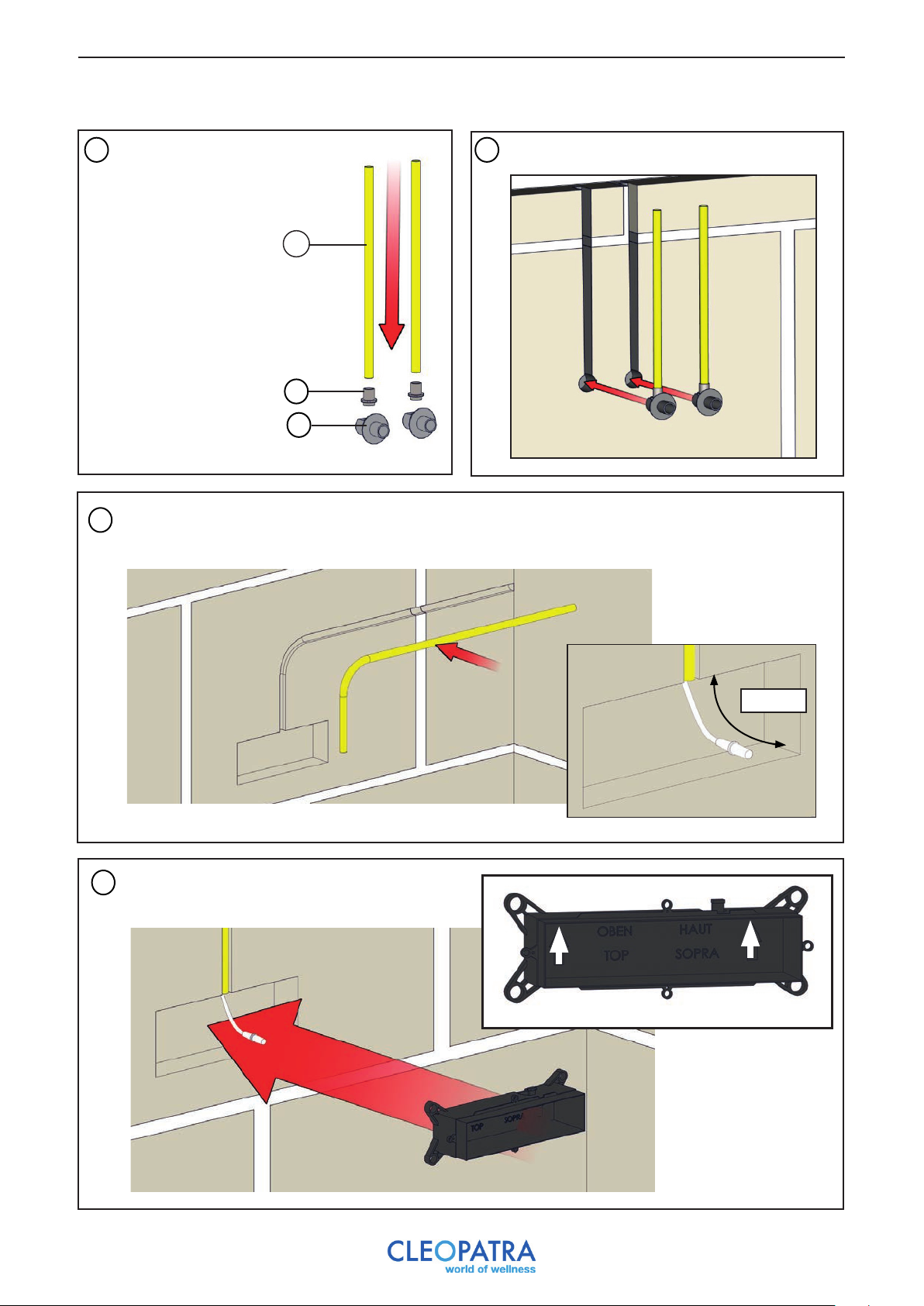
14.2 Explanation laying cables
Assemble 2x:
1
1 Built-in part sensor
2 Tube input
3 Cable tube
3
2
1
Pull the extension cable through the cable tube to the steam generator.
3
Make sure there is at least 10 cm of play in the cable.
2
Place the piping of the steam inlet through the
4
milled hole.
Guide the cable through the hole in the template.
10 cm
Pay attention!
18
Page 19
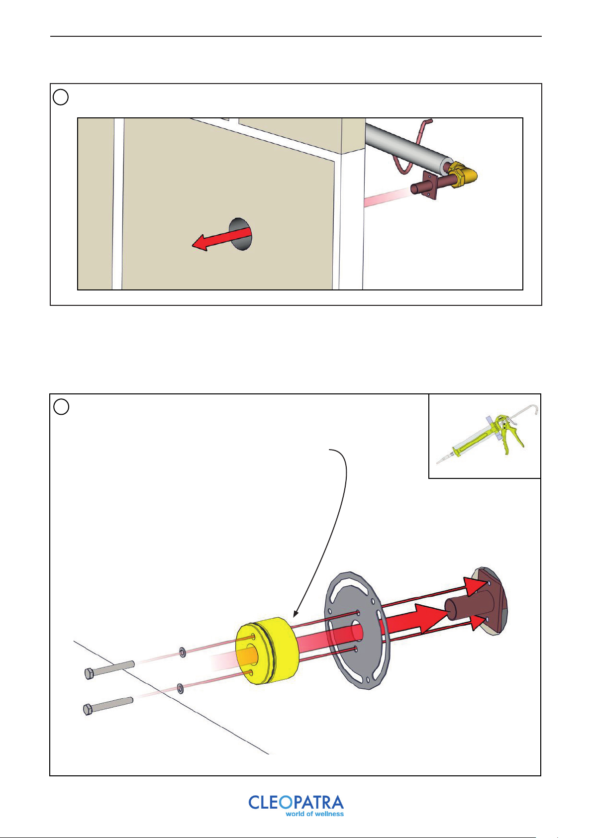
5
Place the piping of the steam inlet through the recess.
15 Finishing
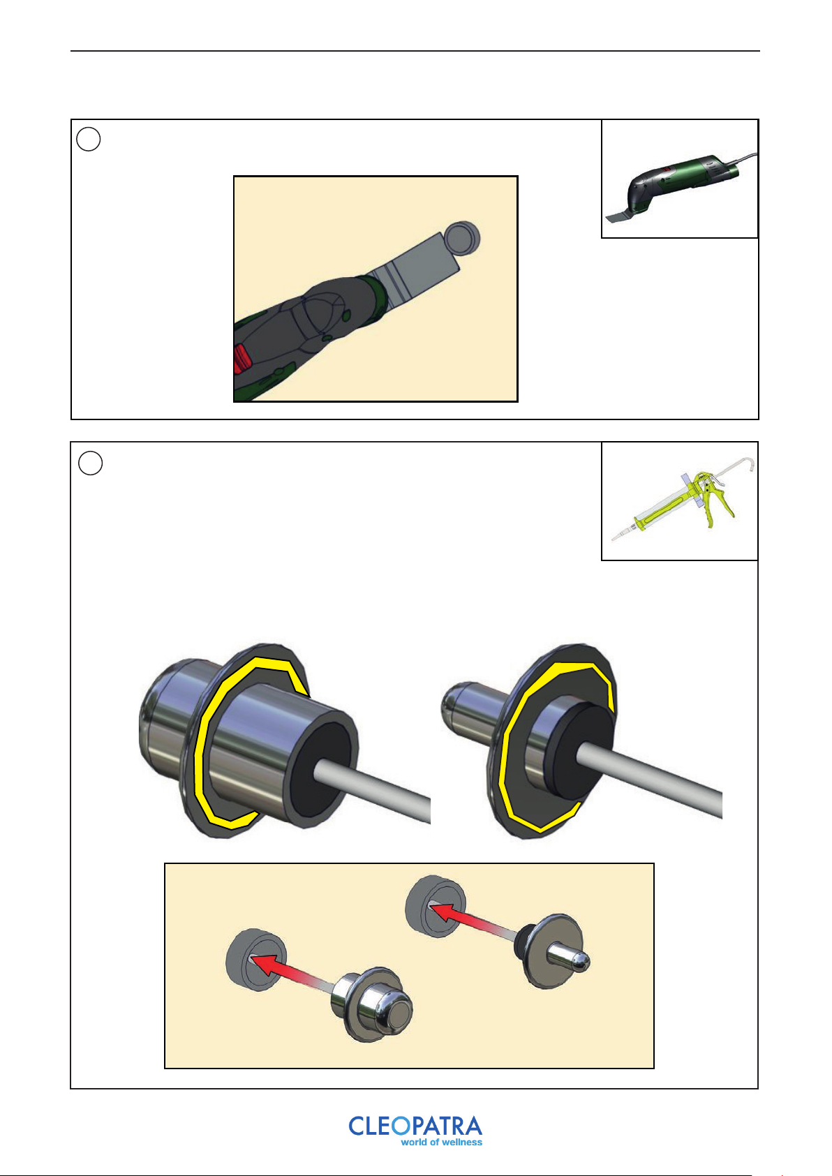
When finishing the walls, part of the steam outlet must be placed after plastering is done.
Next, tile the rest of the room to install the remaining parts.
Stuc de wand
Plaster the wall and attach the steam outlet with o-ring to the wall plate.
1
Provide the back of the steam outlet with kit.
19
Page 20
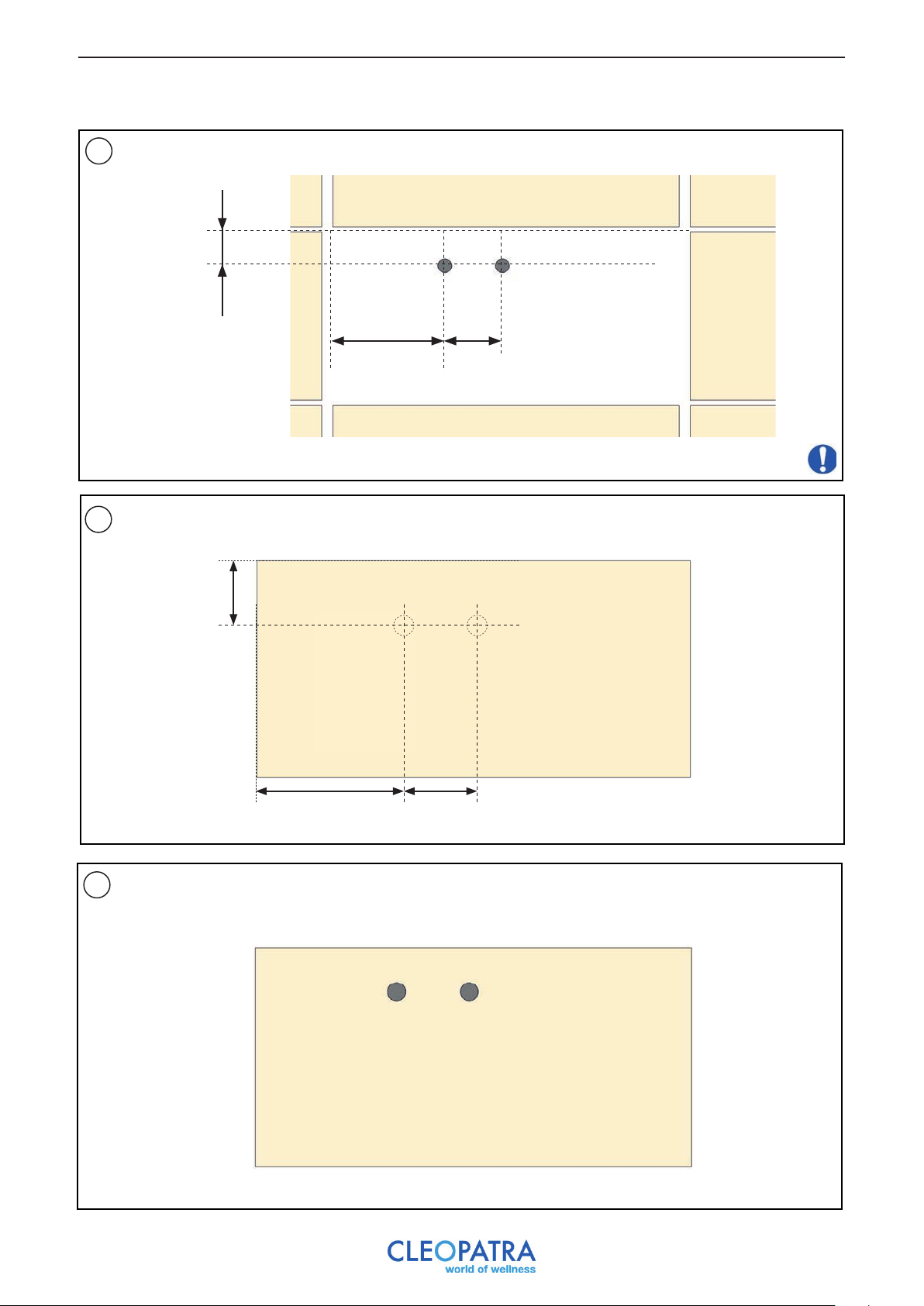
15.1 Placing sensors
Measure the distances to the center lines of the hole.
1
61 m m
2
Measure and mark these distances on the tile.
100 mm194 mm
All distances serve as an example
61 mm
100 mm194 mm
Cut off 2x a hole in the tile with drill Ø25 and place it in the wall.
3
20
Page 21
Saw parts that stick out. Use a multitool for this.
4
Insert a tension spring into a cable tube of a sensor. There is now a
5
connection between the steam generator and the cabin. Connect the cable
end of a sensor to the tension spring and use the tension spring to gently pull
the cable into the tube.
If the cable with sensor still sticks about 30 cm outside of the wall, cover the
back of the sensor with silicone sealant. Pull the last remaining cable into the
tube and press the sensor into place. Remove the excess sealant.
21
Page 22
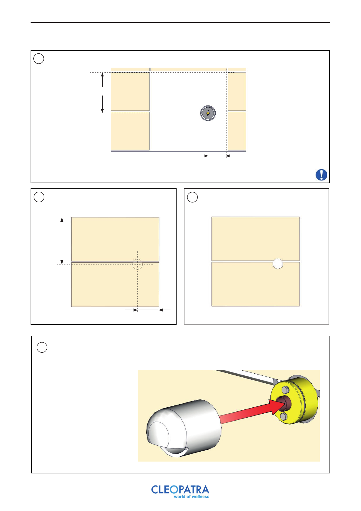
15.2 Placing steam outlet
1
Measure the distances to the center lines of the hole.
320 mm
137 m m
All distances serve as an example
Measure and mark these distances on the tile.
2
320 mm
137 mm
Place the steam cover on/over the steam outlet.
4
Cut a circle of Ø 64mm out of the tiles
3
and place the tiles on the wall.
22
Page 23
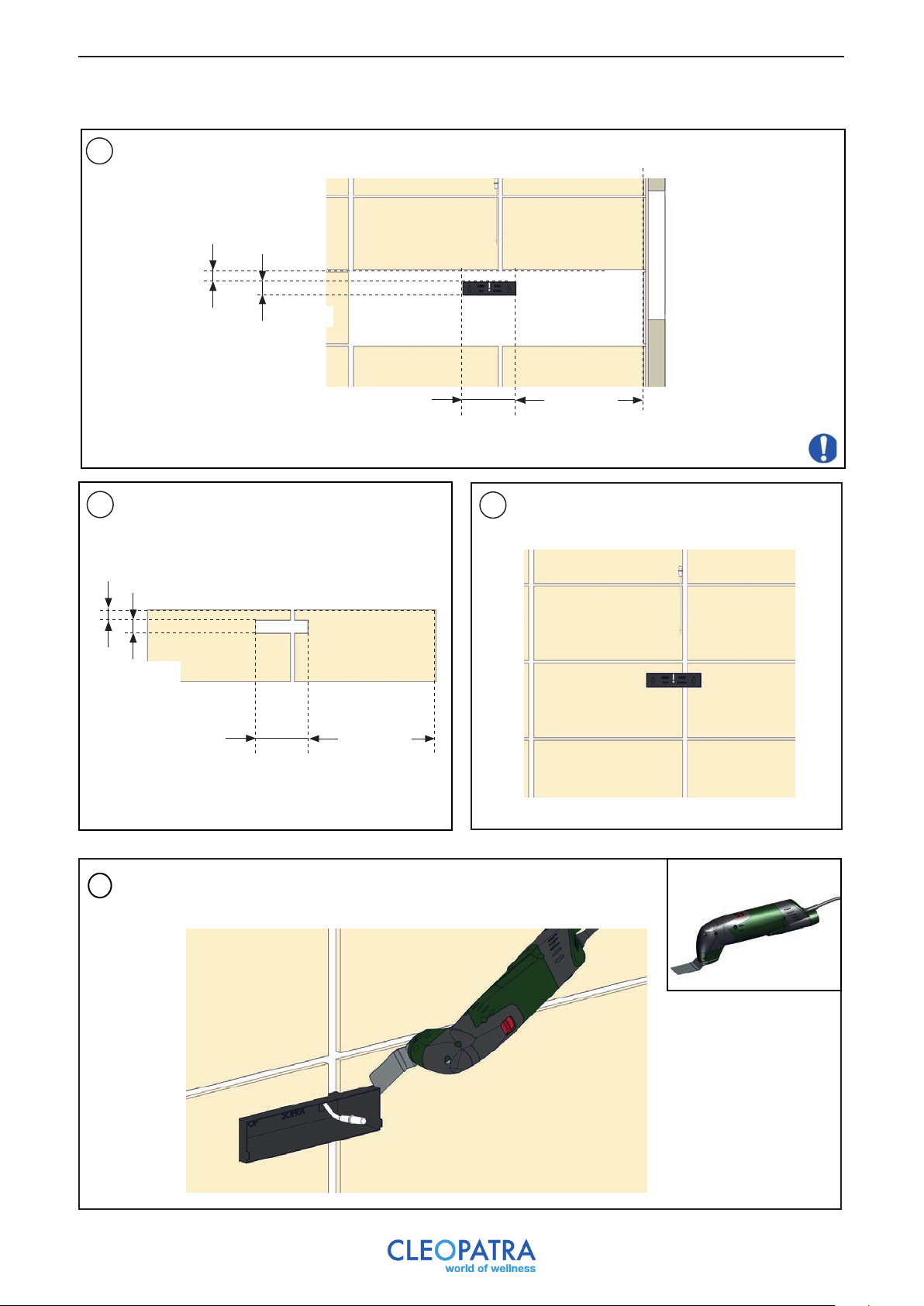
15.3 Installation of control
1
Measure the distances to the center lines of the hole.
42 mm
56 mm
Measure and mark these distances on the tile.
2
42 mm
56 mm
530 mm
220 mm
220 mm
530 mm
All distances serve as an example
Cut off the shape from the tiles and place the
3
tiles on the wall.
Saw the parts of the control that stick out. Use a multitool for this.
4
23
Page 24
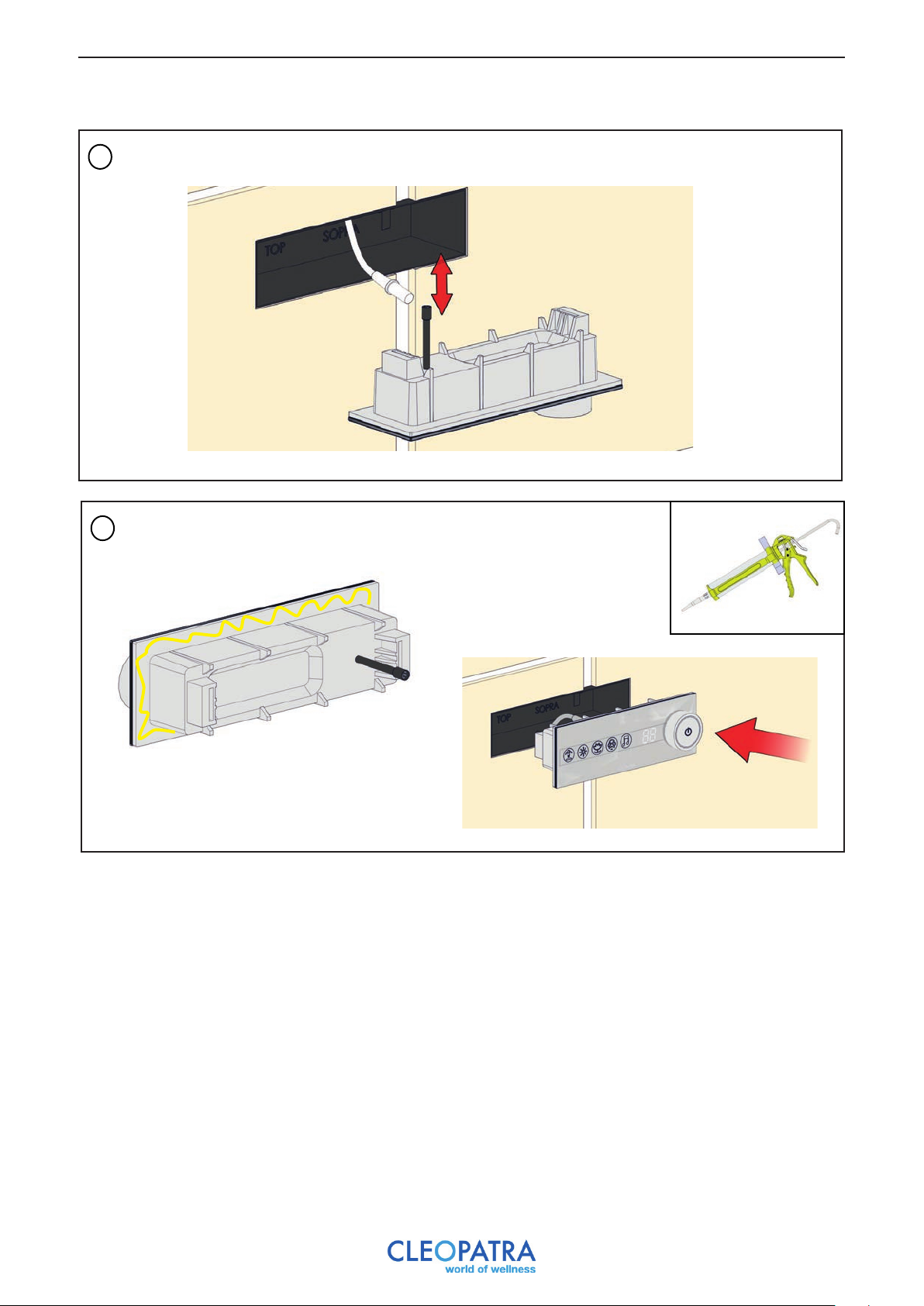
Connect the 2 cables together.
5
Kit the back of the controls and place it in the wall.
6
24
Page 25
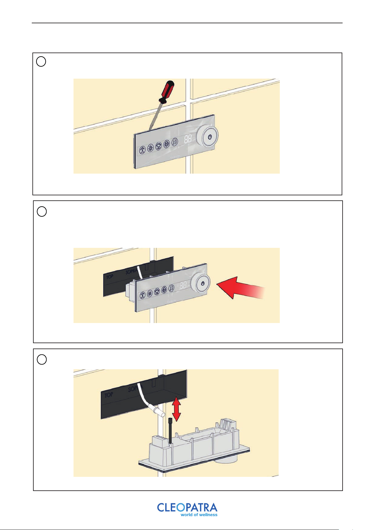
16 Removing the control
Gently pull the control with a flat screwdriver.
1
Pull out the control.
2
Disconnect the cables.
3
25
Page 26
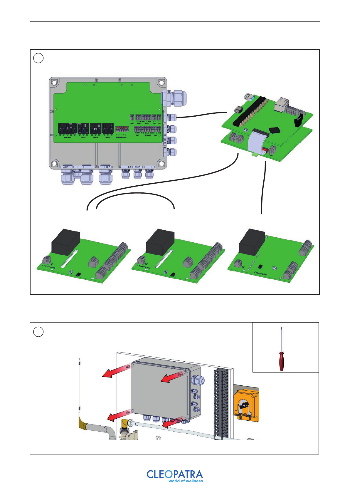
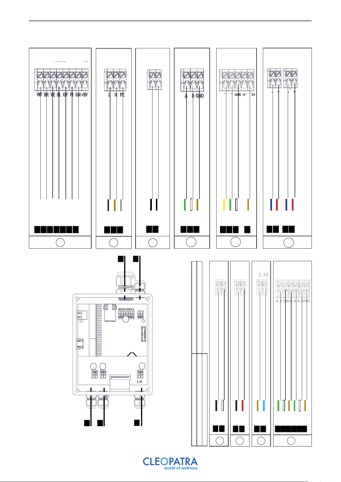
17 Overview of electrical connections
Route the control, temperature and safety sensor cables through the cable glands.
1
Electronics Brain
Cleopatra multimedia module
Control
Temperature sensor
Safety sensor
LED Spots module
(4 pieces)
17.1 Connecting electronics Brain
1
LED Spots module
(4 pieces)
LED rails module
26
Page 27
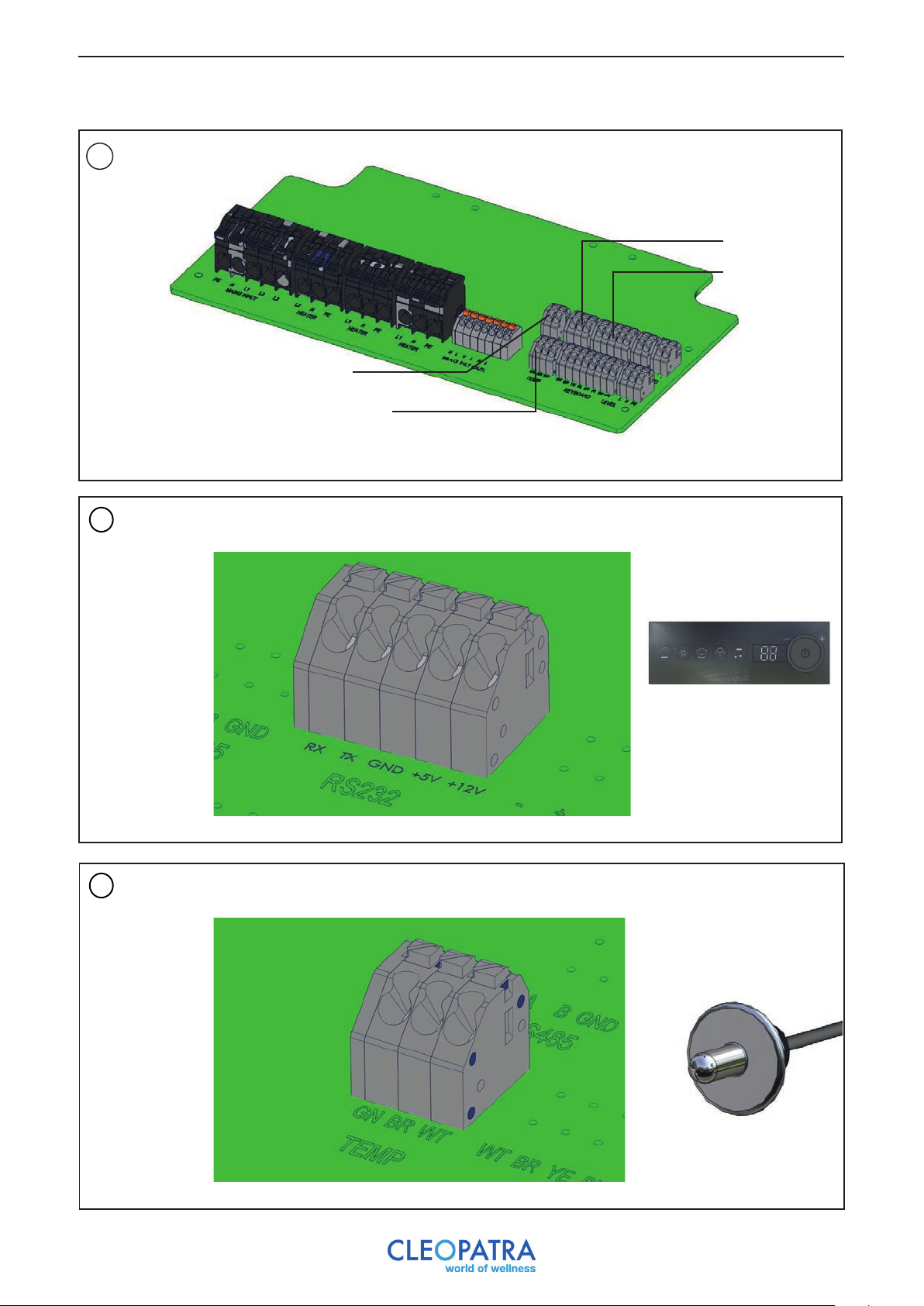
2
RS485
Control
Safety sensor
Temperature sensor
3
4
Yellow (RX) Green (TX) White(GND) B r ow n (+12V )
Steam Brain control
Green (GN) Brown (BR) White (WT)
Temperature sensor
27
Page 28
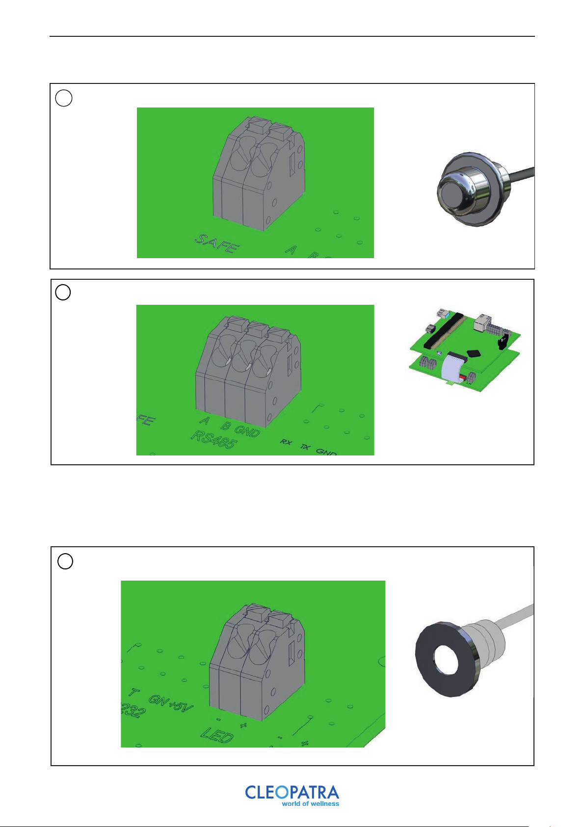
5
Black Black
Safety sensor
6
Green (A) White (B) Brown (GND)
Multimedia module
RS485
17.1. a Connecting electronics Brain - option white light
If you have only ordered the “white light” option, you can connect the lighting to this module. In this case you do
not need the Multimedia module.
1
Connect plus and minus according to LED specifications
White light 1
28
Page 29
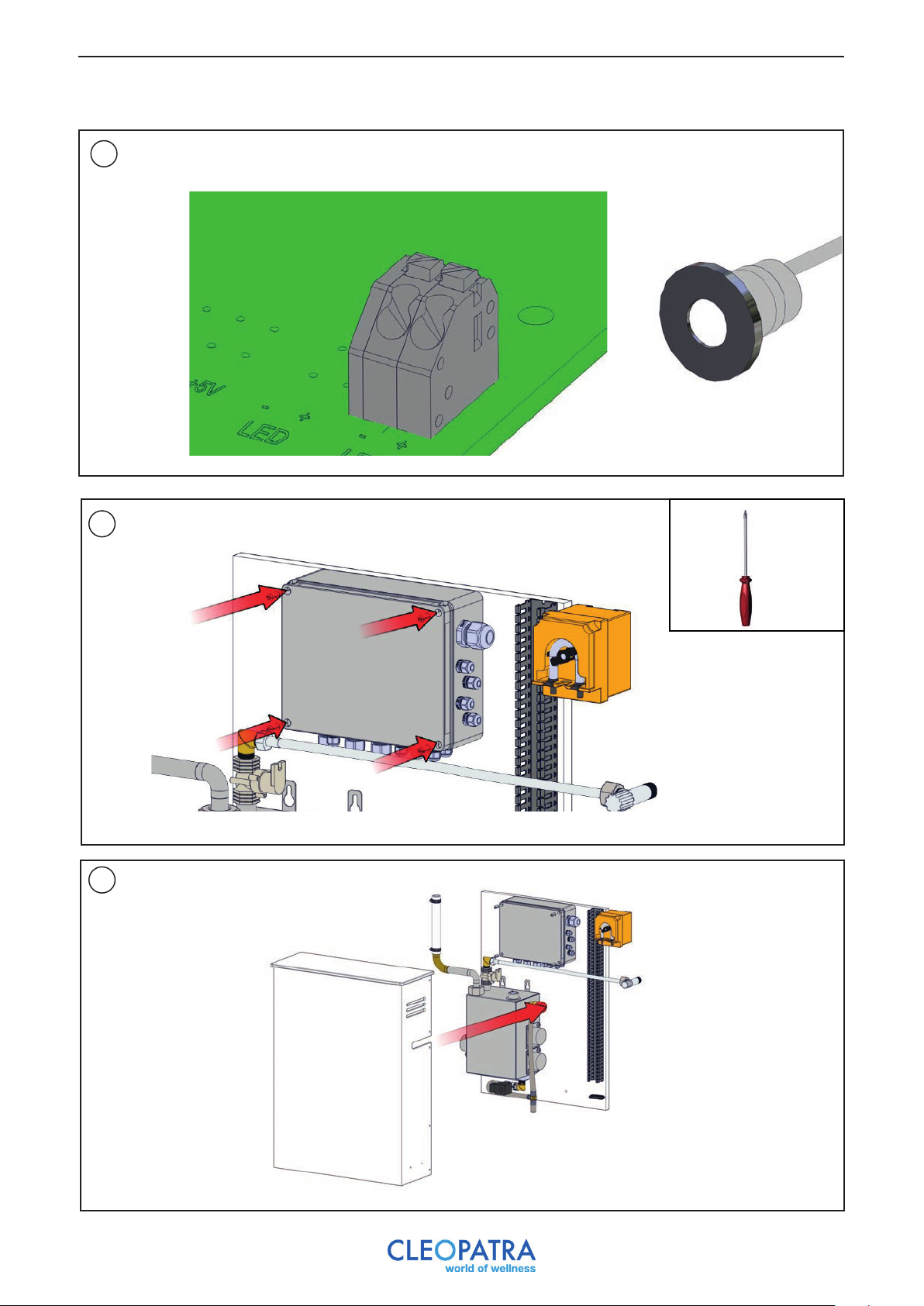
2
7
Connect plus and minus according to LED specifications
White light 2
8
29
Page 30
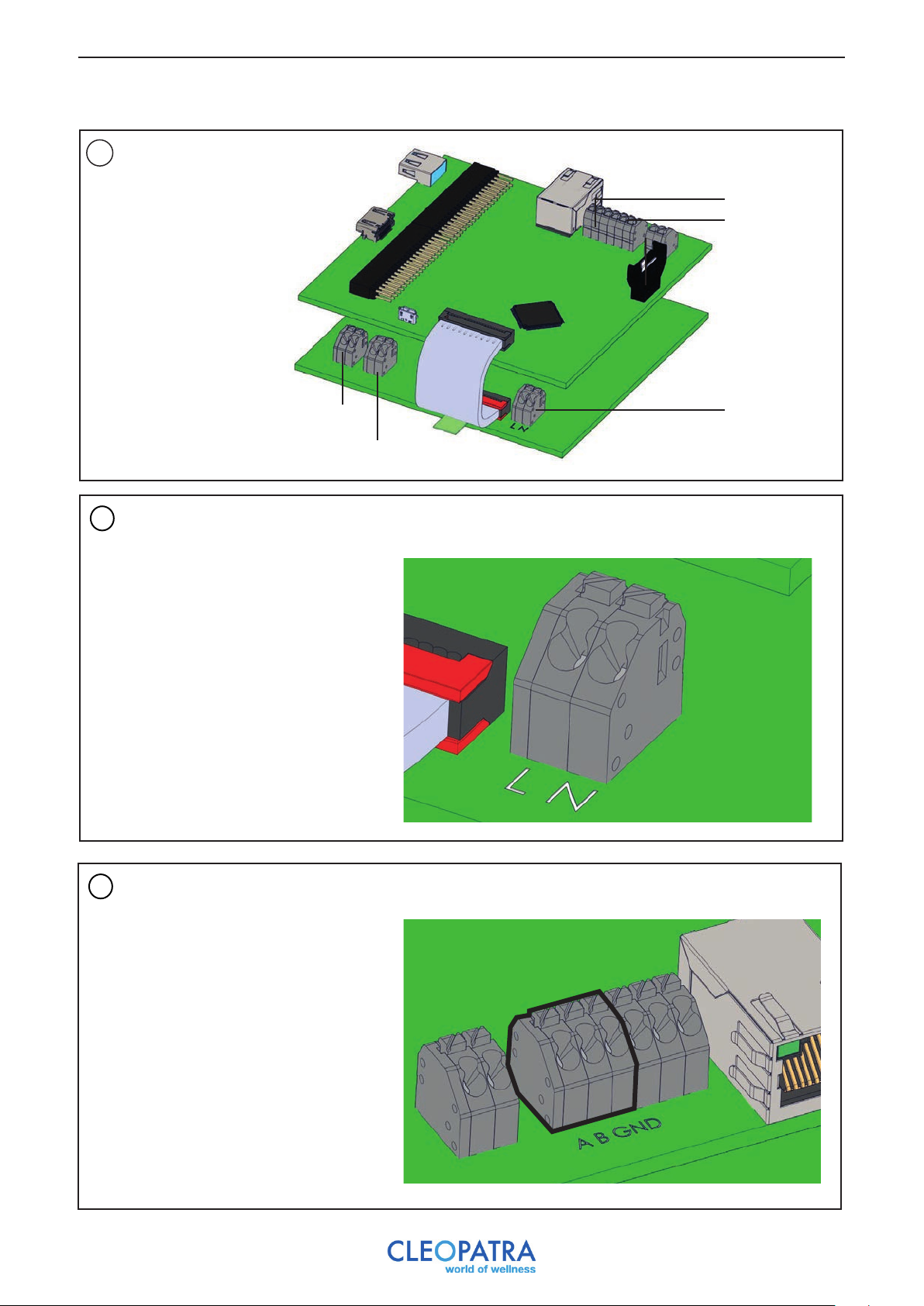
17. 2 Connecting Multimedia Module
Overview connections
1
Multimedia Module.
RS485 UIT
RS485 IN
2
Connection supply
Speaker 1
Speaker 2
Supply
Brown (L) Blue (N)
3
Green (A) White (B) Brown (GND)Connection RS485 IN
30
Page 31
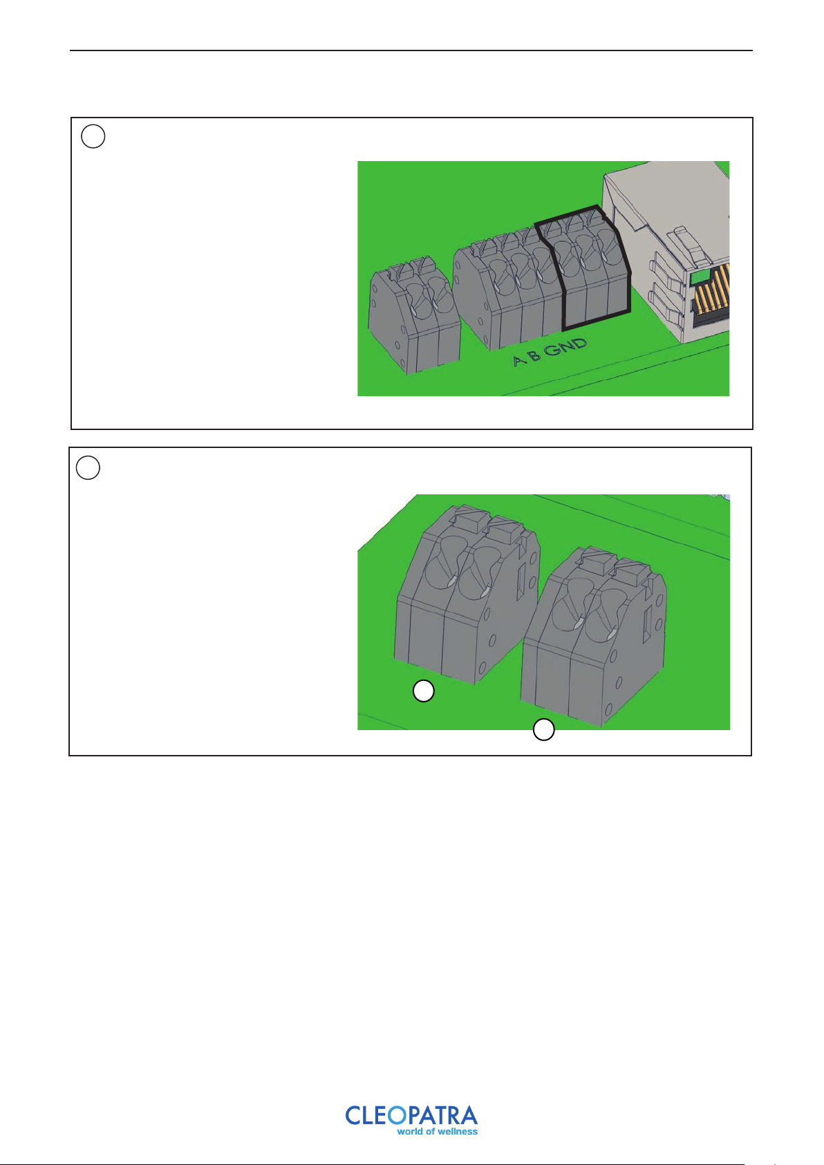
4
Bushing RS485 OUT on
other modules
Connection speaker 1 and/or 2.
5
Green (A) White (B) Brown (GND)
1) Black Grey 2) Black Red
1
2
31
Page 32
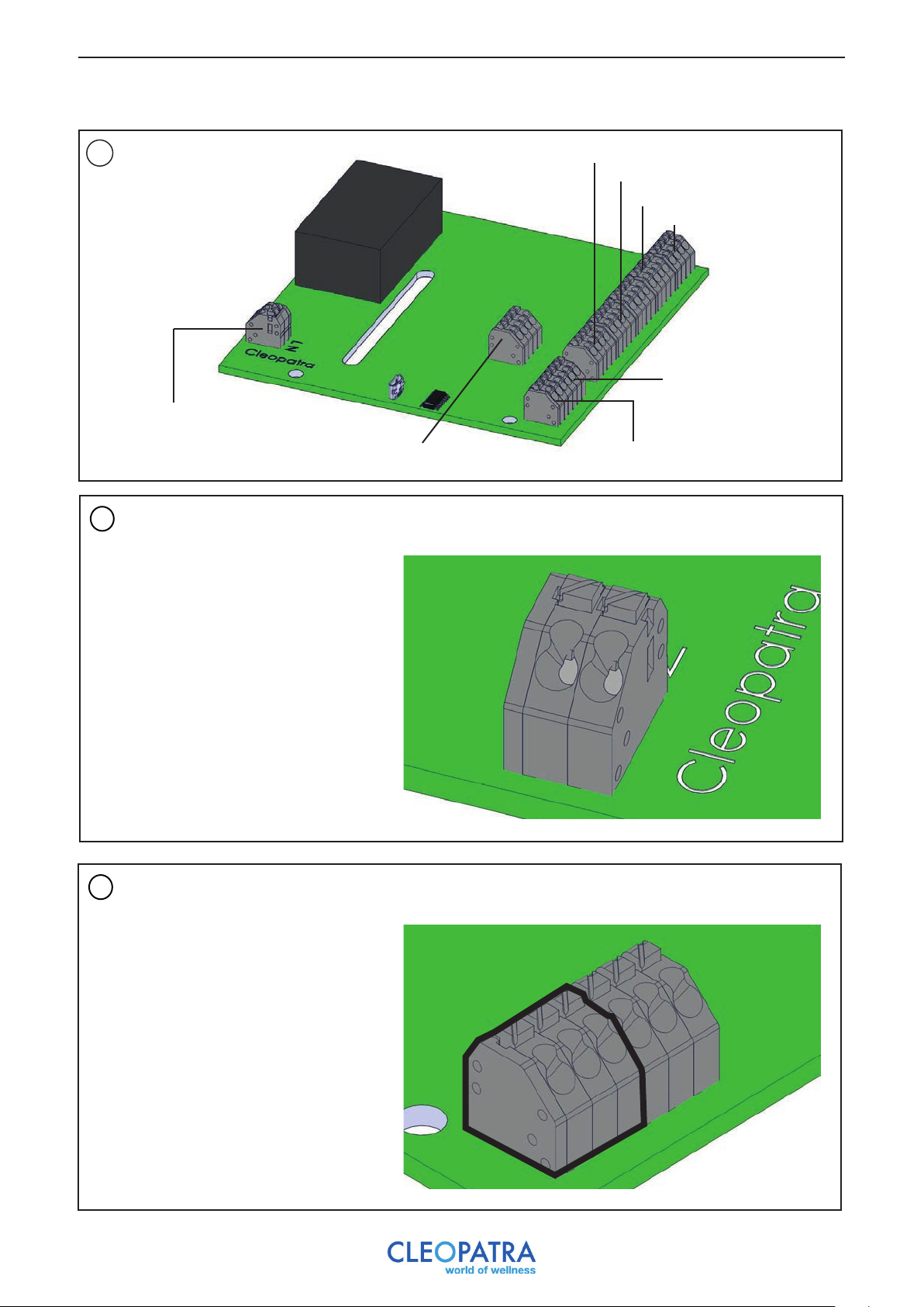
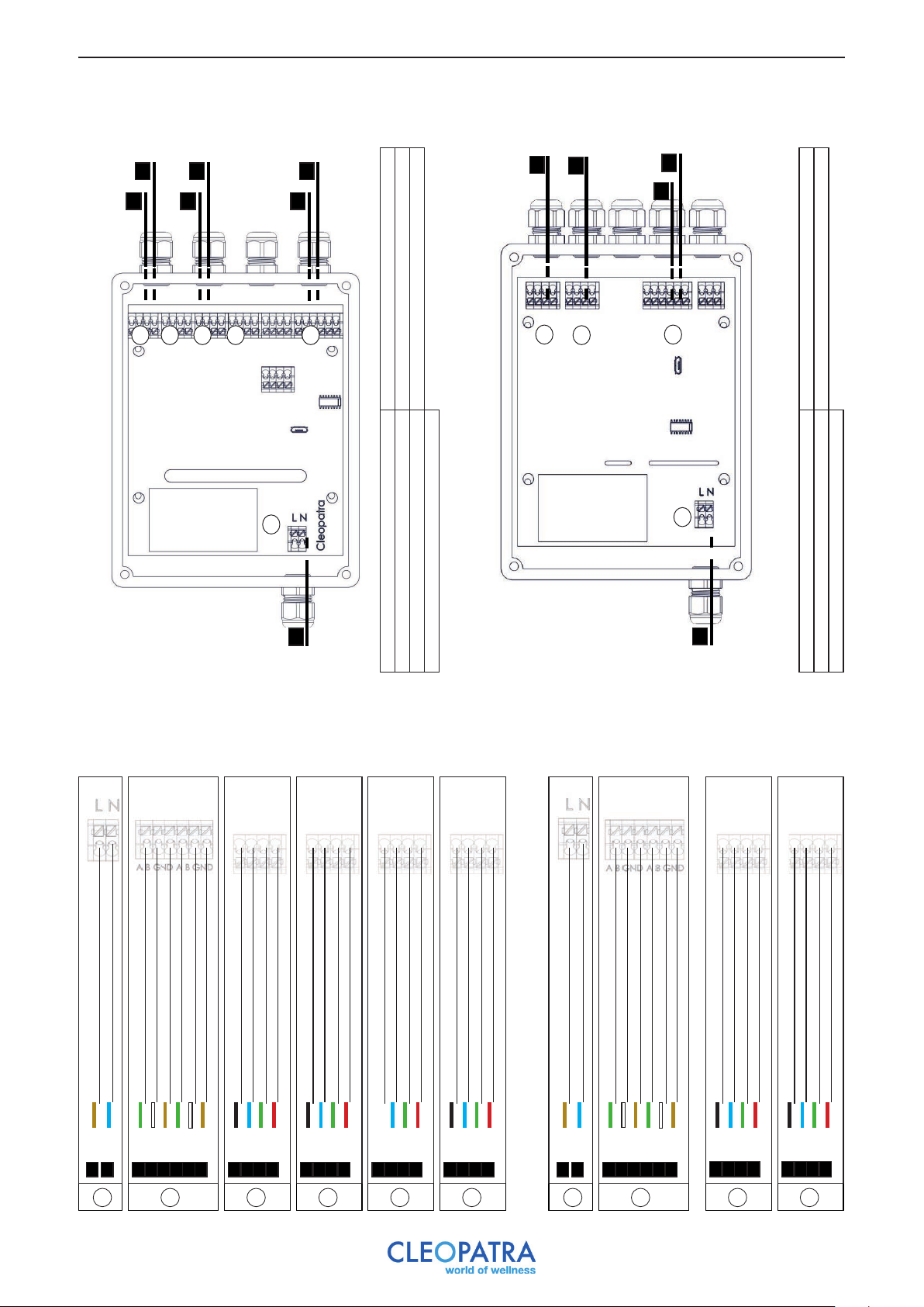
17. 3 Connection LED spots module
Overview connections
1
LED spots module.
Supply
2
Connection supply
LED spot 1
LED spot 2
LED spot 3
LED spot 4
RS485 OUT
External push-button RS485 IN
Brown (L) Blue (N)
Connection RS485 IN
3
Green (A) White (B) Brown (GND)
32
Page 33
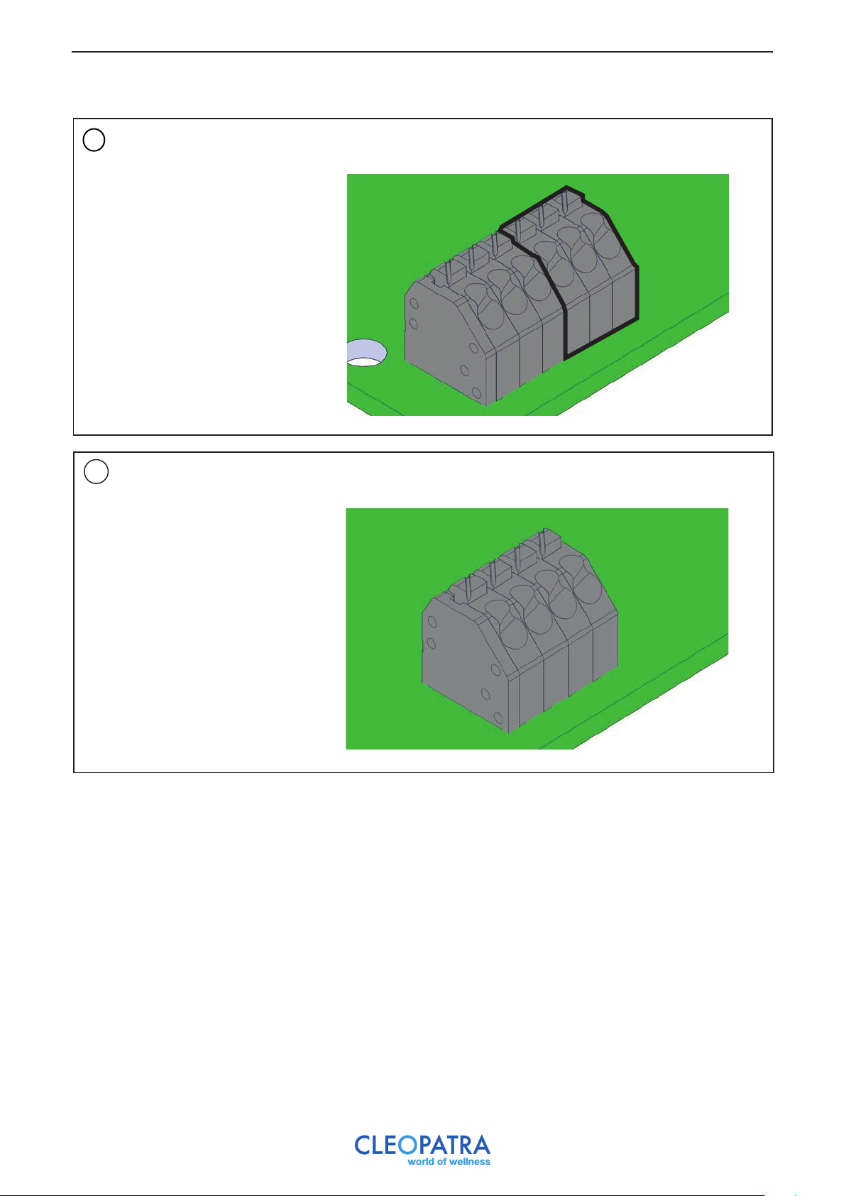
4
Bushing RS485 OUT on
other modules
5
Connection LED spot 1, 2, 3
and/or 4.
Green (A) White (B) Brown (GND)
1) Red 2) Green 3) Blue 4) Black
33
Page 34
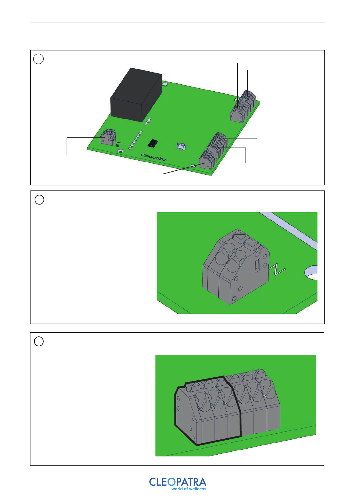
17. 4 Connection LED rails module
Overview connections
1
LED rails module.
Supply
2
Connection supply
LED rails 1 (max. 5m)
LED rails 2 (max. 5m)
RS485 OUT
RS485 IN
External push-button
Brown (L) Blue (N)
Connection RS485 IN
3
Green (A) White(B) Brown (GND)
34
Page 35
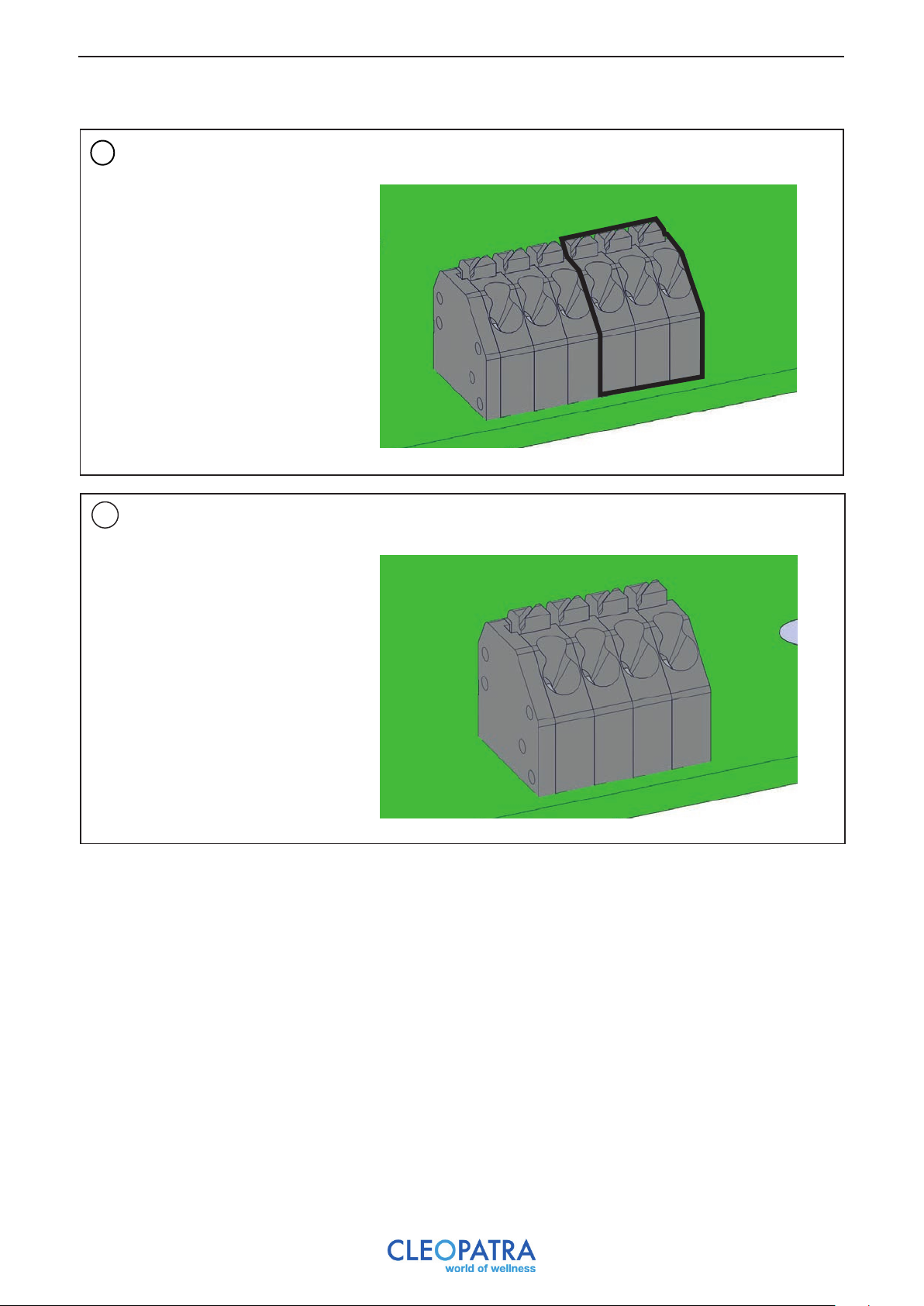
4
Bushing RS485 OUT on
other modules
5
Connection LED rails 1 and/or 2.
Green (A) White (B) Brown (GND)
1) Red 2) Green 3) Blue 4) Black
35
Page 36
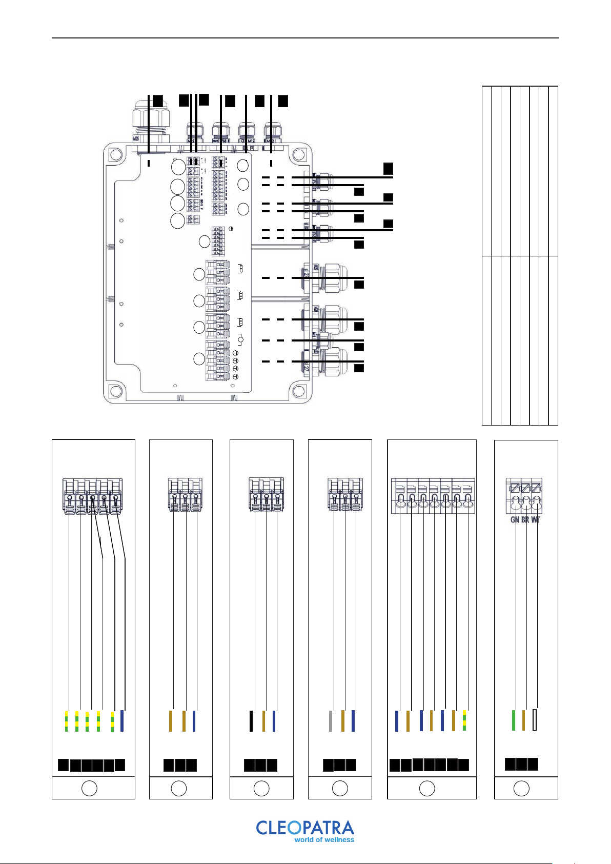
18 Electrical connections
16
C12
C9 C10 C11
15
14
RS485 RS232
save
12
11
13
level
LED LED
C8
C7
keyboard
temp
C6
6 8 10
Connection Brain
C1 C2 C3 C4
C5
inlt outl
LN LN LN
frag
L3 L N
L2 L N
L N
~
N L1
9: Fragrance pump, 2x 0.75, 230 VAC
10: LED 2, 2 x 0.75, 11.8 V VDC
12: Safety sensor, 2 x 0.75
11: LED 1, 2 x 0.75, 11.8 V VDC
13: Temperature sensor, 3 x 0.5, 5 VDC
14: Control Brain, 7 x 0.25, 5 VDC
15: Comm. RS485 , 2 x 0.25
16: Supply, 3/5 x 2.5, 230/400 VAC
1 2 3 4 5 7 9
1: Heating element 2, 3x 2.5, 230 VAC
2: Earth, 1 x 2.5
3: Heating element 3, 3x 2.5, 230 VAC
4: Heating element 1, 3x 2.5, 230 VAC
5: Water inlet valve, 2x0.75, 230 VAC
8: Comm.
6: Drain 9kW, 3x 0.75, 220 V
7: Water level sensor, 3x 0.75, 11.8 VAC
Earth Heating element 1
Earth
Gr/Ye
2
Earth Heating element 3
Earth Heating element 2
Gr/Ye
Gr/Ye
1
4
C1
N Heating element 1
N Heating element 2
L Heating element 2
N Mains
Earth Mains
Blauw
Gr/Ye
Gr/Ye
3
16
16
L1 Mains
Blue
Brown
Brown
1
1
16
C2
L Heating element 3
L2 Mains
Black
Brown
3
16
C3
N Heating element 3
Blue
3
L3 Mains
Grey
16
L Heating element 1
Bliue
Brown
4
4
C4
N Fragrance pump
Blue
9
N Water inlet valve
L Fragrance pump
Blue
Brown
556
9
L Water inlet valve
Brown
C5
N Drain
Blue
L Drain
Earth Drain
Brown
Gr/Ye
6
6
Temperature sensor (client)
Temperature sensor (client)
Temperature sensor (client)
Brown
Geen
White
131313
C6
36
Page 37
- 12 VDC LED (client)
Control One
Control One
Control One
Control One
Control One
Control One
Control One
Water level sensor
Water level sensor
Water level sensor
Black7Brown7Grey
7
C7
floor
story
nd
nd
C8
15
15
M4
M4
23
23
Safety sensor (cleint)
Safety sensor (client)
Black
Black
12
12
C9
RS 485 (client)
RS 485 (client)
RS 485 (client)
Green
White
151515
C10
Brown
RS 232 - Control Brain (client)
RS 232 - Control Brain (client)
Yellow
Green
141414
RS 232 - Control Brain (client)
White
C11
RS 232 - Control Brain (client)
Brown
14
- 12 VDC LED (client)
Blue
101011
+ 12 VDC LED (client)
Red
Blue
C12
+ 12 VDC LED (cleint)
Red
11
15: Comm. RS485, 2 x 0.25
floor 2
story 2
st
st
1
1
20
20
Connection Multimedia module
M1
M1
M2
M2
21
21
22
22
M3
M3
Speaker 1 (client)
Speaker 1 (client)
White
Black
20
20
20: Speaker 1, 2 x 0.25
21: Speaker 2, 2 x 0.25 23: Comm. RS485, 2 x 0.25
M1
22: Supply, 2x 0.25, 230 V
Speaker 2 (client)
Black
21
M2
Speaker 2 (client)
Red
21
N 230VAC Supply
L 230 VAC Supply
Blue
Brown
23
M3
23
RS458 (client)
RS458 (client)
White
Green
15
15
RS458 (client)
RS458 (cleint)
Green
Brown
24
15
M4
RS458 (client)
RS458 (client)
Brown
White
24
24
37
Page 38
35
34
33
32
31
23
43
42
31
41
S4
S5
S6
Connection LED spot module
S3
S2
33: LED 2, 2 x 0.75, 11.8 V VDC
34: LED 3, 2 x 0.75, 11.8 V VDC
35: LED 4, 2 x 0.75, 11.8 V VDC
33: LED 2, 2 x 0.75, 11.8 V VDC
34: LED 3, 2 x 0.75, 11.8 V VDC
35: LED 4, 2 x 0.75, 11.8 V VDC
R4
R3
S1
R2
42: LED Rail 1, 4 x 0.25, 11.8 V VDC
43: LED Rail 2, 4 x 0.25, 11.8 V VDC
42: LED Rail 1, 4 x 0.25, 11.8 V VDC
43: LED Rail 2, 4 x 0.25, 11.8 V VDC
R1
Aansluiting LED Rails module
30
30: Supply, 2 x 0.25
23: Comm. RS485, 2 x 0.25
31: Comm. RS485, 2 x 0.25
32: LED 1, 2 x 0.75, 11.8 V VDC
30: Voeding, 2 x 0.25
23: Comm. RS485, 2 x 0.25
31: Comm. RS485, 2 x 0.25
32: LED 1, 2 x 0.75, 11.8 V VDC
40
40: Supply, 2 x 0.25
31: Comm. RS485, 2 x 0.25
41: Comm. RS485, 2 x 0.25
40: Voeding, 2 x 0.25
31: Comm. RS485, 2 x 0.25
41: Comm. RS485, 2 x 0.25
N 230VAC Supply
L 230 VAC Supply
Blue
Brown
30
30
S1
RS458 (client)
RS458 (client)
White
Green
24
24
RS458 (client)
RS458 (client)
Green
Brown
31
24
S2
RS458 (client)
RS458 (client)
Brown
White
31
31
LED Spot 1 (client)
Blue
Black
32
LED Spot 1 (client)
32
LED Spot 1 (client)
Green
32
S3
LED Spot 1 (client)
Red
32
LED Spot 2 (client)
Blue
Black
33
LED Spot 2 (client)
33
LED Spot 2 (client)
Green
33
S4
LED Spot 2 (client)
Red
33
LED Spot 3 (client)
Blue
Black
34
LED Spot 3 (client)
34
LED Spot 3 (client)
Green
34
S5
LED Spot 3 (client)
Red
34
LED Spot 4 (client)
Blue
Black
35
LED Spot 4 (client)
35
LED Spot 4 (client)
Green
35
S6
LED Spot 4 (client)
Red
35
N 230VAC Supply
L 230 VAC Supply
Blue
Brown
40
40
R1
RS458 (client)
RS458 (client)
White
Green
31
31
RS458 (client)
RS458 (client)
Green
Brown
41
31
R2
RS458 (client)
RS458 (client)
Brown
White
41
41
LED Rails 1 (client)
Blue
Black
42
LED Rails 1 (client)
42
LED Rails 1 (client)
Green
42
R3
LED Rails 1 (client)
Red
42
LED Rails 2 (client)
Blue
Black
43
LED Rails 2 (client)
43
LED Rails 2 (client)
Green
43
R4
LED Rails 2 (client)
Red
43
38
Page 39

19 Declaration of conformity
EC Declaration of Conformity in accordance with the
low voltage directives 2014/35/Eu
Cleopatra B.V.
Oostzijde 295
1508 EN Zaandam, Holland
hereby declares that the following described steam generator in our delivered design meets the
correct basic safety and health requirements of the EC directives on the basis of its design and type,
as put into circulation by us. In case of adjustment of the product, not agreed with us, this declaration
will lose its validity.
Product: Steam generator
Intended use: Personal hygiene
System of the certificate of conformity: 4
Models: Steam Brain 3 kW
Steam Brain 4.5 kW
Steam Brain 6 kW
Steam Brain 9 kW
Characteristics: 3 kW
230 V, 1N, AC, 50Hz, max. 3.3 kW
Max. 14.3A, IPx4 (inside)
IP20 (outside), Class 1, Max. 1,0 MPa (10 bar)
Max. 80 ˚C
4.5 kW
400 V, 3N, AC, 50Hz, max. 4.5 kW
Max. 11.5A, IPx4 (inside)
IP20 (outside), Class 1, Max. 1,0 MPa (10 bar)
Max. 80 ˚C
6 kW
400 V, 3N, AC, 50Hz, max. 6 kW
Max. 12.5A, IPx4 (inside)
IP20 (outside), Class 1, Max. 1,0 MPa (10 bar)
Max. 80 ˚C
9 kW
400 V, 3N, AC, 50Hz, max. 9 kW
Max. 12.5A, IPx4 (inside)
IP20 (outside), Class 1, Max. 1,0 MPa (10 bar)
Max. 80 ˚C
Applicable EC directives: (1) Low voltage directives 2014/35/EU
(2) EMV-Directives (EMC) 2014/30/EU
Applicable European standards: (1) DIN EN 60335-2-98-1-A2
(1) DIN EN 60335 -1: 2014
(2) DIN EN 61000-6-1
(2) DIN EN 61000-6-3
(2) DIN EN 62233:2008-11
(2) DIN EN 60335-1:2012-10 parts 19.11.4.1 - 19.11.4.7
Date signature: Zaandam, 1 February 2017
Signer’s title: Niels Nieuweboer
General Manager
39
Page 40

Identification lable of the product
We reserve the right and to adjust technical changes and printing-related color deviations.
01-2019
Cleopatra B.V. Oostzijde 295, 1508 EN Zaandam
T: +31-75-6478200, [email protected], www.cleopatra-wellness.com
90179999
 Loading...