

CLEOPATRA Cleo Premium Pro 522, Cleo Premium Pro 832, Cleo Premium Pro, Cleo Premium Pro 524, Cleo Premium Pro 822 Mounting Instructions
...
Cleo Premium Pro
rofessional steam generator
P
MOUNTING INSTRUCTIONS
90549003 EN


Contents
1 Introduction 4
1.1 To the very beginning 4
1.2 Notes on the mounting instructions 4
2 For your safety 6
3 Product Overview 8
3.1 Models overview 8
3.2 Identicationoftheunit 9
3.3 Steamgeneratorconstruction 10
3.4 Functionaldescription 11
3.5 Humidicationsystemoverview 13
3.6 Options 14
3.7 Accessories 14
3.7.1 Accessories overview 14
3.7.2 Accessorydetails 16
3.8 Standarddelivery 17
3.9 Storing/Transportation/Packaging 17
4 Notes for the planning engineer 18
4.1 Selecting the unit version 18
4.1.1 Determinationoftherequiredsteamcapacity 18
4.1.2 Selectingtheunit 19
4.2 Selectingtheoptionsanaccessories 19
5 Mounting and installation work 20
5.1 Importantnotesformountingandinstallationwork 20
5.2 Installationoverview 21
5.3 Mounting the unit 22
5.3.1 Notesonlocatingtheunit 22
5.3.2 Mountingthesteamgenerator 24
5.3.3 Inspectingtheinstalledunit 25
5.4 Steaminstallation 26
5.4.1 Overviewsteaminstallation 26
5.4.2 Positioning/mountingthesteamdistributor 27
5.4.3 Installingthesteamandcondensatehose 28
5.4.4 Commonsteamandcondensatelineerrors 32
5.4.5 Inspectingthesteaminstallation 33
5.5 Waterinstallation 34
5.5.1 Overviewwaterinstallation 34
5.5.2 Notesonwaterinstallation 35
5.5.3 Inspectingthewaterinstallation 36
5.6 Electricinstallation 37
5.6.1
5.6.2 Notesonelectricinstallation 38
5.6.3 Inspectingtheelectricalinstallation 45
6 Productspecications 46
6.1 Technicaldata 46
6.2 Unit dimensions 47
WiringdiagramCleo Premium Pro
37
3

1 Introduction
1.1 To the very beginning
We thank you for having purchased the steam generator Cleo Premium
Pro.
The steam generator Cleo Premium Pro incorporates the latest technical
ad-van ces and meets all recognized safety standards. Nevertheless,
improper use of the Cleo Premium Pro may result in danger to the user or
third parties and/or impairment of material assets.
To ensure a safe, proper, and economical operation of the steam
generator Cleo Premium Pro, please observe and comply with all
information and safety instructions contained in the present mounting
instructions.
If you have questions, which are not or insufficiently answered in
this documentation, please contact Cleopatra B.V.
1.2 Notes on the mounting instructions
Limitation
The subject of these mounting instructions is the steam
generator Cleo Premium Pro. The various accessories are only
described insofar as this is necessary for proper operation of the
equipment. Further information on accessories can be obtained in
the respective instructions.
These mounting instructions are restricted to the installation of the
steam generator Cleo Premium Pro and is meant for well trained
personnel being sufficiently qualified for their respective work.
These mounting instructions are supplemented by various separate items
of documentation (operating instructions, spare parts list, manuals for accessories, etc.). Where necessary, appropriate cross-references are made
to these publications in the present documentation.
4

Explanation of the symbols used in this manual
CAUTION!
The catchword “CAUTION” designates notes in this documentation that,
if neglected, may cause damage and/or malfunction of the unit or other
material assets.
WARNING!
The catchword “WARNING” used in conjunction with the general caution
symbol designates safety and danger notes in this documentation that,
if neglected, may cause to injury to persons.
DANGER!
The catchword “DANGER” used in conjunction with the general caution
symbol designates safety and danger notes in this documentation that,
if neglected, may lead to severe injury or even death of persons.
Safekeeping
Please safeguard these mounting instructions in a safe place, where it can
be immediately accessed. If the equipment changes hands, the documentation should be passed on to the new operator.
If the documentation gets mislaid, please contact Cleopatra B.V.
Language versions
The present mounting instructions are available in various languages. Please
contact Cleopatra B.V.
Copyright protection
The present mounting instructions are protected under the Copyright
Act. Passing-on and reproduction of the manual (or part thereof) as well
as ex-ploitation and communication of the contents are prohibited without
written permission by the manufacturer. Violation of copyright terms is
subject to legal prosecution and arises liability for indemnification.
The manufacturer reserves the right to fully exploit commercial patent
rights.
5

2 For your safety
General
Every person working with the Cleo Premium Pro must have read and
un-derstood the present mounting instructions before carrying out any
instal-lation work.
Knowing and understanding the contents of the mounting instructions is
a basic requirement for protecting the personnel against any kind of
danger, to prevent faulty installation, and to install and operate the unit
safely and correctly.
All ideograms, signs and markings applied to the unit must be
observed and kept in readable state.
Qualification of personnel
All actions described in the present mounting instructions must be
carried out only by well trained and sufficiently qualified personnel
authorised by the owner.
For safety and warranty reasons any action beyond the scope of
this manuals must be carried out only by qualified personnel authorised
by the manufacturer.
It is assumed that all persons working with the Cleo Premium Pro are
familiar and comply with the appropriate regulations on work safety
and the prevention of accidents.
Intended use
The steam generator Cleo Premium Pro is intended exclusively for generation of steam for a steam bath within the specified operating condi-tions
(see chapter 6 “Product specifications”). Any other type of application
without the express written consent of the manufacturer is considered
as not conforming with the intended purpose and may lead to the Cleo
Premium Pro becoming dangerous.
Operation of the equipment in the intended manner requires that all the
information in these instructions is observed (in particular the safety
instructions).
Danger that may arise from the unit:
DANGER!
Danger of electric hazard!
The Cleo Premium Pro is mains powered. One may get in touch
with live parts when the unit is open. Touching live parts may
cause se-vere injury or danger to life.
Prevention: The Cleo Premium Pro must be connected to the mains
only after all mounting and installation work has been completed, all
installa-tions have been checked for correct workmanship and the
covers has been relocated properly.
6

Behaviour in case of danger
All persons working with the Cleo Premium Pro are obliged to
report any alterations to the unit that may affect safety to the
owner without delay and to secure such a unit against accidental power-
up.
Prohibited modifications to the unit
No modifications must be undertaken on the Cleo Premium Pro without
the express written consent of the manufacturer.
For the replacement of defective components use exclusively original ac-
cessories and spare parts available from Cleopatra B.V.
7
3 Product Overview
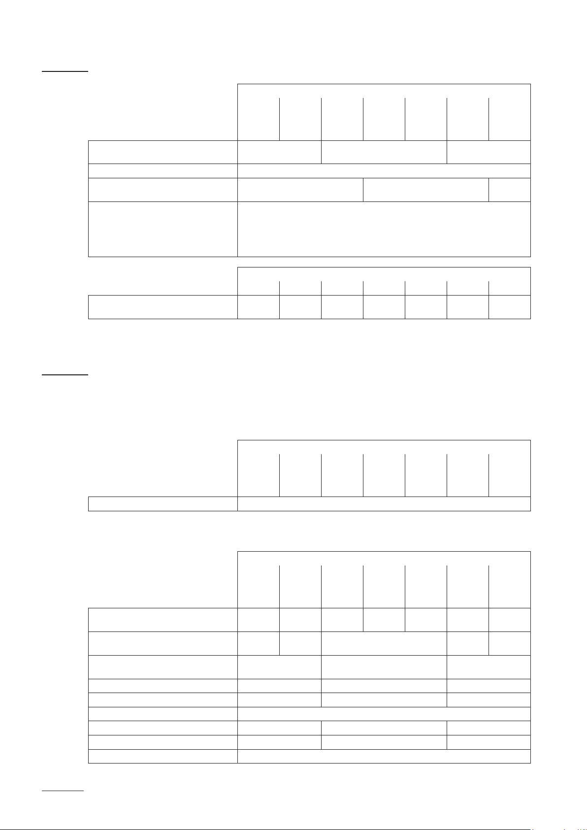
3.1 Models overview
Steam generators Cleo Premium Pro are available with different
heating voltages and steam capacities ranging from 5 kg/h up to a
maximum of 65 kg/h.
Heating voltage ** Max. steam capacity
in kg/h
5 534 x
8 834 x
400V3
(400 V/3~/50...60 Hz)
400V2
(400 V/2~/50...60 Hz)
230V3
(230 V/3~/50...60 Hz)
230V1
(230 V/1~/50...60 Hz)
** Other heating voltages on request
15 1534 x
23 2364 x
32 3264 x
45 4564 x
65 6564 x
5 524 x
8 824 x
5 532 x
8 832 x
15 1532 x
23 2362 x
32 3262 x
5 522 x
8 822 x
Model Cleo
Premium Pro
Unit size
small medium large
Key model designation
Product designation:
Unit model:
Heating voltage:
400V/3~/50...60Hz: 400V3
400V/2~/50...60Hz: 400V2
230V/3~/50...60Hz: 230V3
230V/1~/50...60Hz: 230V1
Example:
Cleo Premium Pro
4564 400V3
8
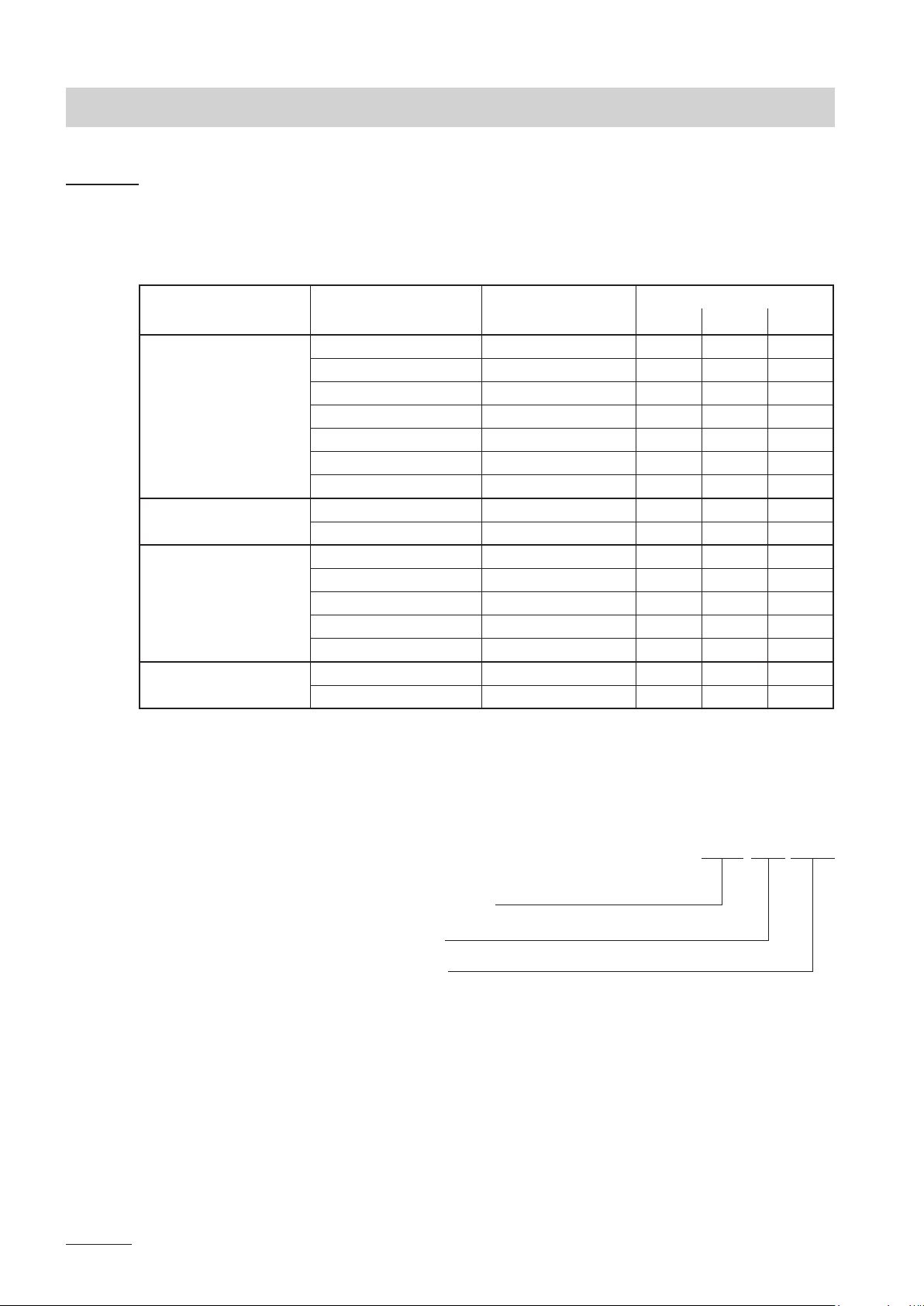
3.2 Identicationoftheunit
The identication of the unit is found on the type plate:
Type designation Serial number (7 digits) Month/Year
Heating voltage
Maximum steam capacity per unit
Admissible water supply pressure
Field with certication symbols
Power consumption
Control voltage
Type: Premium Pro 4564 Ser.Nr.: XXXXXXX 02.10
Heating voltage: 400V / 3~ / 50...60Hz Power: 33.8 kW
Steam capacity: 45.0 kg/h Ctrl. Voltage: 230V / 1~ / 50...60Hz
Water pressure: 1...10 bar
9
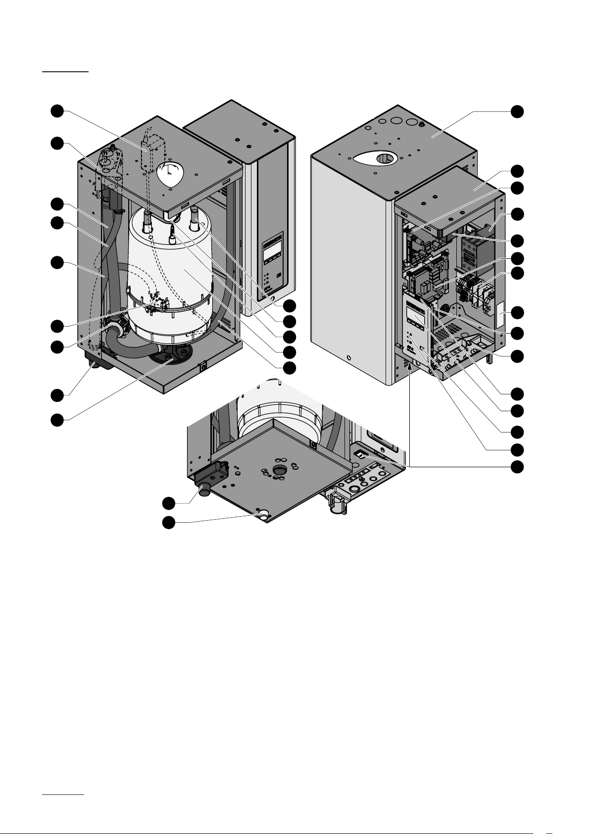
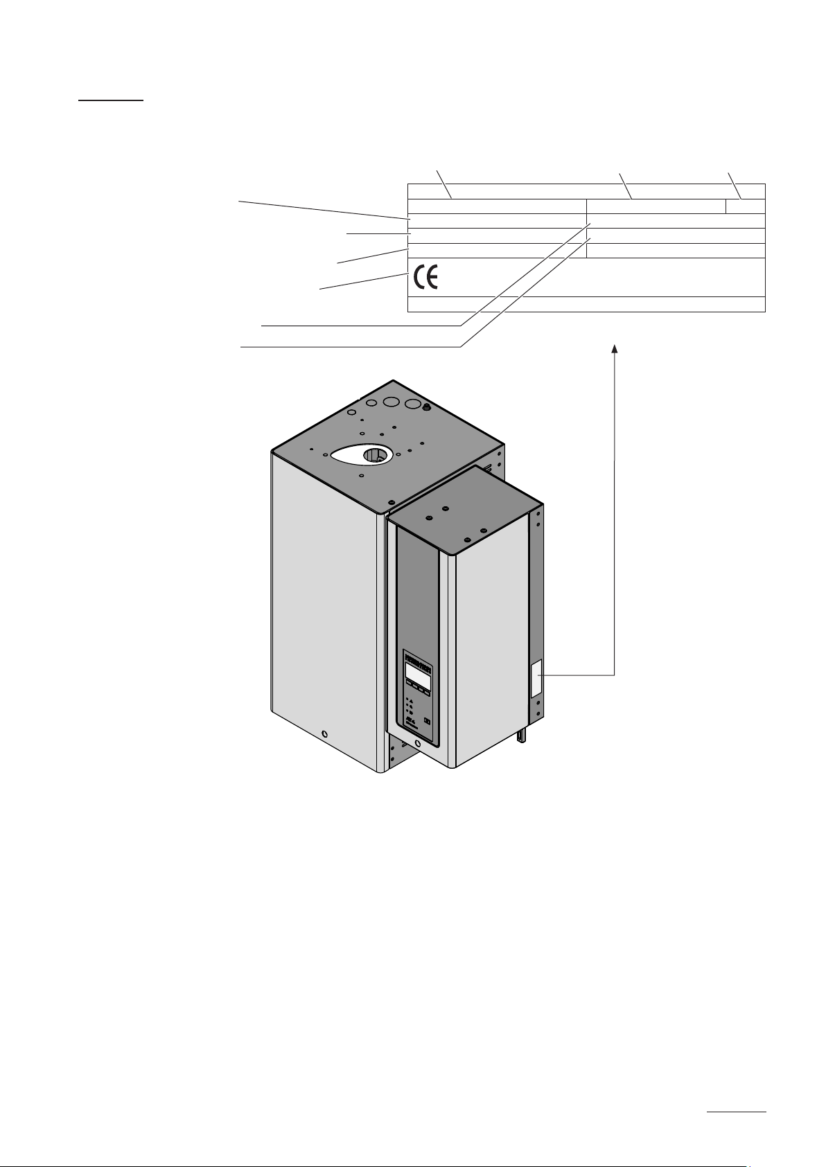
3.3 Steam generator construction
16
17
18
19
20
21
22
23
24
29
28
27
26
25
1
2
3
4
5
6
7
8
9
10
11
12
13
30
31
gure shows medium unit
1 Steam cylinder compartment
2 Control compartment
3 Power board
4 Main contactor
5 Transformer
6 Steam bath board
7 Connecting terminals
8 Type plate
9 Remote operating and fault indication board (option)
10 Cable openings
11 Control board with CF Card
12 Display and control unit
13 Drain key
14 Operation status indicators
15 Unit switch
16 SC pump
14
15
17 Water cup
18 Filling and draining hose
19 Water supply hose
20 Overow hose
21 Inlet valve
22 Drain pump
23 Drain cup
24 Steam cylinder receptacle
25 Drain hose (manual drain)
26 Steam cylinder
27 Level sensor
28 Steam outlet
29 Electrode plug
30 Drain connector
31 Water supply connector
10
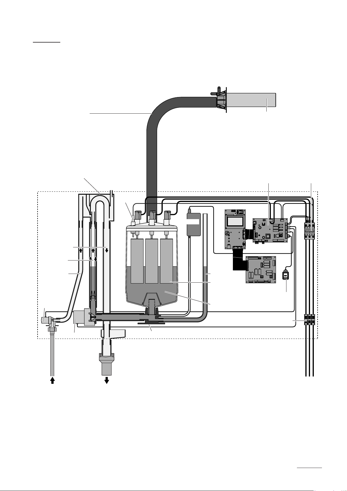
3.4 Functional description
The steam generator Cleo Premium Pro is a pressureless steam
generator that utilizes an electrode heating. The steam generator
Cleo Premium Pro is designed for steam generation for steam baths.
Steam hose
Water cup
Overow hose
Filling and
draining hose
Water supply
hose
Inlet valve
Level sensor
SC pump
Control board
Drain hose
Electrodes
Steam cylinder
Steam distributor
Current sensor
Power board
Steam bath board
Unit switch
Main contactor
Drain pump
Connecting terminals
Steam cylinder receptacle
Steam generation
Any time steam is requested, the electrodes are supplied with voltage via
main contactor. Simultaneously, the inlet valve opens and water enters the
steam cylinder from the bottom via water cup and supply line. As soon as the
electrodes come in contact with the water, current begins to ow between
the electrodes, eventually heating and evaporating the water. The more the
electrode surface is exposed to water, the higher is the current consumption
and thus the steam capacity.
11

Upon reaching the requested steam capacity, the inlet valve closes. If the
steam generation decreases below a certain percentage of the required
capacity, due to lowering of the water level (e.g. because of the evaporation process or drainage), the inlet valve opens until the required capacity
is available again.
If the required steam capacity is lower than the actual output, the inlet valve
is closed until the desired capacity is achieved by lowering of the water level
(evaporation process).
Level monitoring
A sensor provided in the steam cylinder cover detects when the water level
gets too high. The moment the sensor comes in contact with water, the
inlet valve closes.
Drainage
As a result of the evaporation process, the conductivity of the water increases
due to an escalating mineral concentration. Eventually, an inadmissibly high
current consumption would take place if this concentration process were
permitted to continue. To prevent this concentration from reaching a value,
unsuitably high for the operation, a certain amount of water is perio dically
drained from the cylinder and replaced by fresh water.
Lime management
The interval controlled SC pump blows air into the steam cylinder. Thus
keeping the solved minerals in the water in motion as a result they are
discharged with the automatic drain cycles.
Control steam production
The steam production is controlled steplessly (continuous control) by the
KTY temperature sensor and the integrated continuous controller.
Steam bath control
The control of the steam bath components (light, fans, fragrance pumps,
bench heating, etc.) is established via the integrated steam bath board.
12
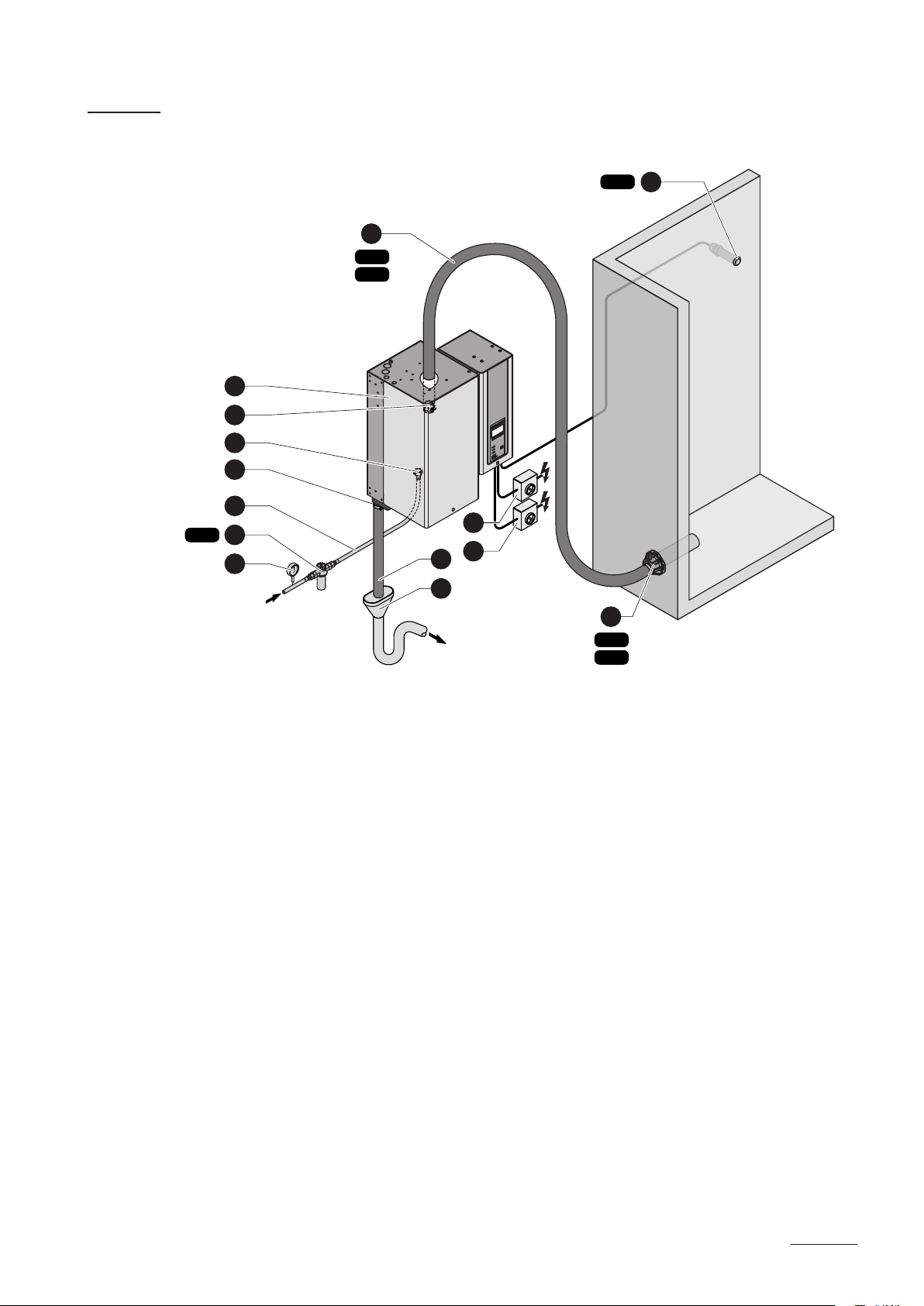
3.5 Humidicationsystemoverview
12
DS22
DS35
1
2
3
KTY
14
4
5
Z261
6
7
125...1250 µS/cm
1...10 bar
1...40 °C
1 Steam generator
2 Steam connector
3 Water drain connector
4 Water supply connector
5 Water connection hose G 3/4"- G 3/8"
(included in the delivery)
6 Filter valve (accessory “Z261”)
7 Manometer (installation recommended)
ONOFF
ONOFF
10
11
9
8
13
W22
W35
8 Funnel with siphon (building side)
9 Water drain hose (included in the delivery)
10 Service switch heating voltage supply (building side)
11 Service switch control voltage supply (building side)
12 Steam hose (accessory “DS22”/“DS35”)
13 Steam distributor (accessory “W..”/“DDS...”/“DDL...”)
14 Temperature sensor (accessory “KTY”)
13
3.6 Options
Steam hose connector with condensate trap
Cable glands CG
Internal control voltage supply
(for mains supply with neutral lead)
@-Link Cleo Premium Pro
Gateway to connect the Cleo Premium
Pro to a building management system.
Two versions are available: BACnet/IP
or LonWorks.
Steam cylinder for low water
conductivity from 80 to 125 µS/cm
Cleo Premium Pro...
522
524
532
534
534 834
1x
534A-L1x834A-L1x1534A-L1x2364A-L1x3264A-L1x4564A-L
822
824
832
834
1xCT22 1xCT35 2xCT35
1xS-CVI 1xM-CVI 1xL-CVI
Conguration according to separate documentation
1532
1534
Cleo Premium Pro... (400 V/3~/50...60
Hz) 1534 2364 3264
2362
2364
3262
3264
4564 6564
4564 6564
___
3.7 Accessories
3.7.1 Accessories overview
Accessories for water installation
Filter valve 1xZ261
Accessories for steam installation
Steam distributor (up to max. 4 kg/h)
(Details see chapter 3.7.2)
Steam distributor (4...32 kg/h)
(Details see chapter 3.7.2)
Steam distributor (4...65 kg/h)
(Details see chapter 3.7.2)
Steam hose / meter 1xDS22 1xDS35 2xDS35
EcoTherm Insulation hose / meter 1xECT22 1xECT60 2xECT60
Condensate hose / meter KS10
Condensate drain 1xCD22 1xCD35 2xCD35
T-piece fragrance injection 1xTSD22 1xTSD35 2xTSD35
Fragrance pump 1xFP 240V
Cleo Premium Pro...
522
524
532
534
522
524
532
534
1xDDS22 ___ ___ ___ ___ ___ ___
___ 1xDDL22 1xDDL35 ___ ___
822
824
832
834
822
824
832
834
1xW22 1xW35 2xW35
1532
1534
1532
1534
2362
2364
Cleo Premium Pro...
2362
2364
3262
3264
3262
3264
4564 6564
4564 6564
14
Accessories for operation control
Cleo Premium Pro...
522
524
532
534
Temperature sensor 1xKTY
Cleo Premium Pro Remote-Terminal 1 Terminal (RP) for the remote control of up to 8 steam generators
Cleo Premium Pro Touch Screen Panel 1xTSP
822
824
832
834
1532
1534
2362
2364
3262
3264
4564 6564
General accessories
Cleo Premium Pro...
522
524
532
534
All-weather protective housing
822
824
832
834
1532
1534
Layout according to the separate data sheet
2362
2364
3262
3264
4564 6564
15
3.7.2 Accessory details
3.7.2.1 3.7.2.1 Steam distributor DDS22
ø22.5 mm
ø48.5 mm
max. 19 mm
3.7.2.2 3.7.2.2 Steam distributor DDL22/DDL35
ø43 mm
max. 18 mm
3.7.2.3 3.8.2.3 Steam distributor W22/W35
DDL22: ø22.5 mm
DDL35: ø35 mm
W22: ø43 mm
W35: ø61 mm
16
W22: ø22.5 mm
W35: ø35 mm

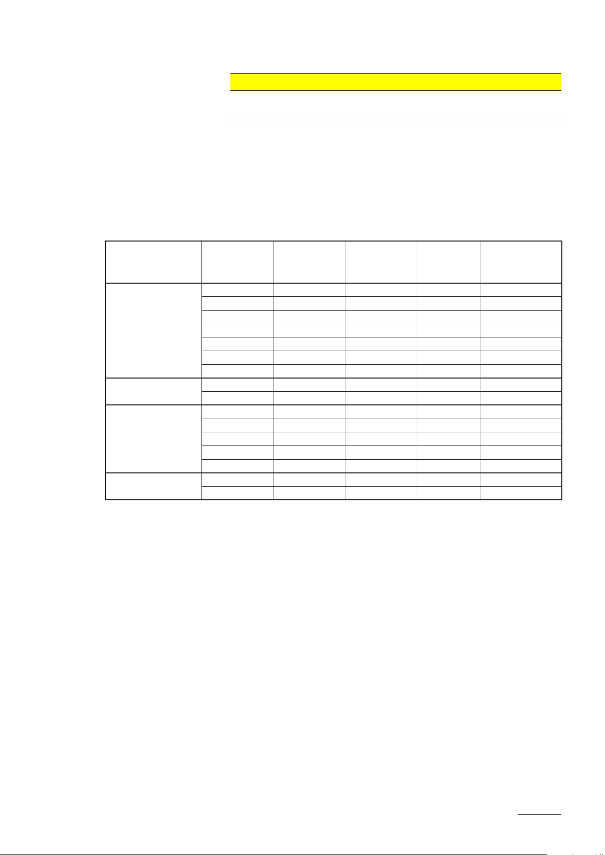
3.8 Standard delivery
The standard delivery includes:
– Steam generator Cleo Premium Pro with water connection hose G 3/4"
- G 3/8" and water drain hose ø 31/40 mm equipped with the options
ordered according to chapter 3.6, fixing set, mounting instructions (this
document) and operating instructions, packaged in cardboard box
Unit type Dimensions packaging (L x W x D) Transport weight
522, 524, 532, 534,
822, 824, 832, 834
1532, 1534,
2362, 2364
3262, 3264,
4564, 6564
– Ordered accessories with operating instructions according chapter 3.7,
packed separately
– Spare parts list
3.9 Storing/Transportation/Packaging
705 mm x 505 mm x 325 mm 14 kg
750 mm x 585 mm x 415 mm 21 kg
770 mm x 640 mm x 420 mm 31 kg
Storing
Store the unit in a protected area meeting the following requirements:
– Room temperature: 1 ... 40 °C
– Room humidity: 10 ... 75 %rh
Transportation
For optimum protection always transport the unit in the original packaging.
The weight of the units with a steam capacity of more than 8 kg/h is more
than 20 kg (see chapter 6.1 “Technical data”). Therefore, always transport
these units with the help of another person or use an appropriate lifting
device. Always place the unit on its back side.
Packaging
Keep the original packaging of the Cleo Premium Pro for later use.
In case you wish to dispose of the packaging, observe the local regulations
on waste disposal. Never dispose of the packaging to the environment.
17
4 Notes for the planning engineer
4.1 Selecting the unit version
To select the unit version the following planning steps are required:
1. Determinating the required maximum steam capacity according chapter 4.1.1
2. Selecting the unit version from the table in chapter 4.1.2
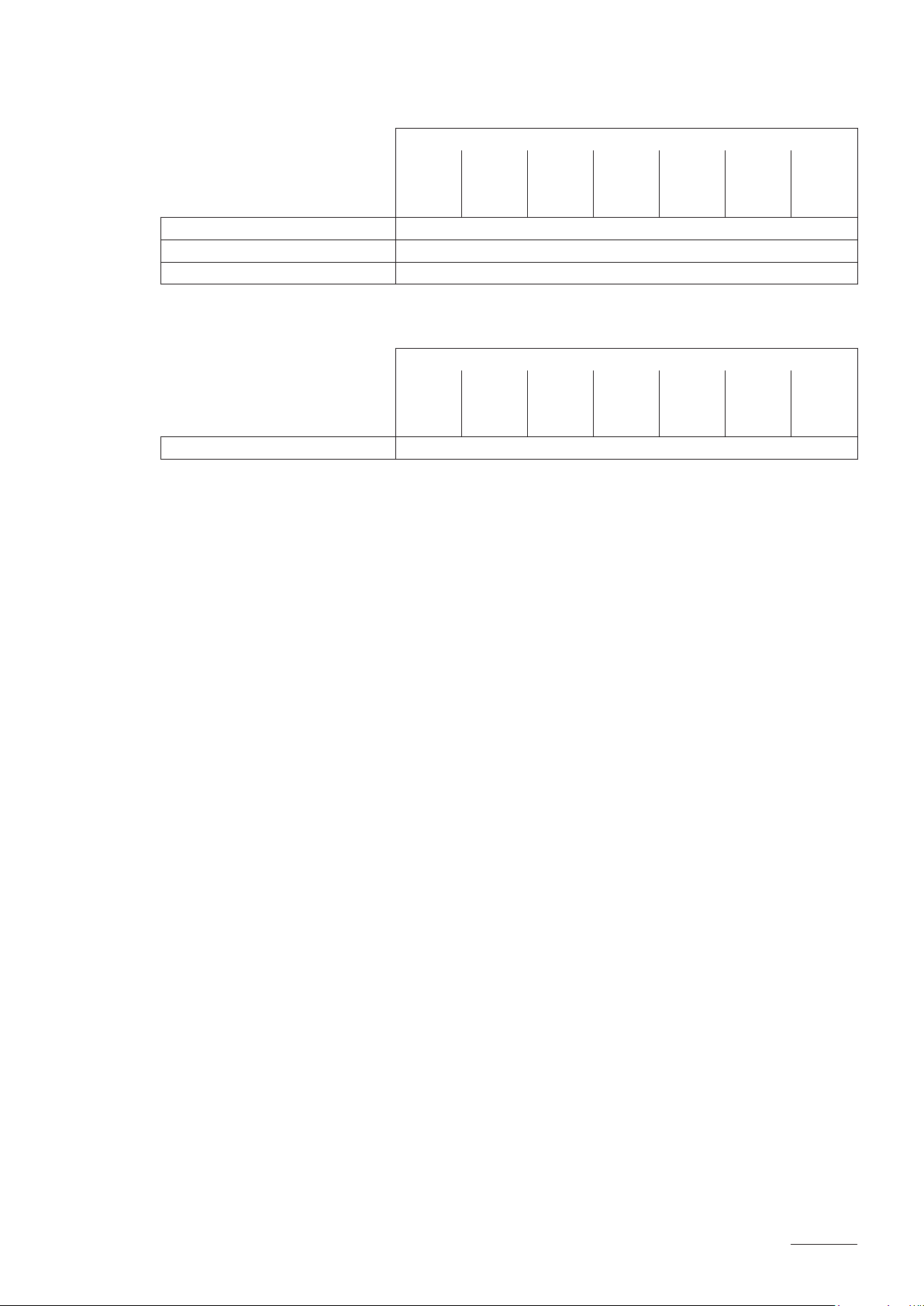
4.1.1 Determination of the required steam capacity
The steam capacity required for a particular steam bath can be determined
with the following table:
Cabin size Required steam capacity
Plastic cabin brick lined cabin
3
4 m
3
8 m
3
12 m
3
16 m
3
20 m
3
24 m
3
28 m
3
32 m
3
36 m
3
40 m
3
44 m
3
48 m
3
52 m
3
56 m
3
60 m
5 kg/h 8 kg/h
8 kg/h 12 kg/h
10 kg/h 15 kg/h
12 kg/h 18 kg/h
13 kg/h 21 kg/h
15 kg/h 24 kg/h
17 kg/h 26 kg/h
18 kg/h 29 kg/h
20 kg/h 31 kg/h
21 kg/h 34 kg/h
23 kg/h 36 kg/h
24 kg/h 38 kg/h
26 kg/h 41 kg/h
27 kg/h 43 kg/h
29 kg/h 45 kg/h
18
Important notes:
– The determined steam capacity based on the above table does not
consider any steam loss (e.g. due to condensation in the steam hoses
and the steam distributors), any heat loss of the unit as well as any
absorption or release of humidity of materials located in the steam bath
being humidi ed.
In addition, the calculated steam capacity does not consider any losses
caused by the draining rate depending on the water quality as well as
any losses occur if the steam generator
is operated on a mains circuit
with a ground fault circuit interrupter.
The total amount of losses depends on the entire system and must be
taken into consideration when determinating the required steam capacity. If you have any questions regarding the calculation of the steam
capacity please contact Cleopatra B.V..

4.1.2 Selecting the unit
Cleo Premium Pro 4564 400V3
Heating voltage ** Max. steam capacity
in kg/h
5 534 x
8 834 x
400V3
(400 V/3~/50...60 Hz)
400V2
(400 V/2~/50...60 Hz)
230V3
(230 V/3~/50...60 Hz)
230V1
(230 V/1~/50...60 Hz)
** Other heating voltages on request
15 1534 x
23 2364 x
32 3264 x
45 4564 x
65 6564 x
5 524 x
8 824 x
5 532 x
8 832 x
15 1532 x
23 2362 x
32 3262 x
5 522 x
8 822 x
Model Cleo
Premium Pro
Unit size
small medium large
4.2 Selecting the options an accessories
For selecting the options and accessories see chapter 3.6 and 3.7.
19
5 Mounting and installation work
5.1 Important notes for mounting and installation work
Qualification of personnel
All mounting and installation work must be carried out only by well qualified personnel authorised by the owner. It is the owner’s responsibility to
verify proper qualification of the personnel.
General note
S
trictly observe and comply with all information given in the present mounting
instructions regarding the location of the unit and the installation of water,
steam and electricity.
Observe and comply with all local regulations dealing with water, steam
and electrical installations.
Safety
Some installation work requires removal of the unit covers. Please note
the following:
DANGER!
Danger of electric hazard!
You may get in touch with live parts when the unit is open. The steam
generator must be connected to the mains only after all mounting and
installation work has been completed and the cover has been relocated
properly.
CAUTION!
The electronic components inside the steam generator are very sensitive
to electrostatic discharge. When the unit is open for installation work, appropriate measures must be taken to protect these components against
damage caused by electrostatic discharge (ESD protection).
20
5.2 Installation overview
Temperature
control
DDS22
DDL22
W22
Steam installation
see chapter 5.4
DDL35
W35
KTY
Rmin. 300 mm
125...1250 µS/cm
1...10 bar
min. 5 %
G 1/2"
1...40 °C
–
ø 31 mm
ø14/7 mm
G 3/4"
Z261
G 3/8"
≥ 40 mm
Rmin. 300 mm
min. 20 %
DS22
DS35
min. 50 cm
+
min. 300 mm
ext.
Premium
Pro
Heating voltage
K1
L1 L2 L3
A5
X31
TEMP S
24V
GND
TEMP IN
24V
1234 5
ONOFF
Q6
ONOFF
Q5
Mounting the unit
see chapter 5.3
Water installation
see chapter 5.5
Electric installation
see chapter 5.6
Control voltage
N
L1
XE3
PE
Q6
F6
L1 N PE
230 V/1~/50..60 Hz
Premium Pro
ext.
L1 L2 L3
XE1
Q5
F5
L1 L2 L3
400 V/3~/50..60 Hz
230 V/3~/50..60 Hz
Q5
F5
L1 L2
400 V/2~/50..60 Hz
Q5
F5
L1 N PE
230 V/1~/50..60 Hz
PE
Premium Pro
ext.
PE
PE
21
5.3 Mounting the unit
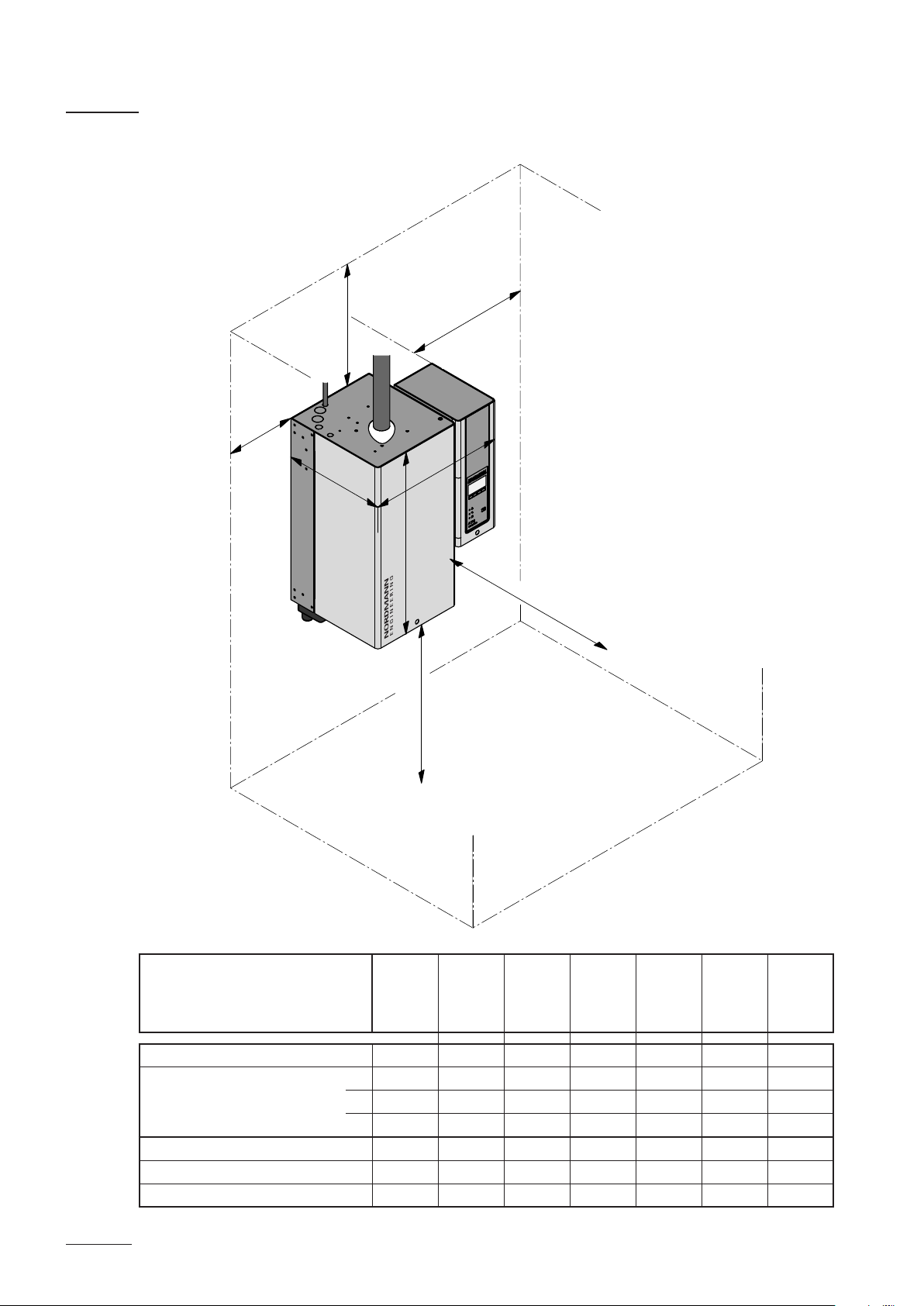
5.3.1 Notes on locating the unit
min. 400 mm
min. 100 mm
Y
min. 100 mm
X
Z
Cleo Premium Pro ...
min. 380 mm
522
524
532
534
822
824
832
834
min. 600 mm
1532
1534
2362
2364
3262
3264
4564 6564
22
Dimensions
Housing dimensions
in mm
Weights
Net weight in kg 12 12 19 19 28 28 30
Operating weight in kg 17 17 29 29 65 65 67
X 428 428 508 508 563 563 563
Y 255 255 345 345 354 354 354
Z 575 575 620 620 640 640 640

The installation site of the steam generator depends largely on the location
of the steam distributor (see chapter 5.4). To ensure proper functioning
of the steam generator and to obtain an optimal efciency, the following
points must be considered and observed when choosing the location for
the steam generator:
– Install the steam generator so that the length of the steam hose is kept
as short as possible (max. 4 m) and that the minimum bend radius
(R= 300 mm) and up-slope (20 %) or down-slope (5 %) of the steam
hose is observed (see chapter 5.4.5).
– The steam generators Cleo Premium Pro are designed for wall-mount-
ing. Make sure that the construction (wall, pillar, floor-mounted console,
etc.) to which the steam generators are to be mounted, offers a sufciently high load-bearing capacity (take notice of the weight informa-
tion found in the dimension sand weights table above), and is suitable
for the installation.
– The back panel of the Cleo Premium Pro is retaining heat during opera-
tion (max. surface temperature of the metal housing approx. 60 - 70 °C).
Make sure, therefore, that the construction (wall, pillar, etc.) to which
the unit is to be mounted, does not consist of heat-sensitive material.
– Install the steam generator in such a manner that it is freely accessible
with sufficient space available for maintenance purposes (refer to the
above illustration for minimum distances).
– The Cleo Premium Pro is protected according to IP21. Make sure the
units are installed in a drip-proof location and the admissible ambient
conditions are complied with.
– The steam generator Cleo Premium Pro may only be installed in rooms
with a floor drain.
CAUTION!
If for some reason the Cleo Premium Pro must be installed in a
location without floor drain, it is mandatory to provide a leakage
monitoring device to safely interrupt the water supply in case of
leakage.
– When fixing the Cleo Premium Pro use only the fixing materials sup-
plied with the unit. If fixing with the materials supplied is not possible in
your particular case, select a method of fixing that is of similar stability.
– The Cleo ES4 is designed for installation and operation within
buildings (admissible temperature range see chapter 6.1). For outdoor
operation the Cleo Premium Pro must be placed in a weather
protective housing. If ambient temperatures near or below the freezing
point have to be expected, the protective housing must equipped with a
thermostat controlled heating of sufficient capacity. The water supply
pipe must be equipped with a trace-heating and must be insulated up to
the protective housing.
23
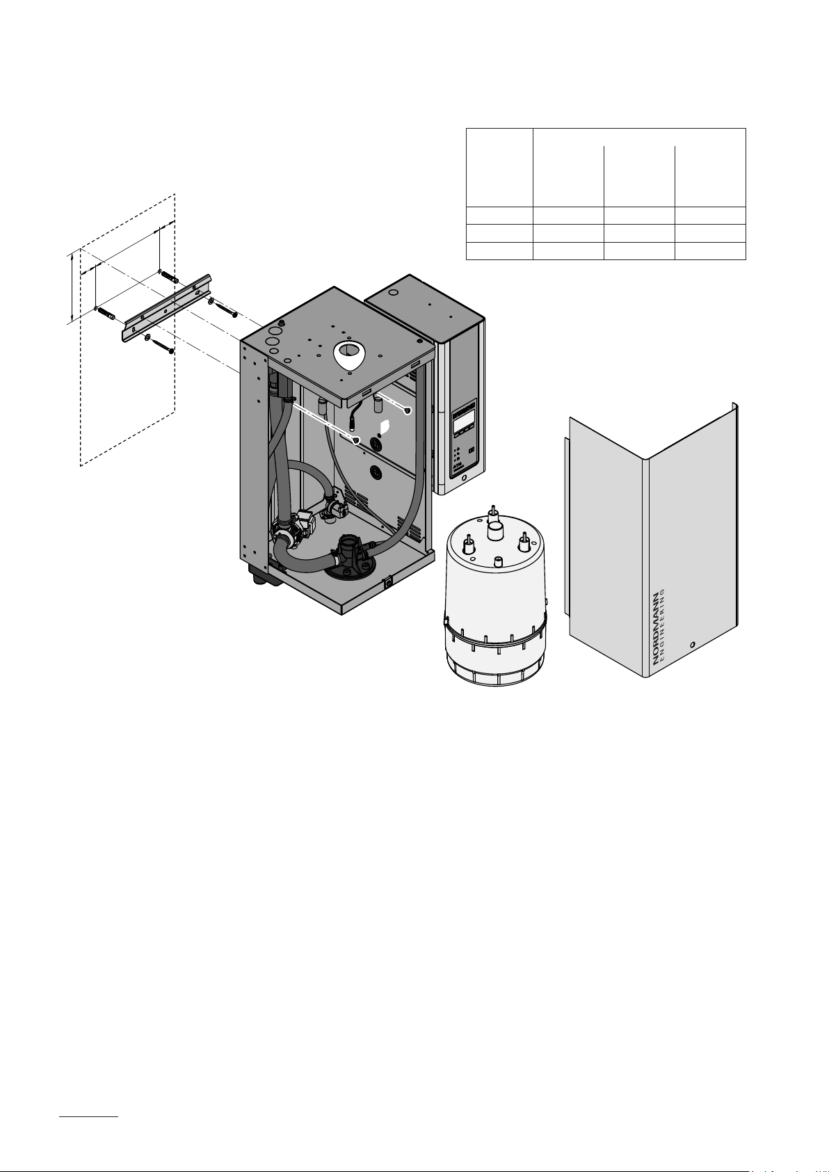
5.3.2 Mounting the steam generator
b
c
b
a
A
A
Dimension Unit type
522, 524,
532, 534,
822, 824,
832, 834
a 204,0 mm 205.0 mm 205.0 mm
b 40,0 mm 50.0 mm 52.5 mm
c 150,0 mm 210.0 mm 260.0 mm
BB
1532, 1534,
2362, 2364
3262, 3264,
4564, 6564
24
Procedure
1. Mark the attachment points “A” for the wall support at the desired position
with the help of a spirit level. Then, drill holes diameter: 8 mm, depth:
40 mm.
2. Insert the supplied plastic plugs, and fix the wall support to the wall with
the screws supplied. Before tightening the screws adjust wall support
horizontally using a spirit level.
3. Unlock the screw of the front panel (steam side), then remove the front
panel.
4. Unmount the steam cylinder (see Cleo Premium Pro operating
instruc-tions chapter 6.3.1).
5. Hang up the unit onto the wall support. Then, fix the unit to the wall
support using the supplied screws “B”.
6. Remount the steam cylinder (see Cleo Premium Pro operating
instruc-tions chapter 6.3.1).
7. Reattach the front panel and secure it with the screw.

5.3.3 Inspecting the installed unit
Check the following points:
Is the unit installed in the correct place (see chapter 5.3.1)?
Is the supporting surface stable enough?
Is the unit correctly aligned, vertically and horizontally?
Is the unit properly secured (see chapter 5.3.2)?
Has the front panel of the unit been relocated and correctly xed with
the screw?
25

5.4 Steam installation
5.4.1 Overview steam installation
DDS22
DDL22
W22
DDL35
W35
min. 20 %
+
KS10
min. 5 %
Rmin. 300 mm
min. 300 mm
–
DDS22
DDL22
W22
DDL35
W35
min. 5 %
Rmin. 300 mm
–
min. 20 %
+
Rmin. 300 mm
DS22
DS35
Ømin.
200 mm
min. 300 mm
26

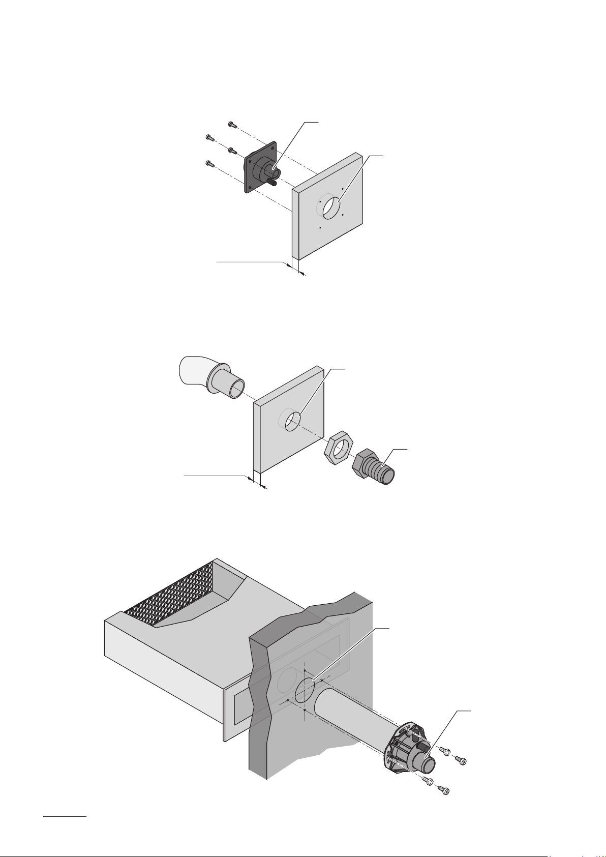
5.4.2 Positioning/mounting the steam distributor
It’s the responsibility of the customer to correctly position the steam distributor in the steam bath cabin.
WARNING!
Hot water vapour - Danger of scalding!
Shield the steam outlet of the steam distributor with corresponding meas-
ures to make sure steam bath users can not be burned by the steam ow.
Detailed information on the installation of steam distributors DDS..., DDL... and
W... can be found in the separate mounting instructions for these products.
ø22.5 mm
ø48.5 mm
DSL22
DSL35
max. 18 mm
DSS22
ø43 mm
max. 19 mm
DDL22: ø22.5 mm
DDL35: ø35 mm
W22: ø43 mm
W35: ø61 mm
W22
W35
W22: ø22.5 mm
W35: ø35 mm
27

5.4.3 Installing the steam and condensate hose
Important! Use original steam and condensate hose from Cleopatra B.V.
exclusively. Other types of hoses can cause undesired operational
malfunctions.
Instructions for the hose layout
The hose layout depends on the position of the steam distributor:
– Steam distributor is mounted more than 500 mm above the top edge
of the steam generator:
min. 20 %
+
min. 20 %
–
Rmin. 300 mm
min. 300 mm
Ømin. 200 mm
max. 4 m
min. 300 mm
Initially, lead the steam hose with an upslope of at least 20% over a
minimum height of 300 mm
, then lead the hose with a minimum
upslope of 20% and/or a minimum downslope of 5% to the steam
distributor.
28
The condensate hose is led down to the humidifier with a minimum slope
of 20 %, in the form of a siphon (min. hose bend diameter Ø200 mm)
and is to be connected to the appropriate connector on top of the unit.
Important! Before putting the unit into operation, the siphon of the
condensate hose must be filled with water.

– Steam distributor is mounted less than 500 mm above the top edge
of the steam generator:
min. 5 %
–
min. 20 %
+
Rmin. 300 mm
DS22
DS35
max. 4 m
min. 300 mm
Rmin. 300 mm
min. 20 %
+
Rmin. 300 mm
max. 4 m
Install condensate drain (accessory CD..)
at the lowest point
Obstacle
min. 5 %
–
Rmin. 300 mm
min. 20 %
–
Ømin.
200 mm
min. 300 mm
min. 20 %
+
Initially, the steam hose is led with an upslope of at least 20 % over
a minimum height of 300 mm above the top edge of the steam generator and then down to the steam distributor with a minimum slope
of 5 %.
Condensate hose of the condensate drain is led down with a minimum
slope of 20 %, in the form of a siphon (min. hose bend diameter Ø200
mm), directly into a discharge funnel.
Important! Before putting the unit into operation, the siphon of the
condensate hose must be lled with water.
29

– The steam hose should be kept as short as possible (max. 4 m) while
observing the minimum bend radius of 300 mm. Important! Allowance must be made for a pressure loss of approx. 100 Pa per meter
steam hose.
Note: If your particular installation exceeds the maximum steam hose
length of 4 m contact Cleopatra B.V. In any case, steam hoses longer
than 4 m must be insulated in their entire length (e.g. with insulation
hose “EcoTherm”).
– Reductions in the cross section such as kinks should be avoided through-
out the entire length
of the hose. The installation of a stop cock in the
steam hose is not permissible.
– Steam hoses must be prevented from sagging (condensate pockets); if
necessary, support with pipe clamps, trough, or wall brackets, or install
a condensate drain in the steam hose.
– Important! When deciding on the length and layout of the hose, it
should be noted that the steam hose may become somewhat shorter
with progressive ageing.
– Important note regarding the IP protection class: to meet the IP21
protection class the steam hose lead through on top of the housing must
be sealed with commercially available, heat resistant sealant.
Securing the hose
The
steam hose must be secured to the steam distributor and steam
gen-erator steam outlet by means of hose clamps.
Caution! Do not overtighten the hose clamp on the steam connector of the
steam generator.
30

Steam line with xed piping
For steam lines with xed piping, the same instructions apply to the laying
of the piping as already described.
min. 20 %
+
min. 5 %
–
Rmin. 5 x D
min. 300 mm
min. 20 %
+
Ømin.
200 mm
min. 300 mm
Rmin. 4 x D
The following additional notes should be observed:
– The minimum internal diameter of the steam line (diameter depend-ent
on the steam generator) should be applied over the whole length of the
piping.
– Use exclusively copper pipe or stainless steel (min. DIN 1.4301).
– To
minimize the condensate formation (=loss), the steam pipes must
be insulated.
– The minimum bend radius for solid pipes is 5 x internal diameter.
– Connection of the steam pipes to the steam distributor and steam gen-
erator is effected by means of short lengths of steam hose secured with
hose clamps.
– Important! Allowance must be made for a pressure loss of approx.
100 Pa per meter length or per 90° bend.
31
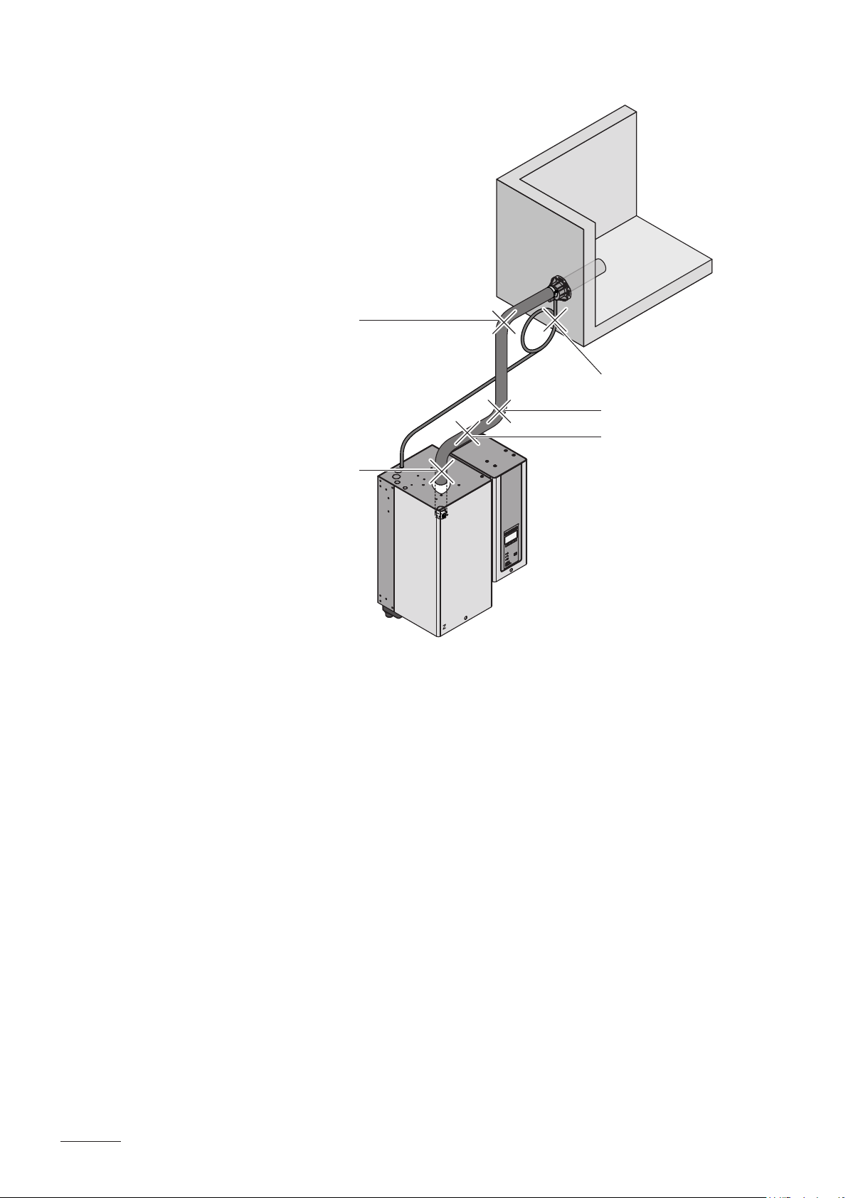
5.4.4 Common steam and condensate line errors
2.
1.
3.
4.
5.
1. Steam hose not led at least 300 mm perpendicularly upwards before
rst bend.
2. Minimum bend radius of steam hose of 300 mm not maintained (forming
of condensate).
3. Siphon of the condensate hose not at least 300 mm below the steam
distributor.
4. No condensate drain installed at vertical transition.
5 . Steam hose not sloped (slope min. 20 %).
32

5.4.5 Inspecting the steam installation
Use the following check list to ascertain that the steam installation was
performed correctly:
– Steam distributor
Steam distributors correctly positioned and secured (screws tightened)?
Are the outlet orices at right angles to the air ow direction?
– Steam hose
Maximum length of 4 m?
Minimum bend radius of 300 mm (5 x internal diameter with xed
piping)?
Have the instructions for hose positioning been followed?
Steam hose: no sagging (condensate pocket) or condensate drain
with siphon (hose bend with a minimum diameter of 200 mm) installed
at the lowest point?
Rigid steam lines: properly insulated? Correct installation material
used? Minimum internal diameter maintained?
Steam hose(s) securely attached with clamps?
Heat expansion during operation and shortening of the hose with
ageing taken into consideration?
Is the lead through of the steam hose on top of the unit sealed
(safeguarding of the IP21 protection)?
– Condensate hose
Downslope of at least 20 %?
Siphon (min. ø200 mm) existing and lled with water?
Condensate hose correctly xed and not kinked?
33
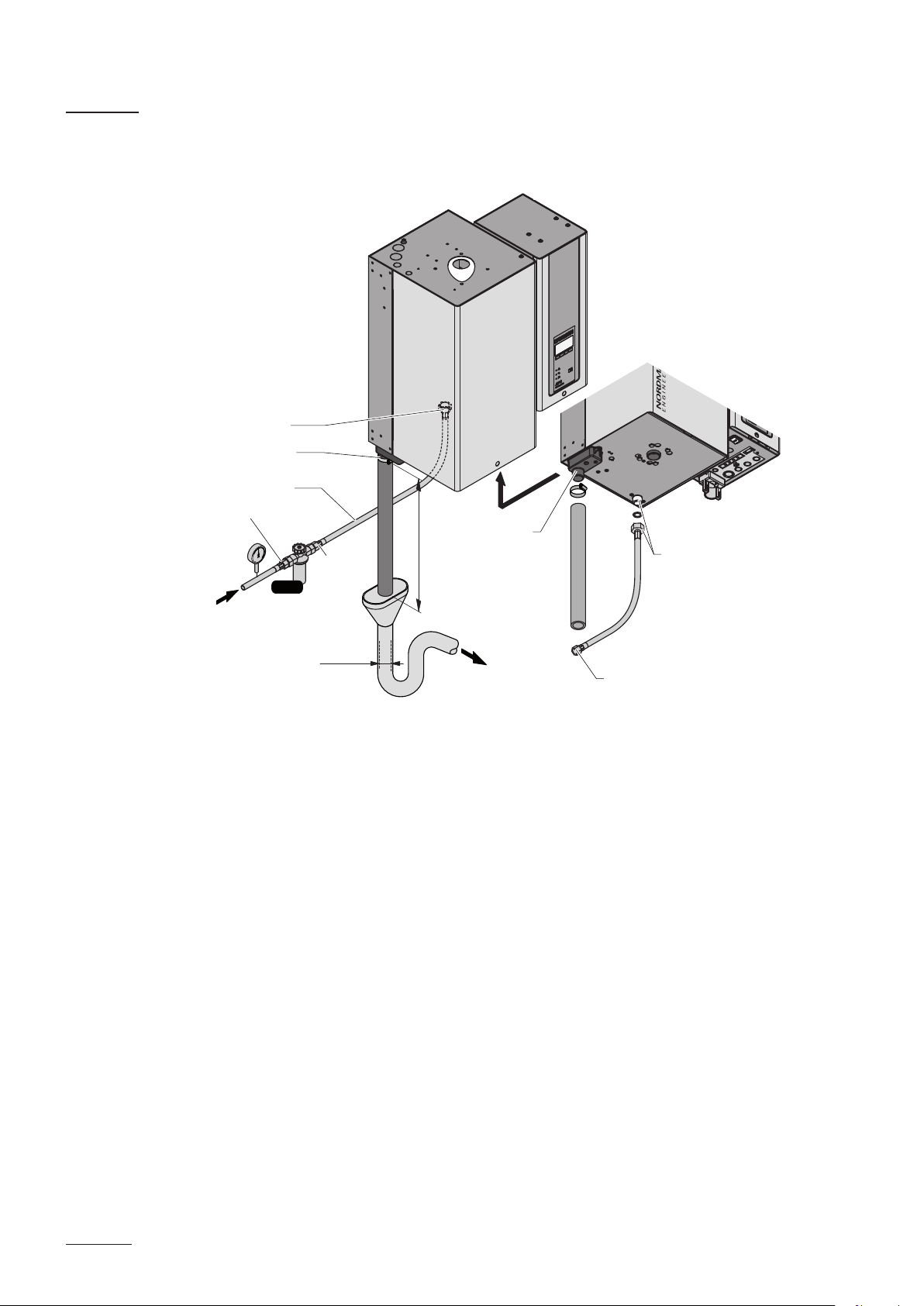
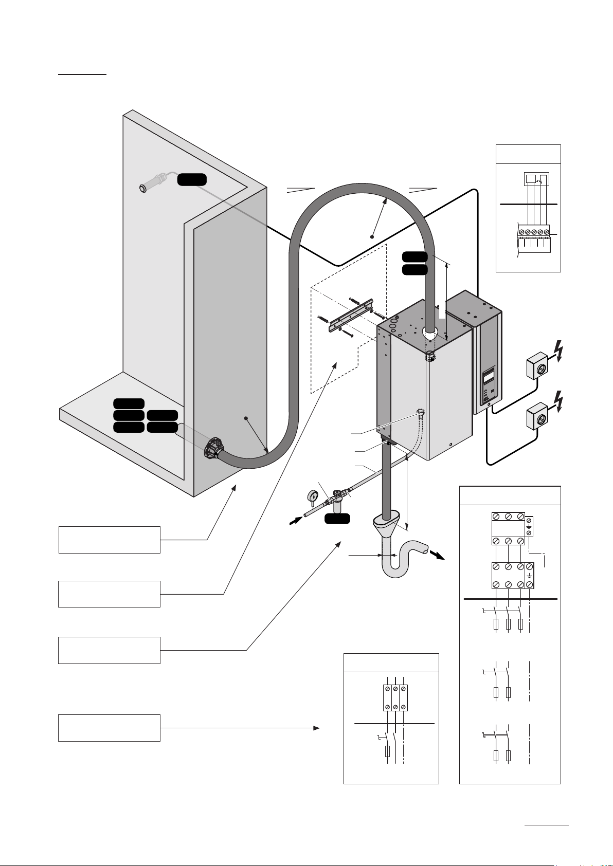
5.5 Water installation
5.5.1 Overview water installation
G 3/4"
ø 31 mm
ø14/7 mm
G 1/2"
125...1250 µS/cm
1...10 bar
1...40 °C
Z261
G 3/8"
≥ 40 mm
ø 31 mm
G 3/4"
min. 50 cm
G 3/8"
34

5.5.2 Notes on water installation
Water supply
The water supply is to be carried out according to the gure found in chapter
5.5.1 and the applicable local regulations for water installations. The indicated
connection specications must be observed.
– The installation of the filter valve (accessory “Z261”, alternatively a
shut-off valve and a 5 µm water filter can be used) should be made as
close as possible to the steam generator.
– Admissible mains pressure 1.0 to 10.0 bar (hammer-free system) For
mains pressures >10 bar, the connection must be made via a pres-sure
reducing valve (adjusted to 1.0 bar). For mains pressures <1.0 bar
please contact Cleopatra B.V.
– Notes on water quality:
– For the water supply of the Cleo Premium Pro, use exclusively
– The use of additives such as corrosion inhibitors, disinfectants,
– If the Cleo Premium Pro shall be operated with softened or
un-treated drinking water.
etc. is not allowed, since these additives may endanger health and
affect proper operation.
partly softened water, please contact Cleopatra B.V.
– The connection material must be pressure-proof and certified for use in
drinking water systems.
– Important! Before connecting the water line, the line should be well
flushed out.
CAUTION!
The thread at the steam generator connection is made of plastic.
To avoid overtightening, the union nut of the water pipe must be
tight-ened by hand only.
Water drain
The water drain is to be carried out according to the gure found in chapter
5.5.1 and the applicable local regulations for water installations. The indi-
cated connection specications must be observed.
– Make sure that the drain pipe is correctly xed and easily accessible for
inspections and cleaning purposes.
– The draining temperature is: 80…90 °C. Use temperature-resistant
installation materials only!
35

5.5.3 Inspecting the water installation
Check the following topics:
– Water supply
Has lter valve (accessory “Z261”) or shut-off valve and 5 µm water
lter respectively been installed in supply line?
Have admissible water pressure (1 – 10 bar) and admissible temperature (1 – 40 °C) been observed?
Does the supply capacity match the steam generator and is the
minimum inside diameter of the supply pipe maintained throughout
the entire length?
Are all components and pipes properly secured and are all threaded
connections securely tightened?
Is the water system properly sealed?
Does the water supply installation meet the requirements of the local
regulations for water installations?
– Water drain
Is the minimum inside diameter of the drain pipe of 40 mm maintained
throughout the entire length?
Has drain pipe been installed with a downslope of at least 10 %?
Has the heat resistance of the material used been veried to be at
least 100 °C?
Is the drain hose properly secured (hose clamps at unit connection
tightened)?
Does the water drain installation meet the requirements of the local
regulations for water installations?
36
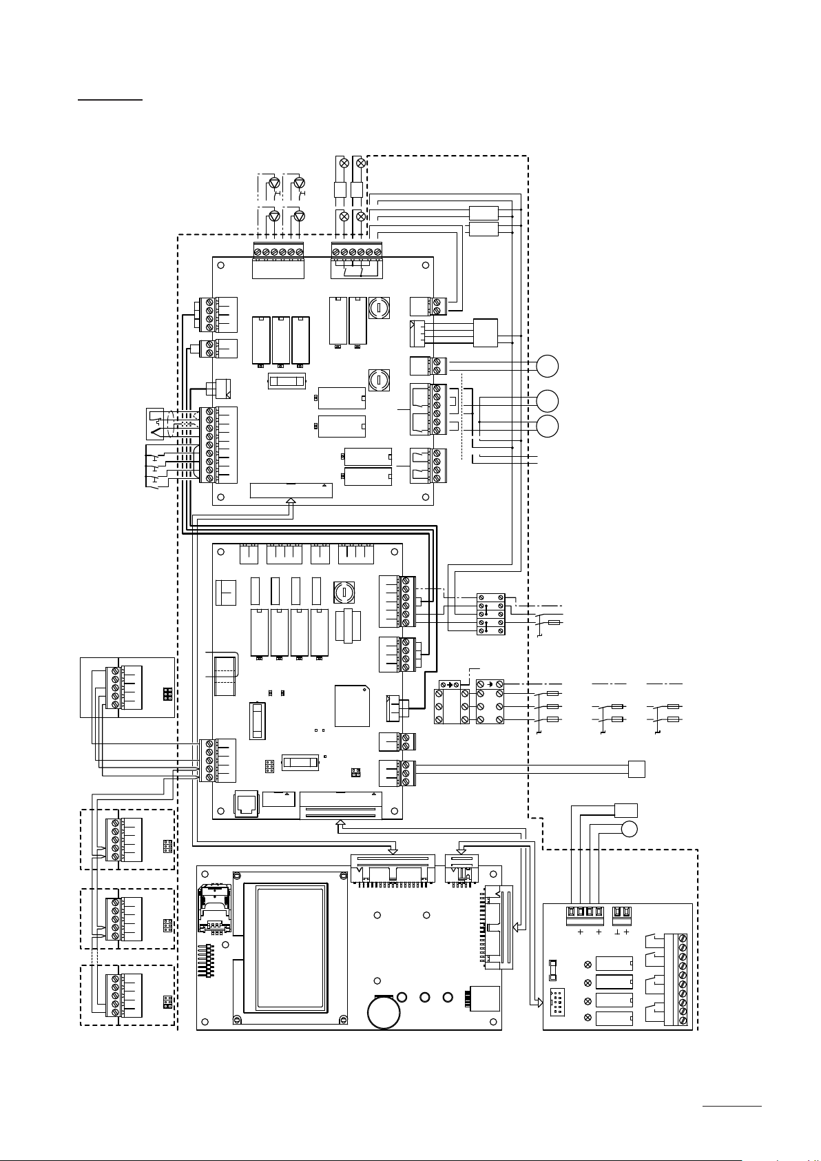
5.6 Electric installation 5.6.1
Wiring diagram Cleo Premium Pro
max. 2m
H3
Mode
External
M2
Internal
Mode
M1
M2
M1
230V
T4
24V
12V
H3
H2
12V 12V
230V 230V
T4
H2
230V
12V
24V
T3 T2
Supply Light
230V 12V
230V 24V
Premium Pro
L N
ext.
Remote Terminal
Unit 2Unit 3Last Unit
switch
Excess temperature
Temperature sensor
SW4
SW3
SW2
SW1
X15
D+ D– GND 5V 24V
X15
D+ D– GND 5V 24V
A5
JP5
JP4
JP1
JP5
JP4
JP1
board
X6
Steam bath
P
N
P1
PE
X24
SC2
SC1
X14
X31
J3J4
X5
Power board
from contactor to cylinder
X15
1234
MODULE B
21
8 A 250 VAC
SAFETY CHAIN
5VGND24V
EXT. SUPPLY IN
TEMP S
1234 5678 9
24V
GND
TEMP IN
24V
LIGHT 2
LIGHT 1
BATH I/O
INPUTS
DOOR
X3
L'N
S1S2
LEVEL SENS.
CURRENT SENSOR
F4 315mAT
JP5
JP4
REMOTE
JP1
D+ D– GND 5V 24V
LINK UP
J2
X22
L' L'N NPE PE
PUMP 1 PUMP 2
8 A 250 VAC
8 A 250 VAC
8 A 250 VAC
F6
315mAT
CPU BOARD
J3
X4
L'NL'N
X16
L1FUNL1SWNSW
L'N
INLET DRAIN CONTA.
SC
F1 6.3 AT
CONTACTORDRAININLETSC SYSTEM
SAFETY CHAIN
LEVEL SENSOR
GND
24V
F3 315mAT
5V
EXTERNAL CON.CPU BOARD
J4
24V 5V
LIGHT 1 LIGHT 2LIGHT IN
8 A 250 VAC
8 A 250 VAC
8 A 250 VAC
SWITCH
JP3
L NN LL N
F5
24V: 4AT
230V: 1AT
F7
4AT
8 A 250 VAC
8 A 250 VAC
X2
PEPESC2SC1NL1
MAIN SUPPLYMODULE B
PEP1NP
EXT. SUP.
5V GND 24V
GNDIN
LIM. SIGN.
GNDINV+
CONT. SIGN.
X21
12V: 6.3AT
2-Fan Mode
J1
FAN 0V
LIGHT SUPPLY OUT
24V 0V18V15V
EXT. TRAFO IN
FAN 0VAC
1-Fan Mode
FAN 2
FAN 1
NO NOAUX1 AUX2COM COM
REL8 REL9
COM NO COM NO
X1
X6
X14
X11
X10
X27
J2
X26
X25
X23
(Light 24 V)
Supply FAN
24V
T1
0V
15V
18V
230V
24V
Mode
1-Fan
Mode
1-Fan
Mode
2-Fan
PE
N
N
L1
L1
XE3
L N L N LL N N
24V / 12V
M3 M4 M5
Q9
M3 Exhaust air fan 1 (2 fan mode)
FAN
FAN 2
FAN 1
Supply on site
M4 Supply air fan 2 (2 fan mode)
(Supply)
(Exhaust)
(4 A, slow acting)
F7 Internal fuse “steam bath board” Fan
L N PE
F9
230 V/1~/50..60 Hz
M5 Fan (1 fan mode)
Q8 External service switch heating voltage supply
Q9 External service switch control voltage supply
SW1 Door switch steam bath cabin
SW2 On/Off push-button steam bath cabin
SW3 On/Off push-button light 1
SW4 On/Off push-button light 2
T1 Transformer voltage supply fan
T2 Transformer voltage supply light (230V/12V)
T3 External transformer voltage supply light (230V/12V)
XE1 Connection terminal heating voltage
XE3 Connection terminal control voltage
X15 Connection terminal remote panel
U1 External temperature indication (0...10 V / 0...100 °C)
U2 Flap actuator (0...10 V / open...closed)
switch is connected
F8 External fuse heating voltage supply
F9 External fuse control voltage supply
H1 Remote operating and fault indication
H2 Light 1
H3 Light 2
J3 Short circuited, if no excess temperature
J4 Short circuited, if no door switch is connected
JP1 End resistor Remote Terminal
JP3 Jumper control signal
JP4 Pull up resistor Remote Terminal
JP5 Pull down resistor Remote Terminal
K1 Main contactor
M1 Fragrance pump 1
M2 Fragrance pump 2
PE
PE
L1 L2 L3
L1 L2 L3
K1
XE1
Q8
L1 L2 L3
400 V/3~/50..60 Hz
F8
230 V/3~/50..60 Hz
PE
L1 L2
F8
Q8
+ –
Temperature or Humidity in
400 V/2~/50..60 Hz
F8
Q8
A6
L1 N PE
230 V/1~/50..60 Hz
24 V supply (315 mA, slow acting)
Light (230 V: 1 A, slow acting,
24 V: 4 A, slow acting, 12 V: 6.3 A, slow acting)
F6 Internal fuse “steam bath board”
F5 Internal fuse “steam bath board”
U1U2
X15
JP5
JP4
JP1
D+ D– GND 5V 24V
X15
JP5
JP4
JP1
D+ D– GND 5V 24V
J9
Control board
J3
BAT
J2
J1
J4
Temperature out
X4X5
H1
F1
0...10V / 0...100°C
4321
100mA
J1
Flap motor
0...10V / open...closed
21
Max. 60mA
Sensor Supply
X1
Unit ONSteamServiceError
1 2 3 4 5 6 7 8 9 10
A5 Temperature sensor with excess temperature switch (e.g. KTY)
A6 Temperature sensor 0...10 V
BAT Backup battery (CR2032, Lithium 3V)
F1 Internal fuse “Power board” (6.3 A, slow acting)
F3 Internal fuse “Power board” 24 VDC supply (315 mA, slow acting)
F4 Internal fuse “Power board” 5 VDC supply (315 mA, slow acting)
37

5.6.2 Notes on electric installation
Important notes
– The electric installation must be carried out according to the wiring dia-
gram in chapter 5.6.1, the notes on electric installation as well as the
applicable local regulations. All information given in the wiring diagram
must be followed and observed.
– All cables must be lead into the unit via the cable openings equipped with
cable glands (e.g. option “CG-cable gland”). The cable for the heating
voltage supply must be lead into the unit from the bottom via the cable
opening equipped with the clamp strap. Fix the cable with the clamp
strap.
– Make sure the cables do not scrub on any components or become a
stumbling trap.
– Maximum cable length and required cross section per wire must be
observed.
– The supply voltages must match the respective voltages (heating and
control voltage) stated in the wiring diagram.
38
Heating voltage supply
CAUTION!
Before connecting, ensure that the mains voltage corresponds with
the
heating voltage for the unit (see type plate).
The connection to the heating voltage is made in accordance with the wiring diagram, to the terminal block “XE1” in the control compartment. The
customer is to install a service switch “Q8” (disconnecting device with a
minimum contact opening of 3 mm is an essential requirement) and a fuse
group “F8” (essential requirement, fuses are to be as detailed in the fol-
lowing table) in the supply line. The supply wiring is to be fed into the
unit via the clamp strap on the bottom of the unit.
Heating voltage Max. steam
capacity
[kg/h]
400V3
(400 V/3~/50...60 Hz)
400V2
(400 V/2~/50...60 Hz)
230V3
(230 V/3~/50...60 Hz)
230V1
(230V/1~/50...60Hz)
15 1534 11.3 16.2 3x 25
23 2364 17.3 24.9 3x 35
32 3264 24.0 34.6 3x 50
45 4564 33.8 48.7 3x 80
65 6564 48.8 70.4 3x 100
15 1532 11.3 28.2 3x 40
23 2362 17.3 43.3 3x 63
32 3262 24.0 60.2 3x 100
The cross-section of the mains cable must comply with the applicable local
regulations.
Cleo
AT4 ..
5 534 3.8 5.4 3x 10
8 834 6.0 8.7 3x 16
5 524 3.8 9.4 3x 16
8 824 6.0 15.0 3x 25
5 532 3.8 9.4 3x 16
8 832 6.0 15.1 3x 25
5 522 3.8 16.3 25
8 822 6.0 26.1 40
Nominal power
[kW]
Nominal
current
[A]
Main fuses F8
[A]
39

Control voltage supply
CAUTION!
– Before connecting, ensure that the mains voltage corresponds with
the
control voltage of the unit (230 V/1 50…60 Hz).
– The steam generator must only be connected to a mains supply with a
protective conductor.
The connection to the control voltage is made in accordance with the wiring diagram, to the terminal block “XE3” in the control compartment. The
customer is to install a service switch “Q9” in the supply line (all pole disconnecting device with a minimum contact opening of 3 mm) and an “F9”
fuse (max. 10 A slow acting) (these are both essential requirements).
The cross-section of the mains cable must comply with the applicable
local regulations (minimum of 1.5 mm2).
Remote operating and fault indication H1 (Option “RFI”)
The remote operating and fault indicators must be connected to the respective potential-free relay contacts of
the remote indicator board according to
the wiring diagram:
– “Error”: This relay is activated if an error is present.
– “Service”: This relay is activated when the set service interval has
expired.
– “Steam”: This relay closes as soon as the unit produces steam.
– “Unit On”: This relay closes as soon as the unit is switched on via the
unit switch.
The maximum contact loading is 250V/8A.
Appropriate suppressor modules are to be used for the switching of relays
and miniature contactors.
Remote temperature indication (U1)
Analogue output 0...10 V (0...100 °C) for remote temperature indication.
Analogue output ap actuator U2
Analogue output 0...10V (open...closed) for the control of the ap actuator.
The ap actuator is connected to the appropriate terminals on the remote
operating and fault indication board according to the wiring diagram. The
output signal is always active.
The cross-section of the connecting cable must comply with the applicable
local regulations.
40
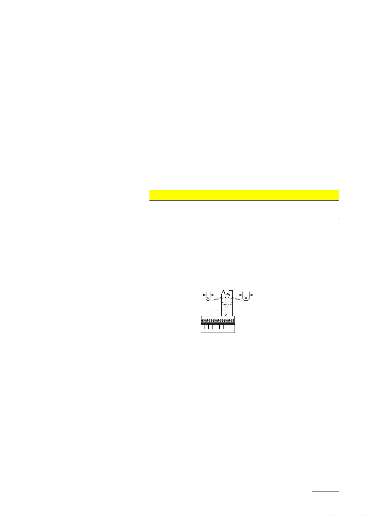
Temperature control and monitoring (A5)
4.8 mm2.8 mm
X31
TEMP S
24V
GND
TEMP IN
24V
LIGHT 2
LIGHT 1
BATH I/O
DOOR
1234 5678 9
A5 (KTY)
ext.
– Temperature sensor
The temperature sensor is connected to the terminals “TEMP IN” (+) and
“GND” (–) of terminal bloc “X31” on the steam bath board. The steam
bath board is ready for the connection of these types of temperature
sensors, hence not further adjustments are required.
The temperature sensor must be installed in a appropriate location inside
the steam bath (away from the steam exit).
Please refer the separate installation instructions for proper location and
connection of the temperature sensor.
– Excess temperature switch
An excess temperature switch for the monitoring of the maximum steam
bath temperature is connected to the terminals “24V” and “TEMP S” of
terminal bloc “X31” on the steam bath board.
If, for whatever reason, no excess temperature switch is connected,
the terminals “24V” and “TEMP S” must be short circuited using a cable
bridge “J3”.
CAUTION!
Do not apply any extraneous voltage to the terminals “24V” and
“TEMP S”.
The cross-section of the connecting cable must comply with the applicable
local regulations.
We recommend the use of a shielded cable for the connection of the temperature sensor and the excess temperature switch.
– Wiring diagram temperature sensor KTY with integrated excess
temperature switch (accessory)
Premium Pro
External temperature signal 0-10V (A6
Alternatively to the temperature sensor KTY an external 0-10V signal from
a building management system or from a separate temperature sensor can
be used to control the
steam bath temperature. The 0-10 V signal is con-
nected to the terminals “IN” (+) and “GND” (–) of terminal bloc “X10” on the
power board. The configuration of the control signal is made via the
control software of the Cleopatra Premium Pro.
41

Fragrance pump M1 and M2 (230VAC)
The fragrance pumps are connected to the appropriate terminals of terminal
bloc “X22” on the steam bath board according to the wiring diagram. The
connection layout is dependent on the operating mode (internal or external
control) of the fragrance pumps.
The cross-section of the connecting cable must comply with the applicable
local regulations.
Steam bath lighting H2 and H3
The steam bath lighting (Light 1 and Light 2) is connected to the appropriate
terminals of terminal bloc “X21” on the steam bath board according to the
wiring diagram. The voltage supply of the steam bath lighting is made dependent on the used illuminant either via the internal 230 VAC supply or via the
optional transformers T1 (230V/24V), T2 (230V/12V) or T3 (230V/24V)
The cross-section of the connecting cables must comply with the applicable
local regulations.
230 V voltage supply 12 V voltage supply
XE3
230V
230V
H3
H2
8 A 250 VAC
8 A 250 VAC
F5
230V: 1AT
24V: 4AT
12V: 6.3AT
EXT. TRAFO IN
24V 0V18V15V
J2
N
N
L1
L1
PE
LIGHT 1 LIGHT 2LIGHT IN
LIGHT SUPPLY OUT
FAN 0V
X27
L NN LL N
X21
L N
max. 2m
T4
H3
T4
H2
12V 12V
230V 230V
XE3
N
N
L1
L1
PE
Premium Pro
Q9
F9
L N PE
230 V/1~/50..60 Hz
ext.
Q9
F9
L N PE
230 V/1~/50..60 Hz
24 V voltage supply (variant 1) 24 V voltage supply (variant 2)
24V
H3
H2
XE3
N
N
L1
L1
PE
Q9
F9
XE3
8 A 250 VAC
8 A 250 VAC
F5
230V: 1AT
24V: 4AT
12V: 6.3AT
EXT. TRAFO IN
24V 0V18V15V
J2
24V
N
N
L1
L1
PE
18V
230V
L N
LIGHT SUPPLY OUT
FAN 0V
0V
15V
Supply FAN
T1
X27
24V
(Light 24 V)
LIGHT 1 LIGHT 2LIGHT IN
L NN LL N
X21
24V
Premium Pro
Q9
F9
ext.
8 A 250 VAC
8 A 250 VAC
F5
230V: 1AT
24V: 4AT
12V: 6.3AT
EXT. TRAFO IN
24V 0V18V15V
J2
8 A 250 VAC
8 A 250 VAC
F5
230V: 1AT
24V: 4AT
12V: 6.3AT
EXT. TRAFO IN
24V 0V18V15V
J2
LIGHT 1 LIGHT 2LIGHT IN
LIGHT SUPPLY OUT
FAN 0V
X27
LIGHT 1 LIGHT 2LIGHT IN
LIGHT SUPPLY OUT
FAN 0V
X27
12V
H3
H2
L NN LL N
X21
12V
T2
230V 12V
L N
Premium Pro
ext.
24V
H3
H2
L NN LL N
X21
24V
T3
230V 24V
L N
Premium Pro
ext.
42

Steam bath fans M3/M4 (2-Fan mode) and M5 (1-fan mode)
– 2-fan mode
8 A 250 VAC
8 A 250 VAC
F7
4AT
2-Fan Mode
FAN 1
FAN 2
XE3
NO NOAUX1 AUX2COM COM
X25
N
N
L1
L1
PE
24V / 12V
1-Fan Mode
FAN 0VAC
X26
Mode
2-Fan
EXT. TRAFO IN
24V 0V18V15V
J2
LIGHT SUPPLY OUT
FAN 0V
X27
Cleo Premium Pro
Q9
F9
L N PE
230 V/1~/50..60 Hz
Supply on site
M3 M4
FAN 1
(Exhaust)
FAN 2
(Supply)
ext.
The fans M3 (exhaust air) and M4 (supply air) are connected to the
appropriate terminals of terminal bloc “X25” on the steam bath board.
The voltage supply of the fans is made either via the internal 230 VAC
supply or an external 12 V or 24 V supply.
– 1-fan mode (three-stage)
8 A 250 VAC
8 A 250 VAC
F7
4AT
2-Fan Mode
FAN 1
FAN 2
XE3
NO NOAUX1 AUX2COM COM
X25
N
N
L1
L1
PE
1-Fan Mode
FAN 0VAC
X26
Mode
1-Fan
EXT. TRAFO IN
24V 0V18V15V
J2
Mode
1-Fan
L N
24V
230V
15V
18V
LIGHT SUPPLY OUT
FAN 0V
0V
(Light 24 V)
Supply FAN
T1
X27
Cleo Premium Pro
Q9
F9
L N PE
230 V/1~/50..60 Hz
M5
FAN
ext.
The three-stage fan M5 is connected to the appropriate terminals of
terminal bloc “X26” on the steam bath board. The voltage supply of the
fan M5 is made via the optional transformer T1.
For 1-fan mode (three stage) terminal bloc “X25” must be equipped with
cable bridges as shown in the wiring diagram.
The cross-section of the connecting cables must comply with the applicable
local regulations.
43

Switch SW1 and push-buttons SW2...SW4
The switch SW1 (door switch) and the push-buttons SW2 (steam bath On/
Off), SW3 (Light 1 On/Off) and SW4 (Light 2 On/Off) are connected to the
appropriate terminals of terminal bloc “X31” on the steam bath board.
Note: If no door switch (SW1) is connected the terminals “DOOR” and “24V”
must be short circuited using a cable bridge.
The cross-section of the connecting cable must comply with the applicable
local regulations.
Connection of the remote terminal (Option RP)
The optional remote terminal is to be connected via a four-wire cable to the
corresponding contacts of terminal block X15 on the power board of one
of the humidiers.
Addtional humidiers (max. 8) to be remote controlled are connected in
series via the contacts “D+” and “D–” of terminal block X15 to the humidier
connected to the remote terminal using a two-wire cable.
The maximum cable length between the units is 50 m. Cable section
0.5 mm2.
The termination of the remote terminal bus is established via the jumpers
JP1, JP4 and JP5 on the power boards of the remote terminal and the con-
nected humidiers (see table below).
Jumper settings for operation with optional remote terminal
Jumper Function Remote terminal Unit(s)
Last unit in
in between
JP1 120Ω end resistor X X
JP4 Pull up resistor X
JP5 Pull down resistor X
D+ D– GND 5V 24V
JP1
JP4
JP5
Unit 2Unit 3Last Unit
JP1
JP4
JP5
X15
D+ D– GND 5V 24V
REMOTE
LINK UP
JP1
JP4
JP5
EXTERNAL CON.
X15
D+ D– GND 5V 24V
JP1
JP4
X15
D+ D– GND 5V 24V
JP5
Remote Terminal
D+ D– GND 5V 24V
from contactor to cylinder
X15
F4
315mAT
JP1
JP4
JP5
CURRENT SENSOR
X15
the chain
ext.
Cleo Premium Pro
44

Internal control voltage supply via option CVI
– Option CVI (mains supply with neutral lead):
For mains voltages of 400 V/3~/50...60 Hz, 400 V/2~/50...60 Hz and
230 V/3~/50...60 Hz. The option CVI is connected according to the following wiring diagram.
F1 6.3 AT
L1FUNL1SWNSW
SWITCH
MAIN SUPPLYMODULE B
PEP1NP
X6
X1
PEPESC2SC1NL1
X2
L1 L2 L3
K1
Cleo Premium Pro
ext.
5.6.3 Inspecting the electrical installation
Check the following points:
Do the supply voltages for heating and control comply with the relevant
voltages given in the wiring diagram?
Is the correct CF Card inserted?
Are the voltage supplies (heating and control voltage) correctly fused?
F7
6.3 AT
Q5
F5
Q5
F5
L1 L1 L2 L3 N PE
N PE
L1 L2 L3
400 V/3~/50..60 Hz
230 V/3~/50..60 Hz
L1 L2
400 V/2~/50..60 Hz
XE1
PEN
Are the service switches “Q..” installed in the supply lines for to the
heating and control voltage?
Are all components correctly connected according to the wiring diagram?
Are all connecting cables fastened?
Are the connecting cables free of tension (passed through cable
glands?)
Does the electric installation meet the applicable local regulations for
electric installations?
Is the unit reassembled correctly and the front panel of the control
compartment xed with the screw?
45

6 Product specications
6.1 Technical data
Steam capacity in kg/h 5 8 15 23 32 45 65
Capacity range in kg/h 1...5 1.6...8 3...15 4,6...23 6,4...32 9...45 13...65
Nominal power in kW 3,8 6,0 11,3 17,3 24,0 33,8 48,8
Heating voltage 230V/1~/50..60Hz *
Unit model 522 822
Nominal current in A 16,3 26,1
Steam cylinder type ** 522A 822A
Heating voltage 400V/2~/50..60Hz *
Unit model 524 824
Nominal current in A 9,4 15,0
Steam cylinder type ** 524A 824A
Heating voltage 230V/3~/50..60Hz *
Unit model 532 832 1532 2362 3262
Nominal current in A 9,4 15,1 28,2 43,3 60,2
Steam cylinder type ** 532A 832A 1532A 2362A 3262A
Heating voltage 400V/3~/50..60Hz *
Unit model 534 834 1534 2364 3264 4564 6564
Nominal current in A 5,4 8,7 16,2 24,9 34,6 48,7 70,4
Steam cylinder type ** 534A 834A 1534A 2364A 3264A 4564A 6564A
Steam cylinder type *** 534A-L 834A-L 1534A-L 2364A-L 3264A-L 4564A-L ---
Control voltage 230 V/1~/50..60 Hz
Operating conditions
Admissible water pressure 1...10 bar
Water quality Untreated drinking water with a conductivity of 125...1250 µS/cm
Admissible water temperature 1...40 °C
Admissible ambient temperature 1...40 °C
Admissible ambient humidity max. 75 %rF (non condensing)
Admissible air pressure in the steam bath cabin -0.8 kPa...1.5 kPa
Type of protection IP21
Conformity CE, VDE, GOST
Dimensions/Weights
Width in mm 428 428 508 508 563 563 563
Height in mm 575 575 620 620 640 640 640
Depth in mm 255
Net weight in kg 12 19 28 30
Operating weight in kg 17 29 65 67
Water supply connector G 3/4" (male thread)
Water drain connector ø 31 mm (outside diameter)
Steam connector 1x ø 22 1x ø 35 2x ø 35
Options
Cable gland 1x CG
Steam hose connector with condensate trap 1x CT22 1x CT35 2x CT35
Internal control voltage supply 1x S-CVI 1x M-CVI 1x L-CVI
@Link Cleo Premium Pro @Link Cleo Premium Pro
Accessories
Filter valve 1x Z261
Cleo Premium Pro Remote Terminal
Cleo Premium Pro Touch Screen Panel
Temperature sensor KTY KTY
Steam distributor 1xW22 1xW35 2xW35
Fragrance pump 1xFP 240V
T-piece for fragrance injection 1xTSD22 1xTSD35 2xTSD35
Steam hose / meter 1xDS22 1xDS35 2xDS35
Condensate hose / meter KS10
Condensate drain 1xCD22 1xCD35 2xCD35
EcoTherm insulation hose 1xECT22 1xECT60 2xECT60
50-210VA transformer for 4x50W lamps TRL
* Other heating voltages on request
Steam cylinder for water conductivity from 125 to 1250 µS/cm (standard version)
**
*** Steam cylinder for low water conductivity from 80 to 125 µS/cm
255 345 345 354 354 354
RP
TSP
46

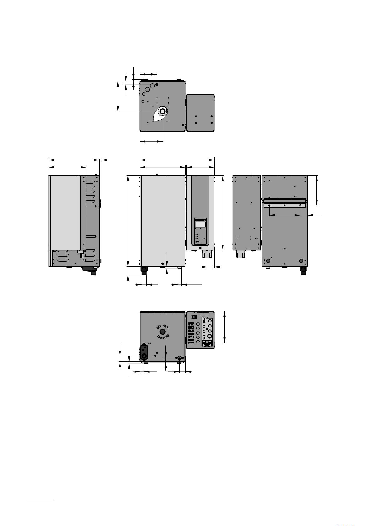
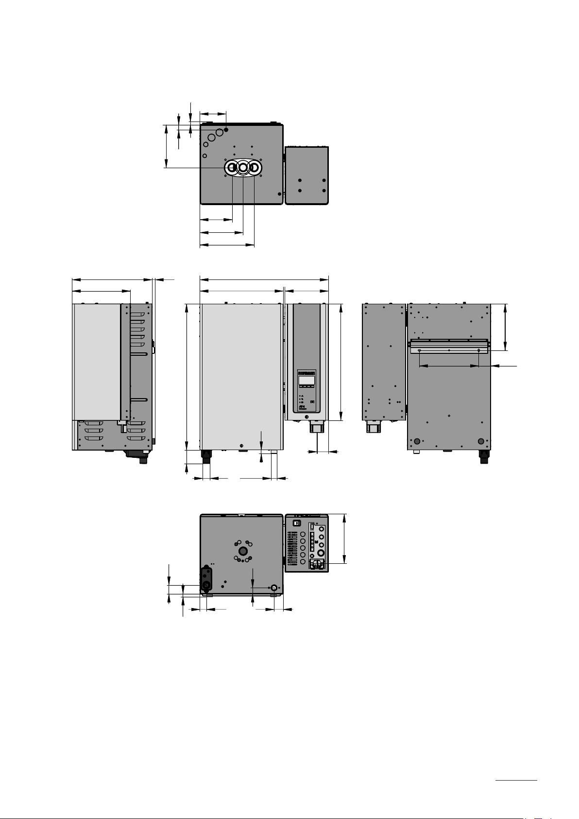
6.2 Unit dimensions
255
Cleo Premium Pro 5../8.. (Dimensions in mm)
13
115
26
164
124
428
13
230 190
204
42
13
575
60
29
31
30
16
G 3/4”
40
50
510
217
150 40
47
Cleo Premium Pro 15../23.. (Dimensions in mm)
13
115
26
209
155
255
345
13
620
60
508
310 190
16
31
G 3/4”
50
510
217
205
210 50
48
42
13
29
30
40
191
26
13
Cleo Premium Pro 32../4564/6564 (Dimensions in mm)
115
142
190
238
255
354
13
563
365 190
205
260 52.5
510
640
16
50
60
31 G 3/4”
217
42
13
29
30
40
49

Notes

© Cleopatra B.V.
º Technical modifications
reserved

Cleopatra B.V.
Oostzijde 295
1508 EN Zaandam
Nederland
+31 (0)75 647 8200
info@cleopatra.nl
www.cleopatra.nl www.cleopatra-wellness.com
 Loading...