

Page 1

CLEODE - Headquarter: 3, rue Thomas Edison - 223 00 LANNION– France
T. +33 (0 )2 96 4 8 68 18 - F. +33 (0 )2 96 4 8 19 11
SA w ith capital of 167,200 € - 450 570 767 RCS Sa int Brieuc
User
Manual
ZGAS
Smoke detector
and CO detector ZigBee®
Revision : 6
date : 10/22/2014
Status : Approved
Reference : UM_ZGAS_20090803_001_06_00
Page 2

User Manual : ZGAS
CLEODE
page 2 sur 21
Warranty
The device supplied to the buyer and/or the recipient is guaranteed by CLEODE against
any malfunctions originating from a design and/or manufacturing flaw, for a period of
twelve (12) months following delivery. The buyer and/or recipient is (are) responsible
for proving the existence of the said defects or flaws. This warranty is applicable in
accordance with articles 1641 to 1648 of the French Civil Code and in compliance with
the French statutory warranty. The warranty covers the replacement free of charge of
devices and parts affected by a design and/or manufacturing flaw excluding conspicuous
defects in the device that are covered by the buyer and/or the recipient
In order to invoke the warranty, the buyer must immediately send written notice to
CLEODE of the flaws that it attributes to the device. It must enable CLEODE to have
access to the device to observe these defects and repair them. The warranty provided by
CLEODE is strictly limited to the equipment provided and shall only have for effect the
replacement or repair, at CLEODE’s expense, on its own premises, of all devices or
parts that are not functioning as a result of defects or flaws. CLEODE reserves the right
to modify the devices in order to comply with the warranty.
The warranty does not apply to replacement or repairs that may result from normal wear
and tear of devices, systems or products, damage or accidents resulting from negligence,
failure to supervise or maintain, or incorrect use of the devices, systems and/or products.
The maintenance service is provided by CLEODE with all reasonable care possible and
in compliance with the current state of the arts.
The exchange of parts or repairs performed under the warranty cannot result in
extending the length of the warranty. In no event can the unavailability of the device due
to servicing give rise to compensation for any reason whatsoever. The seller is released
from all obligations relating to the warranty if the product or device has been modified
without prior written consent, or if original parts have been replaced by parts which it
has not manufactured without prior consent. If unforeseen damage is caused by the
device, it is expressly agreed that the seller can only be liable for the reimbursement of
monies received for the purchase of the device if it has been destroyed. Under no
circumstances can the seller be held liable for indirect or contingent damage. The seller
is released from any liability and the buyer waives any rights against it if an accident or
direct or indirect damage is caused to the buyer following a defect, incorrect usage,
incorrect maintenance or normal wear of the device sold.
Page 3
User Manual : ZGAS
CLEODE
page 3 sur 21
Revision table
Version
Author(s)
Description of the version
Date
0.1
Cleode
Initial version
08/03/2009
1.0
Cleode
Validated document
08/06/2009
1.1
Cleode
Minor corrections
09/04/2009
2.0
Cleode
Validated document
09/04/2009
2.1
Cleode
Add Technical features chapter
09/25/2009
3.0
Cleode
Validated document
09/25/2009
3.1
Cleode
Modification of autonomy period
01/05/2010
4.0
Cleode
Validated document
01/05/2010
4.1
Cleode
Modification of battery management
05/20/2011
5.0
Cleode
Validated document
05/20/2011
5.1
Cleode
Update manual
10/13/2014
6.0
Cleode
Validated document
10/22/2014
Page 4
User Manual : ZGAS
CLEODE
page 4 sur 21
Reference documents
N°
Document
Description
[1]
ZigBee_Cluster_Library_Public
ZigBee Cluster Library specification
[2]
ZigBee_Specification
ZigBee specification
[3]
ZigBee_Home_Automation
Home Automation profile specification
Page 5
User Manual : ZGAS
CLEODE
page 5 sur 21
Table of content
I. INTRODUCTION AND SPECIFICATIONS 7
I.1 INTRODUCTION 7
I.2 MEANING OF THE LIGHT INDICATOR 8
I.3 SPECIFICATIONS 8
II. ‘QUICK START’ 9
III. PROCEDURES 10
III.1 INSTALLATION 10
III.1.1 RECOMMENDATION POSITIONING 10
III.1.2 INSTRUCTIONS TO MOUNT 12
III.2 CHANGING THE BATTERIES 13
III.3 MAINTENANCE 14
III.3.1 CHECK FUNCTIONALITY 14
III.3.2 MAINTENANCE 14
III.4 PAIRING THE PRODUCT FOR THE FIRST TIME 14
III.5 RESTART MANUALLY THE PAIRING 15
III.6 RESET OF NETWORK PARAMETERS OF ZG AS 16
IV. SOFTWARE INTERFACE 17
IV.1 PRESENTATION 17
IV.2 APPLICATION 17
IV.2.1 DESCRIPTION OF THE APPLICATION 17
IV.2.2 DESCRIPTION OF CLUSTERS 17
IV.2.2.1 Cluster Basic 17
IV.2.2.2 Cluster Power Configuration 18
IV.2.2.3 Cluster Identify 18
IV.2.2.4 Cluster Alarms 18
IV.2.2.5 Cluster IAS Zone 19
IV.2.2.6 Cluster Warning Device 19
Page 6

User Manual : ZGAS
CLEODE
page 6 sur 21
List of figures
FIGURE 1 : EXPLODED VIEW PRODUCT ....................................................................................................................... 7
FIGURE 2 : POSITIONING ON A LEVEL........................................................................................................................ 10
FIGURE 3 : CLEARANCES WHEN POSITIONING ............................................................................................................. 11
FIGURE 4 : MOUNTING OF ZGAS ............................................................................................................................ 12
FIGURE 5 : CHANGING THE BATTERY ........................................................................................................................ 13
Page 7
User Manual : ZGAS
CLEODE
page 7 sur 21
I. Introduction and specifications
I.1 Introduction
The ZGAS is a smoke detector and a CO detector for users using a ZigBee® network.
It allows:
To warn of too high a rate of carbon monoxide.
To warn a detection of smoke.
To make a sound if an alarm is detected or on request from the ZigBee® network.
For that it will make a sound symbolizing the type of abnormality detected:
1 short beep means the battery is low.
4 short beeps mean abnormal detection rate of carbon monoxide.
1 continuous beep means a smoke detector.
Upon detection of an anomaly, in addition to the audible alarm, the ZGAS sends an alarm on the ZigBee®
network.
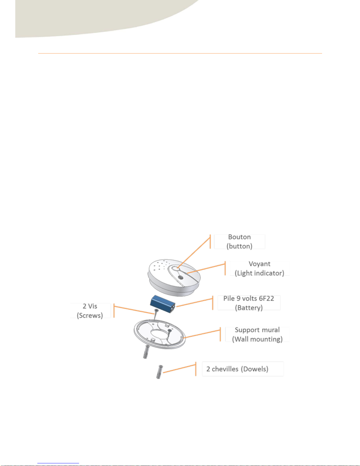
The product is as follows:
Figure 1 : Exploded View Product
Page 8
User Manual : ZGAS
CLEODE
page 8 sur 21
I.2 Meaning of the Light indicator
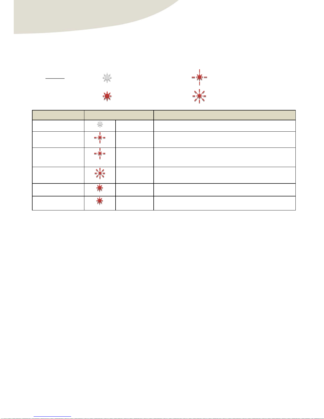
The red light allows viewing of sensor’s status and the presence of smoke or carbon monoxide.
This indicator takes the following states according to procedures describes in the table below:
Mode
State
Description
De fa ult
Wi thout separate announcement, the association remains off.
Sta rt-up 2 time s
At s ta rtup, the sensor flashes twice slowly.
Ide ntification
The ti me is gi ven
in the frame
Ide ntify
On rece iving identify command, the sensor blink slowly as the
ide ntification time isn’t exceeded.
Manual start of the
association phase
Up to 20 s e conds
The device blinks slowly when he researches a coordinator.
Pairing OK
2 s econ ds
Once associated, the sensor turns on 2 seconds.
Smo ke alarm or carbon
monoxide alarm
continue s
If the sensor detects the smoke o r an abnormal level of carbon monoxide,
the red light turns on until the end of the alarm.
I.3 Specifications
Stack ZigBee™
ZigBee™ Pro 2007 Can operate on all 16 channels ZigBee
Radio range
30 m (inside)
Smoke detector
1% ~ 5% PI OBS
CO detector
100 ±50ppm
Temperature of use
5 to +40 °C
Sound
85 dB à 3m
Power
1 battery 9V 6F22
Battery Life
~ 1 year
Dimensions
Ø110mm – height 37mm
Turn off
Turn on during 2s
Slow flashing
Fast flashing
Legend :
Page 9

User Manual : ZGAS
CLEODE
page 9 sur 21
II. ‘Quick Start’
Procedure of quick start:
1) Install the product (for details see section III.1)
2) Pairing the product ZGAS in the ZigBee® network (for details see section III.4)
3) The product is operational in your ZigBee® network.
4) Test the sensor (for details see section III.3)
Page 10
User Manual : ZGAS
CLEODE
page 10 sur 21
III. Procedures
III.1 Installation
IMPORTANT: This product should be mounted on a wall or ceili ng.
III.1.1 Recommendation positioning
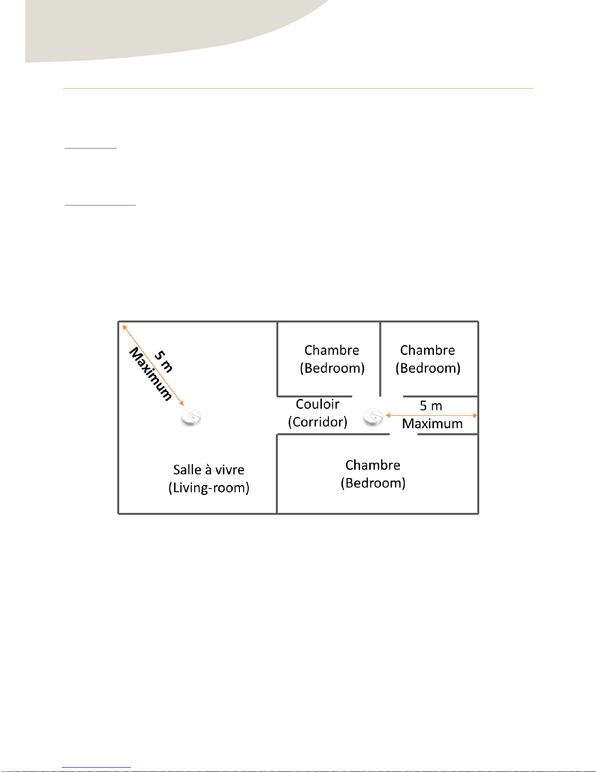
Where to install:
For maximum protection, install a ZGas on each level of housing. The risk is greater at night, it is recommended to
place the sensors near bedrooms, see in the bedroom.
The ZGas can cover an area of about 50 m² of space without partitioning. For optimum functionality, the sensor
mustn’t be placed more than 5m from the farthest extremity of the room.
In the case of a hallway measuring more than 10 m long it is advisable to install two sensors with less than 10 m
them.
Figure 2 : Positioning on a level
Page 11
User Manual : ZGAS
CLEODE
page 11 sur 21
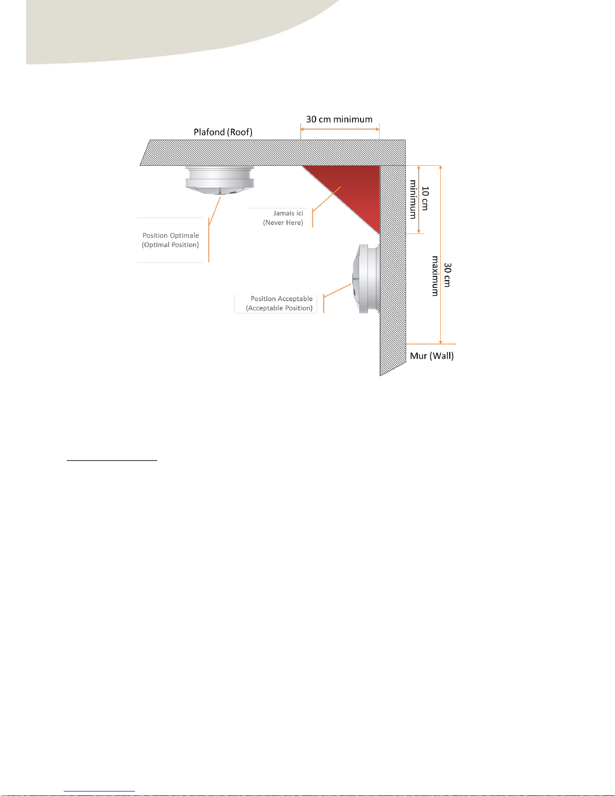
Prefer a ceiling installation for residential construction. Then position the product ZGAS at least 30cm from a wall.
For installation on a wall: position the product at least 10 cm of a wall/ceiling and up to 30cm below the ceiling
(see diagram below).
Figure 3 : Clearances when positioning
If you want to integrate the ZGas in a ZigBee® network, make sure it is installed in the area of network coverage
and the audible alarm can be heard from every bedroom with the door closed.
Where not to install:
Do not install outdoors.
Do not install in a garage.
Do not install near a heat source (oven, grill, hob …)
Do not install within 1 m around the following points:
Heating vent or air conditioning.
Fan
Or others elements with high air flow.
Do not install in the wet room (shower, bath …)
Do not install behind curtains or other objects that may block the sensors.
Do not install near a light source.
Do not install areas where the temperature is below 5 °C or greater than 40 °C.
Avoid excessively dusty, dirty or greasy that may damage the sensors.
Prefer areas away from doors and windows that open outward.
Page 12
User Manual : ZGAS
CLEODE
page 12 sur 21
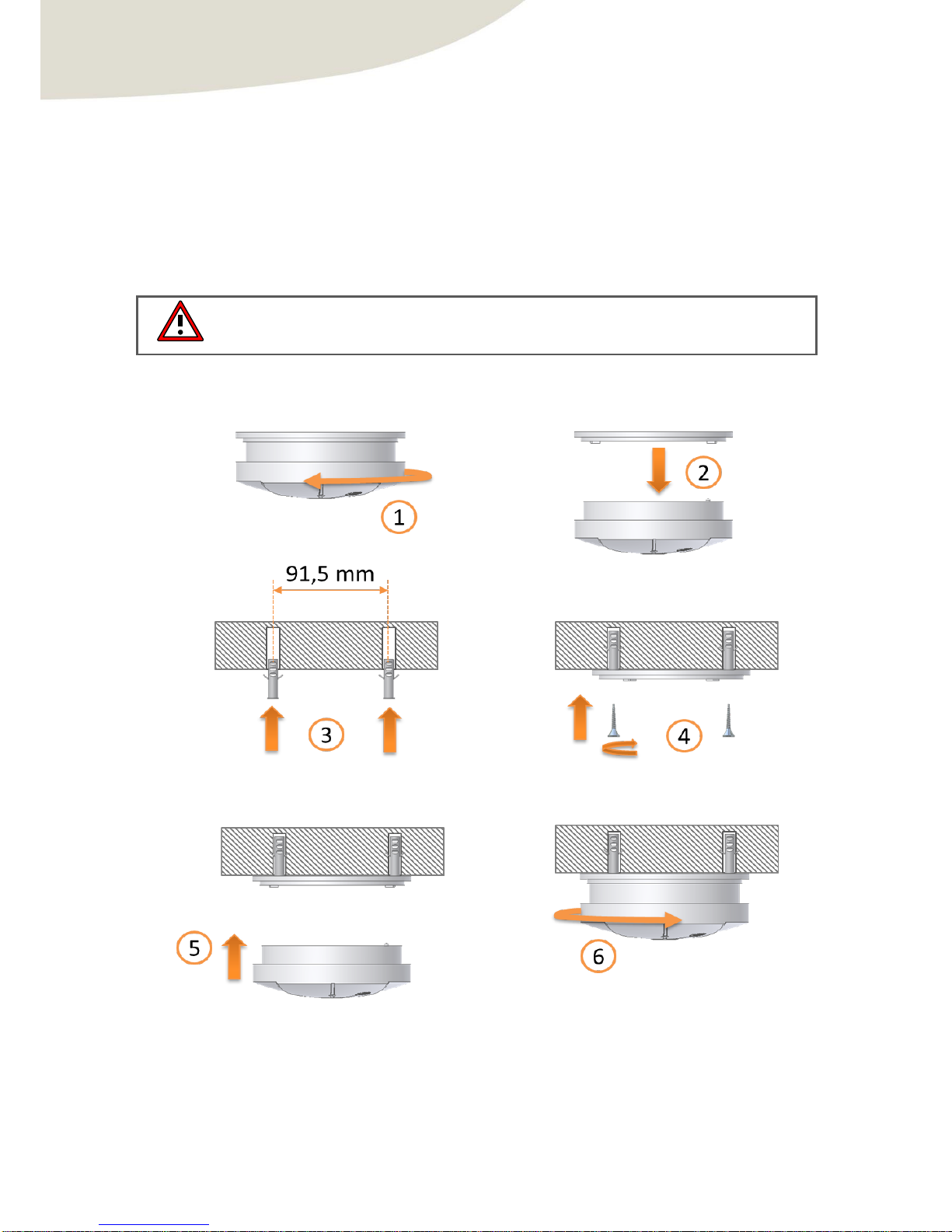
III.1.2 Instructions to mount
1) Unlock ZGas of its socket by turning it clockwise.
2) Remove ZGas from its socket.
3) Select the correct location for your detector (see §III.1.1), drill two holes Ø5.0mm in the ceiling (use the
wall mounting as a template) and insert two plastic dowels in the holes.
4) Fix the socket to the ceiling using the screws supplied.
5) Insert and connect a new battery in the battery holder. Fix the product to the mounting socket by aligning
the locking tabs.
Warning :
The detector can’t be placed on its support without battery in the slot.
6) Turn clockwise to lock.
Figure 4 : Mounting of ZGas
Page 13
User Manual : ZGAS
CLEODE
page 13 sur 21
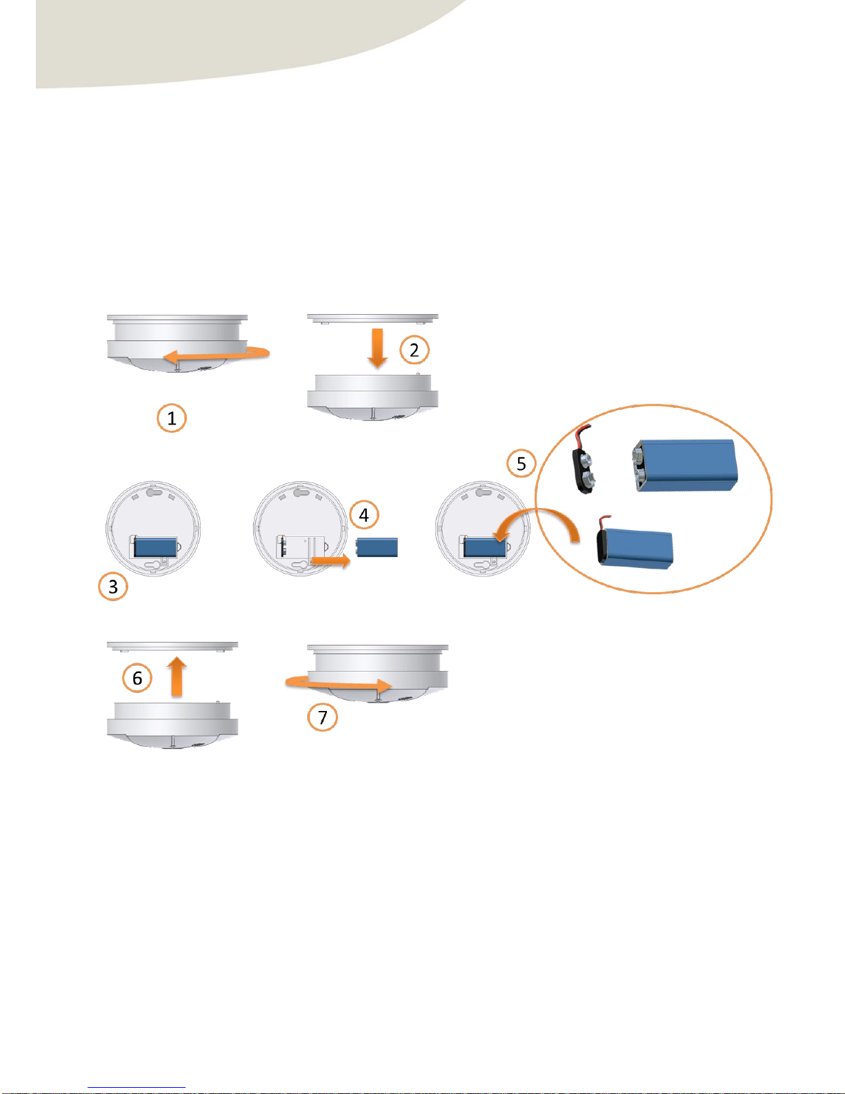
III.2Changing the batteries
To change the batteries of ZGas, proceed as follows:
1) Unlock ZGas of its socket by turning it clockwise.
2) Remove ZGas from its socket.
3) Return the ZGas.
4) Remove the old battery.
5) Put a new battery.
6) Fix the product to the mounting socket by aligning the locking tabs.
7) Turn clockwise to lock.
Figure 5 : Changing the battery
Page 14
User Manual : ZGAS
CLEODE
page 14 sur 21
III.3 Maintenance
III.3.1 Check functionality
It is recommended to check the functionality of the sensor once a month, press the button once, the sensor
beeps and the LED turns on and turns off.
III.3.2 Maintenance
It is recommended to clean the sensor regularly to avoid obstruction of sensor:
Cleaned the sensor surface with a soft cloth.
Use a vacuum cleaner with a soft brush to remove dust that may accumulate at the openings of the case.
III.4 Pairing the product for the first time
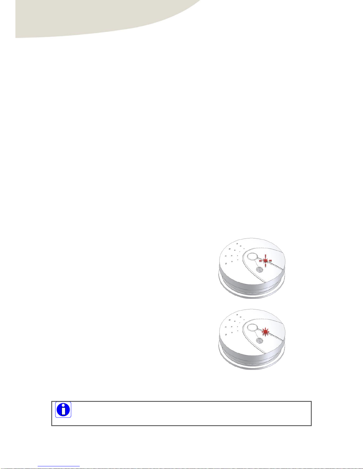
To pair the ZGas in a ZigBee® network, proceed as follows:
1) Allow the addition of ZigBee® object in your
network (see the manual of your ZigBee®
coordinator).
2) When the power is turned on, the ZGas trying
to join a network during few seconds and blink
twice.
3) If a coordinator is present and allows the ZGas
to join, the red light turns on for 2 seconds and
then turns off.
If the association isn’t possible, the ZGas will sleep, it will automatically attempt to join a
network after 15 minutes. This time will be doubled for each new association failure.
Page 15
User Manual : ZGAS
CLEODE
page 15 sur 21
III.5 Restart manually the pairing
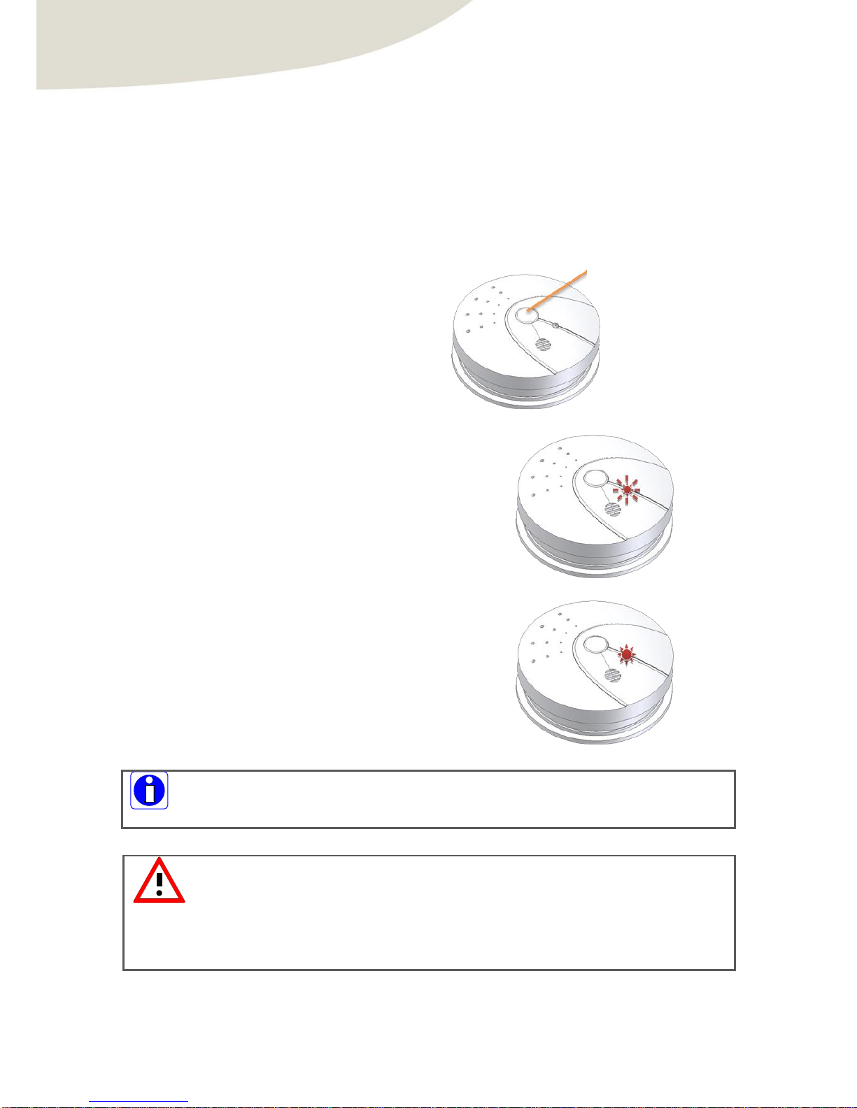
To pair the ZGas again in a ZigBee® network, proceed as follows:
1) Allow the addition of ZigBee® object in your
network (see the manual of your ZigBee®
coordinator)
2) Hold 3 seconds the pairing button.
3) If the ZGAS was not associated it will flash
rapidly during 20 seconds. The ZGAS is looking
for a coordinator during this flashing.
4) If the association is successful, the red light
turns on for 2 seconds and then turns off.
The ZGas saves network parameters automatically on which it is already connected.
It is therefore possible in a network change (or when the network coordinator has been
changed) that the product can’t fit on the new network.
In this case, it is necessary to clear the existing network settings by performing a reset
procedure (see paragraph below).
If the light is not flashing after performing a long press of 3 seconds, the ZGas is already
associated in a network.
Appui long 3s
(Push during 3s)
Page 16
User Manual : ZGAS
CLEODE
page 16 sur 21
III.6 Reset of network parameters of ZGas
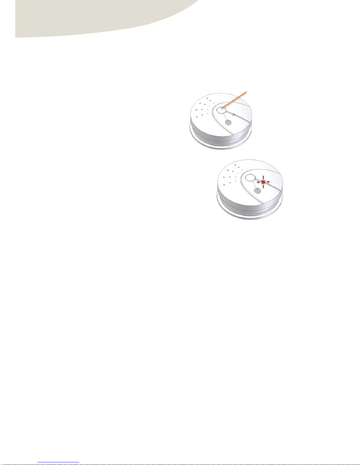
To clear the network parameters of ZGas, proceed as follows:
1) Press the pairing button during 5 seconds.
2) If the product ZGas reset, the red led blinks 2
times and turns off.
Appui long 5s
( Push during 5s )
Page 17
User Manual : ZGAS
CLEODE
page 17 sur 21
IV. Software interface
IV.1 Presentation
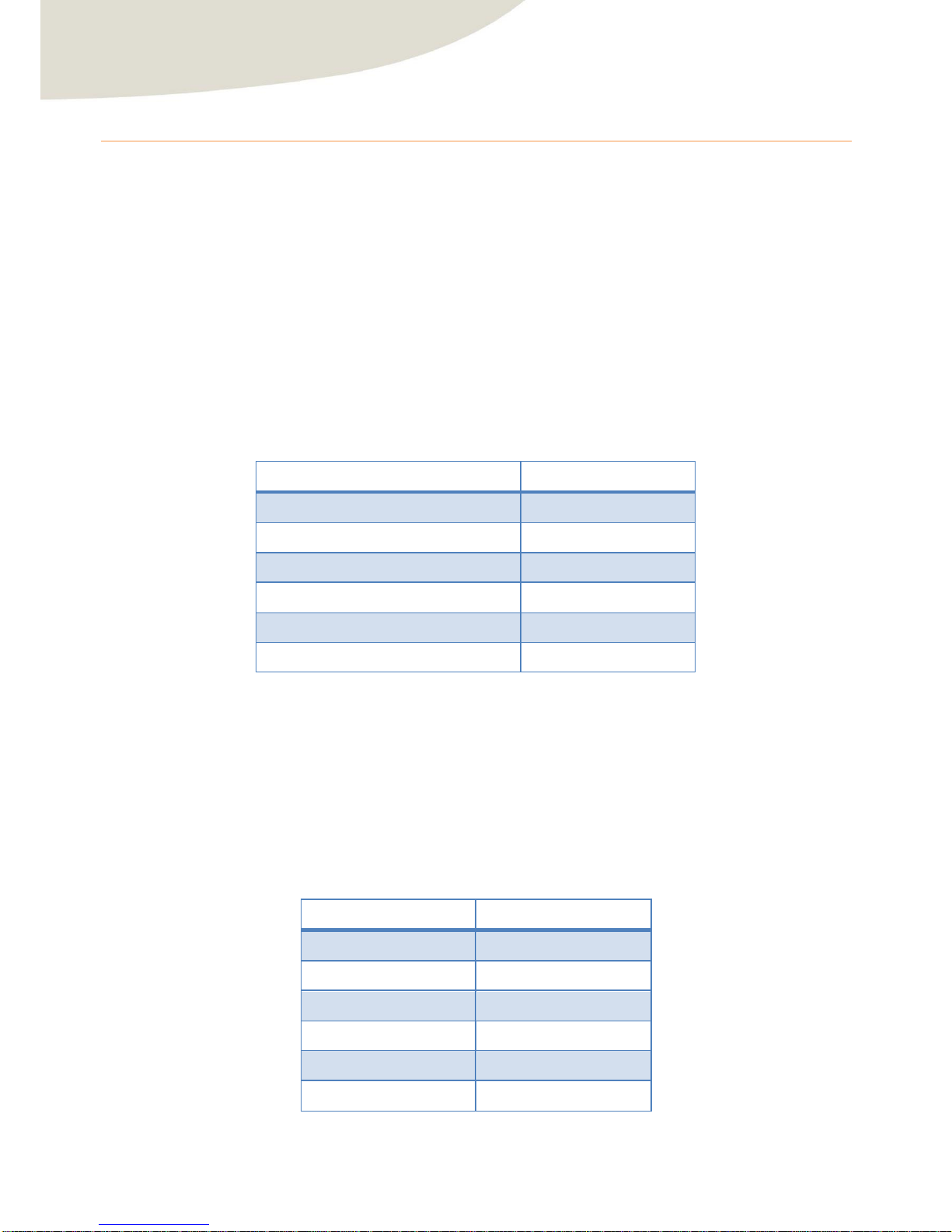
Le ZGas contains an application type IAS Zone denied in the standard Home Automation (See document [3]).
This is fully compliant with the ZigBee® Pro 2007 and Home Automation profile. For more details on the data
exchanged, please refer to the documents [1], [2] and [3].
IV.2 Application
IV.2.1 Description of the application
Device ID : IAS Zone
Endpoint : 1
Clusters :
Server
Client
Basic (0x00)
/
Power Configuration (0x01)
/
Identify (0x03)
/
Alarms (0x09)
/
IAS Zone (0x0500)
/
IAS Warning Device (0x502)
/
IV.2.2 Description of clusters
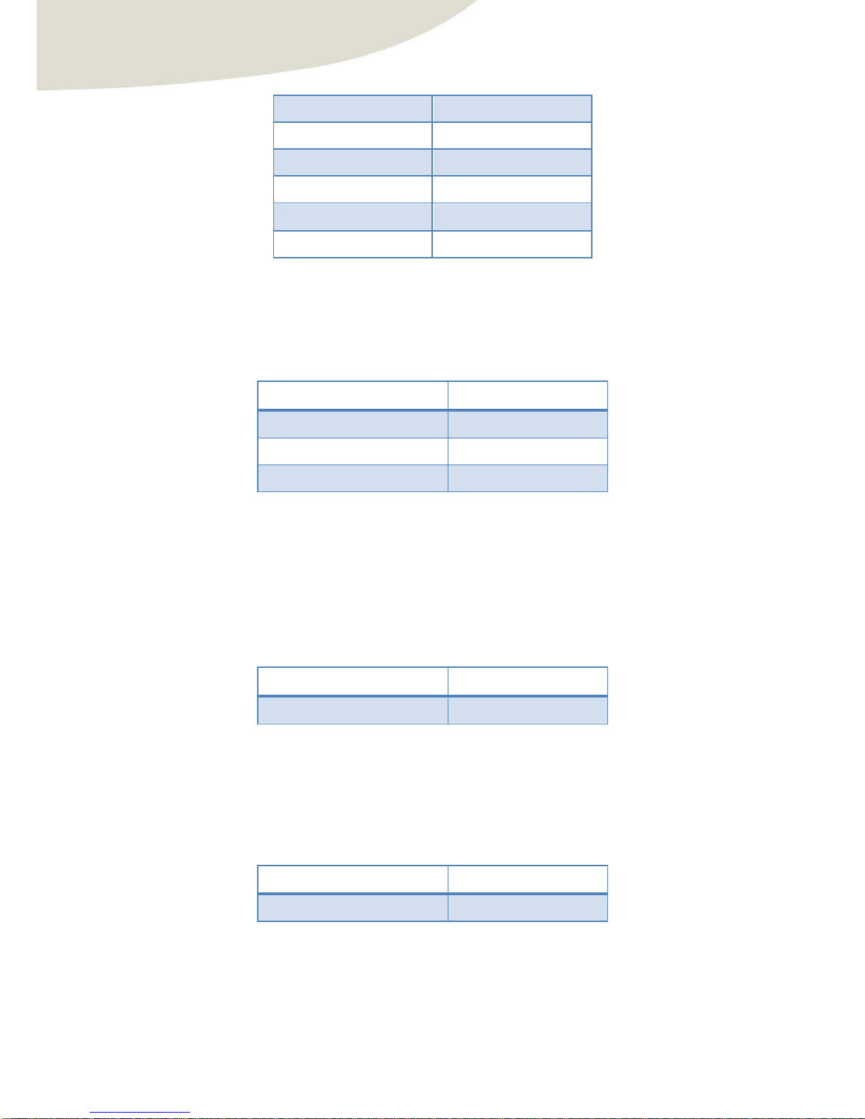
Here is a brief description of clusters and attributes implemented in the ZGas. For more details on the operation
of these, please refer to the document [1].
IV.2.2.1 Cluster Basic
This Cluster provides information of version, manufacturer, model, etc…
Attributes
Attributes identifier
ZCLVersion
0x0000
ApplicationVersion
0x0001
StackVersion
0x0002
HWVersion
0x0003
ManufacturerName
0x0004
ModelIdentfier
0x0005
Page 18
User Manual : ZGAS
CLEODE
page 18 sur 21
DateCode
0x0006
PowerSource
0x0007
LocationDescription
0x0010
PhysicalEnvironment
0x0011
DeviceEnabled
0x0012
AlarmMask
0x0013
IV.2.2.2 Cluster Power Configuration
This cluster is used to specify the level of low battery voltage threshold via the value of the attribute
BatteryVoltageMinThreshold.
Attributes
Attributes identifier
BatteryVoltage
0x0020
BAtteryAlarmMask
0x0035
BatteryVoltageMinThreshold
0x0002
The report of the battery voltage is available to monitor the battery.
IV.2.2.3 Cluster Identify
This cluster is used to identify the device in the network. By writing the value of the attribute IdentifyTime, the
red led of the device will flash during the time specified by this value.
Attributes
Attributes identifier
IdentifyTime
0x0000
IV.2.2.4 Cluster Alarms
This cluster is used to notify an alarm. For ZGas, the only alarm treated concerns the battery voltage. If the
voltage is too low (less than BatteryVoltageMinThreshold) the attribute AlarmCount change to 1 and an alarm
message is sent on the network.
Attributes
Attributes identifier
AlarmCount
0x0000
Page 19
User Manual : ZGAS
CLEODE
page 19 sur 21
IV.2.2.5 Cluster IAS Zone
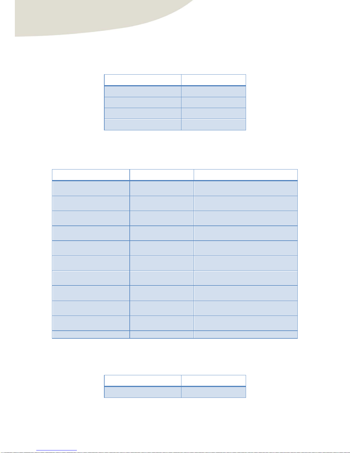
This cluster is used to report the value of the attribute ZoneStatus when the sensor has detected smoke or carbon
monoxide. Upon detection and end of detection, a command of type ZoneStatusChangeNotification is sent in the
network to indicate the new value of ZoneStatus.
Attributes
Attributes identifier
ZoneState
0x0000
ZoneType
0x0001
ZoneStatus
0x0002
IAS_CIE_Address
0x0010
The sensor performs an Enrolment request with the CIE (Control and Indicating Equipment) automatically after
writing the IEEE address of CIE in the attribute IAS_CIE_Address.
The ZoneStatus attribute is a bitmap. The description of each bit is shown in the following table:
Bit
Description
Values
0
Monoxide Alarm
1 – Alarmed
0 – Not Alarmed
1
Smoke Alarm
1 – Alarmed
0 – Not Alarmed
2
Tamper
1 – Tampered
0 – Not Tampered
3
Battery
1 – Low battery
0 – Battery OK
4
Supervision reports
1 – Reports
0 – Does not reports
5
Restore reports
1 – Reports restore
0 – Does not reports restore
6
Trouble
1 – Trouble/failure
0 – OK
7
AC (mains)
1 – AC/Mains fault
0 – AC/Mains OK
8
Test
1 – Sensor is in test mode
0 – Sensor is in operation mode
9
Battery defect
1 – Sensor detects a defective battery
0 – Sensor battery is functioning battery
10-15
Reserved
Reserved
IV.2.2.6 Cluster Warning Device
This cluster is used to start a fire sound at the request of CIE of the time defined in the attributes MaxDuration.
Attributes
Attributes identifier
MaxDuration
0x0000
Page 20

User Manual : ZGAS
CLEODE
page 20 sur 21
Repair and maintenance
Defective equipment shall be first reported to the CLEODE support team in order to be assigned an RMA number.
Be prepared to state your name, company and the serial number of the defective item to the support personnel.
The item shall then be returned to CLEODE with the following documents:
The RMA number
A copy of the delivery slip
A detailed description of the default and the test context
The maintenance period is typically four (4) weeks starting from the date of reception of the equipment at the
CLEODE headquarters.
Page 21
User manual : ZGAS
CLEODE
page 21 sur 21
All technical requests should be sent to the following address or by email to:
CLEODE S.A.
Technical and Maintenance Service
3 rue Thomas Edison
22300 Lannion
FRANCE
Phone: +33 (0) 2 96 48 68 18
Fax: +33 (0) 2 96 48 19 11
Email: [email protected]
Web: http://www.cleode.com
End of User Manual
 Loading...