

Page 1 of 26
Clenergy SPH Installation and Operation Manual
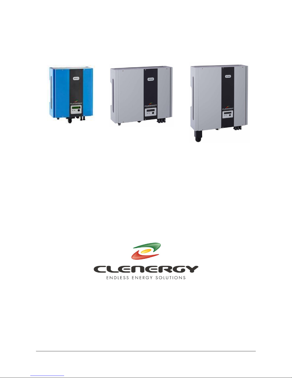
SPH Grid PV-inverter
Installation and Operation Manual
SPH MODELS
INCLUDED IN THIS MANUAL
SPH15 1500W
SPH20 2000W
SPH30 3000W
SPH40 4000W
SPH60 6000W
N305 WeiYe Building, Pioneer Park XiaMen China 361006
Tel: +86-592-5781288
Fax: +86-592-5782298
Website: www.clenergy.com.cn

Page 2 of 26
Clenergy SPH Installation and Operation Manual
Important Safety Information
Warning - Risk of Electric Shock
Failure to comply with these warnings and instructions can result in
damage to property, risk of fire, serious injury or death.
Do not remove the covers. The unit contains no user serviceable parts.
Hazardous voltage is present inside the unit from both DC and AC sources.
Hazardous voltage remains inside the unit even when disconnected.
The photovoltaic (PV) array supplies hazardous voltage when exposed to
light, even at very low intensity. Even ungrounded photovoltaic arrays
present an electric shock hazard through ground capacitance.
The unit is designed to supply power to the electric grid (AC utility) only. It
must not be connected to other AC electric generators or power supplies.
This may cause permanent damage to the unit and/or AC power supply.
The earth connection of the electric grid (AC utility) to the inverter should be
firm and visible.
Connection to the electric grid (AC utility) typically requires a permit or
interconnection agreement with the electricity provider. Contact your
electricity provider for more information.
All local and national codes and regulations for installation, wiring and
inspection of electrical equipment must be complied with.
Installation and troubleshooting of this unit must only be performed by
properly trained electricians or installation technicians, qualified to install or
service PV inverters.
Incorrect installation, troubleshooting by unqualified persons or modification
of the electrical wiring poses a safety risk to the installers, home/facility
occupiers and other users/operators of the electric grid (AC utility).

Page 3 of 26
Clenergy SPH Installation and Operation Manual
Both AC and DC voltage sources are terminated inside this equipment. The
unit must not be opened until both AC and DC circuits have been individually
disconnected for at least 3 hours. (Due to risk of electric shock from energy
stored in capacitors.)
Please take out the unit from the packaging box carefully. Check if there is
any obvious damage. Do not install the unit, if it is damaged. Please contact
your local dealer for a replacement.
The SPH inverter is the latest transformer less design. Please check the
requirements for your country regarding earthing regulations.

Page 4 of 26
Clenergy SPH Installation and Operation Manual
Before you start…
Thank you for purchasing the SPH Grid PV-Inverter. This is a highly reliable
product due to innovative design and precise quality control. When installed and
operated correctly, it will give many years of trouble free operation.
This manual contains important information for the safe and effective
installation and operation of the SPH Grid PV-Inverter. Be sure to read this
manual carefully before using the product.
If you encounter any problem during the installation or operation of the unit,
please check this manual first before contacting your local dealer or
representative. Most of the problems you may encounter can be solved by
following the instructions inside the manual.
Please keep this manual in a safe place for later use.
Page 5 of 26
Clenergy SPH Installation and Operation Manual
1. SPH inverter overview and connections
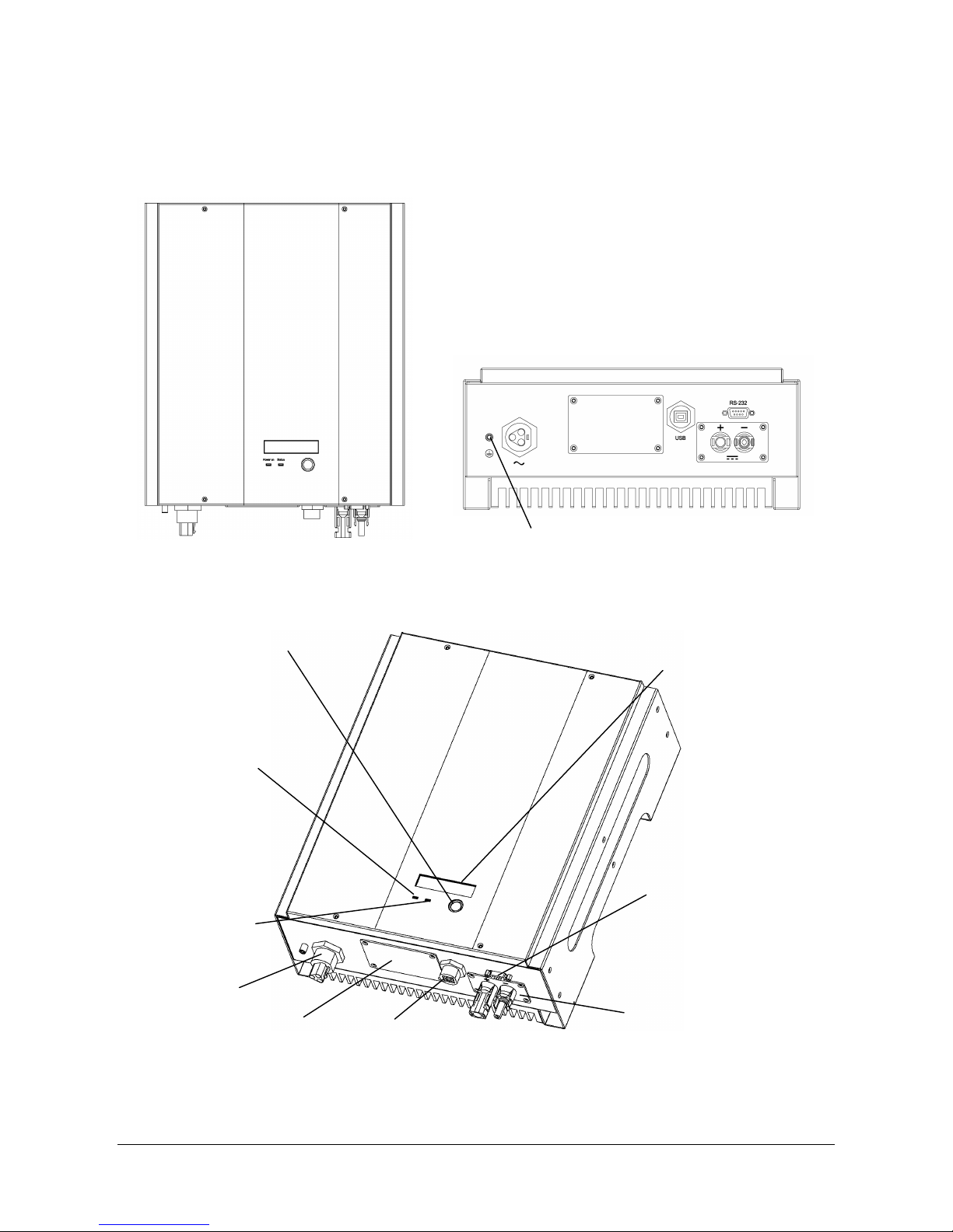
1.1. SPH15, SPH20 & SPH30
Front view Bottom view
External protective earth (PE)-terminal
Display and connections
LCD Display: Showing the
inverter status
RS232
Solar panel input
(DC)
Display information switch
Optional communication
slot: SNMP and RS485
USB
AC connector
Operation LED,
Blue, Working Mode
Operation LED, Red,
fault status
Page 6 of 26
Clenergy SPH Installation and Operation Manual
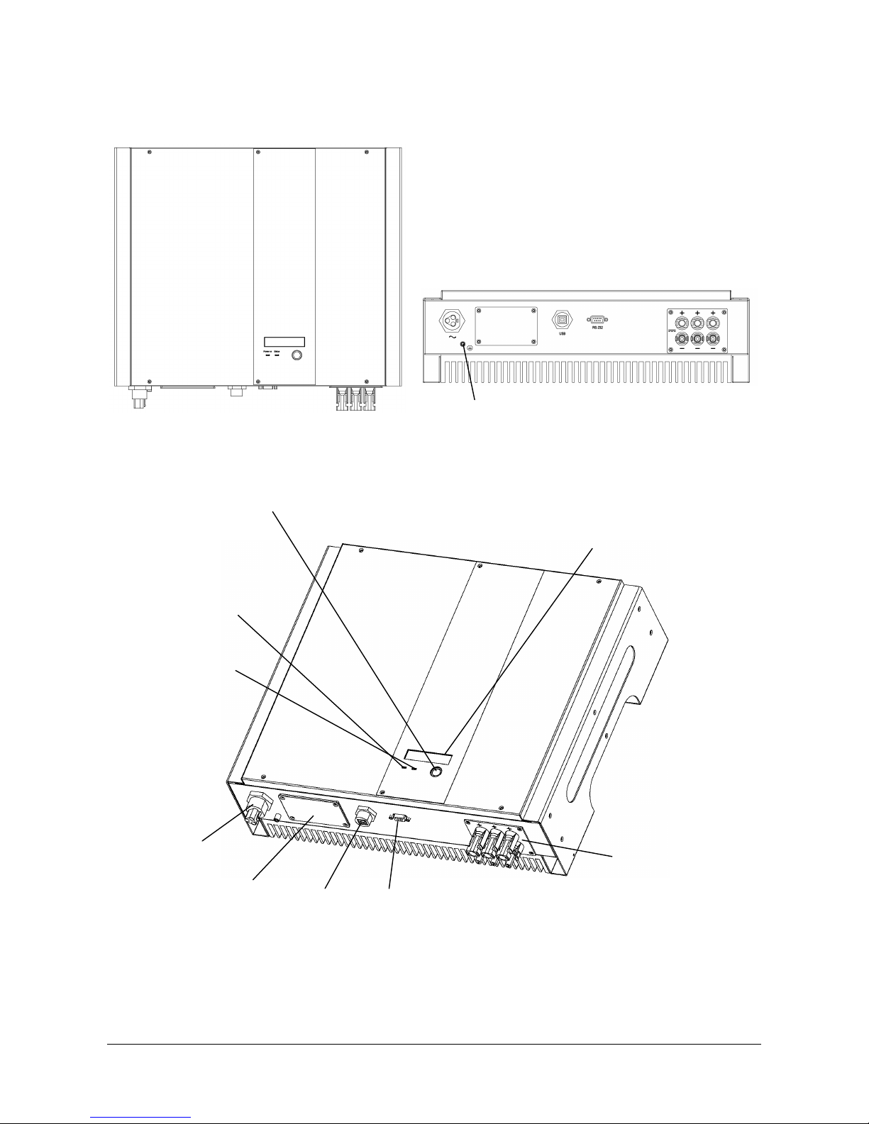
1.2. SPH40
Front view Bottom view
Display and connections
External protective earth (PE)-terminal
LCD Display: Showing the
inverter status
Display information switch
Operation LED,
Blue, Working Mode
Operation LED, Red,
fault status
AC connector
Optional communication
slot: SNMP and RS485
USB
RS232
Solar panel input
(DC)
Page 7 of 26
Clenergy SPH Installation and Operation Manual
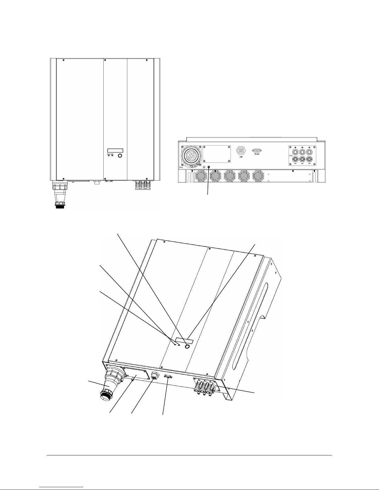
1.3. SPH60
Front view Bottom view
Display and connections
External protective earth (PE)-terminal
Display information switch
LCD Display: Showing the
inverter status
Operation LED,
Blue, Working Mode
Operation LED, Red,
fault status
AC connector
Optional communication
slot: SNMP and RS485
USB
RS232
Solar panel input
(DC)
Page 8 of 26
Clenergy SPH Installation and Operation Manual
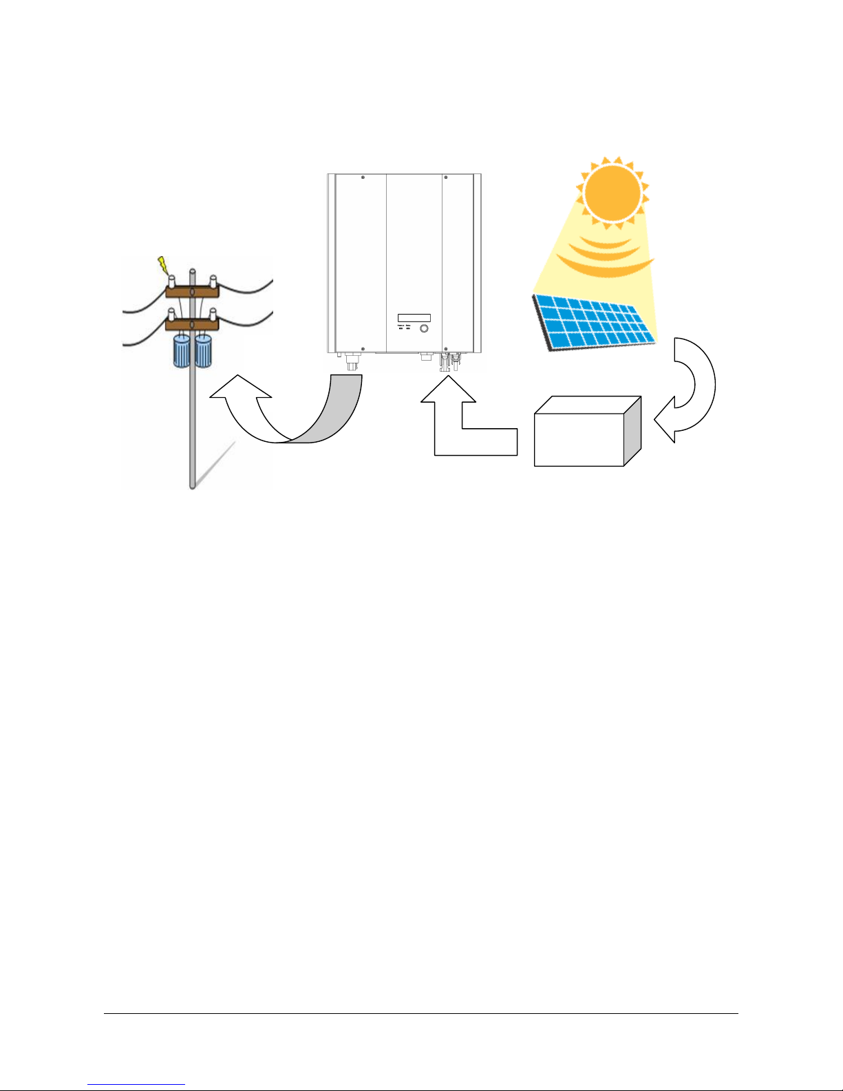
2. PV installation system diagram
PV array: Provides DC power to the SPH inverter. A DC
Disconnect Switch or optional Solar Concentrator is usually
fitted between the PV array and the SPH inverter.
SPH inverter: Converts DC power from the PV array into AC power. The AC
(Alternating Current) power is supplied to the electric grid (AC
utility). The SPH inverter uses Maximum Peak Power Tracking
(MPPT) to optimize the PV array operation and deliver
maximum power to the electric grid.
Connection: The “interface” between the SPH inverter and the
System Grid usually consists of an electrical breaker or fuse and
terminals for connection. It may also contain a disconnect
switch. For proper safety, this part must be designed by a
qualified electrician or electrical installation technician.
Utility: The electricity supply from the main electric grid
system must be single phase 220V to 250V, 50Hz
or 60Hz.
Connection System
SPH Inverter
Utility
PV Array
Disconnect
Switch

Page 9 of 26
Clenergy SPH Installation and Operation Manual
3. Installation
Before starting installation please check the following items:
This unit is suitable for indoor and outdoor usage. For best performance and
service life, outdoor installations should be sheltered from direct exposure to
rain and water.
The unit can operate with an ambient temperature of -25C to +55C. For
best performance and service life, the unit should be operated with an
ambient temperature of 0C to +40C. Above this temperature, the power
output may be reduced. It is recommended to shade the unit from direct
exposure to sunlight to prevent increased operating temperature.
The electric grid must be 220V to 250V, 50Hz or 60Hz single-phase.
Connection to electric grid must be approved by the electricity provider.
The installation must be done by a certified electrician.
The unit must be installed vertically in the orientation shown.
25cm Space
25cm Space

Page 10 of 26
Clenergy SPH Installation and Operation Manual
Step1: Mount SPH inverter to the wall or other vertical
surface
1. Select a solid wall or vertical surface to mount the unit. The mounting
surface must have sufficient strength to carry the weight of the unit (Given
in the specification). In areas of seismic activity, additional support or
restraint may be necessary. It is recommended that the inverter is installed
at a height that provides comfortable viewing and operation of the display
and controls.
2. There must be at least 25cm clear space above and below the unit. This is
to allow for proper air circulation and convection cooling.
3. Mark the 4 mounting hole positions required using the mounting backplate
as a template.
SPH15
SPH20
SPH30
SPH40
SPH60
W (mm)
312
312
312
465
465
H (mm)
362
362
362
386
516
D (mm)
131
131
141
131
142
4. Select appropriate mounting hardware for the type of mounting surface and
drill mounting holes of the appropriate size.
5. Fix the mounting backplate to the mounting surface using the selected
hardware at each of the 4 mounting holes.
6. Fix four screws with spacer on the four corners of the mounting back plate.
7. Hang the inverter unit onto the mounting back plate and press down.

Page 11 of 26
Clenergy SPH Installation and Operation Manual
8. Attach the “fix screws” to the bottom sides of the unit to securely attach the
inverter to the mounting plate.
9. Check the unit is securely mounted. Try to lift up the inverter at the bottom
to test that it is firmly attached. If not, adjust the mounting as necessary.
CAUTION: The electrical installation of this unit must only be performed by
electricians or technicians, qualified to install solar PV inverters.
Screw for hanging the
Inverter unit onto the
Mounting backplate
Wall
Wall
2 x M3 x 16L Screw

Page 12 of 26
Clenergy SPH Installation and Operation Manual
Step2: Prepare the electric grid (AC utility) connection
1. Verify that the electric grid voltage is 220V to 250V AC single-phase at 50Hz
or 60Hz. This information is available from the electricity provider.
2. Ensure that the AC supply wire to the inverter is disconnected from the
electric grid. For example, the fuse is removed or the circuit breaker is open.
Verify with an AC voltmeter that there is no voltage between the Line and
neutral AC wire and between each AC wire and earth ground.
3. The table provided suggests minimum wire sizes for the AC cable. Ensure
the selected wire conforms to local and national wiring codes.
Model
(mm)
AWG no.
1500
1.29
16
2000
1.29
16
3000
1.72
14
4000
2.05
12
6000
2.85
8
4. For SPH15 SPH20 SPH30 SPH40, connect AC wires as follows:
Disassemble the AC output female socket.
Connect AC wires to connection socket as indicated:
Strip the wire sheath and conductor insulators the minimum amount
necessary to insert the wires into the connection pins.
Insert Line wire to L, Neutral wire to N and Ground wire to pin
Fully tighten the wire clamp screws in each connection pin.
Assemble the socket again. Insert the whole socket into the inverter.
Twist the coupling ring to receptacle on inverter. Make sure it is perfectly
matched and tightly fastened.
Female insert
with coupling ring
Shell
Pinch ring
Pressing
screw
AC wire
inserting
direction

Page 13 of 26
Clenergy SPH Installation and Operation Manual
5. For SPH60, connect AC wires as follows:
Disassemble the AC output female socket.
Connect AC wires to connection socket as indicated:
Strip the wire sheath and conductor insulators the minimum amount
necessary to insert the wires into the connection pins.
Insert Line wire to L, Neutral wire to N and Ground wire to pin
Fully tighten the wire clamp screws in each connection pin.
Assemble the socket again. Insert the whole socket into the inverter.
Twist the coupling ring to receptacle on inverter. Make sure it is perfectly
matched and tightly fastened.
Do not connect the AC power at this time
Step 3: Connect to the PV array (DC)
1. Make sure the maximum open circuit voltage (V
oc
) of each PV string is less
than 550V UNDER ANY CONDITION for SPH15, SPH20 & SPH40 and 600V
for SPH60.
2. Ensure that the DC supply wires to the inverter are disconnected from the
PV strings. We recommend that a disconnect switch or optional Solar
Concentrator with disconnect is fitted between the PV array and the inverter.
When making connections to the PV array outputs, the PV panels must be
completely covered with shade material and the outputs must be shorted
together and to earth ground. Always follow local and national codes and
regulations for installation work on PV panels.
3. Verify with a DC voltmeter that there is no voltage between the positive and
negative DC wires and between each DC wire and earth ground.
Female insert
with coupling ring
Pinch ring
AC wire
inserting
direction
Pressing
screw
Lock key 1
Lock key 2

Page 14 of 26
Clenergy SPH Installation and Operation Manual
4. Attach MC (Multi-contact or Tyco) solar type connectors to the PV array DC
positive and negative wires. Use red connectors for the positive DC wires
and black connectors for the negative DC wires
5. Connect PV array DC positive wire(s) to the positive (+) terminal(s) of the
inverter. Connect the PV array DC negative wire(s) to the negative (-)
terminal(s) of the inverter. Each DC terminal on the SPH inverter is rated for
a maximum of 20A DC current. Ensure that the maximum short circuit
current of each PV string does not exceed 20A DC.
SPH15, SPH20, SPH30 - 1 pair SPH40, SPH60 - 3pairs
When connecting the DC terminals, ensure that the polarity is
correct. Incorrect connection may permanently damage the unit!
Step 4: Test the installation
1. Remove any protective short circuits applied to the PV array output.
2. Remove any shade material from the PV panels and ensure that the PV
array is illuminated by sunshine.
3. Turn on the external DC switch (if fitted).
4. After connecting the DC
1
, the message sequence on the LCD display should
be “INV Waiting” → “No Utility” and the RED fault LED keeps on.
5. Fit any fuses removed from the AC supply. Close the AC breaker or switch
and apply AC power to the inverter.
6. Verify that the inverter starts to work after a short delay. (This may take a
few minutes to verify that the electric grid is stable.)
7. If inverter works normally, the LCD display panel will show “Working mode”
and power is delivered to the electric grid. If there are any problems refer to
the Troubleshooting section for possible resolutions.
8. The installation test is complete.
1
Do not connect the AC power at this stage

Page 15 of 26
Clenergy SPH Installation and Operation Manual
4. Inverter status
The SPH Inverter is designed to be user friendly. The status of the inverter can
be easily understood from the display panel.
Display information
LED lamps
There are 2 operating status LED lamps on the unit.
Power LED (Blue): Lit when the unit is working and
transferring power.
Dark when the unit is shutdown or in fault
mode.
Status LED (Red): Lit when the unit is in fault or failure mode.
(See the display panel for more details.)
Dark in normal or shutdown operation.
LCD display panel
o Normal operation
The display panel will show “Working Mode” during normal operation.
In “Working Mode”, press the display button to enter “Meter Mode”. In “Meter
Mode” the display panel shows operating information. Each time the display
button is pressed, the value changes to the next item:
O/P WATT =
PV VOLT =
PV CUR =
GRID VOLT =
GRID FREQ =
O/P CUR =
xxx KWH (O/P energy)
RATING= xx KW (PV Inverter Rating)
M CPU Ver. xxx (Firmware version of Mater CPU )
S CPU Ver. xxx (Firmware version of Slave CPU)
1) If the display panel button is untouched for over 5 seconds, the display
panel will return to “Working Mode”.

Page 16 of 26
Clenergy SPH Installation and Operation Manual
2) If the display panel button is pressed and held for over 5 seconds, the
display will “Freeze” (Lock) at the selected display screen.
3) The display screen “Freeze” (Lock) is released when the display button is
pressed again and held for over 5 seconds.
In “Working Mode”, press the display button and hold for over 5 seconds to
enter “Settings Mode”. The display panel will then show “Setting”. Each time
the display button is pressed, the setting changes to the next item:
Contrast setting > Press button for over 5 seconds to enter
Press button to select: Contrast 1 to Contrast 5
Then press button for over 5 seconds
LCD will show “Setting”, Contrast setting is OK.
Language setting > Press button over 5 seconds to enter
Press button to select: English or German.
Then press button for over 5 seconds
LCD will show “Setting”, Language setting is OK.
4) If the display panel button is untouched for over 5 seconds, the display
panel will return to “Working Mode”.

Page 17 of 26
Clenergy SPH Installation and Operation Manual
LCD Display Panel Setting
Press Display
button <5sec
LCD Normal
Working Mode
Yes
Press Display
button >5Sec
No
Meter Mode
Setting Mode
Press button to select: Contrast 1 to Contrast 5
Then press button for over 5 seconds
LCD will show “Setting”, Contrast setting is OK
Yes
No
O/P WATT =
PV VOLT =
PV CUR =
GRID VOLT =
GRID FREQ =
O/P CUR =
xxx KWH (O/P energy)
RATING= xx KW (PV Inverter Rating)
M CPU Ver. xxx (Firmware version of Mater CPU )
S CPU Ver. xxx (Firmware version of Slave CPU)
Display button is
untouched for >5
Yes
No
Display button is
touched for >5
Display Freeze (Lock)
No
Yes
Press Display
button >5 Sec
Language Setting
Contrast Setting
Press Display
button < 5 Sec
Press Display
button > 5 Sec
Contrast setting
Language Setting
Press button to select: English or German.
Then press button for over 5 seconds
LCD will show “Setting”, Language setting is OK.
Yes
Yes
Yes
Yes
No
No
No
Yes
N W M
N W M
N W M
N W M
N W M
N W M
S D
S D

Page 18 of 26
Clenergy SPH Installation and Operation Manual
Fault condition
The display panel will show the Error Message during fault conditions. The
table shows the full list of messages with an explanation of the fault. See the
Troubleshooting section for further information on fault resolution.
Error Message
Explanation
No Utility
Grid voltage is not detected
PV Over Voltage
PV voltage is too high
DC Bus High
Internal DC bus voltage is too high
DC Bus Low
Internal DC bus voltage is too low
Over Temperature
Internal temperature is too high
Grid Fault
Grid voltage or frequency is out of range
Device Fault
Internal fault with inverter circuits
Isolation Fault
PV panel ground isolation problem
Impedance Fault
Grid impedance fault (or grid disconnected)
Ground I Fault
Grid output ground leakage current too high
Relay Failure
Grid output relay failure
DC INJ High
Grid DC injection too high
Ref 2.5V Fault
2.5V reference voltage internal circuit fault
DC Sensor Fault
Grid DC current sensor internal fault
GFCI Fault
Ground Fault Current Interrupt fault
Sci Fault
Internal Master/Slave communication fault
Consistent Fault
Internal Master/Slave value mismatch fault
CPU Ver Mismatch
Internal Master/Slave firmware incompatible
EEPROM Fault
Internal non-volatile memory fault
Grid V Mismatch
Internal Master/Slave grid voltage
mismatch
Grid F Mismatch
Internal Master/Slave grid frequency
mismatch
Grid Z Mismatch
Internal Master/Slave grid impedance
mismatch
GFCI Mismatch
Internal Master/Slave ground fault value
mismatch
DC Curr Mismatch
Internal Master/Slave grid DC current
mismatch
Typical display panel messages
The table explains typical display panel messages that occur depending on
the SPH inverter operating status and display panel mode.

Page 19 of 26
Clenergy SPH Installation and Operation Manual
Operating conditions
Display
message
Description
Normal working status
Power off
No display
PV inverter is totally shutdown, PV
voltage <=90V.
Standby
INV Standby
90V< Input voltage < =100V.
Initialization & waiting
INV Waiting
PV input voltage range 100V to
150V during start-up. Inverter is
waiting for feeding to grid.
Check grid
Testing
When PV voltage> 150V, inverter is
checking grid conditions.
Normal operation, MPPT
Working Mode
Inverter is supplying power to grid.
Monitoring parameters
Grid output power
O/P
Watt=xxxxW
The grid output power in Watts.
Accumulated energy information
xxxxx KWh
Total energy which has been
supplied to the grid since the
inverter was installed.
Grid voltage
GRID
VOLT=xxx.xV
Grid (rms) voltage in Volts.
Grid frequency
GRID
FREQ=xx.xHz
Grid frequency in Hertz.
Grid output current
O/P
CUR=xx.xA
Grid (rms) current in Amps.
PV panel voltage
PV
VOLT=xxx.xV
PV panel DC voltage in Volts.
System fault
Isolation failure
Isolation Fault
Earth fault of the PV-panels or
failure of surge voltage protection.
GFCI
(Ground Fault Current
Interrupter) active
Ground I Fault
Current on the ground conductor is
too high.
Grid failure
Grid Fault
Grid measured data is beyond the
specification (voltage & frequency).
Abnormal Grid Impedance
Impedance
Fault
1. Grid impedance higher than limit.
2. Grid impedance change is faster
than limit.
No grid utility voltage
No Utility
1. Inverter is not connected to grid
2. Grid voltage is not present.
DC-Input voltage too high
PV Over
Voltage
DC-Input voltage is higher than the
maximum limit (500VDC).
Inverter failure
Master/Slave CPU Consistency
failure
Consistent
Fault or
Mismatch
The readings of 2 microprocessors
are not consistent. It is probably
caused by CPU and/or other circuit
malfunction.
Bus failure
DC Bus High
DC Bus Low
DC-Bus voltage too high or too low.
Device failure
Device Fault
The device is unable to return to
normal status.
Temperature too high
Over
The internal temperature is higher

Page 20 of 26
Clenergy SPH Installation and Operation Manual
Operating conditions
Display
message
Description
Temperature
than the permitted operating
range.
Firmware Update
Updating Master CPU firmware
Master Flash
The internal program is updating
Master CPU through RS232
interface.
Updating Slave CPU firmware
Slave Flash
The internal program is updating
Slave CPU through RS232
interface.

Page 21 of 26
Clenergy SPH Installation and Operation Manual
5. Communication interfaces
The SPH inverter is equipped with an RS232 and USB communication interface
as standard. A communication slot is also provided for advanced
communications options.
The status of the inverter can be monitored via the communications interfaces
using a PC with the monitoring software “Solar control”. The software is free.
The software will be downloaded from www.clenergy.com.au/download.php.
Download the “SPH - Monitoring Software V1.26” and install in your computer.
Installation and service technicians can also change the unit setting and
download new firmware via the RS232 interface using “PV_Reflash” software.
1. RS232: The SPH inverter is equipped with a 3-wire RS232 interface using a
DB9 socket. This is located under the RS232 cover on the bottom of the unit.
The table below defines the connector pin functions. N.C. means “No
Connection”.
Pin
Assignment Description
1
N.C.
2
TxD
3
RxD
4
N.C.
5
Common
6
N.C.
7
N.C.
8
N.C.
9
N.C.
2. Optional communication slot: This slot is a very powerful expansion slot. The
SPH unit can accept a special communication function card in this slot. There
are 2 kinds of cards available now. One is an RS485 card and the other is a
SNMP (Simple Network Management Protocol) card. In the future, other
cards may be developed. For detailed information, please refer to the
instruction manual of the individual card.

Page 22 of 26
Clenergy SPH Installation and Operation Manual
6. Troubleshooting
When installed and operated correctly, the SPH inverter will give many years of
trouble free operation. Sometimes fault messages will be displayed due to
abnormal conditions on the PV array or electric grid. These messages will clear
automatically and the unit will restart once the PV array voltage and electric
grid conditions return to the normal ranges. Occasionally you may experience a
fault message that does not clear automatically when the conditions return to
normal. This may be due to a problem with the overall PV installation, or an
internal fault of the SPH inverter.
If the inverter continues to show a fault message then you may perform the
visual inspection and procedure ONLY.
If you are a qualified solar inverter Maintenance technician you may be able to
perform other tests as below.
Do not remove the covers. Warning - Risk of Electric Shock. Please follow the
below instructions
Visual Inspection
1 Check the staus of the Inverter to AC utility connection switch or MCB
Off/On
2 Check the status of the Inverter to Solar panel connection switch or MCB
Off/On
3 Check the status of the RED LED on the Inverter Off/On
4 Check the status of the BLUE LED on the Inverter Off/On
5 Check the error message on the LCD display on the Inverter
6 Check the samrtmeter been insatlled
Failure Verification
1 Turn on the external DC switch
2 After connecting the DC , Check the message sequence on the LCD display
should be “INV Waiting” → “No Utility” and the RED fault LED keeps on.
3 Turn on AC switch or MCB to power on the inverter.
4 Verify that the inverter starts to work after a short delay. (This may take a
few minutes to verify that the electric grid is stable.)
5 If inverter works normally, the LCD display panel will show “Working mode”
and power is delivered to the electric grid. Otherwise the LCD display an error.

Page 23 of 26
Clenergy SPH Installation and Operation Manual
6 The failure verification test is complete.
Some common fault messages and resolutions are explained below. If the
resolution procedure does not resolve the problem, contact your equipment
installer or supplier for assistance. Actions shown in bold letters should only
be performed by a qualified electrician or electrical technician.
Fault
Display
Possible actions
System
fault
No Utility
1. No grid voltage. Check the grid voltage by
multi-meter.
2. Check grid connection, such as wire and connector to the
inverter.
3. Check breaker between inverter and grid; if it is tripped,
DO NOT CLOSE again, get an electrician to check the
wiring and inverter.
Grid Fault
1. Wait for grid power to return to normal. If the grid returns
to normal, the inverter will start again automatically
within 5 minutes.
2. Check the grid voltage and frequency by
multi-meter. Make sure grid voltage and frequency meet
the specifications.
3. Contact your inverter service representative to discuss
adjusting the operating range, if permitted by the
electricity provider.
Impedance
Fault
1. The grid impedance is higher than the permissible value.
2. Wait for grid power to return to normal. If the grid returns
to normal, inverter will start again automatically within 5
minutes.
3. Check the wires between inverter and grid. For high
impedance
Connections get an electrician to increase the wire size.
4. Contact your inverter service representative to discuss
adjusting
The operating range, if permitted by the electricity
provider.
Isolation
Fault
1. Check the impedance between PV (+) & PV (-) and
earth ground. The impedance must be larger than
8M. If the impedance is low a ground fault may exist in
the PV array or wiring. Contact your PV array service
provider or electrician.
2. If above actions do not fix the problem, the isolation
detection circuit may be faulty. Contact your inverter
service representative.
Ground I
Fault
1. This is caused by too high ground current.
2. Disconnect the inverter from the grid power. Check the
AC wiring and connectionsystem.
3. After the cause is cleared, reconnect the grid power.
Check the status of the inverter.
4. If above actions do not fix the problem, the GFCI circuit
may be faulty. Contact your inverter service
representative.

Page 24 of 26
Clenergy SPH Installation and Operation Manual
Fault
Display
Possible actions
Inverter
failure
Over
Temperature
1. The internal temperature is higher than specified normal
value.
2. Reduce the ambient temperature by shading or
ventilation improvements or move inverter to cooler
place.
3. If this is not effective, a temperature sensor may be
faulty. Contact your inverter service representative.
PV Over
Voltage
1. C
Check the PV open-circuit voltage. This should be
less than 500VDC.
2. I
If the PV voltage is much less than 500VDC (e.g.
<430V), measure the DCV by multi-meter, compare
the readings on meter and LCD.
If the readings differ by >5%, contact your inverter
service representative.
Device Fault
1. This is caused by an inverter malfunction.
2. Disconnect PV (+) or PV (-) from the input, start the unit
again.
3. If it does not work, contact your inverter service
representative.
Consistent or
Mismatch
Fault
1. This is caused by inconsistent values between the main
(master) and redundant (slave) controllers of the inverter.
2. Disconnect PV (+) or PV (-) from the input, start the unit
again.
3. If this does not work, contact your inverter service
representative.

Page 25 of 26
Clenergy SPH Installation and Operation Manual
7. Specification
Model
SPH15
SPH20
SPH30
SPH40
SPH60
Output power
1500W
2000W
3000W
4000W
6000W
Maximum power
1650W
2200W
3300W
4400W
6000W
PV Input
Nominal DC voltage
360VDC
MPPT range
150 to 500VDC
150 to
600VDC
Working range
100 to 500VDC
100 to
600VDC
Max. PV Open-circuit Voltage
550VDC
600VDC
Max. input current
7.5ADC
10ADC
15ADC
20ADC
30ADC
Max. input power
1750W
2340W
3510W
4700W
6250W
Grid Output
Operational voltage
210VAC to 265VAC
Operational frequency
50Hz
Current distortion
< 3%
Power factor
> 0.99
The maximum
Grid Impedance Applicable
NA
NA
NA
NA
0.283Ω
(=0.24Ω +
j0.15Ω)
Conversion efficiency (max)
>94%
>95%
>95%
>96%
>96%
European efficiency
>93%
>94%
>94%
>95%
>95%
Environment
Protection degree
IP65
Operation temperature
-25 to 55ºC
Humidity
0 to 95%, non-condensing
Heat Dissipation
Convection
Acoustic noise level
<40dB,A-weighted.
Communication & features
Comm. Interface
RS232 & USB standard, SNMP & RS485 optional
F/W upgrade
Yes, via RS232
Mechanical
WHD (mm)
312x362x131
312x362x131
312x362x141
465x386x131
465x516x142
Weight (kg)
14
14
14
22
27
The product’s specifications are subject to change without notice.

Page 26 of 26
Clenergy SPH Installation and Operation Manual
Clenergy China
N305 WeiYe Building, Pioneer Park
Xiamen, China, 361006
Tel: +86-592 -5781288
Fax :+86- 592- 5782298
www.clenergy.com.cn
Clenergy Europe
(including Italy , France and Germany)
An der Welle 4
60322 Frankfurt
Tel: +49 69 7593 - 8499
Fax: +49 69 7593 - 8200
www.clenergy-de.de
Clenergy Australia
(including the US and Pacific)
18/20 Duerdin St,
Clayton VIC 3168
Tel: +61 3 9017 6688
Fax: +61 3 9017 6668
www.clenergy.com.au
 Loading...