

Clenergy PV-ezRack ezShade Series Planning And Installation
PV-ezRack® ezShade™
Code-Compliant Planning and Installation V2.0
Complying with AS/NZS1170.2:2011 AMDT 2-2012

Introduction
1. Introduction
Clenergy PV-ezRack®ezShade™ is a preassembled ground mount system suitable
for large scale commercial and utility scale
installations. PV-ezRack®ezShade™ has
been developed to fit any PV module. The
innovative and patented T-Rails simplify and
improve the accuracy of the installation. Using
high quality engineered components PVezRack
installers, time and money when delivering
large scale projects.
Please review this manual thoroughly before
installing your PV-ezRack®ezShade™system.
This manual provides
1) Simple introduction of the installation relating
to PV-ezRack®ezShade™ Mounting systems.
2) Planning and installation instructions for PVezRack®ezShade™.
PV-ezRack®ezShade™parts, when installed in
accordance with this guide, will be structurally
sound and meet the AS/ NZS 1170.2:2011
(R2016) standards. During installation and
especially when working on the roof, please
comply with the appropriate safety regulations,
and please also comply with the relevant
regulations of your local region.
®
ezShade™ saves developers and
Please check that you are using the current
version of the Installation Manual by contacting
Clenergy Australia by email on tech@ clenergy.
com.au, or your local representative.
The installer is solely responsible for:
• Complying with all applicable local or national
building codes, including any that may
supersede this manual;
• Ensuring that PV-ezRack and other products
are appropriate for the particular installation
and the installation environment;
• Using only PV-ezRack parts and installer
supplied parts as specified by PV-ezRack
(substitution of parts may void the warranty
and invalidate the letter of certification on
page 2);
• Recycling: Recycle according to the local
relative statute.
• Removal: Reverse installation process.
• Ensure that there are no less than two
professionals working on panel installation.
• Ensure the installation of all electrical
equipment is performed by licensed
electricians.
List of Contents
Introduction
Planning
Tools &Components
System Overview
Installation Instruction
Installation Guide_PV-ezRack_ezShade_AU_V1.0
1/10 Duerdin Street, Clayton VIC 3168 Australia
Tel: +61 3 9239 8088 Fax: +61 3 9239 8024
E-mail: sales@clenergy.com.au www.clenergy.com.au
01
02
05
07
10
• Ensuring safe installation of all electrical
aspects of the PV array. This includes providing
adequate earth bonding of the PV array and
PV-ezRack
required in AS/NZS 5033-2014 AMDT 2 2-20 .
®
ezShade™ components as
01page of 25
Planning
2. Planning
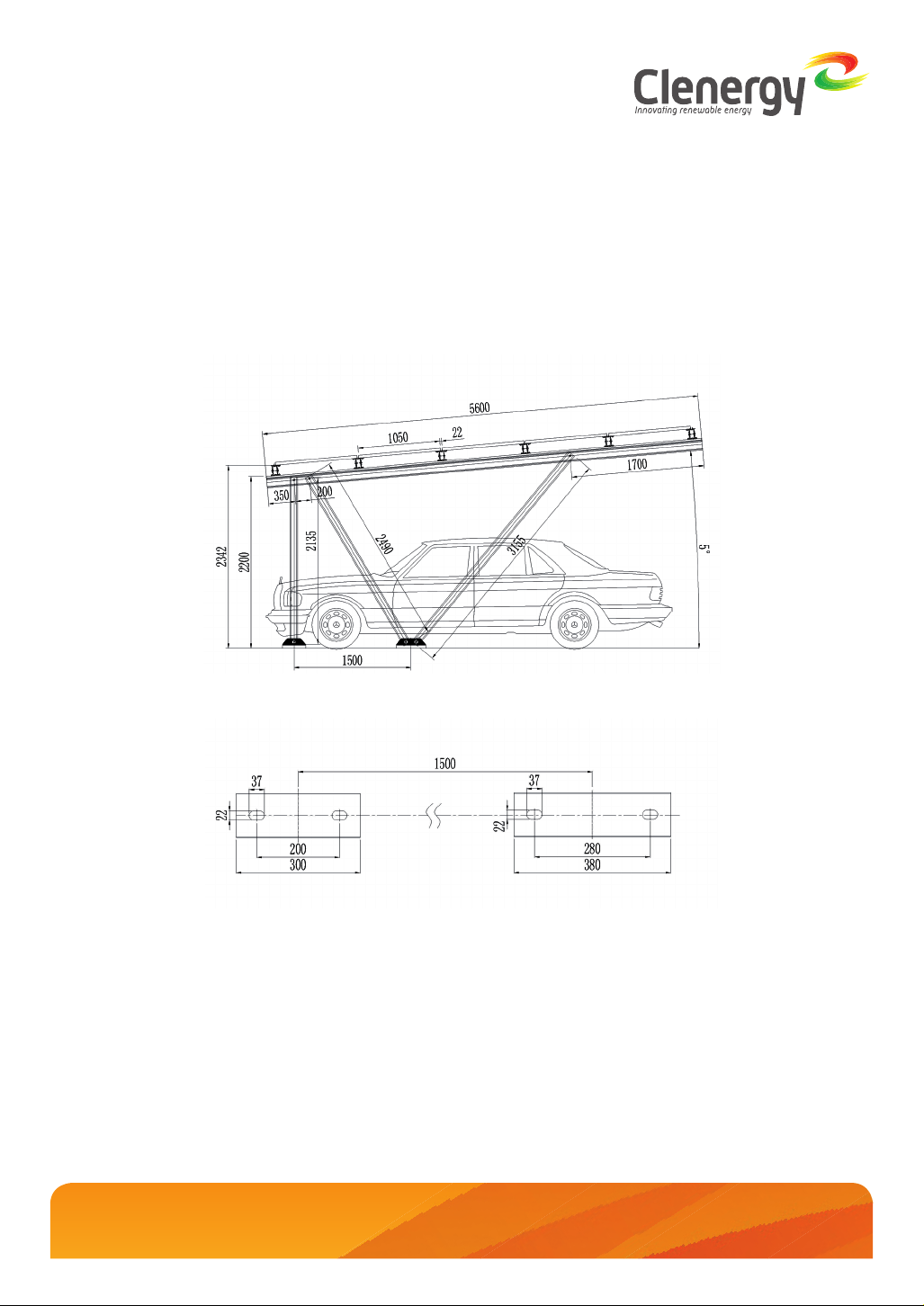
- Side View
Below are the side view drawings of support for 60 cell panels (up to 1700 x 1050 mm) and 72 cell panels (up
to 2108 x 1050 mm) at 5° tilt angle.
Installation Guide_PV-ezRack_ezShade_AU_V1.0
1/10 Duerdin Street, Clayton VIC 3168 Australia
Tel: +61 3 9239 8088 Fax: +61 3 9239 8024
E-mail: sales@clenergy.com.au www.clenergy.com.au
Location Plan of Anchors
02page of 25
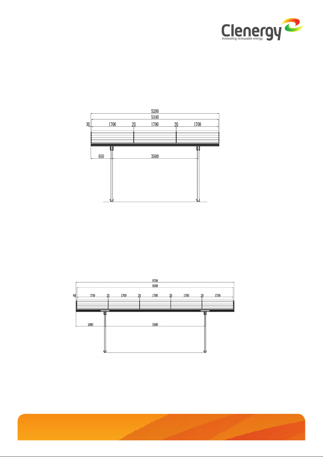
Planning
- Front View
Below are the front view drawings of support for 60 cell panels (up to 1700 x 1050 mm) and 72 cell panels (up
to 2108 x 1050 mm)
Front view drawings of single bay for 60 cell panels
Front view drawings of double bay for 60 cell panels
Installation Guide_PV-ezRack_ezShade_AU_V1.0
(up to 1700x1050 mm)
(up to 1700x1050 mm)
03page of 25
1/10 Duerdin Street, Clayton VIC 3168 Australia
Tel: +61 3 9239 8088 Fax: +61 3 9239 8024
E-mail: sales@clenergy.com.au www.clenergy.com.au

Planning
Front view drawings of single bay for 72 cell panels
(up to 2108x1050 mm)
Front view drawings of double bay for 72 cell panels
(up to 2108x1050 mm)
NOTE: 20 mm gaps between panels are for dry bars. If not using dry bars, it is not necessary to leave 20
mm gaps. .
Installation Guide_PV-ezRack_ezShade_AU_V1.0
1/10 Duerdin Street, Clayton VIC 3168 Australia
Tel: +61 3 9239 8088 Fax: +61 3 9239 8024
E-mail: sales@clenergy.com.au www.clenergy.com.au
04page of 25

Tools & Components
3. Tools and Components
3.1 Installation Tools
(M8
Hexagon
Socket
Screw)
String
Rubber hammer
Mark Pen
Scissor
Electric Drill
(ST4.8x16
self-tapping
screw & M8
Hexagon
Socket
Screw)
Wrench
Caulking Gun
Socket Wrench
M8/M12
Torque WrenchTapeAllen Key 6mm
Total Station or
Equivalent Instrument
Installation Guide_PV-ezRack_ezShade_AU_V1.0
1/10 Duerdin Street, Clayton VIC 3168 Australia
Tel: +61 3 9239 8088 Fax: +61 3 9239 8024
E-mail: sales@clenergy.com.au www.clenergy.com.au
05page of 25
Tools & Components
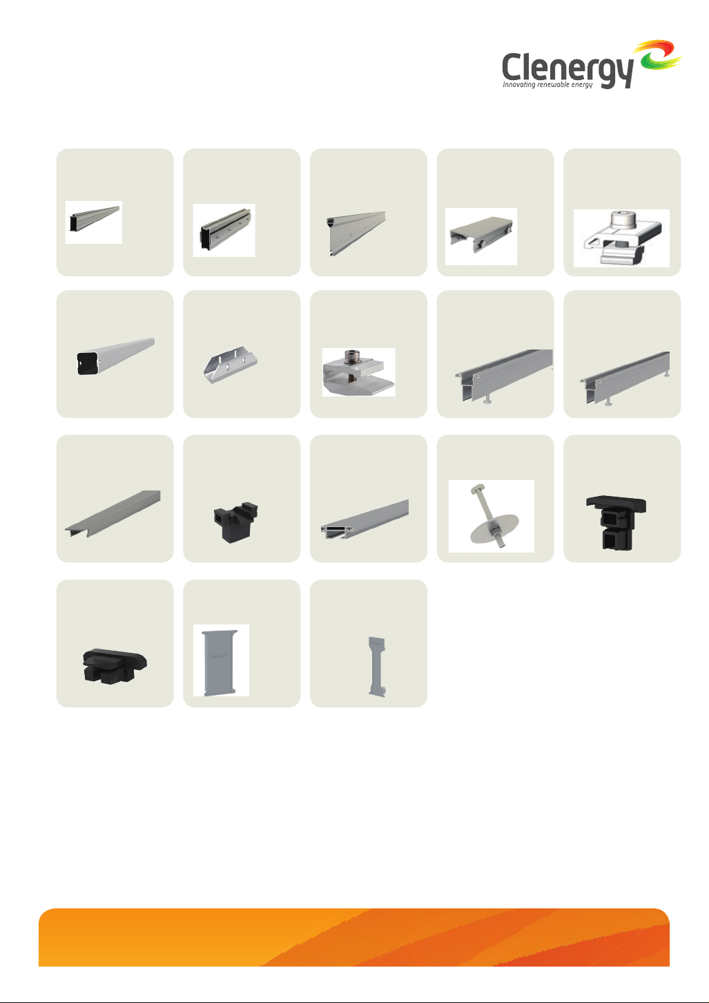
3.2 Components
ER-R-T150
T-Rail 150
RT-100/90
Rectangular Tube
ER-CAP-B/L
Top Cover for
Landscape Dry Bar
ER-SP-T150
Splice for T-150
Rail
U-AP/TR
Trapezoidal U-anchor
Plate 300/380
ER-CC-B/L
Cross Connection for
Dry Bar-Landscape
ER-B-150
Main Support
Beam
ER-MC-40
Module Clamp
40 mm
ER-B-P
Dry Bar-Portrait
ER-SP-B150
Splice for Main
Support Beam
ER-B-L/A
Dry Bar-Landscape
ER-B-T6/L
T bolt kit M6*L
ER-RC-T/G
Rail Clamp for T Rail
with Grounding
ER-B-L
Dry Bar-Landscape
(with Bushing)
ER-CAP-B/P
End Cap for Portrait
Dry Bar
ER-CAP-B/L
End Cap for
landscape Dry Bar
Installation Guide_PV-ezRack_ezShade_AU_V1.0
1/10 Duerdin Street, Clayton VIC 3168 Australia
Tel: +61 3 9239 8088 Fax: +61 3 9239 8024
E-mail: sales@clenergy.com.au www.clenergy.com.au
ER-CAP-T150/PA
Cap for T-150 Rail
ER-CAP-B150/PA
Cap for Composite
Beam
06page of 25
System Overview
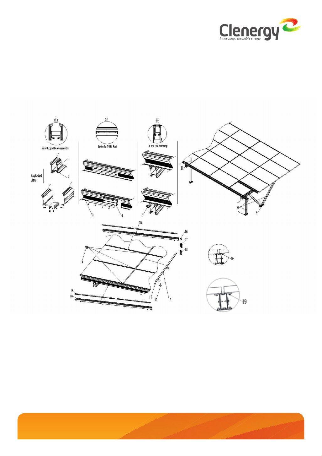
4. System Overview
4.1 Overview of PV-ezRack ezShade
Main Support Beam,150*L
①
Splice for Main Support Beam
②
T-Rail 150*L
③
Splice for T-150 Rail
④
Rail Clamp for T Rail
⑤
Rectangular Tube 100*90*L
⑥
Corrugated U-anchor Plate 300
⑦
Corrugated U-anchor Plate 380
⑧
Top Cover for Landscape Dry Bar
⑨
Dry Bar-Landscape(with Bushing)
⑩
Installation Guide_PV-ezRack_ezShade_AU_V1.0
1/10 Duerdin Street, Clayton VIC 3168 Australia
Tel: +61 3 9239 8088 Fax: +61 3 9239 8024
E-mail: sales@clenergy.com.au www.clenergy.com.au
07page of 25
 Loading...