

Page 1
CMS-4
IN-HELMET CARBON MONOXIDE MONITOR
O. M. 29872
DATE OF ISSUE: 07/2019
REVISION:
WARNING
Do not use this equipment
before READING this
© 2019 CLEMCO INDUSTRIES CORP.
One Cable Car Dr.
Washington, MO 63090
Phone (636) 239-4300
ax (800) 726-7559
F
Email: info@clemcoindustries.com
www.clemcoindustries.com
MANUAL and
UNDERSTANDING its
contents.
These WARNINGS are
included for the health
and safety of the operator
and those in the
immediate vicinity. Failure
to read and understand
these warnings can result
in injury or death.
Electronic files include a
preface containing the
same important
information as in the
orange cover.
Page 2
PREFACE
• Employers are responsible for identifying all job site hazards, educating and training all persons who will operate and
maintain these products, and ensuring that all blast operators and their assistants understand the warnings and
information contained in these instructions relating to safe and proper operation and maintenance of this equipment.
• Serious injury or death can result from failure to comply with all Occupational Safety and Health Administration
(OSHA)regulations and all manufacturer’s instructions.
• This equipment is not intended for use in any area considered hazardous per National Electric Code NFPA 70 2011,
Article 500.
• Read this document and follow all instructions before using this equipment.
OSHA regulations relating to ab rasi ve bla sting are con tained in the Code o f Federal Regulation s, Title 29 (29 C FR 1910 Gene ral Indust ry ;
1915 Maritime; 1926 Con s truction). The most pertinent include: 1910.94 Ventilation, 1910 .95 Occupational Noise Exposure , 1 910.132
Personal Protective Equipment, 1910.133 Eye and Face Prote cti on, 191 0.134 Respiratory Protection, 1910 .1 35 Head Protection,
1910.244 (b) Remote Controls. Consult www.osha.gov for complete information.
NOTICE
PRODUCTS AND THIS INFORMATIONAL MATERIAL
TO
PURCHASERS
AND USERS OF
OUR
Clemco proudly provides products for the abrasive blast
industry and is confident that industry professionals will use
their knowledge and expertise for the safe and efficient use of
these products.
The products described in this material, and the information
relating to these products, are intended for knowledgeable,
experienced users.
No representation is intended or made as to: the suitability of
the products described here for any purpose or application, or
to the efficiency, production rate, or useful life of these
products. All estimates regarding production rates or finishes
are the responsibility of the user and must be derived solely
from the user’s experience and expertise, not from information
contained in this material.
It is possible that the products described in this material may
be combined with other products by the user for purposes
determined solely by the user. No representations are
intended or made as to the suitability of or engineering
balance of or compliance with regulations or standard practice
of any such combination of products or components the user
may employ.
Abrasive blast equipment is only one component of an
abrasive blasting job. Other products, such as air
compressors, air filters and receivers, abrasives, scaffolding,
hydraulic work platforms or booms, equipment for lighting,
painting, ventilating, dehumidifying, parts handling, or
specialized respirators or other equipment, even if offered by
Clemco, may have been manufactured or supplied by others.
The information Clemco provides is intended to support the
products Clemco manufactures. Users must contact each
manufacturer and supplier of products used in the blast job for
warnings, information, training, and instruction relating to the
proper and safe use of their equipment.
GENERAL INSTRUCTIONS
This material describes some, but not all, of the major
requirements for safe and productive use of blast machines,
remote controls, respirator systems, and related accessories.
All equipment and accessories must be installed, tested,
operated and maintained only by trained, knowledgeable,
experienced users.
The blast operator and all workers in the vicinity must be
properly protected from all job site hazards including those
hazards generated by blasting.
Work environments involving abrasive blasting present
numerous hazards. Hazards relate to the blast process from
many sources that include, but are not limited to, dust
generated by blasting or from material present on the surface
being blasted. The hazards from toxic materials may include,
but are not limited to, silica, cyanide, arsenic, or other toxins
in the abrasives or in the coatings, such as lead or heavy
metals. Other hazards from toxins include, but are not limited
to, fumes from coating application, carbon monoxide from
engine exhaust, contaminated water, chemicals or asbestos.
In addition, physical hazards that may be present include, but
are not limited to, uneven work surfaces, poor visibility,
excessive noise, and electricity. Employers must identify all
job site hazards and protect workers in accordance with
OSHA regulations.
Never modify Clemco equipment or components or
substitute parts from other manufacturers for any Clemco
components or parts. Any unauthorized modification or
substitution of supplied-air respirator parts violates OSHA
regulations and voids the NIOSH approval.
IMPORTANT
Contact Clemco for free booklets:
Blast Off 2 – Guide to Safe, Productive, and Efficient Abrasive
Blasting, and Abrasive Blasting Safety Practices – Guide to Safe
Abrasive Blasting.
Clemco Industries Corp. One Cable Car Drive Washington MO 63090
Tel: 636 239-4300 — Fax: 800 726-7559
Email: info@clemcoindustries.com
Website: www.clemcoindustries.com
[I]
Page 3

PREFACE
OPERATIONAL INSTRUCTIONS
OSHA regulation 1910.134 requires appropriate respiratory protection for blast operators and workers in
the vicinity of blasting. These workers must wear properly-fitted, properly-maintained, NIOSH-approved,
respiratory protection that is suitable for the job site hazards. Blast respirators are to be worn only in
atmospheres not immediately dangerous to life or health from which wearers can escape without use of
the respirator.
The employer must develop and implement a written respiratory protection program with required
worksite- specific procedures and elements for required respirator use. The employer must provide
effective training to employees who are required to use respirators. The training must be comprehensive,
understandable, and recur annually, and more often if necessary.
NEVER use abrasives containing more than one percent crystalline silica. Fatal diseases, such as silicosis,
asbestosis, lead or other poisoning, can result from inhalation of toxic dusts, which include, but are not
limited to, crystalline silica, asbestos, and lead paint. Refer to NIOSH Alert 92-102; and OSHA CPL 03-00-007:
“National Emphasis Program – Crystalline Silica”, in which OSHA describes policies and procedures for
implementing a national emphasis program to identify and reduce or eliminate health hazards from exposure
to crystalline silica. Numerous topics associated with the hazards of crystalline silica in silica blasting sand
can be found on http:// osha.gov/. Clemco urges users of silica blasting sand to visit this website, and read
and heed the information it contains.
Always make sure the breathing air supply (respirator hose) is not connected to plant lines that supply
gases that include, but are not limited to, oxygen, nitrogen, acetylene, or other non-breathable gas. Never
modify or change respirator air line connections without first testing the content of the line for safe
breathing air. Failure to test the line may result in death to the respirator user.
• Breathing air quality must be at least Grade D,
as defined by the Compressed Gas Association
specification G-7.1, per OSHA Regulation 29 CFR
1910.134. When compressed air is the breathing air
source, a Clemco CPF (suitable sorbent bed filter)
should be used. Respirator hose connecting the
respirator to the filter must be NIOSH approved.
Non- approved hose can cause illness from
chemicals employed to manufacture the hose.
• All workers must always wear NIOSH-approved
respirators when any dust is present. Exposure to
dust can occur when handling or loading abrasive,
blasting, cleaning up abrasive, or working in the
vicinity of blasting. Before removing the respirator,
test the air with a monitoring device to ensure it is
safe to breathe.
For additional information, consult:
Occupational Safety and Health Administration (OSHA) - www.osha.gov
Compressed Gas Association (CGA) - www.cganet.com
The Society for Protective Coatings (SSPC) - www.sspc.org
National Association of Corrosion Engineers (NACE) - www.nace.org
American Society for Testing and Materials (ASTM) - www.astm.org
National Institute of Occupational Safety and Health (NIOSH) - www.niosh.gov
American National Standards Institute (ANSI) - www.ansi.org
OPERATOR SAFETY EQUIPMENT
• Clemco respirators DO NOT remove or protect against
carbon monoxide or any other toxic gas. Monitoring
devices must be used in conjunction with the respirator to
ensure safe breathing air. Always locate compressors and
ambient air pumps where contaminated air will not enter
the air intake.
• Always use Clemco lenses with Clemco respirators;
installing non-approved lenses voids the NIOSH approval.
Respirator lenses are designed to protect the wearer from
rebounding abrasive; they do not protect against flying
objects, heavy high-speed materials, glare, liquids, or
radiation.
INDUSTRY ORGANIZATIONS
[II]
Page 4

PREFACE
BLAST MACHINES AND REMOTE CONTROLS
OSHA regulation 1910.169 describes the necessity of pressure relief valves on compressed air equipment. Do not
operate blast machines with air compressors that are no t equipped with properly functioning pressure relief valves.
OSHA regulation 1910.244(b) requires the use of remote controls on blast mach ines.
Serious injury or death can result from many sources, among them:
Involuntary activation of the remote controls. Never modify or substitute remote control parts; parts are not
compatible among different manufacturers. Welding hose is not suitable for remote control hose. Its ID and material
composition make it unsafe for remote control use.
Exceeding the maximum working pressure. Clemco blast machines are built to ASME-code and carry a ‘U’ or ‘UM’
stamp, and National Board/serial number. Every machine is marked with its maximum working pressure. Never
exceed the maximum working pressure limits of the blast machine.
Uncontrolled blast stream. High-velocity abrasive particles will inflict serious injury. Always point the blast nozzle
in the direction of the blast surface only. Keep unprotected workers out of the blast area.
Welding on the blast machine. Never weld on the blast machine; welding voids the Nation al Bo ard approval and
may affect the dimensional integrity of the vessel.
Moving the blast machine. Never manually move a blast machine contain ing abrasive, any machine containing
abrasive must be moved with appropriate mechanical lifting equi pment.
HOSES, COUPLINGS, AND NOZZLE HOLDERS
The inside diameter (ID) of air hoses, fittings, and connections
should be at least four times larger than the nozzle orifice size. Blast
hose ID should be three to four times the size of the nozzle orifice.
Example: a #6 nozzle (3/8” diameter orifice) calls for 1-1/2” ID blast
hose and 1-1/2” ID or larger compressor hose. All hose runs should be
kept as short as possible and run in as straight a line as possible to
reduce pressure loss.
To install, squarely cut the end of the hose so that it fits snugly
against the coupling or hose end shoulder. Always use the screws
recommended by the manufacturer ensuring that they do not
penetrate the inner wall. Make sure the couplings tightly fit the hose.
Install cotter pins at ev ery conn ection or use couplings with built-in
lock-springs to prevent disengagement. Install safety cables at all
connections to prevent whipping if hoses disengage or blow out.
MAINTENANCE AND REPAIR
Completely read and follow all service instructions and recommended maintenance intervals. Always shut off compressor and
depressurize blast machine before performing any maintenance. At every service interval, clean all filters, screens, and alarm systems. If
spring-loaded abrasive valves are used, always cage spring before disassembly.
WARRANTY
The following is in lieu of all warranties, express, implied or statutory, and in no event shall seller or its agents, successors, nominees or
assignees, or either, be liable for special or consequential damage arising out of a breach of warranty. This warranty does not apply to any damage or
defect resulting from negligent or improper assembly or use of any item by the buyer or its agent or from alteration or attempted repair by any person
other than an authorized agent of seller. All used, repaired, modified, or altered items are purchased “as is” and with all faults. In no event shall seller
be liable for consequential or incidental damages. The sole and exclusive remedy of buyer for breach of warranty by seller shall be repair or
replacement of defective parts or, at seller’s option, refund of purchase price, as set forth below
:
1. Seller makes no warranty with respect to products used other than
in accordance hereunder.
2. On products seller manufactures, seller warrants that all products are to
be free from defects in workmanship and materials for a
period of one year from date of shipment to buyer , but no warranty is
made that the products are fit for a particular purpose.
3. On products which seller buys and resells pursuant to this order, seller
warrants that the products shall carry the then sta ndard warranties of the
manufacturers thereof, a copy of which shall be made available to the
customer upon request.
4. The use of any sample or model in connection with this order is for
illustrative purposes only and is not to be construed as a warranty that the
product will conform to the sample or model.
5. Seller makes no warranty that the products are delivered free of the
rightful claim of any third party by way of patent infringement or the like.
6. This warrant y is conditioned upon seller’s receipt within ten (10)
days after buyer’s discovery of a defect, of a written notice stating in
what specific material respects the product failed to meet this
warranty. If such notice is timely given, seller will, at its option, either
modify the product or part to correct the defect, replace the product or
part with complying products or parts, or refund the amount paid for
the defective product, any one of which will constitute the sole liability
of the seller and a full settlement of all claims. No allowance will be
made for alterations or repairs made by other than those authorized
by seller without prior written consent of seller. Buyer shall afford
seller prompt and reasonable opportunity to inspect the products for
which any claim is made as above stated.
Except as expressly set forth above, all warranties, express, implied
or statutory, including implied warranty of merchantability, are
hereby disclaimed.
[III]
Page 5
PREFACE
r
p
r
as
e
Co
s
DAILYSET‐ UP CHECKLIST
2. Breathing Air Compressor for
High Pressure Respirators
or Ambient Air Pump for
Low Pressure Respirators
4. External or
Helmet Mounted
Carbon Monoxide
Monitor /Alarm
Make sure all blast operators are properly trained and suitably attired with a blast suit, safety boots, leather gloves, respiratory and hearing protection. Every day before start up,
check all equipment components, including piping, fittings, and hoses, and valves, for leaks, tightness, and wear. Repair or replace as needed. Use the following checklist.
1. PROPERLY-MAINTAINED AIR COMPRESSOR
sufficient volume (cfm) at given pressure for nozzle and other tools. ADD 50%
volume (cfm) reserve to allow for nozzle wear. Use large compressor outlet and
air hose (at least 4 times the nozzle orifice diameter). For oil-lubricated
compressors, the employer shall use a high- temperature or carbon monoxide
alarm, or both, to monitor carbon monoxide levels. If only high-temperature
alarms are used, the air supply shall be monitored at intervals sufficient to
prevent carbon monoxide in the breathing air from exceeding 10 ppm. Follow
the manufacturer’s checklist and maintenance instructions.
2. BREATHING-AIR COMPRESSOR
capable of providing Grade D quality air, located in a dust free area. Read # 1
above.
3. CLEAN, PROPERLY-MAINTAINED NIOSH-APPROVED SUPPLIED-AIR
RESPIRATOR
Make sure all respirator components are in place — all lenses, inner collar, and
cape. Thoroughly inspect all components for wear. The NIOSH approval (approval
number is listed in the owner’s manual) is for a complete assembly from point of
attachment on the CPF (sorbent bed) filter to the complete respirator. Substitution of
any part voids the NIOSH approval.
4. CARBON MONOXIDE MONITOR/ALARM
inside the supplied-air respirator for monitoring for the presence of deadly CO gas
and warning the operator(s) when the CO level reaches an unacceptable level.
When an ambient air pump is used for breathing air, a CO monitor provides a
measure of safety. Read # 1 above.
5. BREATHING-AIR FILTER (OSHA-REQUIRED
removal of moisture and particulate matter in the compressed air breathing-air
supply. Monitor the condition of the cartridge and replace when odor is detected or
at 3 month intervals, whichever comes sooner. The breathing air filter does NOT
detect or remove carbon monoxide (CO). Always install a CO monitor/alarm.
6. BLAST MACHINE
Maximum Working Pressure) sized to hold a 30-minute abrasive supply. Examine
pop-up valve for alignment. Check piping, fittings, screens, valves for tightness,
leaks, and wear. Always ground the machine to eliminate hazard of static shock.
Install a blast machine screen to keep out foreign objects. Use a blast machine
cover if left outdoors overnight. Never exceed the maximum working pressure of the
vessel.
worn by blast operators, and other workers exposed to blast dust.
(bearing U or UM stamp, National Board Number, and
3. NIOSH Approved
Supplied-Air Respirator
5. CPF Air Filter
sized to provide
(or oil-less ambient air pump)
installed at th e CPF filt e r or
sorbent bed filter) for
1. Air Compresso
12. Abrasive
11. Appropriately Sized Nozzle
9. Blast Hose
7. AIR LINE FILTER
blast machine inlet and sized to match the size of the inlet piping or larger air supply
line. Clean filter and drain often. Damp abrasive causes operational problems.
8. REMOTE CONTROLS
operating condition. Test and check all components to ensure all parts are present
and fully functional. Use genuine replacement parts. NEVER mix parts from different
manufacturers. Never use welding hose for remote control hose.
9. BLAST HOSE
The ID should be three to four times the size of the nozzle orifice diameter. Blast hose
should be arranged in as straight a line as possible from the blast machine to the
work area, avoiding sharp bends.
10. COUPLINGS AND NOZZLE HOLDERS
be installed with manufacturer recommended screws. Coupling lugs must snap firmly
into locking position. Gasket must always be used to form a positive seal, and cotter
pins must be installed. Replace gasket when wear, softness or distortion is detected.
Check nozzle holder for thread wear; replace at any sign of wear. Install safety cables
at all connections.
11. NOZZLE
orifice size should be checked and nozzle replaced when worn
1/16” from original size. (No. 5 nozzle has 5/16” orifice diameter; replace when it
measures 3/8”). Threads should be inspected daily for wear and nozzle should be
replaced when wear is detected. Always use a nozzle washer.
12. ABRASIVE
should be properly sized for the job. Check material safety data sheet for freesilica, cyanide, arsenic, lead and other toxins and avoid use when these toxic,
harmful substances are present.
SURFACE TO BE BLASTED
Take appropriate protective measures as required by OSHA to ensure the blast
operator, other workers in the vicinity, and any bystanders are properly protected.
©Clemco Industries Corp., Stock No. 20954P, 0692 Rev. F, 06/12
6. ASME Code
t Machin
Bl
8. Remote
ntrol
7. Air Line
Moisture
arato
Se
10. Hose Couplings and Safety Cables
(moisture separator) installed as close as possible to the
are required by OSHA and must be in perfect
should have an inside diameter sized to suit the blast nozzle.
should fit snugly on the hose and
must be a material specifically manufactured for blasting. It
should be examined for hazardous substances.
[IV]
Page 6
CMS-4 IN-HELMET CARBON MONOXIDE MONITOR Page 1
W
1.0 INTRODUCTION
1.1 Scope of Manual
1.1.1 These instructions cover operation, maintenance,
troubleshooting and replacement parts for the CMS-4
Respirator-Mounted Carbon Monoxide Monitor.
1.1.2 The monitor detects the presence of carbon
monoxide (CO) inside Apollo supplied-air respirators,
where the maximum CO exposure limit in the United
States is 10 parts per million (ppm). This is the limit set
to meet the requirement for Grade D quality breathing air.
The monitor also displays the PEAK level of CO, shortterm exposure limit (STEL), and time-weighted average
(TWA). Instructions to toggle through the PEAK CO
concentrations, STEL, and TWA are explained in
Section 4.3.
1.1.3 All respirator users and those responsible for
maintenance and calibration of the monitor must read
and understand this manual before using the respirator
or operating the monitor.
1.2 Safety Alerts
1.2.1 Clemco uses safety alert signal words, based on
ANSI Z535.4-2011, to alert the user of a potentially
hazardous situation that may be encountered while
operating this equipment. ANSI's definitions of the signal
words are as follows:
This is the safety alert symbol. It is
used to alert you to potential physical
injury hazards. Obey all safety
messages that follow this symbol to
avoid possible injury or death.
NOTICE
Notice indicates information that is considered
important, but not hazard-related, if not
avoided, could result in property damage.
Caution indicates a hazardous situation that, if
not avoided, could result in minor or moderate
injury.
CAUTION
© 2019 CLEMCO INDUSTRIES CORP. www.clemcoindustries.com Manual No. 29872
ARNING
Warning indicates a hazardous situation that, if
not avoided, could result in death or serious
injury.
DANGER
Danger indicates a hazardous situation that, if
not avoided, will result in death or serious
injury.
1.3 Table of Contents
Topic Page Section
INTRODUCTION ..........................................1 ........... 1.0
Scope of Manual ...........................................1 ........... 1.1
Safety Alerts .................................................1 ........... 1.2
Table of Contents .........................................1 ........... 1.3
Specifications .............................................. 2 ......... 1.4
Description of Operation .............................. 2 ......... 1.5
Ancillary Equipment Requirements ............. 3 ......... 1.6
Components and Functions ......................... 3 .......... 1.7
Case ......................................................... 3 ...... 1.7.1
Sensor Retainer ....................................... 3 ...... 1.7.2
Sensor ...................................................... 3 ...... 1.7.3
Sensor Gasket ........................................... 3 ...... 1.7.4
Charcoal Filter (black) .............................. 3 ...... 1.7.5
Hydrophobic Filter (white) .........................3 ....... 1.7.6
LCD (liquid crystal display) ........................ 3 ...... 1.7.7
Control Buttons ......................................... 4 ...... 1.7.8
Alarm-Lights ............................................. 5 ...... 1.7.9
Audible Alarm ........................................... 5 .... 1.7.10
Vibrating Alarm ......................................... 5 .... 1.7.11
Lithium Battery (a spare is included) ......... 5 .... 1.7.12
SETUP - INSTALLATION, STARTUP,
AND OPERATION .......................................5 ........... 2.0
Installation .....................................................5 ........... 2.1
Prepare Mounting Clip ...............................5 ........ 2.1.1
Installation in Apollo 20 .............................5 ........ 2.1.2
Installation in Apollo 60 and Apollo 600 ....6 ........ 2.1.3
Turning ON and Startup Procedure ..............6 .......... 2.2
Setting Date and Time ..................................6 ........... 2.3
Performing a Fresh-Air Adjustment ..............7 .......... 2.4
Turning OFF the CMS-4 ...............................7 .......... 2.5
ALARMS ......................................................8 ........... 3.0
Alarm Indications ..........................................8 ........... 3.1
Alarm Indications Table ................................8 ........... 3.2
Resetting CO Alarms ....................................8 ........... 3.3
Responding to CO Alarms ............................8 ........... 3.4
CO Alarm ...................................................8 ........ 3.4.1
Over Range Alarm .....................................8 ........ 3.4.2
Battery Alarms ...........................................8 ........ 3.4.3
Page 7

CMS-4 IN-HELMET CARBON MONOXIDE MONITOR Page 2
W
Sensor Failure Alarm .............................. 10 ......... 3.4.4
Clock Failure Alarm ................................. 10 ......... 3.4.5
System Failure Alarm .............................. 10 ......... 3.4.6
Alarm Setpoints .......................................... 10 ............ 3.5
MANEUVERING THROUGH MENU MODES 10 .............. 4.0
Measuring Mode ......................................... 10 ........... 4.1
Entering Measuring Mode ....................... 11 ......... 4.1.1
User Mode .................................................. 11 ............ 4.2
Entering User Mode ................................ 11 ......... 4.2.1
Tips for Using User Mode ....................... 11 ......... 4.2.2
Display Mode .............................................. 12 ............ 4.3
Entering Display Mode ............................ 12 ......... 4.3.1
Tips for Using Display Mode ................... 13 ......... 4.3.2
Display Mode Menu Item (Ref. Table) ........ 13 ......... 4.3.4
Displaying the PEAK Screen .................. 14 ......... 4.3.5
Displaying the STEL Screen ................... 14 ......... 4.3.6
Displaying the TWA Screen .................... 14 ......... 4.3.7
Maintenance Mode ..................................... 14 ............ 4.4
Return to Factory Default Settings ........... 14 ......... 4.4.1
Entering Maintenance Mode .................... 15 ......... 4.4.2
Performing a Default (M.DEF) ................. 15 ......... 4.4.3
CALIBRATION, FRESH-AIR ADJUSTMENTS,
BUMP TEST, and STORAGE ................... 15 ........... 5.0
Calibration Schedule ............................. 16 ............ 5.1
Performing Fresh-Air Adjustments ........ 16 ........... 5.2
Fresh-Air Adjustment with Ambient Air .. 16 ......... 5.2.1
Fresh-Air Adj. with 0 PPM CO Test Gas 16 ......... 5.2.2
Prepare Calibration Connector ................ 17 ............ 5.3
Connect Calibration Cup to Monitor ....... 17 ............ 5.4
Remove Calibration Cup from Monitor ... 18 ............ 5.5
Performing a Bump Test ........................ 18 ............ 5.6
Calibrating the CMS-4 ............................ 19 ............ 5.7
Storing the Calibration Kit and Test Gas .. 20 ............ 5.8
MAINTENANCE ......................................... 20 ............ 6.0
Replacing the Lithium Battery ............... 20 ........... 6 . 1
Replacing the Sensor ............................ 21 ........... 6.2
Replacing the Charcoal Filter ................ 22 ........... 6.3
Replacing the Hydrophobic Filter .......... 22 ........... 6.4
TROUBLESHOOTING ............................... 23 ........... 7.0
REPLACEMENT PARTS ............................ 24 ........... 8 . 0
System Replacement Parts .................... 24 ............ 8.1
Monitor Replacement Parts .................... 24 ............ 8 . 2
1.4 Specifications
Target Gas ................. Carbon Monoxide (CO)
Detection Range ...................... 0 to 1000 ppm
Display Increment 0 ‒ 500 .................. 1 ppm
0 ‒ 1000 ................ 5 ppm
CO Sensor ............................ Electrochemical
CO Test Gas ....................................... 25 ppm
Warning Alarm .................................... 10 ppm
Alarm Point, Low ................................. 10 ppm
Alarm Point, High ................................ 10 ppm
1.5 Description of Operation
ARNING
The CMS-4 detects carbon monoxide, which
can be life threatening. When using the CMS-4,
follow the instructions, maintenance,
calibration schedule, and warnings in this
manual to assure proper and safe operation of
the
monitor and to minimize the risk of personal
injury. Carbon monoxide poisoning can result
in death or serious injury.
1.5.1 The CMS-4 respirator-mounted carbon
monoxide monitor detects the presence of carbon
monoxide (CO) inside a supplied-air respirator.
1.5.2 CO is displayed in parts per million (ppm). The
current maximum exposure limit in the United States for
carbon monoxide in Grade D compressed breathing air
is 10 parts per million. If CO concentrations reach the
exposure limit, three alarms occur. The audible alarm
alternates between a high and low tone at about once
per second, the LED lights flash twice per second, and
the vibrator pulses twice per second. If an alarm occurs,
remove the respirator as soon as it is safe to do so.
1.5.3 The CMS-4 offers a full range of features,
including:
Digital liquid crystal display (LCD)
Visual, audible, and vibrating alarms that alert the
user to CO concentrations, malfunction, low
battery, and other conditions as noted within this
manual.
Low battery alarm
Sensor fail alarm
Current time display
Up to 4,000 hours of operation from one battery
* Peak is the highest CO concentration since the
monitor was last turned on. Refer to Section 4.3.5
for additional information on the PEAK screen.
* STEL is an acronym for short-term exposure
limit. It is the average reading over the last 15
minutes. Refer to Section 4.3.6 for additional
information on the STEL screen.
* TWA is the time-weighted average over the last
8 hours. Refer to Section 4.3.7 for additional
information on the TWA screen.
* Although some may find PEAK concentrations,
STEL, and TWA information useful, it is not pertinent
for supplied-air respirator use because the maximum
exposure limit for Grade D breathing air is 10 ppm.
© 2019 CLEMCO INDUSTRIES CORP. www.clemcoindustries.com Manual No. 29872
Page 8
CMS-4 IN-HELMET CARBON MONOXIDE MONITOR Page 3
1.6 Ancillary Equipment Requirements
1.6.1 In addition to the monitor, the following
equipment is required to operate and maintain the CMS4 Monitor:
Calibration connector with 0.5 LPM fixed-flow
slide valve, tubing, and calibration cup: Stock
No. 29767.
25 ppm Test Gas: Stock No. 25573.
1.7 Components and Functions
Items included with the monitor package are shown in
Figure 1. Callouts shown in Figure 2 are items needed to
perform routine functions.
1.7.1 Case: The CMS-4’s sturdy, high-impact plastic
case is dust proof, water resistant, and .radio frequency
(RF) resistant.
The digital LCD is visible through the clear window on
the front of the case. During normal operation
(Measuring Mode), it displays
CO (Type of gas detection)
Remaining battery life
Current time
The heart symbol pulses, indicating the monitor is
in normal operating status.
In other modes, the LCD displays functions necessary to
operate and maintain the monitor. Refer to menu modes
in Section 4.0.
Below the LCD are two black control buttons: AIR and
POWER/MODE. The operator uses the buttons to make
selections and adjustments though various menus. Refer
to Section 1.7.8 for button functions
To the left of the LCD is the audible alarm opening,
which is located inside the case.
1.7.2 Sensor Retainer: The sensor retainer is located
on the right side of the case and allows access to the
filters, sensor gasket, and sensor.
1.7.3 Sensor: The sensor is held in its socket by the
sensor retainer. The CO sensor is an electrochemical
cell that consists of two precious-metal electrodes in a
dilute acid electrolyte. A gas-permeable membrane
covers the sensor face and allows gas to diffuse into the
electrolyte. The gas reacts in the sensor and produces a
current proportional to the concentration of the target
gas. The current is amplified by the CMS-4’s circuitry,
converted to a measurement of gas concentration, and
displayed on the LCD.
1.7.4 Sensor Gasket: The sensor gasket fits over
and seals around the sensor.
1.7.5 Charcoal Filter (black): A black charcoal filter is
placed into a recess in the filter gasket over the CO
sensor. The charcoal filter disk scrubs H2S and certain
hydrocarbons out of the sample to avoid false CO
readings. If false or elevated CO readings are noticed,
especially in the presence of H2S, change the charcoal
filter. Refer to Section 6.3: Replacing the Charcoal Filter.
1.7.6 Hydrophobic Filter (white): The white, circular
hydrophobic filter sits into the larger recess on the filter
gasket, on top of the charcoal filter.
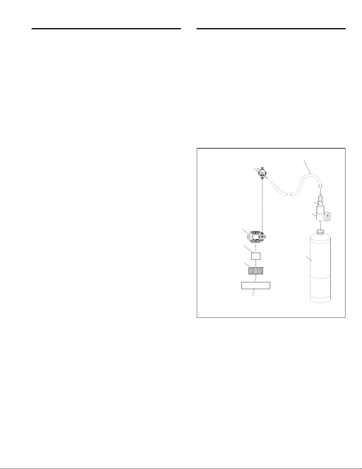
Calibration Cup
CMS-4 Monitor
Velcro®
Loop Tape
Velcro®
Hook Tape
Transparent
Mounting Strip
Tubing 3/16" x 2 Ft
0.5 LPM Slide Valve
Calibration
Connector
CLEMCO
25 ppm CO
Test Gas
O
N
P
E
C
LES
O
Figure 1
1.7.7 LCD: A digital LCD (liquid crystal display) is
visible through the clear plastic window in the top of the
case. During normal operation in Measuring Mode, the
LCD displays CO concentrations, the time, remaining
battery life, and the heart symbol pulses, indicating the
monitor is in normal operating status. The LCD also
shows information for each of the CMS-4’s operating
modes. Once the monitor is ON, pressing the
Power/Mode or Air control button turns on the LCD
backlight for 30 seconds. NOTE: Except in dark places,
the display is easily seen without the backlight.
© 2019 CLEMCO INDUSTRIES CORP. www.clemcoindustries.com Manual No. 29872
Page 9

CMS-4 IN-HELMET CARBON MONOXIDE MONITOR Page 4
CMS-4 callouts shown are items
needed to perform routine functions.
Cover Screw
Sensor Retainer
LED Alarm-Lens
Audible Alarm Opening
AIR Button
POWER/MODE Button
LCD Window
Sensor Retainer
CLEMCO
Hydrophobic Filter (white)
Charcoal Filter (black)
Sensor Gasket
Sensor Orientation Slots
Velcro® Loop Tape
Velcro® Hook Tape
Sensor
Mounting Clip
Figure 2
1.7.8 Control Buttons: Two control buttons, AIR and
POWER/MODE, are located below the LCD. The
functions performed by the control buttons are
summarized in the table in Figure 3.
They turn the CMS-4 ON and OFF. They control what is
displayed on the LCD, including time, gas
concentrations, as well as other messages. They also
allow for a fresh-air adjustment, change alarm points,
change the time, and calibrate the instrument.
NOTE: Important points to remember are:
1. The AIR button scrolls through items on the
menus much like a cursor. Once the menu
item is selected, use the POWER/MODE to
enter the selection into the microprocessor.
2. To reverse the direction of change (i.e. from
increasing to decreasing or vice versa):
a. Press and hold AIR.
b. Immediately press POWER/MODE
and then release both buttons.
NOTE: Each screen displays for 20 seconds. If you
do not press a button within 20 seconds, the CMS-4
automatically returns to Measuring Mode.
Button Function
POWER/MODE
AIR
Turns the monitor ON and OFF.
Activates Display Mode.
Enters instruction into CMS-4’s
microprocessor.
Resets alarm after an alarm
condition.
Also
Turns the LCD backlight on
(when monitor is on).
.
Activates the Demand Zero
function (adjusts the CMS-4’s
fresh-air baseline).
Enters instructions into the
CMS-4’s microprocessor.
Increases the value of a
parameter available for
adjustment.
Scrolls through parameter
options.
Also
Turns the LCD backlight on
(when monitor is on).
Figure 3
© 2019 CLEMCO INDUSTRIES CORP. www.clemcoindustries.com Manual No. 29872
Page 10

CMS-4 IN-HELMET CARBON MONOXIDE MONITOR Page 5
1.7.9 Alarm-Lights: Two LED alarm-lights are located
above the LCD. The red alarm-lights show through
the reflective lenses. The LED’s alert the user to CO
gas, low battery, and failure alarms. The lights flash
once during the startup sequence.
1.7.10 Audible Alarm: An opening on the left side of
the top case allows the alarm’s sound to exit the case.
The alarm sounds for CO gas, unit malfunctions, low
battery voltage, and as an indicator during normal use of
various display options. It beeps once during the startup
sequence. Refer to Section 3.1 for alarm indications.
1.7.11 Vibrating Alarm: A vibrating motor mounted
inside the case vibrates for CO gas alarms, unit
malfunctions, and as an indicator during normal use of
the various modes of the CMS-4. It vibrates briefly
during the startup sequence.
1.7.12 Lithium Battery: A CR2450, 3.0-volt lithium
coin battery powers the CMS-4. The battery icon in the
upper right of the LCD shows remaining battery life.
When the CMS-4 detects a low battery voltage, a low
battery warning is activated. When battery power is too
low for Measuring Mode, the CMS-4 sounds a dead
battery alarm. (Gas reading disappears, FAIL appears in
the middle of the screen, BATTERY appears at the
bottom of the screen, LEDs flash once per second, and
audible alarm double pulses once per second.)
A spare battery is provided with the monitor; refer to
Section 6.1 for instructions on replacing the battery.
2.0 SETUP ‒ INSTALLATION, STARTUP AND
OPERATION
2.1 Installation
This section explains the initial installation of the CMS-4
to the inside of the respirator.
2.1.1 Prepare Mounting Clip
2.1.1.1 Adhere Velcro
Trim the Velcro
®
®
loop to CMS-4 mounting clip:
loop strip to 3/4" x 1". Remove the
backing and adhere it to the bottom of the monitors
mounting clip, as shown in Figure 4.
2.1.2 Installing Monitor in Apollo 20 Respirator
Refer to Section 2.1.3 for installing the monitor in Apollo 60
and Apollo 600 respirators.
2.1.2.1 If not already done, adhere the Velcro
CMS-4 mounting clip, per Section 2.1.1.
© 2019 CLEMCO INDUSTRIES CORP. www.clemcoindustries.com Manual No. 29872
®
loop to
3/4" x 1-1/4"
®
Velcro
Velcro
Loop Strip
Back of Monitor
3/4" x 1-1/4"
®
Loop Strip
Mounting Clip
End View of Monitor
Mounting Clip
Figure 4
2.1.2.2 Open the lens frame and remove the lenses.
2.1.2.3 Don (put on) the helmet and temporarily place the
monitor on one of the side walls of the window extension,
as shown in Figure 5. Make sure the monitor’s LED lights
are visible.
2.1.2.4
Mark the location and remove the monitor and helmet.
Make sure the monitor’s
LED lights are visible when
the helmet is donned, mark
its location inside of the
window extension, and
attach Velcro
®
hook tape.
Figure 5
2.1.2.5 Remove backing from the Velcro
®
hook tape and
adhere it at the marked location (the loop tape adheres to
the mounting clip on the monitor). Use the Velcro
attach the monitor to the hood, positioning it so the
control buttons face toward lenses and alarm-lights
toward the inside of the respirator. Don the helmet to
make sure the monitor’s alarm-lights are visible from
inside the helmet.
2.1.2.6 Remove the monitor and prepare it for operation,
per Section 2.2.
2.1.2.7 Replace the lenses and lens frame assembly.
2.1.2.8 After the initial setup is done, remove and
reattach the monitor using the Velcro
®
. Remove the
®
to
Page 11

CMS-4 IN-HELMET CARBON MONOXIDE MONITOR Page 6
W
W
W
monitor when doffing (taking off) the respirator at
the end of the shift and to do any service or
calibration, including turning the monitor on and off.
Do this to make sure the monitor is fully functional before
placing it inside the helmet.
ARNING
Remove the monitor at the end of the shift, turn
it off, and store it in a clean environment. At the
beginning of each shift, turn on the monitor and
make sure it is fully functional before installing it
in the helmet. Failure to do so could result in CO
poisoning and death.
2.1.3 Installing Monitor in Apollo 60 and Apollo
600 Respirators
Refer to Section 2.1.2 for mounting the monitor in Apollo 20
respirators.
2.1.3.1 If not already done, adhere the Velcro
CMS-4 mounting clip, per Section 2.1.1.
2.1.3.2 Place the transparent mounting strip on the
inside of the inner lens, and into the same window
gasket groove as the inner lens, as shown in Figure 6.
Position it so it is within peripheral vision toward the side
of the window opening.
As seen from inside the hood,
the strip is inserted into the
groove in the window gasket.
Attach Velcro
the inside of the strip. Make
sure the monitor’s LED lights
are visible when the helmet is
donned.
Figure 6
2.1.3.3 Remove backing from the Velcro
and adhere it to the mounting strip (the loop tape
adheres to the mounting clip on the monitor) making sure
the LED lights are visible from inside the helmet.
2.1.3.4 Attach the monitor to the strip, positioned so the
buttons face toward the outer edge of the window
opening and LED lights toward the center of the window
opening. Don (put on) the helmet to make sure the
monitor LED lights are visible from inside the helmet.
2.1.3.4 Remove the monitor and prepare it for operation.
®
hook tape to
®
loop to
®
hook tape
2.1.3.6 After the initial setup is done, remove and
reattach the monitor from inside the helmet. Remove
the monitor when doffing the respirator at the end of
the shift and to do any service or calibration,
including turning the monitor on and off. Do this to
make sure the monitor is fully functional before placing it
inside the helmet.
ARNING
Remove the monitor at the end of the shift, turn
it off, and store it in a clean environment. At the
beginning of each shift, turn on the monitor and
make sure it is fully functional before installing it
in the helmet. Failure to do so could result in CO
poisoning and death.
2.2 Turning ON and Startup Procedure
This section explains how to startup the CMS-4 and to
prepare it for operation.
2.2.1 Press and hold the POWER/MODE button until the
alarm beeps.
2.2.2 The monitor goes though the warm-up
sequence: all LCD segments turn on, backlight turns on,
and instrument beeps and vibrates. It then cycles
through calibration status, date/time, remaining battery
life, target gas, and alarm setpoint screens.
2.2.3 After the warm-up sequence, the monitor goes
into Measuring Mode (normal operating mode). It beeps,
the LCD screen (as shown in Figure 8) shows CO,
remaining battery life, a pulsing heart symbol (indicating
the monitor is in normal operating status), CO
concentrations (ppm), and the date and time (when set
per Section 2.3).
ARNING
If the monitor is in low battery warning, change
the battery as soon as possible. Do not use the
respirator if the dead battery warning is alarmed.
The monitor does not detect carbon monoxide
when it is in dead battery alarm, which can result
in death if carbon monoxide is present.
2.3 Setting the Date and Time ‒ Figure 7
NOTE: When using the CMS-4 for the first time, check
the current time and verify that it is correct for your time
zone. If it is not, set the time as follows:
© 2019 CLEMCO INDUSTRIES CORP. www.clemcoindustries.com Manual No. 29872
Page 12

CMS-4 IN-HELMET CARBON MONOXIDE MONITOR Page 7
O
0
2.3.1 With the instrument turned OFF, press and hold
AIR and POWER MODE. Release when you hear a
beep. BUMP is displayed.
2.3.2 Press and release the AIR button to scroll to
DATE.
2.3.3 Press and release POWER/MODE. The date
and time will be displayed with the year flashing.
2.3.4 Use AIR to display the desired year. To reverse
the direction of change (i.e. from increasing to
decreasing or vice versa):
a. Press and hold AIR.
b. Immediately press POWER/MODE and then
release both buttons.
LCD Window
Year
Battery Icon
2019
Date
8.03
Time
12:34
Figure 7
2.3.5 Press POWER MODE to save it. The month
starts to flash.
2.3.6 Use AIR to adjust the month. Press POWER
MODE to save it. The day starts to flash.
2.3.7 Repeat the process to set the day, hour, and
minute. The time is shown in military format with the
hour going from 0 to 24.
2.3.8 Use AIR to scroll to START. Press and release
POWER MODE to begin the warm-up sequence. NOTE:
If no button is pressed within 20 seconds, the monitor
will automatically return to measuring mode.
2.4 Performing a Fresh-Air Adjustment
NOTE: Before using the CMS-4, set the fresh-air
baseline to ensure accurate gas readings.
Additional fresh-air adjustment information is in Section
5.2.
Heart Symbol
Pulses, indicating the
monitor is in normal
operating status.
2.4.1 Make sure the monitor is in a fresh-air
environment. This is an environment free of toxic or
combustible gases and of normal oxygen content
(20.9%).
2.4.2 Turn on the monitor by pressing and holding the
POWER/MODE button until the alarm beeps.
2.4.3 The monitor goes though the warm-up
sequence, as noted in Paragraph 2.2.2.
2.4.4 After the warm-up sequence, the monitor goes
into Measuring Mode (normal operating mode), it beeps,
and the LCD display is as shown in Figure 8.
2.4.5 Press and hold the AIR button. While pressing
the AIR button, the LCD displays HOLD, a prompt to
keep pressing the AIR button.
2.4.6 When the fresh-air baseline has been set, the
LCD displays Adj, and a prompt to RELEASE the AIR
button. The monitor beeps once and the screen displays
0 ppm, as shown in Figure 8.
2.4.7 The monitor is now in Measuring Mode (normal
operation). After an initial calibration per Section 5.7, the
CMS-4 is ready for monitoring.
LCD Window
C
Figure 8
2.5 Turning OFF the CMS-4
2.5.1 Remove the monitor after doffing (taking off) the
respirator at the end of the shift.
2.5.2 Press and hold the POWER/MODE button.
2.5.3 OFF will appear on the screen and the monitor
will beep for about five seconds. Release the button
when OFF disappears from the screen and the LCD is
blank. The monitor is off.
Time
Gas
ppm
12:34
Battery Icon
Heart Symbol
Pulses, indicating the
monitor is in normal
operating status.
Current Gas (CO)
Concentration
© 2019 CLEMCO INDUSTRIES CORP. www.clemcoindustries.com Manual No. 29872
Page 13

CMS-4 IN-HELMET CARBON MONOXIDE MONITOR Page 8
3.0 Alarms
This section covers alarm indications. It also explains
how to respond to an alarm condition and how to reset
the CMS-4 after an alarm has occurred.
3.1 Alarm Indications
3.1.1 Audible Alarms
Gas Alarms: Alternating high-low tone ‒ chirps occur
about once per second.
Fault Alarms: Double-pulsing beep occurring about
once per second.
In addition to the audible alarms, the monitor vibrates,
and the LEDs flash when any sort of alarm condition or
failure is encountered.
3.2 Alarm Indications Table: Refer to table in
Figure 9 on the following page for Alarm Type, Visual
Indications, and other alarm indications
3.3 Resetting CO Alarms
3.3.1 The CMS-4 remains in alarm until the alarm
conditions passes and POWER/MODE is pressed.
NOTE: Even though the gas concentration may have
fallen below the alarm point, the alarm indications will
continue until the alarm is reset using the
POWER/MODE button, as noted in the paragraph
below. A PEAK alarm display cannot be cleared until the
monitor is turned OFF. If a TWA or STEL alarm has been
activated, it cannot be reset unless the monitor is turned
OFF.
3.3.2 To reset a CO gas alarm, after the CO reading
falls below the low-alarm point (10 ppm), press and
release the POWER/MODE button once.
3.4 Responding to Alarms
This section describes responses to gas, over range,
battery, sensor failure, clock failure, and system failure
alarms.
3.4.1 Responding to CO Alarms
3.4.1.1 Follow an established procedure for responding
to CO gas alarms. It should include but not be limited to
removing the respirator as soon as it is safe to do so.
3.4.1.2 Reset the alarm by pressing and releasing the
POWER/MODE button once after the CO reading falls
below the low alarm point.
© 2019 CLEMCO INDUSTRIES CORP. www.clemcoindustries.com Manual No. 29872
3.4.2 Responding to an Over Range Alarm
An over range alarm could indicate CO gas is above the
detection limit of 1000 ppm. The CO concentration
reading is replaced by blinking brackets (ΠΠΠΠ).
WARNING
An over range condition may indicate an
extreme CO concentration. Remove the
respirator as quickly as possible when it is safe
to do so.
3.4.2.1 Follow an established procedure for responding
to CO gas alarms. It should include but not be limited to
removing the respirator as soon as it is safe to do so.
3.4.2.2 Reset the alarm using POWER/MODE once the
alarm condition has cleared.
3.4.2.3 Calibrate the CMS-4, as described in Section 5.7.
3.4.2.4 If the Over Range condition continues, the
sensor may need to be replaced.
3.4.2.5 If the Over Range condition continues after
replacing the sensor, contact the authorized Clemco
distributor the monitor was purchased through for further
instructions.
3.4.3 Responding to Battery Alarms
WARNING
The CMS-4 is not operational during a dead
battery alarm. Do not use the respirator until
the battery is replaced. Breathing compressed
air while a monitor is not operational can result
in death if carbon monoxide is present.
3.4.3.1 The CMS-4 is fully functional during a low
battery warning. However, only a limited amount of
operating time remains. The amount of time depends on
how often the LCD backlight is used and how often the
monitor responds to alarm conditions. Replace the
battery as soon as possible when a low battery warning
occurs. Refer to Section 6.1: Replacing the Lithium
Battery.
NOTE: Alarms and the LCD backlight consume
battery power and reduce the amount of operating
time remaining.
Page 14

CMS-4 IN-HELMET CARBON MONOXIDE MONITOR Page 9
ALARM TYPES AND INDICATIONS
ALARM TYPE VISUAL INDICATIONS OTHER ALARM INDICATIONS
WARNING
Concentration of CO
rises above the Warning
setting (10 ppm).
Alarm
Concentration of CO
rises above alarm
setting of 10 ppm.
Alarm H
Concentration of CO
rises above the high
alarm setting of 10 ppm.
TWA or STEL
Concentration of CO
rises above the TWA or
STEL alarm setting.
Over Range
An over range condition
indicates an extreme CO
concentration.
Low Battery Warning
Dead Battery Alarm
Sensor Failure
System Failure
Clock Failure
Gas reading flashes.
Warning appears at the bottom of the LCD.
Alarm LEDs flash.
Backlight turns on.
Gas reading flashes.
Alarm appears at the bottom of the LCD.
Alarm LEDs flash.
Alternating high-low tone ‒
chirps about twice per second.
Vibrator pulses once per second.
Alternating high-low tone ‒
chirps about twice per second.
Vibrator pulses once per second.
Backlight turns on.
Gas reading flashes.
Alarm H appears at the bottom of the LCD.
Alarm LEDs flash.
Alternating high-low tone ‒
chirps about twice per second.
• Vibrator pulses once per second.
Backlight turns on.
Gas reading flashes.
TWA or STEL appears at the bottom of the
LCD.
Alarm LEDs flash once per second.
Backlight turns on.
Gas reading is replaced with a flashing
ΠΠΠΠ.
Gas name and units flash.
OVER appears at the bottom of the LCD.
Alarm LEDs flash twice per second.
Backlight turns on.
The last bar in the battery icon disappears
and the battery icon starts flashing.
Alarm LEDs flash once per second.
Gas reading disappears.
FAIL appears in the middle of the screen
Alternating high-low tone ‒
chirps about twice per second.
•
Vibrator pulses once per second.
Alternating high-low tone ‒
chirps about twice per second.
Vibrator pulses once per second.
None.
Double pulsing beep occurring about
once per second
and BATTERY appears at the bottom of
the screen.
Alarm LEDs flash once per second
FAIL appears in the middle of the screen and
SENSOR appears at the bottom of the
Double pulsing beep occurring about
once per second.
screen.
Alarm LEDs flash once per second.
Gas reading replaced by FAIL.
Time replaced by SYS below FAIL.
• FAIL 050 CLOCK appears on the screen.
Alarm LEDs flash once per second.
Figure 9
Double pulsing beep occurring about
once per second.
Double pulsing beep occurring about
once per second.
© 2019 CLEMCO INDUSTRIES CORP. www.clemcoindustries.com Manual No. 29872
Page 15

CMS-4 IN-HELMET CARBON MONOXIDE MONITOR Page 10
3.4.4 Responding to a Sensor Failure Alarm
3.4.4.1 Perform a calibration, as described in Section 5.7.
3.4.4.2 If the sensor failure alarm continues, replace the
sensor, as described in Section 6.2.
3.4.4.3 If the sensor failure alarm continues after
replacing the sensor, contact the authorized Clemco
distributor the monitor was purchased through for further
instructions.
3.4.5 Responding to Clock Failure Alarm ‒ Figure 10
A clock failure alarm occurs if the monitor’s internal clock
malfunctions.
FAIL
050
CLOCK
Figure 10
3.4.5.1 If the error code is 050, press and release
POWER/MODE to continue into Measuring Mode if the
instrument must be used temporarily.
3.4.5.2 Attempt to set the date using the DATE menu
item in User Mode. Refer to Section 2.3: Setting Date
and Time.
3.4.5.3 If the date cannot be set correctly, contact the
authorized Clemco distributor the monitor was
purchased through for further instructions.
3.4.6 Responding to a System Failure Alarm
3.4.6.1 If a system failure occurs, the system failure
screen will display an error code similar to that shown in
Figure 11.
3.4.6.2 If the System Failure error code is anything but
031, as shown in Figure 11, the instrument cannot be
used. Contact Clemco Industries as soon as possible.
If the error code is 031, press and release
POWER/MODE to continue into Measuring Mode if the
instrument must be used temporarily.
FAIL
031
SYSTEM
Figure 11
3.5 Alarm Setpoints
3.5.1 There are six alarm points. The alarm points and
their factory settings are summarized below. There are
no adjustments of alarm setpoints.
*F. S. (Full Scale): Is triggered when CO
concentrations go over the scale maximum of 1000
ppm.
WARNING: Is triggered when CO concentrations
reach 10 ppm, which is the maximum exposure limit
for Grade D compressed air in the United States.
Alarm: Is triggered when CO concentrations reach
10 ppm.
Alarm H: Because the maximum exposure limit for
grade D breathing air is 10 ppm of CO, the high
alarm is also set to alarm when CO concentration
reaches 10 ppm. This alarm is a rapid, twice per
second beep and stresses the urgency to remove
the respirator as soon as it is safe to do so.
*TWA Alarm: TWA is an acronym for time-weighted
average; it is the average reading of CO during the
last eight hours. The alarm triggers when TWA
reaches 25 ppm
*STEL Alarm: STEL is an acronym for short-term
exposure limit; it is the average reading of CO
during the last 15 minutes. The alarm triggers when
STEL reaches 200 ppm
* Although some may find Full Scale, TWA and STEL
information useful, it is not relevant for supplied-air
respirator use because the maximum exposure limit for
Grade D breathing air is 10 ppm.
4.0 MANEUVERING THROUGH MENU MODES
This section helps the user maneuver through CMS4 menu items. The menu item under each mode is
listed in sequential order.
4.1 MEASURING MODE ‒ Measuring Mode is the
normal operating mode used to detect CO and observe
© 2019 CLEMCO INDUSTRIES CORP. www.clemcoindustries.com Manual No. 29872
Page 16

CMS-4 IN-HELMET CARBON MONOXIDE MONITOR Page 11
W
W
O
0
any alarm indications. The monitor must be in measuring
mode before it is placed in the respirator.
The CMS-4 is not operational as a carbon
monoxide monitor unless it is Measuring Mode.
The monitor must be in Measuring Mode before
it is placed in the respirator. Failure to ensure
the monitor is in Measuring Mode can result in
death if carbon monoxide is present.
4.1.1 Entering Measuring Mode
4.1.1.1 Make sure the monitor is OFF. (Press and hold
POWER/MODE until the screen is blank.)
4.1.1.2 Turn on the monitor by pressing and holding the
POWER/MODE button until the alarm beeps.
4.1.1.3 After the warm-up sequence, the monitor goes
into Measuring Mode (normal operating mode) when the
alarm beeps and the LCD screen is as shown in Figure
12 and indicates the current gas concentration. After an
initial calibration per Section 5.7, the CMS-4 is ready for
monitoring.
LCD Window
C
Figure 12
4.2 USER MODE ‒ User Mode is used to do bump
tests, calibrate the monitor, and make minor screen
adjustments used primarily to calibrate the monitor.
The CMS-4 is not operational as a carbon
monoxide monitor while in User Mode. The
monitor must be in Measuring Mode before it is
placed in the respirator. Failure to ensure the
monitor is in Measuring Mode can result in
death from carbon monoxide poisoning.
Time
ARNING
Gas
Battery Icon
Heart Symbol
Pulses, indicating the
monitor is in normal
ppm
12:34
operating status.
Current Gas (CO)
Concentration
ARNING
© 2019 CLEMCO INDUSTRIES CORP. www.clemcoindustries.com Manual No. 29872
4.2.1 Entering User Mode
Begin with the monitor OFF.
4.2.1.1 Press and hold the AIR button, then press and
hold the POWER/MODE button. Release both buttons
as soon as the monitor beeps.
4.2.2 Tips for Using User Mode
To scroll from one menu item to the next, press
AIR and release it as soon as the alarm beeps.
To reverse the scroll direction:
a. Press and hold AIR.
b. Immediately press POWER/MODE and then
release both buttons.
4.2.3 To cycle through each of the user mode menus,
press POWER/MODE and release it as soon as the
alarm beeps
4.2.4 The first screen to appear will be BUMP, as
shown in Figure 13.
BUMP
Figure 13
Refer to Section 5.6 to perform a bump test.
4.2.5 To scroll to the next menu item (GAS CAL),
press and release POWER/MODE. Continue to press
and release POWER/MODE to scroll through every
menu item.
4.2.6 Refer to the table in Figure 14 on the following
page for a sequential list of the items found in User
Mode, the page that the menu item’s instructions can be
found on, and a short description of the menu item.
4.2.7 Display Firmware Version.
4.2.7.1 Enter User Mode, per Section 4.2.1.
4.2.7.2 Press and release AIR and scroll to ROM/SUM.
4.2.7.3 Press and release POWER/MODE. The screen
will cycle through the boards and display the ROM as
the top value and SUM as the bottom value.
Page 17

CMS-4 IN-HELMET CARBON MONOXIDE MONITOR Page 12
W
SEQUENTIAL LIST OF USER MODE MENU ITEMS
Number of Times
POWER/MODE (beeps)
is pressed and released
to reach menu item.
ONE
TWO
THREE
FOUR
FIVE
SIX
SEVEN
EIGHT
NINE
TEN
ELEVEN
TWELVE
THIRTEEN
FOURTEEN
FIFTEEN
Figure 14
User Mode Menu Items Description Section in Which
Adjustments are Found
BUMP
GAS CAL
CAL SET
BUMP SET
ALARM-P
LUNCH
BEEP
BL TIME
KEY.TONE
DISP.SET
E-CAL
DATE
PASS W
ROM/SUM
START
Perform bump test.
Perform a calibration.
Changes parameters related to
calibration.
Changes setting related to bump testing.
Set and alarm points.
Resets TWA and STEL readings at
startup.
Sets confirmation beep parameters.
How long backlight stays on.
Sets whether or not alarm beeps when
button is pressed.
Sets user ID, Station ID, and Alarm
Volume.
A-CAL item appears in GAS CAL menu.
E-CAL. Factory setting is OFF.
Sets the Date and Time. Refer to Section 2.3.
When set to ON, password required
to enter User Mode.
Shows firmware version and
firmware checksum.
Enters Measuring Mode from User
Mode.
Refer to Section 5.6.
Refer to Section 5.7.
No adjustment required.
Do not adjust.
No adjustment required.
Do not adjust.
No adjustment required.
Do not adjust.
No adjustment required.
Do not adjust.
No adjustment required.
Do not adjust.
No adjustment required.
Do not adjust.
Factory setting is ON.
Do not adjust.
Factory setting is ON.
Do not adjust.
Factory setting is OFF.
Do not adjust.
Factory setting is OFF.
Do not adjust.
Refer to Section 4.2.7
to display firmware.
Press and release
POWER/MODE.
4.3 DISPLAY MODE ‒ Display mode is used to
view and change settings of menu items noted in the
table in Figure 15. Refer to the table for a list of the items
found in Display Mode, a short description of the menu
item’s function, and the section that the menu item’s
instructions can be found.
ARNING
The CMS-4 is not operational as a carbon
monoxide monitor while in Display Mode. The
monitor must be in Measuring Mode before it is
placed in the respirator. Failure to ensure the
monitor is in Measuring Mode can result in
death from carbon monoxide poisoning.
4.3.1 Entering Display Mode
4.3.1.1 Enter Display Mode using one of the two
following methods:
1. From Measuring Mode (normal operating mode)
press POWER/MODE and release it as soon as the
alarm beeps. The monitor is now in Display Mode.
2. If the monitor is OFF:
a. Press and hold POWER/MODE until the alarm
beeps.
b. After the warm-up sequence, the monitor goes into
Measuring Mode (normal operating mode). It beeps,
the LCD screen (as shown in Figure 12) shows CO,
remaining battery life, a pulsing heart symbol
(indicating the monitor is in normal operating status),
© 2019 CLEMCO INDUSTRIES CORP. www.clemcoindustries.com Manual No. 29872
Page 18

CMS-4 IN-HELMET CARBON MONOXIDE MONITOR Page 13
CO concentrations (ppm), and the date and time
(when set per Section 2.3). Review Section 2.2:
Turning On and Startup Procedure.
c. From Measuring Mode (normal operating mode),
press POWER/MODE and release it as soon as the
alarm beeps. The monitor is now in Display Mode.
4.3.2 Tips for Using Display Mode
To scroll from one menu item to the next, press
POWER/MODE and release it as soon as the
alarm beeps.
To enter an item, press and release AIR.
To reverse the direction of a flashing parameter,
(i.e. from increasing to decreasing or vice
versa):
a. Press and hold AIR.
b. Immediately press POWER/MODE and then
release both buttons.
SEQUENTIAL LIST OF DISPLAY MODE MENU ITEMS
NOTE: Each screen displays for 20 seconds. If a
button is not pressed within 20 seconds, the CMS-4
automatically returns to Measuring Mode.
4.3.3 To cycle through each of the following display
mode menus, press POWER/MODE and release it as
soon as the alarm beeps. Refer to the Table in Figure 15
for additional information.
4.3.4 DISPLAY MODE MENU ITEMS (Reference
Table)
Menu items shown with "No Adjustment" have
factory settings that should not be adjusted. If
operator accidentally enters an unfamiliar menu, DO
NOT PUSH BUTTONS THAT COULD CHANGE THE
MONITORS FUNCTION. Refer to Section 4.4 to return
to factory settings.
Number of times
POWER/MODE (beeps)
is pressed and released
to reach menu item.
ONE
TWO
THREE
FOUR
FIVE
SIX
SEVEN
EIGHT HI (Alarm Beep Volume) Sets the buzzer volume. Factory set to
NINE Returns to measuring mode.
Figure 15
Display Mode Menu Items Description Sections In Which
Adjustments Are Found
PEAK
STEL
TWA
dISP (CAL DATA
LCD screen cycles
through CAL.DATA,
YES/AIR, and NO/MODE.
DATE and TIME
TEMP
dISP (ALARM-P
LCD screen cycles
through ALARM-P,
YES/AIR, and NO/MODE
Displays peak (highest) CO
concentration since the monitor was last
turned on.
Disp la ys short- term exposure limit. This
reading is the average reading over the
last 15 minutes.
Displays time-weighted average over the
last 8 hours.
Shows date of last calibration.
Factory set to ON.
Displays Year, Date, and Time. Set per Section 2.3.
Displays ambient temperature in Celsius. Not adjustable.
View alarm setpoints. No adjustment required.
high.
No adjustment required.
Do not adjust.
No adjustment required.
Do not adjust.
No adjustment required.
Do not adjust.
No adjustment required.
Do not adjust.
Do not adjust.
No adjustment required.
Do not adjust.
© 2019 CLEMCO INDUSTRIES CORP. www.clemcoindustries.com Manual No. 29872
Page 19

CMS-4 IN-HELMET CARBON MONOXIDE MONITOR Page 14
W
E
R
D
R
5
O
O
0
4.3.5 Displaying the PEAK Screen
4.3.5.1 The PEAK screen displays the highest CO
concentration detected since the CMS-4 was turned ON.
The PEAK reading is stored until a higher level is
detected, the PEAK reading is cleared, or the CMS-4 is
turned OFF.
4.3.5.2 PEAK readings are automatically cleared when
the monitor is turned OFF or cleared (as noted beginning
with Paragraph 4.3.5.3), and restarted when the monitor
is turned ON.
4.3.5.3 Make sure the monitor is in Display Mode, as
noted in Section 4.3.1.
4.3.5.4 Press and release POWER/MODE until PEAK
appears in the lower-left corner of the LCD screen, as
shown in Figure 16.
C
1
ppm
The number shown in the
illustration is for reference
only. The number shown
on the LCD screen will be
the actual peak reading.
PEAK
Figure 16
4.3.5.5 To clear the peak reading, do the following while
remaining in Display Mode:
1. While PEAK appears on the screen, press Air
and hold (as shown in the left image in Figure
17), and release it when prompted (as shown in
right image).
2. The peak reading will be reset and the display
will return to the Peak Screen.
3. After 20 seconds, the monitor will return to
Measuring Mode.
Figure 17
CL
HOL
CL
RELEAS
4.3.6 Displaying the STEL Screen ‒ Figure 18
4.3.6.1 The STEL Screen displays the short-term
exposure limit (STEL) reading. The STEL reading is the
average reading over the last 15 minutes. There are no
changes or resets on the STEL menu.
The number shown in
the illustration is for
C
ppm
STEL
Figure 18
4.3.7 Displaying the TWA Screen
4.3.7.1 The TWA Screen displays the time-weighted
average (TWA) reading. The TWA reading is the
average reading over the last 8 hours. If 8 hours have
not elapsed since the last time the TWA reading was
cleared, the average is still calculated over 8 hours. The
missing readings are assigned a value of 0.
4.3.8 TWA readings are automatically cleared when
the monitor is turned OFF and begins collecting new
TWA readings when the monitor is turned ON.
4.4 MAINTENANCE MODE
NOTE: Maintenance Mode Changes settings that
operationally affect the instrument.
Maintenance Mode settings affect the operation
of the monitor and should only be cautiously
changed. Changing settings on an impulse can
lead to false or no alarms, resulting in carbon
monoxide poisoning, death, or serious injury.
4.4.1 Return to Factory Default Settings: The only
function we advise using in Maintenance Mode is to
default to factory settings when menu items have been
unintentionally changed. These changes are identified
when menu items on the screen do not match menu
items in the instructions.
ARNING
reference only. The
number shown on the
LCD screen will be the
average STEL reading
over the last 15 minutes.
© 2019 CLEMCO INDUSTRIES CORP. www.clemcoindustries.com Manual No. 29872
Page 20

CMS-4 IN-HELMET CARBON MONOXIDE MONITOR Page 15
W
4.4.2 Entering Maintenance Mode
ARNING
The CMS-4 is not operational as a carbon
monoxide monitor while in Maintenance Mode.
The monitor must be in Measuring Mode before
it is placed in the respirator. Failure to ensure
the monitor is in Measuring Mode can result in
death if carbon monoxide is present.
4.4.2.1 Make sure the monitor is OFF. (Press and hold
POWER/MODE until the screen is blank.)
4.4.2.2 Press and hold AIR, then press and hold
POWER/MODE. Continue to hold the buttons down after
the first beep.
4.4.2.3 Release both buttons after the second beep.
The LCD screen should be as shown in Figure 19 with
the digit on the left flashing.
0 0 0 0
4.4.3 Performing a Default (M.DEF)
NOTE: Performing a default operation in Maintenance
Mode returns all parameters to their factory settings.
4.4.3.1 Enter Maintenance Mode, per Section 4.4.2.
4.4.3.2 Press and release AIR 16 times and scroll to
M.DEF.
4.4.3.3 Press and release POWER/MODE. The screen
will alternate between M.DEF, YES.MODE, and NO.AIR.
4.4.3.4 Press and release POWER/MODE to perform a
default operation.
4.4.3.5 The monitor will ask if you are sure you want to
perform a default operation by alternating between
SURE?, YES.MODE, and NO.AIR.
4.4.3.6 Press and release POWER/MODE. The monitor
will beep twice, briefly display PASS, and return to MDEF.
4.4.3.7 To return to Measuring Mode (normal operating
mode), press and release AIR once and press and
release POWER/MODE. The monitor will begin the
warm-up sequence and enter measuring mode.
PASS - W
Figure 19
4.4.2.4 The factory-set password is 3000.
4.4.2.5 Enter the password by using AIR to select each
password number and then press and release
POWER/MODE to save it and move on to the next
number until all of the numbers are entered. To reverse
the direction of change (i.e. from increasing to
decreasing or vice versa):
a. Press and hold AIR.
b. Immediately press POWER/MODE and then
release both buttons.
5.0 CALIBRATION, FRESH-AIR ADJUSTMENTS,
BUMP TEST, and STORAGE
This section covers:
Calibration Schedule
Performing Fresh-Air Adjustments
a) Setting the adjustment with ambient air.
b) Setting the adjustment with impurity-free test gas.
Prepare Calibration Connector for Calibration.
Connect Calibration Cup to Monitor
Remove Calibration Cup from Monitor
Performing a Bump Test
Calibrating the CMS-4
Storing the Calibration Connector and Test Gas
WARNING
Use a 0.5 LPM (liters per minute) fixed-flow,
calibration-connector regulator valve (Clemco
Stock No. 25572) when calibrating. Use of a
different flow rate will adversely affect the
accuracy of the calibration.
© 2019 CLEMCO INDUSTRIES CORP. www.clemcoindustries.com Manual No. 29872
Page 21

CMS-4 IN-HELMET CARBON MONOXIDE MONITOR Page 16
O
0
5.1 Calibration Schedule
5.1.1 Once the date and time are set, per Section 2.3,
the monitor displays a reminder that a bump test and/or
calibration are due. Factory setting are:
Bump test reminder is set for 30 days.
Calibration reminder is set for 90 days.
Initial Calibration Schedule: To become familiar with the
operation and settings of the monitor the following initial
schedule should be observed:
Do a bump test daily for the first week of operation.
Refer to Section 5.6.
Calibrate weekly for the first month of operation.
Refer to Section 5.7.
Follow bump test and calibration reminder
schedules thereafter.
Bump test before use if the monitor was out of
service for more than one week.
5.2 Performing Fresh-Air Adjustments
Fresh-air adjustments must be done in a fresh-air
environment, free of toxic or combustible gases and with
normal oxygen content (20.9%). The usual method is to
set it in fresh ambient air. If fresh, ambient air cannot
be assured, set the fresh-air baseline with impurityfree (0 ppm) test gas, as described in Section 5.2.2.
5.2.1 Fresh-Air Adjustment with Ambient Air
5.2.1.1 Turn ON the CMS-4 by pressing and holding the
POWER/MODE button until the alarm beeps. Allow the
monitor to finish its warm-up sequence.
5.2.1.2 Press and hold the AIR button. While pressing
the AIR button, the LCD displays HOLD, a prompt to
keep pressing the AIR button.
5.2.1.3 When the fresh-air baseline has been set, the
LCD displays “Adj,” and a prompt to RELEASE the AIR
button. The monitor beeps once and the screen displays
0 ppm, as shown in Figure 20.
LCD Window
C
Figure 20
Time
Gas
ppm
12:34
Battery Icon
Heart Symbol
Pulses, indicating the
monitor is in normal
operating status.
Current Gas (CO)
Concentration
5.2.1.4 The monitor is now in Measuring Mode (normal
operation). After an initial calibration per Section 5.7, the
CMS-4 is ready for monitoring.
5.2.2 Fresh-Air Adjustment with Impurity-Free (0
ppm CO) Test Gas
The following is required to set the fresh-air baseline
with impurity-free test gas:
Impurity-free test gas, Stock No. 11132
Calibration connector with 0.5 LPM fixed-flow slide
valve, tubing, and calibration cup.
5.2.2.1 Make sure the monitor is off.
5.2.2.2 Prepare the calibration-connector regulator
valve and impurity-free test gas, per Section 5.3.
5.2.2.3 Turn ON the CMS-4 by pressing and holding the
POWER/MODE button until the alarm beeps. Allow the
monitor to finish its warm-up sequence.
5.2.2.4 Open the connector slide valve by sliding it to
the OPEN position, away from the cylinder.
5.2.2.5 Press and hold the AIR button. While pressing
the AIR button, the LCD displays HOLD, a prompt to
keep pressing the AIR button.
5.2.2.6 When the fresh-air baseline has been set, the
LCD displays “Adj,” and a prompt to RELEASE the AIR
button. The monitor beeps once and the screen displays
0 ppm, as shown in Figure 20.
5.2.2.7 The monitor is now in Measuring Mode (normal
operation). After an initial calibration per Section 5.7, the
CMS-4 is ready for monitoring.
5.2.2.8 Close the connector slide valve by sliding it to
the CLOSE position, toward the test gas cylinder.
5.2.2.9 Remove the calibration cup by gently prying the
retaining clips off the monitor while lifting up on the cup.
Refer to Section 5.5 for additional information on
removing the calibration cup.
5.2.2.10 Unscrew the calibration connector with slide
valve from the test gas cylinder. The test gas cylinder
has a positive seal, whereas the calibration-connector
valve does not. If the connector is not removed from the
test gas cylinder, over time the cylinder will empty.
5.2.2.11 Refer to Section 5.8 for information on storing
the calibration kit and test gas.
© 2019 CLEMCO INDUSTRIES CORP. www.clemcoindustries.com Manual No. 29872
Page 22

CMS-4 IN-HELMET CARBON MONOXIDE MONITOR Page 17
5.3 Prepare Calibration-Connector Regulator
Valve for Calibration ‒ Figure 21
5.3.1 The following materials are required to prepare
the calibration connector and test gas.
1. Calibration Test-Gas Cylinder (25 ppm CO)
Or
Impurity-Free Air Cylinder (used when setting
fresh-air baseline, per Section 5.2.2)
2. Calibration Connector with 0.5 LPM Fixed-Flow
Slide Valve
3. Calibration Tubing
4. Calibration Cup
Flow arrow points away
from calibration tubing.
5.3.5 Screw the calibration connector with slide valve
onto the test gas cylinder. NOTE: Test gas can be 25
ppm CO used to calibrate the monitor, or it can be
impurity-free air used to set fresh-air baseline when
using impurity-free air, per Section 5.2.2.
5.4 Connect Calibration Cup to Monitor ‒ Figure 22
5.4.1 Prepare the calibration connector with slide
valve for calibration, per Section 5.3. Make sure the
connector’s slide valve is closed.
5.4.2 Before attaching the calibration cup onto the
monitor, make sure it is correctly positioned, as shown in
Figure 22. The cup’s flow arrow must point up and to the
left, as shown.
CMS-4 Monitor
Open End of Calibration Cup
Upper Retaining Clip
Calibration Cup
3/16" ID Tubing
Slide Valve
Calibration Connector with
Fixed-Flow Slide Valve
Test Gas Cylinder
OPEN
ESC
L
O
OPEN
CLOSE
Figure 21
5.3.2 Slide one end of the 3/16" clear tubing onto the
barbed end of the calibration connector with slide valve.
5.3.3 Slide the other end of the 3/16" tubing onto the
inlet barb of the calibration cup. NOTE: The calibration
cup (shaded in Figure 21) has directional flow. The
flow-direction arrow shows the direction of air flow.
The tube connects to the barb on the backend of the
flow arrow, as shown. The outlet barb (on the front end
of the flow arrow) remains open.
5.3.4 Make sure the slide valve is CLOSED by sliding
it toward the test gas cylinder, as shown in Figure 21.
CLEMCO
Lower Retaining Clip
Figure 22
3/16" ID Tubing
5.4.3 To attach the cup, refer to Figure 23 and hook
the calibration cup’s lower retaining clip under the lower
slot, as shown in Figure 23.
Calibration Cup
Lower Clip
Tubing
Clip Slot
View from sensor-end of monitor
w
o
r
r
A
w
o
l
F
Upper Clip
Sensor Retainer
Clip Slot
Figure 23
5.4.4 Gently press the other end of the cup onto the
monitor until it snaps into place, as shown in Figure 24.
© 2019 CLEMCO INDUSTRIES CORP. www.clemcoindustries.com Manual No. 29872
Page 23

CMS-4 IN-HELMET CARBON MONOXIDE MONITOR Page 18
Do not force it; if it does not easily snap into place, make
sure the cup’s flow arrow points up and to the left of the
monitor, as shown in Figure 22.
F
l
o
r
w
r
o
A
w
Upper clip inserted
into clip slot.
Calibration cup correctly clipped onto the monitor.
Figure 24
5.4.5 Close the connector slide valve by sliding it to
the CLOSE position, toward the test gas cylinder.
5.4.6 Remove the calibration cup by gently prying the
retaining clips off the monitor while lifting up on the cup.
Refer to Section 5.5 for additional information on
removing the calibration cup.
5.5 Remove Calibration Cup from Monitor
5.5.1 Make sure the connector’s slide valve is closed
by sliding it to the CLOSE position, toward the test gas
cylinder.
5.5.2 To remove the calibration cup from the monitor,
gently pry the upper retaining clip off the monitor while
lifting up on the cup, as shown in Figure 25.
Gently pry upper clip
from clip slot and lift
up to remove.
Figure 25
5.5.3 Unscrew the calibration connector from the test
gas cylinder. The test gas cylinder has a positive seal,
whereas the calibration-connector valve does not. If the
connector is not removed from the test gas cylinder, over
time the cylinder will empty.
5.5.4 Refer to Section 5.8 for information on storing
the calibration kit and test gas.
5.6 Performing a Bump Test
A bump test is a fast way to determine if the monitor is
calibrated within a few ppm of the test gas. If the bump
test fails, a calibration is immediately and automatically
started.
A bump test should be done in a fresh-air environment,
as used to set the fresh-air baseline.
The following are required to bump test the CMS-4:
Test gas with 25 ppm concentration of CO, Stock
No. 25573.
Calibration connector with 0.5 LPM fixed-flow slide
valve, tubing, and calibration cup. Stock No. 29767,
assembled, as noted in Section 5.3.
5.6.1 Make sure the fresh-air baseline was set per
Section 5.2.
5.6.2 Prepare the calibration-connector regulator
valve and 25 ppm CO test gas, per Section 5.3. Make
sure the slide valve is closed.
5.6.3 With the monitor OFF, press and hold AIR and
POWER MODE. Release both buttons when the monitor
beeps. BUMP is displayed on the LCD. The monitor is
now in User Mode.
5.6.4 Press and release POWER/MODE once. The
calibration value (25 ppm) displays on the right side of
the screen.
5.6.5 Connect the calibration cup to the front of the
monitor over the sensor retainer. (The sensor retainer is
located to the right of the LCD screen.) The calibration
cup’s arrow must point up and to the left, as shown in
Figures 21 and 22. Gently press the cup onto the
monitor until it snaps into place. Refer to Section 5.4 for
additional information on connecting the calibration cup
to the monitor.
5.6.6 Open the connector slide valve by sliding it to
the OPEN position (away from the cylinder). Refer to
Figure 21.
5.6.7 Press and release POWER/MODE once. The
gas reading will flash and the monitor will count down
from 30 seconds in the lower-right corner. The bottom of
the screen will alternate between APLY and BUMP.
5.6.8 Once the countdown reaches zero, the bump
test is performed.
5.6.9 If the bump test passes, the LCD will display P
(passed) and BMP/CAL, as shown if Figure 26. Proceed
to Section 5.6.11.
© 2019 CLEMCO INDUSTRIES CORP. www.clemcoindustries.com Manual No. 29872
Page 24

CMS-4 IN-HELMET CARBON MONOXIDE MONITOR Page 19
CO
P
ppm
BMP/CAL
Figure 26
5.6.10 If the bump test failed, a calibration is
immediately and automatically started. Continue to apply
the calibration gas. AUTO CAL will appear at the bottom
of the screen, and a countdown will appear at the top.
5.6.11 Close the connector slide valve by sliding it to
the CLOSE position, toward the test gas cylinder
5.6.12 Remove the calibration cup by gently prying the
retaining clips off the monitor while lifting up on the cup.
Refer to Section 5.5 for additional information on
removing the calibration cup.
5.6.13 Press and release POWER/MODE; the
instrument displays END and then changes to BUMP.
The monitor is now in User Mode.
5.6.14 If any channel failed the calibration, the LEDs
will flash and the alarm will sound a double-pulsing tone
until POWER/MODE is pressed and released, which
returns the BUMP menu (User Mode). Refer to Section
7.0: Troubleshooting.
5.6.15 Press and release AIR 14 times (14 beeps) to
scroll to START.
5.6.16 Press and release POWER/MODE to start the
warm-up sequence and return to Measuring Mode.
5.6.17 The bump test is complete.
5.6.18 Refer to Section 5.8 for additional information on
removing and storing the calibration connector and test gas.
5.7 Calibrating the CMS-4
Calibrate the monitor in a fresh-air environment, as when
used to set the fresh-air baseline.
The following are required to calibrate the CMS-4:
Test gas with 25 ppm concentration of CO, Stock
No. 25573.
Calibration connector with 0.5 LPM fixed-flow slide
valve, tubing, and calibration cup Stock No. 29767,
assembled, as noted in Section 5.3.
5.7.1 Make sure the fresh-air baseline was set per
Section 5.2.
5.7.2 Prepare the calibration-connector regulator
valve and 25 ppm CO test gas, per Section 5.3. Make
sure the slide valve is closed.
5.7.3 With the monitor OFF, press and hold AIR and
POWER MODE. Release both buttons when the monitor
beeps. BUMP is displayed on the LCD. The monitor is
now in User Mode.
5.7.4 Press and release AIR once (1 beep) to scroll to
GAS CAL. Press POWER/MODE.
5.7.5 Press and release AIR once (1 beep) to scroll to
A-CAL. (NOTE: If E-CAL displays instead of A-CAL, the
monitor is in the incorrect mode. Refer to Section 4.4
Maintenance Mode to return to factory default settings.
5.7.6 Press POWER/MODE once (1 beep). The
calibration value (25) displays on the right side of the
screen.
5.7.7 Press POWER MODE again. The gas reading
will start to flash.
5.7.8 Connect the calibration cup to the front of the
monitor over the sensor retainer. (The sensor retainer is
located to the right of the LCD screen.) The calibration
cup’s flow arrow must point up and to the left, as shown
in Figures 21 and 22. Gently press the cup onto the
monitor until it snaps into place. Refer to Section 5.4 for
additional information on connecting the calibration cup
to the monitor.
5.7.9 Open the connector slide valve by sliding it to
the OPEN position (away from the cylinder). Refer to
Figure 21.
5.7.10 Allow gas to flow for one minute.
5.7.11 Press and release POWER MODE once. The
monitor begins calibration.
5.7.12 If the calibration was successful, the LCD will
briefly display PASS and the monitor returns to the A-
CAL menu.
5.7.13 If the calibration failed, the LCD will display
FAIL, the LEDs will flash, and the alarm will sound.
Press and release POWER/MODE to clear the failure.
The monitor returns to the A-CAL menu. Refer to
Section 7.0: Troubleshooting.
© 2019 CLEMCO INDUSTRIES CORP. www.clemcoindustries.com Manual No. 29872
Page 25

CMS-4 IN-HELMET CARBON MONOXIDE MONITOR Page 20
W
5.7.14 Close the connector slide valve by sliding it to
the CLOSE position, toward the test gas cylinder.
5.7.15 Remove the calibration cup by gently prying the
retaining clips off the monitor while lifting up on the cup.
Refer to Section 5.5 for additional information on
removing the calibration cup.
5.7.16 Press AIR once (1 beep) to scroll to ESCAPE.
5.7.17 Press and release POWER MODE to return to
User Mode. Check to see if the monitor returns to
Measuring Mode if no buttons are pushed after 20
seconds.
5.7.18 Press and release AIR 13 times (13 beeps) to
scroll to START.
5.7.19 Press POWER/MODE once to start the warm-up
sequence and return to Measuring Mode.
5.7.20 The calibration is complete.
5.7.21 Refer to Section 5.8 for information on storing
the calibration kit and test gas.
5.8 Storing the Calibration Kit and Test Gas
5.8.1 Remove the calibration cup from the monitor,
per Section 5.5.
5.8.2 Unscrew the calibration connector with slide
valve from the test gas cylinder. The test gas cylinder
has a positive seal, whereas the calibration-connector
valve does not. If the connector is not removed from the
test gas cylinder, over time the cylinder will empty.
5.8.3 Place the calibration kit and test gas in a plastic
bag or other sealed container, and store it in a clean, dry
place.
6.0 MAINTENANCE
ARNING
Regularly scheduled calibration and
maintenance is essential for proper operation
and accurate readings of the monitor.
Maintenance should be performed by personnel
properly trained for this work. Improper service
could result in malfunction and loss of life.
NOTE: There are no serviceable parts within the
CMS-4 case. Do not remove the four screws holding
the upper and lower case together or try to separate
the case.
6.1 Replacing the Lithium Battery ‒ Figures 27
and 28
The battery icon has three bars visible when the battery
has full power. As the battery charge decreases, the
bars disappear. Obtain a replacement CR2450 3V
Lithium coin battery when there is one bar remaining on
the battery icon. Replace the battery when the lowest
battery level indication bar disappears and the battery
icon begins to flash, indicating that the monitor is in low
battery warning
6.1.1 Make sure the monitor is turned OFF.
6.1.2 From the back of the monitor, pry the mounting
clip off the spring pin and swing it away from the battery
cover, as shown in Figure 27.
6.1.3 Use a small Phillips screwdriver to unscrew the
battery cover’s screw and swing the cover away from the
monitor to remove it.
Cover Screw
Mounting Clip
Figure 27
6.1.4 Carefully remove the old battery.
6.1.5 Carefully install the new battery, noting the
polarity indications on the underside of the battery cover
and in the battery compartment. The negative (-) side of
the battery goes into the monitor, as shown in Figure 28.
6.1.6 Reinstall the battery cover and screw.
NOTE: If the instrument has been without a battery for
more than 5 minutes, the date and time are reset and
need to be set again. When the new battery is installed,
the instrument will turn on automatically and will display
Spring Pin
Battery Cover
Shown shaded.
© 2019 CLEMCO INDUSTRIES CORP. www.clemcoindustries.com Manual No. 29872
Page 26

CMS-4 IN-HELMET CARBON MONOXIDE MONITOR Page 21
the Date/Time Screen. Reset the date and time, as
described in Section 2.3: Setting the Date and Time.
Once the date and time have been set, the instrument
will begin its warm-up sequence. If the date and time are
not set within 30 seconds, the instrument will
automatically begin its warm-up sequence.
Battery Cover
Cover Screw
CR2450 Battery
Positive (+) toward cover.
Sensor Retainer Screw
Sensor Retainer
Hydrophobic Filter
(white)
Sensor Gasket
Sensor
Retainer Tab
Charcoal Filter (black)
Sensor Orientation
Slots (2)
Batter-Cover
Screw Port
U-Seal Gasket
Back View of CMS-4
with battery cover removed.
Figure 28
6.2 Replacing the Sensor ‒ Figures 29 and 30
NOTE: Replace the sensor in a clean, nonhazardous
environment. Make sure a new hydrophobic filter
and charcoal filter are available before changing the
sensor.
6.2.1 Make sure the monitor is turned OFF.
6.2.2 Use a small Phillips screwdriver to unscrew the
sensor-retainer’s screw.
6.2.3 Remove the sensor retainer.
6.2.4 Remove the sensor gasket and filters. The filters
may fall out. The sensor will be exposed.
6.2.5 Remove the old sensor by pulling it straight up
from the sensor socket. NOTE: The bottom of the
sensor is slotted and can only be inserted in the
socket one way, as shown in Figure 29. Before
removing the sensor, note the orientation of the old
sensor alignment points, as shown in Figure 30. The
new sensor will insert with the same orientation.
Figure 29
NOTICE
Do not force the sensor into the socket; when
correctly oriented, the sensor easily fits into the
socket. Forcing it could damage the sensor or
the socket.
6.2.6 Carefully insert the replacement sensor. Make
sure the sensor face with the colored ring is facing up,
and that the sensor’s orientation slots are aligned
correctly with the tabs within the socket, as shown in
Figure 30. Do not force the sensor into its socket; if the
sensor is correctly aligned, it easily sets into the socket.
Sensor Orientation Slots
Figure 30
6.2.7 Place the wide side of the sensor gasket over
the sensor and push it into the recess, as shown in
Figure 31.
Alignment points
shows location of
orientation slots.
Top View of Sensor
Bottom View of Sensor
(mirrored)
Sensor Orientation
Tabs
© 2019 CLEMCO INDUSTRIES CORP. www.clemcoindustries.com Manual No. 29872
Page 27

CMS-4 IN-HELMET CARBON MONOXIDE MONITOR Page 22
6.2.8 Install a new charcoal filter. It should be seated
and recessed in the center of the sensor gasket.
6.2.9 Install a new white hydrophobic filter. It should
be seated and recessed in the sensor gasket and should
not overlap the edge of the sensor gasket.
6.2.10 Clip the sensor retainer over the filters and
sensor gasket and tighten its screw.
6.2.11 Calibrate the new sensor, as described in
Section 5.7: Calibrating the CMS-4.
6.3 Replacing the Charcoal Filter ‒ Figure 31
NOTE: Replace the charcoal filter in a clean,
nonhazardous environment.
6.3.1 Make sure the monitor is turned OFF.
6.3.2 Use a small Phillips screwdriver to unscrew the
sensor-retainer screw.
6.3.3 Remove the sensor retainer.
6.3.4 The white hydrophobic filter and the sensor
gasket should stay on the sensor.
Sensor-Retainer Screw
6.3.9 Clip the sensor retainer over the filters and
sensor gasket, and tighten its screw.
6.4 Replacing the Hydrophobic Filter ‒ Figure 32
NOTE: Replace the hydrophobic filter in a clean,
nonhazardous environment. Replace the charcoal filter
when replacing the hydrophobic filter.
6.4.1 Make sure the monitor is turned OFF.
6.4.2 Use a small Phillips screwdriver to unscrew the
sensor-retainer screw.
6.4.3 Remove the sensor retainer.
6.4.4 The white hydrophobic filter and the sensor
gasket should stay on the sensor.
6.4.5 Remove the old hydrophobic filter.
6.4.6 Remove the old black charcoal filter from the
center of the sensor gasket. We recommend changing
the charcoal filter when changing the hydrophobic filter.
Sensor-Retainer Screw
Sensor Retainer
Sensor Retainer
Hydrophobic Filter (white)
Charcoal Filter (black)
Sensor Gasket
Figure 31
6.3.5 Remove the white hydrophobic filter.
6.3.6 Remove the old black charcoal filter from the
center of the sensor gasket.
6.3.7 Install the new charcoal filter. It should be
seated and recessed in the center of the sensor gasket.
6.3.8 Reinstall the white hydrophobic filter. It should
be seated and recessed in the sensor gasket and should
not overlap the edge of the sensor gasket.
Hydrophobic Filter (white)
Sensor Gasket with Charcoal Filter
Figure 32
6.4.7 Install the new charcoal filter. It should be
seated and recessed in the center of the sensor gasket.
6.4.8 Install the new hydrophobic filter. It should be
seated and recessed in the sensor gasket and should
not overlap the edge of the sensor gasket.
6.4.9 Clip the sensor retainer over the filters and
sensor gasket, and tighten its screw.
© 2019 CLEMCO INDUSTRIES CORP. www.clemcoindustries.com Manual No. 29872
Page 28

CMS-4 IN-HELMET CARBON MONOXIDE MONITOR Page 23
7.0 TROUBLESHOOTING
The troubleshooting table describes error messages,
symptoms, probable causes, and recommended action
for problems encountered with the CMS-4.
Symptoms Probable Causes Recommended Action
NOTE: If the monitor does not display menu items that
are noted within these instructions, repeat the process. If
after repeating the process the monitor still does not
display the correct menu item, return the monitor to
factory settings, per Section 4.4.
The LCD is blank. The monitor may have been turned
off.
The battery was inserted
backwards.
Battery may need to be replaced.
The battery cover may not be
completely closed.
The LCD shows an
abnormally high reading,
but other gas detection
instruments do not.
Calibration fails.
Charcoal filter may need to be
replaced.
The CMS-4 may need to be
recalibrated.
The sensor may need
replacement.
The calibration gas values may not
match the cylinder gas
concentration.
1. To turn on the monitor, press and briefly hold
POWER/MODE.
1. Reinstall the battery in the correct orientation.
1. Check battery ICON for remaining battery life.
1. Be sure the battery cover is completely closed and
that the screw is tight.
2. If the difficulties continue, contact the Clemco distributor
the monitor was purchased through for further instruction.
1. Replace the charcoal filter.
1. Recalibrate the
2. If the difficulties continue, replace the sensor and
calibrate.
1. Recalibrate the monitor.
2. If the difficulties continue, replace the sensor and
calibrate.
1. Make sure test gas and gas value are 25 ppm.
Refer to Sections 5.6 and 5.7
2. Make sure the CMS-4 has been properly set up
for calibration.
3. If the fail condition continues, replace the
sensor.
4. If difficulties continue, contact the Clemco
distributor the monitor was purchased through for
further instruction.
monitor.
Heart symbol at the top of
the screen becomes
steadily on or disappears.
Monitor does not display
menu items as noted
within the instructions.
The sample gas is not reaching the
sensor because of a bad
connection.
The calibration cylinder may be out
of gas or is outdated.
The sensor may need replacement. 1. If the fail condition continues, replace the sensor.
A microprocessor error has
occurred.
Factory settings accidentally
changed.
1. Check all calibration tubing for leaks or for any bad
connections.
1. Verify that the calibration cylinder contains an
adequate supply of fresh test sample.
2. If difficulties continue, contact the Clemco distributor the
monitor was purchased through for further instruction.
1. Contact the Clemco distributor the monitor was
purchased through for further instruction.
1. Return to factory default settings per Section 4.4.
© 2019 CLEMCO INDUSTRIES CORP. www.clemcoindustries.com Manual No. 29872
Page 29

CMS-4 IN-HELMET CARBON MONOXIDE MONITOR Page 24
8.0 REPLACEMENT PARTS
8.1 System Replacement Parts, Figure 33
Item Description Stock No.
(-) CMS-4 CO Monitor Package
Includes items shown with asterisk (*) .... 29765
1. * CMS-4 CO monitor, instrument only .......... 29766
2. * Calibration kit .............................................. 29767
3. Test gas,
* 25 ppm CO .............................................. 25573
Impurity-free ............................................ 11132
4. Calibration connector with
0.5 LPM fixed-flow slide valve ................. 25572
5. Calibration cup ........................................... 29764
6. Tubing, 3/16 ID, 2-feet required ................. 13074
7. * Velcro
®
tape, loop side
Included with kit 29870, shown in Figure 34
8. * Velcro
®
tape, hook side
Included with kit 29870, shown in Figure 34
9. * Mounting strip assembly
used with Apollo 60 and 600 only
Included with kit 29870, shown in Figure 34.
5
2
1
CLEMCO
7
8
6
OPEN
C
LES
O
4
3
8.2 Monitor Replacement Parts ‒ Figure 34
NOTE: There are no serviceable parts within the
CMS-4 case. Do not remove the four screws holding
the upper and lower case together or try to separate
the case.
Item Description Stock No.
1. * Sensor, CMS-4 ........................................... 29768
2. Retainer, sensor ......................................... 29769
3. Retainer, battery ......................................... 29770
4. Gasket, sensor .......................................... 29771
5. Gasket, battery retainer ............................. 29772
6. * Filter, hydrophobic, each .......................... 29868
7. * Filter, charcoal, pack of 5 .......................... 25564
8. Mounting clip ............................................. 29869
9. Battery, 3V Lithium coin ............................. 24619
or purchase model CR2450 locally
10. Service kit, includes items 10a thru 10e .... 29870
10a Screw set (2), sensor and battery retainers
10b Velcro
10c Velcro
®
tape, loop side, 1" x 1-1/4"
®
tape, hook side, 1" x 2" (qty. of 2
10d Mounting strip, transparent (qty. of 2)
10e Spring pin (qty. of 2)
* Make sure a new hydrophobic filter (Item 6) and
charcoal filter (Item 7) are available so they can be
replaced when changing the sensor (Item 1).
10a
3
9
5
8
10c
10e
10a
2
6
7
4
1
10b
10d
9
Figure 33
© 2019 CLEMCO INDUSTRIES CORP. www.clemcoindustries.com Manual No. 29872
8
Figure 34
 Loading...