

Clemas & Co C110 55B Operator's Manual
C110 55B
SCRUBBER DRYER
OPERATOR MANUAL
Clemas & Co. Unit 5 Ashchurch Business Centre, Alexandra Way, Tewkesbury,
Gloucestershire, GL20 8NB.
Tel: 01684 850777 Fax: 01684 850707
Email: info@clemas.co.uk
Web: www.clemas.co.uk
INDEX
1. GENERAL INFORMATION
1.1. Symbols………………………………….…….........................……......……………pag. 4
1.2. Notes…….................................................…………...…………..............…............... 4
1.3. Manual consulting…………......…………………………....….........………….…………
4
1.4. Warranty..............................................................…………...…………...….…........... 4
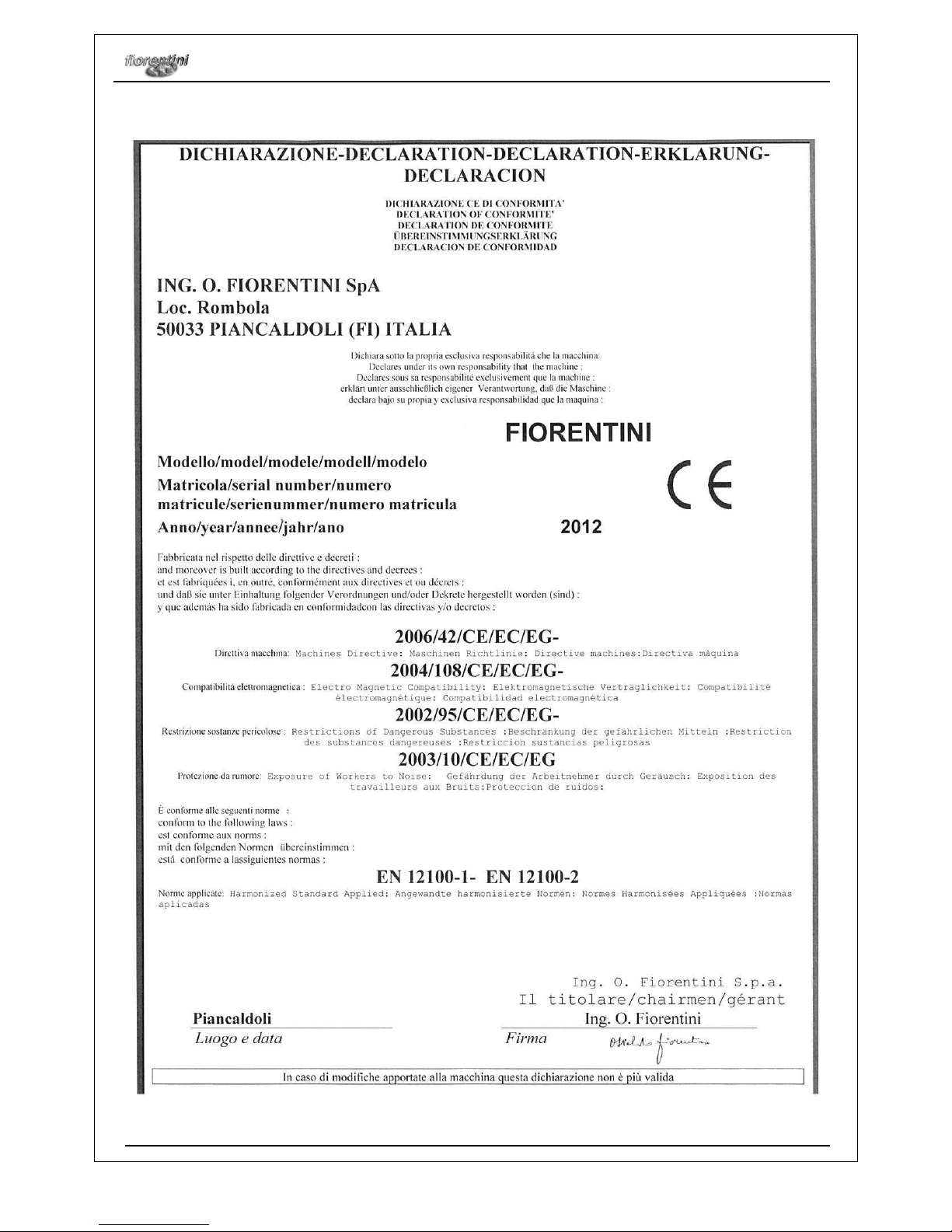
1.5. Conformity declaration…….........................................…...........………….…...……… 5
2. MACHINE FEATURES AND TECHNICAL DATA
2.3. Technical data………...................................…........……………………….....…..........
7
2.1. Identifying the machine……......…...............................….…………….….……........... 7
2.2. Description and components.……………...……………………………….…….…........
9
3. SAFETY
3.1. Right use of the machine……....……………....…....……………….......…………........ 10
3.2. Wrong use of the machine .……………………………………………….…..………….. 10
3.3. Suggested equipment……………………………………………………………………… 10
3.4. Operator qualify..............……………….......……………...…………............................ 11
3.5. Safety and warning devices ……………..................…...………….............................. 11
3.6. Safety systems...............................................…………..….…....…………......…........ 12
3.7. Safety diagnostic signaling ……………………………………………………………….. 12
3.8. Other dangers ……………………………………………………………………………… 15
3.9. Safety signals …………………………………………………………….………………... 16
4. STARTING AND USE INSTRUCTIONS
4.1. Trasport and handling……...................….....................…....……………….….…........ 18
4.2. Storage……………..............................................…………….…………….................. 19
4.3. How to unpack the machine...........................…………………….......................…..... 19
4.4. How to handle the unpacked machine.….…..........………………………..…….......... 19
4.5. Installation…...............................................................………………..…….…............. 20
4.5.1. Batteries installation……..........……..….......……………….…...….…….........…...... 20
4.5.2. Battery charger installation……………………………………………………………… 20
4.6. Control devices……………………………………………………………….…………….. 21
4.6.1. Dashboard………………………………………………………………………………… 21
4.7. Functioning………………………………………………………………………………….. 23
4.7.1. Preparing and starting the machine……………………………………………………. 23
4.7.2. Choosing the right detergent…………………………………..……………………….. 23
4.7.3. Functions levers …………………………………………………….…………………… 23
4.7.4. Squeegee adjustment ………………………………………………………………….. 24
4.7.5. Water drainage ……………..……………………………..……………………………. 26
4.7.6. Brushes replacement …………………………………………………………………… 27
4.7.7. Squeegee blades replacement…………………………………..…………………….. 28
Congratulations for your choice!
FIORENTINI S.p.A. thanking you for the preference to our product would like to remind
you that FIORENTINI’s S.p.A. production covers manufacture and marketing of industrial
cleaning machines and is currently a leading company in this sector.
Our tradition and competence guarantee technical quality of your choice; actually all our
products are being built first quality materials through criteria that can give reliability,
solidity and functionality satisfying every kind of customers. FIORENTINI has recently
obtained the quality system certificate conforming to the requirements of UNI EN ISO
9001:2000.
We wish therefore inviting you to contact us, unhesitatingly, for every kind of request, as
technical or commercial; we’ll be pleased to be at your disposal for any information you
may need.
5. MAINTENANCE
5.1. Periodical maintenance……………..……………..................….....…..……………….. 30
5.2. Batteries maintenance…………………………………………………………………….. 30
5.2.1. Hydrometrics.…………………………………………………………………………….. 31
5.2.2. Water filling up …………………………………………………………………………... 31
5.2.3. Charge limits……………………………………………………………………………… 31
5.2.4. Off duty or inactive batteries …………………………………………………………... 31
5.2.5. Battery charger technical features…………………………………………………….. 31
5.2.6. Batteries disposal………………………………………………………………………… 32
5.3. Suction motor maintenance……………………………………………………………….. 32
5.4. Electric equipment control………………………………………………………………... 34
5.5. Tests to be carried out…………………………………………………………………….. 34
5.6. Maintenance register………………………………………………………………………. 35
6. SERVICE
6.1. Service adresses............…………..................…………….......................................... 36
6.2. Claim report ……………………………..…………...………………….…...................... 36
GENERAL INFORMATION
Ecosmart
Rev. 000 29/11/2012
6/38
MACHINE FEATURES AND TECHNICAL DATA
Ecosmart
Rev. 000 29/11/2012
7/38
2.
MACHINE FEATURES AND TECHNICAL DATA
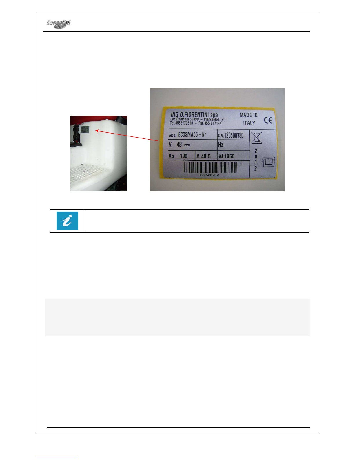
2.1. IDENTIFYING THE MACHINE
A silver label is sticked on the protection case of the steering column and clearly shows the data referring to
the “CE” marking.
The label has never to be removed and should always be kept readable. In case of
damage it is necessary to ask for a duplicate. The autoscrubber machine cannot be sold
without the label.
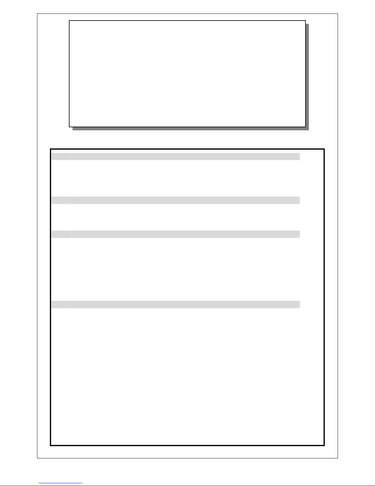
2.2. DESCRIPTION AND COMPONENTS
The scrubber machine Ecosmart has been designed for the cleaning of all flat surfaces by means of washing
and suction of the washing water.
The electric traction system is supplied by a series of batteries which supply energy to the brushes motors, to
the squeegee motor and to the suction motor..
The machine is equipped with two brushes or one brush which wash the surface by means of water and
detergent. Whilst the machine is running forward, the back brush (squeegee) picks the water up that is
directly sucked into the recovery tank.
By means of the ignition key (see part.8 Fig.4.6), the machine is prepared for the washing and drying of the
floor and with the forward preset; if ripreme returns to the initial situation..
The control panel controls all functions of the machine and provides a means of indicating to the operator,
through the use of LEDs and a display, provides a comprehensive overview of the activities' functioning
during washing. Through the control panel you can implement all the main functions of the machine. In
particular, you can:
start the washing machine in operation;
adjust the speed of advancement;
adjust the suction power;
determine the forward or backward;
display the battery charge;
lower the plate brushes and boot brushes;
start the vacuum;
turn on and off the machine;
PICTURE
N° 2.1
MACHINE FEATURES AND TECHNICAL DATA
Ecosmart
Rev. 000 29/11/2012
8/38
The structure of the machine consists of an iron frame with cataphoresis treatment and painting, so as to
avoid oxidation which could compromise the reliability of the machine itself.
The main components of the machine are:
Iron frame with cataphoresis and painting;
charging tank washing liquid plastic PPL;
recovery tank effluent washing plastic PPL with flexible suction piping system and drainage;
series of batteries placed in the solution tank room;
right rotating brush;
left rotating brush;
monobrush;
squeegee (suction system);
a motorized front wheel traction;
two idle wheels;
steering wheel;
driving seat .
FIORENTINI Co., taking the new CE safety rules into consideration, manufactures the machine following the
CE directives about safety and health. The materials high quality, the high technology and FIORENTINI’s
experience guarantee the performance and the reliability of this machine.
Each machine is tested during the manufacturing process and the final check is done before the machine is
shipped out.
MACHINE FEATURES AND TECHNICAL DATA
Ecosmart
Rev. 000 29/11/2012
9/38
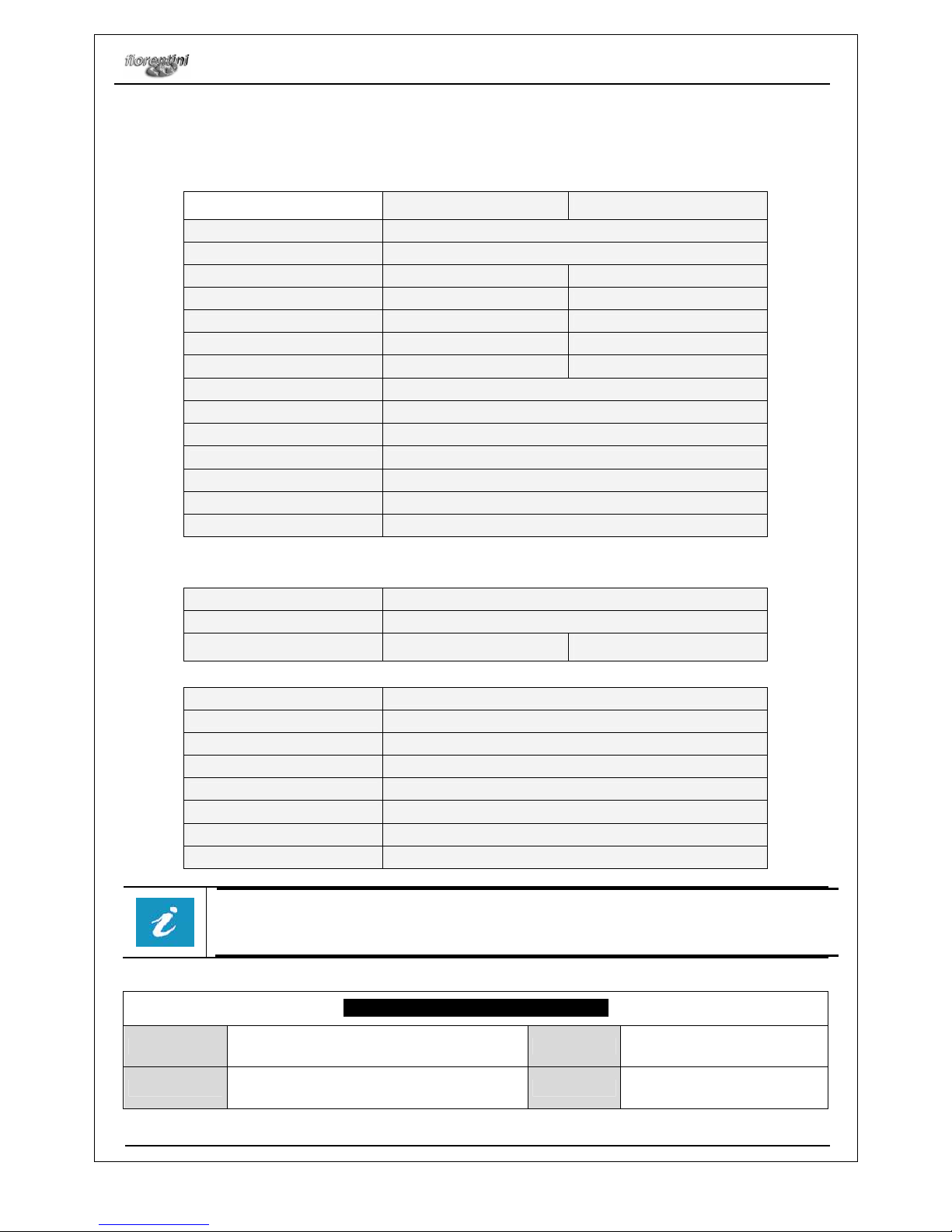
2.3. TECHNICAL DATA
SPECIFICATIONS
ECOSMART - 55 ECOSMART - 65
Alimentation
48 V (4 x 12 V – 85 Amp/h) (C5)
Drive system
Motor 48V 1x400W + Gear 1:25
Scrubbing width
540 mm 680 mm
Squeegee width
775 mm 870 mm
No. brushes
N°1 Ø 540 mm N°2 Ø 350 mm
Pressure brushes
31 kg 31 kg
Working capacity up to
3200 mq/h 4000 mq/h
Autonomy of work for normal use
3,5 h
Autonomy silent working
4 h
Autonomy work hard floors
3 h
Solution tank
105 liters
Recovery tank
115 liters
Water lift
170 mBar
Forward speed
3 - 4 - 5 - 6 Km/h
CARATTERISTICHE TECNICHE MOTORI
Traction motor
48 V - 400 W
Suction motor
48 V 300 – 500 - 750 W
Brush motor
N°1 400 W
- 8.3 A -
48 V -
130 rpm
N°2 400 W
- 8.3 A -
48 V -
130
rpm
DIMENSIONI
Length
1186 mm
Width
580 mm
Height
1220 mm
Weight without batteries
130 kg
Drive
Man on board
Corridor minimum U-turn
1520 mm
Max. gradient at full load
10 %
Noise level
58 dB(A)
The above mentioned characteristics are not binding for the manufacturer; they can be
changed without any notice. ING.O.FIORENTINI Co. is always at disposal for any
information.
MEASUREMENT UNITS CONVERSION
Lenght
1 inch = 1” = 25,4 mm
Power
1 kW = 1,36 CV = 1,34 BHP
Temperature
T (K) = t (°C) + 273 / t (°F) = 1,8 t (°C) + 32
Pressure
1 bar =100 kPa = 14,5 psi
SAFETY
Ecosmart
Rev. 000 29/11/2012
10/38
3. SAFETY
3.1. RIGHT USE OF THE MACHINE
This machine is a scrubbing machine and it has been designed and built to clean in
an industrial place. It can work on flat surfaces or on sloping surfaces not higher
than 10% and with a speed not higher than 3 km/h while the machine is reversing. It
may not make a U on any slope gradient.
3.2. WRONG USE OF THE MACHINE
The machine cannot be driven by non-authorized personnel;
The machine cannot wash sloping surfaces whose gradient is higher than 10% or
surfaces with holes;
The machine cannot be used in places with dangerous substances and in particular
with explosive atmospheres or with a bad microclimate;
The machine cannot clean surfaces with inflammable products;
The machine cannot be used as a means of transport for people or other means of
transport;
The protection devices of the machine cannot be modified or tampered;
Batteries must be recharged in a fanned room;
The operator have always to respect safety rules;
The operator cannot use equipments or devices that can create problems to the
machine working;
The machine components cannot be modified without FIORENTINI’s authorization;
The operator cannot use acids that can damage the machine;
The operator has always to respect the rules written in the user manual.
Please read carefully and do not cover the labels sticked on the machine. FIORENTINI
S.p.A. is not responsible for a wrong use of the machine.
3.3. SUGGESTED EQUIPMENT
In order to use the machine in a proper way, we suggest to use the FIORENTINI’s equipment and original
spare parts.
FIORENTINI S.p.A. Technical Dept. is always at your disposal to design components or parts for a particular
use of machine as requested by the customer.
SAFETY
Ecosmart
Rev. 000 29/11/2012
11/38
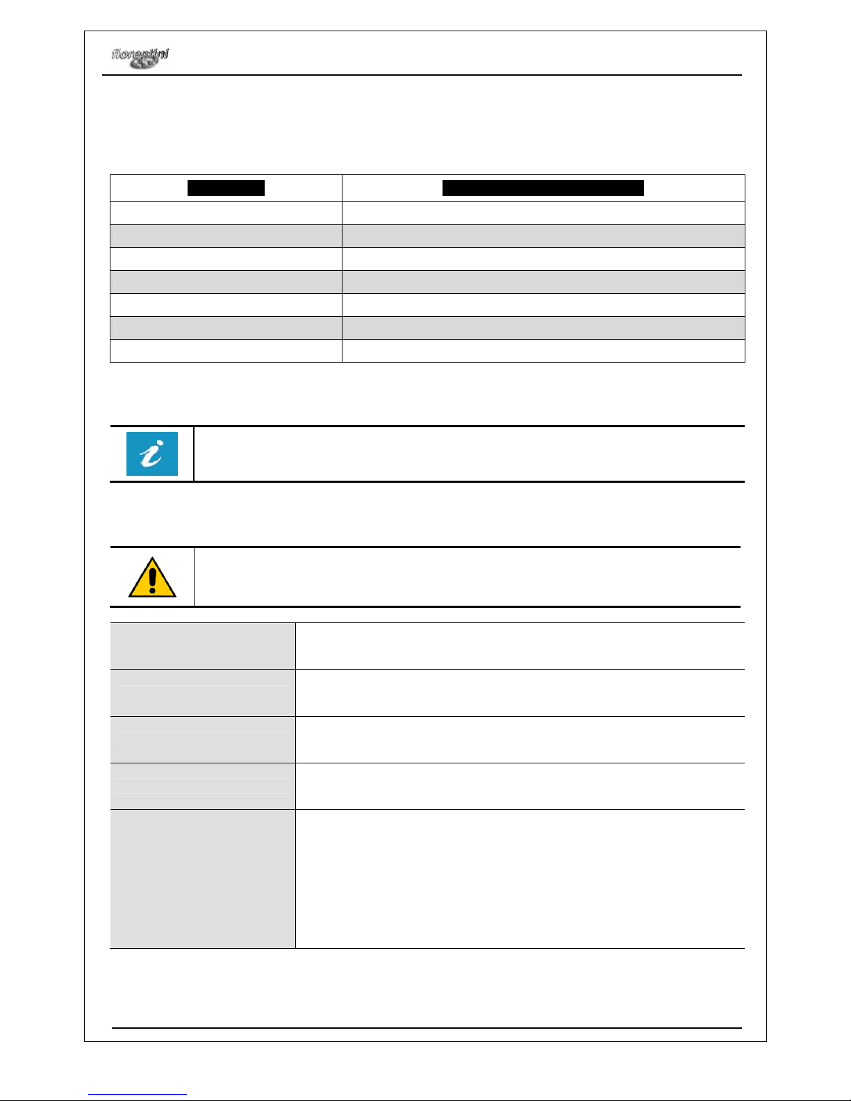
3.4. OPERATOR’S QUALIFICATIONS
The scheme below sumarizes the operator’s qualifications requested for each kind of operation.
OPERATION
OPERATOR’S QUALIFICATIONS
Driving/control of the machine
Trained operator
Installation/ disinstallation Fiorentini technician
Mechanical parts maintenance
Fiorentini technician
Electric parts maintenance
Fiorentini technician
Cleaning maintenance
Trained operator
Dismantling and demolition
Fiorentini technician
FIORENTINI S.p.A. suggests to train the operator before using the machine. The operator also must be
trained about safety rules and carefully read this manual.
FIORENTINI S.p.A. is not responsible for any possible damage to people and/or things caused by
the non-observance of the instructions dealt within this manual.
3.5. SAFETY AND WARNING DEVICES
• It is absolutely forbidden to tamper or disconnect safety and warning devices while
the machine is working;
• It is important to check periodically safety and warning devices (see § 5.1.).
Emergency seat switch
This machine is equipped with an emergency switch under the driving seat.
It avoids that the machine starts when the operator is not on board.
Floating timer
The machine is equipped with a timer for the float that avoids the switching
on and off of the vacuum motor
Filter
The machine is equipped with a foam filter
Solenoid valve
The machine is equipped with a solenoid valve which prevents the escape
of the water does not take place until the ignition of the brushes. (Optional)
Warning devices
Ecosmart is equipped with several warning devices:
One acoustic warning device like a claxon. It has to warn people who
are near the machine while its operating;
One intermittent bleeper to warn people while the machine is
reversing;
A signal light with a yellow flashing light to signal the machine in
operation.(Optional)
SAFETY
Ecosmart
Rev. 000 29/11/2012
12/38
3.6 SAFETY SYSTEMS
The machine is equipped with the following safety systems:
Socket (picture 4.5), the same socket used for the battery charger. In case of emergency, this
socket must be taken away from the plug by means of its handle.
The operator must be trained about safety rules. Do never restore this safety system before the
problem has been sorted out. If it is necessary ask for the technician help.
Emergency seat switch: The machine is equipped with presence sensor inserted in the seat. No
operator on board, the car will not start, also if the operator falls from the cleaning machine without
having turned to position 0, the key switch, the machine shuts down. To turn it back up on the seat,
turn the key switch in the OFF position, wait a few seconds then return the key switch in the ON
position.
Float: The recovery tank is equipped with a float which blocks the suction in the case of overfilling
warning the operator through a sound effect; in this case to restart the machine must first empty the
tank.
Solenoid valve (optional): The machine is equipped with a solenoid valve which makes the water
to pass only at power of the brushes so avoiding the accidental leakage.
Floating timer: The machine is equipped with a timer on the float of dirty water that causes the
oscillation of the water prevents the switching on and off of the engine intake.
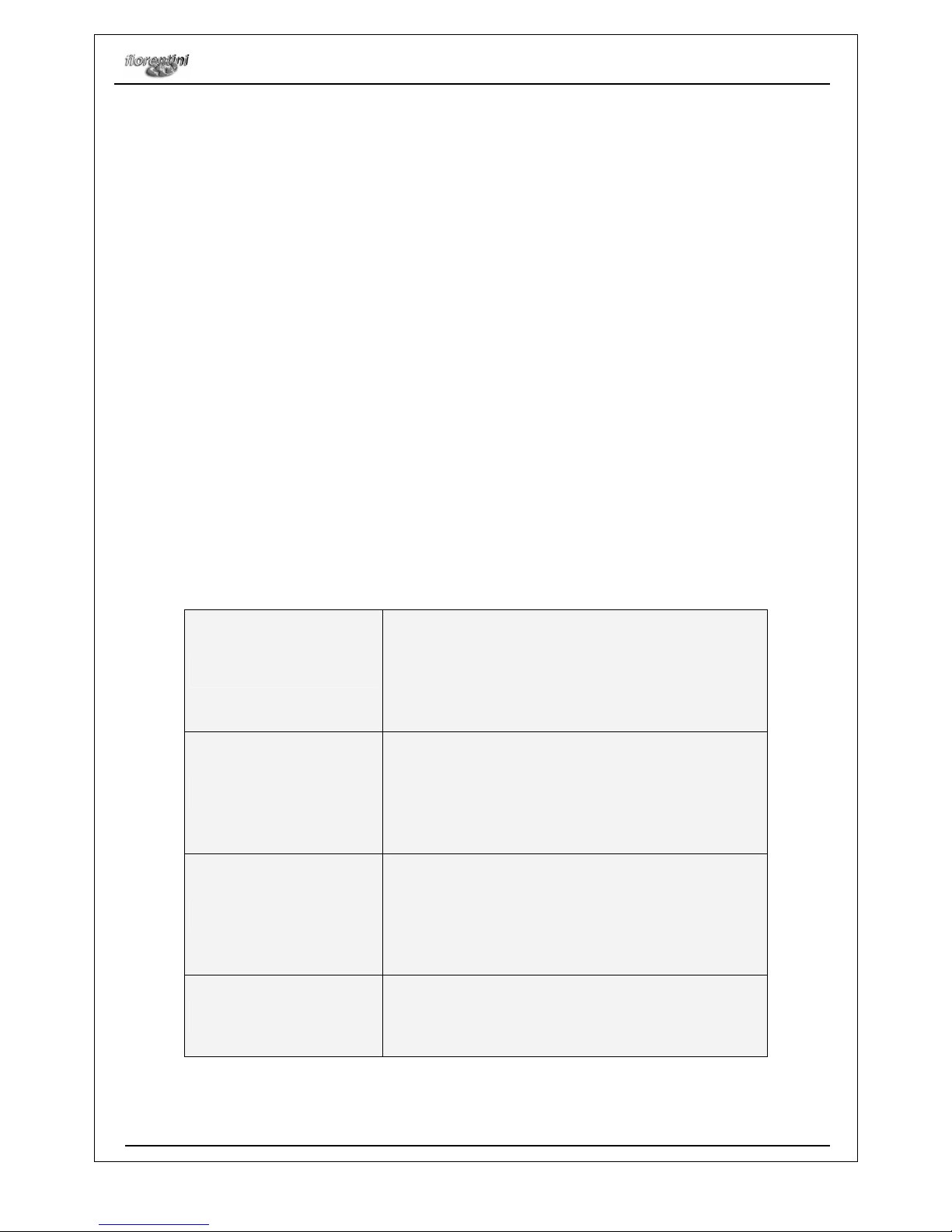
3.7 SAFETY DIAGNOSTIC SIGNALING
The cleaning machine is equipped with a system for which all the errors detected by the electronic board that
controls the functions of the machine appear on the display which is located on the dashboard of the
machine. For every comment 'associated with a description of the error received by the board.
01 SUCTION BLOCK
Intervenes to protect from short
-
circuiting. The value of absorbed
current is too high. The machine is blocked.
Reset on start-up. Once restarted the electronics display all the
default values: all the utilities are off, the speed adjustments are
set to the value chosen by parameter, the jacks are lifted, no
consent for operation. The error is re-proposed only if suction is
started and absorption is anomalous. Therefore until suction starts
the rest of the machine functions normally.
02 BRUSHES BLOCK
Intervenes to protect from short
-
circuiting. The value of absorbed
current is too high. The machine is blocked.
Reset on start-up. Once restarted the electronics display all the
default values: all the utilities are off, the speed adjustments are
set to the value chosen by parameter, the jacks are lifted, no
consent for operation. The error is re-proposed only if the brushes
are started and absorption is anomalous. Therefore until the
brushes start the rest of the machine functions normally.
03 TRACTION BLOCK
Intervenes to protect from short
-
circuiting. The value of absorbed
current is too high. The machine is blocked.
Reset on start-up. Once restarted the electronics display all the
default values: all the utilities are off, the speed adjustments are
set to the value chosen by parameter, the jacks are lifted, no
consent for operation. The error is re-proposed only if traction is
started and absorption is anomalous. Therefore until the traction
starts the rest of the machine functions normally.
04 MAX. ELECTRONIC TEMP.
The temp.
of the card reaches the max. value set by parameter.
The
entire machine does not work.
If the temp. goes below a certain value set by the parameter
(hysteresis) the error disappears and the machine starts working
normally again.
 Loading...