

Page 1
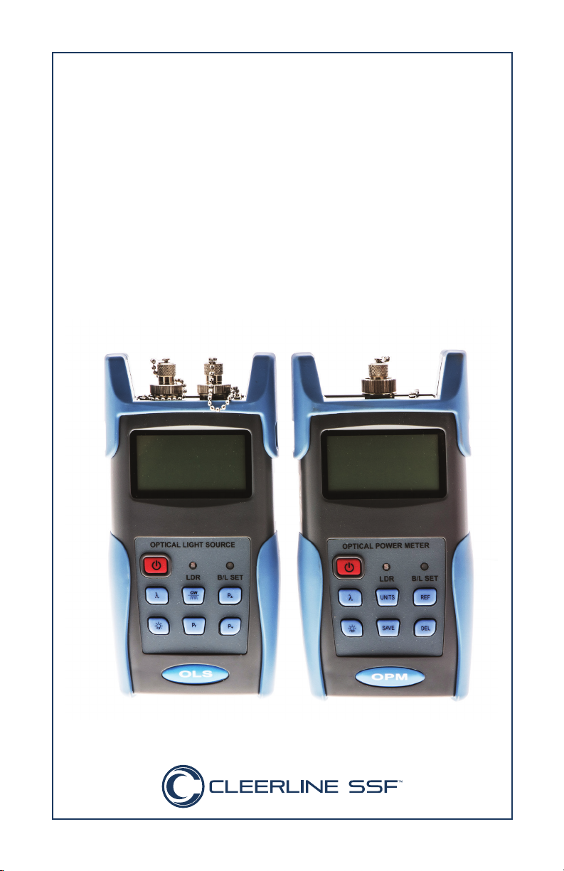
SSF-TKITP-400
SSF™ Pro Fiber Test Kit
Manual
Page 2

Contents
Handheld Light Source
Overview 3
Features 3
Accessories 3
Specifications 4
Functions 5
Powering the Light Source 8
Power Supply Options 8
AA Battery 8
Replacing Batteries 8
Power Supply Unit 9
Turning the Light Source On or Off 10
Turning the Light Source On 10
Auto Shutdown Function 10
Turning the Light Source Off 10
Backlight Control 11
LDR: Intelligent Backlight Control Mode 11
Key Control Mode 11
Changing Backlight Mode 11
Laser Settings 12
Activating the Laser 12
Selecting Wavelength 12
Selecting Frequency 13
Output Power 14
Automatic Wavelength Identification 15
Automatic Frequency Detection 16
Maintenance and Troubleshooting 17
Troubleshooting 17
Warranty 18
WARNING
To avoid the risk of serious eye damage, do not look into the
laser at any time.
1
Page 3

Handheld Power Meter
Overview 20
Features 20
Accessories 20
Specifications 21
Functions 22
Powering the Meter 25
Power Supply Options 25
AA Battery 25
Replacing Batteries 25
Power Supply Unit 26
Connecting Cables 27
Connecting USB Cable 27
Connecting Patch Cable 27
Turning the Power Meter On or Off 28
Turning the Power Meter On 28
Auto Shutdown Function 28
Turning the Power Meter Off 28
Backlight Control 29
LDR: Intelligent Backlight Control Mode 29
Key Control Mode 29
Changing Backlight Mode 29
Wavelength 30
Calibrating Wavelength 30
Automatic Wavelength Detection 30
Automatic Wavelength Identification Configuration 31
Automatic Frequency Detection 32
Choosing Units 33
Setting Reference Value 34
Managing Data Records 35
Saving Records 35
Viewing and Deleting Records 35
Downloading and Installing Software 36
Software Set-Up 37
Connecting the Power Meter 37
Using Test Kit Software 39
Maintenance and Troubleshooting 40
Troubleshooting 40
Warranty 41
2
Page 4

Handheld Optical Light Source
Overview
This handheld optical light source is designed for fiber optic network
installation, evaluation, and maintenance. Used with its matched
optical power meter, it provides an accurate fiber network testing
solution. This light source can provide 1-4 wavelengths with stable
output power and features continuous adjustable output power. The
intelligent backlight control function reduces power usage. The optical light source has a rugged appearance and comfortable design to
clients’ requirements.
Features
• Wave ID information can be transmitted when used with the
matched optical power meter.
• Tone generation: 270HZ, 330HZ, 1KHZ, 2KHZ
• Adjustable output power
• Output power value shown on LCD display
• Intelligent backlight control (light intensity can be adjusted
according to ambient light, greatly reducing power
consumption)
• AA alkaline batteries and AC adapter for power supply
• Low battery indicator
Accessories
(1) Operation Manual
(1) Cleaning Swabs
(3) 1.5V AA battery
(1) AC Power Supply Adapter
(1) Carrying Case
3
Page 5
Handheld Optical Light Source
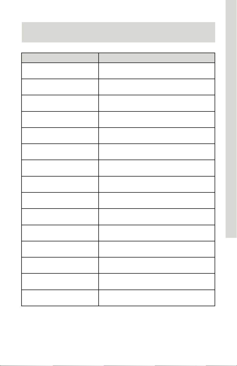
Specifications
Model Optical Light Source
Operating wavelength (nm) 850/1300/1310/1550
Applicable fiber SM, MM
Laser type FP-LD
Maximum Output Power
(dBm)
Adjustable step size (dBm) < 0.5 (adjustable between -5-12dBm)
Stability (dB, 15min, 20°C) ±0.1
Stability (dB, 30min, 20°C) ±0.05
Modulation (Hz) CW, 270, 330,1K, 2K
Fiber Port FC/PC or FC, SC, ST interchangeable
Alkaline Battery 3*AA,1.5V
Power Supply Adapter (V) 8.4
Battery Operating time (h) 45
Operation Temperature (°C) -10 - +60
Storage Temperature (°C) -25 - +70
-5 (adjustable)
Dimensions (mm) / Weight 175x90x44.5 / 255g
4
Page 6
Handheld Optical Light Source
Functions
9
1
2
3
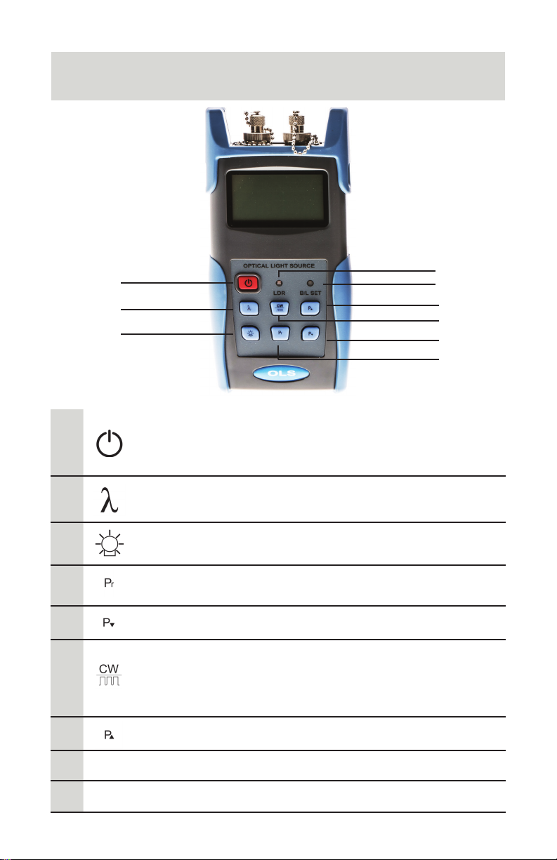
Power On/Off: Press to turn the unit on or off.
1
Auto Shut-Off Selection: Press this key quickly to turn
the auto shut-off function on or off.
8
7
6
5
4
2
3
4
5
6
7
B/L Set
8
LDR
9
Wavelength Selection: Press to activate laser and
select wavelength.
Backlight control: Press to select LDR (intelligent
backlight control) or backlight key mode.
Rated power: Select default output power (dBM)
(maximum value) for wavelength in use
Decrease: Press to decrease the rated output power
Frequency modulation / Wavelength identification:
Press quickly to adjust the frequency.
Press and hold to enter/exit wavelength identification
mode.
Increase: Press to increase the output power
Backlight indicator
Intelligent backlight control sensor
5
Page 7
Handheld Optical Light Source
2A 2B
1
2
5
3
4
Back/Side
1
2
3
4
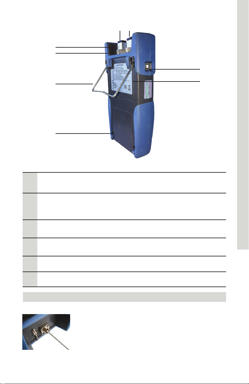
Dust Cap: Place the dust cap over the connectors to
protect the optical connector when not in use
Optical Connector: SC/PC optical connector.
2A: Port 1: 1310/1550nm Output
2B: Port 2: 850/1300nm Output
Bracket: Collapsible metal bracket can be adjusted
0-90 degrees
Battery Pack:
Contains 3 x 1.5 AA Batteries
6
5
6
Label: Basic function and instruction information
AC Adapter Port: Connect AC adapter
Note
Small amounts of dust on the connector will
affect the accuracy of the measurement. Use
isopropyl alcohol and a cotton swab to clean the
connector. Moisten the cotton swab with alcohol,
insert the cotton swab in the connector, slightly
rotating the cotton swab. Always dry using a
second dry cotton swab.
6
Page 8
Handheld Optical Light Source
1
2
4
3
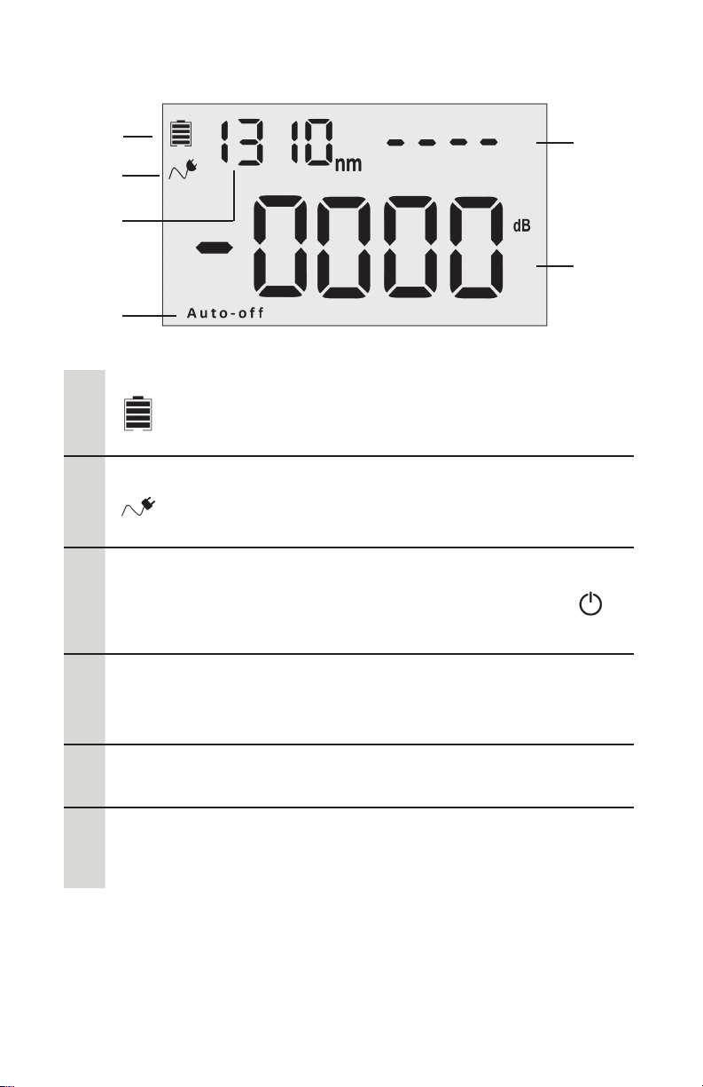
Screen
Battery Indicator: displays when battery power in use.
1
2
Auto-o
3
The capacity shown will decrease with battery power.
Replace batteries as needed.
AC Adapter Indicator: displays when AC power in use
Auto-off: the light source will automatically shut off
when idle for ten minutes. Press power button ( )
quickly to turn Auto-Off function on or off.
5
6
Wavelength: (nm)
4
nm
5
6
Modulated Frequency: (Hz)
Dashed line indicates laser is off.
Output Power Value: (dBm)
850/1300: Multimode fiber testing
1310/1550: Single mode fiber testing
7
Page 9
Handheld Optical Light Source
Powering the Light Source
Power Supply Options
The light source can be powered by either battery or AC adapter
power, allowing total flexibility for most testing sites and situations.
AA Battery
When batteries are in use, will display on the top left of the
screen (Screen, page 7).
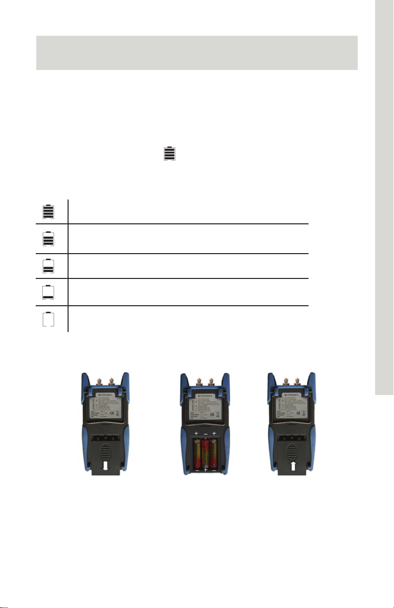
There are five levels of battery power:
70%-100% power
40%-70% power
20%-40% power
Less than 20%. The power meter will shut down.
Replace batteries
Replacing Batteries
1. Push the clip fastener on the battery compartment cover down.
2. Remove the battery compartment cover and remove all three
batteries, noting their positive and negative orientation. The
negative battery connector should be against the spring.
3. Insert 3 new 1.5VV AA batteries. Be sure to align correctly.
4. Refit the battery compartment cover. The clip fastener should
click shut.
8
Page 10
Handheld Optical Light Source
Power Supply Unit
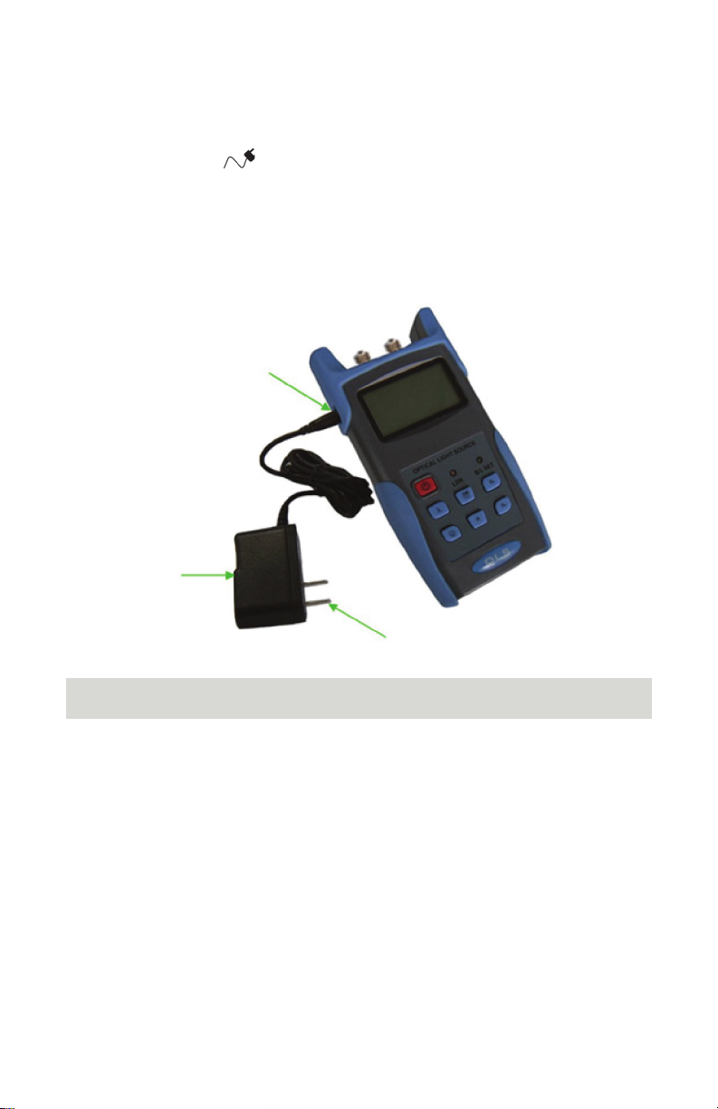
AC power can be used when the batteries are empty. The AC
adapter indicator,
, will display on the left of the screen when AC
power is in use (Screen, page 7). The light source will default to AC
power supply if charged batteries are present in the unit when it is
plugged in.
When using the AC adapter, connect the power plug (pictured) and
insert it into the AC adapter port
AC Adapter Port
Note
Only use the power supply unit supplied with the tester. Using
another type of power supply may damage the instrument.
9
Page 11
Handheld Optical Light Source
Turning the Light Source On or Off
Turning the Light Source On
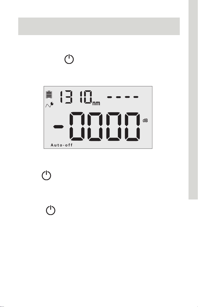
1. Insert the battery or connect the power supply unit.
2. Press and hold
activate the laser.
3. The screen display will show a dashed line in the upper right
corner.
on the tester. Note that this does not
See page 7 for screen details
Auto Shutdown Function
Press the key to enable or disable the auto shutdown function.
When selected, “Auto-Off” will appear at the bottom of the screen.
The light source will shut down automatically after 10 minutes idle.
Turning the Light Source Off
Hold down to turn off the light source.
10
Page 12
Handheld Optical Light Source
Backlight Control
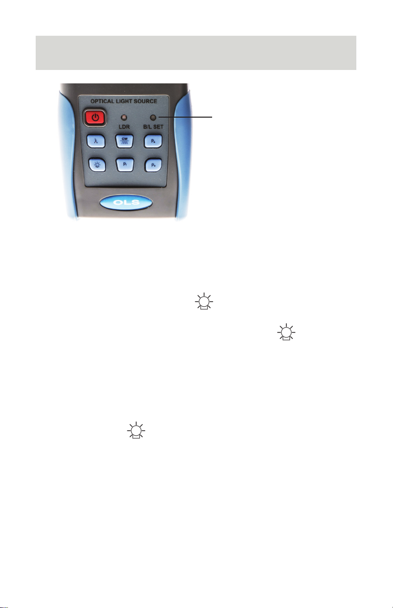
B/L SET
1. Green when LDR activates
2. Red when Key Control
Mode activates
LDR: Intelligent Backlight Control Mode
In LDR, the light source will automatically adjust the backlight to
ambient light within 15 seconds.
Key Control Mode
In key control mode, pressing the key turns the backlight on or
off.
1. With light source turned on, press and hold the key.
2. The BL/SET light will turn red. (Fig X)
3. After 10 seconds, the indicator light will turn off. Key control
mode is active.
Changing Backlight Mode
Press and hold the key to switch from one backlight mode to
the other. Green B/L Set light indicates the LDR is active.
11
Page 13
Handheld Optical Light Source
Laser Settings
Note
1. A warm-up period of 5 minutes or less is normally required to
ensure stable output power.
2. Ensure that connectors and patch cable ends are clean before
attaching. Be sure to connect the correct type of patch cable.
3. To avoid the risk of serious eye damage, do not look into the
laser at any time.
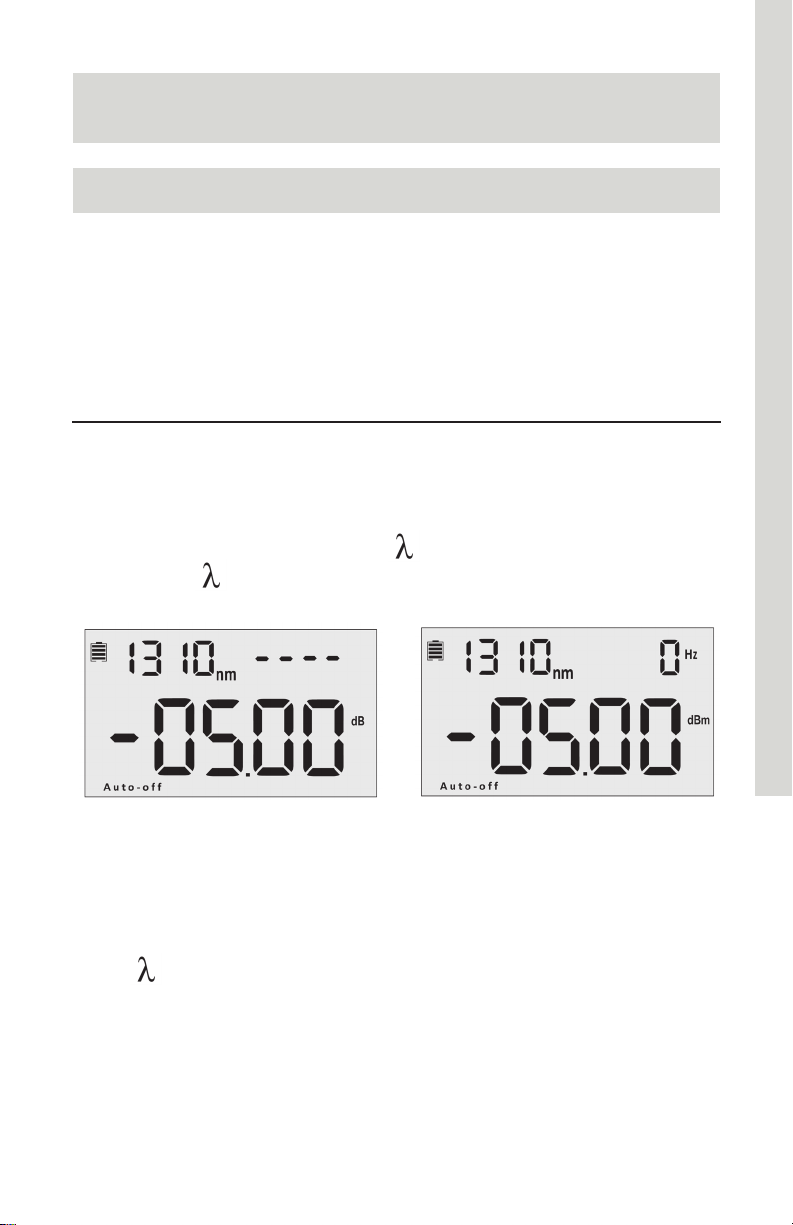
Activating the Laser
1. Remove dust cap and connect patch cable.
2. When the light source is first powered on, the laser will not be
active. Press the wavelength (
) key to activate the laser.
3. Pressing
will set the initial frequency to 0Hz.
Laser Off Laser On
Wavelength: 1310nm
Frequency: 0Hz
Rated Output Power: -5.00 dBM
Selecting Wavelength
Press to select the output wavelength (nm) displayed at top left
of screen.
Available wavelengths are 850nm, 1300nm (multimode testing) and
1310nm, 1550nm (single mode testing).
12
Page 14
Handheld Optical Light Source
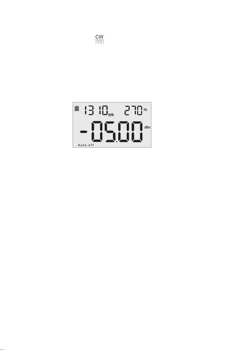
Selecting Frequency
When laser is active, press to adjust the frequency (Hz). The
value is displayed in the top right corner of the screen.
Available frequencies are 0Hz (continuous wave), 270Hz, 330Hz,
1000Hz, and 2000Hz.
When the laser is off, pressing and holding this key twice in
succession will activate the laser.
Frequency is displayed at
the top right of the screen
The matching power meter can be configured to identify the
frequency set on the light source, see Automatic Frequency
Detection.
13
Page 15
Handheld Optical Light Source
Output Power
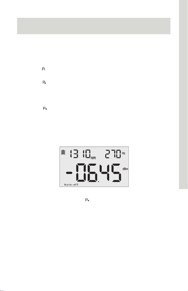
Each available wavelength setting allows the output power (laser
light intensity) to be adjusted within the range of approximately -5 to
-12 dBm.
1. Press
selected wavelength.
2. Press
available already appears on screen, this key will return the light
source to the minimum dBm output for the wavelength and then
increase the output.
3. Press
available already appears on screen, this key will return the light
source to the maximum dBm output for the wavelength and
then decrease the output.
to select the maximum output power available for the
to increase the output power. If maximum value
to decrease the output power. If minimum value
In this image, has been pushed to
decrease the output power shown on
page 12.
14
Page 16
Handheld Optical Light Source
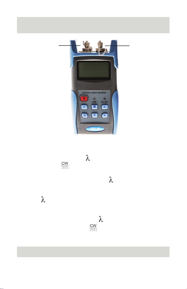
Automatic Wavelength Identification
850nm
1300nm
Light Source
1. Connect the light source to its matched optical power meter
2. On the light source, press
3. Press and hold
of the screen. This indicates that Wave ID mode is active.
4. On the power meter, press and hold
the upper right corner of the screen. Wave ID mode is now
active.
5. Press
After 3-5 seconds, the power meter will update to match the
wavelength
6. To exit Wave ID, press and hold
to change wavelength on light source as desired.
until --AU appears on the upper right corner
to activate laser.
until --AU appears on
on the power meter. On the
1310nm
1550nm
light source, press and hold
(0Hz).
Wave ID Mode and Auto Frequency Detection cannot operate
at the same time.
to return to continuous wave
Note
15
Page 17
Handheld Optical Light Source
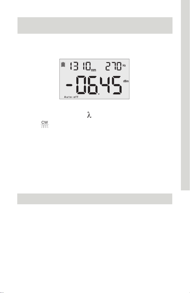
Automatic Frequency Detection
Automatic Frequency Detection will operate by default when
Automatic Wavelength Identification mode is not in use.
1. Connect the light source to its match power meter.
2. On the light source, press
3. Press
1KHz, or 2KHz). This will display on the upper right of the
screen.
4. The optical power meter will detect the frequency automatically
and display it on the upper right corner of its screen.
Wave ID Mode and Auto Frequency Detection cannot operate
at the same time.
to select modulation frequency (270Hz, 330Hz,
to activate laser.
Note
16
Page 18

Handheld Optical Light Source
Maintenance and Troubleshooting
1. Always keep the connector ports of the light source clean.
2. Use the regulated optical connector for testing.
3. Shut off the power and cover laser with dust-proof cap after use.
4. When using AC adapter, ensure power supply is within the
required voltage range.
5. Remove the batteries when light source not in use for extended
periods of time.
Troubleshooting
Issue Possible Reason Solution
Faint screen display Low battery power
Low battery power
Unit fails to turn on
Optical power is not
stable after when
light source turned
on
or battery inserted
incorrectly
Charge or replace
the battery.
(A) Replace the
battery
(B) Re-insert the
battery
Allow a 15 minute
warm-up period
Warning
1. Ensure the connector is clean before testing.
2. Only use the supplied adapter.
3. Do not look into the laser when unit is on.
4. Charge the batteries before use. Do not charge in unit.
5. Cover laser with dust-proof cap when not in operation.
6. Clean the optical port of the power meter regularly.
17
Page 19

Handheld Optical Light Source
Warranty
Caution: Do not attempt to repair as doing so will void warranty.
This Optical Power Meter is covered by an 18 month warranty
1. We warrant that this power meter will be free from defects in
material and workmanship for 18 months. Should the device
fail at any time during this warranty period, we will, at our sole
discretion, replace and repair or refund the purchase price of
the product. The worth of the repair or replacement will not be
higher than purchasing price of this unit.
2. If device issues cannot be solved by the troubleshooting
methods, please contact us or the local distributor directly.
3. We will repair or replace the unit free of charge in case of defects
in production, workmanship or material. This warranty only
applies to the unit under normal operation without any damage
or misuse/abuse.
4. The shipping costs incurred by repair or replacement for the unit
under warranty will be shared by both parties.
18
Page 20

Handheld Optical Power Meter
SSF-TKITP-400 Power Meter
19
Page 21

Handheld Optical Power Meter
Overview
The Cleerline SSF™ Optical Power Meter is a newly designed fiber
optic tester intended for the installation, engineering evaluation, and
maintenance of fiber networks.
Compared with other power meters, the TKITP-400 Power Meter
has more functions, including automatic wavelength identification,
auto wavelength switching, intelligent backlight, and data saving via
USB port.
Combined with its matched handheld optical light source, it offers
a quick and accurate testing solution on both single mode and
multimode fibers.
Features
• Wave ID: auto wavelength identification & switching
• Frequency ID: auto frequency identification
• Manual and automatic (ambient light sensing) backlight
control modes
• Storage of up to 1000 data records, downloadable via USB
cable
• Mini USB port for downloading and saving testing records
• Adjustable/storable reference power level
• User self-calibration function
• Auto shutdown function
• Up to 200 hours battery life
Accessories
(1) Operation Manual
(1) USB Cable
(3) 1.5V AA battery
(1) AC Power Supply Adapter
(1) Cotton cleaning swab
20
Page 22

Handheld Optical Power Meter
Specifications
Model A C
Calibration Wavelength (nm) 850/1300/1310/1490/1550/1625
Detector type InGaAs
Measurement Range (dBm) -70 - +6 -50 -+26
Uncertainty (dB) ±0.15 (3.5%)
Linearity (dB) ±0.02
Display resolution (dB) 0.01
Frequency ID (Hz) 270, 330,1K, 2K
Wave ID (nm) 850,1300, 1310, 1490, 1550, 1625
Date Storage Capacity 1000
Communication Port USB
Standard Connector FC /2.5mm universal
Optional Optical Connector SC/FC Type
Optional Optical Connector None
Alkaline battery 3*AA, 1.5V
Power Adapter (V) 8.4
Battery Operating time (h) 200 without backlight*
Operation Temperature (°C) -10 - +60
Storage Temperature (°C) -25 - +70
Dimension (mm) 175x90x44.5
Weight (g) 231
* Continuous backlight operation will shorten battery life
21
Page 23
Handheld Optical Power Meter
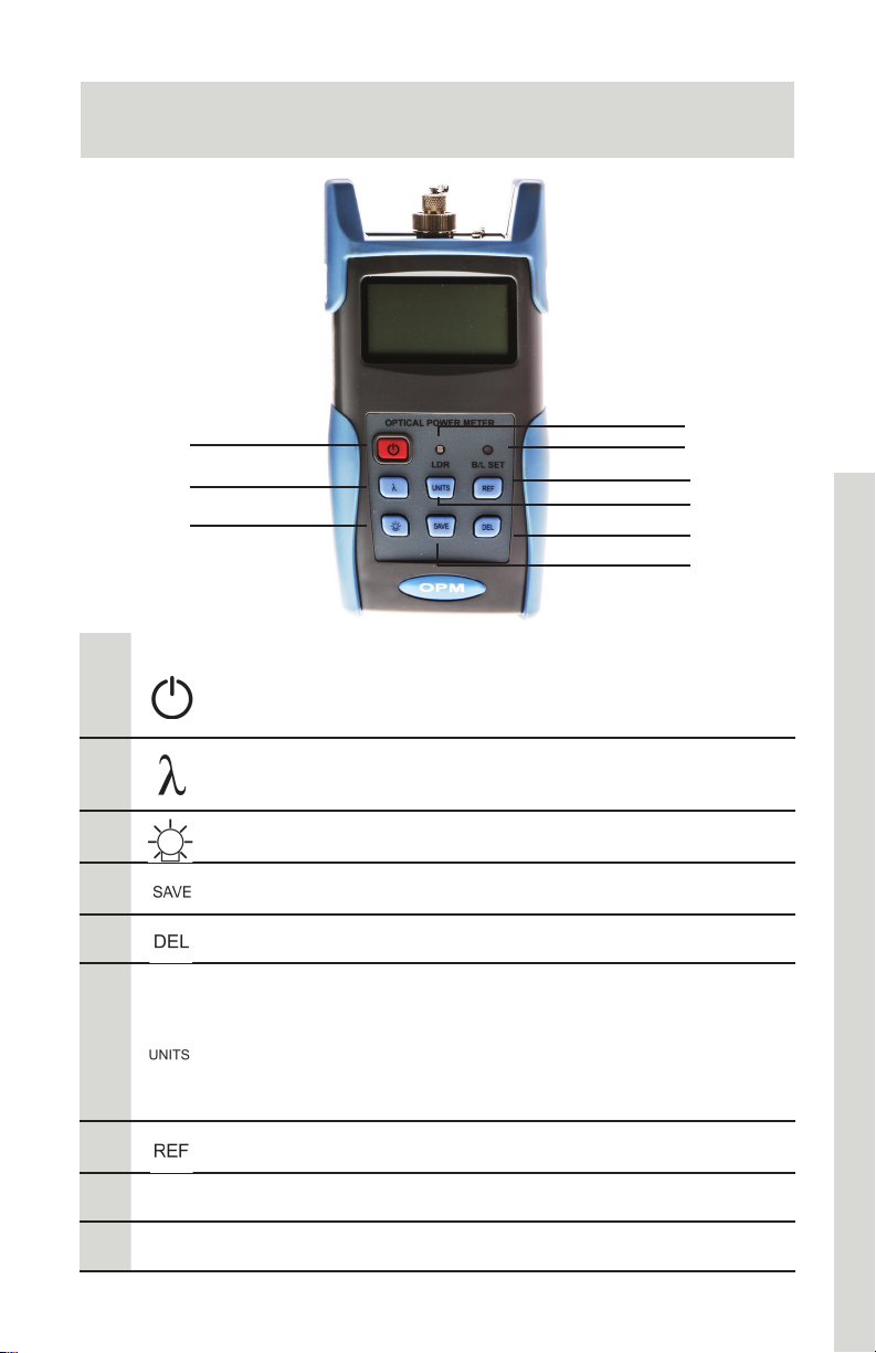
Functions
9
1
2
3
Power On/Off: Press and hold to turn the unit on or off.
1
Auto Shut-Off Selection: Press this key quickly to turn
the auto shut-off function on or off.
8
7
6
5
4
2
3
4
5
6
7
B/L Set
8
LDR
9
Wavelength Selection: Press to select wavelength.
Press and hold to enter Wavelength Auto-ID mode.
Backlight control: Press to select backlight mode.
Save/View: Display data records and save new.
Delete: Cancel or delete saved records
Unit Selection: Press to select units
dBM: Optical power measurement (absolute)
dB: Relative (loss) measurement
mW, uW, nW: Power- milliwatts, microwatts, or
nanowatts
Reference: Set current power value (dBM) as reference
Backlight indicator
Intelligent backlight control sensor
22
Page 24
Handheld Optical Power Meter
1
2
3 (side)
4
5
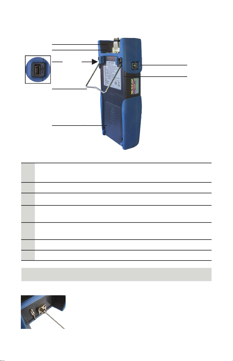
Back/Sides
1
2
3
4
5
6
7
Dust Cap: Place the dust cap over the connectors to
protect the optical connector when not in use
Optical Connector: SC (Φ2.5mm) optical connector.
Mini USB Port: Connect USB cable
Bracket: Collapsible metal bracket can be adjusted
0-90 degrees
Battery Pack:
Contains 3 x 1.5 AA Batteries
Label: Basic function and instruction information
AC Adapter Port: Connect AC adapter
7
6
Note
Small amounts of dust on the connector will
affect the accuracy of the measurement. Use
isopropyl alcohol and a cotton swab to clean the
connector. Moisten the cotton swab with alcohol,
insert the cotton swab in the connector, slightly
rotating the cotton swab. Dry using a second
dry cotton swab.
23
Page 25
Handheld Optical Power Meter
1
2
4
3
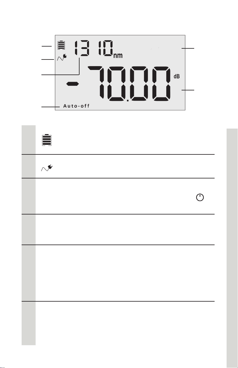
Screen
Battery Indicator: displays when battery power in use.
1
2
Auto-o
3
The capacity shown will decrease with battery power.
Replace batteries as needed.
AC Adapter Indicator: displays when AC power in use
Auto-off: the power meter will automatically shut off
when idle for ten minutes. Press power button ( )
quickly to turn Auto-Off function on or off.
Wavelength: (nm)
5
6
4
nm
5
6
850/1300: Multimode fiber testing
1310/1550: Single mode fiber testing
Various: Depending on settings, this area will display
a. --AU: Automatic Wavelength mode active
b. Data record number
c. Power reference value (dBM)
d. Frequency (Hz) determined by light source
settings
Output Power and Relative Measurement: Depending
on settings, the power meter will display dBM
(absolute power measurement), relative measurement
used for loss (dB), or xW (mW, uW, nW) value.
24
Page 26
Handheld Optical Power Meter
Powering the Meter
Power Supply Options
The power meter can be powered by either battery or AC adapter
power, allowing total flexibility for most testing sites and situations.
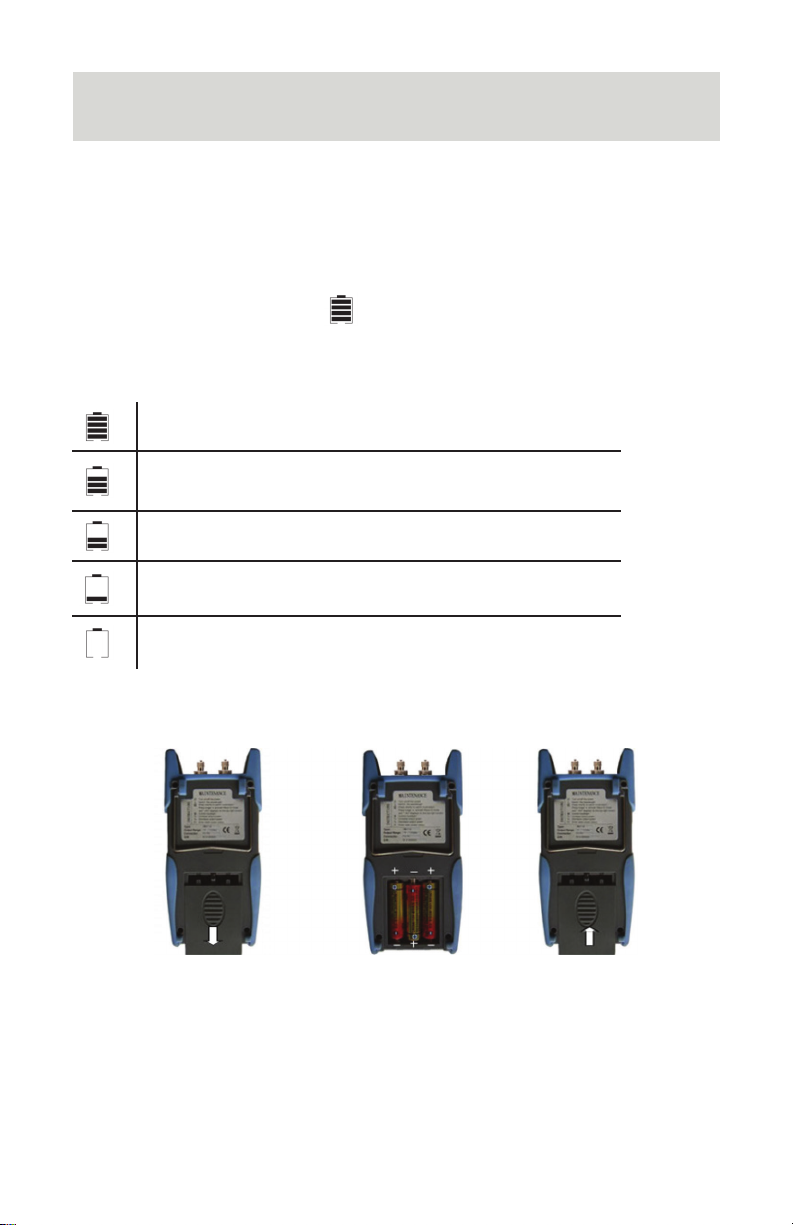
AA Battery
When batteries are in use, will display on the top left of the
screen (Screen, page 24).
There are five levels of battery power:
70%-100% power
40%-70% power
20%-40% power
Less than 20%. The power meter will shut down.
Replace batteries
Replacing Batteries
1. Push the clip fastener on the battery compartment cover down.
2. Remove the battery compartment cover and remove all three
batteries, noting their positive and negative orientation. The
negative battery connector should be against the spring.
3. Insert 3 new 1.5VV AA batteries. Be sure to align correctly.
4. Refit the battery compartment cover. The clip fastener should
click shut.
25
Page 27
Handheld Optical Power Meter
Power Supply Unit
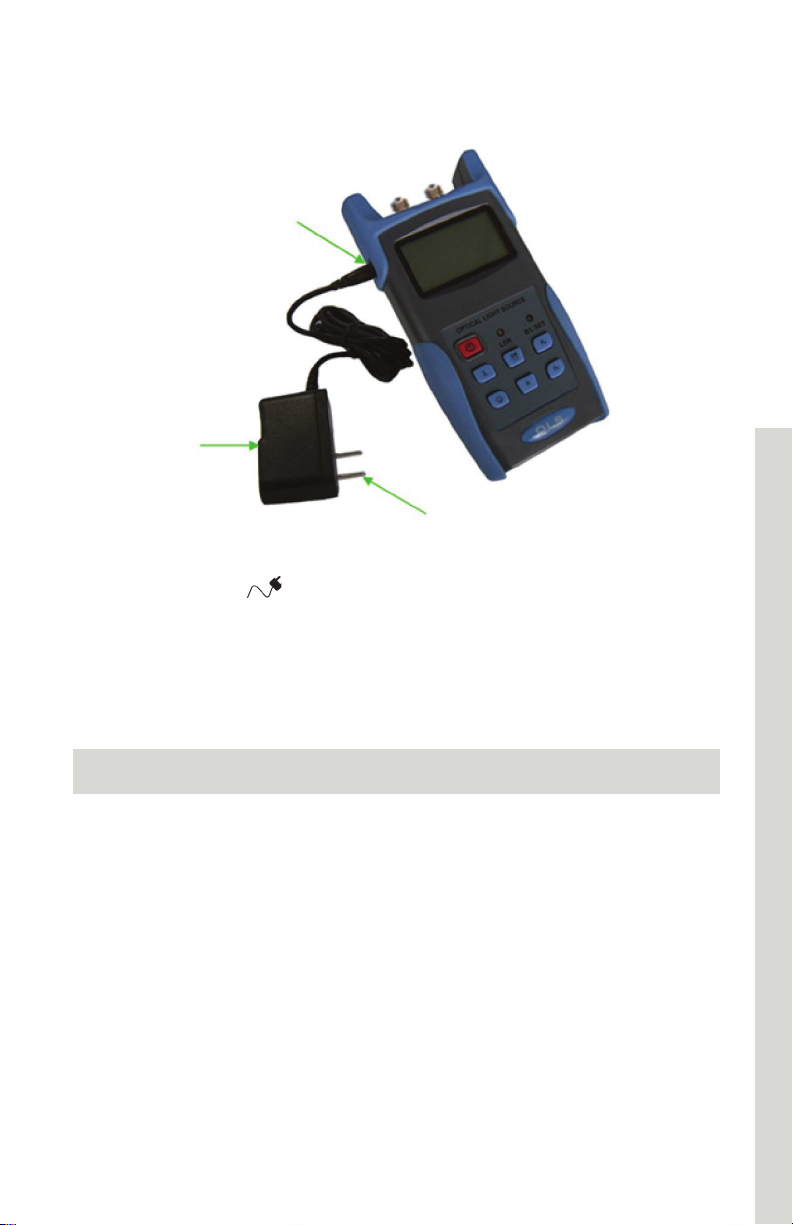
AC Adapter
AC power can be used when the batteries are empty. The AC
adapter indicator,
power is in use (Fig X, 2). The power meter will default to AC power
supply if charged batteries are present in the unit when it is plugged
in.
, will display on the left of the screen when AC
When using the AC adapter, connect the power plug (pictured) and
insert it into the AC adapter port
Note
Only use the power supply unit supplied with the tester. Using
another type of power supply may damage the instrument.
26
Page 28
Handheld Optical Power Meter
Connecting Cables
Connecting USB Cable
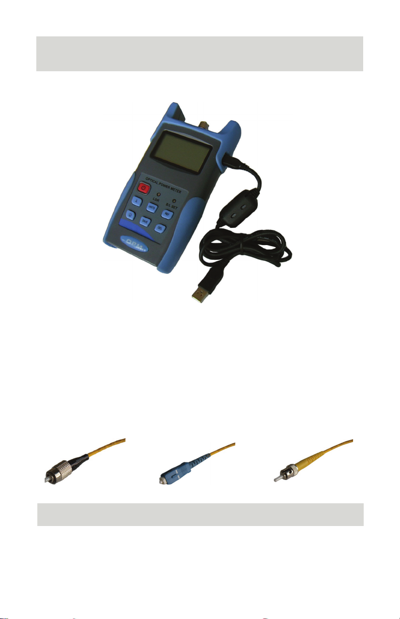
Use the USB cable supplied with the power meter to connect the
power meter to a USB port on a PC.
Connecting Patch Cable
To connect a patch cable, remove the dust proof cap.
This power meter accepts SC and ST connectors (SC & Φ2.5mm).
For LC testing, utilize SC to LC reference patch cords and included
LC-type adapters.
FC Patch Cord
Note: When changing the optical connector, be careful of the
connector and the end-face.
SC Patch Cord ST Patch Cord
Note
27
Page 29
Handheld Optical Power Meter
Turning the Power Meter On or Off
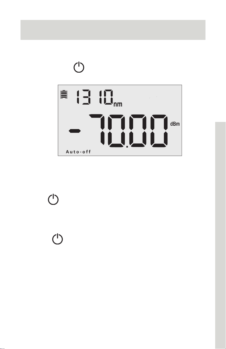
Turning the Power Meter On
1. Insert the battery or connect the power supply unit.
2. Press and hold
on the tester.
See page 24 for screen details
Auto Shutdown Function
Press the key to enable or disable the auto shutdown function.
When selected, “Auto-Off” will appear at the bottom of the screen.
The light source will shut down automatically after 10 minutes idle.
Turning the Power Meter Off
Hold down to turn off the power meter.
28
Page 30
Handheld Optical Power Meter
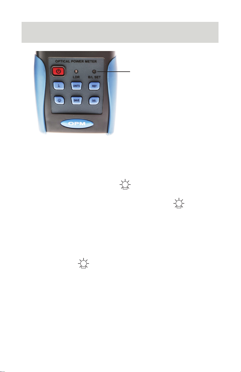
Backlight Control
B/L SET
1. Green when LDR activates
2. Red when key control
mode activates
LDR: Intelligent Backlight Control Mode
In LDR, the power meter will automatically adjust the backlight to
ambient light within 15 seconds.
Key Control Mode
In key control mode, pressing the key turns the backlight on or
off.
1. With power meter turned on, press and hold the key.
2. The BL/SET light will turn red. (Fig X)
3. After 10 seconds, the indicator light will turn off. Key control
mode is active.
Changing Backlight Mode
Press and hold the key to switch from one backlight mode to
the other. Green B/L Set light indicates the LDR is active.
29
Page 31
Handheld Optical Power Meter
Wavelength
Calibrating Wavelength
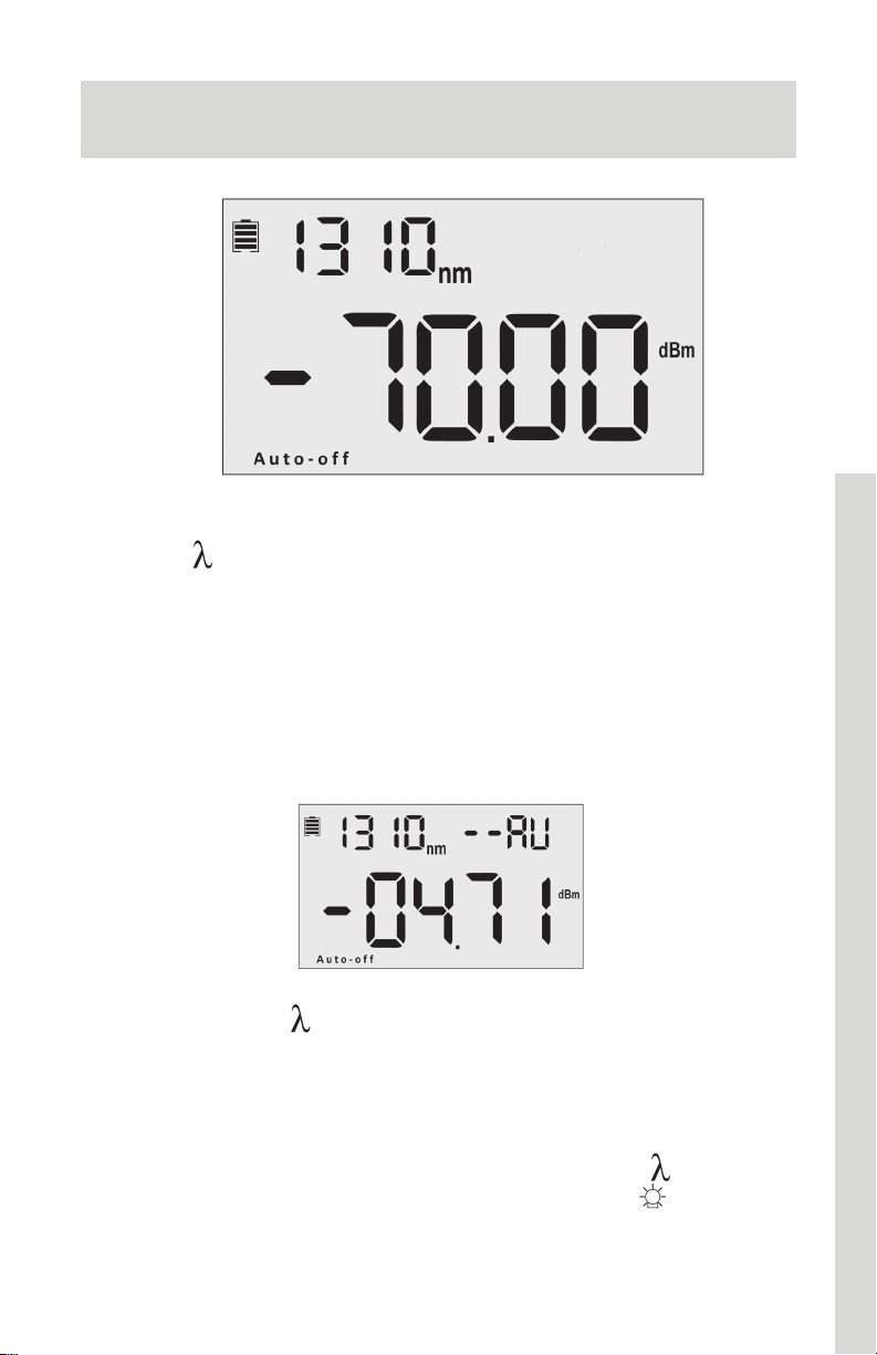
1. Press to select wavelength (displayed on top left of the
screen). 1310nm is the default value.
2. For testing, the wavelength value must be the same as the value
on the matched light source.
3. Multimode testing: 850nm or 1300nm
4. Single mode testing: 1310nm or 1550nm
Automatic Wavelength Detection
1. Press and hold until --AU appears in the upper right corner
(pictured above). B/L set light will also illuminate. This indicates
that Wavelength Auto Identification mode is active. Wavelength
will be detected based on the settings of the matched light
source.
2. To exit Wavelength Auto ID mode, press and hold
disappears. B/L set light will stay illuminated until
3. For information on configuring these settings with light source,
see next page.
30
until --AU
is pressed.
Page 32

Handheld Optical Power Meter
Automatic Wavelength Identification Configuration
1. Connect the power meter to its match light source, using the
correct patch cable. On the light source, press
laser.
to activate
2. On the light source, press and hold
the upper right corner of the screen. This indicates that Wave ID
mode is active.
3. On the power meter, press and hold
the upper right corner of the screen. Wave ID mode is now
active.
4. Press
After 3-5 seconds, the power meter will update to match the
wavelength
5. To exit Wave ID, press and hold
light source, press and hold
(0Hz).
1. To avoid the risk of serious eye damage, do not look into the
laser on the light source at any time.
2. Wave ID Mode and Auto Frequency Detection cannot
operate at the same time.
to change wavelength on light source as desired.
to return to continuous wave
Note
until --AU appears on
until --AU appears on
on the power meter. On the
31
Page 33
Handheld Optical Power Meter
Automatic Frequency Detection
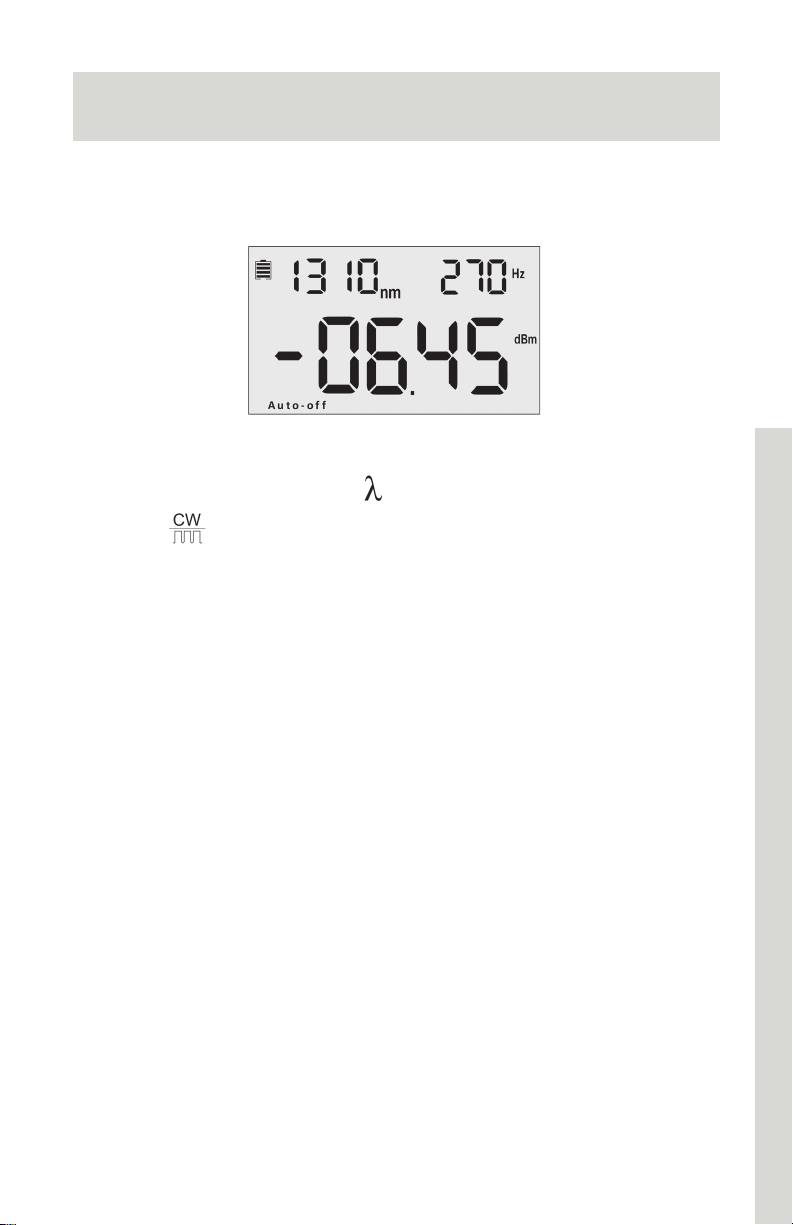
Automatic Frequency Detection will operate by default when
Automatic Wavelength Identification mode is not in use.
Light Source Screen
1. Connect the power meter to its matched light source.
2. On the light source, press
3. Press
(270Hz, 330Hz, 1KHz, or 2KHz). This will display on the upper
right of the screen.
4. Selecting a specific wavelength can improve test result
accuracy.
5. The optical power meter will detect the frequency automatically.
on the light source to select modulation frequency
to activate laser.
32
Page 34
Handheld Optical Power Meter
Choosing Units
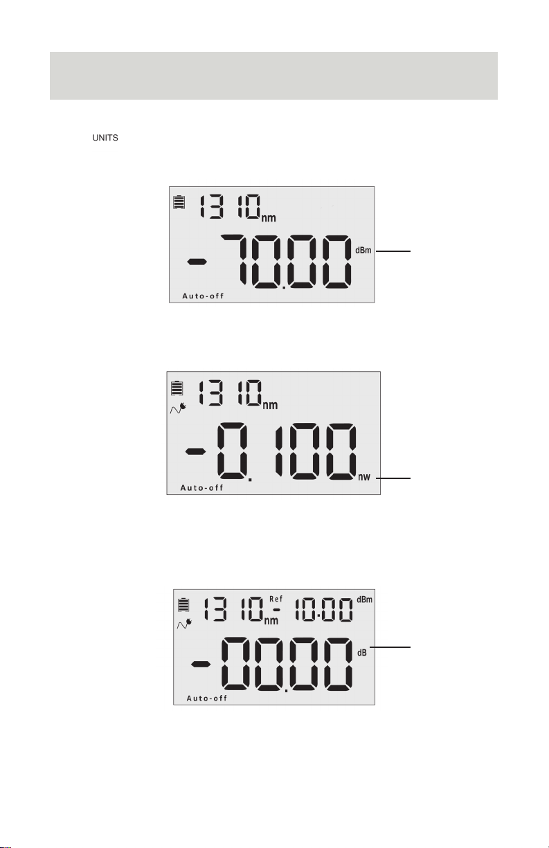
Press to select absolute power measurement (dBM), relative measurement used for loss (dB), and milliwatts/microwatts/
nanowatts (xW).
dBm
Absolute power is measured in dBm, or decibel-milliwatts. This is
a ratio of decibels of power as referenced to 1 milliwatt. 0 dBm = 1
milliwatt, -10 dBm = 0.1 milliwatt, and 10 dBm = 10 milliwatts.
xW
The power meter can also express power in milliwatts, microwatts,
or nanowatts. It is more common to utilize dBm as dBm provide a
more efficient way of expressing wide ranges of power values.
0.001mW =1 uW = 1000nW
dB
Optical loss is measured in decibels (dB) and will appear as a
negative value (i.e. -2.1 dB). dB expresses the ratio of measured
power to reference power.
dB =10log(measured power/reference)
33
Page 35
Handheld Optical Power Meter
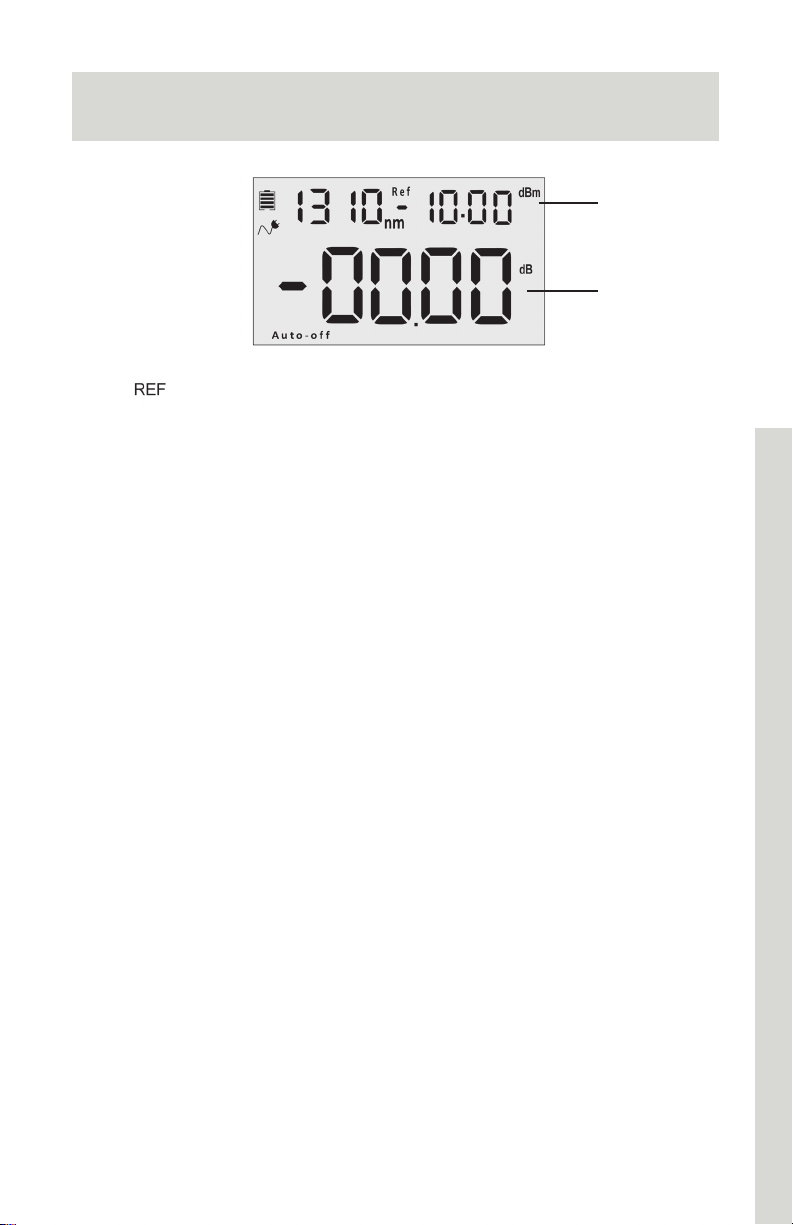
Setting Reference Value
Reference
Value
Relative
Value
(Loss)
Press
value, displayed at the top right of the screen along with “Ref” at the
center of the screen.
The set reference value will be compared to current value and used
to calculate dB (relative value).
to store the current power value (dBm) as the reference
34
Page 36
Handheld Optical Power Meter
Managing Data Records
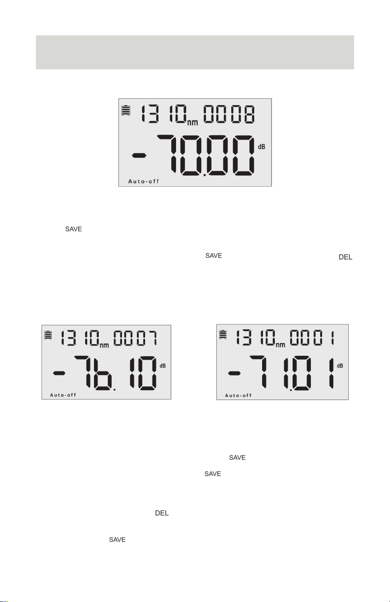
This power meter can store up to 1000 data records.
Saving Records
Press to record testing data. The record number will display at
the top right of the screen.
To confirm and save the data, press
Keeping a written log of the record number is also recommended for
reference.
twice. To cancel, press
Newest Oldest
Viewing and Deleting Records
To view previous records, press and hold . The most recently
saved data will be displayed. Press
previous data records (newest to oldest)
To delete a record, press
Press and hold to exit.
35
again to scroll through the
Page 37

Handheld Optical Power Meter
Downloading and Installing Software
To download and install the SSF-TKITP-400 Software, please visit
cleerlinefiber.com/downloads/
Select SSF-TKITP-400 Testing Kit Software.
Please follow the instructions on the web page for installation.
36
Page 38
Handheld Optical Power Meter
Software Set-Up
Note
Prior to attempting to connect the power meter to your
computer, visit cleerlinefiber.com/downloads to download and
install the TKITP-400 software.
Compatibility: Windows 7, 10
Connecting the Power Meter
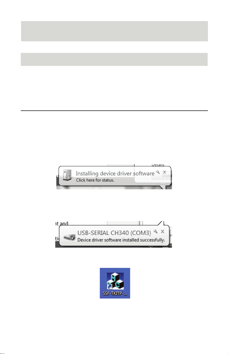
1. With the Power Meter turned off, connect the USB cable to
Power Meter and computer USB port.
2. Turn on Power Meter
3. “Installing device driver software” dialog will appear
automatically.
4. USB-SERIAL CH340 (Com3) will install after approximately 2-3
minutes.
5. Once Power Meter has installed, select SSF-TKITP-400 desktop
icon to open.
37
Page 39
Handheld Optical Power Meter
Com
Selection
Language
Settings
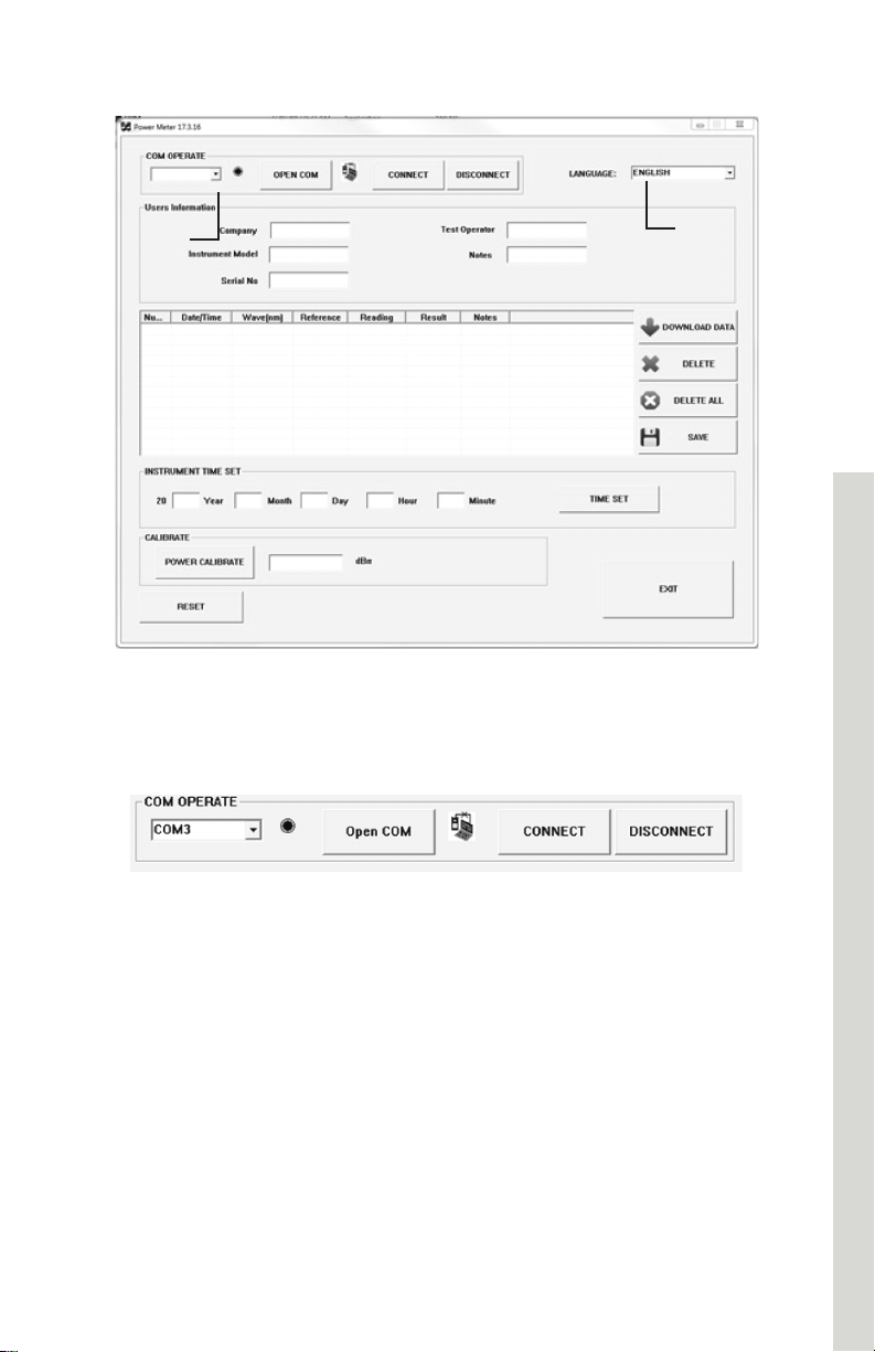
Software Interface
6. Software panel will open.
If text appears as non-English characters, select the dropdown
menu on the upper far right and change the language to English.
7. Under the Com Operate menu, select the Com (generally
Com3). If an option does not appear, it indicates that the Power
Meter driver has not installed correctly.
Troubleshooting
• To troubleshoot, first turn off the Power Meter and disconnect from
the computer. Reattached USB cable and turn Power Meter back
on. “Add new hardware” dialog should appear
• If this is unsuccessful, restart computer and attempt the step
above
• Should this not allow connection, attempt reinstalling the software
8. Once Com has been selected, click “Open Com” button
followed by “Connect.” “Connect Success” message indicates
successful connection.
38
Page 40
Handheld Optical Power Meter
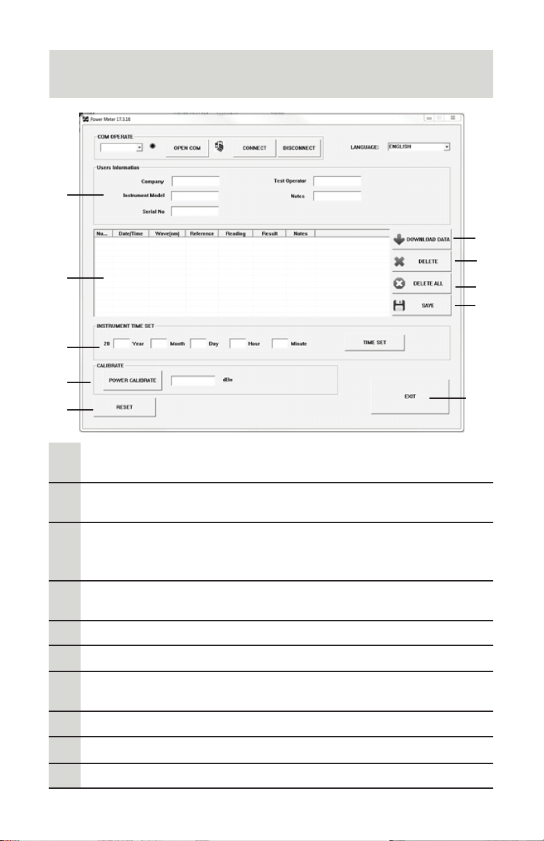
Using Test Kit Software
1
6
7
2
3
4
5
8
9
10
Users Information fields: These fields allow report data to be
1
customized with operator information
Data field: Data downloaded from the Power Meter will
2
appear in this field
Instrument Time Set: To set the time shown with the data
records, fill out Year, Month, Day, Hour, and Minute. Click
3
“Time Set” to save.
Power Calibrate: Set the dBm on the device from within the
4
software. Enter the dBm and choose ‘Power Calibrate’.
Reset: Resets device
5
Download Data: Download test records from the Power Meter
6
Delete: To delete a record, click into the row with the desired
7
data to select and click the delete button
Delete All: Deletes all records
8
Save: Automatically exports data to a .CSV file
9
Exit: Exits interface
10
39
Page 41

Handheld Optical Power Meter
Maintenance and Troubleshooting
1. Always keep the connector ports of the power meter clean.
2. Use the regulated optical connector for testing.
3. Use the adapters supplied with the kit only
4. Connect/disconnect fiber connectors/adapters carefully to avoid
scratches on the port of the power meter.
5. Clean the optical port of power meter regularly. Clean using
cotton swabs supplied and isopropyl alcohol as directed.
6. When using AC adapter, ensure power supply is within the
required voltage range.
7. Remove the batteries when light source not in use for extended
periods of time.
Troubleshooting
Issue Possible Reason Solution
Faint screen display Low battery power
(A) Optical
Inaccurate
Measurements
Connector is not
clean
(B) Incorrect fiber
connection
Charge or replace
the battery.
(A) Clean optical
connectors
(B) Reconnect the
fiber
Warning
1. Ensure the connector is clean before testing.
2. Only use the supplied adapter.
3. Do not look into the laser when unit is on.
4. Charge the batteries before use. Do not charge in unit.
5. Cover optical port with dust-proof cap when not in operation.
6. Clean the optical port of the power meter regularly.
40
Page 42

Handheld Optical Power Meter
Warranty
Caution: Do not attempt to repair as doing so will void warranty.
This Optical Power Meter is covered by an 18 month warranty
1. We warrant that this power meter will be free from defects in
material and workmanship for 18 months. Should the device
fail at any time during this warranty period, we will, at our sole
discretion, replace and repair or refund the purchase price of
the product. The worth of the repair or replacement will not be
higher than purchasing price of this unit.
2. If device issues cannot be solved by the troubleshooting
methods, please contact us or the local distributor directly.
3. We will repair or replace the unit free of charge in case of defects
in production, workmanship or material. This warranty only
applies to the unit under normal operation without any damage
or misuse/abuse.
4. The shipping costs incurred by repair or replacement for the unit
under warranty will be shared by both parties.
41
Page 43

Handheld Optical Power Meter
42
 Loading...