

Cleerline SSF-TKITE-100, SSF-TKITE-1MM, SSF-TKITE-1SM Quick Start Manual
Cleerline SSF™ TKITE-1xx Test Kit
SSF-TKITE-100/1MM/1SM Quick Start Guide
WARNING: LIGHT SOURCE LASER DOES NOT OPERATE AT VISIBLE WAVELENGTH. LIGHT IS NOT VISIBLE WHEN LASER
IS ACTIVE. TO AVOID THE RISK OF EYE DAMAGE, DO NOT LOOK AT LASER WHEN LIGHT SOURCE IS OPERATIONAL.
Your power meter and light source units will be used to measure loss in dB of the power transmitted into the cable by the light source
versus power measured on the receiver end by the power meter. Loss testing is done at wavelengths for the fiber in use, typically
850nm for multimode and optionally at 1300nm, while single mode is tested at 1310nm and optionally 1550nm. The measured loss
can be compared to the estimated loss for the link or “loss budget.”
This testing kit combined with the included reference cables allows for single-ended loss testing of fiber optic cables. Double ending
requires additional reference cables (part number SSF-REFCBL-MM = multimode or SSF-REFCBL-SM = single mode).
For set-up, allowable loss, link budget calculations, etc., the Fiber Optic Association (FOA) is a great resource for testing guidelines.
FOA power testing instructions are included with your kit and should be reviewed prior to using this equipment. Information on the
two noted tests above can be found via the FOA at www.thefoa.org, including fiber optic testing methods and standards.
**AAA (1.5 V) BATTERIES REQUIRED. BATTERIES NOT INCLUDED. INSERT 3 PER UNIT TO OPERATE.**
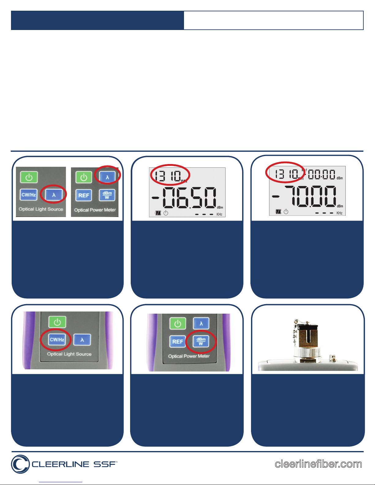
1. Select correct light source for fiber type being
tested (SM = single mode or MM = multimode;
labeled above screen on left). Turn on both light
source (OLS) and power meter (OPM).
Set both the OPM & OLS units to the desired
wavelength by pressing the wavelength button
on each unit.
850nm: Typical multimode testing
1310nm: Typical single mode testing
2. On the OLS press CW button until 1.0 KHz*
displays in lower right of the screen (see step
1A image).
*Typical testing configuration for most cables
1A. Wavelength on the OLS is displayed in the
upper left corner of the screen. Set to desired
value (press wavelength key.)
KHz (lower right) will have a numeric reading or
dashed lines when the laser is on. Dashed lines
(---) indicate that the laser is in continuous
wavelength mode.
3. On the OPM, press the “dBM/W” button until
dBM is the unit listed to the right of the main
screen read-out (see step 1B image).
1B. Set OPM to same to same wavelength as
the OLS unit. Press the wavelength button
until desired value appears.
Note: Typically 850nm for multimode testing
and 1310nm for single mode.
*Use appropriate cables. Aqua = multimode.
Yellow = single mode.
4. Plug REFERENCE cable into OLS. Note: Do
not look into laser while unit is on.
SC testing: plug appropriate multimode or
single mode cable into OLS.
LC testing: Attach appropriate SC to LC
adapter, then plug MM or SM reference cable
into adapter.
Adapter: Beige = multimode
Blue = single mode
cleerlinefiber.com
Cleerline SSF™ TKITE-100 Test Kit
SSF-TKITE-100/1MM/1SM Quick Start Guide
theFOA.org
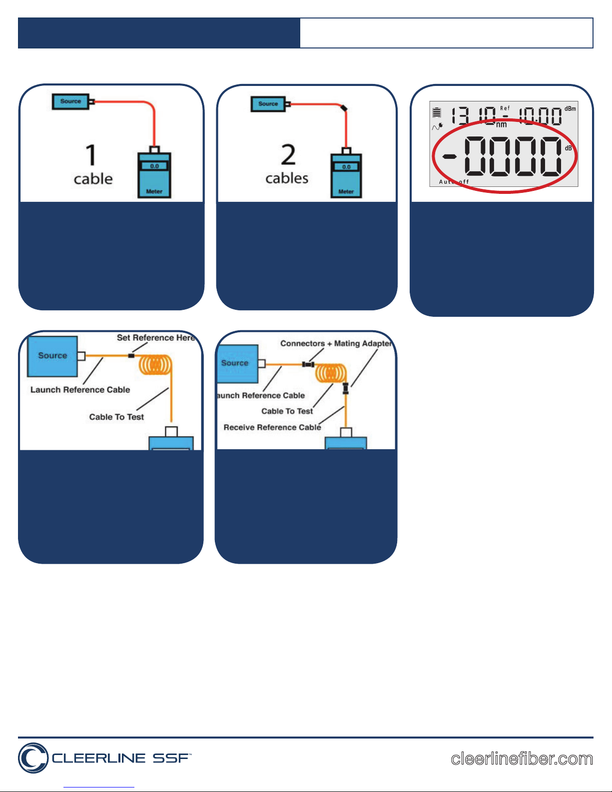
5. For single-ended testing, plug in appropriate
SC cable or LC cable with SC to LC adapters
(single mode or multimode according to the
cable being tested) between OLS and OPM.
Aqua = multimode. Yellow= single mode
theFOA.org
7A. Single-ended Testing:
Unplug connector from power meter side ONLY.
Place feedthrough SC or LC adapter, depending
on cable being tested, on connector.
Connect cable to be tested. The dB value that
appears center of screen (see step 7) is the loss
value.
Meter
theFOA.org
6. For double-ended testing, plug in two
appropriate SC cables or two LC cables with
adapters, one into OLS and one into OPM, with
SC connectors or LC to SC adapters into OPM
and OLS ports.
Link SC or LC ends together with feedthrough
adapter.
theFOA.org
7B. Double-ended Testing:
Unplug connector from SC or LC feedthrough
adapter. Place additional SC or LC feedthrough
adapter on connector.
Connect cable to be tested. The dB value that
appears center of screen (see step 7) is the
loss value.
1
Meter
7.Reference OPM.
Once cable(s) are connected between OLS
and OPM units, press and hold “REF” button
for two seconds. OPM should now read 0dB.
1
Double-ended testing is optional
2
and requires additional reference
cables. Part Number:
SSF-REFCBL-MM = Multimode
SSF-REFCBL-SM = Single Mode
2
Performing Step 7 removes the
power loss of the “reference”
cables so that the dB loss reading
of the installed cables will not
include the loss of the reference
cable(s) utilized.
Refer to the included FOA instructions “Guide to Fiber Optics & Premises Cabling” to perform A>B and B<A testing to properly
diagnose high loss connector terminations.
For accurate testing, frequent cleaning of all connector faces being placed under test, maintaining minimal bends and movement of
reference cables, and resetting of power meter reference throughout the course of testing are recommended.
cleerlinefiber.com
 Loading...