

Page 1

For additional product information visit our Web site at http://www.apextoolgroup.com
mPro400GC-DGD-intelligent-spindle
BTSE series
System Handbook
P2077SB/EN
2011-09
Page 2
2 P2077SB/EN 2011-09 77a_Deckblatt.fm, 06.09.2011
Notes on System Handbook
This System Handbook is the original system handbook – and
• provides important information on safe, correct and efficient operation of the system.
• describes the function and operation of the components.
• serves as a lexicon for technical data.
• It points out options.
Secondary information
Symbols in text
Abbreviations
Copyright protection
Apex Tool Group reserves the right to modify, supplement or improve this document or the product without prior notice. This document
may not be reproduced in whole or in part in any way, shape or form, or copied to another natural or machine-readable language or to a
data carrier, whether electronic, mechanical, optical or otherwise, without the express permission of Apex Tool Group.
DGD is a trademark of Apex Tool Group Division.
P1908E Tightening torques – Assembling the DGD-intelligent-spindle components
P2074BA Operating instructions for telemetry system
P2075EL Data sheet: Transducer
P1913E Spare parts sheet: Gearing
P2080EL Spare parts sheet: Transducer
P1914E Spare parts sheet: Motor
P2085EL Tightening module spare parts sheet TSE/TUSE
P2076EL Spare parts sheet: Offset attachment
P2086MA DGD intelligent spindle assembly instructions
P2078MA Tightening module assembly instructions TSE/TUSE
P1919E Supply module assembly instructions CPS3
PL12DE-1001 Programming ManualmPro400GC
PL12DE-1004 Quick Start mPro400GC
P2079WA DGD intelligent spindle service manual
➔ Identifies instructions to be followed.
• Identifies lists.
italics Indicates menu items such as Diagnostics in software descriptions
<…> Identifies elements that have to be selected or deselected, such as buttons or control boxes, i.e. <F5>
Courier Indicates the name of paths and files, e. g. setup.exe
\ A backslash between two names indicates the selection of an item from the menu, e. g. file \ print
DGD-IS DGD intelligent spindles
PDB-CPS… Power distribution box
mPro400GC-M Nutsetter control unit
TSE/TUSE Tightening module
CP3-…-JH Transformer
CPS3 Supply module
Page 3

P2077SB-EN_2011-09_m-Pro-400S-DGD-IS_BTSEIVZ.fm, 06.09.2011 P2077SB/EN 2011-09 3
Contents
1 Safety 7
1.1 Warnings and notes ....................................................................... 7
1.2 Basic requirements for safe working practices..................................... 7
1.3 Operator training................................................................................... 8
1.4 Personal protective equipment............................................................. 8
1.5 Designated use..................................................................................... 8
1.6 Ambient conditions ............................................................................... 9
1.7 EMC (Electromagnetic compatibility).................................................... 9
1.8 Noise................................................................................................... 10
2 Transport / Storage 10
3 System description 11
3.1 Components ....................................................................................... 11
4 First Operation 13
5 DGD intelligent spindles 15
5.1 General technical data........................................................................ 15
5.2 Catalogue data ................................................................................... 16
5.3 Component overview.......................................................................... 20
6 Tightening module TSE/TUSE 23
6.1 Description.......................................................................................... 24
6.2 General technical data........................................................................ 24
6.3 "Ready" LED....................................................................................... 25
6.4 Service panel...................................................................................... 25
6.5 Internal assemblies............................................................................. 27
7 Attachment 29
7.1 Centric Attachment............................................................................. 29
7.2 Offset attachment ............................................................................... 29
7.3 Angle head attachment....................................................................... 30
7.4 Spring collet – Optional....................................................................... 31
8 Transducer 33
8.1 Electrical Data..................................................................................... 34
8.2 Pin configuration of transducer........................................................... 34
Page 4

4 P2077SB/EN 2011-09 P2077SB-EN_2011-09_m-Pro-400S-DGD-IS_BTSEIVZ.fm, 06.09.2011
9 Gearing 35
10 Motor 35
10.1 Technical data .................................................................................... 35
10.2 Electrical Data..................................................................................... 36
10.3 Thermal data....................................................................................... 36
10.4 Pin configuration motor connector ..................................................... 37
11 Power distribution box PDB-CPS… 39
11.1 Brief function description .................................................................... 39
11.2 General technical data........................................................................ 40
11.3 Electrical Data..................................................................................... 40
11.4 Installation........................................................................................... 41
11.5 Supply module CPS3.......................................................................... 42
11.6 Transformer........................................................................................ 47
11.7 General technical data........................................................................ 47
12 Instructions on laying cables 49
12.1 General............................................................................................... 49
12.2 Strain relief clamp............................................................................... 50
12.3 Shielding............................................................................................. 50
12.4 Laying "High-Flex Quality" cables in cable ducts................................ 51
12.5 Wiring of robot area »SuperhighFlex Quality«.................................... 52
13 Cable 53
13.1 HighFlex Quality, suitable for cable ducts........................................... 53
13.2 Super Highflex, suitable for robots...................................................... 58
14 Function description 61
14.1 Torque measurement ......................................................................... 61
15 Troubleshooting 63
15.1 Acknowledgment of Errors.................................................................. 63
15.2 DGD-IS............................................................................................... 64
15.3 Tightening module CPS3 in power distribution box PDB-CPS… ....... 65
15.4 Tightening module TSE/TUSE............................................................ 70
15.5 Nutsetter control unit mPro400GC-M ................................................. 70
16 Maintenance / Service 77
Page 5

P2077SB-EN_2011-09_m-Pro-400S-DGD-IS_BTSEIVZ.fm, 06.09.2011 P2077SB/EN 2011-09 5
17 Disposal 77
Page 6

6 P2077SB/EN 2011-09 P2077SB-EN_2011-09_m-Pro-400S-DGD-IS_BTSEIVZ.fm, 06.09.2011
Page 7
77b_Sicherheit_bedingt-en.fm, 06.09.2011 P2077SB/EN 2011-09 7
Safety
1
1 Safety
1.1 Warnings and notes
1.2 Basic requirements for safe working practices
Only take the fastening system into service after you have read and completely understood the following
safety instructions and this document. Failure to observe the instructions below may result in electric shock,
fire and serious injuries.
WARNING!
A symbol combined with the word WARNING warns of a potentially dangerous situation for the health
of personnel, If this warning is not observed, death or serious injury may occur.
CAUTION!
A symbol combined with the word CAUTION warns of a potentially harmful situation for the health of
personnel or damage to property or the environment. If this warning is not observed, injuries, property
or environmental damage may occur.
DANGER!
A symbol combined with the word DANGER warns of an impending health risk or risk of fatal injury to
personnel. If this danger note is not adhered to, severest injury that may lead to the death of people, is
the consequence.
NOTE
This symbol indicates a general instruction.
General instructions include application tips and special useful information, but no warnings against
dangers.
DANGER!
High leakage current –
Fatal electric shock could occur!
➔ Establish a protective earth (PE) ground connection to the PDB-CPS… before taking into operation!
➔ Always disconnect the power supply before performing maintenance work on the DGD-IS and the
PDB-CPS….
➔ Always disconnect the system cable or motor cable from the PDB-CPS… or DGD-IS before making
throughput, resistance and short circuit measurements.
➔ Do not attempt to repair possible faults on the fastening system by yourself if you do not have the
required knowledge! Please consult your local service agent or the responsible Sales & Service Center
(see backside).
WARNING!
High temperature –
the motor on the DGD-IS may heat up and cause burns during removal. (max. engine temperature 80 °C).
➔ Wear gloves.
CAUTION!
Risk of flying parts.
Components of the spindle may rotate, come loose and cause injury.
➔ Avoid speed increases of over 3
m
/s² on all axes.
Page 8

8 P2077SB/EN 2011-09 77b_Sicherheit_bedingt-en.fm, 06.09.2011
Safety
1
➔ We do not claim that these safety notes are complete. Read and observe all applicable, general and
local safety and accident prevention rules.
➔ Follow a safety-conscious maintenance program which takes into account the local regulations for
maintenance and servicing in all phases of operation of the fastening electronics.
1.3 Operator training
• The fastening system may only be operated by personnel that have been trained and instructed
correspondingly and authorized by the operator.
• The tightening system must only be serviced by persons who have been instructed by qualified
representatives of DGD.
• The operator must make sure that all new operating and maintenance personnel are instructed in the
operation and maintenance of the fastening system to the same extent and with the same care and
attention.
• Personnel who are being trained may only work on the fastening system under the supervision of an
experienced operator.
1.4 Personal protective equipment
When working
• Wear the protective goggles to protect against spurting metal splinters.
Danger of injury by being wound up in and caught by machinery
• Wear close-fitting clothing.
• Do not wear jewelry.
1.5 Designated use
The owner is responsible for using the machine according to its designated use.
The fastening system may be used only under the following conditions:
• Industrial environment EMC limit class value A, DIN EN 55 0081-2.
• The DGD-IS is designed for stationary operation only and is intended exclusively for fastening and
loosening thread connections. Do not use as a hand-held tool.
• Only use the DGD-IS in conjunction with the power distribution box PDB-CPS… and the nutsetter
control unit mPro400GC-M.
• The DGD-IS must be fully assembled. Insert and lock all connecting cables.
CAUTION!
Work area
➔ Close all safety devices.
➔ Ensure that there is enough space in the work area.
➔ Keep the work area clean.
Electrical safety
➔ Only operate the tightening system indoors.
➔ Observe the safety notes on the DGD-IS.
Safe working with and around fastening tools
➔ Inspect screw bits and retaining ring for visible damage and cracks.
Replace damaged parts immediately.
➔ Always disconnect the power supply to the DGD-IS before changing screw bits.
➔ Only use screw bits for machine-controlled fastening tools.
➔ Make sure that the screw bits are retained securely.
Page 9
77b_Sicherheit_bedingt-en.fm, 06.09.2011 P2077SB/EN 2011-09 9
Safety
1
• Secure the DGD-IS to an electroconductive mounting plate.
• Only cable types approved by DGD may be used.
• Only accessory parts approved by DGD may be used.
• Unauthorized alterations, repairs and modifications are prohibited for reasons of safety and product
liability.
• Only operate the tightening system indoors.
1.6 Ambient conditions
Do not operate the fastening system in an explosive atmosphere.
1.7 EMC (Electromagnetic compatibility)
• The tool complies with the following applicable EMC standards:
- DIN EN 61 000-3-2
- DIN EN 61 000-3-3
- DIN EN 61 000-6-2
- DIN EN 61 000-6-4
• The filters required to fulfill the EMC standards are integrated in the system components.
• Shielded cables offer protection against irradiating and radiating interference.
• All cable shields are connected to the shield terminals on the nutsetter control unit and the plug casing
on the DGD-IS.
NOTE
➔ Always remove the complete DGD-IS from a unit.
➔ A repair is only permitted by DGD authorized personnel. If repair is required, send the complete
DGD-IS to Sales & Service Center (see backside).
➔ Do not open the transducer, offset attachment or angle head attachment as this will void the
warranty. A repair is only permitted by DGD authorized personnel. If repair is required, send the
complete component to Sales & Service Center.
➔ Do not open the TSE/TUSE or CPS3 as this will void the warranty.
This does not include the service panel. A repair is only permitted by DGD authorized personnel. If
repair is required, send the complete component to Sales & Service Center.
➔ Read the following documents when replacing the DGD-IS
• This System Handbook (see 16 Maintenance / Service, page 77)
• Service Manual DGD-IS
• Assembly instructions DGD-IS
• Spare part sheets
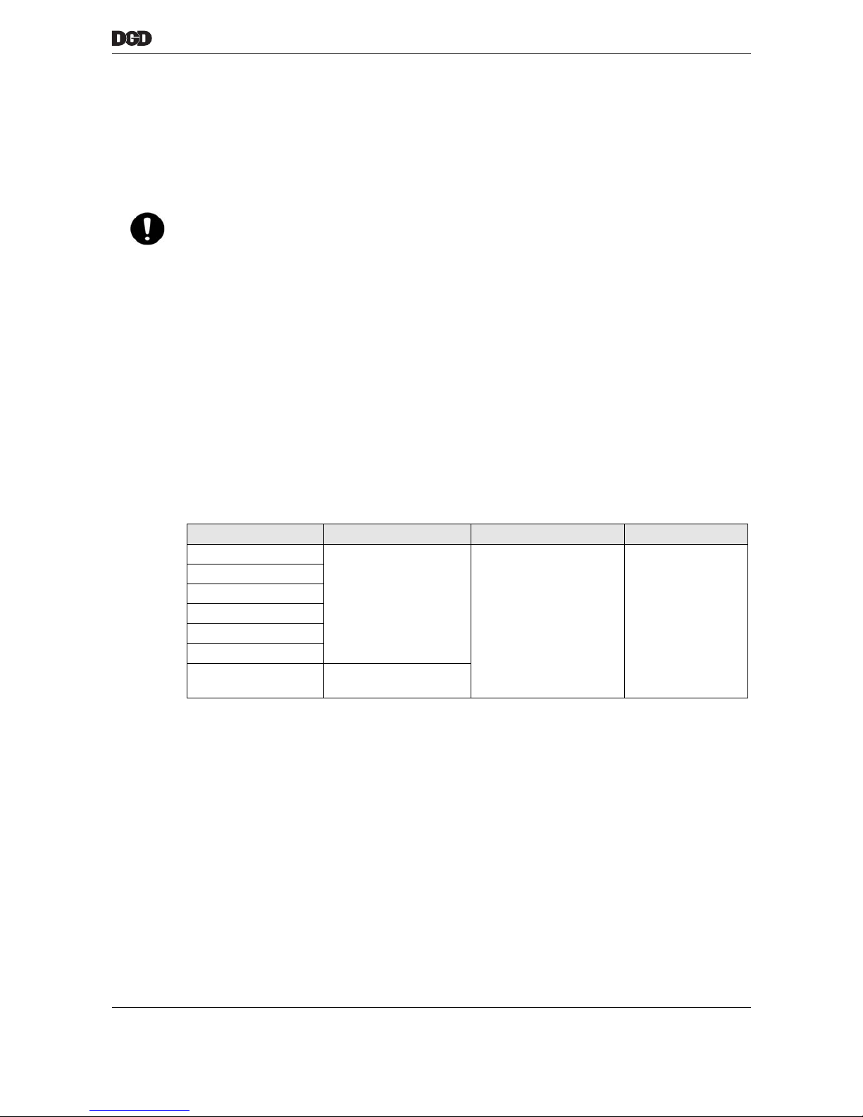
System components Ambient temperature Relative humidity Working height
DGD-IS
32 to 113 °F
(0 to 45 °C)
0 to 90 %
no condensation
up to 3000 m above
sea level
mPro400GC-M
PDB-CPS…
CP3-…-JH
TSE/TUSE
Motor
CPS3 32 to 158 °F
(0 to 70 °C)
Page 10
10 P2077SB/EN 2011-09 77b_Sicherheit_bedingt-en.fm, 06.09.2011
Transport / Storage
2
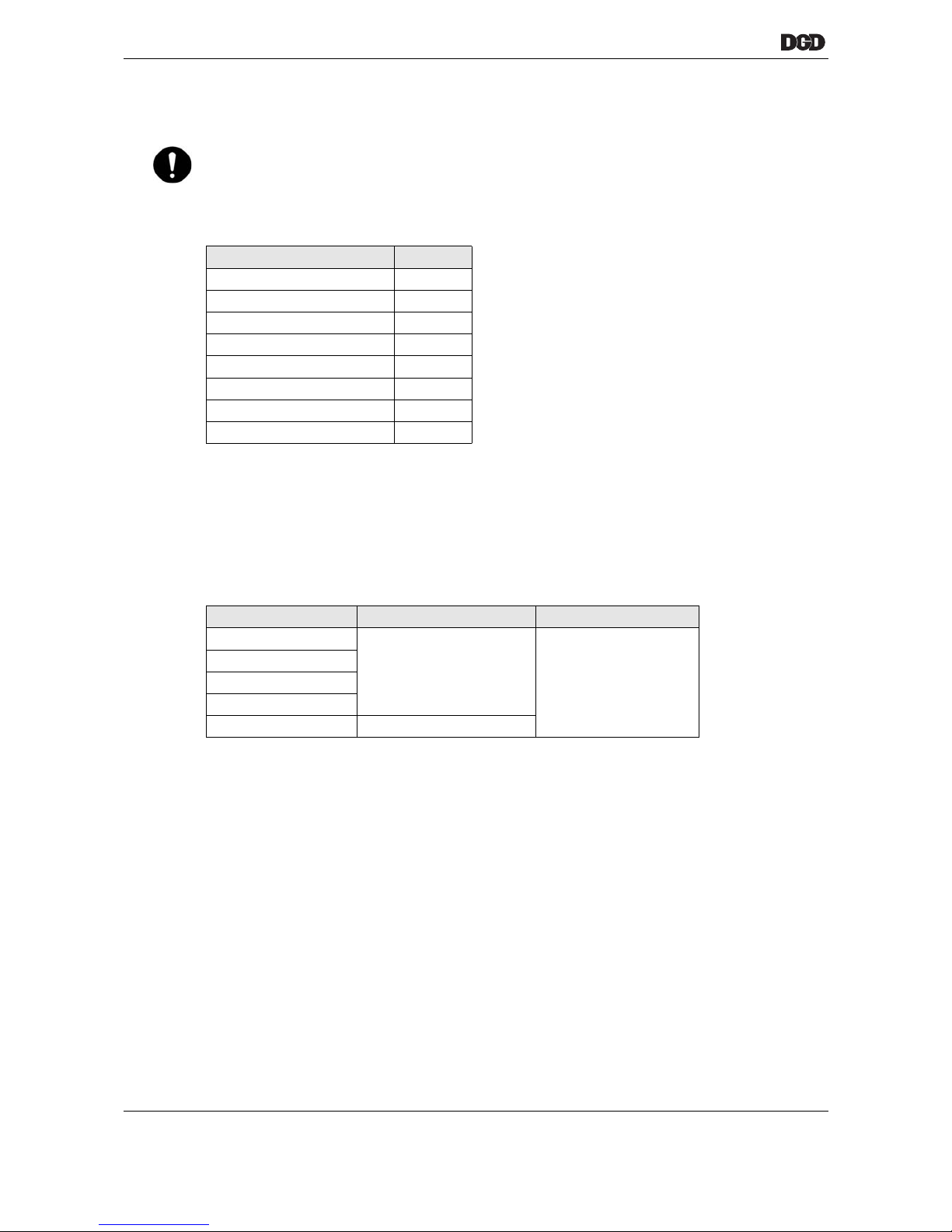
1.8 Noise
Measured sound pressure level at idling speed (no load) / clockwise rotation in accordance with ISO 3744.
2 Transport / Storage
• Transport only in the original packing.
• If the package is damaged, check the part for visible damage.
Inform the carrier or DGD if necessary.
NOTE Equipment from EMC limit class value A, DIN EN 55 0081-2.
This equipment may cause radio interference in residential areas. Should this occur, you may request
that the operator pay for and implement relevant EMC measures.
DGD-IS dB(A)
1B(U)TSE-1B012A-… 72
1B(U)TSE-1B035A-… 72
1B(U)TSE-1B060A-… 67
2B(U)TSE-2B110A-… 71
2B(U)TSE-2B200A-… 67
3B(U)TSE-3B300A-… 66
4B(U)TSE-4B500A-… 66
4B(U)TSE-4B660A-… 66
System components Storage temperature Relative humidity
DGD-IS
-20 to 70 °C
0 to 90 %
no condensation
PDB-CPS…
TSE/TUSE
Motor
CPS3 -25 to 70 °C
Page 11
77c_Systembeschreibung-en.fm, 06.09.2011 P2077SB/EN 2011-09 11
System description
3
3 System description
The system design is determined by the size and quantity of DGD-IS used and always varies depending on
the individual situation. These components can be combined with one another in various sizes.
This chapter includes a brief description of the components. Each respective chapter contains separate
technical details.
Special features of the fastening system mPro400GC-DGD-intelligent-spindle
In the mPro400GC-DGD-intelligent-spindle fastening system, the tightening modules are no longer installed
in a control cabinet, but directly on the built-in nutsetter, see system "m-Pro-400-tm" with single cable solution.
The intermediate circuit voltage was increased from 320 VDC to 380 VDC compared to the "TM" tightening
modules. This increased the maximum speed of the built-in nutsetter by 20 %.
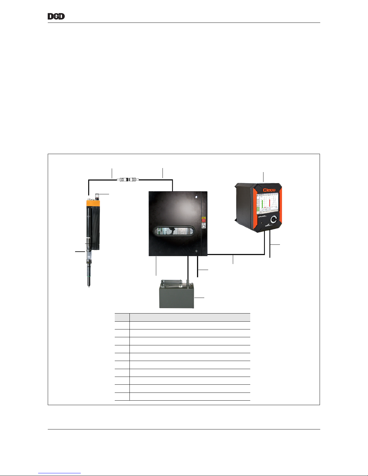
3.1 Components
77_system.png
1
Item Designation
1 Nutsetter control unit mPro400GC-M
2 ARCNET cable Order no. 960950-××× (××× = length in dm)
3 Mains cable, 3×480 VAC
4 Transformer CP3-…JH
5 Power distribution box PDB-CPS…
6 DGD-IS
7 ARCNET terminator
8 System cable, type A
9 System cable, type C
10 Power cable
6
3
5
4
7
9
8
2
10
Page 12
12 P2077SB/EN 2011-09 77c_Systembeschreibung-en.fm, 06.09.2011
System description
3
3.1.1 DGD-IS
The DGD-IS is available in sizes 1B(U)TSE…, 2B(U)TSE…, 3B(U)TSE… and 4B(U)TSE….
for a torque range of 2 to 1600 Nm.
3.1.2 Nutsetter control unit
Power and logic are supplied via the power distribution box PDB-CPS….
This is controlled by the nutsetter control unit mPro400GC-M.
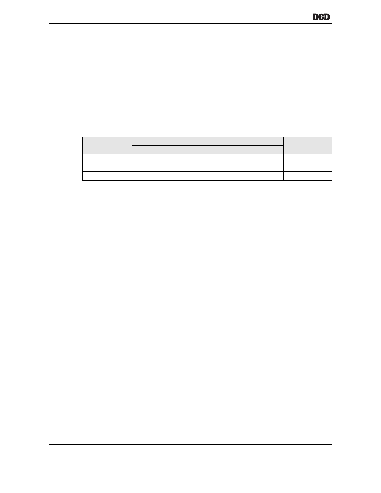
• A single system cable (PDB-CPS… to the last DGD-IS) may have up to 16 DGD-IS units connected
(depending on the size and number).
• A single mPro400GC-M can have up to 32 DGD-IS units connected.
Available channel numbers
The maximum number of DGD-IS units per PDB-CPS… depends on load.
In order to guarantee the number stated, the following settings are to be made:
• Maximum speed at 20% of maximum torque (for 1BTSE, 2BTSE, 3BTSE and 4BTSE)
• Final tightening up to 500 Nm: Maximum speed 50
rpm at maximum torque (for 1BTSE, 2BTSE, 3BTSE
and 4BTSE- 4B500A...)
• Final tightening above 500 Nm: Maximum speed 20
rpm at maximum torque (for 4BTSE-4B660A...,
4BTSE-4B660A-4VK4MS, 4BTSE-4B360A-4Z1250A and 4BTSE-4B460A-4Z1600A)
If settings above those stated are selected, the number of channels must be reduced.
If using different types of spindle on one control unit, these must be individually defined.
Please consult your Sales & Service Center (see backside).
3.1.3 Cables
From PDB-CPS… to the last DGD-IS = 50 m maximum length.
3.1.4 ARCNET (System bus)
Communication between the mPro400GC-M and the DGD-IS is achieved via the serial, high-performance
field bus ARCNET, based on RS485.
• An ARCNET cable is connected between mPro400GC-M and PDB-CPS….
• ARCNET cables are integrated in the system cable between PDB-CPS… and DGD-IS, and between
DGD-IS and DGD-IS.
• Several system wiring harnesses meet at PDB-CPS6 and PDB-CPS9. An ARCNET bus amplifier
module (ARCNET HUB 1E3A order no. 961237) is installed for this purpose. The module allows a starshaped bus topology.
Code Maximum number of DGD-IS Quantity
System cable
1B(U)TSE… 2B(U)TSE… 3B(U)TSE… 4B(U)TSE…
PDB-CPS3 16 6 6 6 1
PDB-CPS6 32 12 12 12 2
PDB-CPS9 – 18 18 18 3
Page 13

77d_Inbetriebnahme_bedingt-en.fm, 06.09.2011 P2077SB/EN 2011-09 13
First Operation
4
4 First Operation
For initial commissioning, the mPro400GC programming instructions must also be read and applied.
1 Position components of the DGD-IS so that they interlock at toothed interfaces, see Service Manual:
Turn size 1 in 15° increments.
Turn sizes 2 to 4 in 10° increments.
2 Connect all components, see (Chapter "3.1"Components starting on page 11).
3 Close all plug connectors and lock.
4 Connect the mains cable to the nutsetter control unit.
5 Preset the ARCNET address on each DGD-IS under the service panel,
see 6.4.1 ARCNET address preset, page 26.
6 Close the service panel.
7 Close the protective devices (i.e. safety grilles).
8 Switch on the machine control unit (PLC/SPS).
9 Switch on the nutsetter control unit.
If there are no faults pending after switching on the unit, the
"Ready" LED on the DGD-IS lights up green.
Otherwise, please refer to 15 Troubleshooting, page 63,
troubleshooting.
10 Enter parameters for torque / angle of rotation setting via
the mPro400GC-M….
The mPro400GC-M is programmed by DGD technical staff
during commissioning.
The first time the nutsetter control unit is switched on, the parameters for controlling fastening
sequences must be read in via the keyboard or a valid parameter file. For process programming of the
nutsetter control unit, see Programming Manual mPro400GC-M.
CAUTION!
Risk of tripping or falling over loose cables on the ground.
Lay all connected cables safely.
NOTE
The red ring around the outer diameter of plug connectors with a slide lock should not be visible.
NOTE
Always terminate the ARCNET with an ARCNET terminator at the bus end, i.e. at the last DGD-IS,
order no. 961127. This terminator is permanently installed in the nutsetter control unit mPro400GC-M (start
of bus).
DANGER!
High leakage current – Fatal electric shock could occur.
Establish a protective earth (PE) ground connection to the nutsetter control unit before taking into operation!
NOTE
Each address can be used only once in the system!
"Ready" LED
Page 14

14 P2077SB/EN 2011-09 77d_Inbetriebnahme_bedingt-en.fm, 06.09.2011
First Operation
4
Blank page
Page 15
77e_IntelligenteSpindel-en.fm, 06.09.2011 P2077SB/EN 2011-09 15
DGD intelligent spindles
5
5 DGD intelligent spindles
5.1 General technical data
• torque measurement with integrated pre-amplifier, resulting in greater signal noise spacing
• reverse voltage protected supply
• short-circuit proof outputs
• low voltage monitor
• watchdog for processor
• noise-protected input and output circuit
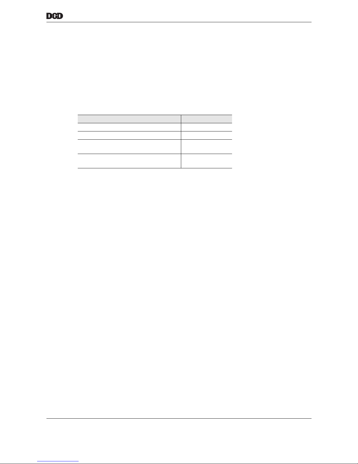
Features Data
Protection category IP54
Service life, operating 40,000 h
Load cycles
(min. at maximum torque)
1,000,000,
then recalibration
Mechanical overload capacity of the measuring shaft
100 %
Page 16
16 P2077SB/EN 2011-09 77e_IntelligenteSpindel-en.fm, 06.09.2011
DGD intelligent spindles
5
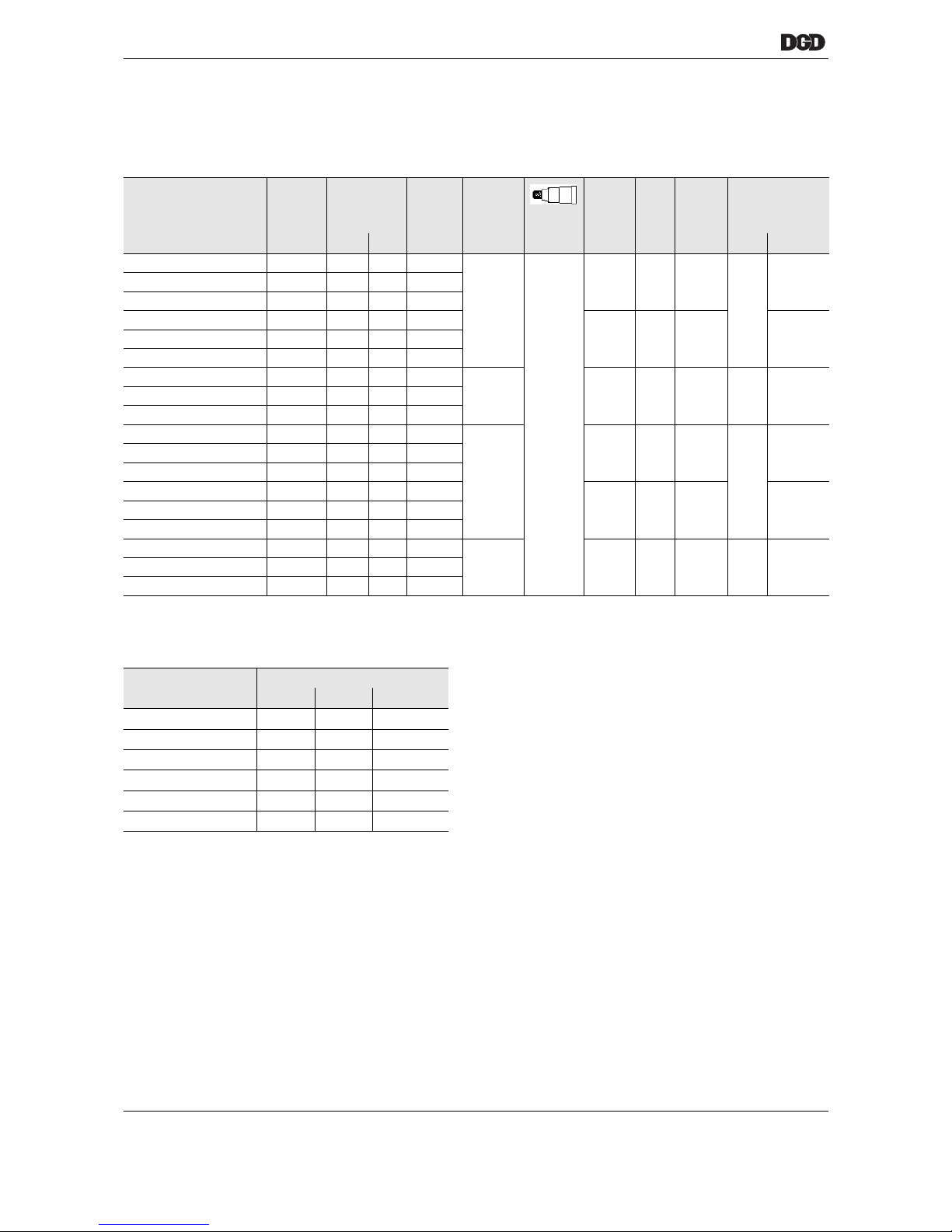
5.2 Catalogue data
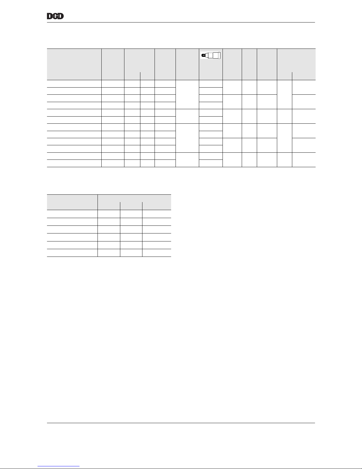
5.2.1 Size 1 – 1× transducer
Smallest scribed circle diameter in mm
Designation Order No. Torque
Nm
Speed Spring
travel
min.
axis
distance
Length
Weight Spring
chuck
max. min. RPM mm mm mm kg + flange
1BTSE-1B012A-1M3B-1ZB 947626A6
1)
1) On request
12 2 1921
50
3/8"
43 486 4.8
922325
S3084341BTSE-1B035A-1M1B-1ZB 947632A8 35 5 727
1BTSE-1B060A-1M2B-1ZB 947638A2 53 15 427
1BTSE-1B012A-1VM3B 947627A5
1)
12 2 1825
35 474 5.3 S3084371BTSE-1B035A-1VM1B 947633A7 35 5 690
1BTSE-1B060A-1VM2B 947639A1 53 15 405
1BTSE-1B012A-1WM3B 947628A4
1)
12 2 1801
25 52 542 5.7 – 9290411BTSE-1B035A-1WM1B 947634A6 35 5 681
1BTSE-1B060A-1WM2B 947640A8 53 15 400
1BUTSE-1B012A-1M3B-1ZB 947629A3
1)
12 2 1921
50
43 393 5.3
922325
S3084341BUTSE-1B035A-1M1B-1ZB 947635A5
1)
35 5 727
1BUTSE-1B060A-1M2B-1ZB 947641A7
1)
53 15 427
1BUTSE-1B012A-1VM3B 947630A0
1)
12 2 1825
35 382 5.8 S3084371BUTSE-1B035A-1VM1B 947636A4
1)
35 5 690
1BUTSE-1B060A-1VM2B 947642A6
1)
53 15 405
1BTSE-1B012A-1WM3B 947631A9
1)
12 2 1801
25 52 370 6.2 – 9290411BTSE-1B035A-1WM1B 947637A3
1)
35 5 681
1BUTSE-1B060A-1WM2B 947643A5
1)
53 15 400
Quantity Attachment
DGD-IS Centric Offset Angle head
2433552
3544060
4615074
5815889
6 99 70 105
7 116 85 120
Page 17
77e_IntelligenteSpindel-en.fm, 06.09.2011 P2077SB/EN 2011-09 17
DGD intelligent spindles
5
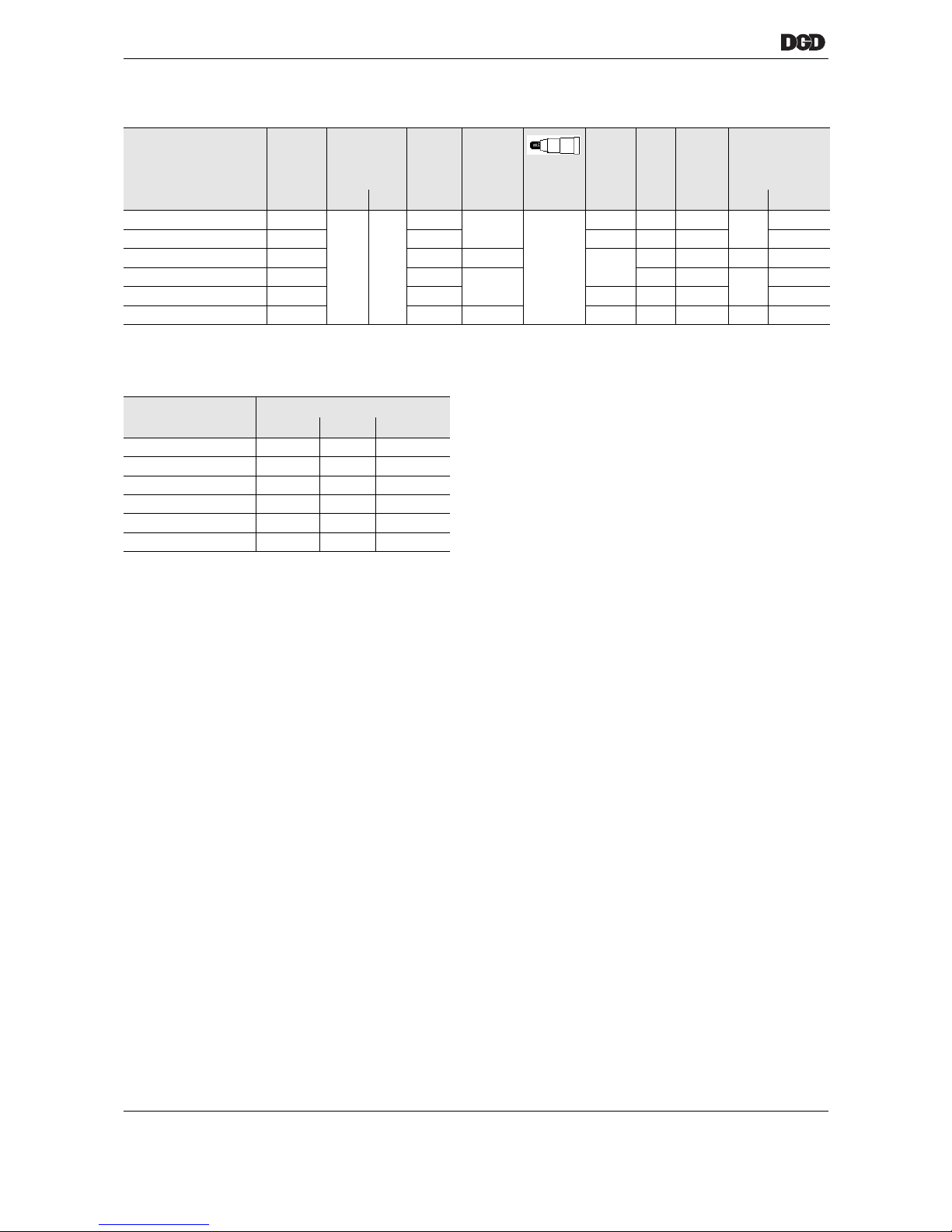
5.2.2 Size 2 – 1× transducer
Smallest scribed circle diameter in mm
Designation Order No. TorqueNmSpeed Spring
travel
min.
axis
distance
Length
Weight Spring
chuck
max. min. RPM mm mm mm kg + flange
2BTSE-2B110A-2M1B-2ZB 947644A4 110 25 890
50
1/2"
56 528 7.6
910609
S308435
2BTSE-2B200A-2M3B-2ZB 947650A6 200 40 502 3/4"
2BTSE-2B110A-2VM1B 947645A3 110 25 831 1/2"
44 551 9.2 S308438
2BTSE-2B200A-2VM3B 947651A5 200 40 468 3/4"
2BTSE-2B110A-2WM1B 947646A2 110 25 838
25
1/2"
59 581 8.7 – 929053
2BTSE-2B200A-2WM3B 947652A4 200 40 472 3/4"
2BUTSE-2B110A-2M1B-2ZB 947647A1
1)
1) On request
110 25 890
50
1/2"
56 367 8.6
910609
S308435
2BUTSE-2B200A-2M3B-2ZB 947653A3
1)
200 40 502 3/4"
2BUTSE-2B110A-2VM1B 947648A0
1)
110 25 831 1/2"
44 390 10.2 S308438
2BUTSE-2B200A-2VM3B 947648A0
1)
200 40 468 3/4"
2BUTSE-2B110A-2WM1B 947649A9
1)
110 25 838
25
1/2"
59 421 9.7 – 929053
2BUTSE-2B200A-2WM3B 947655A1
1)
200 40 472 3/4"
Quantity Attachment
DGD-IS Centric Offset Angle head
2564459
3755068
4806286
5 106 74 101
6 130 89 118
7 151 102 137
Page 18
18 P2077SB/EN 2011-09 77e_IntelligenteSpindel-en.fm, 06.09.2011
DGD intelligent spindles
5
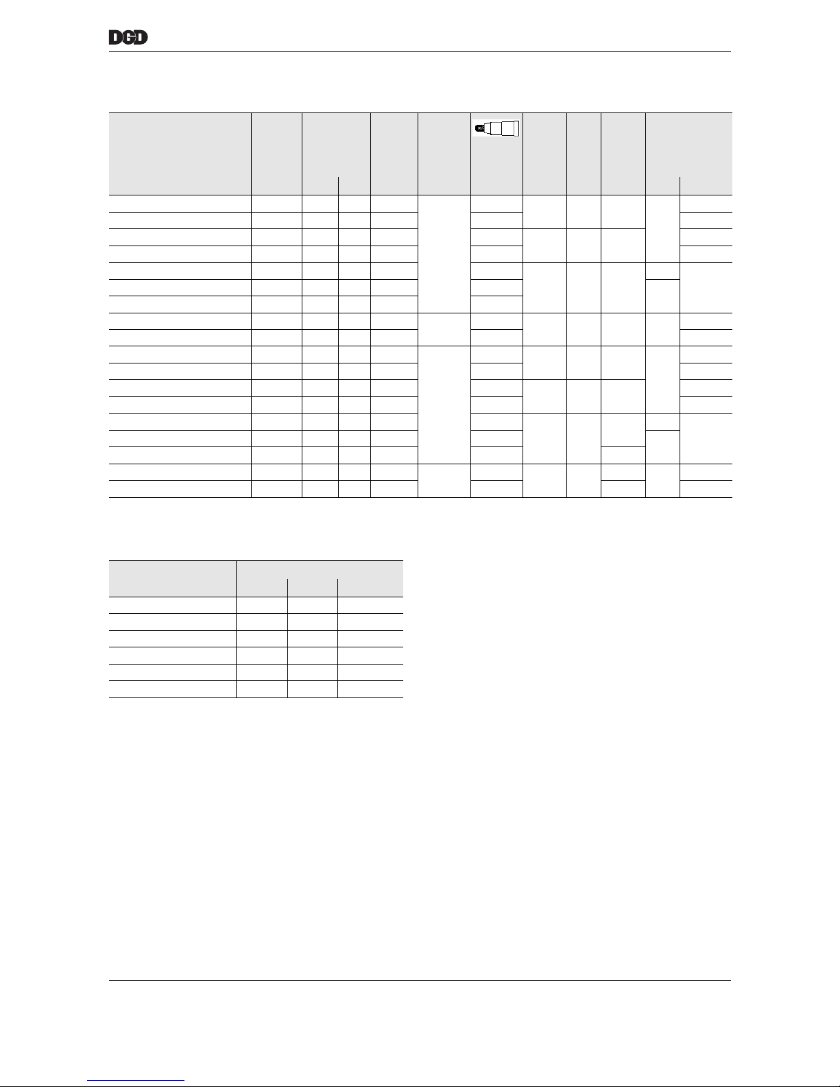
5.2.3 Size 3 – 1× transducer
Smallest scribed circle diameter in mm
Designation Order No. TorqueNmSpeed Spring
travel
min.
axis
distance
Length
Weight Spring
chuck
max. min. RPM mm mm mm kg + flange
3BTSE-3B300A-3M2B-3ZB 947656A0
300 50
453
50
3/4"
81 589 14.1
910613
S308436
3BTSE-3B300A-3VM2B 947657A9
1)
1) On request
421 59 584 15.2 S308439
3BTSE-3B300A-3WM2B 947658A8
1)
437 25
81
678 17.8 – 929065
3BUTSE-3B300A-3M2B-3ZB 947659A7
1)
453
50
417 16.1
910613
S308436
3BUTSE-3B300A-3VM2B 947660A4
1)
421 59 412 17.2 S308439
3BUTSE-3B300A-3WM2B 947661A3
1)
437 25 81 506 19.8 – 929065
Quantity Attachment
DGD-IS Centric Offset Angle head
2815981
3946994
4 116 84 116
5 139 102 139
6 164 122 164
7 189 138 189
Page 19
77e_IntelligenteSpindel-en.fm, 06.09.2011 P2077SB/EN 2011-09 19
DGD intelligent spindles
5
5.2.4 Size 4 – 1× transducer
Smallest scribed circle diameter in mm
Designation Order No. TorqueNmSpeed Spring
travel
min.
axis
dis-
tance
Length
Weight Spring
chuck
max. min. RPM mm mm mm kg + flange
4BTSE-4B500A-4M2B-4ZA 947662A2 500 100 254
50
3/4"
91 719 21
–
916643
4BTSE-4B660A-4M3B-4ZA 947668A6 660 130 174 1" 916642
4BTSE-4B360A-4M1B-4Z1250A 947676A6 1250 320 86 1"
121 771 29
S976956
4BTSE-4B500A-4M2B-4Z1600A 947678A4
1)
1) On request
1600 400 68 1 1/2" S308441
4BTSE-4B500A-4VM2B 947663A1
1)
500 100 238 3/4"
76 684 22.5
912106
S3084404BTSE-4B660A-4VM3B 947669A5
1)
660 130 163 1"
912147
4BTSE-4B660A-4VM4B 947671A1
1)
750 160 135 1"
4BTSE-4B500A-4WM2B 947664A0
1)
500 100 245
25
3/4"
112 729 27.1 –
929077
4BTSE-4B660A-4WM3B 947670A2
1)
660 130 167 1" 929089
4BUTSE-4B500A-4M2B-4ZA 947665A9
1)
500 100 254
50
3/4"
91 546 22.5
–
916643
4BUTSE-4B660A-4M3B-4ZA 947672A0
1)
660 130 174 1" 916642
4BUTSE-4B360A-4M1B-4Z1250A 947677A5
1)
1250 320 86 1"
121 599 31
S976956
4BUTSE-4B500A-4M2B-4Z1600A 947679A3
1)
1600 400 68 1 1/2" S308441
4BUTSE-4B500A-4VM2B 947666A8
1)
500 100 238 3/4"
76 512
24
912106
S3084404BUTSE-4B660A-4VM3B 947673A9
1)
660 130 163 1"
912147
4BUTSE-4B660A-4VM4B 947675A7
1)
750 160 135 1" 24.5
4BUTSE-4B500A-4WM2B 947667A7
1)
500 100 245
25
3/4"
112 556
28.6
–
929077
4BUTSE-4B660A-4WM3B 947674A8
1)
660 130 167 1" 28.7 929089
Quantity Attachment
DGD-IS Centric Offset Angle head
29176112
3 122 88 130
4 130 108 160
5 174 130 192
6 217 153 224
7 246 180 263
Page 20
20 P2077SB/EN 2011-09 77e_IntelligenteSpindel-en.fm, 06.09.2011
DGD intelligent spindles
5
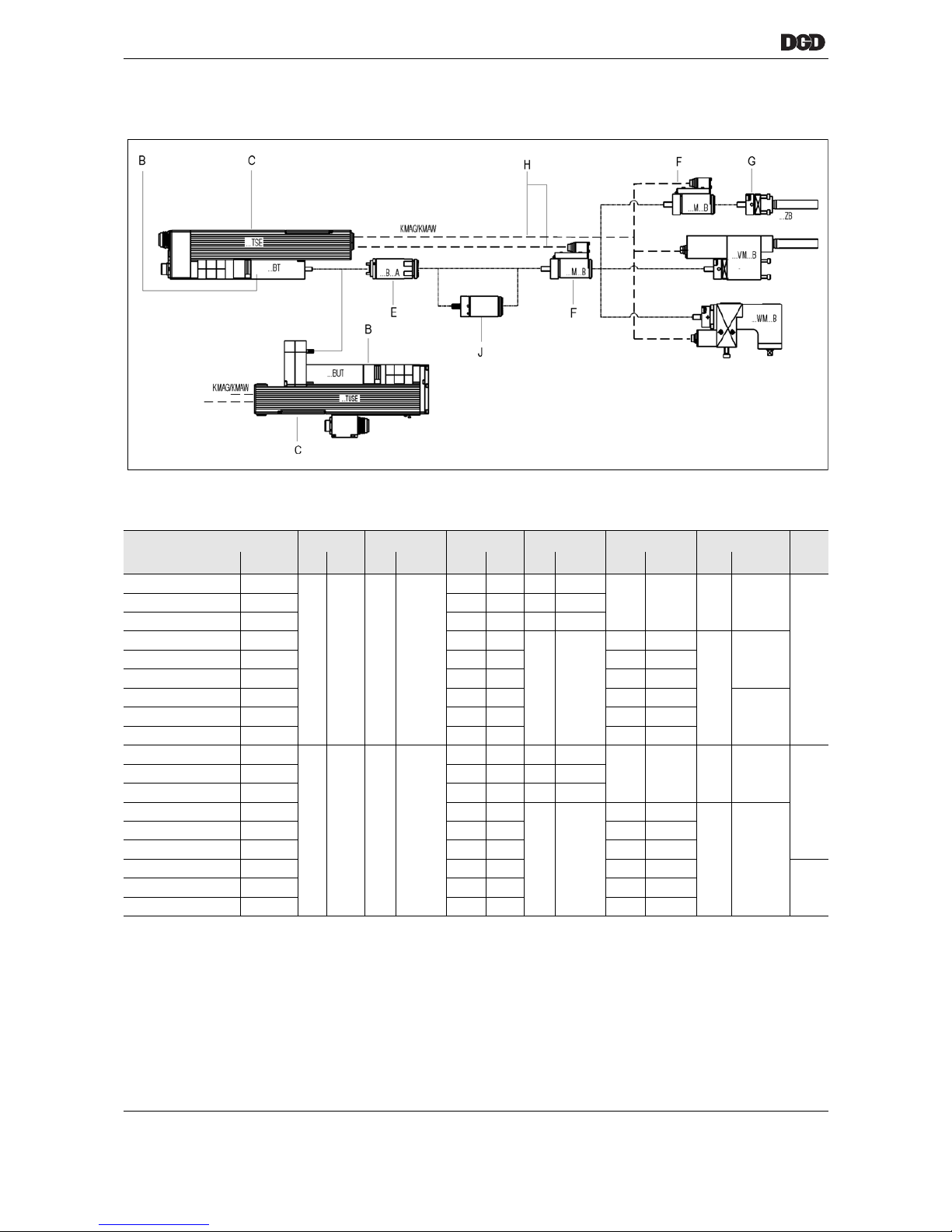
5.3 Component overview
5.3.1 Size 1 / 1× transducer
** Fit as spacer
DGD-IS B C E F G H J**
1)
1) Code
2)
2) Part no.
1) 2) 1) 2) 1) 2) 1) 2) 1) 2) 1) 2) 2)
1BTSE-1B012A-1M3B-1ZB
947626A6
1BT 935560 TSE 961446PT
1B012A 927346 1M3B 934288PT
1ZB 927222 KMAW 961089-002
–
1BTSE-1B035A-1M1B-1ZB
947632A8 1B035A 927344 1M1B 934286PT
1BTSE-1B060A-1M2B-1ZB
947638A2 1B060A 927345 1M2B 934287PT
1BTSE-1B012A-1VM3B
947627A5
3)
3) On request
1B012A 927346
––
1VM3B 935863PT
KMAG
961088-004
1BTSE-1B035A-1VM1B
947633A7 1B035A 927344 1VM1B 935865PT
1BTSE-1B060A-1VM2B
947639A1 1B060A 927345 1VM2B 935864PT
1BTSE-1B012A-1WM3B
947628A4
3)
1B012A 927346 1WM3B
3)
961088-003
1BTSE-1B035A-1WM1B
947634A6
3)
1B035A 927344 1WM1B 934367PT
1BTSE-1B060A-1WM2B
947640A8 1B060A 927345 1WM2B 934368PT
1BUTSE-1B012A-1M3B-1ZB
947629A3
3)
1BUT 936321 TUSE 961447PT
1B012A 927346 1M3B 934288PT
1ZB 927222 KMAG 961088-004
935796
1BUTSE-1B035A-1M1B-1ZB
947635A5
3)
1B035A 927344 1M1B 934286PT
1BUTSE-1B060A-1M2B-1ZB
947641A7
3)
1B060A 927345 1M2B 934287PT
1BUTSE-1B012A-1VM3B
947630A0
3)
1B012A 927346
––
1VM3B 935863PT
KMAG 961088-003
1BUTSE-1B035A-1VM1B
947636A4
3)
1B035A 927344 1VM1B 935865PT
1BUTSE-1B060A-1VM2B
947642A6
3)
1B060A 927345 1VM2B 935864PT
1BUTSE-1B012A-1WM3B
947631A9
3)
1B012A 927346 1WM3B
3)
–
1BUTSE-1B035A-1WM1B
947637A3
3)
1B035A 927344 1WM1B
3)
1BUTSE-1B060A-1WM2B
947643A5
3)
1B060A 927345 1WM2B 934368PT
Page 21
77e_IntelligenteSpindel-en.fm, 06.09.2011 P2077SB/EN 2011-09 21
DGD intelligent spindles
5
5.3.2 Size 2 / 1× transducer
5.3.3 Size 3 / 1× transducer
DGD-IS B C E F G H
1)
1) Code
2)
2) Part no.
1) 2) 1) 2) 1) 2) 1) 2) 1) 2) 1) 2)
2BTSE-2B110A-2M1B-2ZB 947644A4
2BT 935561 TSE 961446PT
2B110A 935548 2M1B 934295PT
2ZB 927227 KMAW 961089-002
2BTSE-2B200A-2M3B-2ZB 947650A6 2B200A 935549 2M3B 934294PT
2BTSE-2B110A-2VM1B 947645A3 2B110A 935548
––
2VM1B 934336PT
KMAG 961088-004
2BTSE-2B200A-2VM3B 947651A5 2B200A 935549 2VM3B 934335PT
2BTSE-2B110A-2WM1B 947646A2 2B110A 935548 2WM1B 934357PT
KMAG 961088-003
2BTSE-2B200A-2WM3B 947652A4 2B200A 935549 2WM3B 934374PT
2BUTSE-2B110A-2M1B-2ZB 947647A1
3)
3) On request
2BUT 936322 TUSE 961447PT
2B110A 935548 2M1B 934295PT
2ZB 927227 KMAG 961088-004
2BUTSE-2B200A-2M3B-2ZB 947653A3
3)
2B200A 935549 2M3B 934294PT
2BUTSE-2B110A-2VM1B 947648A0
3)
2B110A 935548
––
2VM1B 934336PT
KMAG 961088-003
2BUTSE-2B200A-2VM3B 947648A0
3)
2B200A 935549 2VM3B 934335PT
2BUTSE-2B110A-2WM1B 947649A9
3)
2B110A 935548 2WM1B 934357PT
KMAG 961088-004
2BUTSE-2B200A-2WM3B 947655A1
3)
2B200A 935549 2WM3B 934374PT
DGD-IS B C E F G H
1)
1) Code
2)
2) Part no.
1) 2) 1) 2) 1) 2) 1) 2) 1) 2) 1) 2)
3BTSE-3B300A-3M2B-3ZB 947656A0
3/4BT 935562 TSE 961446PT
3B300A 935590
3M2B 934303PT 3ZB 927233 KMAG 961088-002
3BTSE-3B300A-3VM2B 947657A9
3)
3) On request
––
3VM2B 3) KMAG 961088-004
3BTSE-3B300A-3WM2B 947658A8
3)
3WM2B 3) KMAG 961088-003
3BUTSE-3B300A-3M2B-3ZB 947659A7
3)
3/4BUT 936323 TUSE 961447PT
3M2B 934303PT 3ZB 927233
KMAG 961088-0043BUTSE-3B300A-3VM2B 947660A4
3)
––
3VM2B 3)
3BUTSE-3B300A-3WM2B 947661A3
3)
3WM2B 3)
Page 22
22 P2077SB/EN 2011-09 77e_IntelligenteSpindel-en.fm, 06.09.2011
DGD intelligent spindles
5
5.3.4 Size 4 / 1× transducer
DGD-IS B C E F G H
1)
1) Code
2)
2) Part no.
1) 2) 1) 2) 1) 2) 1) 2) 1) 2) 1) 2)
4BTSE-4B500A-4M2B-4ZA
947662A2
3/4BT 935562 TSE 961446PT
4B500A 935780 4M2B 934319PT
4ZA 927236
KMAG 961069-002
4BTSE-4B660A-4M3B-4ZA
947668A6
3)
3) On request
4B660A 935781 4M3B 936496PT
4BTSE-4B360A-4M1B-4Z1250A
947676A6 4B360A 929541 4M1B 934318PT 4Z1250A S976950
4BTSE-4B500A-4M2B1-4Z1600A
947678A4
3)
4B500A 935780 4M2B1 3) 4Z1600A S976951
4BTSE-4B500A-4VM2B
947663A1
3)
4B500A 935780
––
4VM2B 3)
KMAG 961069-004
4BTSE-4B660A-4VM3B
947669A5
3)
4B660A 935781 4VM3B 3)
4BTSE-4B660A-4VM4B
947671A1
3)
4B660A 935781 4VM4B 3)
4BTSE-4B500A-4WM2B
947664A0
3)
4B500A 935780 4WM2B 3)
KMAG 961069-003
4BTSE-4B660A-4WM3B
947670A2
3)
4B660A 935781 4WM3B 3)
4BUTSE-4B500A-4M2B-4ZA
947665A9
3)
3/4BUT 936323 TUSE 961447PT
4B500A 935780 4M2B 934319PT
4ZA 927236
KMAG 961069-005
4BUTSE-4B660A-4M3B-4ZA
947672A0
3)
4B660A 935781 4M3B 936496PT
4BUTSE-4B360A-4M1B-4Z1250A
947677A5
3)
4B360A 929541 4M1B 934318PT 4Z1250A S976950
4BUTSE-4B500A-4M2B1-4Z1600A
947679A3
3)
4B500A 935780 4M2B1 3) 4Z1600A S976951
4BUTSE-4B500A-4VM2B
947666A8 4B500A 935780
––
4VM2B 3)
4BUTSE-4B660A-4VM3B
947673A9
3)
4B660A 935781 4VM3B 3)
4BUTSE-4B660A-4VM4B
947675A7
3)
4B660A 935781 4VM4B 3)
4BUTSE-4B500A-4WM2B
947667A7
3)
4B500A 935780 4WM2B 3)
4BUTSE-4B660A-4WM3B
947674A8
3)
4B660A 935781 4WM3B 3)
Page 23
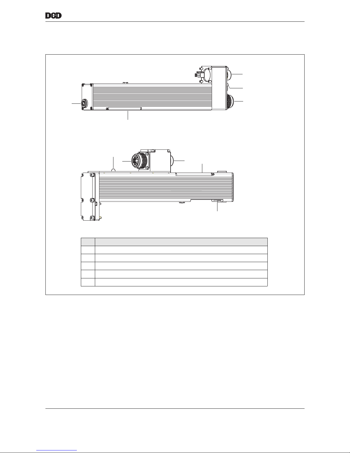
77f_Schraubmodul-en.fm, 06.09.2011 P2077SB/EN 2011-09 23
Tightening module TSE/TUSE
6
6 Tightening module TSE/TUSE
2
3
Item Designation
1 "XS1A" supply input
2 "XS1B" supply output
3 Service panel
4 "XS3" transducer plug connector
7 "Ready" LED, ready for operation (green) or fault (red)
TSE
Order no. 961446PT
TUSE
Order no. 961447PT
2
1
1
3
4
7
7
4
77_tse_tuse.eps
Page 24
24 P2077SB/EN 2011-09 77f_Schraubmodul-en.fm, 06.09.2011
Tightening module TSE/TUSE
6
6.1 Description
The tightening module TSE/TUSE controls the DGD-IS.
The servo amplifier (output section) and the measuring section (measuring board) are integrated in the
tightening module.
Both circuit boards are linked to the connections via cables and plug connectors.
6.2 General technical data
6.2.1 Power loss
Low-loss components generate minimal heat.
Extremely good heat dissipation. Overall housing serves as a cooling element.
6.2.2 Power supply 380 VDC
Intermediate power circuit (380 VDC) and logic power (24 VDC) are supplied separately by the
PDB-CPS…. In the event of an emergency stop the intermediate power circuit is switched off separately
by the PDB-CPS…. The logic section remains connected to the power.
Performance data DGD-IS different
Features Data
Weight:
TSE
TUSE
1480 g
1500 g
Protection category – is attained
when all connectors are plugged in
and the service panel is closed.
IP54
Cooling type Convection (self-cooling)
Service life, operating 40,000 h
Usability period if stored 100,000 h (approx. 11 years)
Acceleration of each axis max. 100 m/s²
Standby 9 A
Operation max. 40 W
WARNING!
High temperature –
the tightening module TSE/TUSE may heat up and cause burns during removal
(max. temperature 70 °C). Wear gloves.
Features Data
1B(U)TSE… 2B(U)TSE… 3B(U)TSE… 4B(U)TSE…
Supply voltage VDC 380 ±10 %
Rated supply current A 0.5 1 2 2
Peak supply current A 6 15 15 15
Page 25
77f_Schraubmodul-en.fm, 06.09.2011 P2077SB/EN 2011-09 25
Tightening module TSE/TUSE
6
6.2.3 Logic power supply
The logic power supply in the tightening module generates all supply voltages (24 V from the nutsetter control unit).
6.3 "Ready" LED
The "Ready" LED indicates that the system is ready for operation:
6.4 Service panel
Features Data
Supply voltage V 24 +10 %
Rated supply current A approx. 0.35
Power loss (standby) W 9
Signal Tightening module
Green Ready for operation
Red Not ready for operation,
an error is pending (see 15 Troubleshooting,
page 63)
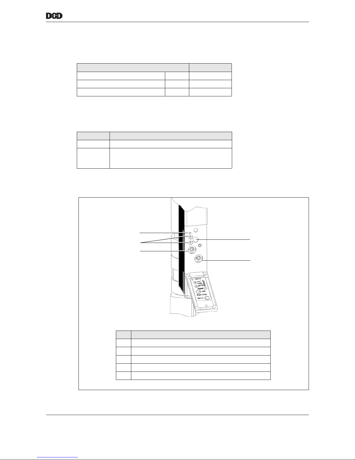
3
5
4
1
2
a00601.wmf
Item Designation
1 ARCNET address preset
2 "Active" LED
3 <Reset> button
4 DGD service interface (RS232) for measuring board (MC)
5 DGD service interface (RS232) for servo
Page 26
26 P2077SB/EN 2011-09 77f_Schraubmodul-en.fm, 06.09.2011
Tightening module TSE/TUSE
6
6.4.1 ARCNET address preset
The ARCNET address is preset via the two 10-stage decode switch.
Permitted settings 01 to 32.
• Switch (x1) for units (00-09),
• Switch (x10) for tens (00-30).
6.4.2 "Active" LED
The "Active" LED indicates which activities the ARCNET is performing.
6.4.3 <Reset> button
Press the <Reset> button to acknowledge faults. You will require a pointed object such as a ball-point pen.
Pressing this button resets the processor and reconfigures all functions.
6.4.4 DGD service interface (RS232) for measuring board (MC)
• Connection to PC via special cable
• Plug connector type: PS2
NOTES
• Always switch off the nutsetter control unit before making adjustments.
• Each address can be used only once in the system. Otherwise an error is triggered on the
mPro400GC-M.
Signal Activity
LED lights up Data transfer to the ARCNET
LED flashes ARCNET reconfiguration /
transfer is disrupted
LED off Internal fault /
no power available
NOTE
only for DGD service
Pin Signal Description
1 RxD ±10 V
2 TxD ±10 V
3 VCC 3.3 V ±2 % / 20 mA
4, 5, 6 - -
Housing GND 0 V
Page 27
77f_Schraubmodul-en.fm, 06.09.2011 P2077SB/EN 2011-09 27
Tightening module TSE/TUSE
6
6.4.5 DGD service interface (RS232) for servo
• Connection to PC via special cable
• Plug connector type: PS2
6.5 Internal assemblies
6.5.1 Power adapters
The internal power adapters supply power to all electronic assemblies in the tightening module.
• All generated voltages are short-circuit proof.
• Galvanic isolation of ARCNET output stage from all other power supplies.
• Pulse frequency of the converter is 80 kHz.
NOTE
only for DGD service
Pin Signal Description
1 RxD ±10 V
2 TxD ±10 V
3 VCC 3.3 V ±2 % / 20 mA
4 AMON Analog monitor, 0 V – 3.3 V
5 AIN Analog preset, 0 V – 3.3 V
6 START Start signal to servo, 0 V (start) / 3.3 V
Housing GND 0 V
Supply Generated
voltage
V
Maximum
current
A
Internal – servo section logic 3.3 (3.2 – 3.4) 0.5
Internal – servo section analog 5.0 (4.9 – 5.1) 0.5
Internal – servo section analog 15.0 (14.25 – 15.75) 0.12
Internal – measuring section logic 1.9 (1.78 – 2.02) 1
Internal – measuring section analog 2.5 (2.4 – 2.6) 1
Internal – measuring section analog 3.3 (3.2 – 3.4) 0.5
Internal – measuring section analog 12.0 (11.4 – 12.6) 0.5
Transducer 12.0 (11.8 – 12.2) 0.6
ARCNET output stage 5.0 (4.8 – 5.2) 0.2
Page 28
28 P2077SB/EN 2011-09 77f_Schraubmodul-en.fm, 06.09.2011
Tightening module TSE/TUSE
6
6.5.2 Motor end stage
• Short-circuit proof: phase – phase, phase – PE, phase – temperature monitor.
• Minimum losses due to IGBT end stage.
6.5.3 Measuring board
• Separate processors for measuring and communication tasks.
• A measuring channel for torque recording (2 tracks).
• Measuring software in FLASH memory.
The software is updated by the nutsetter control unit mPro400GC-M via the ARCNET.
• Press the button under the service panel to reset, see 6.4.3 <Reset> button, page 26.
• Torque measuring accuracy 0.2 %.
• Resolution 12 bits at ±6.6 V, therefore approx. 6.5 mV.
• Measurement sampling rate, 3300 measurements per second.
• Analog filter for torque signals 1 KHz.
• Current redundancy possible by measuring the motor current transferred by the servo amplifier.
• Measuring the motor angle signals transferred by the servo amplifier via the synchronous serial interface (SSIO). These are generated from the resolver signals.
Communication between measuring board and servo amplifier
• A synchronous serial interface (SSIO) provides a means of communication between the servo amplifier
and the measuring board.
• For safety reasons, the start signal is transferred from the measuring board to the servo amplifier both
via a separate input/output and via the SSIO.
Communication between CPS3 and mPro400GC-M
• The two units communicate via the ARCNET high-performance field bus.
• The transfer rate is 2.5 MBd.
Features Data
Intermediate circuit voltage U
Z
VDC 380 ±10 %
Excess voltage shut-off VDC > 480
Low voltage shut-off VDC < 160
Rated output at 50 °C VA 1000
Peak power, momentary VA 8000
Peak current, maximum A 65
Current-controlled shut-off, short circuit A 100
Efficiency % approx. 98
Pulse frequency of the PWM KHz 10
NOTE
The measuring board is a component of the tightening module and should not be replaced separately.
Page 29
77g_Komponenten-en.fm, 06.09.2011 P2077SB/EN 2011-09 29
Attachment
7
7 Attachment
7.1 Centric Attachment
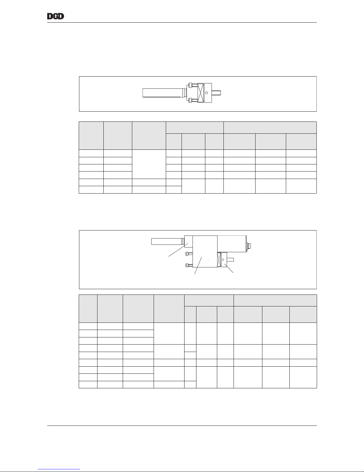
7.2 Offset attachment
Code Part no. Ratio
i
Permissible load
on output shaft
Lateral force at wrench head
1)
TQNmPres-
sure
1)
N
1) During continuous operation for long periods, multiply the specified values by 0.3
Ten-
sion
1)
N
Extended
N
25 mm
Retracted
N
50 mm
Retracted
N
1ZB 927222
1:1
53 1900 1500 1150 1350 1600
2ZB 927227 200 4500 3200 2450 2700 3250
3ZB 927233 300 6500 5000 3000 3500 4100
4ZA 927236 660 9000 8800 4300 4800 5400
4Z1250A S976950 3.7368 1250
9000 8800 4300 4800 5400
4Z1600A S976951 3.7368 1600
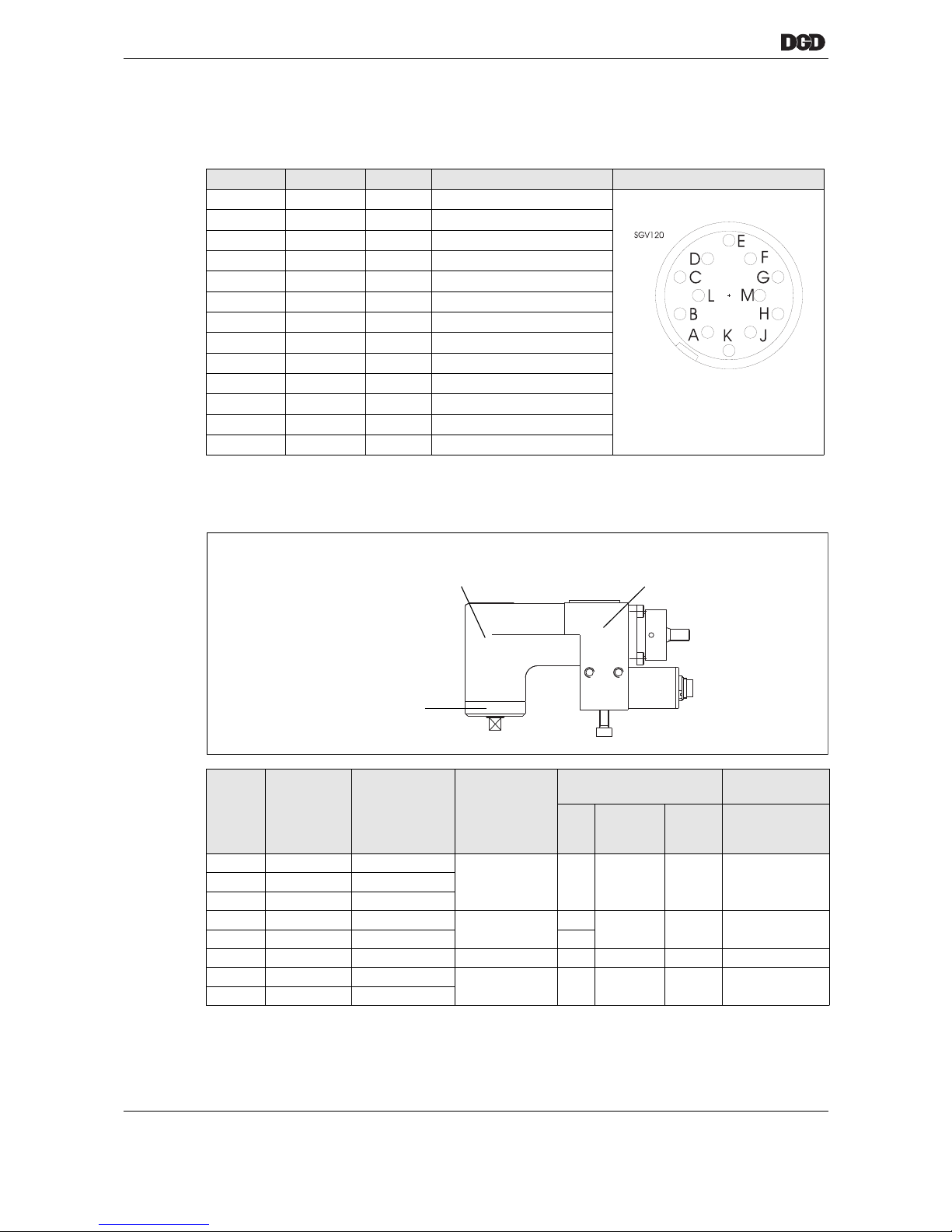
Code Part no. Torque
Calibration
Ratio
i
Permissible load
on output shaft
Lateral force at wrench head
1)
TQNmPres-
sure
1)
N
1) During continuous operation for long periods, multiply the specified values by 0.3
Ten-
sion
1)
N
Extended
N
25 mm
Retracted
N
50 mm
Retracted
N
1VM1B 935865PT 35
1.0526 53 2300 2300 1510 1720 20001VM2B 935864PT 60
1VM3B 935863PT 12
2VM1B 934336PT 110
1.0714
110
2500 2500 2300 2600 3100
2VM3B 934335PT 200 200
3VM2B
2)
2) On request
300 1.0769 260 3600 3600 2850 3250 3750
4VM2B 2) 500
1.0667 660
6300 2100 4300 4800 54004VM3B 2) 660
4VM4B 2) 900 1.2857 900
a00332_1.eps
Illustration of 1ZB
a00333_1.eps
Cap nut
Crown gearing
Helical spur gears
Range
torque measurement
Page 30
30 P2077SB/EN 2011-09 77g_Komponenten-en.fm, 06.09.2011
Attachment
7
7.2.1 Pin configuration of offset attachment
Type: 12-pin circular connector Lumberg SGR 120, Binder series 680 no. 09-0331-90-12
with locking connector in accordance with DIN 45 321
7.3 Angle head attachment
Pin Color Signal Description
A–– nc
B Brown – nc
C green TQ Torque output
D Yellow 0 VA 0 V torque reference connection
E gray 0 V 0 V supply
F Pink +12 V Supply
G Blue – nc
H Red RxD+ interface
Y Black RxD- interface
K Violet CAL Input calibration voltage
L Gray / pink TxD- interface
M Red / blue TxD+ interface
Housing PE Shield connection
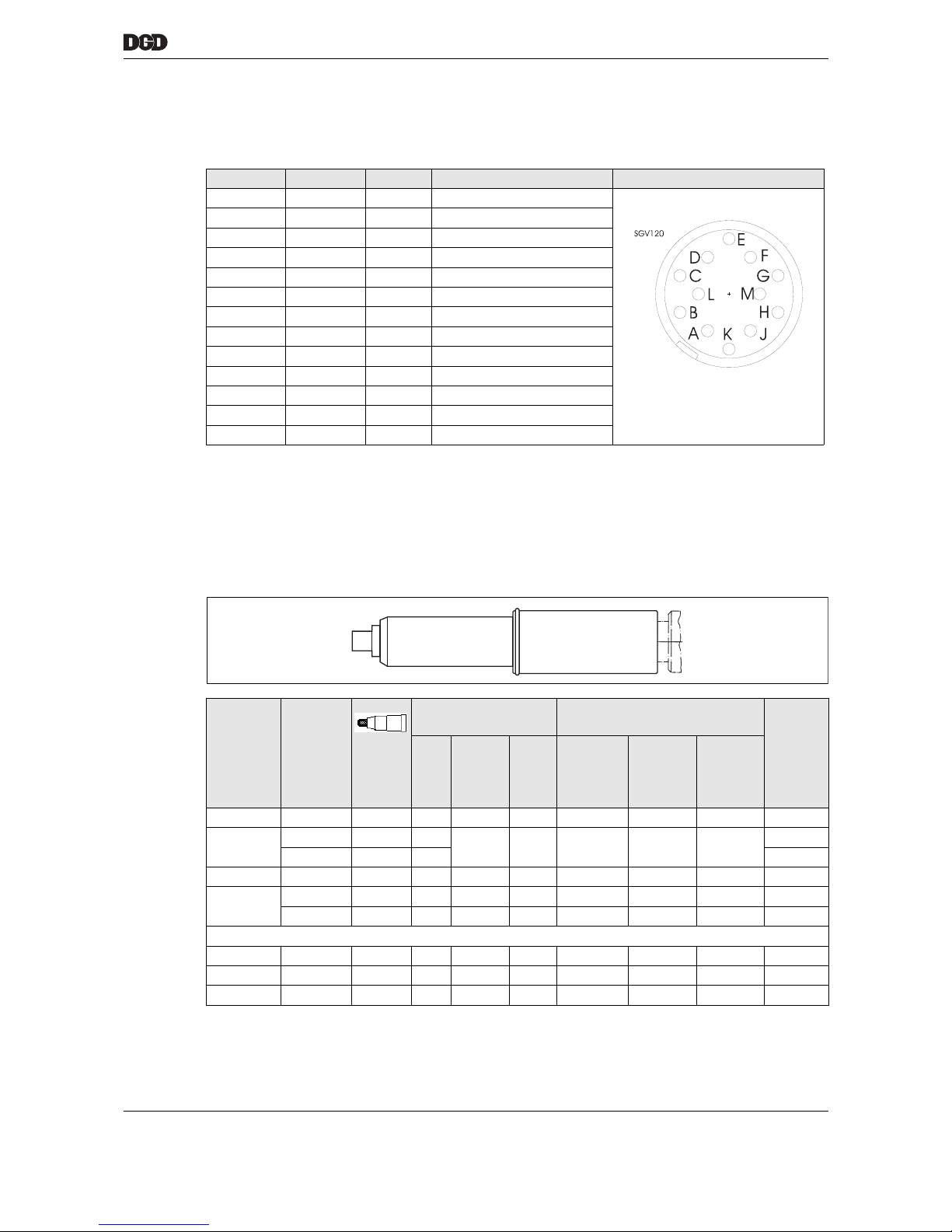
Code Part no. Torque
Calibration
Ratio
i
Permissible load
on output shaft
Lateral force
on square
1)
TQ
Nm
Pres-
sure
1)
N
1) During continuous operation for long periods, multiply the specified values by 0.3
Ten-
sion
1)
N N
1WM1B 934367PT 35
1.0667 53 1700 3400 31001WM2B 934368PT 60
1WM3B
2)
2) On request
12
2WM1B 934357PT 110
1.0625
110
1850 3900 4200
2WM3B 934374PT 200 200
3WM2B 2) 300 1.0385 300 3800 4800 5100
4WM2B 2) 500
1.0370 660 1200 6500 5900
4WM3B 2) 660
a00334_1.eps
Helix-toothed
bevel wheels
Cap nut
Crown gearing
Range
torque measurement
Page 31
77g_Komponenten-en.fm, 06.09.2011 P2077SB/EN 2011-09 31
Attachment
7
7.3.1 Pin configuration angle head attachment
Type: 12-pin circular connector Lumberg SGR 120, Binder series 680 no. 09-0331-90-12
with locking connector in accordance with DIN 45 321
7.4 Spring collet – Optional
7.4.1 For centric / offset attachment
Size 1 – 4
Pin Color Signal Description
A–– nc
B Brown – nc
C green TQ Torque output
D Yellow 0 VA 0 V torque reference connection
E gray 0 V 0 V supply
F Pink +12 V Supply
G Blue – nc
H Red RxD+ interface
Y Black RxD- interface
K Violet CAL Input calibration voltage
L Gray / pink TxD- interface
M Red / blue TxD+ interface
Housing PE Shield connection
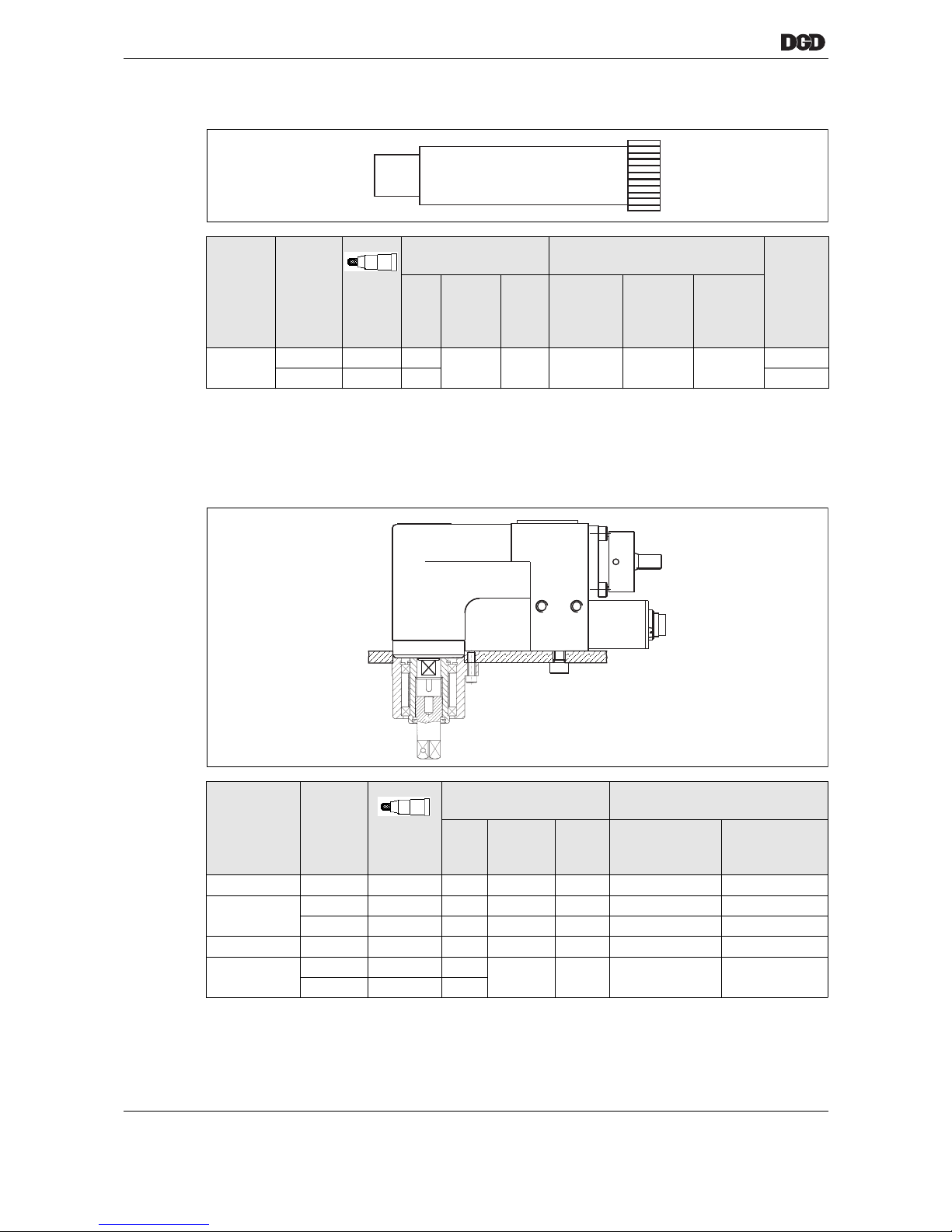
For Part no. Permissible load
on output shaft Lateral force at wrench head
1)
Weight
kg
TQ
Nm
Pres-
sure
1)
N
1) During continuous operation for long periods, multiply the specified values by 0.3
Ten-
sion
1)
N
Extended
N
25mm
Retracted
N
50 mm
Retracted
N
1Z… / 1V… 922325 3/8" 53 2300 1500 1510 1720 2000 0.33
2Z… / 2V…
910609 1/2" 110
4500 3200 2300 2600 3100
0.45
935553 3/4" 200 0,48
3Z… / 3V… 910613 3/4" 300 6500 5000 2850 3250 3750 0.67
4V…
912106 3/4" 500 9000 8800 4300 4800 5400 0.87
912147 1" 750 9000 8800 4300 4800 5400 0.90
including flange housing
1Z… S308434 3/8" 53 2300 1500 1510 1720 2000 0.65
2Z… S308435 1/2" 110 4500 3200 2300 2600 3100 1.05
3Z… S308436 3/4" 300 6500 5000 2850 3250 3750 1.80
Page 32
32 P2077SB/EN 2011-09 77g_Komponenten-en.fm, 06.09.2011
Attachment
7
Size 4Z..
7.4.2 For angle head including flange housing
Stroke of spring: 25 mm
For Part no. Permissible load
on output shaft Lateral force at wrench head
1)
Weight
kg
TQ
Nm
Pres-
sure
1)
N
1) During continuous operation for long periods, multiply the specified values by 0.3
Ten-
sion
1)
N
Extended
N
25mm
Retracted
N
50 mm
Retracted
N
4Z..
916643 3/4" 460
9000 8800 4300 4800 5400
1.21
916642 1" 630 1.24
For Part no. Permissible load
on output shaft
Lateral force at wrench head
1)
TQ
Nm
Pres-
sure
1)
N
1) During continuous operation for long periods, multiply the specified values by 0.3
Ten-
sion
1)
N
Extended
N
25mm
Retracted
N
1W.. 929041 3/8" 53 1700 6800 1800 2100
2W..
929053 1/2" 110 1850 6800 2500 3000
929061 3/4" 200 3800 7800 3000 3450
3W.. 929065 3/4" 300 3800 7800 3000 3450
4W..
929077 3/4" 500
12000 13000 4300 5050
929089 1" 660
a00335_1.eps
Page 33
77g_Komponenten-en.fm, 06.09.2011 P2077SB/EN 2011-09 33
Transducer
8
8 Transducer
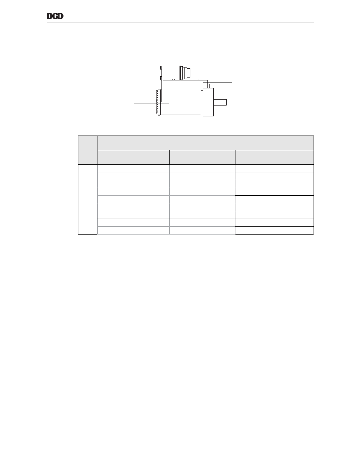
Size
Transducer
…M…
Code Part no. Capacity / calibration value
Nm
1 1M1B 934286PT 35
1M2B 934287PT 60
1M3B 934288PT 12
2 2M1B 934295PT 110
2M3B 934294PT 200
3 3M2B 934303PT 300
4 4M1B 934318PT 400
4M2B 934319PT 500
4M3B 936496PT 660
Evaluation electronics
Range
torque measurement
Page 34
34 P2077SB/EN 2011-09 77g_Komponenten-en.fm, 06.09.2011
Transducer
8
8.1 Electrical Data
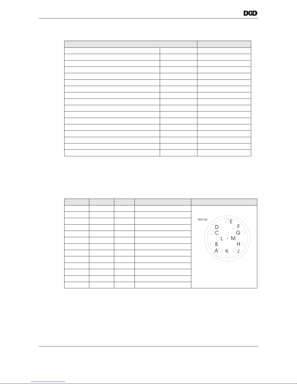
8.2 Pin configuration of transducer
Type: 12-pin circular connector Lumberg SGR 120, Binder series 680 no. 09-0331-90-12
with locking connector in accordance with DIN 45 321
Torque measurement features Data
Nominal supply voltage V +12
Supply voltage limits V +10.75...+12.5
Supply current mA 80
Measured output voltage – nominal voltage V -5…+5
Measured output voltage limits U
N
V ±5.000 ±0.5 % + U
0
Permitted measuring range of rated torque % ±10...±125
Zero voltage limit value U
0
mV ±100
Nonlinearity / Torque measurement % of U
N
±0.25
Measuring accuracy % of U
N
±0.5
Output current, maximum mA 5
Internal resistance Ri, torque output <10
Limit frequency of the torque measurement (-3dB) KHz 2
Measured output voltage calibration ON U
K
VU
N
±0.25%
Calibration voltage, input ON V > 3.5
Calibration voltage, input OFF V < 2.0
Calibration voltage, maximum V 35
Calibration input impedance K 5
Pin Color Signal Description
A–– nc
B Brown – nc
C green TQ Torque output
D Yellow 0 VA 0 V torque reference connection
E gray 0 V 0 V supply
F Pink +12 V Supply
G Blue – nc
H Red RxD+ Interface
Y Black RxD- Interface
K Violet CAL Input calibration voltage
L Gray / pink TxD- Interface
M Red / blue TxD+ Interface
Housing PE Shield connection
Page 35
77g_Komponenten-en.fm, 06.09.2011 P2077SB/EN 2011-09 35
Gearing
9
9 Gearing
10 Motor
10.1 Technical data
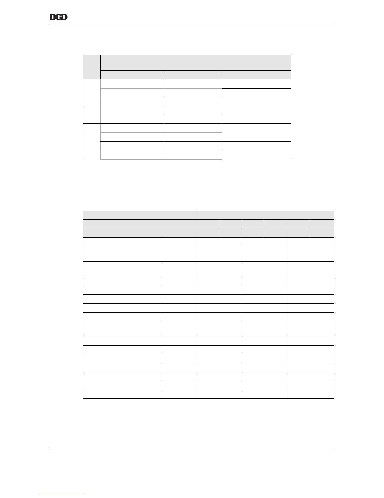
Size
Gearing
…B…
Code Part no. Ratio
1 1B012A 927346 5.7273
1B035A 927344 15.1364
1B060A 927345 25.7727
2 2B110A 935548 12.3595
2B200A 935549 21.9231
3 3B300A 935590 18.7500
4 4B360A 929541 26.3118
4B500A 935780 33.4219
4B660A 935781 48.9345
Features Data
Code 1BT 1BUT 2BT 2BUT 3/4BT 3/4BUT
Part no. 935560 935563 935561 935564 935562 935565
Speed, maximum
RPM
11000 11000 8500
Operating mode according to
VDE 0530
S 1 S 1 S 1
Enclosure type according to
DIN 40050
IP54 IP54 IP54
Sense of rotation Reversible Reversible Reversible
Design B14 B14 B14
Connection type Plug connector Plug connector Plug connector
Mass moment of inertia
kgm² × 10
-3
0.017 0.06 0.25
Rated torque
Nm
0.55 1.60 3
Permanent torque, maximum
at a stop
Nm
0.61 1.8 4
Peak torque
Nm
2.8 10.5 18.3
Speed change per torque
rpm / Ncm
1)
12.2 1.9 0.34
Mechanical time constants
ms
2.1 1.3 1.1
Friction torque
Nm
0.03 0.07 0.15
Rotor weight
kg
0.36 0.79 1.54
Motor weight
kg
1.6 3.1 6.5
Ball bearing
A/B side
6000/608 6200/6200 6202/6201
Page 36
36 P2077SB/EN 2011-09 77g_Komponenten-en.fm, 06.09.2011
Motor
10
10.2 Electrical Data
10.3 Thermal data
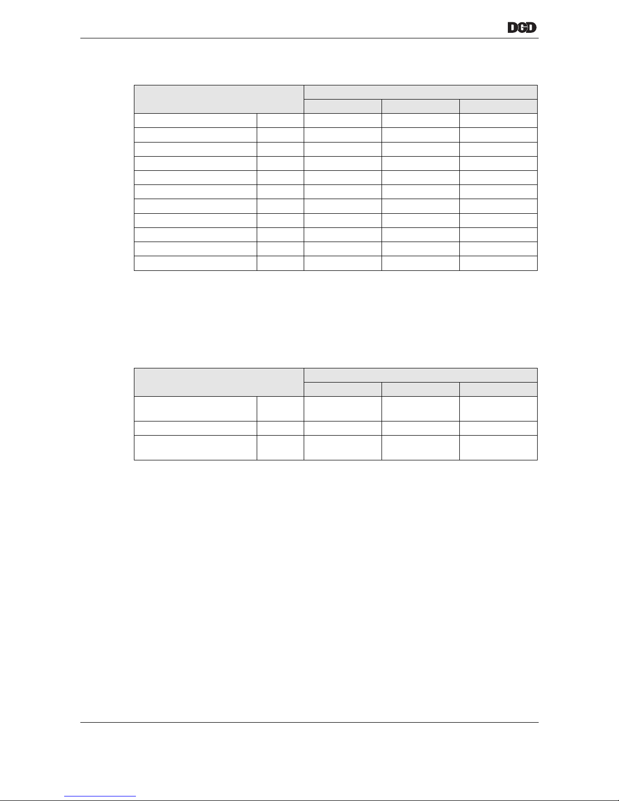
Features Data
1B(U)T 2B(U)T 3/4B(U)T
Intermediate circuit voltage V 380 380 380
Rated current
1)
1) Sine peak value
A 2.1 6 8.7
Rated output W 260 500 940
Number of phases 3 3 3
Terminating resistance
2)
2) Measured between two phases
Ohms 11 1.8 0.6
Inductance
2)
mH 6.5 3.1 2.4
Voltage constants
3)
3) -10 %
mV/RPM 34 34 44
Torque constant
3)
Nm/A 0.28 0.28 0.36
Current at peak torque
1)
A114459
Max. peak current
1) 4)
4) The values specified apply to operation within the temperature range of 0 - 40° C. They may not be exceeded, even
for a short period of time, since this would lead to the risk of a magnetic weakening.
A 205473
Electrical time constants ms 0.59 1.7 4
Features Data
1B(U)T 2B(U)T 3/4B(U)T
Insulation class
according to VDE 0530
FFF
Thermal time constants min 17.5 25 35
Temperature rise
without cooling
K/W 1.30 1.05 0.75
Page 37
77g_Komponenten-en.fm, 06.09.2011 P2077SB/EN 2011-09 37
Motor
10
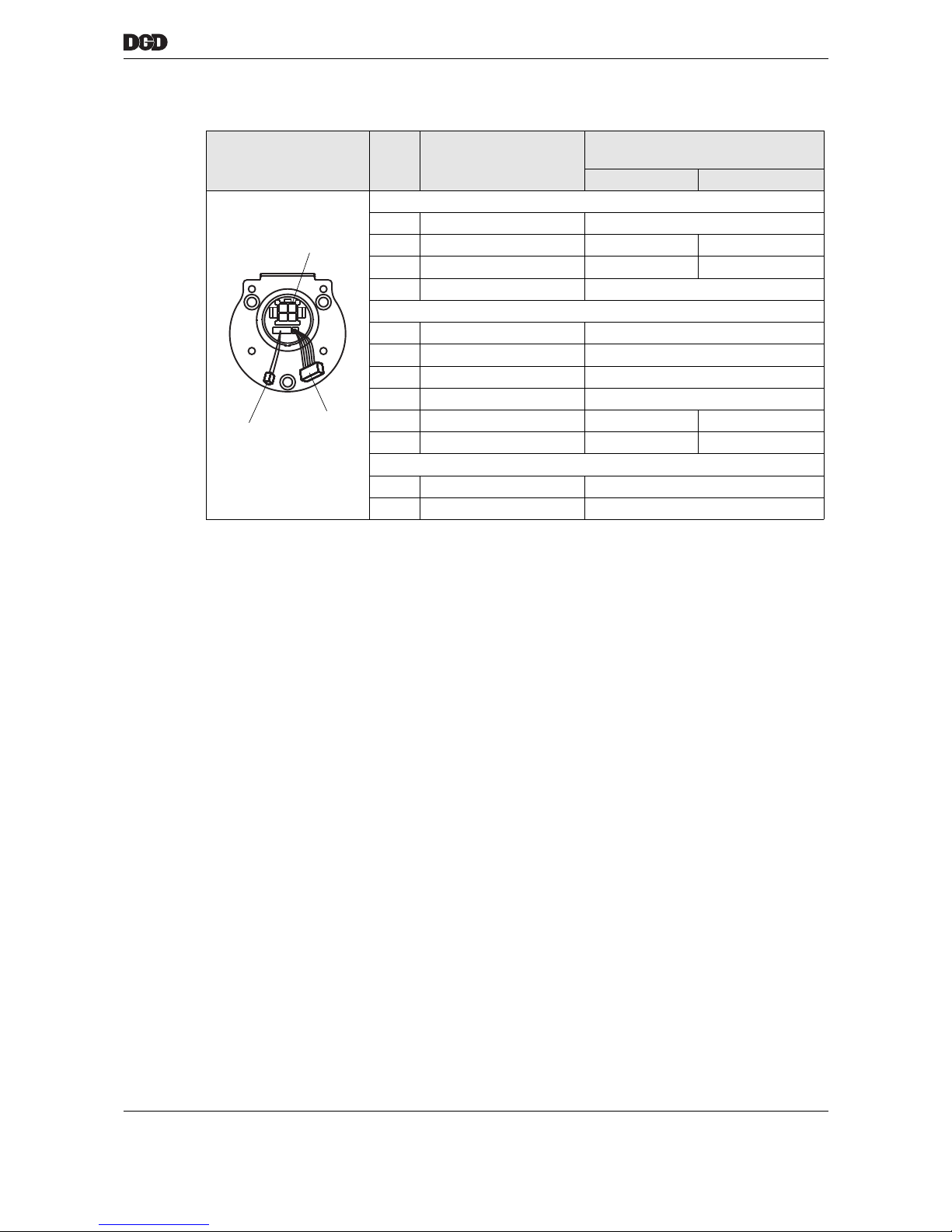
10.4 Pin configuration motor connector
Pin Signal designation Wire colors
(in motor)
Motor type BT Motor type BUT
Motor (1)
4 PE Green/yellow
1 Phase S green green
2 Phase R Black Red
3 Phase T red/black
Resolver (2)
1 Resolver R1 Red/white
2 Resolver R2 Yellow/white
3 Resolver S1 Red
4 Resolver S3 Black
5 Resolver S2 Yellow Blue
6 Resolver S4 Blue Yellow
Temperature sensor (3)
1 0 V Black
2 Signal Red
1
2
3
Page 38

38 P2077SB/EN 2011-09 77g_Komponenten-en.fm, 06.09.2011
Motor
10
Blank page
Page 39
77h_PowerDistributionBox-en.fm, 06.09.2011 P2077SB/EN 2011-09 39
Power distribution box PDB-CPS…
11
11 Power distribution box PDB-CPS…
11.1 Brief function description
Power distribution box PDB-CPS… supplies the tightening module TSE/TUSE with 380 VDC (CPS3) and
24 VDC.
The machine control unit transmits the signals Control on and Emergency stop. These switch the intermediate circuit voltage for the DGD-IS on and off.
The integrated emergency stop safety relay PNOZ X3P activates and monitors two relays. The relays
activate the supply voltage.
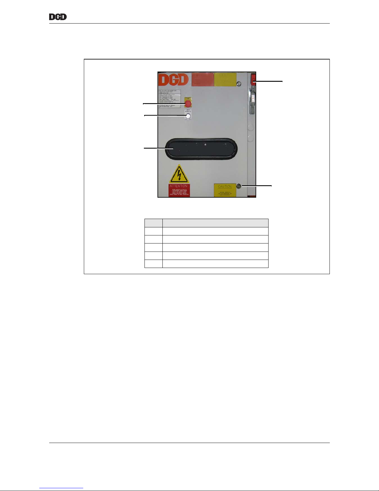
1
77_power-distribution-box_front.png
Item Designation
1 Rotary switch
2 Seal
3 Supply module CPS3 (integrated)
4 "Ready" indicator
5 Emergency stop
5
3
4
2
Page 40
40 P2077SB/EN 2011-09 77h_PowerDistributionBox-en.fm, 06.09.2011
Power distribution box PDB-CPS…
11
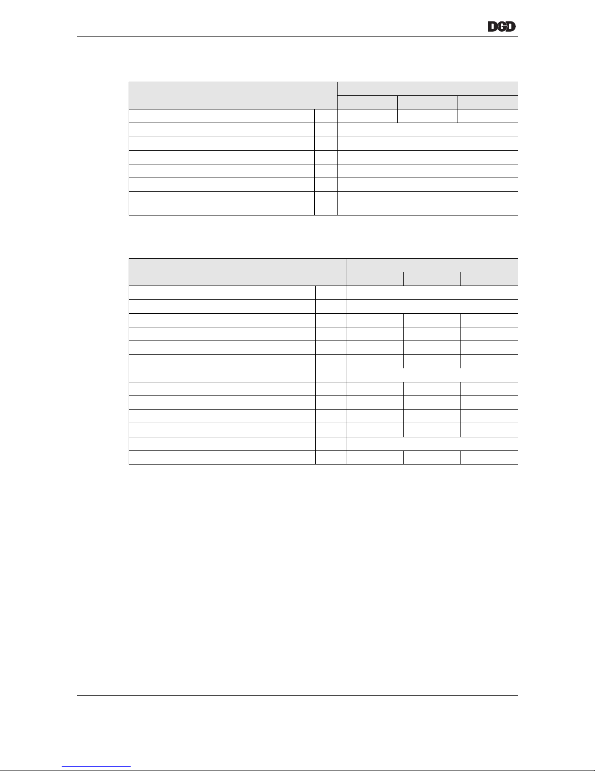
11.2 General technical data
11.3 Electrical Data
11.3.1 Intermediate power circuit 380 VDC
The intermediate power circuit supplies the DGD-IS with 380 VDC.
• A safety isolating transformer converts the supply voltage to 3× 270 VAC, which is then supplied to the
CPS3.
• The processor controls two integrated relays that limit the switch-on current. The main relay switches on
after the system initializes. The intermediate circuit capacitors are charged via a resistor until the intermediate circuit voltage reaches approx. 380 VDC. The resistor is then bridged via a start-up relay.
• Energy is generated when the motor brakes, which causes the voltage to increase. The braking chopper
with braking resistor integrated in the CPS3converts the excess energy into heat.
• When the circuit is switched off, the intermediate circuit capacitors is discharged via the braking resistor.
Features Data
PDB-CPS3 PDB-CPS6 PDB-CPS9
Weight lbs 125 140 155
Protection category IP54
Cooling type Convection (self-cooling)
Service life, operating h 40.000
Usability period if stored h 100,000 (approx. 11 years)
On/Off switching cycles 5.000.000
Safety requirements in accordance with
EN 964-1
Category 4
Features Data
PDB-CPS3 PDB-CPS6 PDB-CPS9
Supply voltage VAC 3 × 480 ±10%
Frequency Hz 50-60
Rated current A 3 x 4 3 x 8 3 x 12
Peak current, momentary A 3 x 20 3 x 40 3 x 60
Rated output VA 3000 6000 9000
Peak power, momentary VA 30.000 60.000 90.000
Output voltage of intermediate power circuit VDC 380 ±10 %
Nominal output current (380 VDC) A 8 16 24
Output current, maximum (5 s) A 80 160 240
Circuit breaker, 3-pin A 32 32 50
Tripping characteristic C D D
Control voltage / Output voltage VDC 24 ±10 %
Output current, maximum (24 VDC) A 5 10 20
Page 41
77h_PowerDistributionBox-en.fm, 06.09.2011 P2077SB/EN 2011-09 41
Power distribution box PDB-CPS…
11
11.4 Installation
➔ Secure the PDB-CPS… to the machine using 4 x M8 8.8 screws (Tq = 25 Nm).
11.4.1 Guidelines
The PDB-CPS… is ventilated by a natural convection system, an active fan is not required.
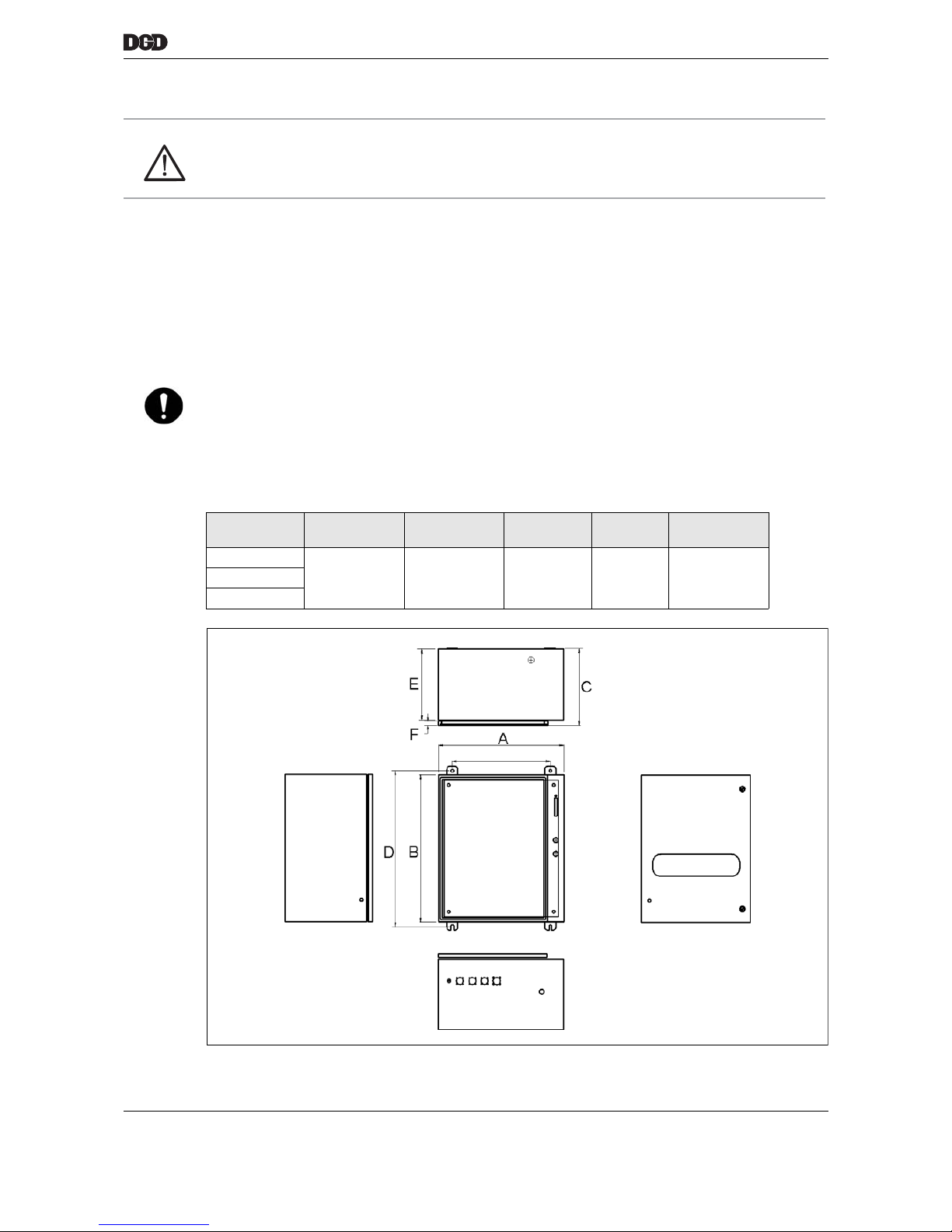
Dimensions / drilling pattern
WARNING!
Unplugging the system cable while still live may generate an electric arc and cause serious burns. The contacts may become damaged.
➔ Switch off the power supply to the PDB-CPS… before unplugging or inserting the system cable!
NOTE
➔ Warm air must not enter below the housing.
➔ No objects are allowed to obstruct the air flow below and above the housing
(see hatching in the graphic Dimensions / drilling pattern, page 41).
➔ The PDB-CPS… should not be exposed to direct sunlight.
Power distri-
bution box
A
mm (")
B
mm (")
C
mm (")
D
mm (")
E
mm (")
PDB-CPS3
584 (23.00) 686 (27.00) 356 (14.00) 724 (28.50) 330 (13.00)PDB-CPS6
PDB-CPS9
77_power-distribution-box_Masse.png
Page 42
42 P2077SB/EN 2011-09 77h_PowerDistributionBox-en.fm, 06.09.2011
Power distribution box PDB-CPS…
11
11.5 Supply module CPS3
11.5.1 Description
The supply module CPS3 (Central Power Supply 3 KVA) is integrated in the power distribution box
PDB-CPS:
• 1× in PDB-CPS3
• 2× in PDB-CPS6
• 3× in PDB-CPS9
The CPS3 has the following functions:
• Rectification and smoothing of the intermediate circuit voltage to 380 VDC for the tightening module
TSE/TUSE
• Switch-on current limiting
• Braking chopper
• Excess and low-voltage monitoring with intermediate circuit shut-off
• Short circuit and overcurrent monitoring
• Generation of Ready signal on the mPro400GC-M and machine control
• Evaluation of signal Emergency stop
a00639.wmf
Page 43
77h_PowerDistributionBox-en.fm, 06.09.2011 P2077SB/EN 2011-09 43
Power distribution box PDB-CPS…
11
11.5.2 General technical dataCPS3
11.5.3 Electrical DataCPS3
Features Data
Order No. 961112
Weight G 3650
Protection category IP20
Cooling type Convection
(self-cooling)
Service life, operating h 40.000
On/Off switching cycles 5.000.000
Usability period if stored h 100,000 (approx. 11 years)
Features Data
Supply voltage power VAC 3 × 270 ±10%
Frequency Hz 50 – 60
Rated current A 3 × 7
Peak current, momentary in RMS mode A 3 × 25
Rated output VA 3000
Peak power, momentary in RMS mode VA 30.000
Output voltage of intermediate power circuit VDC 380 ±10 %
Nominal output current (380 VDC) A 8
Output current, maximum (5 s) A 80
Control supply voltage VDC 24 ±10 %
Input current (without external load) A 0.5
Control voltage / Output voltage VDC 24 ±10 %
Output current, maximum (24 VDC) A 8
Page 44
44 P2077SB/EN 2011-09 77h_PowerDistributionBox-en.fm, 06.09.2011
Power distribution box PDB-CPS…
11
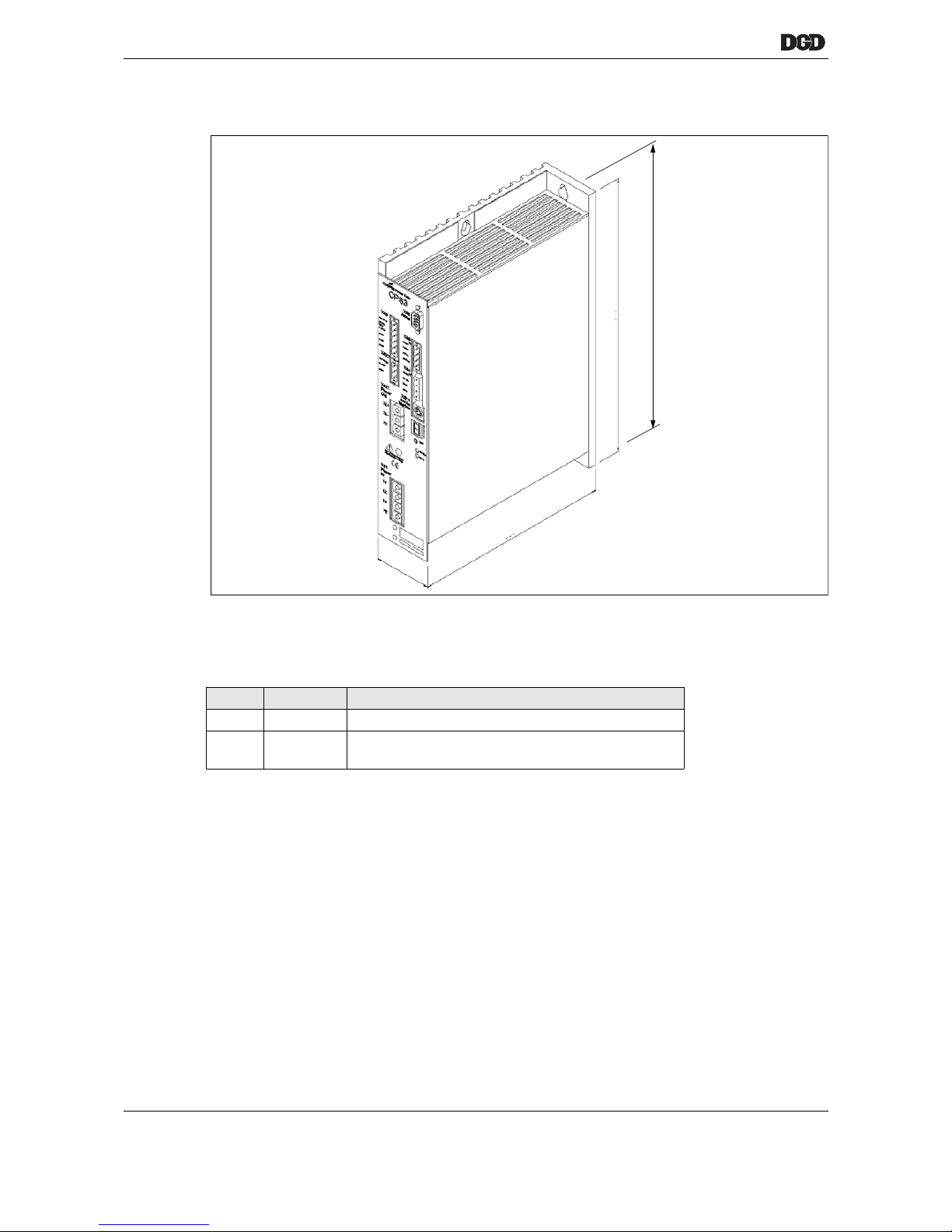
11.5.4 Size
11.5.5 Indicators
LED
7-segment "Status" display
Error indicators, see 15.3.3 7-segment "Status" display, page 66.
11.5.6 <Reset> button
Press the <Reset> button to acknowledge faults. You will require a pointed object such as a ball-point pen.
Pressing this button resets the processor and reconfigures all functions.
Signal LED CPS3
Green "Ready" Ready for operation
Red "EM stop" Emergency stop or Control on signal unavailable. The
intermediate power circuit (380 VDC) is deactivated.
200
280
a00638.wmf
60
260
Retaining holes
Page 45
77h_PowerDistributionBox-en.fm, 06.09.2011 P2077SB/EN 2011-09 45
Power distribution box PDB-CPS…
11
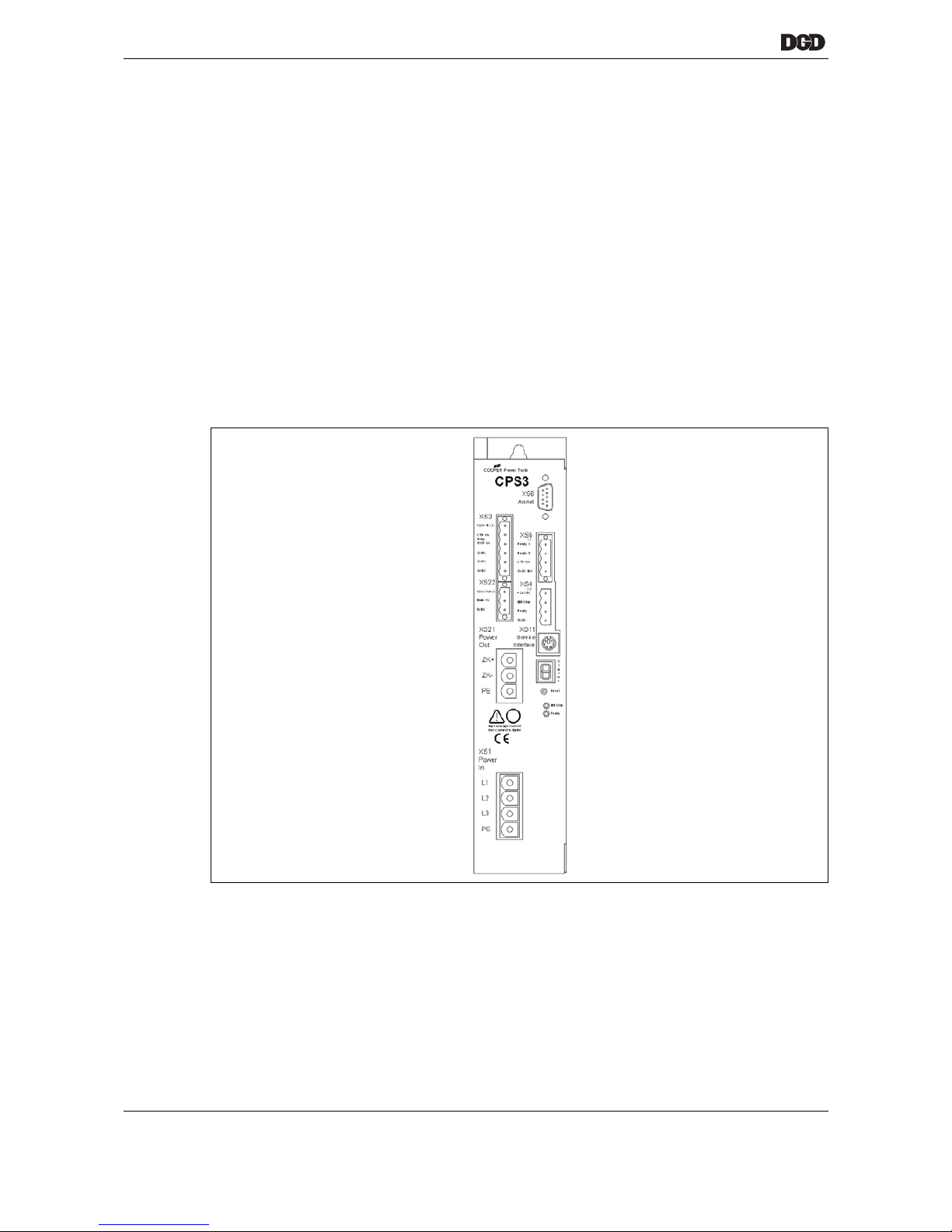
11.5.7 Plug connectors and configuration
"XS1 Power in"
Required connector type:
Phoenix Power Combicon PC6/4-ST-10,16
Order No. 961175
"XS21 Power out"
Power supply DGD-IS 380 VDC
Required connector type:
Phoenix Power Combicon IPC6/3-ST-10,16
Order No. 961188
"XS22" TSE/TUSE
24 V supply and Enable servo signal (end stage release signal) to DGD-IS
Required connector type:
Phoenix Combicon MSTB2.5/3-STF-5.08
Part no. S959935
WARNING!
• Unplugging the system cable while still live may generate an electric arc and cause serious burns.
• The contacts may become damaged.
➔ Switch off the power supply to the PDB-CPS… before unplugging or inserting the system cable!
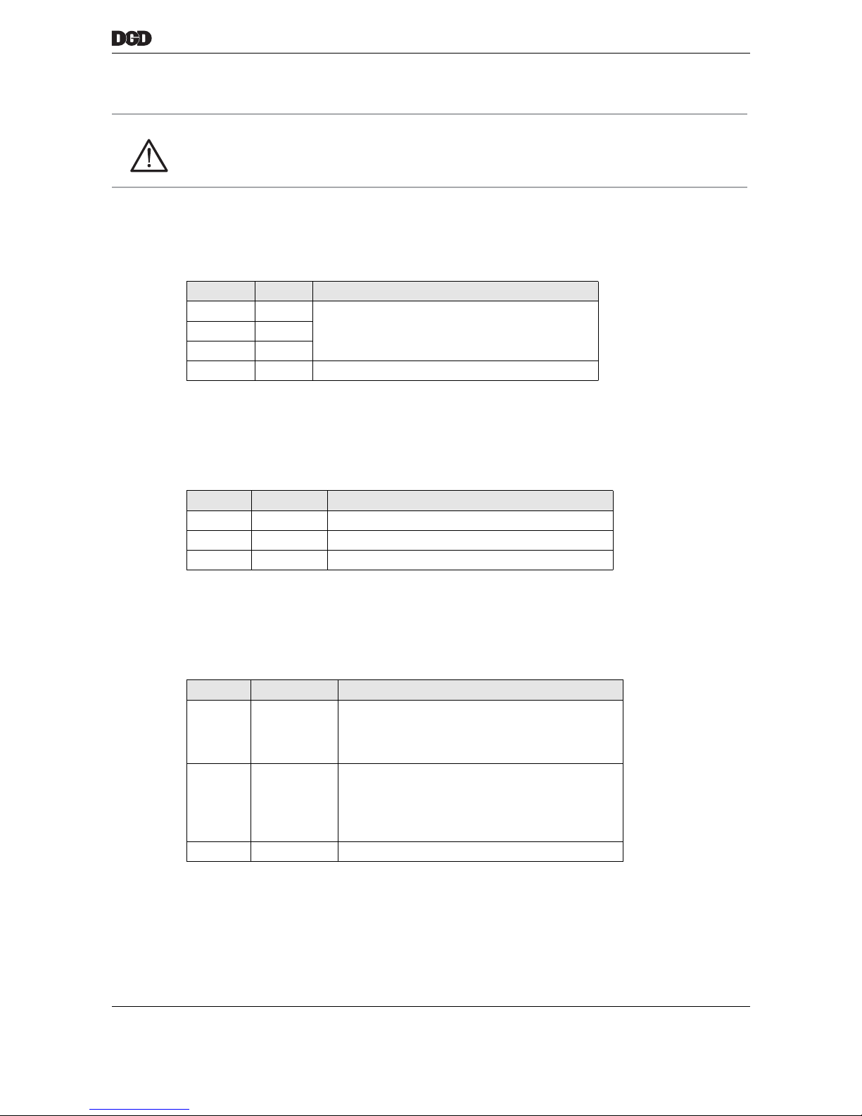
Contact Signal Description
L1 L1
Supply voltage 3 × 270 VACL2 L2
L3 L3
PE PE Earth conductor, connection to housing
Contact Signal Description
IC+ +380 VDC Intermediate circuit voltage +380 VDC ±10 %
IC- 0 VDC Intermediate circuit voltage 0 V
PE PE Earth conductor, connection to housing
Contact Signal Description
24 V +24 V Out Supply TSE/TUSE,
24 V +10 %,
max. 4 A
(8 DGD-IS)
Enab SV Enable servo Enable servo output;
End stage release;
Active when no errors or
Emergency stop pending
24 VDC, max. 0.3 A
0VDC 0V Supply TSE/TUSE, 0 V
Page 46
46 P2077SB/EN 2011-09 77h_PowerDistributionBox-en.fm, 06.09.2011
Power distribution box PDB-CPS…
11
"XS3" Logic supply and control-on relay output
24 V supply for the CPS3 and control on relay connection for the power supply
Required connector type:
Phoenix Combicon MSTB2.5/6-STF-5.08
Order No. 961177
"XS4" mPro400GC-M
Emergency stop signal from the mPro400GC-M and Ready signal to the mPro400GC-M
Required connector type:
Phoenix Combicon IC2.5/4-STF-5.08,
Order No. 961178
»XS5« machine control
Emergency stop signal from the machine control and Ready signal to the machine control
Required connector type:
Phoenix Combicon MSTB2.5/4-STF-5.08,
Order No. 961179
"XS6" ARCNET
The CPS3 is not equipped with ARCNET.
Contact Signal Description
+24 V IN (1) +24 V IN Supply of the logic in the CPS3,
24 V +10 %
CTR on
relay
CTR on
relay
Control-on output
for external relay 24 VDC, max. 0.3 A
PWR on PWR on Power on output,
24 VDC, max. 0.3 A
0 VDC 0 VDC
0 V of 24 V0 VDC 0 VDC
0 VDC 0 VDC
Contact Signal Description
+24 VDC +24 VDC Supply output, 24 V, max. 2 A
EM stop Emergency
Stop
Emergency stop input from mPro400GC-M
Ready Ready for
operation
Ready output to the mPro400GC-M, 24 VDC,
max. 0.3 A
0 VDC 0 VDC 0 V
Contact Signal Description
Ready 1 Ready for
operation
Relay contact 1
Ready output, relay contact 1, max. 26 V,
max. 100 mA
Ready 2 Ready for
operation
Relay contact 2
Ready output, relay contact 2, max. 26 V,
max. 100 mA
CTR on Control on Control on or Emergency stop input, 24 V, 10 mA
0 VDC Ext 0 VDC Ext 0 V from input
Page 47
77h_PowerDistributionBox-en.fm, 06.09.2011 P2077SB/EN 2011-09 47
Power distribution box PDB-CPS…
11
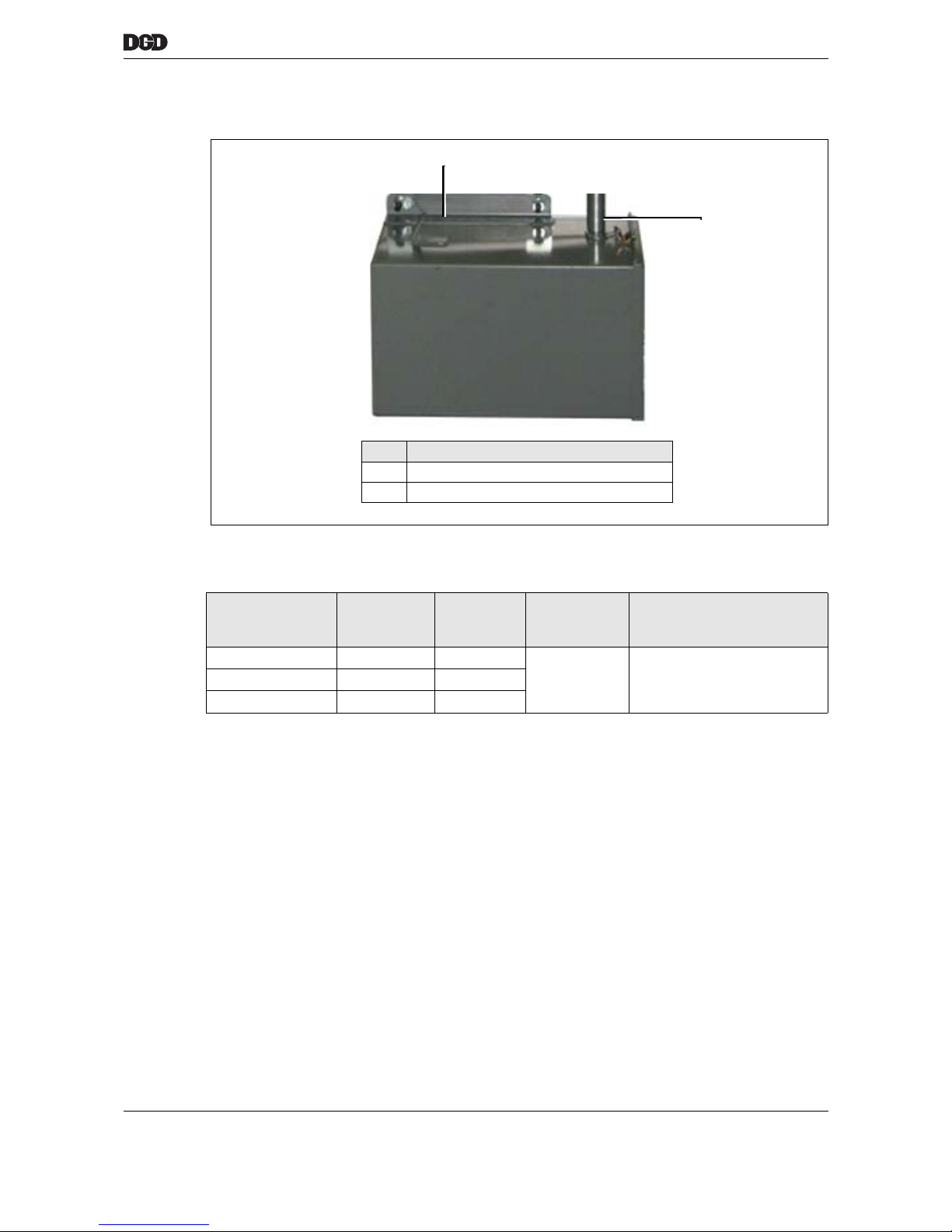
11.6 Transformer
11.7 General technical data
Part no. Power
Nominal
KVA
Weight
lbs
Protection
category
Type
CP3-3750-JH 3 125
IP54
Dry type, class AA,
encapsulated NEMA 1
CP3-6750-JH 6 150
CP3-9750-JH 9 200
1
77_power-distribution-box_front.png
Item Designation
1 Connection to PDB-CPS…
2 Bracket for mounting on wall / machine
2
Page 48
48 P2077SB/EN 2011-09 77h_PowerDistributionBox-en.fm, 06.09.2011
Power distribution box PDB-CPS…
11
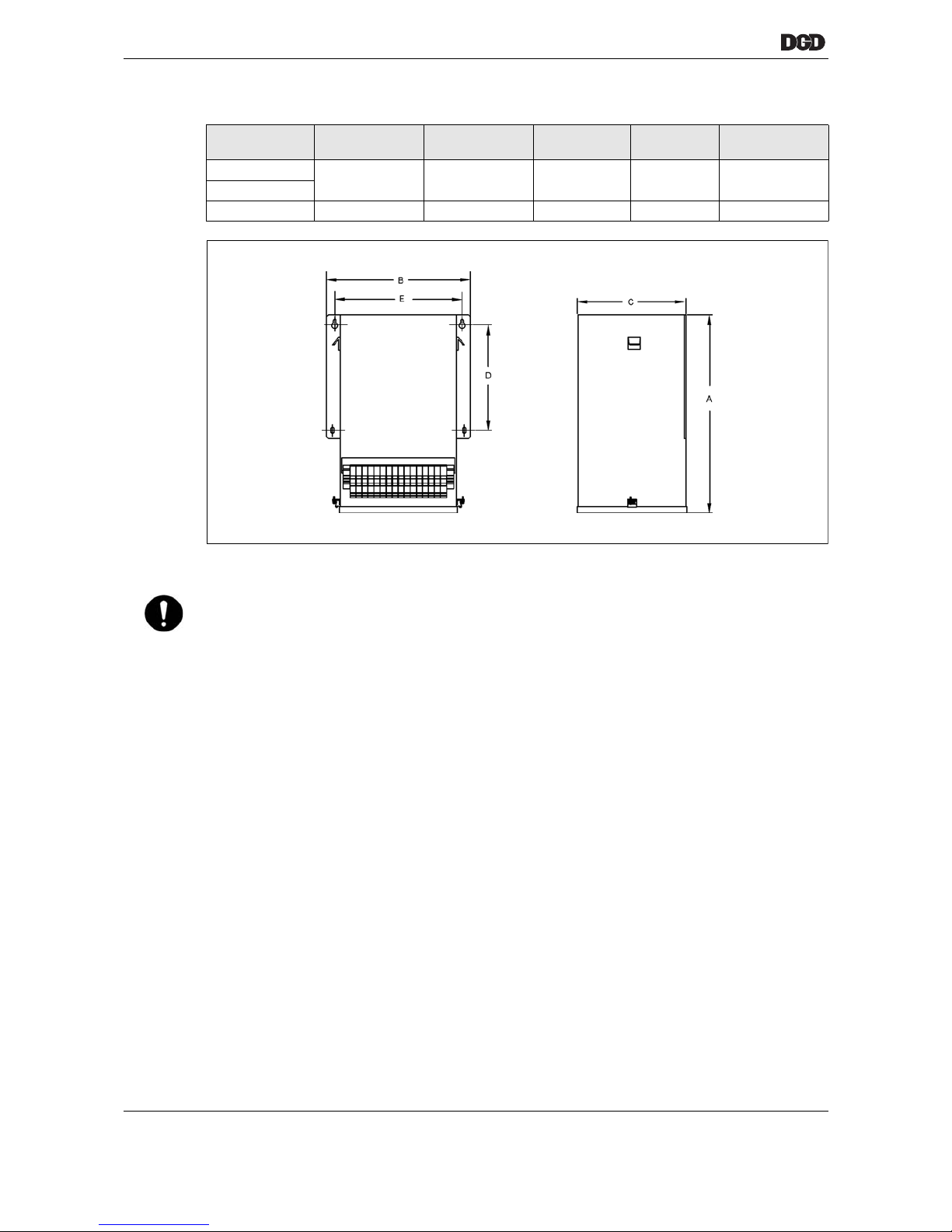
Dimensions / drilling pattern
Transformer A
mm (")
B
mm (")
C
mm (")
D
mm (")
E
mm (")
CP3-3750-JH3
387 (15.25) 314 (12.38) 229 (9.00) 286 (11.25)) 454 (8.50))
CP3-6750-JH6
CP3-9750-JH9 406 (16.00) 486 (19.12) 222 (8.75) 216 (8.50) 216 (17.88)
NOTE
➔ When installing, keep a distance of 25.4 mm from voltage-conducting components.
77_trafo_Masse.png
Page 49
17i_Kabel en.fm, 06.09.2011 P2077SB/EN 2011-09 49
Instructions on laying cables
12
12 Instructions on laying cables
12.1 General
➔ Don't bend cables while unrolling them. Don't create any loops or twists.
➔ Remember that a strain relief clamp and compression set must be incorporated within the bending
radius.
➔ Don't use extra-long cables and wires (reserve). Avoid mutual interference.
➔ Lay so-called "hot" and "cold" signal lines separately.
For this, use cable ducts in the control cabinet that are physically separated from each other.
Hot signal lines System cable, mains, nutrunner control power supply, cooling unit
Cold signal lines 24 VDC, PE, ARCNet cable, bus cable,
separate cables from transducers
CAUTION!
There is a risk of tripping or falling over loose cables on the ground.
➔ Lay all connected cables safely.
NOTE! ➔ Only cable types approved by Apex Tool Group may be used.
➔ Remember that the maximum total cable length is 50 m.
➔ Take appropriate measures to limit cable bending radii and torsion. Obverse the respective allowed
bending radii and torsional lengths.
➔ All plug connections must be closed. The locks must be tightened. The red ring around the outer diam-
eter of plug connectors with a slide lock should not be visible.
Page 50
50 P2077SB/EN 2011-09 17i_Kabel en.fm, 25.10.2011
Instructions on laying cables
12
12.2 Strain relief clamp
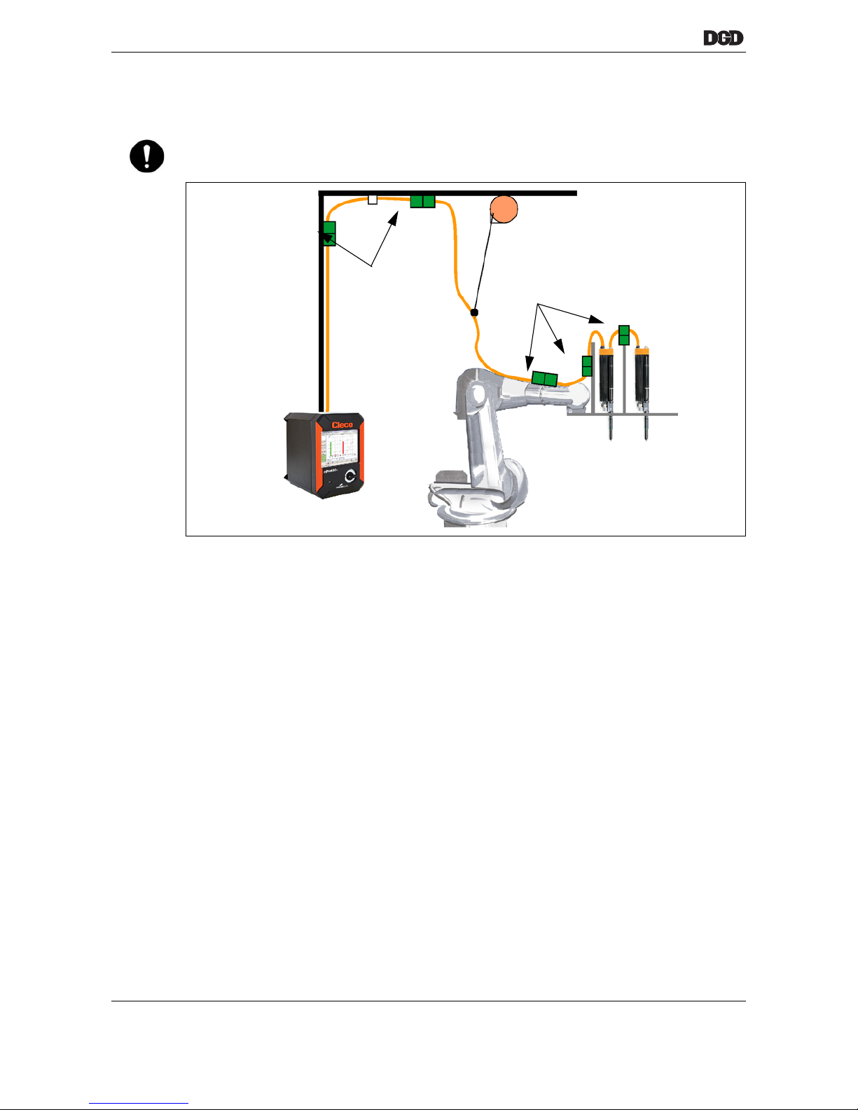
Fig. 12-1: Use with robot (example, other installations possible)
➔ Position the strain relief clamps so that the cables have maximum freedom of movement. Lay cables in
slight loops such that the cables never become strained when the cable drag chain is pulled out. Cable
pulls between the carriages or end stops on the rail can be of assistance.
We recommend: Run a few motion cycles after the initial installation of cables. Afterwards, check the cable
installation once more and optimize it if possible.
➔ Only secure cables with strain relief clamps designed for the corresponding cable diameter. Use screw-
on cable clips if possible. The clamping surface should be adjusted to the occurring tensile load. Too
narrow of a clamping surface may cause the cable to fail prematurely.
➔ Avoid crushing individual wires or subcomponents.
We recommend applying a clamping force around the entire circumference of the cable.
➔ Only secure the cables at the strain relief clamp.
➔ A secure strain relief clamp prevents the cable from shifting inside the flexible cable duct.
12.3 Shielding
The shielding in the lines limits the expansion of perturbation energy into the surroundings and shields the
system against disturbances.
The cables between tightening module and Built-in nutrunner or hand tool are shielded against exterior disturbances. However, this measure also counteracts interference emissions.
➔ Generally connect it to both ends.
➔ Extensively connect the shielding of the nutrunner cables (skin effect) to the lower edge of the tightening
module housing with the aid of shield connecting elements.
NOTE! ➔ Generally all cable and hose components must be provided with traction reliefs at the beginning and
end of the sections so that no tensile stresses can occur at connectors, plugs and rundowns.
Strain relief clamp
Strain relief clamp
Page 51
17i_Kabel en.fm, 06.09.2011 P2077SB/EN 2011-09 51
Instructions on laying cables
12
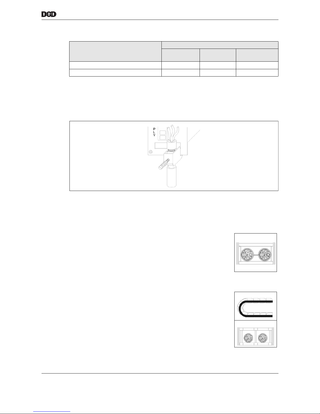
For this, use the following shield clamps:
The shielding in the transducer line is connected to the connector housing. The front panel of the measuring
board is grounded via the STM housing and ensures good shielding connection.
➔ Maximum unshielded area of the motor line, between shield end and plug connection on tightening mod-
ule = 50 mm.
➔ On the Built-in nutrunner or hand tool, extensively connect the shield to the metal housing of the plug
connection.
Fig. 12-2
12.4 Laying "High-Flex Quality" cables in cable ducts
The laying of lines and protection hoses in cable ducts must be carried out with the greatest possible care.
Generally, the following points must be observed:
Cables Shield clamp
Order No. Phoenix
Name
Phoenix
Item number
DGD-IS cable, BTS series S961062 SK14 30 25 17 6
Hand tool cable S961062 SK14 30 25 17 6
➔ The cables should lie free of twists in the cable duct.Prior to assembly, lay the
cables on an even surface so that they can be inserted while stretched out.
➔ Lay the cables in the cable duct individually, lying loosely adjacent to each other
whenever possible. Lay a maximum of 2 cables per partition.
➔ Separate cables lying adjacent to each other using cut-off bridges whenever
possible.
➔ Don't bundle cables or fasten them with cable ties.
➔ Never lay cables with different diameters (> 3 mm) together in the same parti-
tion.
➔ Cables must be able to follow the radius of curvature without being forced
around it.
Vertical installation:
➔ Leave about 20% clearance within the partition height. The lines hang out
downward due to the cable weight, including the chain. This lengthening due to
sagging must be monitored at regular intervals and adjusted if necessary.
a00253_1.wmf
System cable
Page 52

52 P2077SB/EN 2011-09 17i_Kabel en.fm, 06.09.2011
Instructions on laying cables
12
12.5 Wiring of robot area »SuperhighFlex Quality«
In order to achieve an optimal service life of cables in robotics applications, comply with the following points
when laying the cables:
➔ Avoid using cable binders to fasten cables.
➔ Lay the cable duct so that the cables have maximum freedom of movement.
➔ Lay the cables so that the sleeves do not rub during operation.
Cables should not knock against static parts or hang loose.
➔ Cables should not shift during operation.
➔ Do not exceed the minimum specified bending radii.
The size of the bending radius is proportional to length of the service life.
➔ Make sure that the length of the cable compensates for torsional loads.
Page 53
17i_Kabel en.fm, 06.09.2011 P2077SB/EN 2011-09 53
Cable
13
13 Cable
13.1 HighFlex Quality, suitable for cable ducts
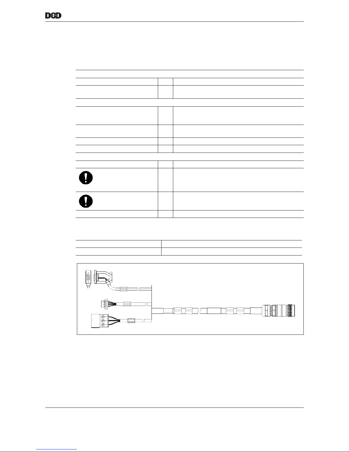
13.1.1 System cable, type C
Thermal properties
Ambient temperature °C -20…+80
Flammability Flame-retardant and self-extinguishing in accordance with
EN 50265-2-1, IEC 60332-1 and UL1581
Chemical properties of the coating
Coating material PUR, low-adhesion, resistant to hydrolysis and microbes,
UV-resistant, abrasion-resistant, tear-resistant, cut-resistant,
notch-resistant
Oil resistance Oil-resistant in accordance with DIN VDE 0472, part 803
ASTM oil 1 to 3 and HD 505.2.1
Resistance to hydrolysis In accordance with VDE 0283, part 10
Color RAL 2003 matt
Mechanical properties
Diameter mm approx. 13,8
Bending radii:
Single bends
Multiple bends
mm
30 min.
95 mm min. flexing action
130 min alternate bending
Torsional length
(±180 ° around separate
central axis)
mm 500 min.
Max. acceleration m/s² 100
Use Nutrunner control unit – DGD-IS
Order No. 961109-××× (…-××× = cable length in dm)
Page 54
54 P2077SB/EN 2011-09 17i_Kabel en.fm, 06.09.2011
Cable
13
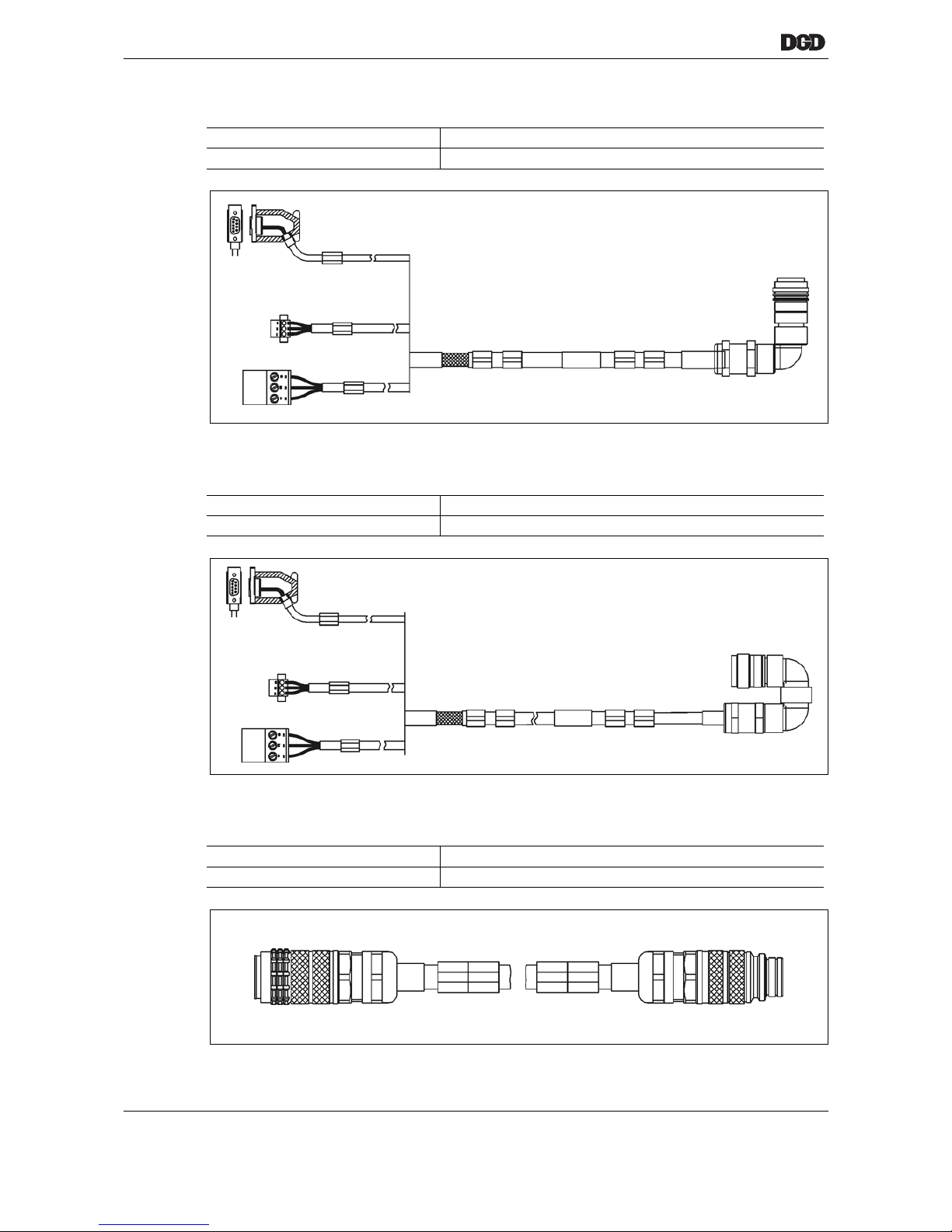
13.1.2 System cable, type I
13.1.3 System cable, type J
13.1.4 System cable, type A
Use Nutrunner control unit – DGD-IS
Order No. 961294-××× (…-××× = cable length in dm)
Use Nutrunner control unit – DGD-IS
Order No. 961289-××× (…-××× = cable length in dm)
Use Intermediate plug position – DGD-IS
Order No. 961104-××× (…-××× = cable length in dm)
Page 55
17i_Kabel en.fm, 06.09.2011 P2077SB/EN 2011-09 55
Cable
13
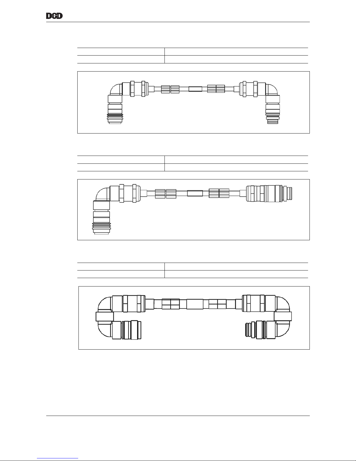
13.1.5 Jumper cable, type E
13.1.6 Jumper cable, type F
13.1.7 Jumper cable, type G
Use DGD-IS – DGD-IS
Order No. 961299-××× (…-××× = cable length in dm)
Use DGD-IS – DGD-IS
Order No. 961295-××× (…-××× = cable length in dm)
Use DGD-IS – DGD-IS
Order No. 961298--××× (…-××× = cable length in dm)
Page 56
56 P2077SB/EN 2011-09 17i_Kabel en.fm, 06.09.2011
Cable
13
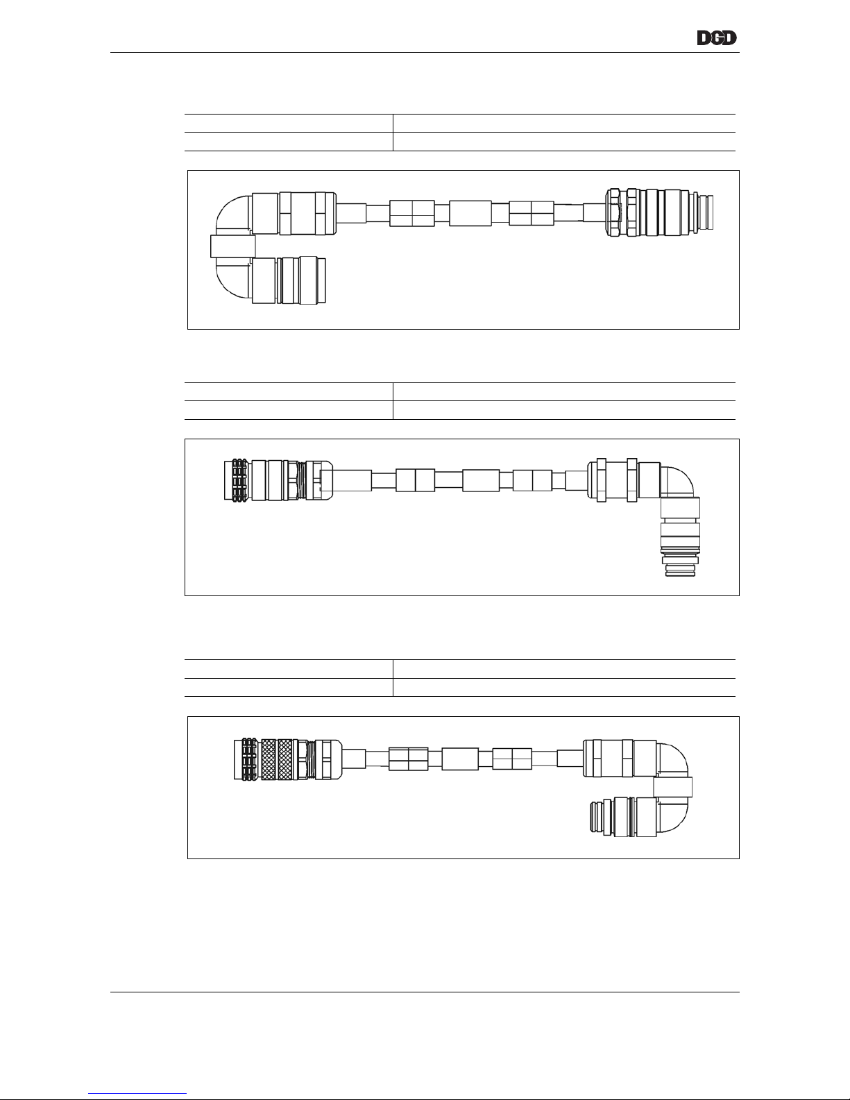
13.1.8 Jumper cable, type H
13.1.9 Jumper cable, type K
13.1.10 Jumper cable, type L
Use DGD-IS – DGD-IS
Order No. 961297--××× (…-××× = cable length in dm)
Use DGD-IS – DGD-IS
Order No. 961292-××× (…-××× = cable length in dm)
Use DGD-IS – DGD-IS
Order No. 961293--××× (…-××× = cable length in dm)
Page 57
17i_Kabel en.fm, 06.09.2011 P2077SB/EN 2011-09 57
Cable
13
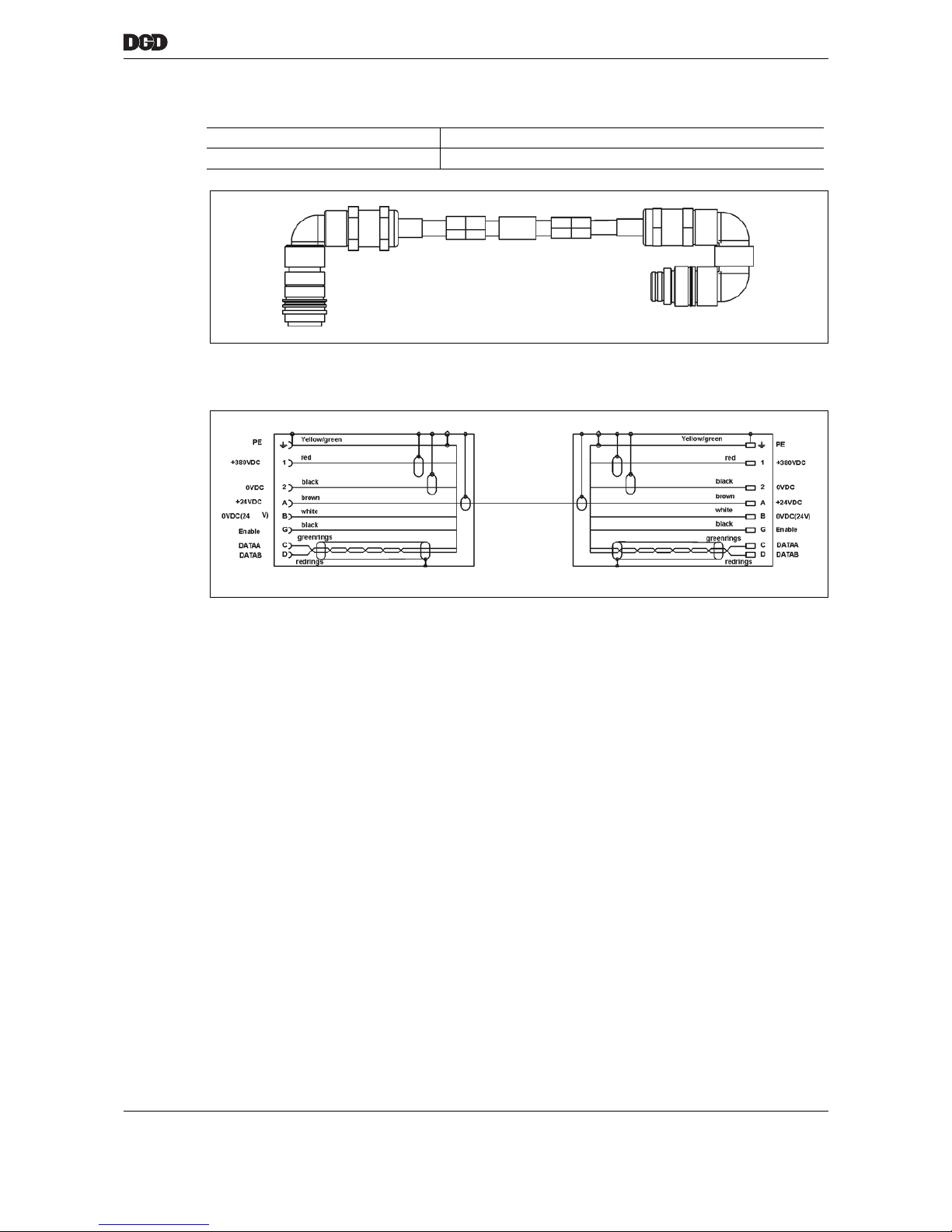
13.1.11 Jumper cable, type M
13.1.12 Wiring diagram
Use DGD-IS – DGD-IS
Order No. 961296--××× (…-××× = cable length in dm)
Page 58
58 P2077SB/EN 2011-09 17i_Kabel en.fm, 06.09.2011
Cable
13
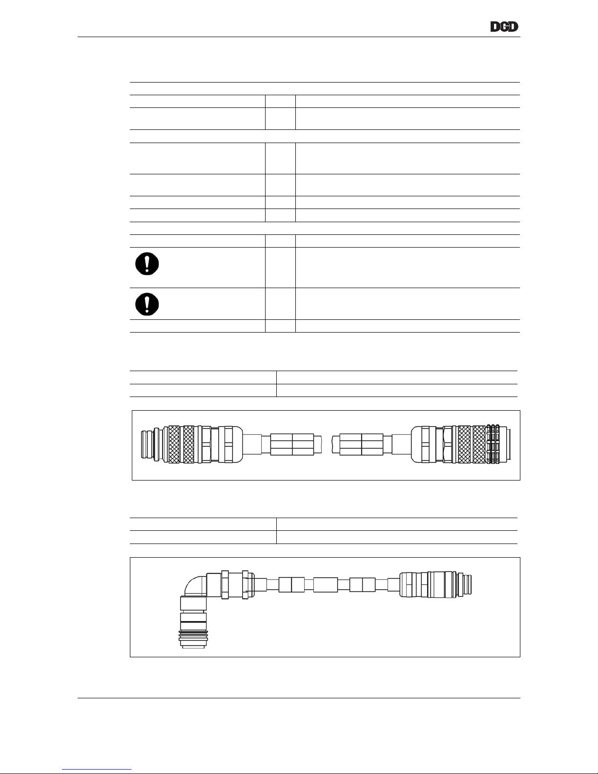
13.2 Super Highflex, suitable for robots
13.2.1 System cable, type A
13.2.2 Jumper cable, type F
Thermal properties
Ambient temperature °C -20…+90
Flammability Flame-retardant and self-extinguishing in accordance with
EN 50265-2-1, IEC 60332-1 and UL1581
Chemical properties of the coating
Coating material PUR, low-adhesion, resistant to hydrolysis and microbes,
UV-resistant, abrasion-resistant, tear-resistant, cut-resistant,
notch-resistant
Oil resistance Oil-resistant in accordance with DIN VDE 0472, part 803
ASTM oil 1 to 3 and HD 505.2.1
Resistance to hydrolysis In accordance with VDE 0283, part 10
Color Orange RAL 2003 matt
Mechanical properties
Diameter mm approx. 14
Bending radii:
Single bends
Multiple bends
mm
30 min.
60 mm min. flexing action
43 min alternate bending
Torsional length
(±180 ° around separate
central axis)
mm 500 min.
Max. acceleration m/s² 100
Use Intermediate plug position – DGD-IS
Order No. 961103-××× (…-××× = cable length in dm)
Use DGD-IS – DGD-IS
Order No. 961395-××× (…-××× = cable length in dm)
Page 59
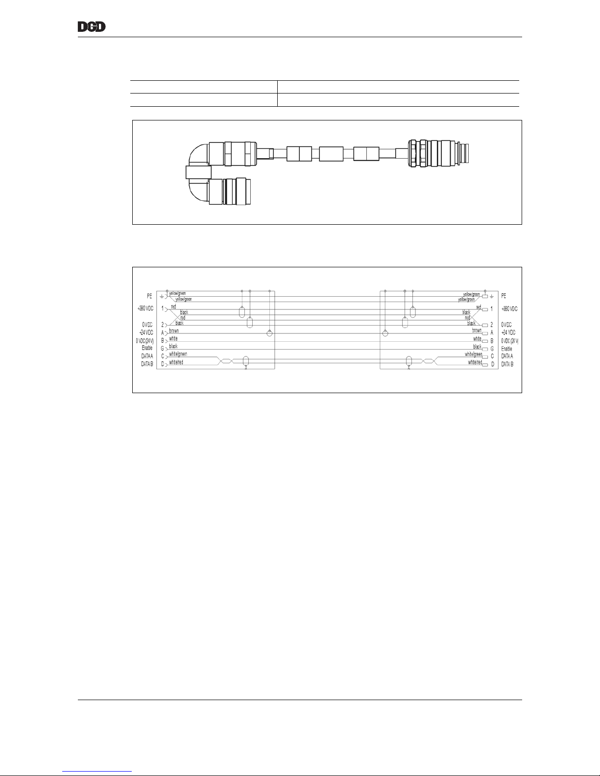
17i_Kabel en.fm, 06.09.2011 P2077SB/EN 2011-09 59
Cable
13
13.2.3 Jumper cable, type H
13.2.4 Wiring diagram
Use DGD-IS – DGD-IS
Order No. 961397--××× (…-××× = cable length in dm)
Page 60

60 P2077SB/EN 2011-09 17i_Kabel en.fm, 06.09.2011
Cable
13
Blank page
Page 61
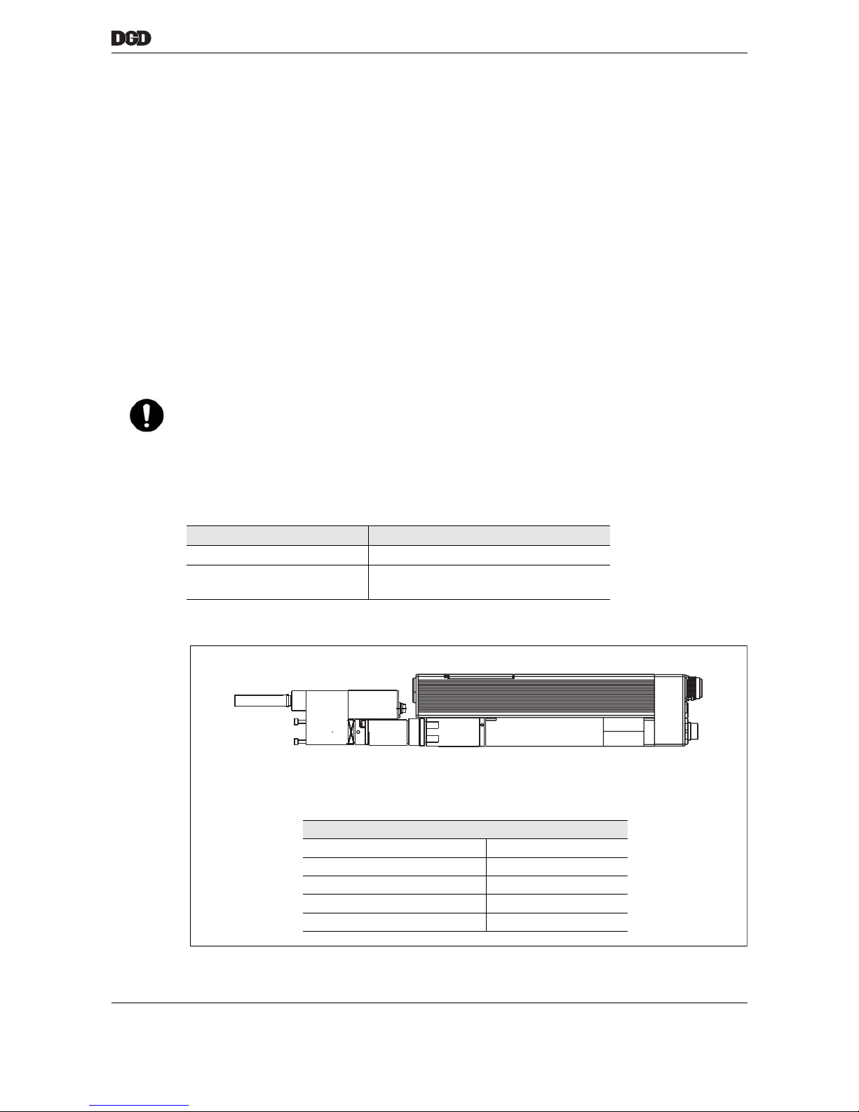
77k_Funktionsbeschreibung-en.fm, 06.09.2011 P2077SB/EN 2011-09 61
Function description
14
14 Function description
14.1 Torque measurement
The transducer is equipped with a telemetry system and therefore has no slip rings.
The transducer is either installed in the DGD-IS as a component or integrated in an offset attachment or
angle head attachment.
All components of the transducer (measuring shaft, antenna system, rotor electronics and stator electronics) belong together as one unit, i. e. individual assemblies cannot be replaced.
The rotor electronics are attached to the measuring shaft and are connected to the full strain gage bridge
and the rotor antenna system.
The stator electronics are located in the transducer housing. They incorporate the evaluation circuit, the stator antenna system and the 12-pin system connector.
The torque is measured directly at the attachment. Exception: the angle of the angle head attachment is
measured at the drive wheel. Torque measurement is made symmetrically for right and left-rotating torques
(tightening and loosening direction). The measured torque values are transferred from the transducer to the
measuring electronics via an amplified analog voltage (0...±5 V).
Calibration takes places in the rotor unit by means of a switched shunt resistor parallel to a strain gage measuring bridge section. The calibration signal has the following time characteristics:
Example of a DGD-IS standard
NOTE Always use measuring devices that are galvanically isolated from the protective earth (PE) ground connec-
tion for measuring the torque signals directly on the transducer (i.e. oscilloscope with isolation transformer).
When measuring, ensure that both 0 V reference connections of the transducer (0 V-torque/Pin D and
0 V-supply/Pin E) cannot be short-circuited.
Ignoring this may result in failures or measuring errors from potential equalization currents (between PE,
0 V TQ and 0 V supply) in the torque measurement circuit.
Input pulse duration (pin K) Output signal delay (pin C)
0...1.5 ms No output signal
1.5 ms...random Max. rise delay < 3 ms
Max. drop delay < 16 ms
77_DGD-IS_BTSE.eps
Offset version
1BTSE-1B012A-1VM3B Order no. 947627A5
Speed 1824 RPM
Torque max. 12 Nm
Kal Md 12 Nm, 5V DC
voltage 380 V DC
Page 62

62 P2077SB/EN 2011-09 77k_Funktionsbeschreibung-en.fm, 06.09.2011
Function description
14
Blank page
Page 63

77l_Fehlersuche-en.fm, 06.09.2011 P2077SB/EN 2011-09 63
Troubleshooting
15
15 Troubleshooting
The following displays will help you to troubleshoot
• Nutsetter control unit mPro400GC-M
• Supply module CPS3 (in PDB-CPS…)
• Tightening module TSE/TUSE (on DGD-IS) .
15.1 Acknowledgment of Errors
➔ Eliminate the malfunction and press the <Reset> button on the CPS3 or TSE/TUSE. The system is
again operational.
• The measuring board acknowledges faults pending in the TSE/TUSE each time a spindle starts.
• If the failure is brief (i.e. undervoltage), the TSE/TUSE becomes ready to operate automatically after the
next acknowledgment signal.
• All malfunctions in the DGD-IS (on in the CPS3) are archived in the mPro400GC-M. The error information is displayed here during troubleshooting.
• The error is permanent if the error mode cannot be acknowledged.
DANGER! High leakage current –
Fatal electric shock could occur!
➔ It is essential for the system cable or motor cable to be disconnected from the PDB-CPS… or
DGD-IS before making throughput, resistance and short circuit measurements.
NOTE • Always replace the CPS3 and the TSE/TUSE completely.
• Opening the CPS3 or TSE/TUSE will void the warranty. This does not include the service panel.
• Observe the conditions for operation, see 4 First Operation, page 13.
Page 64
64 P2077SB/EN 2011-09 77l_Fehlersuche-en.fm, 06.09.2011
Troubleshooting
15
15.2 DGD-IS
15.2.1 Transducer
When an operating failure occurs, the torque output is set to an output value of > 6.5 V and an
error bit is set in the operating data memory.
After an operation error, the transducer remains in the "operation error" state until one of the following
events occurs:
• the operating voltage of the transducer is disconnected
• the transducer receives a calibration signal via the CAL input (pin K).
• the error bit in the operating memory is reset via the RS422 RS422 interface.
Error
Description
Possible causes Measures and remedies
DGD-IS does not turn Motor defective
Gearing defective
Tightening module TSE/TUSE
defective
➔ Replace the DGD-IS
Cable defective
➔ Replace the cable
Loud noises Gearing wear
➔ Replace the DGD-IS
Error
Description
Possible causes Measures and remedies
Output signal is not linear
Measuring hub was overstretched
➔ Send the transducer to DGD
for repair / recalibration
Offset voltage is too high
Measuring hub was overstretched
No output signal Pre-amplifier is defective
Torque output is set to an
output value > 6.5 V
Error bit is set in the operating
data memory
CPU NOK
• internal transmission to D/A
converter fails
HF section NOK
• HF telemetry transmission
fails
• no measuring shaft (rotor)
present
• rotor electronics defective
• gap between rotor and stator
antenna too large
Supply voltage
• voltage under low supply
voltage limit
Page 65
77l_Fehlersuche-en.fm, 06.09.2011 P2077SB/EN 2011-09 65
Troubleshooting
15
15.3 Tightening module CPS3 in power distribution box PDB-CPS…
15.3.1 "Ready" LED
15.3.2 "EM stop" LED (emergency stop)
Error
Description
Possible causes Measures and remedies
"Ready" LED does not light up 24 V supply is unavailable ➔ Check the 26 V voltage at
"XS3" terminals 1 and 4
PDB-CPS… is disconnected from
the power supply
➔ Check the mains supply
24 V power adapter is disconnected from the power supply
➔ Check the fuse
Fuse in the CPS3 is
high-resistance
➔ Check the 26 V voltage at
"XS4" terminals 1 and 4
➔ Switch off the PDB-CPS…
and switch back on again
after a minute.
➔ Replace the CPS3
Error
Description
Possible causes Measures and remedies
"EM stop" lights up
CPS3
is in
Emergency stop status.
Intermediate power circuit (380
VDC) is deactivated.
No signals at the inputs Emergency stop "XS4", terminal 2 or
Control on "XS5", terminals 3
and 4.
➔ Check voltage 24 V at CPS3:
Plug connector "XS4"
Terminals 2 and 4;
Plug connector "XS5"
Terminals 3 and 4
➔ Check voltage 24 V at CP:
Plug connector "XS3"
Terminals 2 and 6;
Plug connector "XS2"
Terminals 5 and 6
Conclusion: the signals are not
generated by external controls.
Page 66
66 P2077SB/EN 2011-09 77l_Fehlersuche-en.fm, 06.09.2011
Troubleshooting
15
15.3.3 7-segment "Status" display
Encoded errors are displayed in a 7-segment display on the CPS3. The display alternates between the first
and second digit at brief intervals:
A period (.) in the display means NO error.
If several errors occur, the error with the highest priority is displayed, i.e. with the lowest number.
No information about faults and malfunctions that are detected by the CPS3 is transmitted to the
mPro400GC-M by ARCNET and displayed in the screen there.
Display Duration Pause
1st digit 0.5 s 0.2 s
2nd digit 0.5 s 1 s
1st digit 0.5 s 0.2 s etc.
Display
Error
Description
Possible causes Measures and
remedies
0-0 Error loading the inter-
mediate circuit capacitors
after switching on
Short circuit in the intermediate
circuit CPS3
➔ Replace the CPS3
• Cables
➔ Check the cables for short
circuiting between contacts
1 and 2 on the plug connectors and replace if necessary
• TSE/TUSE
➔ Replace the TSE/TUSE
• Main relay (Q4 or Q5 in PM)
does not switch
➔ Check the main relay,
replace if necessary
0-1 Faulty supply 3 x 270 VAC Phases missing ➔ Check phases
➔ Check mains supply
Safety relay PNOZ K2 in the
power module has triggered an
emergency stop
➔ Check the emergency stop
circuit
➔ Read the operating
instructions for the
PNOZ type X3P
Relay Q2 or Q3 has not
switched
➔ Check the relay,
replace if necessary
Supply voltage
• is too high,
U phase – phase > 300 VAC
• too low,
U phase – phase < 240 VAC
➔ Check the supply voltage
➔ Check mains supply
0-2 Excess current or short
circuit on braking chopper
Braking current > 200 A:
Short circuit in the braking
resistor
➔ Replace the CPS3
0-4 Braking chopper overload Braking resistor is overloaded.
The braking power is
> 100 W
eff.
Excessive number of DGD-IS.
➔ Reduce the number of
mPro400GC-M
DGD-IS is powered externally
➔ Check the mechanics
of the fastening station
Page 67
77l_Fehlersuche-en.fm, 06.09.2011 P2077SB/EN 2011-09 67
Troubleshooting
15
1-1 Excessive voltage
between artificial neutral
point of the power supply
and PE or the center of the
intermediate circuit
(approx. 190 VDC) and PE
Voltage > 100 V
Short circuit between
IC and PE:
➔ Check connection of inter-
mediate circuit voltage
+380 VDC and 0 VDC to
PE
• CPS3
➔ Check CPS3
– Replace
• System cable ➔ Replace the system cable
• TSE/TUSE
➔ Replace the TSE/TUSE
• Motor
➔ Replace the motor or
DGD-IS
1-2 Excessive current or
short circuit in the
intermediate circuit
Current > 250 A
Check the system cable
between the +380 VDC and 0 V
wires for short circuiting
• System cable short circuit
➔ Replace the cable
• Short circuit TSE/TUSE
➔ Replace the TSE/TUSE
1-3 Temperature of the
cooling element is too high
Temperature of CPS3,
cooling element is > 90 °C
Constant overload CPS3 Excessive number of DGD-IS.
➔ Reduce the number of
PDB-CPS…
Ambient temperature
PDB-CPS… > 40 °C
➔ Improve the ambient condi-
tions
PDB-CPS… is exposed to
other heat sources, i.e. sunlight
➔ Improve the ambient condi-
tions, attach covers if necessary
Heat dissipation from the
PDB-CPS… is inadequate due
to external conditions
➔ Ensure that air can circulate
through the cooling fins
1-4 I²t Error in intermediate
circuit
The intermediate circuit is overloaded.
Excessive number of DGD-IS.
➔ Reduce the number of
PDB-CPS…
1-6 The intermediate circuit
voltage is too high
Intermediate circuit voltage
480 VDC
May also occur momentarily
Braking chopper is defective ➔ Replace the CPS3
Excessive number of DGD-IS is
causing the braking chopper to
overload
➔ Reduce the number of
PDB-CPS…
Intermediate circuit capacitors
no longer have sufficient
capacity
Life span exceeded
➔ Replace CPS3
1-7 Intermediate circuit voltage
is too low
Intermediate circuit voltage
<250 VDC
Mains supply is not powerful
enough
Check the mains supply
➔ More powerful mains supply
required
Relay to the switch-on current
limiter is defective and permanently open
➔ Replace the CPS3
Excessive number of DGD-IS.
The voltage drops during
fastening
➔ Reduce the number of
PDB-CPS…
Display
Error
Description
Possible causes Measures and
remedies
Page 68
68 P2077SB/EN 2011-09 77l_Fehlersuche-en.fm, 06.09.2011
Troubleshooting
15
2-0 Temperature in CPS3 is too
high or too low
Temperature is outside of
the -40 °C to +85 °C range
Excessive number of DGD-IS.
Constant overload of the CPS3
➔ Reduce the number of
PDB-CPS…
Ambient temperature
PDB-CPS… > 40 °C
➔ Improve the ambient condi-
tions
PDB-CPS… is exposed to
other heat sources, i.e. sunlight
➔ Improve the ambient condi-
tions, attach covers if necessary
Heat dissipation from the
PDB-CPS… is inadequate due
to external conditions
➔ Ensure that air can circulate
through the cooling fins
Housing openings on the CPS3
are covered
➔ Clear the housing openings
2-1 Switch-on relay contact
does not open
Relay for switch-on current
limitation in the CPS3 is
stuck.
Detection only occurs when
switching on.
The relay contact is closed
during operation
Subsequent error – a different
fault destroyed the relay
➔ Replace the CPS3
Maximum number of switch-on
cycles exceeded
➔ Replace the CPS3
2-2 Intermediate circuit
(380 VDC) discharge not
possible
The intermediate circuit cannot be discharged
Subsequent error, a different
fault destroyed the relay
Main relay Q4 or Q5 in PM
does not open
➔ Replace the main relay Q4
or Q5
Braking chopper in the CPS3 is
defective
➔ Replace the CPS3
Braking resistor is highly resistive or burnt through
➔ Replace the CPS3
2-3 24V supply
24 V supply is not within the
range 21.5 V - 27.3 V
➔ Measure the voltage at
"XS3", terminals 1 and 6
24 V power adapter in
PDB-CPS… is defective
➔ Replace the power adapter
Power adapter T2 in
PDB-CPS… is overloaded
➔ Check the maximum load (8
A) on the CPS3
Voltage on power adapter in
PDB-CPS… is incorrect
➔ Set the voltage on the
power adapter to 26.0 V
Fuse (thermal) 24 V in the
CPS3 is highly resistive
➔ Switch off the PDB-CPS…
and switch back on again
after a minute.
➔ Check the maximum load –
replace the CPS3
Display
Error
Description
Possible causes Measures and
remedies
Page 69

77l_Fehlersuche-en.fm, 06.09.2011 P2077SB/EN 2011-09 69
Troubleshooting
15
2-5 5 V supply (internal)
Internal 5 V supply
is not within the
4.5 V – 5.5 V range
Internal voltage, external check not possible
Power adapter in the CPS3 is
defective
➔ Replace the CPS3
Power adapter in the CPS3 is
overloaded
➔ Replace the CPS3
2-7 Error in 15 V driver supply for
the braking chopper
The internal 15 V supply is
<12.5 V
Internal voltage can not be
checked externally
Power adapter in the CPS3 is
defective
➔ Replace the CPS3
Power adapter in the CPS3 is
overloaded
➔ Replace the CPS3
3-3 Initialization or
program error
Internal program error, no external actions possible
Error during program initializa-
tion
➔ Inform DGD service
➔ Switch the PDB-CPS… off
and on again
Communication error with a
service PC
➔ Reconnect PC to CPS3
Checksum error
➔ Inform DGD service
➔ Switch the PDB-CPS… off
and on again
Display
Error
Description
Possible causes Measures and
remedies
Page 70
70 P2077SB/EN 2011-09 77l_Fehlersuche-en.fm, 06.09.2011
Troubleshooting
15
15.4 Tightening module TSE/TUSE
15.4.1 "Ready" LED
15.5 Nutsetter control unit mPro400GC-M
15.5.1 Display on the Control Unit
All faults and malfunctions that the TSE/TUSE fastening electronics detect are transmitted to the
mPro400GC-M via ARCNET and then displayed on the screen.
If a malfunction develops in the TSE/TUSE or DGD-IS during tightening, the faults reported by the
TSE/TUSE in the rundown data table will appear:
IP, FLT, FMK, FHW, KAL1, KAL2, OFF1, OFF2, VAP, VLP, AN1F, AN2F.
In the bus map window system (see Programming Manual mPro400GC), all current errors are displayed in
plain text in the system information and listed in the following table.
Error
Description
Possible causes Measures and
remedies
"Ready" LED lights up red
Error in the TSE/TUSE For fault description on the
mPro400GC-M display,
see 15.5Nutsetter control unit
mPro400GC-M
"Ready" LED does not light
up
24 V supply is unavailable, the
TSE/TUSE is not connected to
the power supply
➔ Measure the voltage
24 – 26 V at "XS1B",
sockets A and B
➔ Check the error display for
the PDB-CPS… on the
CPS3.
➔ If error present, go to 15.3
Tightening module CPS3 in
power distribution box PDBCPS…, page 65
➔ Replace the system cable
TSE/TUSE is defective
➔ Replace the TSE/TUSE
Page 71
77l_Fehlersuche-en.fm, 06.09.2011 P2077SB/EN 2011-09 71
Troubleshooting
15
Error
Description
Possible causes Measures and
remedies
Servo:
IP monitoring: NOK
(also displayed in the rundown
data table)
Overload
If a current higher than the maximum permissible current is
required for fastening, the servo
amplifier switches off automatically.
Error in
motor position tracing,
i.e. resolver cable
Check the resolver wires in the
nutsetter cable
➔ Replace the nutsetter cable
and check the resolver wires
in the nutsetter cable for
breaks
➔ Replace the DGD-IS or motor
Error in the motor circuit, i.e.
motor does not attain the
required torque
➔ Check motor for short circuit
to PE and phase resistances:
1BT… approx. 11 ,
2BT approx. 2 ,
3/4BT… approx. 0.6 W.
➔ Replace motor
Incorrect programming
➔ Check programming in
mPro400GC-M
– Spindle constants
– Calibration values
– Fastening process
(sequence)
– Parameter set
– Targets
Servo:
Intermediate circuit voltage:
too high
The voltage in the
intermediate power circuit is
> 440 VDC
Constant error See CPS3 troubleshooting –
no error on CPS3
➔ Replace the TSE/TUSE
The error is triggered during
braking, i. e. when the DGD-IS
stops
See CPS3 troubleshooting –
no error on CPS3
➔ Replace the TSE/TUSE
Sporadically, the voltage is temporarily too high
See CPS3 troubleshooting –
no error on CPS3
➔ Replace the TSE/TUSE
Servo:
Intermediate circuit voltage:
too low
The voltage in the intermediate
power circuit is < 190 VDC
Constant error See CPS3 troubleshooting –
no error on CPS3
➔ Check the system cable for
interruptions
➔ Replace the system cable
System cable OK
➔ Replace the TSE/TUSE
During fastening, error is triggered during the fastening process
See CPS3 troubleshooting –
no error on CPS3
➔ Replace the TSE/TUSE
Sporadically, the voltage is temporarily too low
See CPS3 troubleshooting –
no error on CPS3
➔ Check the mains power sup-
ply for voltage drops
Page 72
72 P2077SB/EN 2011-09 77l_Fehlersuche-en.fm, 06.09.2011
Troubleshooting
15
Servo:
Temperature output section:
too high
The temperature in the
TSE/TUSE output section is
> 80 °C
The temperature sensor in the
TSE/TUSE measures a temperature > 80 °C
Check temperature if > 80 °C
➔ ensure adequate ventilation
of the DGD-IS
DGD-IS is ventilated sufficiently
➔ Replace the TSE/TUSE
Servo:
Driver supply output section:
NOK
The power adapter for the internal supply to the output section is
overloaded or defective.
Internal error
➔ Replace the TSE/TUSE
Servo:
Offset of current measurement:
NOK
The zero point of the integrated
motor current measurement has
moved
Internal error
➔ Replace the TSE/TUSE
Servo:
SSIO communication: NOK
The communication interface
between the servo amplifier and
the measuring board is faulty
Internal error
➔ Replace the TSE/TUSE
Servo:
Node guarding: NOK
The servo amplifier monitors the
function of the measuring board
(watchdog).
Sporadic
malfunction of the measuring
board
Internal error
➔ Replace the TSE/TUSE
Servo:
Flash: NOK
The flash memory in the
servo amplifier indicates an error
Internal error
➔ Replace the TSE/TUSE
Servo:
Program: NOK
Error in the
program execution for the servo
amplifier
Internal error
➔ Replace the TSE/TUSE
➔ Inform CPT Service
Motor:
Motor cable: NOK
Motor wire in DGD-IS is
interrupted
Cable break in
TSE/TUSE motor wires
➔ Check the motor wires for
breaks and short circuits
Motor phases interrupted
➔ Check motor for short circuit
to ground and phase resistances:
1BT… approx. 11 ,
2BT approx. 2 ,
3/4BT… approx. 0.6 W.
➔ Replace motor
Test current for cable monitoring
is misdirected
➔ Replace motor
Internal error
➔ Replace the TSE/TUSE
Error
Description
Possible causes Measures and
remedies
Page 73
77l_Fehlersuche-en.fm, 06.09.2011 P2077SB/EN 2011-09 73
Troubleshooting
15
Motor:
Short circuit surveillance: NOK
Motor short circuit monitoring
There is a short circuit in the
motor circuit on the DGD-IS
in the motor Check the motor for short circuits
(for phase impedances, see
above)
➔ Replace motor
In the TSE/TUSE Internal error
➔ Replace the TSE/TUSE
Motor:
Temperature: NOK
The motor temperature is > 90 °C
The temperature sensor in the
motor measures a temperature
> 90 °C
Check the motor temperature,
if > 90 °C
➔ ensure adequate ventilation
of the motor
Measuring cable in the motor is
interrupted
Check the thermosensor for
breaks. The resistance should be
approx. 1 K at 20 °C
➔ Replace motor
Measuring current is misdirected Check the wires in the DGD-IS
for breaks and short circuits
➔ Replace motor
Measuring current is not measured
Internal error,
➔ Replace the TSE/TUSE
Motor is not connected
➔ Connect the motor
Motor:
I
2
t monitoring: NOK
The I²t monitor has measured
excessive power on the DGD-IS
Motor power required is too high Check the motor temperature,
if > 80 °C
➔ Shorten the fastening time by
increasing the speed
DGD-IS is defective (i.e. gearing, bearings)
Check the ease of movement of
the gearing and motor on the
DGD-IS
➔ Replace the DGD-IS or motor
Motor:
Resolver: NOK
No resolver signals measured
Signals are not present Check whether the motor is con-
nected
➔ Connect the motor
Signal interruption Check the resolver wires in the
DGD-IS
➔ Replace motor
Short circuit of signals Check the resolver wires in the
DGD-IS for short circuits
➔ Replace motor
Supply to the resolver is defective
Internal defect
➔ Replace the TSE/TUSE
Measurement card:
Task monitoring: NOK
Error at the program execution
end of the measuring board
Internal error
➔ Replace the TSE/TUSE
➔ Inform DGD service
Measurement card:
RAM:
Insufficient RAM available in the
measuring board
Internal error
➔ Replace the TSE/TUSE
➔ Inform DGD service
Error
Description
Possible causes Measures and
remedies
Page 74
74 P2077SB/EN 2011-09 77l_Fehlersuche-en.fm, 06.09.2011
Troubleshooting
15
Measurement card:
Sampling clock from servo:
NOK
The system clock from the servo
amplifier is missing
Internal error
➔ Replace the TSE/TUSE
Measurement card:
Servo type correct: NOK
The selected servo amplifier type
is incorrect
Error in programming
➔ Check the system program-
ming
Self-identification of transducer is
not OK
Check the transducer
➔ Replace the transducer
Internal error
➔ Replace the TSE/TUSE
Measurement card:
Servo par. matching servo:
NOK
The parameter set selected from
the measuring board is not
present in the TSE/TUSE.
Error in programming
➔ Check the system program-
ming
Self-identification of transducer is
not OK
Check the transducer
➔ Replace the transducer
Internal error
➔ Replace the TSE/TUSE
Measurement card:
ARCNET communication:
Dup-ID
The same ARCNET addresses
are preset
Several TSE/TUSE are preset to
the same ARCNET address
Check the preset ARCNET
addresses
➔ Set different addresses
Measurement card:
ARCNET communication:
Recon
The ARCNET is temporarily
disrupted
ARCNET terminator missing
➔ Plug in the ARCNET termina-
tor
No power supply to the ARCNET
terminator
➔ Switch on the power supply
for the last device
Error in cabling
➔ Plug in all cables and lock
Error in potential equalization
➔ Connect potential equaliza-
tion cable
Internal error
➔ Replace the TSE/TUSE
Measurement card:
Initialization: NOK
Initialization error in measuring
board
Internal error
➔ Replace the TSE/TUSE
➔ Inform DGD service
Measurement card:
Flash image: NOK
Flash image in the measuring
board is not OK
The incorrect program has been
transmitted by mPro400GC-M
➔ Check the program version
The program transfer was
interrupted
➔ Repeat the program transfer
Internal error
➔ Replace the TSE/TUSE
Measurement card:
Voltage +3.3 V (…): NOK
The +3.3 V supply to the measuring board is outside the limits of
+3.24 V... +3.53 V
The power adapter for the internal supply to the measuring
board is overloaded or defective.
Internal error
➔ Replace the TSE/TUSE
Error
Description
Possible causes Measures and
remedies
Page 75
77l_Fehlersuche-en.fm, 06.09.2011 P2077SB/EN 2011-09 75
Troubleshooting
15
Measurement card:
Voltage +12 V (…): NOK
The +12 V supply to the measuring board and the transducer is
outside the limits of
+11.4 V... +12.6 V
+12 V short circuiting in the
KMAG/KMAW or DGD-IS
Check the mPro400GC-M in the
Diagnosis>Voltages menu. If
values are outside permissible
limits, check the KMAG/KMAW
cables
(transducer – TSE/TUSE), especially the +12 V and 0 V wires.
➔ Replace the cable
➔ Replace the transducer or
DGD-IS
Internal power adapter defective ➔ Replace the TSE/TUSE
Measurement card:
Voltage +24 V (…): NOK
The +24 V supply of the TSE/
TUSE is outside the limits of
+20.4 V…+27.6 V
Supply is overloaded Check the mPro400GC-M in the
Diagnosis>Voltages menu. If
values are outside permissible
limits
➔ Check the load
Voltage on power adapter in
PDB-CPS… is incorrect
➔ Set the power adapter to
26.0 V
Measurement card:
Temperature (…): NOK
The temperature on the measuring board is > 80 °C
The temperature sensor in the
TSE/TUSE measures a temperature > 80 °C
➔ ensure adequate ventilation
of the DGD-IS
Internal error DGD-IS is ventilated sufficiently
➔ Replace the DGD-IS
Transducer:
…Connected: NOK
The signals from the transducer
are not OK
The connection to the transducer is
– interrupted
Check the KMAG/KMAW cable
(transducer – TSE/TUSE) for
breaks
➔ Replace the cable
➔ Replace the transducer
– short-circuited Check the KMAG/KMAW
cable for short circuits
➔ Replace the cable
➔ Replace the transducer
– unavailable
➔ Connect the transducer
➔ Replace the cable
Internal error
➔ Replace the TSE/TUSE
Transducer:
Calibration voltage: NOK
The calibration voltage is outside
the permissible range of
+4.85 V...+5.15 V
The calibration signal is interrupted
➔ Check the KMAG/KMAW
cable for breaks, especially
the calibration signal wire
The calibration signal is short circuiting with another signal
Check the KMAG/KMAW cable
(transducer – TSE/TUSE) for
short circuits
➔ Replace the cable
Error in the transducer
➔ Replace the transducer
Internal error
➔ Replace the TSE/TUSE
Error
Description
Possible causes Measures and
remedies
Page 76
76 P2077SB/EN 2011-09 77l_Fehlersuche-en.fm, 06.09.2011
Troubleshooting
15
Transducer:
Offset value: NOK
The zero-point voltage is outside
the permissible range of
-200 mV...+200 mV
The torque signal is interrupted Check the mPro400GC-M in test
mode Diagnosis>Voltages.
If values are outside permissible
limits:
Check the KMAG/KMAW cable
(transducer – TSE/TUSE) for
breaks
➔ Replace the cable
The torque signal is short circuiting with another signal
Check the KMAG/KMAW cable
(transducer – TSE/TUSE) for
short circuits
➔ Replace the cable
Error in the transducer
➔ Replace the transducer
Internal error
➔ Replace the TSE/TUSE
Transducer:
CRC of service memory: NOK
Could not read in the data for
self-identification correctly
The data cables are
– interrupted
Check the KMAG/KMAW cable
(transducer – TSE/TUSE) for
breaks, especially the signal
wires for data transfer (RS422)
➔ Replace the cable
– short circuiting with another
signal
Check the KMAG/KMAW cable
(transducer – TSE/TUSE) for
short circuits
➔ Replace the cable
Error in the transducer
➔ Replace the transducer
Communication was disrupted
when the transducer was
plugged in
➔ Unplug and plug in again
Transducer:
Tool identification: NOK
The data for self-identification of
the transducer are not verified by
the mPro400GC-M
Data communication failed Copy data to mPro400GC-M,
see Programming Manual
mPro400GC
➔ Acknowledge the TSE/TUSE
with <Reset>
Data communication not
completed yet
Copy data to mPro400GC-M,
see Programming Manual
mPro400GC
➔ Acknowledge the TSE/TUSE
with <Reset>
Error
Description
Possible causes Measures and
remedies
Page 77
77m_Wartung_Entsorgung_bedingt-en.fm, 06.09.2011 P2077SB/EN 2011-09 77
Maintenance / Service
16
16 Maintenance / Service
Only trained personnel are permitted to perform maintenance. Please refer to the Service Manual DGD-IS.
Regular maintenance reduces operating faults, repair costs and downtime. Implement a safety-related
maintenance program that takes the local regulations for repair and maintenance for all operating phases of
the tool into account.
17 Disposal
DANGER! High leakage current –
Fatal electric shock could occur!
➔ Always disconnect the power supply before performing maintenance work on the DGD-IS and the
mPro400GC-M.
➔ Always disconnect the system cable, motor or motor cable from the
mPro400GC-M or DGD-IS before making throughput, resistance and short circuit measurements.
➔ Do not attempt to repair possible faults on the fastening system by yourself if you do not have the
required knowledge! Please consult your local service agent or the responsible Sales & Service Center
(see backside).
➔ Establish a grounding connection (PE) to the nutsetter control unit mPro400GC-M before taking into
operation!
WARNING!
High temperature –
the motor on the DGD-IS may heat up and cause burns during removal.
(max. engine temperature 90 °C). Wear gloves.
CAUTION!
Injuries and environmental damage from improper disposal.
Components of the DGD-IS pose risks to the health and the environment.
➔ The DGD-IS contains components that can be reused as well as components that require special
disposal. Separate the components and dispose of them by segregating them clearly.
➔ Catch auxiliary materials (oils, greases) when drained and dispose of them properly.
➔ Separate the components of the packing and dispose of them by segregating them clearly.
➔ Follow the locally applicable regulations.
Observe generally valid disposal guidelines such as, in Germany, the Electrical and Electronic Equipment
Act (ElektroG):
➔ Hand in the DGD-IS at your company collection point or return to Sales & Service Center (see back-
side).
Page 78

Apex Tool Group GmbH & Co. OHG
Industriestraße 1
73463 Westhausen
Germany
Phone: +49-7363-81-0
Fax: +49-7363-81-222
www.apexpowertools.eu
Sales & Service Centers
Note: All locations may not service all products. Please contact the nearest Sales & Service Center for the
appropriate facility to handle your service requirements.
Dallas, TX
Apex Tool Group
Sales & Service Center
1470 Post & Paddock
Grand Prairie, TX 75050
USA
Phone: +1-972-641-9563
Fax: +1-972-641-9674
Detroit, MI
Apex Tool Group
Sales & Service Center
2630 Superior Court
Auburn Hills, MI 48326
USA
Phone:+1-248-391-3700
Fax: +1-248-391-7824
Houston, TX
Apex Tool Group
Sales & Service Center
6550 West Sam Houston
Parkway North, Suite 200
Houston, TX 77041
USA
Phone: +1-713-849-2364
Fax: +1-713-849-2047
Lexington, SC
Apex Tool Group
670 Industrial Drive
Lexington, SC 29072
USA
Phone: +1-800-845-5629
Phone: +1-803-359-1200
Fax: +1-803-358-7681
Los Angeles, CA
Apex Tool Group
Sales & Service Center
15503 Blackburn Avenue
Norwalk, CA 90650
USA
Phone: +1-562-926-0810
Fax: +1-562-802-1718
Seattle, WA
Apex Tool Group
Sales & Service Center
2865 152nd Avenue N.E.
Redmond, WA 98052
USA
Phone: +1-425-497-0476
Fax: +1-425-497-0496
York, PA
Apex Tool Group
Sales & Service Center
3990 East Market Street
York, PA 17402
USA
Phone: +1-717-755-2933
Fax: +1-717-757-5063
Canada
Apex Tool Group
Sales & Service Center
5925 McLaughlin Road
Mississauga, Ont. L5R 1B8
Canada
Phone: +1-905-501-4785
Fax: +1-905-501-4786
Germany
Apex Tool Group
GmbH & Co. OHG
Industriestraße 1
73463 Westhausen
Germany
Phone: +49-73 63-81-0
Fax: +49-73 63/ 81-222
England
Apex Tool Group, LLC
Pit Hill
Piccadilly
Tamworth
Staffordshire
B78 2ER
U.K.
Phone: +44-191 4197700
Fax: +44-182 7874128
France
Apex Tool Group SAS
Zone Industrielle
BP 28
25 Avenue Maurice Chevalier
77831 Ozoir-la-Ferrière Cedex
France
Phone: +33-1-64432200
Fax: +33-1-64401717
China
Apex Power Tools Trading (Shanghai) Co., Ltd
A company of
Apex Tool Group, LLC
A8, No.38, Dongsheng
Road, Shanghai,
China 201201
Phone: +86-21-60880320
Fax: +86-21-60880298
Mexico
Cooper Tools
de México S.A. de C.V.
a company of
Apex Tool Group, LLC
Vialidad El Pueblito #103
Parque Industrial Querétaro
Querétaro, QRO 76220
Phone: +52 (442) 211-3800
Fax: +52 (442) 103-0443
Brazil
Cooper Tools Industrial Ltda.
a company of
Apex Tool Group, LLC
Av. Liberdade, 4055
Zona Industrial - Iporanga
18087-170 Sorocaba, SP Brazil
Phone: +55-15-3238-3929
Fax: +55-15-3228-3260
 Loading...