


Programming Manual
PL12EN-TVP100
03/07/2013
TVP-100 Series
Pneumatic Torque Verier - Version 1.0
TVP-110-15
For additional product information visit our website at http://www.apextoolgroup.com
TVP-110-30


Cleco
®
PL12EN-TVP100
03/07/2013
Pneumatic Torque Verifier TVP-100 Series
Disclaimer:
The information and data in this document has been prepared to the best of our ability.
Nonetheless, differences between the information and the actual product cannot be excluded
with absolute certainty. Apex Tool Group does not assume any liability for consequential errors
and damages. We likewise do not assume liability for damages resulting from defective circuitry
inside the devices supplied. Apex Tool Group reserves the right, to amend, supplement or
improve this document or the product without serving prior notice.
Without the express approval of Apex Tool Group this document must not be reproduced in
its entirety or in part by any means; it must not be converted to any type of natural or machine
readable language or be saved on data storage media of electronic, mechanic, optical or other
type.
Page 3

PL12EN-TVP100
03/07/2013
Cleco
®
Pneumatic Torque Verifier TVP-100 Series
Contents
1 Getting Started ..................................................................................................................6
1.1 Safe Work Practices Symbol .............................................................................................. 6
1.2 Transportation .....................................................................................................................6
1.2.1 Unpacking ...........................................................................................................................6
1.2.2 Checking Your Unit .............................................................................................................6
1.3 Software .............................................................................................................................6
1.4 Installing The Unit ............................................................................................................... 6
1.4.1 General ............................................................................................................................... 6
1.4.2 Mounting ............................................................................................................................. 7
1.4.3 Location Considerations ..................................................................................................... 7
1.4.4 Source Power ..................................................................................................................... 7
1.5 Connecting Peripherals ......................................................................................................7
1.6 Maintenance, Troubleshooting and Repair .........................................................................7
2 Operation - Quick Start Guide ......................................................................................... 8
2.1 Powering Up The Unit ........................................................................................................8
2.2 The Ship’s Wheel ...............................................................................................................8
2.3 Selecting Tool Type .............................................................................................................8
2.4 Calibration (AutoCal) ..........................................................................................................9
2.5 Setting Fasteners Per Batch .............................................................................................10
2.6 Running The Unit ..............................................................................................................10
3 Controller Specications ............................................................................................... 11
3.1 IP Protection Class ........................................................................................................... 11
3.2 Understanding The Keypad .............................................................................................. 11
3.3 Specications ...................................................................................................................12
3.3.1 Enclosure ..........................................................................................................................12
3.3.2 Display .............................................................................................................................. 12
3.3.3 Indicators .......................................................................................................................... 13
3.3.4 AC Input Power ................................................................................................................13
3.3.5 TVP-110-15 (115VAC) Input/Output Connectors .............................................................. 13
3.3.6 TVP-110-30 (230VAC) Input/Output Connectors ..............................................................15
3.4 Decommissioning of Unit .................................................................................................. 16
4 Programming ..................................................................................................................17
4.1 Run Screen .......................................................................................................................17
4.2 Navigation Menu ...............................................................................................................18
4.3 AutoCal ............................................................................................................................. 18
4.4 Viewing A Run ..................................................................................................................19
4.5 Statistics ...........................................................................................................................20
4.6 Options .............................................................................................................................20
4.6.1 Relay Options ................................................................................................................... 21
4.6.2 Beeper Options .................................................................................................................21
4.6.3 Application Select Input .................................................................................................... 22
4.6.4 Time and Date .................................................................................................................. 23
4.6.5 Tool Type ..........................................................................................................................24
4.6.6 Adjusting The Display ....................................................................................................... 24
4.7 Selecting Application ........................................................................................................25
4.8 Application Builder ............................................................................................................ 25
4.9 Sequencing .......................................................................................................................27
4.10 Administration ................................................................................................................... 27
4.11 I/O Schematic ................................................................................................................... 28
Page 4

Cleco
®
PL12EN-TVP100
Pneumatic Torque Verifier TVP-100 Series
Contents
A Appendix .........................................................................................................................29
A.1 Pneumatic Curves (Pulse Tool) ........................................................................................29
A.2 Pnuematic Curves (Direct Drive Tool) .............................................................................. 32
A.3 Box Dimensions ................................................................................................................35
A.4 Tool and Box Diagrams .................................................................................................... 35
B Appendix .........................................................................................................................36
B.1 Dip-Switch Settings ..........................................................................................................36
B.2 Test Modes .......................................................................................................................36
03/07/2013
Page 5

PL12EN-TVP100
03/07/2013
Cleco
®
Pneumatic Torque Verifier TVP-100 Series
1 Getting Started
1.1 Safe Work Practices Symbol
This“Warning”symbolidentiesallnotesonsafeworkpracticesinthisoperating
instruction, alerting to hazards for life and health of people. Please observe these
notes and proceed with special care in the cases described. Pass all safety
instructions on to other operators. In addition to the safety instructions in this operating
instruction, the general local safety and accident prevention rules must be observed.
The signal word “Caution” identies all portions of this operating instruction
meriting special attention to ensure that guidelines, rules, hints and the correct
work procedures are observed; and, to prevent damage to and destruction of
the machine and/or parts.
1.2 Transportation
This unit does not require any special transportation instructions.
1.2.1 Unpacking
This unit does not require any special unpacking instructions.
1.2.2 Checking Your Unit
Take the time to ensure that you have the required peripheral equipment and cables
necessary to setup and run your unit. If you do not have all the necessary items, please
contact your distributor.
1.3 Software
Your unit has been pre-loaded with its software and requires no additional software to
start monitoring your fastening process. If you are trying to interface this unit to an external computer, additional software may be required. Please contact your distributor with
inquires about interface software.
1.4 Installation Of The Unit
1.4.1 General
It is mandatory that national, state, and local safety and wiring standards
be followed during installation. These standards would take precedence
over any information presented in this section.
To avoid the hazard of electrical shock or burn, the following instructions must be
adhered to. Failure to follow these instructions may also cause damage to your
unit and void existing warranties.
Do not energize the unit until all connections have been properly made.•
Equipment must be properly grounded before applying power. Units energized •
by cord and plug must be connected to an approved and properly grounded
receptacle.
Ensure the power switch is in the “off” position before applying power.•
Page 6

Pneumatic Torque Verifier TVP-100 Series
1.4.2 Mounting
Each TVP-100 Series unit is intended to be used as a single tool process monitor in a
work station or work area. This unit may be wall mounted, table mounted, beam mounted,
suspended overhead, pedestal mounted, or used without mounting. Tabs have been
provided on the base of this unit to ease this mounting process. Please take care in
choosing a stable location for the unit to avoid the possibility of damage to the unit and/
or operator injury through hitting, falling, vibration or inconvenient mounting. All cables
attached to the unit should be located and secured in a manner to avoid potential operator
and passer-by injury. As with all electric equipment, the unit will produce some heat and
should be located so that ambient air can freely circulate around the box.
1.4.3 Location Consideration
Your unit should be located to allow access to the front panel and connectors. The unit
should be installed for unrestricted and comfortable viewing of the LCD and LED’s by
the operator. The LCD menu screen, key pad and side panel connectors must be readily
accessible for the setup. Depending on the peripheral equipment purchased, the unit may
be remotely mounted but should still be accessible.
Cleco
®
PL12EN-TVP100
03/07/2013
1.4.4 Source Power
This unit is capable of being run off of 115 or 230 VAC (both 50 and 60 Hz).
Before powering up the unit for the rst time, take care to notice which
voltage the unit is set up to accept. Damage to the unit may occur if the
voltage selection does not match the power that is supplied,
The TVP-100 is fused at 1 Amp for 115 V.•
The TVP-100 is fused at 5 Amp for 230 V.•
1.5 Connecting Peripherals
A pressure transducer was supplied with your unit. This transducer needs to be properly
connected to the tool that is being monitored and also to this unit. Other inputs and
outputs are available for communicating with devices such as PLCs and PCs. Make sure
these devices are connected to the proper ports before powering up the unit. Damage
can occur to the units if these inputs and outputs are used incorrectly.
To avoid the hazard of electrical shock or burn the following instructions
must be adhered to. Failure to follow these instructions may also cause
damage to your unit and void existing warranties.
Ensure the power switch is in the “off” position and that the box cover is properly •
secured before supplying power to the unit.
Ensure equipment has been properly grounded before applying power.•
1.6 Maintenance, Troubleshooting and Repair
Periodic maintenance of this equipment is not required. Repair is restricted to programming
issues.
Page 7

PL12EN-TVP100
03/07/2013
Pneumatic Torque Verifier TVP-100 Series
2 Operation - Quick Start Guide
2.1 Powering Up The Unit
This quick-start guide assumes that the unit is set up properly, that the unit can be
powered up, and that the transducer is properly attached to the tool being monitored and
this unit. If you need more guidance in any of these areas, please refer to the in depth
directions found later in this manual.
2.2 The Ship’s Wheel
When the unit powers up, a splash screen will be displayed momentarily followed by the
main run screen. In order to set up any given tool, press the “ship’s wheel” key and go to
the navigation menu.
Torque Verier
TVP-110-15
F1.01 B2.96
Cleco
RUN SCREEN
Cycle Count:
ACCEPT
BATCH
ACCEPT
REJECT
SUSPEND UNLOCK
Cycle Accept
Batch Total:
RESET
BATCH
®
APPLICATION
of:
Run Screen
AutoCal
psi
View Run
Statistics
Options
Select Application
Application Builder
Sequencing
Administration
I/O Schematic
2.3 Selecting Tool Type
With the navigation menu showing, use the arrow keys to highlight the “Options” icon and
then use the “Enter” key to select “Options”. You may be prompted to enter a password.
If so, enter it using the numeric keypad, the default is “0 1 0 4”. At this point, the Options
Screenwillappear.FromtheOptionsScreenselectthefthoption(ToolType)bypressing
the 5 key. The Tool Type screen will appear at this point. Threre are two options for Cleco
Pulse tools. Option 1 (Pulse Pneumatic) is typically for larger pulse tools, about 20Nm
and larger. Option 3 (7/11 PTH) is typically for smaller pulse tools. All other pneumatic
tools, Option 2 (Direct-drive Pneumatic) should be selected.
Pressing the “Ship’s Wheel” will return the user to the navigation menu.
Run Screen
AutoCal
View Run
Statistics
Options
Select Application
Application Builder
Sequencing
Administration
I/O Schematic
5. Tool Type
Options
TOOL TYPE
1. Pulse Pneumatic
2. Direct-drive Pneumatic
3. 7/11 PTH
OPTIONS MENU
1. Relays
2. Beeper
3. Parameter Switch Type
4. Time / Date
5. Tool Type
6. Adjust Display
Save EXIT
5
Save EXITDownUp
Page 8

Pneumatic Torque Verifier TVP-100 Series
2.4 Calibration (AutoCal)
Before a tool can be monitored properly, the current application must be set up to monitor
that tool. The AutoCal option will do this for you automatically. In order to access the AutoCal
routine, press the “Ship’s Wheel” button and go to the navigation screen. From the navigation
screen, use the arrow keys to highlight the AutoCal option and then press enter.
Cleco
®
PL12EN-TVP100
03/07/2013
Run Screen
AutoCal
View Run
Statistics
Options
Select Application
Application Builder
Sequencing
Administration
I/O Schematic
You may be prompted to enter a password. If so, enter it using the numeric keypad. The
default password is “0 1 0 4”.
Please enter your password
to contonue.
0 1 0 4
TherstscreenassociatedwiththeAutoCalprocesswillinformtheuserthatthetoolmust
be off and also that they should press the “Next” key. This screen also reminds the user
which application set is active. The calibration will only effect that application. At this
point, make sure the transducer is connected to both the tool and the box and also that
the tool is not running. Then press the “Next” softkey.
AUTOCAL
Tool must be OFF.
Press NEXT to continue
the AutoCalibration
for Application A.
NEXT
Select
EXIT
Application
NEXT
The second AutoCal screen will appear next. This screen will prompt the user to run a
typical fastener and then to press the “Next” softkey. After these steps are completed, the
result of the calibration will appear on the screen.
AUTOCAL
The Qualier will use the
last fastening cycle to
AutoCal.
OR
Run a sample fastener now.
Press NEXT to continue.
EXIT
NEXT
Run Typical
Fastener
NEXT
AUTOCAL
Auto Calibration was successful.
Press NEXT to continue.
EXIT
NEXT
If the calibration was not successful, you may need to check the tool connection to the
unit. On the “Run Screen” there is a portion of the window that shows the active pressure
within the tool. Check this pressure as the tool is running to see if a change is occurring.
Press the “Ship’s Wheel” to return to the navigation menu.
Page 9

PL12EN-TVP100
03/07/2013
Pneumatic Torque Verifier TVP-100 Series
2.4 Calibration (AutoCal) - continued
With Pulse Tools, an oversized air regulator and air hose can cause pressure waves at the
signal port after the tool has shut off. This can hinder a successful AutoCal.
2.5 Setting Fasteners Per Batch
Thenalstepinsettingupanygivenapplicationistoprogramthenumberoffasteners
which will be in each batch or group. For example, if this unit is to monitor the fastening
Run Screen
AutoCal
View Run
Statistics
Options
ofvelugnutsintoacar’swheel,thebatchmightbesettove.
In order to set the batch, press the “Ship’s Wheel” and go to the navigation menu. From
the navigation menu select the “Application Builder” option.
Select Application
Application Builder
Sequencing
Administration
I/O Schematic
Cleco
®
Application Builder
APPLICATION BUILDER
Application
Th1 Noise Floor
Th2 Run Start
Th3 Shut-off Threshold
T- Minimum Run Time
T+ Maximum Run Time
Tc Clutch Timer
Tb Bump Timer
Fasteners per Batch
Total Completed Batches:
Once inside the “Application Builder” menu you’ll want to use the up and down arrows on
the keypad to highlight the “Fasteners per Batch” option. When the “Fasteners per Batch”
option is highlighted, press Enter and a cursor will appear allowing you to edit the value
within the option.
Whilethecursorisashing,theleftandrightarrowkeyswillallowyoutohighlightanyof
the three active digits. The number keys will allow you to change any of those digits to
the desired value. The batch can be any value between 1 and 255.
Once the batch shows the desired value, press the Save soft-key to save that value.
Pressing the “Ship’s Wheel” button will return the unit to the navigation menu.
Run Screen
AutoCal
View Run
Statistics
Options
2.6 Running the Unit
In order to reach the “Run Screen” from the navigation menu, use the arrow keys to
highlight the “Run Screen” option and then press the Enter button.
Select Application
Application Builder
Sequencing
Administration
I/O Schematic
Run Screen
RUN SCREEN
Cycle Count:
ACCEPT
BATCH
ACCEPT
REJECT
SUSPEND UNLOCK
Cycle Accept
Batch Total:
RESET
BATCH
APPLICATION
of:
psi
The Run Screen will be the most useful source of information for the tool operator during
production.
Page 10

Pneumatic Torque Verifier TVP-100 Series
3 Controller Specications
3.1 IP Protection Class
TVP-110-15: This unit has an IP rating of 20.
TVP-110-30: This unit has an IP rating of 41.
3.2 Understanding the Keypad
Thefollowingisabriefexplanationofthekeypadkeys.Familiaritywiththekeyssimplies
the programming process.
Soft Keys (F1-F4) - used to select functions based on the screen display
ESC Key - used at any time to return to the previous screen or escape
an edit mode
DEL Key - used to delete numeric values
Arrow Keys - used to move highlighted or selected areas on the screen
ENTER Key - used to select or choose a value n the LCD screen
Cleco
®
PL12EN-TVP100
03/07/2013
Ship’s Wheel - used to return to the navigation screen
Run - used to return to the run screen from most other screens
Soft Keys
Ship’s Wheel
Torque Verier
TVP-110-15
Numeric Keypad
7 8 9
4 5 6
1 2 3
0
DEL
ESC
RUN
ENTER
Arrow Keys &
Enter Key
Page 11

PL12EN-TVP100
03/07/2013
3.3 Specications
3.3.1 Enclosure
8.00” (203) 9.13” (232)
Cleco
®
Pneumatic Torque Verifier TVP-100 Series
8.75” (222)
Height 9.13 in. / 232 mm•
Width 8.75 in. / 222 mm•
Depth 4.13 in. / 105 mm•
Weight 6 lbs. / 2.72 kg•
Removable Fuse Compartment•
Settings for 115/230 VAC 50/60 Hz•
TVP-110-15: Exposed I/O Strip•
TVP-110-30: 12 pin I/O connector•
Mount with 4 M4x0.7 screws • (Disconnect power before mounting unit.)
3.3.2 Display
320 x 240 LCD•
LED Backlight•
Adjustable Contrast•
8.375” (213)
Page 12

3.3.3 Indicators
3 Highly Visible Indicators
Cycle Accept - Green
Batch Accept - Green
3.3.4 AC Input Power
Selectable 115 VAC or 230 VAC Power•
Fuse access in power entry module•
Spare fuses inside power entry module•
Unit fused at 1 Amp for 115 VAC power•
Unit fused at 5 Amp for 230 VAC power•
Peak power - 45VA•
Cleco
®
Pneumatic Torque Verifier TVP-100 Series
Reject - Red
Torque Verier
TVP-110-15
PL12EN-TVP100
03/07/2013
Fuse Holder
Power
On/Off
Voltage
Selection
Window
Cover
Power Entry
Module
3.3.5 TVP-110-15 (115VAC) Input/Output Connectors
RS-232 Connection RJ12 (6-Conductor Phone)•
I/O Connector Phoenix 1757569•
Transducer Connection RJ12 (6-Conductor Phone)•
To change the selected
voltage, pull the cover
down and grasp the
fuse holder. Pull the
fuse holder out and
rotate it 180° to select
the desired 115 or 230
voltage.
Voltage Selection
Page 13
PL12EN-TVP100
Pin # Description Value
1
Unused N/A
2
Unused N/A
3
RX (Receive) -25V to +25V
4
TX (Transmit) -25V to +25V
5
GND 0V
6
Unused N/A
Pin # Description Value
1
Power Out +5 VDC
2
Analog Pressure IN 0V to 5V
3
RS-485+ -1V to 6.5V
4
RS-485- -1V to 6.5V
5
GND 0V
6
Unused N/A
Pin # Description Value
1
RS-485- -1V to 6.5V
2
RS-485+ -1V to 6.5V
3
Reject Relay Output +24VDC
4
Batch Relay Output +24VDC
5
Cycle Relay Output +24VDC
6
+24VDC OUT/Relay Common +24VDC
7
Ground/Opto Common 0VDC
8
Reset Optically Isolated Input 0V to 24V
9
Suspend Optically Isolated Input 0V to 24V
10
Parameter B Optically Isolated Input 0V to 24V
1 1
Parameter C Optically Isolated Input 0V to 24V
12
Parameter D Optically Isolated Input 0V to 24V
RS-232 Serial Port (RJ12)
Pressure Transducer Port
12-Pin Phoenix Input/Output Connector
03/07/2013
Cleco
®
Pneumatic Torque Verifier TVP-100 Series
3.3.5 TVP-110-15 (115VAC) Input/Output Connectors (continued)
RS-232 Serial
Connector
12-Pin I/O
Connector
Pressure Transducer
Connector
Page 14

Cleco
Pin # Description Value
1
Unused N/A
2
RX (Receive) -25V to +25V
3
TX (Transmit) -25V to +25V
4
Unused N/A
5
GND 0V
6
Unused N/A
RS-232 Serial Port
Pin # Description
1
Analog Signal In (from transducer)
2
GND
3
+5VDC (out to transducer)
4
Shield
Pressure Transducer Port
4 Pin Circular Amphenol Tuchel Pin Out
®
Pneumatic Torque Verifier TVP-100 Series
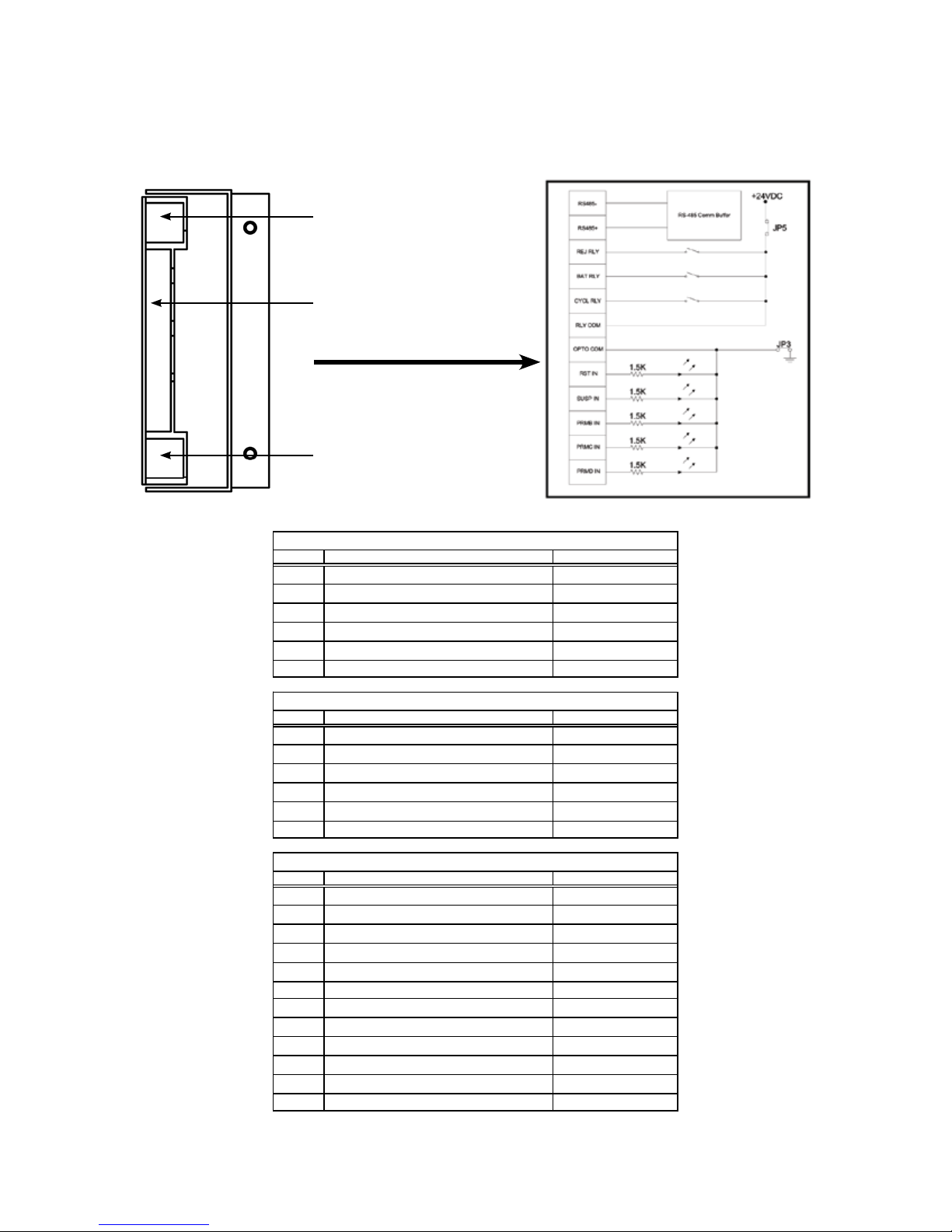
3.3.6 TVP-110-30 (230VAC) Input/Output Connectors
RS-232 Connection 9 pin D-SUB•
I/O Connector Amphenol 12 pin Circular Connector•
Transducer Connection Amphenol 4 pin Circular Connector•
PL12EN-TVP100
03/07/2013
12 Pin Connector Schematic
RS-232 Serial
Connector
12-Pin I/O
Connector
Pressure Transducer
Connector
RS 485 -
RS 485 +
Reject Relay
Batch Relay
Cycle Relay
+24VDC Relay Common
Ground / Opto Common
Reset
Suspend
Parameter B
Parameter C
Parameter D
RS 485
+24VDC
JP5
JP3
Press any key to continue.
Page 15

PL12EN-TVP100
Supplied
Internal
Supplied
External
A Black RS 485- -1 - 6.5V
B White RS 485+ -1 - 6.5V
C Red/White Reject Relay +24VDC
D Black/White Batch Relay +24VDC
E Blue/Black Cycle Relay +24VDC
F Green/White +24VDC/Relay Common +24VDC
G Blue/White Ground/Opto Common 0VDC
H Blue Reset 0V to 24V
J White/Black Suspend 0V to 24V
K Red/Black Parameter B 0V to 24V
L Green/Black Parameter C 0V to 24V
M Orange/Black Parameter D 0V to 24V
Pin #
Description
12 Pin Circular Input/Output Connector
100 mA
2.4 W
3 A
(70 W)
Load Maximum
Value
03/07/2013
Cleco
®
Pneumatic Torque Verifier TVP-100 Series
3.3.6 TVP-110-30 (230VAC) Input/Output Connectors (continued)
3.4 Decommissioning of Unit
Disconnect the power source. No additional procedures are required.
Page 16

4 Programming
4.1 Run Screen
The Run Screen is the main screen that will be used while the tool is in operation. This
screen contains a wealth of information about what is occurring in the assembly process
at any given time. From this screen a user can ascertain how many fasteners have been
completed towards a batch, the current application, the last fastener status, the pressure
within the tool, whether the unit is locked or un-locked, and the total number of batches
that have been completed.
Cleco
®
Pneumatic Torque Verifier TVP-100 Series
PL12EN-TVP100
03/07/2013
LED Indicator
Function
LED Indicator
Function
LED Indicator
Function
Current
Status
Number Completed
Toward Batch
RUN SCREEN
Cycle Count:
ACCEPT
BATCH
ACCEPT
Batch Total:
REJECT
SUSPEND
Cycle Accept
RESET
BATCH
UNLOCK
Soft Key Functions
Number in Batch
APPLICATION
of:
psi
Application in Use
Lock State
Pressure Inside Tool
Number of
Complete Batches
This screen automatically appears at the end of the power up sequence. This screen may
also be reached by selecting the “Run Screen” option from the navigation menu.
Run Screen
AutoCal
View Run
Statistics
Options
Select Application
Application Builder
Sequencing
Administration
I/O Schematic
Run Screen
Page 17
RUN SCREEN
Cycle Count:
ACCEPT
BATCH
ACCEPT
REJECT
SUSPEND UNLOCK
Cycle Accept
Batch Total:
RESET
BATCH
APPLICATION
of:
psi

PL12EN-TVP100
03/07/2013
4.2 Navigation Menu
The Navigation Menu is the leaping off point to all functions within this unit. The Ship’s
Wheel key may be pressed at any time, and the Navigation Menu will appear. From
the Navigation menu, the user can go to the Run Screen, perform an AutoCal, view a
rundown, review statistics, set the units options, select the application in use, adjust any
given application, enable sequencing, perform administrative functions, and look at a
schematic that aids in external wiring.
Cleco
®
Pneumatic Torque Verifier TVP-100 Series
4.3 AutoCal
In order for this unit to function properly, the thresholds and timers within the application
need to be set appropriately with regards to the tool’s pneumatic signature. The AutoCal
feature provides a very quick and easy means of performing this set-up. To reach the
AutoCal function, select “AutoCal” from the navigation menu.The Navigation Menu
If the unit was locked prior to making this selection, you’ll be prompted to enter the
password. The default password is “0 1 0 4”.
Run Screen
AutoCal
View Run
Statistics
Options
Select Application
Application Builder
Sequencing
Administration
I/O Schematic
Run Screen
AutoCal
View Run
Statistics
Options
AutoCal
Select Application
Application Builder
Sequencing
Administration
I/O Schematic
Please enter your password
to contonue.
TherstscreenassociatedwiththeAutoCalprocesswillinformtheuserthatthetoolmust
be off and also that they should press the “Next” key. This screen also reminds the user
which application set is active. The calibration will only effect that application. At this
point, make sure the transducer is connected to both the tool and the box and also that
the tool is not running. Then press the “Next” softkey.
AUTOCAL
Tool must be OFF.
Press NEXT to continue
the AutoCalibration
for Application A.
EXIT
Select
Application
0 1 0 4
NEXT
NEXT
Page 18

Pneumatic Torque Verifier TVP-100 Series
4.3 AutoCal (continued)
The second AutoCal screen will appear next. This screen will prompt the user to run a
typical fastener and then to press the “Next” softkey. When running a “typical” fastener,
the user should start with the tool off and then run the fastener to its completion allowing
the tool’s clutch to turn the tool off. The tool’s trigger should then be released and left
alone until the “NEXT” softkey is pressed on the unit.
After these steps are completed, the result of the calibration will appear on the screen.
Cleco
®
PL12EN-TVP100
03/07/2013
AUTOCAL
The Qualier will use the
last fastening cycle to
Run a sample fastener now.
Press NEXT to continue.
EXIT
If the calibration was not successful, check the tool and transducer connections. The
transducer needs to be properly connected to both the tool and this unit in order for the
system to function correctly.
The Run Screen may be used to determine if a pressure change is occurring while the
tool is running. When the tool if off, the pressure should be near to if not 0 psi. While the
tool is running, the pressure will be around 50 or 60 psi. When the clutch shuts the tool
off, the pressure will rise almost to line pressure.
It’s also very important that the appropriate tool type is selected. Pulse tools and direct
drive tools are monitored differently. Be sure that the appropriate tool has been selected
under the Options screen.
4.4 Viewing A Run
A graph of the last run down may be viewed by selecting the “View Run” option from the
navigation menu. Once again, you may be prompted to enter a password if the unit has
not been un-locked.
AutoCal.
OR
NEXT
Run Typical
Fastener
NEXT
AUTOCAL
Auto Calibration was successful.
Press NEXT to continue.
EXIT
NEXT
Run Screen
AutoCal
View Run
Statistics
Options
Select Application
Application Builder
Sequencing
Administration
I/O Schematic
While viewing a run, the “1” key may be pressed to draw and erase the thresholds and
timers. Pressing the “2” key will draw and erase the tool’s signature. If a new fastening
cycle is run, the “ENTER” key may be pressed to retrieve and view this new curve.
View Run
Page 19
AutoCal
Zoom
IN
Zoom
OUT
Application
Builder

PL12EN-TVP100
03/07/2013
4.5 Statistics
This unit will hold information pertaining to the last 1000 events. That information can
be viewed by going to the “Statistics” screen. In order to reach the “Statistics” screen,
highlight the Statistics option on the navigation menu and press “ENTER”.
Run Screen
AutoCal
View Run
Statistics
Options
TherearevecolumnsworthofinformationontheStatisticsscreen.Columnoneholds
the event number. The second column displays the application the unit was using when
that event occurred. The date and time that the even occurred is displayed in column
threeandcolumnfour.Columnveholdsadescriptionofthe event itself. The event
description will be a Cycle OK, a Batch OK or a Reject.
Cleco
®
Pneumatic Torque Verifier TVP-100 Series
Select Application
Application Builder
Sequencing
Administration
I/O Schematic
Statistics
EVENT APP MM/DD/YYYY HH:MM.SS STATUS
17 A 12/15/2011 11:14.21 Cycle OK
16 A 12/15/2011 11:13.42 Batch OK
15 B 12/15/2011 11:12.25 Reject T14 A 12/15/2011 11:12.34 Cycle OK
13 A 12/15/2011 11:10.32 Cycle OK
12 A 12/15/2011 11:08.21 Cycle OK
11 A 12/15/2011 11:07.23 Cycle OK
10 A 12/15/2011 10:22.15 Batch OK
9 A 12/15/2011 10:21.12 Cycle OK
8 A 12/15/2011 10:20.20 Cycle OK
7 A 12/15/2011 9:44.26 Cycle OK
Page
Page
UP
DOWN
Most
Recent
EXIT
The Cycle OK status tells you that a single fastening was completed properly. A Batch OK
tells you that a single fastening was completed properly and that it was the last fastener
in the batch. A Reject status informs the user that for some reason that fastening was
rejected. Each Reject status is accompanied with a reason to help you discern why that
fastening was rejected.
The soft-keys provide functions that allow a user to view more statistics than can be
showed on the screen at one time. The “Page Up” and “Page Down” soft-keys can be
pressed to view events that occurred further back in time or more recently. Pressing the
“Most Recent” soft-key will place the most recent event at the top of the screen and the
events that preceded it directly below.
Pressing the “Exit” soft-key or the Ship’s Wheel will take the unit back to the navigation
menu.
4.6 Options
Several user adjustable features can be accessed from the “Options” menu. In order to
reach the “Options” menu, highlight the Options button on the navigation menu and press
the “ENTER” key.
Run Screen
AutoCal
View Run
Statistics
Select Application
Application Builder
Sequencing
Administration
Options
OPTIONS MENU
1. Relays
2. Beeper
3. Parameter Switch Type
4. Time / Date
5. Tool Type
6. Adjust Display
Options
I/O Schematic
Save EXIT
Page 20

4.6.1 Relay Options
TherstitemontheOptionsscreenlistisRelays.Byselectingthisoptiontheusercan
choose to set the relays to “latching” or “momentary”. To select “Relays” from the Options
screen list either press the “1” key or highlight the “Relays” option and press “ENTER”.
Once at the “Relays Options” screen you can choose how the relay outputs are going
to act. If the relays are set to momentary, each time an event occurs the corresponding
relay will turn on for 200ms and then turn back off. If the relays are set to latching, the
appropriate relay will turn on and remain on when an event occurs. That relay will turn off
at the beginning of the next cycle (the next time the tool starts).
Cleco
®
Pneumatic Torque Verifier TVP-100 Series
RELAY OPTIONS
1. Momentary
2. Latching
Select EXITUp Down
PL12EN-TVP100
03/07/2013
To make a selection on this screen, the number key that corresponds with the selection
may be pressed. If you use this number key method, the selection will be made and
stored. The screen will also return to the “Options” menu.
A selection may also be made by using the arrow keys or the “UP” and “DOWN” soft-keys
to highlight the desired selection and then pressing the “Select” soft-key.
The “EXIT” soft-key, the “Ship’s Wheel”, or the “ESC” key may be pressed to return to the
“Options” screen without making and storing a new selection.
4.6.2 Beeper Options
The second item on the Options screen list is Beeper. The unit can be programmed to
double-beep or be silent upon the completion of a batch. In order to choose the Beeper
option either press the “2” key or highlight the Beeper option using the Arrow keys and
then press “ENTER”.
BEEPER OPTIONS
1. Double beep on Batch Accept
2. Beep on Reject only.
Select EXITUp Down
To make the box double-beep on a batch accept, either press the “1” key at the Beeper
Options screen or highlight the “Double Beep” option and press the “Select” soft-key.
If a double-beep is not desired either press the “2” key at the Beeper Options screen or
highlight the “Beeper on Reject” option and press the “Select” key.
Page 21

PL12EN-TVP100
Param D Param C Param B Application Application
INPUT INPUT INPUT (Binary) (Discrete)
OFF OFF OFF A A
OFF OFF ON B B
OFF ON OFF C C
OFF ON ON D C
ON OFF OFF E D
ON OFF ON F D
ON ON OFF G D
ON ON ON H D
03/07/2013
Pneumatic Torque Verifier TVP-100 Series
4.6.3 Application Select Input
Applications can be selected through external inputs. These inputs can be used in two
different schemes. The inputs can either select one of four different applications. Or,
when set to “binary”, these three inputs can be used to select eight different inputs.
Binary(1of8)istherstoptiononthe“ApplicationsSelectInputs”screen.Inorderto
choose this option either press the “1” key at this screen or highlight the option and press
the “Select” soft-key.
Cleco
APPLICATION SELECT INPUTS
1. Binary, 1 of 8
2. Discrete, 1 of 4
®
Select EXITUp Down
If discrete (1 of 4) is how you would prefer to select applications either press the “2” key
or highlight this option and press the “Select” soft-key.
Page 22

4.6.4 Time and Date
This unit will keep track of the current time and date even when the unit is turned off.
Each time an event occurs (like an accept or reject), that event is stored in memory along
with a time and date stamp.
The time and date may be edited by pressing the “4” key at the Options screen or by
highlighting the “Time / Date” element and pressing the “Select” soft-key.
Once at the TIME / DATE edit screen, the left and right arrows may be used to select a
character within the time or date. Once the desired character is highlighted the number
keys may be used to alter its value.
Cleco
®
Pneumatic Torque Verifier TVP-100 Series
TIME / DATE
Enter the time and date in the
format: YYY/MM/DD HH:MM.SS
2011/06/16 13:41.24
The change will not occur
until the unit is powered down.
Save EXIT
PL12EN-TVP100
03/07/2013
Once the time and date are set to the desired value, either the “Save” soft-key or the
“ENTER” key may be pressed to save the new value. If a new value is saved, the unit will
have to be powered down and powered back up again before the changes take effect.
TIME / DATE
2011/06/16 13:41.24
Please turn the power switch OFF.
Save EXIT
To leave the TIME / DATE screen without making any changes either the “EXIT” soft-key
or press the “ESC” key.
Page 23

PL12EN-TVP100
03/07/2013
4.6.5 Tool Type
It is very important to select the correct tool type for the application. There are three
differentchoicesformonitoringtoolswithinthisunit.TherstchoiceisPulsePneumatic
and should be used for monitoring most Pulse Tools. When set to Pulse Pneumatic, this
unitwillnotonlyusethetimersandthresholds,thisunit willactuallycountandconrm
that pulses occurred.
The Direct-drive Pneumatic is used for monitoring pneumatic clutch tools that do not
pulse.
The 7/11 PTH mode is a combination of Pulse Pneumatic and Direct-drive Pneumatic.
TosetToolType,fromtheOptionsScreenselectthefthoption(ToolType)bypressing
the 5 key or highlight the option and press “ENTER”. The Tool Type screen will appear
at this point. If a Pulse tool (20Nm or larger) is to be monitored, option one (Pulse
Pneumatic) should be selected. Select option three (7/11 PTH) for smaller pulse tools.
For all other pneumatic tools option two (Direct-drive Pneumatic) should be selected.
Cleco
®
Pneumatic Torque Verifier TVP-100 Series
TOOL TYPE
1. Pulse Pneumatic
2. Direct-drive Pneumatic
3. 7/11 PTH
Pressing the numeric key associated with the desired option (either “1”, “2” or “3”) will
select and write that option to memory. Alternatively, your option can be highlighted and
then “ENTER” can be pressed to make a selection.
4.6.6 Adjusting The Display
The unit’s display is set for optimal viewing at the factory. However, it may be necessary
at some point to make the display darker or lighter for easier viewing. If the display needs
adjusted, option six can be selected from the Options menu by either pressing the “6” key
or by highlighting the option and pressing “ENTER”.
The arrow keys are used to alter the display from the Adjust Display screen. Once the
display has the desired appearance, press the “EXIT” soft-key to return. The default
LCD values can be re-written if the “.” button is pressed during the power-up screen or at
the “Run” screen.
Select EXITUp Down
ADJUST DISPLAY
Less Contrast More Contrast
Light
Dark
highlighted text
selected text
EXIT
Page 24

Pneumatic Torque Verifier TVP-100 Series
4.7 Selecting Application
An application is a set of parameters that governs how a given tool is monitored. There
are two different ways to choose which application is in use. One way is through external
inputs. The other method can be accomplished through the keypad. A dip-switch inside
the box controls which method can be used.
If dip-switch one on the backboard is in the “ON” position, then applications can be selected
through the keypad. In order to change the application, go to the navigation menu and
choose “Select Application”.
On the “Select Application” screen, an arrow will point to indicate which application is
currently selected. To change this selection, you can press the number on the keypad
that is associated with the application you want to select. Or, you can highlight the desired
selection with the arrow keys and then press the “Select” soft-key.
Cleco
SELECT APPLICATION
1. A
2. B
3. C
4. D
5. E
6. F
7. G
8. H
®
Select EXIT
PL12EN-TVP100
03/07/2013
To leave this screen without making any changes, the “EXIT” soft-key can be pressed or
the “ESC” key can be pressed. The “Ship’s Wheel” has no effect at this screen.
4.8 Application Builder
An application is a set of timers, thresholds, and a batch value that are used in monitoring
the pneumatic tool. The best way to develop these values it to make use of the AutoCal
feature. By using AutoCal, the timers and thresholds will be generated automatically for
any given application.
A situation may arise where these values need to be manipulated manually. If so, select
the “Application Builder” option from the navigation menu. This action will take the unit to
the “Application Builder” screen.
APPLICATION BUILDER
Application
Th1 Noise Floor
Th2 Run Start
Th3 Shut-off Threshold
T- Minimum Run Time
T+ Maximum Run Time
Tc Clutch Timer
Tb Bump Timer
Fasteners per Batch
Total Completed Batches:
Page 25

PL12EN-TVP100
Application Element Description
Th1 Noise Floor
Pressure threshold that sets a pressure level for the unit to begin capturing
data
Th2 Run Start
Pressure threshold that sets a pressure level which after crossed a status
will be generated (either accept or reject).
Th3 Shut-off Threshold
Pressure threshold that sets a pressure level above which the tool is
considered to have "clutched" out. Th3 is a defined pressure increment
above the pulsing (or tightening) pressure.
Thd Dynamic Threshold
Th3 pressure level as it is displayed on oscilloscope. It is called
dynamic pressure because it rises/falls with line pressure.
T- Minimum Run Time
Minimum amount of time the tool must run before clutching out
without generating a reject.
T+ Maximum Run Time
Maximum amount of time tool can run before clutching out without
generating a reject.
Tc Clutch Timer
Amount of time user must hold tool trigger after tool clutches out
without generating a reject.
Tb Timer Bump
Timer used to cancel incidental runs in the case of a push to start
tool. If this timer is violated without the clutch firing, no status will be
generated. AutoCal sets this time to 0.
Fasteners per Batch
Number of fasteners associated with a batch. Every time this number
of fasteners is completed, a Batch Accept will be generated.
Total Completed Batches
This number represents the number of batches that have been
completed.
03/07/2013
Pneumatic Torque Verifier TVP-100 Series
4.8 Application Builder (continued)
To edit an item from the Application Builder, highlight the item you want to edit and then
press “ENTER”. A cursor will appear. While that cursor is highlighting a digit, use the
numeric keypad to alter its value or use the left and right arrows to select a different
character.
Cleco
®
The“ESC”keywillstopthecursorfromashingandallowyoutoselectadifferentelement
to be edited.
The “SAVE” soft-key must be pressed in order to save any changes made within the
Application Builder. The “EXIT” soft-key will allow a user to leave the Application Builder
without making any changes.
The “Globalize” soft-key allows you to copy an application to all of the other applications.
The “Clear Total” soft-key sets the total back to zero.
Page 26

4.9 Sequencing
This unit has the ability to automatically switch from application to application if the
“Sequencing” feature is enabled. If Sequencing is enabled, the unit will start in Application
A. Once the batch is complete in Application A, the unit will automatically switch to
Application B. This switching from application to application will continue upon the
completion of each batch until the end application is reached.
Once the end application is reached and the batch is completed, a batch accept will be
generated and the unit will revert back to Application A. The batch accept output will only
begeneratedonthenalapplicationinthesequence.
In order to program the Sequence function, select the “Sequencing” item from the
navigation menu.
Cleco
®
Pneumatic Torque Verifier TVP-100 Series
SEQUENCING
OFF
A-B
A-C
A-D
A-E
A-F
A-G
A-H
PL12EN-TVP100
03/07/2013
Using the arrow keys or the “UP” and “DOWN” soft-keys, you can highlight the type of
sequencing you wish to employ. Once the desired selection is highlighted, pressing the
“Select” soft-key will move the arrow to indicate that the selection has changed.
The “EXIT” soft-key, the “ESC” key, and the “Ship’s Wheel” will all take the unit back to
the navigation menu.
4.10 Administration
The unit’s password can be altered from the Administration screen. To alter the unit’s
password, choose “Administration” from the navigation menu. There are only two options
on the Administration screen, one is “Change Password” and the other is “Exit”. Choose
the “Change Password option by highlighting it and pressing the “ENTER key.
ADMINISTRATION
Change Password
EXIT
EXIT
Select EXIT
CHANGE PASSWORD
Please enter a new four-digit
password:
EXIT
CHANGE PASSWORD
Please conrm your new password.
Conrm:
EXIT
Page 27

PL12EN-TVP100
03/07/2013
Pneumatic Torque Verifier TVP-100 Series
4.10 Administration (continued)
After “ENTER” is pressed, a screen will appear prompting you to enter a new four-digit
password. Use the numeric keypad to enter this new code or press the “Exit” soft-key to
escape without changing the password.
Once the new four-digit code is entered, the unit will prompt you to conrm this four
digit code. If you enter the same code the second time, the unit will politely ask you to
remember your new password. If for some reason the same code is not entered twice,
theunitwillinformyouthatyourconrmationfailed.
In either case, after a short delay, the unit automatically returns to the navigation menu.
4.11 I/O Schematic
The nal option on thenavigation menuis “I/OSchematic” ifthis option is selected a
schematic appears on the screen which shows the function of the 12-pin I/O connector
and the circuitry behind it.
Pressing any key while the schematic is being displayed will return the unit to the navigation
menu.
Cleco
®
12 PIN CONNECTOR SCHEMATIC
+ RS485
- RS485
REJECT RELAY
BATCH RELAY
CYCLE RELAY
+24VDC/RLY COM
GND/OPTO COM
RESET INPUT
SUSPEND INPUT
PARAM B INPUT
PARAM C INPUT
PARAM D INPUT
PRESS ANY KEY TO CONTINUE
RS 485
+24VDC
JP5
JP3
Please note that jumpers JP3 and JP5 from the diagram above are not connected when
the unit ships.
Page 28

Pneumatic Torque Verifier TVP-100 Series
A Appendix
A.1 Pneumatic Curves (Pulse Tool)
Good Run Down:
Analog CH1 Analog CH2
Free Run
Pulsing Region
Cleco
®
Pulse Tool Good Run
PL12EN-TVP100
03/07/2013
Clutch-Out
Region
% Full Scale
Time (in seconds)
This picture shows the analog data from a good fastening process using a pulse tool.
There are a few hallmarks in this curve that are worth noticing. This tool was set up to
pulse at least four times. If the tool does not pulse at least four times, there is a good
chance that it will generate reject statuses.
Also, at the end of the pulsing phase, the pressure steps up almost to line level. This
region indicates the tool’s clutch shut the tool off when torque was achieved.
Page 29

PL12EN-TVP100
03/07/2013
Cleco
®
Pneumatic Torque Verifier TVP-100 Series
A.1 Pneumatic Curves (Pulse Tool) (continued)
Incomplete Run Down:
Pulse Tool No Clutch
Analog CH1 Analog CH2
% Full Scale
Time (in seconds)
This picture shows the curve generated by an incomplete fastening process. Notice how
the curve does not step up to line pressure at the end of the run. This indicates that the
clutch did not engage.
Page 30

Cleco
®
Pneumatic Torque Verifier TVP-100 Series
A.1 Pneumatic Curves (Pulse Tool) (continued)
Double-Hit:
Pulse Tool Double Hit
Analog CH1 Analog CH2
% Full Scale
PL12EN-TVP100
03/07/2013
Time (in seconds)
This picture shows the curve generated by a double hit. Notice how the curve immediately
steps up to line pressure and stays there. There is little or no pulsing region. This curve
would be typical of a fastener being “hit” again after the fastener had already been
tightened to torque.
Page 31

PL12EN-TVP100
03/07/2013
Cleco
Pneumatic Torque Verifier TVP-100 Series
A Appendix
A.2 Pneumatic Curves (Direct Drive Tool)
Good Run Down:
Direct Drive Good Run-Down
Analog CH1 Analog CH2
Free Run
®
Clutch-Out
Region
% Full Scale
Time (in seconds)
This picture shows the analog data from a good fastening process using a direct drive
tool. There are two hallmarks in this curve worth noticing. First, during free run the tool
runs at a constant pressure which is lower than the shut-off or clutch-out pressure. Then,
after the tool’s clutch engages the pressure steps up to near line pressure.
Page 32

Cleco
®
Pneumatic Torque Verifier TVP-100 Series
A Appendix
A.2 Pneumatic Curves (Direct Drive Tool) (continued)
Incomplete Run Down:
Direct Drive No-Clutch
Analog CH1 Analog CH2
PL12EN-TVP100
03/07/2013
% Full Scale
Time (in seconds)
This picture shows the curve generated by an incomplete fastening process. Notice how
the curve does not step up to line pressure at the end of the run. This indicates that the
clutch did not engage.
Page 33

PL12EN-TVP100
03/07/2013
Cleco
®
Pneumatic Torque Verifier TVP-100 Series
A Appendix
A.2 Pneumatic Curves (Direct Drive Tool) (continued)
Double-Hit:
Direct Drive Double-Hit
Analog CH1 Analog CH2
% Full Scale
Time (in seconds)
This picture shows the curve generated by a double hit. Notice how the curve immediately
steps up to line pressure and stays there. There is no free run region. This curve would
be typical of a fastener being “hit” again after the fastener had already been tightened to
torque.
Page 34

A Appendix
A.3 Box Dimensions
Cleco
®
Pneumatic Torque Verifier TVP-100 Series
8.75” (222)
PL12EN-TVP100
03/07/2013
8.00”
(203)
4.00” (102)
A.4 Tool and Box Diagram
Tool
Air Signal
(from Porting)
(includes cable and air hose)
Main Air
Transducer
207237 - 115V
207238 - 230V
Air Hose
9.125”
(232)
8.375” (213)
To Compressor
Phone Cable
Page 35

PL12EN-TVP100
Position ON Off
1. Parameter Selection Software Select External Input Selection
2. No Function
3. No Function
4. Test Mode Test Mode ON Normal Operation
5. Test Selection 1 See Below See Below
6. Test Selection 2 See Below See Below
7. Beeper Beeps ON Beeps OFF
8. RS-485 Terminator Termination ON Termination OFF
DIP5 DIP6 FUNCTION
OFF OFF Digital Outputs Test (each output is turned on one at a time)
OFF ON Digital Inputs Test (digital input will appear as a segment on bar LED)
ON OFF Analog Test CH0 (analog input on CH0 will appear as % on bar LED)
ON ON Analog Test CH1 (analog input on CH1 will appear as % on bar LED)
1 2 3 4 5 6 7 8
ON
Dip-Switch Settings
03/07/2013
Pneumatic Torque Verifier TVP-100 Series
B Appendix
B.1 Dip-Switch Settings
The dip-switch (located in the corner on the CE2731 board) controls certain aspects of
the units functionality. Those functions are listed below.
Cleco
®
B.2 Test Modes
When dip-switch four is in the ON position, the backboard (CE2731) enters a test mode.
The possible tests are as follows:
Page 36


Sales & Service Centers
Note: All locations may not service all products. Please contact the nearest Sales & Service Center for
the appropriate facility to handle your service requirements.
Detroit, MI Houston, TX Lexington, SC Los Angeles, CA
Apex Tool Group Apex Tool Group Apex Tool Group Apex Tool Group
Sales & Service Center Sales & Service Center 670 Industrial Drive Sales & Service Center
2630 Superior Court 6550 West Sam Houston Lexington, SC 29072 6881 Stanton Avenue
Auburn Hills, MI 48326 Parkway North, Suite 200 Tel: 800-845-5629 Unit B
Tel: 248-393-5640 Houston, TX 77041 Tel: 803-951-7544 Buena Park, CA 90621
Fax: 248-391-6295 Tel: 713-849-2364 Fax: 803-358-7681 Tel: 562-623-4457
Fax: 713-849-2047 Fax: 562-802-1718
Seattle, WA York, PA Canada Germany
Apex Tool Group Apex Tool Group Apex Tool Group Apex Tool Group
Sales & Service Center Sales & Service Center Sales & Service Center GmbH & Co. OHG
2865 152nd Avenue N.E. 3990 East Market Street 5925 McLaughlin Road Industriestraße 1
Redmond, WA 98052 York, PA 17402 Mississauga, Ont. L5R 1B8 73463 Westhausen
Tel: 425-497-0476 Tel: 717-755-2933 Canada Germany
Fax: 425-497-0496 Fax: 717-757-5063 Tel: 905-501-4785 Tel: +49 (0) 73 63 81 0
Fax: 905-501-4786 Fax: +49 (0) 73 63 81 222
England France China Mexico
Apex Tool Group Apex Tool Group S.N.C. Cooper (China) Co., Ltd. Cooper Tools
GmbH & Co. OHG 25 rue Maurice Chevalier a company of de México S.A. de C.V.
C/O Spline Gauges B.P. 28 Apex Tool Group, LLC a company of
Piccadilly, Tamworth 77831 Ozoir-La-Ferrière 955 Sheng Li Road, Apex Tool Group, LLC
Staffordshire B78 2ER Cedex, France Heqing Pudong, Shanghai Vialidad El Pueblito #103
United Kingdom Tel: +33 1 64 43 22 00 China 201201 Parque Industrial Querétaro
Tel: +44 1827 8741 28 Fax: +33 1 64 43 17 17 Tel: +86-21-28994176 Querétaro, QRO 76220
Fax: +44 1827 8741 28 Fax: +86-21-51118446 Mexico
Tel: +52 (442) 211-3800
Fax: +52 (442) 103-0443
Brazil Hungary
Cooper Tools Industrial Ltda. Apex Tool Group
a company of Hungaria Kft
Apex Tool Group, LLC Platànfa u.2
Av. Liberdade, 4055 9027 Györ
Zona Industrial - Iporanga Hungary
18087-170 Sorocaba Tel: +36 96 66 1383
SP Brazil Fax: +36 96 66 1135
Tel: +55 15 2383929
Fax: +55 15 2383260
Apex Tool Group, LLC
1000 Lufkin Road
Apex, NC 27539
Phone: 919-387-0099
Fax: 919-387-2614
www.apextoolgroup.com
PL12EN-TVP100/Printed in USA 03/2013/Copyright © Apex Tool Group, LLC
 Loading...