


Electric Tool Control
TME Series
Version 2.5.2
Reference Document: PL12-1404 Parts manual
For additional product information visit our website at http://www.cooperpowertools.com
Programming Manual
PL12EN-1300
2008-03

2 PL12EN-1300 2008-03 en00d141.fm, 11.03.2008
Disclaimer:
The information and data in this document has been prepared to the best of our ability.
Nonetheless, differences between the information and the actual product cannot be
excluded with absolute certainty. Cooper
Power Tools does not assume any liability for
consequential errors and damages. We likewise do not assume liability for damages
resulting from defective circuitry inside the devices supplied. Cooper
Power Tools
reserves the right, to ammend, supplement or improve this document or the product with
-
out serving prior notice.
Without the express approval of Cooper Power Tools this document must not be reproduced in its entirity or in part by any means; it must not be converted to any type of natural or machine readable language or be saved on data storage media of electronic,
mechanic, optical or other type.

PL12EN-1300 TME-200 V2.5 .2 0108IVZ.fm, 11.03.2008 PL12EN-1300 2008-03 3
Contents
1 Getting Started 7
1.1 Safe Work Practices Symbol ................................................................ 7
1.2 Checking Your Unit ............................................................................... 7
1.3 Software................................................................................................ 7
1.4 Installing Unit ........................................................................................ 7
1.4.1 General ................................................................................................. 7
1.4.2 Mounting ............................................................................................... 8
1.4.3 Location Considerations ....................................................................... 8
1.4.4 Source Power ....................................................................................... 8
1.4.5 Intended Use ........................................................................................ 8
1.4.6 EMC Measures ..................................................................................... 9
1.5 Connecting Unit .................................................................................... 9
1.5.1 General ................................................................................................. 9
1.6 Energizing Unit ................................................................................... 10
2 Controller Specifications 13
2.1 Understanding the Keypad ................................................................. 13
2.2 Specifications...................................................................................... 14
2.2.1 Enclosure............................................................................................ 14
2.2.2 Display ................................................................................................ 14
2.2.3 Keypad Overlay .................................................................................. 15
2.2.4 Indicators ............................................................................................ 15
2.2.5 CPU with PC 104................................................................................ 15
2.2.6 AC Input Power................................................................................... 16
2.2.7 Inernal DC Power ............................................................................... 16
2.2.8 Input / Output Connectors................................................................... 16
3 Programming 21
3.1 Navigator Menu .................................................................................. 21
3.1.1 Basic Navigation Instructions.............................................................. 21
3.1.2 Work Cell ............................................................................................ 21
3.1.3 Password Function ............................................................................. 22
3.1.4 Print Screen ........................................................................................ 22
3.1.5 Two Channel Features: General Description
(2-Channel V2.xx.xx C2 only) ............................................................. 22
3.1.6 Navigator Menu .................................................................................. 23
3.1.7 Administration ..................................................................................... 24
3.2 Basic Application Builder .................................................................... 24
3.2.1 Basic Parameters for Torque Control / Angle Monitor ........................ 26
3.2.2 Basic Parameters for Angle Control / Torque Monitor ........................ 26
3.2.3 Basic Application Builder Parameters................................................. 26
3.2.4 Advanced Parameter Default Values.................................................. 27

4 PL12EN-1300 2008-03 PL12EN-1300 TME-200 V2.5.2 0108IVZ.fm, 11.03.2008
3.2.5 Backoff using Reverse Switch (Sequence 41 or Sequence 46) ......... 27
3.2.6 Basic Application Builder / Auto Program ........................................... 27
3.2.7 Basic Application Builder / Copy......................................................... 28
3.3 Standard Application Builder............................................................... 29
3.3.1 Standard Application Builder / View Stages........................................ 29
3.3.2 Standard Application Builder / View Stages / Copy ............................ 30
3.3.3 Standard Application Builder / Select Sequence ................................ 31
3.3.4 Standard Application Builder / Parameters......................................... 33
3.3.5 Standard Application Builder / Advanced Parameters........................ 38
3.4 Advanced............................................................................................ 40
3.4.1 Advanced Application Builder / Application Matrix.............................. 40
3.4.2 Advanced Application Builder / Inputs ................................................ 41
3.4.3 Advanced Application Builder / Outputs ............................................. 43
3.4.4 Advanced Application Builder / Fieldbus ............................................ 46
3.4.5 Advanced / Linking ............................................................................. 51
3.4.6 Advanced Application Builder / Signals .............................................. 52
3.4.7 Advanced Application Builder / System Settings ................................ 53
3.5 RUN Screen........................................................................................ 55
3.5.1 Run Screen / Tool 2 ............................................................................ 57
3.5.2 Run Screen / Split Screen................................................................... 57
3.5.3 Run Screen / TMEI ............................................................................. 58
3.5.4 Run Screen / Configure ...................................................................... 59
3.6 Oscilloscope ....................................................................................... 60
3.7 Communication................................................................................... 61
3.7.1 Communications / Data Transmission ................................................ 61
3.7.2 Communication / Part ID..................................................................... 64
3.7.3 Communications / Printer ................................................................... 67
3.7.4 Communications / Work Cell .............................................................. 68
3.8 Tool Setup........................................................................................... 68
3.9 Tool Library ......................................................................................... 70
3.9.1 Tool Library ......................................................................................... 70
3.10 Statistics.............................................................................................. 71
3.10.1 Statistics / Chronological History ........................................................ 71
3.10.2 Statistics / Graphs............................................................................... 73
3.10.3 Statistic / Parameter............................................................................ 75
3.11 Diagnostics ......................................................................................... 76
3.11.1 Inputs / Outputs .................................................................................. 76
3.11.2 Diagnostic / Fieldbus .......................................................................... 77
3.11.3 Tool / Calibration ................................................................................. 78
3.11.4 Tool / Angle Encoder........................................................................... 79
3.11.5 Tool / Voltages .................................................................................... 80
3.11.6 Tool / TQ Measurement ...................................................................... 81
3.11.7 Tool / Speed........................................................................................ 82
3.11.8 Tool / Tool Memory.............................................................................. 83
3.11.9 Arcnet / Map ....................................................................................... 83
3.11.10 Arcnet / Statistic.................................................................................. 84

PL12EN-1300 TME-200 V2.5 .2 0108IVZ.fm, 11.03.200 8 PL12EN-1300 2008-03 5
3.11.11 Serial................................................................................................... 85
3.11.12 Event Log............................................................................................ 86
3.12 Utilities ................................................................................................ 87
3.12.1 Utilities / Installed Versions................................................................. 87
3.12.2 Utilities / Software Update .................................................................. 88
3.12.3 Utilities / System Settings ................................................................... 90
3.13 Administration ..................................................................................... 91
3.13.1 Administration / Load/Save................................................................. 91
3.13.2 Administration / Print........................................................................... 92
3.13.3 Administration / Password .................................................................. 93
3.13.4 Administration / Date & Time .............................................................. 94
3.13.5 Administration / Language .................................................................. 95
3.13.6 Administration / Counter ..................................................................... 96
4 Statistics 97
4.1 Understanding Statistics ..................................................................... 97
4.1.1 The Nature of Variation....................................................................... 97
4.1.2 The Normal Curve .............................................................................. 98
4.1.3 The Procedure.................................................................................... 98
4.1.4 System Improvement........................................................................ 102
4.2 Statistic Symbols............................................................................... 102
5 Glossary 105

6 PL12EN-1300 2008-03 PL12EN-1300 TME-200 V2.5.2 0108IVZ.fm, 11.03.2008

en01d141.fm, 11.03.2008 PL12EN-1300 2008-03 7
Getting Started
1
1 Getting Started
1.1 Safe Work Practices Symbol
!
The signal word "Warning" identifies all notes on safe work practices in this operating
instruction, alerting to hazards for life and health of people. Observe these notes and proceed with special care in the cases described. Pass all safety instructions on to other
operators. In addition to the safety instructions in this operating instruction, the general
local safety and accident prevention rules must be observed.
CAUTION!
The signal word "Caution!" identifies all portions of this operating instruction meriting
special attention to ensure that guidelines, rules, hints and the correct work procedures
are observed; and, to prevent damage to and destruction of the machine and/or parts.
1.2 Checking Your Unit
Take the time to ensure you have the required peripheral equipment and cables necessary to
setup and run your unit. If you do not have all the necessary items, contact your distributor.
Refer to "Attachment A.1" on page12 for illustration of your unit.
1.3 Software
Your unit has been pre-loaded with software and requires no additional software to begin your
fastening process. If you are interfacing your unit with an external computer, interfacing software
is required. Contact your distributor for the interfacing software.
1.4 Installing Unit
1.4.1 General
!
It is mandatory that national, state and local safety and wiring standards be followed during installation. These standards would take precedence over any information presented
in this section.
To avoid the hazard of electrical shock or burn, the following instructions must be
adhered to. Failure to follow these instructions may also cause damage to your unit and
void existing warranties.
• Do not energize the unit until all connections have been properly made.
• Equipment must be properly grounded before applying power. Units energized by cord
and plug must be connected to an approved and properly grounded receptacle.
• All units must be energized by an isolated line.
• The unit door must always be closed and secured prior to energizing the unit.
• Ensure the power switch is in the "off" position prior to connecting the power cord.
CAUTION!
Though it is not mandatory, the following instructions are highly recommended for the
protected operation of your unit.
• Use an isolation transformer and surge arrestor on the incoming isolated line.
• Use oversized feeder lines to reduce electrical noise and voltage drop.

8 PL12EN-1300 2008-03 en01d141.fm, 11.03.2008
Getting Started
1
1.4.2 Mounting
Each unit is used primarily as a single tool process/controller/monitor installed in a work station
or work area. It may be wall mounted, table mounted, beam mounted, suspended overhead,
pedestal mounted or used without mounting. Always choose a stable location to avoid the possi
bility of unit damage and/or operator injury through hitting, falling, vibration or inconvenient
mounting. All cables attached to the unit should be located and secured in a manner to avoid
potential operator and passer-by injury. As with all electrical equipment, the unit will produce
some heat and should be located so that ambient air can freely circulate around the box.
Refer to Illustration Q of the parts manual, PL12-1400 for mounting hole dimensions.
1.4.3 Location Considerations
Your unit should be located to allow access to the front panel and connectors. The unit should be
installed for unrestricted and comfortable viewing of the LCD & LED's by the operator. The LCD
menu screen, key pad and side door connectors must be readily accessible for the setup.
Dependent on the peripheral equipment purchased, the unit may be located in a remote position
but should still be accessible.
Attachment of accessories and tools should also be considered with the installation locations.
Items to be considered are:
• Location of printer (10 ft. cable maximum for the parallel interface).
• Attachment of a data collection unit, if desired.
• Attachment of redundant master transducers (less than 50 ft. is desirable).
• Attachment of remote annunciators, socket nest, or remote parameter select.
• Attachment of the unit in a network to a computer.
• Operation convenience/safety - keep cables off the floor or dangling in operator areas.
1.4.4 Source Power
Your unit, which is used as the process control and power supply for the Cleco DC electric tools,
requires a power line with 10 amp capacity at 220-240 Volts AC (50/60 Hz) for the TME-XXX-30.
The TME-XXX-15 requires a power line with 15 amp capacity at 110-130 Volts AC (50/60 Hz).
1.4.5 Intended Use
The Electric Tool Control TME Series must be operated only if the following conditions are
met:
• Industrial environment, EMC (electromagnetic compatibility) class A
• Use only the cable types approved by Cooper Power To ol s .
• Use only accessory parts approved by Cooper Power Tools.
• Unauthorized remodeling, repairs, and modifications are forbidden for safety and product lia-
bility reasons.

en01d141.fm, 11.03.2008 PL12EN-1300 2008-03 9
Getting Started
1
1.4.6 EMC Measures
• The filters required to meet the EMC regulations are integrated.
• The closed control cabinet and the shielded cables result in very low noise radiation and high
immunity to interference.
• The following relevant EMC regulations are met:
-EN 61000-6-4: 08-2002
-EN 61000-6-2: 08-2002
-EN 61000-3-2: 2000
-EN 61000-3-3: 1995
• This is a class A device. In domestic areas, this device can cause radio interference. If
that is the case, the company operating it, can be obliged to introduce EMC measures
and cover the cost incurred.
• Operation without closed control cabinet is forbidden.
The properties of the shielding would be altered and the noise emission increase.
1.5 Connecting Unit
1.5.1 General
Connect all equipment to the correct input and output connectors. Refer to "Attachment A.1" on
page12 for proper port locations.
!
To avoid the hazard of electrical shock or burn the following instructions must be adhered
to. Failure to follow these instructions may also cause damage to your unit and void existing warranties.
• Ensure the power switch is in the "off" position and that the box cover is properly
secured prior to connecting power cord.
• Ensure equipment has been properly grounded before applying power.

10 PL12EN-1300 2008-03 en01d141.fm, 11.03.2008
Getting Started
1
1.6 Energizing Unit
!
To avoid the hazard of electrical shock or burn the following instructions must be adhered
to. Failure to follow these instructions may also cause damage to your unit and void existing warranties.
Upon application of power, the unit will initiate a self test. The initialization takes approximately
45 seconds.
The introduction screen shown below will be displayed for approximately 10 seconds and then
the Run Screen will be displayed.
c00276de.bmp
Fig. 1-1: Introduction Screen for TME-100
c00418de.bmp
Fig. 1-2: Introduction Screen for TME-200

c00407en.bmp
en01d141.fm, 11.03.2008 PL12EN-1300 2008-03 11
Getting Started
1
Fig. 1-3: Run Screen
Press the Ship‘s wheel to display the Navigator Menu. After the Navigator Menu is displayed,
verify the Tool Memory by entering Tool Setup. If Tool Memory is not active then select a tool
using the Tool Library. Press the ship's wheel to return to the Navigator Menu.
Once Tool Setup is complete the application needs to be programmed. To do this, go to Basic
Application Builder. From this screen torque, angle, and speed parameters must be entered for
the selected application. Press the ship's wheel to return to the Navigator Menu.
The controller is now ready to begin fastening cycles. The torque and angle data can be viewed
by pressing the Run Key. Tool and controller indicator lights will illuminate according to the
results.

12 PL12EN-1300 2008-03 en01d141.fm, 11.03.2008
Getting Started
1
Attachment A.1
Mounting Plate
Side Door Assembly
Connector Panel
Enclosure Key
(542818)
Indicator Lights
Keypad
Indicator Lights
LCD Display
a00254_1.bmp
Fig. 1-4: Controller
.1 .1
Tool Connectors
Floppy Drive
Power In
Fuse Holder
Ethernet Port
Keyboard Port
Printer Port
USB Port
Serial Ports
I/O Inputs
I/O Outputs
Power Disconnect
a00255_1.bmp
Fig. 1-5: Connector Box Detail

en02d141.fm, 11.03.2008 PL12EN-1300 2008-03 13
Controller Specifications
2
2 Controller Specifications
2.1 Understanding the Keypad
The following is a brief explanation of the keypad keys. You will need to become familiar with
these keys so you can smoothly program your unit.
Soft Keys (F1-F4) - used to select functions based on the screen displayed.
ESC Key - used at any time to return back one screen or exit the edit mode.
DEL Key - used to delete a numerical value on the LCD screen.
Arrow Keys - used to move the orange highlight around the screen.
ENTER Key - used to accept an answer/value on the LCD screen.
Ships Wheel - used at any time to return to the navigator menu.
Run - used at any time to return to Run Screen.
Soft Keys
Ship´s Wheel

14 PL12EN-1300 2008-03 en02d141.fm, 11.03.2008
Controller Specifications
2
2.2 Specifications
2.2.1 Enclosure
Model Weight* Width Height Depth
lb kg in mm in mm in mm
TME 80 36.4 16.5 419.1 17.5 444.5 12.3 312.4
* Mounting plate adds weight of 7 lbs / 3.2 kg and depth of 1.62 in / 41.1 mm
• Designed for NEMA 13/IP54 rating
• Lockable front door for customer specific key requirements
• Lockable 3-phase power switch
• Side door for connector/cable protection
• Removable Mounting Plate
• Removable, fully operational internal chassis (TME-100 only)
• Conductive front door gasket and lip to meet EMI regulations
• Orange textured powder coat
2.2.2 Display
• 7.7" in Passive Matrix Color LCD Module (TME-100);
6.5" in Passive Matrix Color LCD Module (TME-200)
• 640 x 480 resolution
• CCFT backlight
• Contrast and Brightness control

en02d141.fm, 11.03.2008 PL12EN-1300 2008-03 15
Controller Specifications
2
2.2.3 Keypad Overlay
Key Definitions
Key Description
0-9 Numbers 0-9
. Decimal point
DEL Delete
ESC Escape
Navigator Menu
RUN Run Screen
Up Arrow
Down Arrow
Left Arrow
Right Arrow
ENTER Enter
Orange Border 4 Soft Keys
2.2.4 Indicators
5 Highly visible indicators
• 2 red groupings
• 1 green grouping
• 2 amber groupings
• Each grouping contains 12 high intensity LED´s @ 30 mcd each
2.2.5 CPU with PC 104
Minimum Requirements
• Pentium 166 Mhz
• 32 MB DRAM
• 32 MB DiskonChip
• 2 serial ports
• 1 parallel port
• Ethernet 100-Base T
• PC Keyboard input
• PC/104 Bus
• Floppy interface
• LCD/Flat Panel controller

16 PL12EN-1300 2008-03 en02d141.fm, 11.03.2008
Controller Specifications
2
Arcnet PC/104 board
• Arcnet communication
• 4 +24 V inputs
• 12 +24 V outputs
• 24-position keypad decoder
• Battery-Backed SRAM, 1 MB
External I/O PC/104 board
• 8 optically isolated inputs
• 8 relay outputs
2.2.6 AC Input Power
• Selectable 115 VAC @15 A or 230 VAC @ 10 A, +/-5% on all voltages. External fuse should
be slow blow.
• Internal fuse
• Fault current circuit-breaker (10 mA)
• Isolation Transformer 4.5 kVA peak, meets VDA 0570 norm
Note: If necessary it's possible to connect two units to one 230 VAC power supply with a 16 A
slow blow fuse (C-Type).
2.2.7 Inernal DC Power
• Input: 85 VAC-264 VAC
• Output: +5 VDC @ 5 A, +12 VDC @ 1 A, +24 VDC @ 3 A, +/-5% on all voltages
• 110 W capability without a fan
• MTBF->20,000 hours
2.2.8 Input / Output Connectors
Tool Connector Matrix MS83723R/2028N
Serial (2) 9-pin Male D-Shell
Parallel 25-pin Female D-Shell
Keyboard Mini 6-DIN
Inputs (+24 V) Phoenix MSTBV 2,5/12-GF-5,08 Order No. 1777170
Outputs Phoenix ICV 2,5/12-GF-5,08 Order No. 1825792
Floppy 3.5in 1.44 MB
AC Power Input Standard male receptacle
AC Power Output Standard female receptacle

Tool
Pin # Description Value
1 +Excitation +12 V +/- .05 V
2 -Excitation 0 V
3 + Torque signal 0 to +5 V
4 0 V Torque signal 0 V
5 Tool Memory TXD - -3 V to +3 V
6 Tool Memory TXD + -3 V to +3 V
7 Tool Memory RXD - -3 V to +3 V
8 Tool Memory RXD + -3 V to +3 V
9 Resolver Carrier R1 7 VAC
10 Resolver Carrier R2 0 VAC
11 Resolver Cosine S1 7 VAC
12 Red LED 0 to +24 V
13 Signal GND 0 V
14 Yellow LED 0 to +24 V
15 Motor PE 0 V
16 Start Switch 0 to +24 V
17 Reverse Switch 0 to +24 V
18 +24V +24 V
19 Motor Phase C 0 to 300 V
20 Transducer Calibration 0 to +5 V
21 Temperature Sensor + 0 to +5 V
22 Temperature Sensor - 0 to +5 V
23 Motor Phase B 0 to 300 V
24 Resolver Sine + S2 7 VAC
25 Resolver Cosine S3 0 VAC
26 Resolver Sine S4 0 VAC
27 Motor Phase A 0 to 300 V
28 Green LED 0 to +24 V
Housing PE 0 V
en02d141.fm, 11.03.2008 PL12EN-1300 2008-03 17
Controller Specifications
2
Serial
Pin # Description Value
1 DCD -25 V to +25 V
2 RxD -25 V to +25 V
3 TxD -25 V to +25 V
4 DTR -25 V to +25 V
5 GND 0 V
6 DSR -25 V to +25 V
7 RTS -25 V to +25 V

18 PL12EN-1300 2008-03 en02d141.fm, 11.03.2008
Controller Specifications
2
8 CTS -25 V to +25 V
9 RI -25 V to +25 V
Parallel
Pin # Description Value
1 Strobe 0 to +5 V
2 Data 0 0 to +5 V
3 Data 1 0 to +5 V
4 Data 2 0 to +5 V
5 Data 3 0 to +5 V
6 Data 4 0 to +5 V
7 Data 5 0 to +5 V
8 Data 6 0 to +5 V
9 Data 7 0 to +5 V
10 Acknowledge 0 to +5 V
11 Busy 0 to +5 V
12 Paper Out 0 to +5 V
13 Select Out 0 to +5 V
14 Auto Feed 0 to +5 V
15 Error 0 to +5 V
16 Initialize 0 to +5 V
17 Select In 0 to +5 V
18 Gnd 0 V
19 Gnd 0 V
20 Gnd 0 V
21 Gnd 0 V
22 Gnd 0 V
23 Gnd 0 V
24 Gnd 0 V
25 Gnd 0 V
Keyboard
Pin # Description Value
1 Data 0 to +5 V
2 N/C N/A
3 Gnd 0 V
4 Power 0 to +5 V
5 Clock 0 to +5 V
Serial

Inputs
Pin # Description Val ue
1 +24 V (Output) +24 VDC
2 Input 0 0 to +24 V
3 Input 1 0 to +24 V
4 Input 2 0 to +24 V
5 Input 3 0 to +24 V
6 Input 4 0 to +24 V
7 Input 5 0 to +24 V
8 Input 6 0 to +24 V
9 Input 7 0 to +24 V
10 Input Common (Input) 0 V
11 Signal Gnd (Output) 0 V
12 Spare N/A
en02d141.fm, 11.03.2008 PL12EN-1300 2008-03 19
Controller Specifications
2
For signal description please see chapter 3.4.2 Advanced Application Builder / Inputs, page 41.
Outputs
Pin # Description Val ue
1 +24 V (Output) +24 VDC
2 Output Common (Output) 0 to 30 V
3 Output 0 0 to 30 V
4 Output 1 0 to 30 V
5 Output 2 0 to 30 V
6 Output 3 0 to 30 V
7 Output 4 0 to 30 V
8 Output 5 0 to 30 V
9 Output 6 0 to 30 V
10 Output 7 0 to 30 V
11 Signal Gnd (Output) 0 V
12 Spare N/A
For signal description please see chapter 3.4.3 Advanced Application Builder / Outputs, page 43.

20 PL12EN-1300 2008-03 en02d141.fm, 11.03.2008
Controller Specifications
2
en03d141.fm, 11.03.2008 PL12EN-1300 2008-03 21
Programming
3
3 Programming
3.1 Navigator Menu
c00277en.bmp
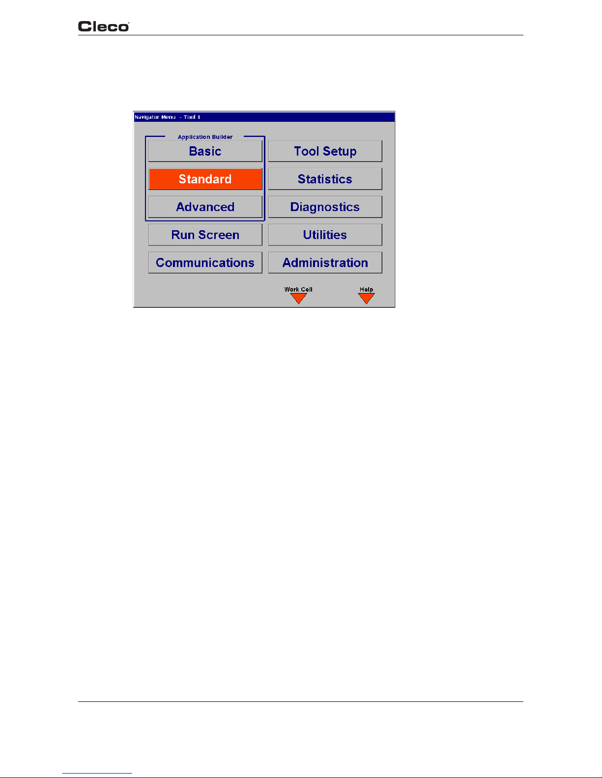
Fig. 3-1: Navigator Menu
nav.txtS
3.1.1 Basic Navigation Instructions
Each field in a screen is selectable with an orange highlight using the 4 arrow keys and Enter.
Upon entering a screen the top left most field is always highlighted. The Navigator key (ship's
wheel) will always return the user to the Navigator Menu. At the bottom of the screen 4 soft keys
are available. These functions will change from screen to screen. In some cases the screen label
will contain the (>>) character to indicate more functions are available when the key is pressed.
To edit a textbox the user can use 0-9 or the DEL keys. To exit the edit mode the user can press
the arrow keys to move the highlight or press the ESC key. The ESC key will return the original
value.
In order to describe the soft key functions the left soft key is referred to as F1, center left soft key
F2, center right soft key F3 and right soft key F4. They are located in the orange display border.
F4 is always functions as Help for that screen.
Applications are selectable 1-255. When entering an application number of 1 or 2 digits (1-99), a
cursor blinks in the edit box. The number is accepted when the <ENTER> key is pressed, or after
3 seconds. A 3 digit application number (100-255) is accepted as soon as the third character is
typed.
Stages are selectable 1-6.
3.1.2 Work Cell
To connect to a remote unit configured in the work cell, press the <F3> "Work Cell" button from
the Navigator menu. From the "Work Cell List" dialog box, press the <ENTER> key do display
the droplist of configured units. Use the up or down arrow keys to select the desired unit, then
press the <ENTER> key again. Press the down arrow key to highlight the "OK" button and press

22 PL12EN-1300 2008-03 en03d141.fm, 11.03.2008
Programming
3
the <ENTER> key again. The user interface switches control to the selected unit. When a remote
unit is selected the IP address, station name, and station number of that unit are displayed in the
title bar of all screens.
To return control to the local unit, return to the Navigator menu and use the above procedure, this
time selecting "Local TM Unit" in the Work Cell List dialog.
To add units to the Work Cell List, use the Work Cell screen in Communications.
3.1.3 Password Function
Passwords can be configured to operate in one of two modes: Read Protected or not Read Protected. Refer to Administration / Password for configuration details
Read Protected: A password is required when selecting a section from the Navigator menu. It is
only required to enter the password once. If the user exits a section with programmable data
(Basic, Standard, Advanced, Communications, Tool Setup) that has been changed, then only the
confirm entry in the password dialog is displayed.
Not Read Protected: No password is required when selecting a section from the Navigator menu.
If the user exits a section with programmable data (Basic, Standard, Advanced, Communica
tions, Tool Setup) that has been changed, then the password entry dialog will be displayed. If no
password is activated, then only the confirm entry in the password dialog is displayed. Once the
password has been entered, it must be entered each time an appropriate screen is exited.
3.1.4 Print Screen
A Print Screen function is available on all screens. In some cases a Print Screen soft key has
been added that will allow the bitmap to be saved to the floppy disk, disk, or print directly to a
printer (Laser, Inkjet). On screens that do not have this soft key, the user can reach this function
by pressing the "0" key. A dialog box allowing the user to assign a filename will be displayed.
Using the arrow keys, highlight the filename and enter up to 8 characters, then activate Accept to
save to the floppy.
3.1.5 Two Channel Features: General Description (2-Channel V2.xx.xx C2 only)
The user interface is identical to the single-channel configuration. On all screens, the data for the
currently selected tool is displayed. The current tool is selected by entering a 1 or 2 in the "Tool"
edit box. The Tool may be selected from the Run Screen, Basic Application Builder, Standard
Application Builder, or Statistics screens. On screens where there is no Tool edit box, the cur
rently selected tool is displayed in the blue title bar at the top of the screen. Both tools are always
operable regardless of which tool is currently selected by the user interface.
All editable parameters are set and saved individually for each tool, with the following exceptions:
• Language
• Date/Time
• Passwords
• Field Bus Parameters
• Torque Units
• Run Screen 2-Tool Display Configuration (Auto-select)
• Ethernet protocol, IP addresses and port number
• System Settings/General "Same for both tools" option
(See 3.4.7 Advanced Application Builder / System Settings, page 53)

en03d141.fm, 11.03.2008 PL12EN-1300 2008-03 23
Programming
3
The 2-channel model has the following limitations:
• Field Bus (DeviceNet/Profibus): When active, all inputs and outputs are only applicable to the
operation of Tool 1.
• The PFCS communications protocol uses a single Machine ID (MID) for both tools.
• The auto-select feature does not apply to the Oscilloscope screen.
3.1.6 Navigator Menu
Basic Application Builder
Basic Application Builder allows the user to graphically select and program a two-stage rundown
for Torque Control/Angle Monitor (Seq11+Seq30) or Angle Control/Torque Monitor
(Seq11+Seq50) for any of the 255 Applications. The user only enters Torque, Angle, and Speed
Setpoints in one screen. Other parameters such as timers, etc are automatically defaulted to predetermined values.
Standard Application Builder
Standard Application Builder allows the user to program up to a 6-stage rundown for any of the
255 Applications. Once the fastening sequences are selected for each stage, the associated
Torque, Angle, Speed, and Advanced parameters can be programmed.
Advanced Application Builder
Advanced Application Builder allows the user to View all Application setups at once, and perform
I/O Mapping. The Application Matrix shows an overview of Application and Stage programming
by displaying the selected Fastening Sequence for each stage. I/O Mapping lets the user select
from a list of functions and assign that function to a given input or output.
RUN Screen
The Run Screen button takes the user directly to the display for Torque, Angle, and Status Indicator Labels. The Oscilloscope function used for diagnosing torque traces is also located in the
Run Screen.
Communications
The Communications Setup allows the user to configure all communications for the Printer and
Serial Data Transmission. Appropriate communications settings for protocol, port, baud rate, etc
can be set in this screen.
Tool Setup
The Tool Setup displays the Tool Memory Data and allows the user to modify this information by
changing it directly or selecting from the Tool Library.
Statistics
Chronological History and associated statistics are viewable from this screen. Data can be
erased and printed as well.
Diagnostics
The System Diagnostics contains screens to determine if the system is functioning properly.
There are diagnostics for I/O, Arcnet, Tool and Tightening Module, Serial Communications, and
Transducer Calibration.

24 PL12EN-1300 2008-03 en03d141.fm, 11.03.2008
Programming
3
Utilities
Utilities contains functions for upgrading or changing the system software. From the Utilities
screen the user can update the TME application software, or install a new firmware version in the
Tightening Module.
3.1.7 Administration
From the Administration screen the user can load, save and configure system information.
Administration functions include loading and saving the system configuration to a diskette, set
ting date and time, setting password protection, and printing the system configuration, and
selecting the application software language
(English, German, Italian, Spanish, Czech, Portuguese, French, Polish, Dutch). From the Administration / Counter screen, the user may view, enable, disable, or reset any of the available
counters.
nav.txtE
3.2 Basic Application Builder
c00278en.bmp
Fig. 3-2: Torque Control / Angle Monitor

c00279en.bmp
en03d141.fm, 11.03.2008 PL12EN-1300 2008-03 25
Programming
3
Fig. 3-3: Angle Control / Torque Monitor
basic.txtS
The Basic Application Builder allows the user to select a typical two-stage rundown where the
first stage is a high speed rundown and the second stage is a lower speed rundown that controls
on either torque or angle.
Fastening Strategies Torque Control/Angle Monitoring (Sequence 11/Sequence 30) or Angle
Control/Torque Monitoring (Sequence 11/Sequence 50) are selectable from the dropdown listbox
in the upper right hand corner of the screen. Once a strategy is selected, the appropriate param
-
eters will be displayed for programming.
From the Basic Application Builder, the Auto Program feature is available by pressing the <F1>
soft key only when a tool is connected to the controller. The <F1> “Auto Program” button should
look disabled if there is no tool and <F1> should do nothing if there is no tool.
The <F1> soft key should be disabled if Angle Control/Torque Monitoring is selected. You can
input the Stage 2 target torque and select the units on this dialog. Pressing the <Cancel> button
exits the auto program screen without saving changes. Pressing the <OK> button causes the
auto calculations to be done and the results are displayed on the basic screen.
From the Basic Application Builder, the user can copy the parameters of an application to one or
more other applications by pressing the “Copy” <F3> soft key. From this dialog box, the user can
specify the source and target tool and application. When using “Copy” function from the Basic
Application Builder, all stages of the selected application are copied. Multiple target applications
may be specified by separating the application numbers with a period as shown.
Backoff using Reverse switch (Sequence 41 or Sequence 46)
The Backoff stage is automatically set to Sequence 46 for a tubenut tool and Sequence 41 for all
others. The automatic selection of a tube nut tool depends on a ‘T’ in the tool model number.
That means, if a ‘T’ appears in the model number a tube nut tool is expected. This fastening
sequence is selected when the tool runs in the reverse (untighten) direction. It is also used to
return a tubenut tool to the home position on every other trigger pull. The resolver integrated into
the nutrunner measures the angle during the untightening. The value is processed by the control

26 PL12EN-1300 2008-03 en03d141.fm, 11.03.2008
Programming
3
system. When the Turnoff angle is reached the nutrunner is shut off. For a tubenut tool, the Turnoff angle is programmed so that the attachment will always turn far enough to reach the home
position and stop based on the torque reaction against the pawl.
3.2.1 Basic Parameters for Torque Control / Angle Monitor
• Trigger Torque [Nm] - Torque to start collecting oscilloscope data.
• Turnoff Torque Stage 1 [Nm] - Torque to change from stage 1 to stage 2.
• Threshold Torque [Nm] - Torque to begin counting angle in stage 2.
• Torque Low Limit [Nm] - Minimum acceptable torque.
• Turnoff Torque Stage 2 [Nm] - Torque to turnoff the tool.
• Torque High Limit [Nm] - Maximum acceptable torque.
• Angle Low Limit [Deg] - Minimum acceptable angle.
• Angle High Limit [Deg] - Maximum acceptable angle.
3.2.2 Basic Parameters for Angle Control / Torque Monitor
• Turnoff Angle [Deg] - Angle to turnoff the tool.
• The rest of the Parameters are the same as Torque Control/Angle Monitor except Turnoff
Torque Stage 2 is eliminated.
Below are the acceptable ranges for each Parameter and its default value. For initial programming, the Parameters automatically use the default values.
3.2.3 Basic Application Builder Parameters
Parameter Name Range Typical
Fastening Strategy Torque Control/Angle Monitor
Angle Control/Torque Monitor
Torque Control/Angle Monitor
Trigger Torque [Nm] 0 to Tool Max 10% of Turnoff Torque
Turnoff Torque Stage 1 [Nm] 0 to Tool Max As appropriate
Threshold Torque [Nm] 0 to Tool Max 50% of Turnoff Torque
Torque Low Limit [Nm] -Tool Max* to Tool Max 90% of Turnoff Torque
Turnoff Torque Stage 2 [Nm] Low Limit to Tool Max As appropriate
Torque High Limit [Nm] Turnoff to 1.2 TQ-Cal. value 110% of Turnoff Torque
Angle Low Limit [Deg] 0 to 9999 90% of Turnoff Angle
Turnoff Angle [Deg] Low Limit to 9999 As appropriate
Angle High Limit Turnoff to 9999 110% of Turnoff Angle
Speed Stage 1 [RPM] 0 to Tool Max 80% of Tool Max
Speed Stage 2 [RPM] 0 to Tool Max 50
Backoff Speed 0 to Tool Max 50% of Tool Max
* Note: negative values may be entered by preceeding the value with two dots ".."
In the Basic Application Builder some parameters are not programmable and are also set to
default values. These values are located in the Standard Application Builder under Advanced
Parameters. However, if the parameters are changed using the Standard Application Builder,
then the Basic Application Builder does not reset them back to the default values.

en03d141.fm, 11.03.2008 PL12EN-1300 2008-03 27
Programming
3
3.2.4 Advanced Parameter Default Values
Parameter Name Stage 1 Stage 2
Start delay time [mS] 0 0
Start spike time [mS] 0 0
Max. Fastening time [mS] 10000 10000
End delay time [mS] 0 30
Torque Filter Factor 1 1
If NOK go to stage Stop Stop
Print None None
If an Application with more than two stages is required, or if a different Fastening Strategy has
previously been selected for the Application than described above, the Standard Application
Builder must be used.
3.2.5 Backoff using Reverse Switch (Sequence 41 or Sequence 46)
The Backoff stage is automatically set to Sequence 46 for a tubenut tool and Sequence 41 for all
others. The automatic selection of a tube nut tool depends on a ‘T’ in the tool model number.
That means, if a ‘T’ appears in the model number a tube nut tool is expected. This fastening
sequence is selected when the tool runs in the reverse (untighten) direction. It is also used to
return a tubenut tool to the home position on every other trigger pull. The resolver integrated into
the nutrunner measures the angle during the untightening. The value is processed by the control
system. When the Turnoff angle is reached the nutrunner is shut off. For a tubenut tool, the Turn
off angle is programmed so that the attachment will always turn far enough to reach the home
position and stop based on the torque reaction against the pawl.
3.2.6 Basic Application Builder / Auto Program
c00393en.bmp
Fig. 3-4: Basic Application Builder / Auto Program

28 PL12EN-1300 2008-03 en03d141.fm, 11.03.2008
Programming
3
From the Basic Application Builder, the Auto Program feature is available by pressing the <F1>
soft key only when a tool is connected to the controller and if the application is not already pro
grammed. The <F1> "Auto Program" button should look disabled if there is no tool or if the application is programmed or if Angle Control/Torque Monitoring is selected.
The Auto Program feature accepts the Stage 2 target torque and the torque units. Pressing the
cancel button exits the auto program screen without saving changes. Pressing the <OK> button
causes the auto calculations to be done and the results are displayed on the basic screen.
3.2.7 Basic Application Builder / Copy
c00362en.bmp
Fig. 3-5: Torque Control / Angle Monitor / Copy
From the Basic Application Builder, the user can copy the parameters of an application to one or
more other applications by pressing the Copy <F3> soft key. From this dialog box, the user can
specify the source and target tool and application. When using Copy function from the Basic
Application Builder, all stages of the selected application are copied. Multiple target applications
may be specified by separating the application numbers with a period as shown.
basic.txtE

en03d141.fm, 11.03.2008 PL12EN-1300 2008-03 29
Programming
3
3.3 Standard Application Builder
3.3.1 Standard Application Builder / View Stages
c00280en.bmp
Fig. 3-6: View Stages
viewstag.txtS
From View Stages, Stages 1-6 and a Backoff Stage are programmable for a given tool and application.
When the tool is started, each Stage having a programmed Fastening Sequence will be run in
succession based on the results from the previous stage. The Backoff Stage is used when the
tool is run in the reverse or untighten direction.
When the Counter Clockwise box is checked, each stage is run with the tool tightening in a
counter-clockwise direction. Sequence 41 (angle controlled backout) and the Backoff Stage are
run in the clockwise direction.
WARNING: When the Counter-Clockwise box is checked, the normal direction of rotation
is opposite from what is indicated by the label of the Reverse switch on the tool.
If a sequence has not been selected for a stage, then N/A is displayed for that stage. Otherwise
the Sequence number, description and icon are displayed. Sequences can be selected using the
Select Seq <F1> soft key. This key is only valid when stages 1-6 are highlighted. The Fastening
Sequence for the Backoff Stage is selected automatically.
The parameters for any stage can be programmed using the Parameters <F3> soft key. This key
is only valid when a Sequence has been selected for a given Stage.

30 PL12EN-1300 2008-03 en03d141.fm, 11.03.2008
Programming
3
3.3.2 Standard Application Builder / View Stages / Copy
c00366en.bmp
Fig. 3-7: View Stages / Copy
From the Standard Application Builder, the user can copy the parameters of an application or
stage to one or more other applications or stages by pressing the Copy <F2> soft key. From this
dialog box, the user can specify the source and target tool, application, and one or all stages. A
single stage can be copied to multiple applications and/or stages. Multiple target applications and
stages may be specified by separating the numbers with a period.
viewstag.txtE

en03d141.fm, 11.03.2008 PL12EN-1300 2008-03 31
Programming
3
3.3.3 Standard Application Builder / Select Sequence
c00281en.bmp
Fig. 3-8: Select Sequence
selectse.txtS
Fastening Sequences are selectable for a given Tool, Application and Stage by using the Control
and Monitor check boxes or selecting a Fastening Sequence directly from the drop down listbox.
The following Fastening Sequences or Fastening Strategies are available:
Sequence 41 or Sequence 46 Backoff using Reverse switch/Relax
Sequence 11 High Speed Rundown
Sequence 30 Torque Control/Angle Monitor
Sequence 50 Angle Control/Torque Monitor
Sequence 41 Angle Controlled Backoff
When a Sequence is selected the Control and Monitor check boxes and Fastening Sequence
listbox will both display the appropriate settings for the selected Sequence. An icon portraying
the selected Sequence is also displayed in the bottom right-hand corner.
The following table shows a matrix of the Control and Monitor schemes for each Sequence:
Sequence 11 Sequence 30 Sequence 50 Sequence 41
Control
Torque Control X X
Angle Control X
Angle Control Reverse X
Monitor
Torque Monitor X X
Angle Monitor X X X
The Parameters <F3> soft key allows the user to program all associated control parameters for
the selected Sequence. It is only valid when a Sequence has been selected.

32 PL12EN-1300 2008-03 en03d141.fm, 11.03.2008
Programming
3
The following is a detailed description of each Fastening Sequence:
Sequence 11
High Speed Rundown
This tightening method is generally used as a fast pre-tightening stage. The torque transducer
integrated into the nutrunner measures the torque during the tightening. The value is processed
by the control system. When the defined Turnoff Torque is reached the nutrunner is shut off.
Thereafter the peak torque is measured during a dwell time and is then processed as the tighten
ing torque of the bolt in the control system. This value is displayed on the Run Screen and can be
output to a printer or transmitted to other system components by data communication. When the
trigger torque is reached the torque curve is recorded and can be viewed and evaluated using
the oscilloscope function.
Sequence 30
Torque Control with Torque and Angle Monitoring
This tightening stage is normally preceded by a fast pre-tightening stage. The transducer integrated into the nutrunner measures the torque and the resolver measures the angle during the
tightening. The values are processed by the control system. When the threshold torque is
reached the angle count starts. When the Turnoff Torque is reached the nutrunner is shut off.
Thereafter the peak torque is measured during a dwell time and is then processed as the tighten
ing torque of the bolt together with the evaluation of the rundown in the control system. This
value is displayed on the Run Screen and can be output to a printer or transmitted to other sys
tem components by data communication. When the trigger torque is reached the torque curve is
recorded and can be viewed and evaluated using the oscilloscope function.
Sequence 50
Angle Controlled Tightening with Angle and Torque Monitoring
This tightening sequence is generally preceded by a fast pre-tightening cycle. The transducer
integrated into the nutrunner measures the torque and the resolver measures the angle during
the rundown. The values are processed by the control system. When the Turnoff angle is
reached the nutrunner is shut off. Thereafter the final angle and the peak torque are measured
during a dwell time, and these tightening values for the bolt are then processed together with the
evaluation of the rundown in the control system. These values are displayed on the Run Screen
and can be output to a printer or transmitted to other system components by data communica
tion. When the trigger torque is reached the torque curve is recorded and can be viewed and
evaluated using the oscilloscope function.
Sequence 41
Angle Controlled Back-off with Angle Monitoring
This fastening sequence is generally used to loosen a bolt a specified number of degrees. The
resolver integrated into the nutrunner measures the angle during the untightening. The value is
processed by the control system. When the Turnoff angle is reached the nutrunner is shut off.
Thereafter the final angle is measured during a dwell time and is then processed as the back-off
angle of the bolt together with the evaluation of the untightening in the control system. This value
is displayed on the Run Screen and can be output to a printer or transmitted to other system
components by data communication. In this stage the oscilloscope function is not supported.
Sequence 41 or Sequence 46
Backoff using Reverse switch/Relax
The Backoff stage is automatically set to Sequence 46 for a tubenut tool and Sequence 41 for all
others. The automatic selection of a tube nut tool depends on a 'T' in the tool model number. That
means, if a 'T' appears in the model number a tube nut tool is expected. This fastening sequence
is selected when the tool is run in the reverse or untighten direction. It is also used to return a

en03d141.fm, 11.03.2008 PL12EN-1300 2008-03 33
Programming
3
tubenut tool to the home position on every other trigger pull. The resolver integrated into the
nutrunner measures the angle during the untightening. The value is processed by the control
system. When the Turnoff angle is reached the nutrunner is shut off. For a tubenut tool, the Turn
off angle is programmed so that the attachment will always turn far enough to reach the home
position and stop based on the torque reaction against the pawl.
selectse.txtE
3.3.4 Standard Application Builder / Parameters
c00282en.bmp
Fig. 3-9: Parameters
paramete.txtS
Parameters are programmable for a given Tool, Application and Stage based on the selected
Fastening Sequence and only the appropriate parameters are displayed for the selected Fasten
ing Sequence.
The Next Stage <F2> key will increment to the next stage until it reaches the last stage having a
selected Sequence. It will then rollover to the first stage. In order to add a stage without a
selected Sequence the user must highlight the stage field and enter a number 1-6.
The following is a detailed description of each Fastening Sequence and associated Parameters:
Sequence 11
High Speed Rundown
This tightening method is generally used as a fast pre-tightening stage. The torque transducer
integrated into the nutrunner measures the torque during the tightening. The value is processed
by the control system. When the defined Turnoff Torque is reached the nutrunner is shut off.
Thereafter the peak torque is measured during a dwell time and is then processed as the tighten
ing torque of the bolt in the control system. This value is displayed on the Run Screen and can be
output to a printer or transmitted to other system components by data communication. When the
trigger torque is reached the torque curve is recorded and can be viewed and evaluated using
the oscilloscope function.

34 PL12EN-1300 2008-03 en03d141.fm, 11.03.2008
Programming
3
The following parameters are programmable from the Standard Application Builder:
• Fastening Sequence = 11
• Trigger Torque (Nm) = trigger torque, beginning of measurement for the graphic display.
• Turnoff Torque (Nm) = turnoff torque for the pre-tightening stage.
• Speed = max speed of the nutrunner during the pre-tightening stage.
Parameter Name Range Typical
Fastening Strategy Sequence 11 High Speed Rundown
Trigger Torque [Nm] 0 to Tool Max 10% of Turnoff Torque
Turnoff Torque [Nm] Trigger to Tool Max As appropriate
Speed Stage 1 [RPM] 0 to Tool Max 80% of Tool Max
Sequence 30
Torque Control with Torque and Angle Monitoring
This tightening stage is normally preceded by a fast pre-tightening stage. The transducer integrated into the nutrunner measures the torque and the resolver measures the angle during the
tightening. The values are processed by the control system. When the threshold torque is
reached the angle count starts. When the Turnoff Torque is reached the nutrunner is shut off.
Thereafter the peak torque is measured during a dwell time and is then processed as the tighten
ing torque of the bolt together with the evaluation of the rundown in the control system. This
value is displayed on the Run Screen and can be output to a printer or transmitted to other sys
tem components by data communication. When the trigger torque is reached the torque curve is
recorded and can be viewed and evaluated using the oscilloscope function.
The following parameters are programmable in the Standard Application Builder:
• Sequence input value = 30
• Trigger Torque (Nm) = trigger torque, beginning of measurement for the graphic display.
• Threshold Torque (Nm) = threshold torque, beginning of angle counting
• Turnoff Torque (Nm) = shut-off torque for the stage.
• Torque High Limit (Nm) = max torque, high limit for torque reached.
• Torque Low Limit (Nm) = min torque, low limit for torque reached.
• Angle High Limit (deg) = maximum angle, high limit for angle reached. The nutrunner will stop
if this value is exceeded
• Angle Low Limit (deg) = minimum angle, low limit for angle reached.
• Speed = max speed of the nutrunner during the tightening stage.
Parameter Name Range Typical
Fastening Strategy Sequence 30 Torque Control/
Angle Monitor
Trigger Torque [Nm] 0 to Tool Max 10% of Turnoff Torque
Threshold Torque [Nm] 0 to Tool Max 50% of Turnoff Torque
Torque Low Limit [Nm] -Tool Max* to Tool Max 90% of Turnoff Torque
Turnoff Torque [Nm] Low Limit to Tool Max As appropriate
Torque High Limit [Nm] Turnoff to 9999 110% of Turnoff Torque
Angle Low Limit [Deg] 0 to 9999 70% of Final Angle
Angle High Limit Low Limit to 9999 130% of Final Angle
Speed [RPM] 0 to Tool Max 50
* Note: negative values may be entered by preceeding the value with two dots ".."

en03d141.fm, 11.03.2008 PL12EN-1300 2008-03 35
Programming
3
Sequence 50
Angle Controlled Tightening with Angle and Torque Monitoring
This tightening sequence is generally preceded by a fast pre-tightening cycle. The transducer
integrated into the nutrunner measures the torque and the resolver measures the angle during
the rundown. The values are processed by the control system. When the Turnoff angle is
reached the nutrunner is shut off. Thereafter the final angle and the peak torque are measured
during a dwell time, and these tightening values for the bolt are then processed together with the
evaluation of the rundown in the control system. These values are displayed on the Run Screen
and can be output to a printer or transmitted to other system components by data communica
tion. When the trigger torque is reached the torque curve is recorded and can be viewed and
evaluated using the oscilloscope function.
The following parameters are programmable in the Standard Application Builder:
• Sequence input value = 50
• Trigger Torque (Nm) = trigger torque, beginning of measurement for the graphic display
• Threshold Torque (Nm) = threshold torque, beginning of angle counting
• Turnoff Angle (deg) = shut-off angle for the stage
• Angle High Limit (deg) = maximum angle, high limit for angle reached
• Angle Low Limit (deg) = minimum angle, low limit for angle reached
• Torque High Limit (Nm) = max torque, high limit for torque reached and safety shut-off
• Torque Low Limit (Nm) = min torque, low limit for torque reached
• Speed = max speed of the nutrunner during the tightening stage
Parameter Name Range Typical
Fastening Strategy Sequence 50 Angle Control/
Torque Monitor
Trigger Torque [Nm] 0 to Tool Max 10% of Turnoff Torque
Threshold Torque [Nm] 0 to Tool Max As appropriate
Torque Low Limit [Nm] -Tool Max* to Tool Max 70% of Final Torque
Torque High Limit [Nm] Low Limit to Tool Max. 130% of Final Torque
Angle Low Limit [Deg] 0 to 9999 90% of Turnoff Angle
Turnoff Angle [Deg] Low Limit to 9999 As appropriate
Angle High Limit Turnoff angle to 9999 110% of Turnoff Angle
Speed Stage [RPM] 0 to Tool Max 50
* Note: negative values may be entered by preceeding the value with two dots ".."

36 PL12EN-1300 2008-03 en03d141.fm, 11.03.2008
Programming
3
Sequence 41
Angle Controlled Back-off with Angle Monitoring
This fastening sequence is generally used to loosen a bolt a specified number of degrees. The
resolver integrated into the nutrunner measures the angle during the untightening. The value is
processed by the control system. When the Turnoff angle is reached the nutrunner is shut off.
Thereafter the final angle is measured during a dwell time and is then processed as the back-off
angle of the bolt together with the evaluation of the untightening in the control system. This value
is displayed on the Run Screen and can be output to a printer or transmitted to other system
components by data communication. In this stage the oscilloscope function is not supported.
The following parameters are programmable in the Standard Application Builder:
• Sequence input value = 41
• Turnoff Angle (deg) = shut-off angle, back-off angle
• Angle High Limit (deg) = maximum angle, high limit for angle reached.
• Angle Low Limit (deg) = minimum angle, low limit for angle reached.
• Speed = max speed of the nutrunner during the back-off stage.
Parameter Name Range Typical
Fastening Strategy Sequence 41 Angle Control in Reverse
Angle Low Limit [Deg] 0 to 9999 90% of Turnoff Angle
Turnoff Angle [Deg] Low Limit to 9999 As appropriate
Angle High Limit Turnoff angle to 9999 110% of Turnoff Torque
Speed [RPM] 0 to Tool Max 80% of Tool Max
Backoff Using Reverse Switch (Sequence 41 or Sequence 46)
The Backoff stage is automatically set to Sequence 46 for a tubenut tool and Sequence 41 for all
others. The automatic selection of a tube nut tool depends on a "T" in the tool model number.
That means, if a "T" appears in the model number a tube nut tool is expected. This fastening
sequence is selected when the tool is run in the reverse or untighten direction. It is also automat
ically used to return a tubenut tool to the home position on every other trigger pull. The resolver
integrated into the nutrunner measures the angle during the untightening. The measured angle
value is processed by the control system. When the Turnoff angle is reached the nutrunner is
shut off. For a tubenut tool, the Turnoff angle is programmed so that the attachment will always
turn far enough to reach the home position and stop based on the torque reaction against the
pawl.
The following parameters are programmable in the Standard Application Builder:
• Speed [rpm] = Max speed of the nutrunner during the backoff stage
Parameter Name Range Default
Speed [RPM] 0 to Tool Max 500 or 30% of Tool Max
(tubenut)

en03d141.fm, 11.03.2008 PL12EN-1300 2008-03 37
Programming
3
The backoff parameters that are not displayed are set to values as in the table below.
Parameter Name Sequence 41 Sequence 46
Start delay time [mS] 0 0
Start spike time [mS] 0 0
Max. Fastening time [mS] 10000 10000
End delay time [mS] 30 30
Torque Filter Factor 1 1
Tor q u e Ta r ge t --- 3,5% of Tool max. Torque
Torque High Limit --- 10% of Tool max. Torque
Angle Low Limit 0 0
Angle Target 9999 370
Angle High Limit 9999 380
For at tube nut tool the maximum speed for backoff is 30% of Tool Max Speed. It is not possible
to enter a higher value.
Relax
This sequence is generally used at the end of a rundown to prevent mechanical locking of the
tool without loosening the joint.
The relax parameters are set to values as in the table below. These parameters cannot be programmed.
Parameter Name Value
Fastening strategy Sequence 46
Start delay time [ms] 0
Start spike time [ms] 0
Max. fastening time [ms] 3000
End delay time [ms] 0
Torque filter factor Used from preceding stage
Tor q u e t a r g e t 1/6 of Torque low limit from preceding stage
Torque high limit 1/3 of Torque low limit from preceding stage
Angle low limit 0
Angle target 3
Angle high limit 6
Speed stage [RPM] Used from preceding stage
The results are not displayed on the Run Screen unless the relax stage was NOK.
paramete.txtE

38 PL12EN-1300 2008-03 en03d141.fm, 11.03.2008
Programming
3
3.3.5 Standard Application Builder / Advanced Parameters
c00283en.bmp
Fig. 3-10: Advanced Parameters
advparam.txtS
The user can enter the Advanced Parameters using the Advanced <F3> soft key from the
Parameter screen. These parameters are identical regardless of the selected Fastening
Sequence.
The Next Stage <F2> key will increment to the next stage until it reaches the last stage with a
selected Sequence. It will then rollover to the first stage. In order to add a stage without a
selected Sequence the user must highlight the stage field and enter a number 1-6.
Timers
Start delay time [mS] time delay before the stage will start
Start spike time [mS] time delay for the control system to start measuring torque after the stage
starts
Max. Fastening time [mS] max time for the tool to run during the stage.
End delay time [mS] time delay from tool turn off until shut-off of measured value recording.
Other
Torque Filter Factor used for torque averaging

en03d141.fm, 11.03.2008 PL12EN-1300 2008-03 39
Programming
3
Speed Ramp-up, Beginning of Stage
Ramp-up time [ms]: Time to accelerate to tool max speed.
Speed Ramp-down, End of Stage
Deactivate Ramp-down: Allows the user to deactivate the ramp-down.
Begin Ramp-down [%]: Percentage of turn off torque (seq 11, 30) or high limit torque (seq 50),
where speed ramp-down begins.
Use Default for Target
Speed:
Default value for target speed is used. The default value depends on
parameter of the next stage. Refer to the programming manual for more
information.
Target Speed [RPM]: Target speed after ramp-down at turn off. From beginning of ramp down,
speed is reduced in 30 steps to target speed.
Flex-Stop, After Turn-off
Deactivate Flex-Stop: Allows the user to deactivate the flex-stop.
Flex-Stop [%]: Percentage of duration of flex-stop. The higher the percentage the longer it
takes to relieve torque after shut-off. The absolute time depends on the run
-
down parameter and the joint.
Max Flex-Time [ms]: Max time for flex-stop to relieve torque after shut off
Advanced Parameters Default Range of Values
Start delay time [mS] 0 0 - 60000
Start spike time [mS] 0 0 - 999
Max. Fastening time [mS] 10000 1 - 60000
End delay time [mS] 30 0 - 999
Torque Filter Factor 1 1, 2, 4, 8, 16, 32
Ramp-up time [ms] 1000 100 - 2000
Begin Ramp-down [%] 90 1 - 100
Target Speed [RPM] (*) 1 - speed of stage
Flex-Stop [%] 50 10 - 100
Max Flex-Time [ms] 1000 1 - 2000
.
(*) The default value depends on parameter of the next stage. Refer to manual for more information.
advparam.txtE

40 PL12EN-1300 2008-03 en03d141.fm, 11.03.2008
Programming
3
3.4 Advanced
3.4.1 Advanced Application Builder / Application Matrix
c00284en.bmp
Fig. 3-11: Application Matrix
appmatri.txtS
The Application Matrix is a display matrix of 255 Applications vs. 6 Stages showing the selected
Sequence number for each stage. It gives the user an overview of controller programming in a
single screen. The arrow following the sequence number for a stage indicates the direction of
rotation (> for clockwise; < for counter-clockwise).
appmatri.txtE

en03d141.fm, 11.03.2008 PL12EN-1300 2008-03 41
Programming
3
3.4.2 Advanced Application Builder / Inputs
c00285en.bmp
Fig. 3-12: Inputs
Tool
Start
Tool Stop
in Final
Stage
Tool
Start
Inp uts
I0. Application Select 0
I1. Application Select 1
I2. Application Select 2
I3. Tool Start
I4. Re ject R eleas e
I5. To ol Re vers e
I6. Tool Enable
With Linking:
I7. Reset Linking /
Synchronization In
With Tool Synchronization:
I7. Reset Linking /
Synchronization In
Start
Stage2
c00288en.bmp
Fig. 3-13: Input Timing Diagram
inputs.txtS

42 PL12EN-1300 2008-03 en03d141.fm, 11.03.2008
Programming
3
Eight optically isolated, +24 V inputs are available at the Phoenix input connector under the right
side door and are defined as follows:
PIN 1 +24 VDC
PIN 2 Input 0
PIN 3 Input 1
PIN 4 Input 2
PIN 5 Input 3
PIN 6 Input 4
PIN 7 Input 5
Pin 8 Input 6
PIN 9 Input 7
PIN 10 Input Common
Pin 11 Signal Ground
Pin 12 Spare
Each of the physical inputs 0 - 7 can be programmed to have one of the following definitions:
Not Used Unused
Too l E nable When active, allows the tool to run in conjunction with Tool Start
Too l Sta r t Starts the tool. Works in parallel with the start switch on the tool.
Too l R everse When active, causes the tool to run in the counter-clockwise direc-
tion using the Backoff strategy. Works in parallel with the reverse
actuator on the tool
Too l R eady Prepares the controller for a new rundown. When active, the previ-
ous outputs are cleared, and the yellow LEDs flash
Appl. Select 0 Application Selects 0-7 are used to select Applications 1-255
using a binary count of 0-254 where Appl. Select 0 is the
least significant bit. This feature overrides application
changes from the keypad. When Linking is activated, the
Tightening Group is selected with these inputs.
Appl. Select 1
Appl. Select 2
Appl. Select 3
Appl. Select 4
Appl. Select 5
Appl. Select 6
Appl. Select 7
Synchronization Input If enabled from Advanced / System Settings, the tool is prevented
from continuing to the next stage until this input is active
Reset Linking When active, Linking (batch counting) is reset to position one
Reject Release Used when Reject Release is enabled from System Settings, and
the Release Method is "Release Input Toggle". When the tool is
disabled due to the reject limit being reached, it is re-enabled after
this input is toggled

Socket Tray Enable Socket Tray Enable is used along with Socket Tray Sel 0-2 to indi-
cate to the worker which socket to use.
Socket Tray Sel 0
Socket Tray Sel 1
Socket Tray Sel 2
Acknowledge When this signal is ON, the "results" output signals should be
cleared and the tool cannot be started; however, the tool LEDs
should still indicate the status of the previous rundown until
cleared by another tool start or the tool ready signal.
en03d141.fm, 11.03.2008 PL12EN-1300 2008-03 43
Programming
3
All inputs are active high. They are referenced to an isolated Input Common (pin 10). When using
the internal +24 V (pin 1) to activate these inputs, you must connect Input Common (pin
10) and
GND (pin 11). For hardware pin location please see
page 19.
Note:
When active, the Fieldbus has the priority. Refer to help page for Advanced / Fieldbus.
inputs.txtE
3.4.3 Advanced Application Builder / Outputs
c00286en.bmp
Fig. 3-14: Outputs

Tool
Start
Tool Stop
in F inal
Stage
Tool
Start
Outputs
O0. Cycle OK
O1. Cycle NOK
O2. Torque High
O3. Torque Low
O4. Linking OK
O5. Linking NOK
O6. Cycle Complete
With Linking:
O7 . Linkin g C om plete /
Synchronization Out
With Tool Synchronization :
O7 . Linkin g C om plete /
Synchronization Out
As appropriate
As appropriate
As appropriate
As appropriate
As appropriate
As appropriate
As appropriate
End
Stage1
Start
Stage2
c00287en.bmp
44 PL12EN-1300 2008-03 en03d141.fm, 11.03.2008
Programming
3
Fig. 3-15: Output Timing Diagram
outputs.txtS
Eight relay outputs are available at the Phoenix output connector under the right side door and
are defined as follows:
PIN 1 +24 VDC
PIN 2 Output Common
PIN 3 Output 0
PIN 4 Output 1
PIN 5 Output 2
PIN 6 Output 3
PIN 7 Output 4
PIN 8 Output 5
PIN 9 Output 6
PIN 10 Output 7
PIN 11 Signal Ground
PIN 12 Spare
Each of the physical outputs 0-7 can be programmed to have one of the following definitions:
Not Used Unused
OK Active if Torque / Angle / Yield are within programmed limits

en03d141.fm, 11.03.2008 PL12EN-1300 2008-03 45
Programming
3
All relay outputs are active high. One side of all of the relay contacts is tied to a common point
called Output Common (pin 2). When using the internal +24 V (pin 1) as a source for these out
puts, you must connect Output Common (pin 2) and +24 V (pin 1). The outputs will then be referenced to GND (pin 11). For hardware pin location please see page 19.
Note:
When active, the Fieldbus inputs have priority. Refer to help page for Advanced / Fieldbus.
outputs.txtE
NOK Active if Torque / Angle / Yield are outside limits or some
other error has occurred
Torque Low Active if Peak Torque < Torque Low Limit
Torque High Active of Peak Torque > Torque High Limit
Angle Low Active if Angle < Angle Low Limit
Angle High Active of Angle > Angle High Limit
Torque OK Active if Peak Torque is within limits
Angle OK Active if Angle is within limits
Tool Running Active when the tool is running
Cycle Complete Active when a rundown has ended in the last stage
Linking Complete Active when rundowns of all positions of the selected batch
group are complete
Linking OK Active if all positions of Linking were OK
Linking NOK Active if one or more positions of Linking were NOK
Confirm App. Sel 0 Confirm application Selects 0-7 are used to indicate the
currently selected applications 1-255 using a binary count
of 0-254 where Appl. Select 0 is the least significant bit
Confirm App. Sel 1
Confirm App. Sel 2
Confirm App. Sel 3
Confirm App. Sel 4
Confirm App. Sel 5
Confirm App. Sel 6
Confirm App. Sel 7
Sync Output If enabled from Advanced / System Settings it is active at
the end of each stage to allow for synchronization with
other controllers
Tool In Reverse Indicates that a tool reverse input or actuator is set
Socket Tray Enable Pass-through of Socket Tray Enable input signal
Socket Tray Sel 0 Pass-through of Socket Tray select 0-2 input signals
Socket Tray Sel 1
Socket Tray Sel 2
Fault (Active Low) Indicates the servo module has detected an error (trans-
ducer, resolver etc)

46 PL12EN-1300 2008-03 en03d141.fm, 11.03.2008
Programming
3
3.4.4 Advanced Application Builder / Fieldbus
c00400en.bmp
Fig. 3-16: FieldBus
fieldbus.txtS
From the FieldBus Screen the user is allowed to choose from four options for fieldbus connections: None, DeviceNet, Profibus, or Ethernet/IP.
For selection of DeviceNet or Profibus additional hardware is required.

en03d141.fm, 11.03.2008 PL12EN-1300 2008-03 47
Programming
3
Field Bus Configuration
Node Address Defines the address of the TME controller. DeviceNet (1-63),
Profibus (2-125), Ethernet/IP uses the controller IP address
configured in Communications / Data Transmission.
Baud Rate Defines the rate at which information is sent/received from the
TME controller. For DeviceNet three choices are available:
500KBits, 250 KBits, or 125 KBits. The rate should be set to
match the fieldbus system available. For Profibus and Ether
net/IP, this option is not available. The Baud Rate is automatically set to the master settings.
Part ID A checked box enables the Part ID function.
Disable on disconnect A checked box that disables further rundowns and displays a
"Check Cable" Message on Run Screen as long as the field
-
bus doesn't work.
Format Determines how the 32-bit Part ID is converted into readable
characters. When "Decimal" is selected, the resulting Part ID
is 10 characters in length. When "Hexadecimal" is selected,
the resulting Part ID is 8 characters in length.
Tool 2 Control A checked box enables an alternate format for word 1 byte 0 of
the fieldbus outputs that replaces the standard Torque/Angle
results outputs with Cycle OK, Cycle NOK, and "yellow light"
outputs that originate from tool 2.
Dwell Time This is the number of milliseconds that each fieldbus output bit
will stay on or off immediately after a state change. The stan
-
dard range is 50 to 999 milliseconds.
Enable I/O Configuration
This section allows the user to control the information sent/received in the data stream. Inputs
and Outputs can be individually enabled.
Inputs
Appl. Select (1-8) Allows the fieldbus to control the Application selected from 1
to 8
Reset Linking Allows the fieldbus to reset the linking to the first position
Remote Tool Start Allows the fieldbus to start the tool
Remote Tool Reverse Allows the fieldbus to control the rotation direction
Too l R eady Allows the fieldbus to blink the yellow LED on the tool
Too l E nable Allows the fieldbus to enable/disable the tool
Appl. Select (9-255) Allows the fieldbus to control the Application selected 1 to
255. This can only be enabled if Appl. Select (1-8) is set
Socket Tray Lamp
Select (1-8)
Allows the fieldbus to control the Socket Tray Lamp Select,
and enables the "Socket Tray Lamps Enable" input.
Outputs
Linking Outputs Output data will include linking OK, NOK, and Complete
Appl. Select (1-8) Output data will include current Application selection 1-8

48 PL12EN-1300 2008-03 en03d141.fm, 11.03.2008
Programming
3
Tool Enable from Socket
Tray
Output data will include the tool enable signal from socket
tray
Tool Running Output data will indicate when tool is in a rundown cycle
Too l R everse Output data will indicate when tool is in reverse
Cycle Complete Output data will indicate when rundown cycle is complete
Tool Ready Input PassThrough
Output data will include the tool ready signal from the input
Green Tool Light
(Cycle OK)
Output data will indicate when cycle is within programmed
limits
Cycle NOK Output data will indicate when cycle is outside of programmed
limits
Yellow Tool Light Output data will indicate when cycle met the yellow light con-
ditions
Torque/Angle Results Output data will indicate results for the torque and angle spe-
cifically
Appl. Select (9-255) Output data will include current Application selection 1 to 255.
This can only be enabled if Application Select (1-8) is set
Socket Tray Appl.
Select (1-8)
Output data will indicate the socket tray appl. select
Fault Indicates the servo module has detected an error (transducer,
resolver etc)

en03d141.fm, 11.03.2008 PL12EN-1300 2008-03 49
Programming
3
Signal Descriptions
Inputs
If DeviceNet configuration is selected, the input packet is 4 Words long (8 bytes) including Part ID
Number (4 bytes) if enabled, or 2 words long (4 bytes) if Part ID is not enabled.
If Profibus configuration is selected, the input packet is 4 words long (8 bytes).
WORD 0 BYTE 0 BIT 0-3: Spare
BIT 4-6: Application/Link. Select Code 1-8(Bit 4=LSB)
BIT 7: Reset Linking
BYTE 1: BIT 0: Remote Tool Start
BIT1: Remote Tool Reverse
BIT 2: Tool Ready (Flashing Yellow Light)
BIT 3: Tool Enable
BIT 4: Socket Tray Lamps Enable
BIT 5: Socket Tray Lamps Appl. Sel. 0
BIT 6: Socket Tray Lamps Appl. Sel. 1
BIT 7: Socket Tray Lamps Appl. Sel. 2
WORD 1 BYTE 0 BIT 0-4: Application/Link. Select Code 9-255 (Bit 0=LSB)
BIT 5-7: Spare
BYTE 1 ALL: Spare
WORD 2 BYTE 0 ALL: Part ID
BYTE 1 ALL: Part ID
WORD 3 BYTE 0 ALL: Part ID
BYTE 1 ALL: Part ID
Example of Part ID (BCD - HEX Format)
WORD 3 BYTE 1 00000000 - 00
BYTE 0 00000010 - 02
WORD 2 BYTE 1 11111111 - F F
BYTE 0 00000001 - 01
The HEX-Format (0002FF01) will be displayed on the Run Screen, Chrono History, and Printout.

50 PL12EN-1300 2008-03 en03d141.fm, 11.03.2008
Programming
3
Outputs
The output packet will be 2 Words long (4 bytes). When Ethernet/IP is the selected field bus, and
the "Torque / Angle Values" box is checked, the output packet is 5 words (10 bytes). The status of
all fieldbus outputs is viewable from a diagnostics screen on the TME. All outputs are updated
continuously.
WORD 0 BYTE 0 BIT 0: Spare
BIT 1: Linking OK
BIT 2: Linking NOK
BIT 3: Linking Complete
BIT 4-6: Application/Link Select Code 1-8 (Mirror)
BIT 7: Tool-Enable from Socket Tray
BYTE 1 BIT 0: To o l I n- C y c l e
BIT 1: Tool Reverse Switch
BIT 2: Fault
BIT 3: Cycle Complete
BIT 4: Tool Ready pass-through from Input
BIT 5: Socket Tray Application Select
BIT 6: Socket Tray Application Select
BIT 7: Socket Tray Application Select
WORD 1 BYTE 0 BIT 0: Green Tool Light (Cycle OK)
BIT 1: Cycle NOK
BIT 2: Yellow Tool Light
BIT 3: Torque Low
BIT 4: Torque High
BIT 5: Angle Low
BIT 6: Angle High
BIT 7: Spare
BYTE 1 BIT 0-4: Application/Link Select Code 9-255 (Mirror)
BIT 5-7: Spare
WORD 2 BYTE 0 ALL: To rq ue
BYTE 1 ALL: To r qu e
WORD 3 BYTE 0 ALL: To rq ue
BYTE 1 ALL: To r qu e
WORD 4 BYTE 0 ALL: Angle
BYTE 1 ALL: Angle
fieldbus.txtS

en03d141.fm, 11.03.2008 PL12EN-1300 2008-03 51
Programming
3
3.4.5 Advanced / Linking
c00315en.bmp
Fig. 3-17: Linking
linking.txtS
Linking allows the user to automatically change from application to application for a predefined
number of positions (up to 96). Each application is run when the start switch on the tool is acti
vated in the order specified by its position. Upon completion of the cycle, the application will then
automatically change to the next position. Up to eight different linking strategies called Tightening
Groups can be programmed and are remotely selectable from the Application Inputs (0-2). This
feature can also be used for Batch Counting by entering the same application in the desired
number of positions.
To setup a linking strategy, a Tightening Group 1-8 should be selected and given a name. This
will designate which linking strategy is being used. The user can also program if the linking strat
egy should reset to position 1 after an NOK or set the number of times a fastener can be retightened after an NOK before advancing to the next position.
To configure linking, an Application 1-255 must be associated with a position in the linking strategy. To do this, the user must enter App (1-255), and can also provide a Fastener ID and Position
Name. Pressing Add <F1> will place the selected application in the user-specified position of the
linking strategy. Pressing Delete <F2> will remove the user-specified position from the linking
strategy. Once Linking is enabled, the controller will automatically run from position 1 to the last
programmed position. Note that the tool start switch or remote start input will have to be toggled
between positions. The Tightening Group and Position will also be displayed on the Run Screen.
The following inputs and outputs will also be active when Linking is enabled: Linking OK, Linking
NOK, Linking Complete, and Reset Linking. Please refer to the Inputs and Outputs section for
more information on these signals.
linking.txtE

52 PL12EN-1300 2008-03 en03d141.fm, 11.03.2008
Programming
3
3.4.6 Advanced Application Builder / Signals
c00416en.bmp
Fig. 3-18: Signals
signlset.txtS
From the Signals screen the user can configure set conditions that control the activation of signals.
The fault signal for a tool may be activated by a servo warning event, total cycles exceeding a
desired number, cycles since service exceeding a desired number, or any combination of these
three choices. The fault signal becomes active when any of the selected conditions are satisfied.
These settings are stored together with the system settings.
signlset.txtE

en03d141.fm, 11.03.2008 PL12EN-1300 2008-03 53
Programming
3
3.4.7 Advanced Application Builder / System Settings
c00313en.bmp
Fig. 3-19: System Settings
sysset.txtS
From the System Settings Screen the user can configure parameters pertaining to the system.
General
Allows the user to assign an identifying name and number to the TME controller. This information
will be used when sending and printing data.
Station Name (10 characters - alphanumeric)
Station Number (10 characters - alphanumeric)
Work Cell Name (25 characters - alphanumeric)
Work Cell Number (3 characters - alphanumeric)
File Name Prefix (15 characters - alphanumeric)
This string is appended to the front of default file names so
that multiple controller files can be saved to the same disk
media.
Same for both tools (2-Channel only) When this box is checked, the most
recently entered Station Name and Station Number are auto
matically synchronized and used for both tools. When not
checked, the Station Name and Station Number may be pro
-
grammed differently for each tool.
The use of this check box also affects the serial communication protocols Standard, Standard2, and 3964R. If "Same for
both tools" is not checked, then the 2-digit ASCII tool number
transmitted is taken from the Station Number field. If "Same
for both tools" is checked, then the 2-digit ASCII tool number
transmitted is hard-coded to be "01" or "02" depending on
which tool the results data is from.

54 PL12EN-1300 2008-03 en03d141.fm, 11.03.2008
Programming
3
Reject Release
Max Number of Rejects Allows the user to enter the maximum number of rejects that
will be permitted before a release signal is required. If 0 is
entered, the function is disabled.
Release Method Release on Backoff
Allows the user to release the tool by running the tool in
reverse.
Release Input Toggle
Allows the user to set a low-high-low pulse of the Reject
Release input as a release signal
Others
Torque Units Allows the user to select which units the controller uses for
presenting torque. Available choices: Nm, FtLbs, InLbs,
KgCm, KgM and dNm. When the units are changed, all new
torque values are immediately changed to the new units and
all rundown data is cleared.
Tool Sync/Disable Linking Allows the user to enable Tool Synchronization and disable
the linking function.
NOK if Start Switch
Release
Causes NOK status after any rundown with Early Trigger
Release (ETR). ETR is any case in which the rundown did
not end progamatically, i.e. if the tool did not reach Turn Off
or High Limit torque or angle, or reach Max Fastening time.
In this case an NOK result is generated and the yellow LEDs
on the TME and tool will be illuminated.
Archive only if Torque >
Trigger
Allows the user to specify that only rundown cycles where
the torque is greater than the trigger torque of the last tight
-
ening stage will be saved in Chrono History.
External Application Select Allows the user to enable the requirement for an external sig-
nal into the inputs Appl. Select 0-7 (Appl. Select 0-2 with a
socket tray) for selecting the application. In the absence of a
signal, the TME controller defaults to application
1.
External Tool Enable Allows the user to enable the requirement for an external sig-
nal Input before the rundown cycle can begin.
Latched Remote Start Allows the user to enable the requirement for an external
pulse signal input to start the rundown cycle. If unchecked
the remote start signal must be maintained for the tool to
continue running.
Blinking Lights in Reverse (TME only) Allows the user to select the option of blinking
lights on TME controller and tool when the tool is in reverse.
If the box is unchecked, there is no visible indication that the
tool is in reverse.
sysset.txtE

en03d141.fm, 11.03.2008 PL12EN-1300 2008-03 55
Programming
3
3.5 RUN Screen
c00289en.bmp
Fig. 3-20: Run Screen
runscrn.txtS
From the Run Screen the user sees rundown data as it occurs. The Torque and Angle readings
are displayed with a background color corresponding to the status of each.
The background is red if the value is too high, yellow if it is too low, and green if it is within limits.
The current tool model number, station name, and indicator labels are also displayed. The
desired Application (1-255), Tightening Group (1-8, if enabled), and Part ID (if enabled) are
selectable using the keypad.
When enabled, the Part ID and Part ID Status boxes are displayed below the Tool and Application. When allowed, the Part ID edit box may be used to manually enter a Part ID using the keypad or an attached keyboard. NOTE: when manually entering a Part ID, the <ENTER> key must
be pressed to validate the entry. During manual entry, the <ESC> key may be pressed to return
to the previous Part ID and state of validity.
The Part ID Status box contains three indicators:
1. Valid: Indicates whether or not the part ID is valid, and when not valid, whether or not the
tool is enabled:
- “Part ID Valid” (green LED): Part ID is valid. The tool is always enabled.
- “Part ID Invalid; Tool Disabled” (red LED): When configured in INTERLOCK mode, an
invalid Part ID causes the tool to be disabled. A new, valid Part ID must be entered to
enable the tool.
- “Part ID Invalid; Tool Enabled” (yellow LED): When configured without INTERLOCK mode,
the tool may be run without entering a valid Part ID.

56 PL12EN-1300 2008-03 en03d141.fm, 11.03.2008
Programming
3
2. Function: Indicates the status of Part ID Data Function:
- “Data function: not configured” (clear LED): Part ID “Data Function” is configured to
"None".
- “Function: None” (yellow LED): Part ID “Configure Data” is enabled, but the Part ID is
invalid or does not match any Configure Data entries.
- “Function: XYZ” (green LED): Part ID “Configure Data” is enabled, and the current Part ID
has engaged function XYZ (see Communications - Part ID help screen for function defini
-
tions).
3. Input status: Indicates whether or not a new Part ID can be entered.
- “Accepting Part ID input” (green LED): A new Part ID may be entered.
- “Not Accepting Part ID input” (red LED): A new Part ID may not be entered.
- A new Part ID may not be entered when the tool trigger is active.
- “NEW INPUT IGNORED!” (red LED): This status is displayed if a new Part ID is entered
while “Not Accepting Part ID input” is true.
Below the Torque and Angle display is the “Status” window. This window displays various messages related to the tool, rundown status, or errors.
The <F1> “Print” soft key causes any rundown data that has not previously been printed to be
sent to the parallel port printer interface. If the Part ID is configured to “Print Interlock”, the Part ID
is invalidated, and the tool is disabled.
The <F2> “Oscilloscope” soft key displays the Oscilloscope function for evaluating Torque and
Angle curves. It is automatically updated after each cycle.
The Run Screen may be optionally configured to display Rundown Details or Counter information
as shown. These options are available by pressing the Configure <F3> soft key. See "Run
Screen / Configure". Counter information is available for individual applications and tightening
groups (linking). See "Administration / Counter". The rundown details include the application
number, the stage number of the Torque/Angle results currently displayed, the total number of
stages in the application, and the rundown status summary (Good, A High, T Low, etc).
(2-Channel only) Tool display options are Manual Select, Auto Select, and Split Screen. See
"
Run Screen / Configure". In the single tool display, when tool 2 is selected, the run screen display has the labels for the result LEDs on the right side. When navigating to other screens, the
"active" tool for other functions is the tool selected in the "Tool" edit box.
When Split Screen is selected, the side of the display containing the focus (red highlight) determines the "active" tool. Split Screen limitations:
• With Linking enabled, the total number of tightening positions is not displayed.
• With Linking enabled, the display of the tightening group name is limited to 5 characters. If the
group name is longer than 5 characters, only "Group" is displayed.
• With Part ID enabled, the Part ID status box is not displayed.
• A long Part ID may not be completely displayed.

en03d141.fm, 11.03.2008 PL12EN-1300 2008-03 57
Programming
3
3.5.1 Run Screen / Tool 2
c00363en.bmp
Fig. 3-21: Run Screen / Tool 2
(2-Channel V2.xx.xx C2 only) When tool 2 is selected, the run screen display has the labels for
the result LEDs on the right side.
3.5.2 Run Screen / Split Screen
c00386en.bmp
Fig. 3-22: Run Screen / Split Screen
(2-Channel V2.xx.xx C2 only) When "Split screen" is selected, the run screen simultaneously displays the results and status from both tools.

58 PL12EN-1300 2008-03 en03d141.fm, 11.03.2008
Programming
3
3.5.3 Run Screen / TMEI
c00413en.bmp
Fig. 3-23: Run Screen / Configure
The TMEI Run Screen displays an OK or NOK result. It does not display a numeric torque value
or units.
The TMEI Run Screen does not provide access to the Oscilloscope screen.
runscrn.txtE
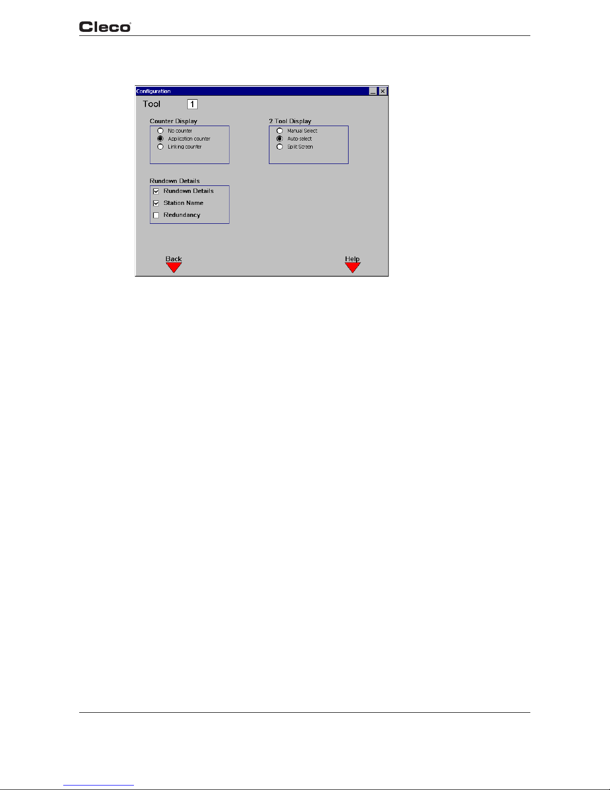
en03d141.fm, 11.03.2008 PL12EN-1300 2008-03 59
Programming
3
3.5.4 Run Screen / Configure
c00364en.bmp
Fig. 3-24: Run Screen / Configure
runcfg.txtS
Run Screen / Configure allows customization of the Run Screen display. The user may select the
display of counter information and/or rundown details. The counters are activated and reset
using the "Administration / Counter" screen. When the "Station Name" box is checked, and Link
ing is disabled, the Station Name programmed in "Advanced / System Settings" is displayed next
to the application number.
(2-Channel V2.xx.xx C2 only) The user has the option of having the Run Screen display automatically switch to the tool which has most recently reported results, or simultaneously displaying
the results from both tools. This is done by checking the Auto Select box, or Split Screen respec
-
tively.
runcfg.txtE

60 PL12EN-1300 2008-03 en03d141.fm, 11.03.2008
Programming
3
3.6 Oscilloscope
c00290en.bmp
Fig. 3-25: Oscilloscope Operation
oscope.txtS
The Oscilloscope function displays a Torque vs. Angle curve after each complete rundown in the
tightening direction. The curve is colored in alternating red and black lines to indicate the different
stages. A green box is also displayed on the trace to indicate the torque and angle limits. There
is a data point for each degree of angle rotation.
Archive
The Archive allows the user to display the last rundown with automatic update after each new
rundown, or to display the last five rundowns with an OK result and the last five rundowns with an
NOK result without automatic update.
Zoom
Using the Zoom indicators on the left side of the display, a specific area of the torque trace can
be enlarged. Using the up/down arrow keys, highlight the "Left" zoom indicator. Using the left/
right arrow keys set the orange vertical line to the left extent of the desired zoom window. Then
highlight the "Right" zoom indicator and set the right extent to the desired zoom window. Once
the window extents are set, pressing "Enter" will enlarge the trace to the desired zoom window.
Highlight the "Full" zoom indicator and press "Enter" to return the trace to the original unzoomed
size.
Cursor
The cursor (red cross-hatch) can be moved along the torque trace using the left and right arrow
keys. The actual torque and angle values of the cursor position are shown at the top to the dis
-
play.
Stage
The Stage softkey allows to select the corresponding stage by input of a stage number (0 to 6). If
you enter "0", the entire rundown is shown.

en03d141.fm, 11.03.2008 PL12EN-1300 2008-03 61
Programming
3
Rundown Indicator
At the bottom left of the display is the rundown indicator. The final torque and angle values are
displayed on either a green (OK) background or red (NOK) background.
Parameters
At the bottom of the display is a summary of the parameter settings for the rundown.
The Save softkey <F2> lets you print a hardcopy.
Note:
The TMEI does not provide access to the Oscilloscope screen.
oscope.txtE
3.7 Communication
3.7.1 Communications / Data Transmission
c00404en.bmp
Fig. 3-26: Data Transmission
commdata.txtS
From the Data Transmission Screen the Serial and Ethernet connections can be configured.
Serial
Protocol None, Standard, Standard2, PFCS, CT01 3964R,
Appolo
3.1, FEP
Port COM 1, COM 2
Baud Rate 2400, 4800, 9600, 14400, 19200, 38400, 57600, 115200
Data Bits 4, 5, 6, 7, 8
Parity None, Odd, Even, Mark, Space
Stop Bits 1, 1.5, 2
Flow Control None, Hardware, Xon/Xoff

62 PL12EN-1300 2008-03 en03d141.fm, 11.03.2008
Programming
3
Protocol allows the user to select between different data transmissions. If Appolo 3.1 is selected,
then after linking is OK, a special protocol for a label printer is sent to the programmed COM port.
With each other selection, the serial data transmission is sent after each cycle. The basic set
-
tings are Port, Baud rate, Data bits, Stop bits, Parity, and Protocol.
(2-Channel V2.xx.xx C2 only) The Standard, Standard2, and CT01 3964R serial communications
protocols can be configured as a unique serial port (COM1 or COM2) for each tool, or such that
a single serial port is shared between the tools. The transmitted "Tool Number" is a two-digit
ASCII field as programmed in Advanced / System Settings "Station Number". When the option
Advanced / System Settings: "Same for both tools" is checked, the Tool Number field is hardcoded as "01" or "02" as appropriate.
The following table details the transmission data for Standard:
Start End Length or Value Description
1 1 42 hex B
2 3 2 Digit ASCII To o l N u m b e r
4 5 2 Digit ASCII Parameter Set
6 17 12 Char ASCII Date and Time (YYMMDDHHMMSS)
18 24 7 Digit ASCII Peak Torque
25 31 7 Digit ASCII Low Torque Limit
32 38 7 Digit ASCII High Torque Limit
39 39 1 Char ASCII Status Torque Status Flag
L = low
A = accept
H = high
40 46 7 Digit ASCII Final Angle
47 53 7 Digit ASCII Low Angle Limit
54 60 7 Digit ASCII High Angle Limit
61 61 1 Char ASCII Status Angle Status Flag
L = low
A = accept
H = high
62 62 1 Char ASCII Status Overall Status Flag
A = accept
R = reject
63 64 2 Digit ASCII Link/Position
(Only for Linking)
65 66 2 Digit ASCII Number of linked positions
(Only for Linking)
67 67 0D hex CR (carriage return)
68 68 0A hex LF (line feed)

en03d141.fm, 11.03.2008 PL12EN-1300 2008-03 63
Programming
3
The following table details the transmission data for Standard2:
Start End Length or Value Description
1 1 42 hex B
2 3 2 Digit ASCII To o l N u m b e r
4 6 3 Digit ASCII Parameter Set
7 18 12 Char ASCII Date and Time (YYMMDDHHMMSS)
19 25 7 Digit ASCII Peak Torque
26 32 7 Digit ASCII Low Torque Limit
33 39 7 Digit ASCII High Torque Limit
40 40 1 Char ASCII Status Torque Status Flag
L = low
A = accept
H = high
41 47 7 Digit ASCII Final Angle
48 54 7 Digit ASCII Low Angle Limit
55 61 7 Digit ASCII High Angle Limit
62 62 1 Char ASCII Status Angle Status Flag
L = low
A = accept
H = high
63 63 1 Char ASCII Status Overall Status Flag
A = accept
R = reject
64 65 2 Digit ASCII Link/Position
(Only for Linking)
66 67 2 Digit ASCII Number of linked positions
(Only for Linking)
68 68 0D hex CR (carriage return)
69 69 0A hex LF (line feed)
If Part ID is ENABLED, then a 25 character ASCII part ID is transmitted prior to CR/LF.
TM-COM via COM1
When this feature is enabled the COM1 serial port is reserved solely to listen for an incoming
TM-COM connection. The COM2 port remains available for other functions; however, on the
TME-200 product COM2 is used to support the fieldbus interface and is not available if fieldbus is
activated.
Activating this feature requires restarting the controller. Once activated, this feature allows
another PC running TM-COM to connect via the COM1 serial port so that parameters may be
saved/loaded, etc.

64 PL12EN-1300 2008-03 en03d141.fm, 11.03.2008
Programming
3
Ethernet
Protocol None, Standard, PFCS, FEP
The ethernet settings include:
• Server IP Address
• Gateway
•Host
• Subnet Mask
• Port Address
The MAC address of the ethernet interface is displayed for informational purposes only and is
not configurable. See your network administrator for proper settings. To enable communications
with TM-COM, the IP address of for TM Unit, Gateway, and Subnet must be entered. For further
protocol descriptions contact a Technical Service Representative in Customer Satisfaction.
(2-Channel V2.xx.xx C2 only). When the ethernet "Standard" protocol is selected, there is one
connection made per controller. For all messages containing a "Station Number", the station
number for tool 1 is used. For the Rundown packet (#4), the "Spindle Number" field is 1 or 2
depending on the associated tool. Refer to Engineering Specification 543027 "Network Software
Specification" for more information.
commdata.txtE
3.7.2 Communication / Part ID
c00405en.bmp
Fig. 3-27: Part ID
comprtid.txtS
The Part ID configuration screens allow the user to specify the interface and functionality of the
Part ID used on the Run Screen and archived with the rundown data. Changes to the Part ID and
Configuration Data edit screens are saved when the “Communications” screen is exited (Run
Screen or Navigator button pressed). At this time the request to save the configuration is con
-
firmed with a password dialog box.
The Part ID may be entered manually from the run screen, input using a barcode reader attached
to a serial port, or transmitted through a FieldBus. A Part ID may consist of any sequence of
Alphanumeric characters, including spaces.

en03d141.fm, 11.03.2008 PL12EN-1300 2008-03 65
Programming
3
(2-Channel V2.xx.xx C2 only) The Part ID configuration settings are unique for each tool. The
Barcode Serial Interface can be configured as a unique serial port (COM1 or COM2) for each
tool, or such that a single serial port, and therefore each Part ID, is shared between the tools.
When the tools share a common Part ID source and serial port, the "Number of Characters" must
be identical for both tools.
Settings
Enable Defines the level of functionality of the Part ID
Disable The Part ID interface is completely disabled. No Part ID
information is present on the Run Screen, and a part ID
string of “(Disabled)” is archived with each rundown.
The part ID is not transmitted with the standard serial
protocol output data.
Enable The Part ID interface is enabled, and is present on the
Run Screen. A valid part ID is NOT REQUIRED to run
the tool. Following a rundown, the Part ID or the string
“(Not Valid)” is archived with the rundown data. The
Part ID is transmitted with the standard serial protocol
output data.
Enable Interlocked
The Part ID interface is enabled, and is present on the
run screen. A valid Part ID is REQUIRED to run the
tool. Following a rundown, the Part ID is archived with
the rundown data. The Part ID is transmitted with the
standard serial protocol output data. Following either a
good rundown (linking disabled) or good linking
sequence (linking enabled) the Part ID is invalidated
and the tool is disabled.
Print Interlocked
The Part ID interface is enabled, and is present on the
Run Screen. A valid Part ID is REQUIRED to run the
tool. Following a rundown, the Part ID is archived with
the rundown data. The Part ID is transmitted with the
standard serial protocol output data. The Part ID is valid
and the tool is enabled until the operator presses the
<F1> “Print” key on the Run Screen.
At this time, the Part ID is invalidated, the tool is disabled, and any rundowns which have not previously
been printed are sent to the parallel port printer inter
-
face.
Part ID Source Defines a source of the Part ID (i.e. Barcode reader through the serial port
or fieldbus). Fieldbus is only available if the Part ID option is enabled in the
Advanced\Fieldbus screen.
Number of
Characters
Defines the length of the Part ID, not including any termination characters
which may be sent by the barcode reader.
• Valid values are 1 to 25
Keypad Entry Defines whether or not a Part ID can be entered manually
Allowed A Part ID can be entered manually by highlighting the
Part ID box on the Run Screen and typing from the key
-
pad or an attached keyboard.
Disallowed The Part ID can not be entered manually from the run
screen.

66 PL12EN-1300 2008-03 en03d141.fm, 11.03.2008
Programming
3
Barcode Serial Interface
Defines the serial port used to interface to the barcode reader.
Note:
The default port for the serial barcode interface is COM2.
Port COM1, COM2
Baud Rate 2400, 4800, 9600, 14400, 19200, 38400, 57600, 115200
Data Bits 4, 5, 6, 7, 8
Parity None, Odd, Even, Mark, Space
Stop Bits 1, 1.5, 2
Flow Control None, Hardware, Xon/Xoff
Termination Defines what (if any) characters the barcode reader appends
to the barcode when transmitting to the serial interface
(None, CR/LF, LF, CR)
Configure Data
The Part ID: Configure Data screen is entered by pressing <F3> “Configure Data” from the Part
ID edit screen. Up to 12 position/value pairs may be entered, along with corresponding functions.
When a new Part ID is received by the controller, the table of entries is scanned. An entry which
matches a Part ID character “Value” in the corresponding “Position” causes the associated
"Function" to be engaged.
The entries are displayed in a table at the top of the screen. The “Position”, “Value”, “Function”
and “App/Group” edit boxes are at the bottom of the screen. Pressing the <F1> “Add” key causes
the current values in the edit boxes to be added to the table. All values are validated prior to
Data Function Allows the tool functionality to be automatically controlled based on the
Part ID. See “Configure Data” below.
None The Part ID characters have no control over the tool
functionality. The <F3> “Configure Data” soft key on the
Part ID configuration screen is disabled. NOTE: setting
this option to “None” does NOT cause Configure Data
table entries to be lost.
Configure Data The Position/Value pairs on the Configure Data screen
may be used to control the tool functionality. When
selected, the <F3> “Configure Data” key is enabled.
From the Configure Data screen, the user may enter
Position/Character pairs with associated functions to
control the tool based on the part ID.
Batch interrupt. Defines the way a new scanned ID number should be handled during
batching. Activated when "Enable" is set to "Enable Interlocked".
Reset Running batching will be interrupted and the scanned
PartID number will be used for the next batching. NOK
will be reported for any batch operation that is termi
nated prior to completion. NOK will be held for 1.5 s
after the batch is aborted, and then the new batch will
start.
Ask The user will be asked how to proceed with new
scanned number. (e.g. finish current batching or inter
-
rupt batching and start with new one.)

en03d141.fm, 11.03.2008 PL12EN-1300 2008-03 67
Programming
3
insertion in the table. New entries are always inserted at the END of the table. Pressing the <F2>
“Delete” key brings up a dialog box in which the user types the table entry number to be deleted.
The delete function may be aborted by selecting “Cancel”. Pressing the <F3> “Part ID” key
returns the user to the Part ID configuration screen.
Note:
When the table is scanned for a Part ID Position/Value pair match, the scanning is terminated after the first match in the table has been found. The Part ID character positions are
numbered from left to right.
Position 1-<Number of Characters>
Value Any Alphanumeric character
Function Use Application X, Use Tightening Group X, Tool Enable,
Tool Disable
App/Group 1-255 when function "Use Application X" is selected
1-8 when function "Use Tightening Group X" is selected
Ignored when function "Tool Enable" or "Tool Disable" is
selected
comprtid.txtE
3.7.3 Communications / Printer
c00291en.bmp
Fig. 3-28: Printer
commprin.txtS
From this screen the user can configure the setup for the Parameter/Rundown Printer. When
Parallel Enable is checked, rundown data is automatically sent to the parallel port whenever a full
page has been queued. Unprinted rundowns are sent to the printer whenever any other print
request is made (typically by pressing Print <F1> from the Run Screen). The Filter parameter
allows the user to select whether All, OK, or NOK rundowns are printed. This filter applies to both
the automated printing of rundowns (Parallel Enable), and the manual printing of rundowns
(pressing Print <F1> from the run screen). Only the Centronics printer interface is supported. The
Font Size selection can be used to adjust the size of the printed output.
Note:
The Printer must be on before you switch on your TME. This will guarantee correct initialization
of the printer.
commprin.txtE

68 PL12EN-1300 2008-03 en03d141.fm, 11.03.2008
Programming
3
3.7.4 Communications / Work Cell
c00389en.bmp
Fig. 3-29: Work Cell
workcell.txtS
From this screen, the user can add IP addresses to the list of remote units. To add a remote unit,
enter the IP address and select Add <F1>. To delete a remote unit, select Delete <F2> and enter
the position number of the IP address. To get the status of the remote unit select Verify <F3>.
workcell.txtE
3.8 Tool Setup
c00293en.bmp
Fig. 3-30: Tool Memory
toollist.txtS

en03d141.fm, 11.03.2008 PL12EN-1300 2008-03 69
Programming
3
The Tool memory data is displayed for the selected tool and redundancy. Only the Field Torque
Calibration (±20% of nominal) and the static current factor are editable, in order to correct the
torque calibration of the selected tool. If no Tool memory is available, then all data is programma
-
ble.
In case a tool with memory is changed to another tool with memory of the same type the tool will
continue to work without any necessary changes. In case the tool is changed to a tool without
memory or to a different type, then after power on or when pressing the start switch a message is
displayed which prompts the user to verify the Tool Setup.
If tool memory is not available, <F1> and <F2> will change to Standard Tools and Fixtured Tools,
respectively.
Pressing the Standard Tools <F1> key will allow the user to select from a library of predefined
hand tools. This library can be used to program the tool parameters when tool memory is not
available or to change the existing tool memory values.
Pressing the Fixtured Tools <F2> key will allow the user to select from a library of predefined fixtured tools. This library can be used to program the tool parameters when tool memory is not
available or to change the existing tool memory values.
The Safety Shutoff mechanism uses current monitoring to turn off the tool in the event of a transducer failure during a rundown, thereby preventing unexpected high torque. If an application
experiences undesired shutoffs due to current spikes, this feature can be disabled at the discre
tion of the user. When disabled, the tool will still be shut off if the measured current exceeds what
is allowable for that tool.
Note:
Calibration with an external (master) transducer and torque monitor traceable to a third
party standard is only required for the following circumstances:
Before putting a new tool in service, after the tool has been repaired; continuous reading
errors; periodic basis of 6 months or 100,000 cycles (whichever occurs first), or as man
-
dated by Quality Assurance.
Each transducer's calibration values should be documented for future reference.
TMEI Only
c00394en.bmp
Fig. 3-31: Tool Setup

70 PL12EN-1300 2008-03 en03d141.fm, 11.03.2008
Programming
3
The Tool Setup screen for the TMEI does not display a Transducer type, and no Redundancy
information.
toollist.txtE
3.9 Tool Library
3.9.1 Tool Library
c00294en.bmp
Fig. 3-32: Tool Library
toollib.txtS
Using the arrow keys, move the orange highlight to the desired tool. Press ENTER to select that
model or ESC to exit. If a model is selected these new parameters will be used as the tool
parameters. Note that it is extremely important that the correct model is chosen to avoid damage
to the tool or injury to the worker.
Use Page Up <F2> and Page Down <F3> when appropriate to view more tool models.
toollib.txtE

en03d141.fm, 11.03.2008 PL12EN-1300 2008-03 71
Programming
3
3.10 Statistics
3.10.1 Statistics / Chronological History
c00297en.bmp
Fig. 3-33: Chronological History
chrono.txtS
The user can view the Chronological History of rundowns for any or all applications, filtered using
the criteria from Statistics / Parameters. This history includes time, date, application, status,
torque, angle, and Part ID.
Use Prev Page <F1> and Next Page <F2> in order to go through the Chronological History. At
the top right the Entries: XXXX / YYYY display indicates the number of Chrono entries matching
the filter criteria / the total number of chrono entries stored in the database. The Page XXXX /
YYYY indicates the current page being displayed / the total number of pages of entries matching
the filter criteria. The Clear Chrono <F3> soft key allows the user to delete all rundowns.
To view additional details on a particular rundown, use the up or down arrow keys to highlight the
desired rundown, then press the <ENTER> key.

c00417en.bmp
72 PL12EN-1300 2008-03 en03d141.fm, 11.03.2008
Programming
3
Fig. 3-34: Chronological History / Rundown Information
Additional rundown information can be viewed for a rundown by using the up and down arrows to
highlight the rundown, then press <Enter>.
c00414en.bmp
Fig. 3-35: Chronological History TMEI
The TMEI Statistics screen does not display the Peak TQ column.
chrono.txtE

en03d141.fm, 11.03.2008 PL12EN-1300 2008-03 73
Programming
3
3.10.2 Statistics / Graphs
c00357en.bmp
Fig. 3-36: Statistical Histogram
c00361en.bmp
Fig. 3-37: Range

c00358en.bmp
74 PL12EN-1300 2008-03 en03d141.fm, 11.03.2008
Programming
3
Fig. 3-38: X-Bar
graphs.txtS
The Statistics / Graphs screens are used to view the statistics from the selected rundowns in
summary and in graphical form. Refer to Chapter
4 Statistics, page 97 for a description of the
meaning of the statistics values. The rundowns are selected by the "Application" on the Graphs
screen, and are further filtered using the criteria in the Statistics / Parameters screen. The user
may also select the Subgroup Size (2-25) or switch between calculations for Torque and Angle.
The <F3> soft key is used to toggle the view between the Histogram, Range, and Xbar charts.
The <F1> soft key is used to toggle between Manual and Automatic update. In Automatic mode,
the statistics are recalculated, and the graph redrawn, whenever a new rundown is entered into
the Chronological History. In Manual mode, the recalculation is done only when the user presses
the <F2> "Refresh" key. With large data sets, it may be desirable to set Manual update mode for
performance reasons.
The left side of the screen contains a textual summary of the statistical calculations. The table at
the bottom of the screen displays the relevant programmed parameters for the currently selected
application.
The TMEI does not provide access to the Graphs screen.
Note:
If any of these programmed parameters (Min / Max / Turnoff Torque / Angle) is changed,
any previous rundowns for this application are no longer valid for statistical calculation
purposes. When a Min / Max / Turnoff value is changed, an entry is made in the Chrono
-
logical History indicating the end of valid rundowns for statistical calculations:

en03d141.fm, 11.03.2008 PL12EN-1300 2008-03 75
Programming
3
graphs.txtE
c00359en.bmp
Fig. 3-39: Chronological History
3.10.3 Statistic / Parameter
c00401en.bmp
Fig. 3-40: Statistical Parameter
statpara.txtS
From the Parameter Screen the user is able to apply a filter to the chrono data.
Filter
1. Select from the pull down menu: "All, OK, or NOK" rundowns.
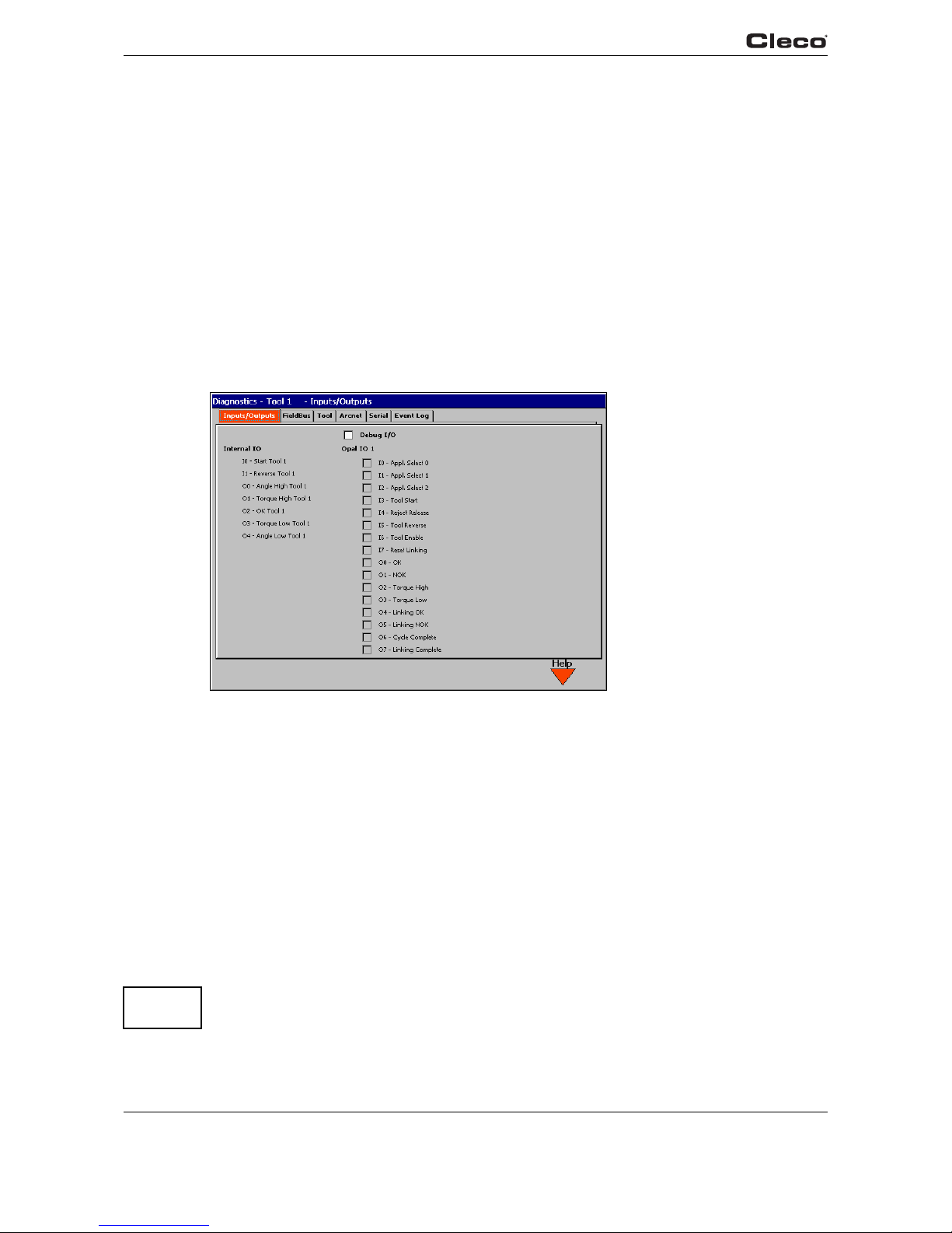
76 PL12EN-1300 2008-03 en03d141.fm, 11.03.2008
Programming
3
2. Enter a number for the "Count (Last n)" field. A value of 0 disables this filter criteria.
3. Enter the Start date/time and the End date/time.
The parameters are verified and updated whenever the selected field is changed, or when
the Parameter screen is exited. The parameters selected from this screen apply to both the
Chrono History and Graphs displays.
Export Chrono
This softkey <F3> allows the user to send the filtered data to the available disk media or the
printer.
statpara.txtE
3.11 Diagnostics
3.11.1 Inputs / Outputs
c00298en.bmp
Fig. 3-41: Inputs / Outputs
opaldiag.txtS
A light box for each available input and output is displayed to show the current status. In case an
input or output is active, the light will be green.
You will find a detailed description of these signals under 3.4.2 Advanced Application Builder /
Inputs, page 41, 3.4.3 Advanced Application Builder / Outputs, page 43.
(2-Channel only) The Diagnostics Inputs / Outputs screen displays the status of the +24V digital
inputs and outputs for both tools simultaneously.
Debug I/O
Debugging I/O is inherently dangerous as toggling on any input or output can trigger another
response. The outputs can be connected to other devices causing movement of the tooling.
Note:
Use extreme caution when activating this feature!

en03d141.fm, 11.03.2008 PL12EN-1300 2008-03 77
Programming
3
When the Debug I/O is activated, you may select input and output channels to be activated manually by selecting the check box that is located to the left of the desired signal. The On button
<F1> key, Off button <F2> key and Restore button <F3> key may be pressed to change the state
of the signal. Manually turning on/off signals overrides the system signal on the selected chan
nels simultaneously. The system signal is restored on all channels when the restore button is
pressed and when the diagnostics menu is exited. The state of all signals will remain intact when
other menu tabs are selected.
Note that fieldbus inputs that are activated will override inputs from the 24v digital I/O in some
cases; thus, activating a digital input under this scenario may not produce a system response.
This feature may not be activated from TM-COM except for TMEM.
opaldiag.txtE
3.11.2 Diagnostic / Fieldbus
c00403en.bmp
Fig. 3-42: Fieldbus
diafield.txtS
A light box for each available input and output is displayed to show the current status. In case an
input or output is active, the light will be green.
You will find a detailed description of these signals under 3.4.4 Advanced Application Builder /
Fieldbus, page 46.
Debug I/O
Debugging I/O is inherently dangerous as toggling on any input or output can trigger another
response. The outputs can be connected to other devices causing movement of the tooling.
Note:
Use extreme caution when activating this feature!
When the Debug I/O is activated, you may select input and output channels to be activated manually by selecting the check box that is located to the left of the desired signal. The On button
<F1> key, Off button <F2> key and Restore button <F3> key may be pressed to change the state
of the signal. Manually turning on/off signals overrides the system signal on the selected chan
nels simultaneously. The system signal is restored on all channels when the restore button is

78 PL12EN-1300 2008-03 en03d141.fm, 11.03.2008
Programming
3
pressed and when the diagnostics menu is exited. The state of all signals will remain intact when
other menu tabs are selected.
This feature may not be activated from TM-COM except for TMEM.
diafield.txtE
3.11.3 Tool / Calibration
c00299en.bmp
Fig. 3-43: Tool / Calibration
testcali.txtS
This test function cyclically recalibrates the system with the values used immediately before the
start of a rundown. The spindle must be released for this function! The values "Offset Voltage"
and "Full Scale Voltage" of the torque transducer are displayed. If redundancy is activated, the
values of the second transducer are displayed. If a value is out of tolerance, it is shown in red.
Rated values and tolerances:
Value Rated value Tol erance
Calibration offset: 0 V +/-200 mV
Calibration voltage: 5 V +/-150 mV
Note:
Entering a password and viewing of a warning is required prior to running any "active"
tool diagnostics.
Note:
Not available on the TMEI.
testcali.txtE

en03d141.fm, 11.03.2008 PL12EN-1300 2008-03 79
Programming
3
3.11.4 Tool / Angle Encoder
c00301en.bmp
Fig. 3-44: Tool / Angle Encoder
testangl.txtS
The tool start switch starts the spindle with a speed of 30% of the maximum. After one revolution
of the output shaft (set angle 360 deg), measured with the tool resolver, it is stopped. During a
permanently adjusted dwell time of 200 ms any further angle pulses occurring are traced. The
total result is shown as "Actual Angle". The "Shut-off Torque" displayed is the torque prevailing at
shut-off or the maximum value reached during the dwell time if that value is higher than the
torque at shut-off.
If the test run is not terminated by a monitoring criterion, the total result equals or is higher than
360 degrees and is evaluated as okay ("OK"). Monitoring criteria are the torque of transducer 1
and a monitoring time. If the torque of transducer 1 exceeds 15% of its calibration value (even
during the dwell time), or if the monitoring time of 5 seconds is elapsed, the test run is terminated
with "NOK".
The user must check himself, if the output shaft has actually turned by the value indicated (e. g.
put mark on the spindle). If the angle reached by the output shaft does not agree with the value
displayed, either the angle factor is or the resolver is defective.
testangl.txtE

80 PL12EN-1300 2008-03 en03d141.fm, 11.03.2008
Programming
3
3.11.5 Tool / Voltages
c00300en.bmp
Fig. 3-45: Tool / Voltages
testvolt.txtS
The table displays the measured voltages of a channel.
These are the most important supply voltages on the measuring board, required for proper
torque and angle measurement. Therefore, these must be monitored continuously. If a voltage is
out of tolerance, it is shown in red.
Designation voltage Rated value Tol erance
Logic voltage: +5 V +250 mV/-400 mV
Pos. analog Positive analog
voltage
+12 V ±600 mV
Neg. analog Negative analog
voltage
-12 V ±900 mV
testvolt.txtE

en03d141.fm, 11.03.2008 PL12EN-1300 2008-03 81
Programming
3
3.11.6 Tool / TQ Measurement
c00302en.bmp
Fig. 3-46: Tool / TQ Measurement
testmeas.txtS
This test function recalibrates the system with the values used immediately before the start of a
rundown. The spindle must therefore be released still when this function is called up! Then the
tool is started at zero speed and the torque is continuously measured and displayed. The field
"Current torque" displays the current torque, "Peak torque" displays the highest value measured
since the start of the function. If "Redundancy" is activated, the values of the second transducer
are also displayed.
Note:
Not available on the TMEI.
testmeas.txtE

82 PL12EN-1300 2008-03 en03d141.fm, 11.03.2008
Programming
3
3.11.7 Tool / Speed
c00314en.bmp
Fig. 3-47: Tool - Speed
testtach.txtS
When you press the tool start switch, the spindle starts with maximum speed. The current output
shaft speed is displayed. To achieve this, the angle factor must have been entered correctly,
since the integrated speed measurement is derived from the resolver signals. When you release
the start switch the spindle stops. As a safety function the torque is monitored by the tool trans
-
ducer. If it exceeds 15% of its calibrated value, the tachometer function is terminated.
testtach.txtE

en03d141.fm, 11.03.2008 PL12EN-1300 2008-03 83
Programming
3
3.11.8 Tool / Tool Memory
c00316en.bmp
Fig. 3-48: Tool / Tool Memory
testiden.txtS
Provides a constant update of the tool memory data in the attached tool.
testiden.txtE
3.11.9 Arcnet / Map
c00303en.bmp
Fig. 3-49: Arcnet / Map
arcmap.txtS
The ARCNET map displays information on the current number of participants in the network,
their ARCNET-ID, status, serial and software number and identification. The display is continu
ously updated, e. g. if the connection with a participant is interrupted, it is removed from the table,
or if a new participant is added, it is added to the ARCNET table.
arcmap.txtE

84 PL12EN-1300 2008-03 en03d141.fm, 11.03.2008
Programming
3
3.11.10 Arcnet / Statistic
c00304en.bmp
Fig. 3-50: Arcnet / Statistic
arcstat.txtS
The ARCNET statistics allow to check the stability of the field bus system. There are two different
statistics:
arcstat.txtE
• For all external hardware components (bridges, TMs)
• For the station controller
The following is a description of the parameters required for stable operation.
TM Bridge
Description
Reconfigurations Change upon each reset of a participant
Own reconfigurations Change upon each reset or severe failure
Excessive NAK Should be stable
New next ID Change upon switch-off/on of downstream participant
CRC error Should be stable
Lost Token Should be stable
Send repetitions Should be stable
Send termination Should be stable
Receive terminations Should be stable
Command errors Should be stable
Unassignable ACKs Should be stable
ACKs with Bit 14/15-Packets without CPT protocol Should be stable
Input queue overflow Should be stable
Packet not assigned by node Should be stable
Discarded input packets Should be stable

Host Driver Statistics
Reconfiguration Change upon each reset of a participant
Host reconfiguration Change upon each reset or severe failure
CRC error Should be stable
Outbound packets - Inbound packets - Next ID Change upon switch-off/on of downstream participant
Excessive NAK Should be stable
Lost Token Should be stable
Statistics of ARCNET Manager
Broadcasts received Synchronous starts Stopped synchronous starts -
CRC error Should be stable
Timeout A Should be stable
Timeout B Should be stable
Wrong ARCNET ID received Should be stable
Packets not for host Should be stable
ACKs in READY status
ACKs in ERROR status Should be stable
Unassignable ACK Should be stable
ACKs with Bit 14/15
Packets without CPT protocol Should be stable
Input queue overflow Should be stable
Packet not assigned by node Should be stable
Discarded input packets Should be stable
en03d141.fm, 11.03.2008 PL12EN-1300 2008-03 85
Programming
3
3.11.11 Serial
c00305en.bmp
Fig. 3-51: Serial Port Diagnostics

86 PL12EN-1300 2008-03 en03d141.fm, 11.03.2008
Programming
3
serial.txtS
The serial diagnostics allows the user to test the selected COM port by displaying sent (black
text) and received data (red text).
The <F1> “Start Hardware Test” transmits 10 characters. It reads back a byte based on the CTS
signal. For this test an external Adapter with shorted pins is necessary. Note that serial data dis
-
play is only available with serial data transmission configured as “Standard” or “CT01 3964R”.
The Clear Screen <F2> soft key will clear the displayed bytes
The <F3> soft key toggles the transmission record display between ASCII and hexadecimal.
serial.txtE
3.11.12 Event Log
c00387en.bmp
Fig. 3-52: Event Log
eventlog.txtS
The Event Log allows viewing of errors and events that aid in diagnosing controller or operational
problems. The log displays system startup action, abnormalities detected by the STMH servo,
and field bus communications problems. The <F1> Prev Page and <F2> Next Page function
keys are used to navigate through the list. Up to 999 events are stored. The <F3> "Clear Event
Log" key is used to delete the archive of events
eventlog.txtE

en03d141.fm, 11.03.2008 PL12EN-1300 2008-03 87
Programming
3
3.12 Utilities
3.12.1 Utilities / Installed Versions
c00395en.bmp
Fig. 3-53: Installed Versions TME-100
c00396en.bmp
Fig. 3-54: Installed Versions TME-200

c00397en.bmp
88 PL12EN-1300 2008-03 en03d141.fm, 11.03.2008
Programming
3
Fig. 3-55: Installed Versions TMEI
SWInfo.txtS
The software and firmware revisions active on the controller are listed on this screen.
SWInfo.txtE
3.12.2 Utilities / Software Update
c00398en.bmp
Fig. 3-56: Update Software TME-100

c00399en.bmp
en03d141.fm, 11.03.2008 PL12EN-1300 2008-03 89
Programming
3
Fig. 3-57: Update Software TME-200
updateso.txtS
One or more upgrade/update packages may be installed from this screen. A single “package”
may contain system software, servo firmware, help file updates, or a combination of these and/or
others.
The active software package indicates which package the running software was loaded from
when the controller was started. After an update or upgrade of the system software, the active
package will not change until the controller is restarted.
Package date/time information indicates when the package was created and its contents were
collected and stored.
The <F3> soft key reads the storage device and displays the contents. The storage device may
contain many packages for different products, but only valid packages intended to be installed on
the targeted unit (e.g. TME-200, TMEM) are listed. The UP and DOWN arrow buttons may be
used to navigate to a listed package and select it for installation by pressing the <ENTER> but
-
ton. Multiple packages may be selected for installation at one time.
The <F2> soft key loads all selected packages to the targeted unit, unpacks and installs them.
A single firmware update package is installed on each tool in the controller, eliminating the need
to install twice.
If installing to a remote unit from a Cell Manager unit, you should first install to all remote controllers prior to installing to the Cell Manager unit. All units of a cell must be running the identical version of software in order remote access to be possible.
CAUTION!
During ANY update the system power must not be switched off!
updateso.txtE

90 PL12EN-1300 2008-03 en03d141.fm, 11.03.2008
Programming
3
3.12.3 Utilities / System Settings
c00408en.bmp
Fig. 3-58: System Settings TME-100
c00409en.bmp
Fig. 3-59: System Settings TME-200
utilsysset.txtS
System Settings displays the total memory and the available memory of the controller.
On TME-200 units, the screen off timer can be set to the number of minutes the screen backlight
will remain activated while the controller is idle. The backlight is turned off when the timer
expires. The backlight is reactivated whenever a keypad key is pressed, an external input signal
is changed, or when the tool is started.

en03d141.fm, 11.03.2008 PL12EN-1300 2008-03 91
Programming
3
Setting the screen off timer to 0 minutes will keep the backlight activated indefinitely. It is recommended that the timer be activated so that the backlight lifetime can be extended.
Uncheck the Activate screen when tool I/O changes box if the screen backlight should be turned
on only when a keypad button is pressed or a keyboard key is pressed. Otherwise, any change in
external I/O (e.g. tool enable, tool start) will turn on the screen and reset the screen off timer.
The screen off timer setting is not available for TME-100 or TMEM units, and therefore is not displayed when connected to either via TM-COM or the Cell Manager.
utilsysset.txtE
3.13 Administration
3.13.1 Administration / Load/Save
c00307en.bmp
Fig. 3-60: Load / Save
loadsave.txtS
Using the check boxes, the user can select the parameters to load or save.
The Load <F2> soft key searches the disk media for previously-saved files and presents a dialog
so that the desired file can be selected.
The Save <F3> soft key saves the selected items to the disk media in one file. A dialog is presented that requests a file name to be specified, and this name can be modified if desired.
Unchecking the Load IP Settings box will preserve the active TCP/IP Ethernet settings whenever
communications settings are loaded.
loadsave.txtE

92 PL12EN-1300 2008-03 en03d141.fm, 11.03.2008
Programming
3
3.13.2 Administration / Print
c00308en.bmp
Fig. 3-61: Print
setuppri.txtS
Using the check boxes, the user can select the items to print. These will be sent to the printer or
to a file on the disk media if selected.
If print to file is checked, then the file name is activated to the right and may be edited. Default
names are provided using the file name prefix and the checked item to print.
The Print <F3> soft key will start printing.
setuppri.txtE

en03d141.fm, 11.03.2008 PL12EN-1300 2008-03 93
Programming
3
3.13.3 Administration / Password
c00309en.bmp
Fig. 3-62: Password
password.txtS
The Password displays the active users and corresponding rights. There are different rights
available for Programming, Statistics, Diagnostics and Administration. The date and time of the
last entry changes automatically when parameters are changed. The Password function sup
-
ports up to ten different users plus a master password.
Pressing Add User <F1> it is possible to add a new user. If the first user does not activate the
“Administration” rights he will get them automatically.
Pressing Delete User <F2> it is possible to delete a user. If the last user does not have the
“Administration” rights he will get them automatically.
By checking the "Read Protected" box, a password is required when entering a screen from the
Navigator menu, rather than after programming changes have been made.
password.txtE

94 PL12EN-1300 2008-03 en03d141.fm, 11.03.2008
Programming
3
3.13.4 Administration / Date & Time
c00310en.bmp
Fig. 3-63: Date & Time
datetime.txtS
Using the radio buttons the user can select European or US format for time and date.
The Checkbox for Winter/Summer will account for Daylight Savings Time.
The System Time and date will be updated when the Accept <F3> soft key is pressed.
datetime.txtE

en03d141.fm, 11.03.2008 PL12EN-1300 2008-03 95
Programming
3
3.13.5 Administration / Language
c00360en.bmp
Fig. 3-64: Language
language.txtS
The Administration / Language screen is used to select the language for the user interface. Use
the up and down arrow keys to highlight the desired language, then press <ENTER> to confirm.
language.txtE

96 PL12EN-1300 2008-03 en03d141.fm, 11.03.2008
Programming
3
3.13.6 Administration / Counter
c00365en.bmp
Fig. 3-65: Counter
counters.txtS
From the Administration / Counter screen, the user may view, enable, disable, or reset any of the
available counters. Counters are provided for each application (1-255) and for each linking group
(1-8). The view is toggled between Application and Linking view by selecting either Application or
Linking in the pull-down menu.
Each counter may be enabled by highlighting the desired type of operation in the "Status" pulldown menu, then pressing the Enter key. When "- Backoff" is selected, the counter is enabled,
and the current count is decremented each time the tool is started in the backoff direction. The "Backoff" mode is not available for Linking counters.
The "Auto Reset Mode" allows the counter to operate like a batch counter. In this mode, the
counter is automatically reset to zero after the total number of rundowns (OK + NOK = Size) or
number of OK rundowns (OK = Size) equals the value programmed in the "Size" edit box.
Each counter may be reset manually by highlighting the "Reset" checkbox and pressing
<ENTER>.
Note:
The counters are not enabled, disabled, or reset until the Accept <F3> soft key is pressed,
and the correct password (if enabled) and confirmation are provided.
counters.txtE

en04d141.fm, 11.03.2008 PL12EN-1300 2008-03 97
Statist ics
4
4Statistics
4.1 Understanding Statistics
Your unit provides a wide array of statistical and data reports (charts) for the control of manufacturing processes. The following provides a description of the control chart for variables and an
outline of the procedure for its use. Known as the
-R chart (pronounced X-bar-R), the chart for
variables can be used whenever a quality characteristic can be measured and expressed by a
numerical value. When properly used, it can bring substantial improvement in product quality and
a reduction of scrap and rework.
When we control a process, we monitor the variation of the characteristics that are important to
the product. During production, samples from the process are measured. By plotting the results
of these measurements on the control chart, we are able to see if the process is operating in a
stable manner (in a state of statistical control), or if the pattern has been disturbed by an event
that drives the process out of control. In other words, the control chart tells us what the process is
doing - when to take action and when to leave it alone.
Although it is a powerful tool, the -R Control Chart is easy to use. Only an understanding of a
few basic statistical concepts and the use of simple arithmetic is needed.
4.1.1 The Nature of Variation
Variations in measured product are always present because of random fluctuations and inconsistencies in machines, material, and operator performance. No two items produced are exactly
alike.
When variation is random and stable, the process is in a state of statistical control (see graph
4-1a). The process has an identity, and its performance is predictable. The stable pattern of variation is caused by conditions that are inherent to the manufacturing system, such as spindle run
out, bearing clearances, differences in material properties, accuracy of measuring equipment,
and operator performance. We call this "common cause" variation.
When variation is sporadic and unstable, the process is out of statistical control (see graph
4-1b). The process loses its identity and is no longer predictable. The unstable pattern is caused
by such events as tool breakage, tool wear, bad material, and operator error. This is called "spe
-
cial cause" variation.
Fig. 4-1: a) Common Cause Variation Fig. 4-1: b) Special Cause Variation

98 PL12EN-1300 2008-03 en04d141.fm, 11.03.2008
Statistics
4
4.1.2 The Normal Curve
Most processes in statistical control have a fixed pattern of variation. The mathematical curve
that describes this pattern is known as the normal curve (see graph 4-2a). The normal curve is
symmetrical about the average. It is high in the middle and becomes smaller as the distance from
the average increases. Since the shape resembles a bell, it is sometimes referred to as a bell
curve.
The normal curve is defined by two conditions - the average of all items produced, and the
amount of variation from the average. We can think of these as the center and width of the bell,
respectively. The center is the arithmetic average of all items produced. The width is expressed
in terms of the standard deviation which is a statistical calculation for the amount of variation
from the average. The standard deviation, represented by the Greek letter sigma (σ), holds a
fixed relationship to the normal curve, as follows (see graph 4-2b):
• 68% of all items produced will be within +1σ of the average (two sigma spread).
• 95% will be within +2σ of the average (four sigma spread).
• 99.7% will be within +3σ of the average (six sigma spread).
These two characteristics - the average and the standard deviation - provide the foundation for
statistical process control. By taking sample measurements during production, we can predict the
average value and the amount of variation for all items produced.
68%
95%
99.7%
1σ1σ2σ 2σ 3 σ3σ
Avg.
Avg.
Fig. 4-2: a) The Normal Curve Fig. 4-2: b) Areas Under The Normal Curve
4.1.3 The Procedure
The procedure for establishing a statistical process control program consists of three phases.
The first is to obtain statistical control - a state of random and stable variation. The second is to
establish process capability. A state of statistical control in itself does not assure that the process
is capable of meeting the specification. The limits of variation must be equal to or less than the
total specification tolerance. The third is to monitor the process throughout production using the
control chart, to detect and correct conditions that upset the stable pattern of variation.
Use of the -R Control Chart includes the following steps:
1. Select the Characteristic
Since a separate chart is required for each characteristic, practical considerations limit use to
selected requirements. A good candidate is a characteristic that is important to the function of the
item. Others include those that are causing a high cost loss because of scrap or rework, and
those that require evaluation by destructive testing.

en04d141.fm, 11.03.2008 PL12EN-1300 2008-03 99
Statist ics
4
2. Designate the Sample Size
It is usually desirable to keep the sample size small so that variation within the sample is at a
minimum, but not so small that statistical validity is lost. The control chart described in this docu
ment is structured for a sample size of five units. If a sample other than five is selected, the manufacturing or quality engineer can provide alternate factors for use in calculating the control limits
and standard deviation (Steps 8 and 10).
3. Designate the Sample Frequency
Selection of the sample frequency should be based on economic considerations for the cost of
measurements and the potential loss that may occur if samples are not taken often enough.
Early in the production run, samples should be taken more frequently and then extended after
satisfactory control is verified. The frequency may be expressed as a time interval or as a portion
of quantities produced.
4. Assure Measurement Accuracy
Measurement accuracy is mandatory for successful statistical control. Measuring and test equipment must be of a type suitable for the characteristic being evaluated, and must be calibrated
and properly used. Decisions resulting from the analysis of a control chart will be no better than
the measurement data.
5. Complete the Data Sheet Headings
It is important that all heading entries on the data sheet be completed. They include the part
number and description, the operation performed, the name of the operator, the machine or
equipment used, and the specification limits. The data sheet and control chart can provide evi
dence of quality for use by the Quality Assurance organization if the information is properly
recorded and traceable to the products manufactured.
6. Start Production
Take samples of five units (preferably consecutive units produced) at the designated frequency,
and record each measurement (X) on the data sheet. For each sample of five calculate the aver
-
age ( ) and range (R), and plot the results on the chart (see graph 4-3).
0
4
8
12
16
20
R
X
- Add the five measurements and divide the sum by five.
For a sample of five, it is often easier to multiply the sum
by two and move the decimal one place to the left.
R - Substract the smallest measurement from the largest.
(Note that the range can never be negative.)
R
ange
A
verage
Fig. 4-3: Entries for Range and Average

100 PL12EN-1300 2008-03 en04d141.fm, 11.03.2008
Statistics
4
7. Calculate Process Center Lines
After data for 20 samples of five have been plotted, calculate the center lines for both the average and range plottings.
The center line for the average chart is known as the grand average ( ) and is the average of all
of the sample averages. This is the value that best represents the size of all measurements:
X
X
n
Σ
where Σ is used to indicate the sum of the sample averages, ( ), (be careful to observe the
+ and - signs), and n the number of samples, in this case 20.
Similarly, the center line for the range chart ( ) is the average of the ranges for all samples.
R
R
n
Σ
Draw solid lines on the control chart for values representing and (see graph 4-4).
R
0
4
8
12
16
20
X
R
X
UCL
X
LCL
UCL
R
LCL
R
ange
A
verage
Fig. 4-4: Drawing The Center Lines And Control Limits
8. Calculate Control Limits
Calculate the upper and lower control limits (UCL and LCL) using the following formulas and the
values previously calculated for the grand average (
) and the average range ( ). (Factors are
for samples of five units only.)
X
x
UCL
+0.577(R)
X
x
LCL
0.577(R)
X
R
UCL
+2.114(R)
0
R
LCL
A
verage
Range
Note: For a sample size of six or less, the lower control limit for the range is zero.
Plot the limits on the control chart as broken lines.
9. Evaluate for Statistical Control
Analyze the control chart to see if the process is in a state of statistical control. Variation should
be random about the center lines for both averages and ranges, with all points within the control
limits. If these conditions are not satisfied, special cause variation may be present.
 Loading...