

P1891E/EN 09/07
N O R T H A M E R I C A (N A)
Cooper Power Tools
P.O. Box 1410
Lexington, SC 29071-1410
E U R O P E (E U)
Cooper Power Tools GmbH & Co. OHG
Postfach 30
D-73461 Westhausen, Germany
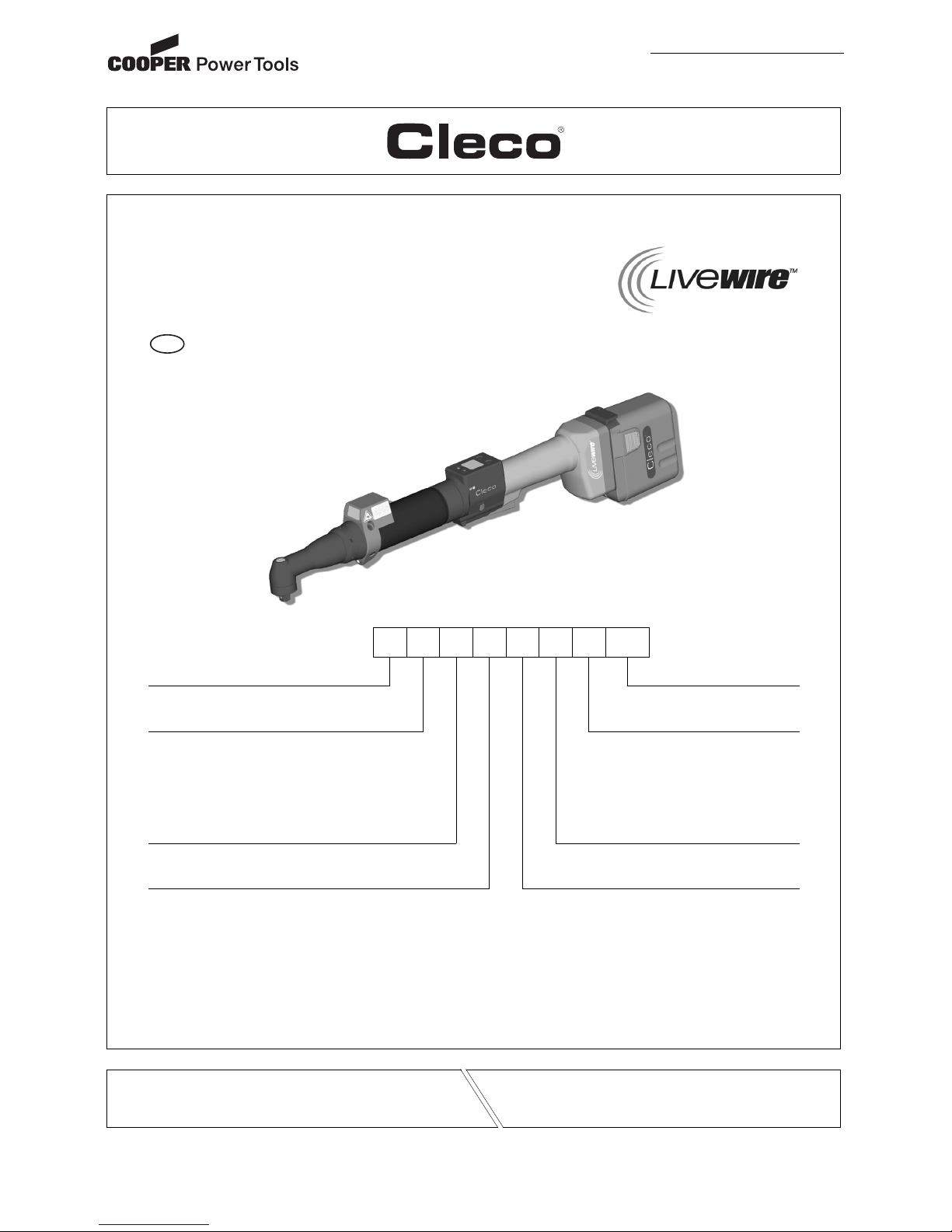
47BA…B…
Cordless EC angle nutrunner
47 B A … … B … AM3
Series Attachment
47 AM3 – Square 3/8"
Power Max. Torque
B – Battery 15 –- 15 Nm
21 – 21 Nm
28 – 28 Nm
35 – 35 Nm
50 – 50 Nm
Too l S ty le Battery
A – Angle B – 26 V
Feature 1 (Data Transmission) Feature 2 (Scanner)
– IrDA S – Barcode Scanner
F – RF915MHz – None
R – RF868 MHz
W – WLAN: WEP, WPA
X – WLAN: WEP, WPA/WPA2, 802.1x
EN
Retain for future reference!
For additional product information visit our website at http://www.cooperpowertools.com
Instruction Manual

2 P1891E/EN 09/07 91a_ Deckblatt en.fm, 24.09.2007
For this Instruction Manual
This Instruction Manual is intended for all persons who work with this tool but do not do any programming work.
The Instruction Manual
• provides important notes for safe and effective use.
• describes the function and operation of the cordless EC angle nutrunner.
• serves as a reference work for technical data, service intervals
and spare part orders.
• provides information on options.
For more information on the operation of the 47BA with the control electronics see
• programming manual controller TMEB-200, no. P1895E
• programming manual TMEB-COM, no. P1898E for PC application
In the text:
47BA represents all models of the
cordless EC angle nutrunner as described here.
➔ refers to required actions.
• refers to lists.
Identification text:
Identification graphic:
Copyright protection
Cooper Power Tools reserves the right to modify, supplement or improve the document or the
product without prior announcement. This document may not be reproduced in any way, shape
or form, in full or parts thereof, or copied to another natural or machine readable language or to a
data carrier, whether electronic, mechanical, optical or otherwise without the express permission
of Cooper Power Tools.
47BA represents all models of the cordless EC angle nutrunner as described here.
➔ refers to required actions.
• refers to lists.
kursiv refers menu items, i. e.: Diagnostics
<…> refers elements, that have to be selected or deselected, such as buttons or
control boxes, i.e.: <F5>
Courier refers names of paths and files are written in Courier font
i.e.: setup.exe
\ refers selection of an item from the menu i.e.: file \ print
refers a movement in one direction.
refers function and force.

P1891E_EN 47BA_B 0907IVZ.fm, 24.09.2007 P1891E/EN 09/07 3
Contents
1 Safety 5
1.1 Warnings and notes.............................................................................. 5
1.2 Basic requirements for safe working practices ..................................... 6
1.3 Operator training................................................................................... 6
1.4 Personal protective equipment ............................................................. 6
1.5 Designated use..................................................................................... 7
1.6 Codes and standards............................................................................ 7
1.7 Noise and vibration ............................................................................... 8
2 Scope of supply, transport and storage 8
2.1 Items supplied....................................................................................... 8
2.2 Transport .............................................................................................. 9
2.3 Storage ................................................................................................. 9
3 Product description 10
3.1 General description............................................................................. 10
3.2 Operation and functional elements ..................................................... 11
3.3 System overview – optional accessories ............................................ 16
4 Before initial operation 17
4.1 Setting up tool holder.......................................................................... 17
4.2 Ambient conditions ............................................................................. 17
4.3 Charging the battery ........................................................................... 17
4.4 Replacing the battery.......................................................................... 18
5 First Operation 19
5.1 Carrying out the rundown ................................................................... 19
5.2 Operating status ................................................................................. 19
6LCD display 21
6.1 Result display ..................................................................................... 21
6.2 Status display...................................................................................... 22
6.3 Operating menu .................................................................................. 24
6.4 System error messages...................................................................... 32
7 Maintenance 35
7.1 Cleaning instructions .......................................................................... 35
7.2 Service schedule ................................................................................ 36

4 P1891E/EN 09/07 P1891E_EN 47BA_B 0907IVZ.fm, 24.09.2007
7.3 Lubricants ........................................................................................... 37
7.4 Disassembling gear ............................................................................ 37
7.5 Removing angle attachment 935313 .................................................. 38
7.6 Installing angle attachment 935313 .................................................... 39
8 Troubleshooting 41
9 Spare parts 47
9.1 Handle ................................................................................................ 48
9.2 Servo bar, LCD bar & trigger components.......................................... 50
9.3 Motor................................................................................................... 52
9.4 Gear + angle attachment .................................................................... 54
9.5 Angle attachment 935313................................................................... 56
9.6 Angle attachment 525943................................................................... 58
9.7 Tool holder 935290 with IrDA interface port / 935395 without ............ 60
9.8 Fixture order list for angle attachment 935313 ................................... 62
10 Technical data 63
10.1 Dimensions ......................................................................................... 63
10.2 Dimensions of tool holder (Optional) .................................................. 65
10.3 Performance Data............................................................................... 66
10.4 Electrical data ..................................................................................... 67
11 Service 71
11.1 Recalibration ....................................................................................... 71
12 Disposal 71
91b_1_5 en bedingt.fm, 24.09.2007 P1891E/EN 09/07 5
Safety
1
1Safety
1.1 Warnings and notes
Warning notes are identified by a signal word and a pictogram:
• The signal word describes the severity and the probability of the impending danger.
• The pictogram describes the type of danger.
WARNING!
Indicates a potentially hazardous situation
which, if not avoided, could result in death or serious injury.
CAUTION!
Indicates a potentially hazardous situation which, if not avoided, may result in minor or
moderate injury or property and environmental damage. If this warning is not observed, injuries,
property or environmental damage may occur.
Class 2 laser product
Class 2 laser scanners use a laser diode that produces a low-power visible light beam that is
comparable to a very bright source of light, such as the sun.
Do not look into the laser beam when the laser is on.
Doing so can cause damage to the eyes.
NOTE
General notes
include application tips and useful information but no hazard warnings.
LASER RADIATION
DO NOT LOOK INTO THE BEAM
CLASS 2 LASER
IN ACCORDANCE WITH
EN 60825-1:1994
P < 1mW;
λ = 630 nm

6 P1891E/EN 09/07 91b_1_5 en bedingt.fm, 24.09.2007
Safety
1
1.2 Basic requirements for safe working practices
You should read all instructions.
Nonobservance of the instructions below may result in electrical shock, burns and serious
injuries.
1.3 Operator training
All operators must be trained and experienced before operating the 47BA.
The 47BA may be repaired by authorized technicians only.
1.4 Personal protective equipment
When working
• Wear the protective goggles to protect against spurting metal splinters.
Danger of injury by being wrapped up in and caught by machinery
• Wear a hairnet.
• Wear close-fitting clothing.
• Do not wear jewelry.
CAUTION! Work area
➔ Ensure there is enough space in the work area.
➔ Keep the work area clean.
Electrical safety
➔ Protect the 47BA from rain and moisture.
➔ Follow the safety instructions printed on the battery and charger.
Safety of persons
➔ Ensure a secure standing position. Maintain balance.
➔ Make sure that the battery is securely installed before operating the 47BA.
➔ Hold the 47BA tightly in the hand –
be prepared for high short-term reaction torques.
➔ Do not carry the 47BA with the finger on the start button –
prevent accidental operation.
➔ Do not open the battery. Contact with acid will cause injury.
➔ Do not look into the laser beam of tools with built-in barcode scanners.
➔ Follow generally valid and local safety and accident prevention rules.
Safe working with and around fastening tools
➔ Inspect sockets for visible damage and cracks.
Replace damaged sockets immediately.
➔ Dissconnect the 47BA from the battery before replacing the sockets.
➔ Only use sockets for machine-controlled fastening tools.
➔ Make sure that the sockets are securely inserted.

91b_1_5 en bedingt.fm, 24.09.2007 P1891E/EN 09/07 7
Safety
1
1.5 Designated use
The 47BA is designed exclusively for fastening and releasing threaded fasteners.
The communication with the controller TMEB-200 / TMEB-COM / TMEC is allowed only over the
following interface ports:
• Do not use it in areas where there is a risk of explosion.
• Do not open it or modify it structurally.
• Only use with accessory parts which are approved by the manufacturer
(see 3.3 System overview – optional accessories, page 16).
• Do not use as a hammer or for re-bending.
1.6 Codes and standards
It is mandatory that national, state and local codes and standards be followed.
1.6.1 FCC conformity
This device complies with Part 15 of the FCC Rules. Operation is subject to the following two
conditions: (1) this device may not cause harmful interference, and (2) this device must accept
any interference received, including interference that may cause undesired operation.
Changes or modifications not expressly approved by the party responsible for compliance could
void the user's authority to operate the equipment.
1.6.2 Canada conformity
Operation is subject to the following two conditions: (1) this device may not cause harmful interference, and (2) this device must accept any interference received, including interference that
may cause undesired operation.
1.6.3 EMC
Industrial environment EMC limit class A.
The tool complies with the following EMC standards:
DIN EN 61000-6-4 Emitted interference
DIN EN 61000-6-2 Interference immunity
Types Communications
All IrDA interface port of the tool holder, order no. 935290
47BAW...
47BAX...
WLAN standard IEEE 802.11b
47BAR… 868 MHz with base station, order no. 961300 (EU)
47BAF… 915 MHz with base station, order no. 961301 (NA)

8 P1891E/EN 09/07 91b_1_5 en bedingt.fm, 24.09.2007
Scope of supply, transport and storage
2
1.6.4 Data transmission
WLAN
EN 50371:2002
EN 301489-17 V1.2.1
EN 300328 V1.6.1
FCC Part 15.247 / RSS-210
868 MHz
EN 301489-3 V1.4.1
EN 50371:2002
EN 300220 V1.1.1
915 MHz
FCC Part 15.249 / RSS-210
1.6.5 Barcode scanner
• 21CFR1040.10 and 1040.11
except for deviations in accordance with Laser Notice 50 of July 26, 2001.
• EN60825-1:1994+ A1:2002 +A2:2001
• IEC60825-1:1993+A1:1997+A2:2001
1.7 Noise and vibration
Noise level< 60 dB(A) free speed (without load) according to ISO 3744.
Vibration values < 2.5 m/s² according to ISO 5349.
2 Scope of supply, transport and storage
2.1 Items supplied
Check shipment for transit damage and ensure that all items have been supplied:
147BA
1 26 VDC Lithium-ion (Li-ion) interchangeable battery
1Marking foil
1 This instruction manual
1 Declaration of Conformity
1 Factory test certificate for transducers

91b_1_5 en bedingt.fm, 24.09.2007 P1891E/EN 09/07 9
Scope of supply, transport and storage
2
2.2 Transport
Transport and store the 47BA in the original packaging. The packaging is recyclable.
2.3 Storage
For short-term storage and for protection against damage.
➔ Place the 47BA in the tool holder.
For storage longer than 100 hours
➔ Disconnect battery from the 47BA.
The battery is discharged by the electronics integrated in the tool.
WARNING!
Danger of explosion from short circuit
➔ Protect the 47BA and the battery from moisture.
➔ Do not bring any electrically conducting objects such as paper clips, coins, keys, nails or
screws in contact with the battery contacts.
➔ When storing the battery outside the tool or the battery charger, cover the battery
contacts.
Object Time period Storage
temperature
Supplemental
information
47BA without battery No guideline -25 °C to +40 °C
(-13 to 104 °F)
Rechargeable battery Short-term -30 °C to +45 °C
(-22 to 113 °F)
Long-term, from
1year
-30°C to +30°C
(-22 to 86 °F)
30% – 50% store
charged.
Recharge after 1 year
to prevent deep discharging (< 17.5 V).

10 P1891E/EN 09/07 91b_1_5 en bedingt.fm, 24.09.2007
Scope of supply, transport and storage
2
3 Product description
3.1 General description
• Sturdy, brushless motor with resolver.
Shutoff is torque/angle-controlled.
• LCD display with information on status, torque and angle.
• Green OK and red NOK LED display provides information
on the current fastening result.
• LED lighting makes it possible to find the screw point quickly.
• Clockwise/counterclockwise rotation
• Low vibration level
• Servo and fastening electronics are integrated in the 47BA.
• Fastening parameters are set with the TMEB-200 / TMEC controller or a PC.
• Data is transmitted between the controller and tool via infrared (IrDA) or, optionally, via WLAN
(IEEE 802.11b), 868 MHz or 915 MHz.
- Types with wireless transmission:
Parameters and rundown results are transmitted wirelessly.
- Types without wireless transmission:
Parameters and rundown results are transmitted to the TMEB-200 / TMEC control or to a
computer simply by placing the 47BA in the tool holder.
• Optionally, the tools are equipped with a 1D Linear barcode scanner.
• Built-in acoustic signal. The signal is activated after barcodes are scanned. It can also be
activated after NOK rundowns for a programmable time.
91b_1_5 en bedingt.fm, 24.09.2007 P1891E/EN 09/07 11
Scope of supply, transport and storage
2
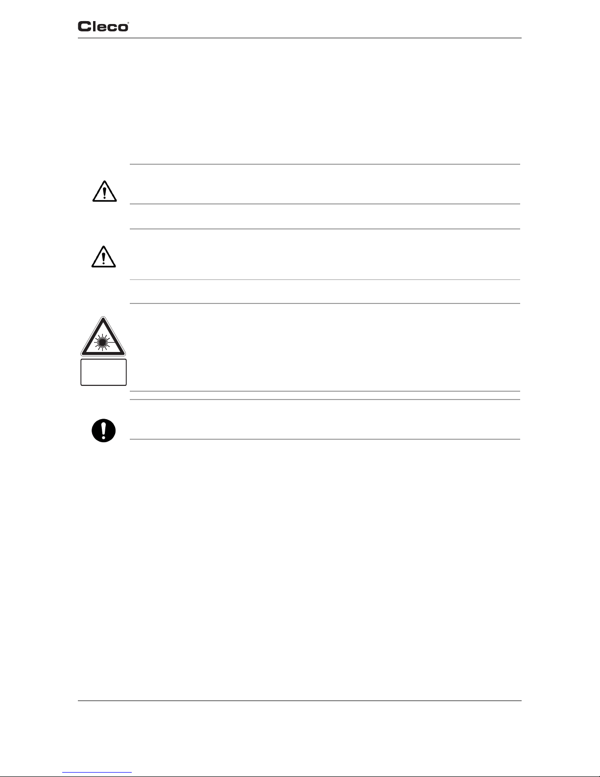
3.2 Operation and functional elements
This chapter describes operational and functional elements and their tasks in the order of their
respective item nos.
8
9
7
2
2
2
5
4
1 <F2>
2
6
3
2
Item Designation
1 Function keys <F1>, <F2>
2LED display
3 Start button
4 Reverse switch
5 IrDA (infrared interface port)
6 Set torque – stick-on marking foil
7 LED lights for fast location of the fastening position
8 Rechargeable battery
9 LCD display with information on torque, angle and status
10 Barcode scanner
11 Wireless module
11
10
1 <F1>

12 P1891E/EN 09/07 91b_1_5 en bedingt.fm, 24.09.2007
Scope of supply, transport and storage
2
3.2.1 Function keys
Left function key <F1>
• Confirm error message
➔ Press once.
Programmable: Depending on how the key is programmed, actions can be carried out by
pressing it briefly.
•Exit menu
➔ Press for two seconds.
Right function key <F1>
• Activate menu
➔ Press until the display shows the Main menu (for additional information, refer to 6.3 Operating
menu, page 24).
• Select functions, if menu is activated
➔ Press for two seconds. Alternatively, the start button can be pressed.
3.2.2 LED display
The LED display shows the respective operating status and the result of the last fastening
sequence (see 5.2 Operating status, page 19):
Software update
During Software Update, the actual programming process is indicated by rapid flashing alternat-
ing at irregular intervals between red and green.
LEDs Operating status Result
after screwing cycle
Steady light Green Active OK
Steady light Red Active NOK
Flashing light Green –
low frequency
Energy saver mode
Off Sleep
If Linking is selected on TMEB-200 / TMEC:
Flashing light Green –
high frequency
Active / Settings: Linking Linking OK
Flashing light Red Active / Settings: Linking Linking NOK
NOTE
Do not interrupt programming by removing the battery during this phase.

91b_1_5 en bedingt.fm, 24.09.2007 P1891E/EN 09/07 13
Scope of supply, transport and storage
2
3.2.3 Start button
The start button has 3 functions (Standard for TMEB-200 / TMEC):
• It activates the LED lighting.
➔ Press the start button halfway down and hold it.
• It starts the motor, the LED light goes out.
➔ Press the start button all the way down.
• It activates the barcode scanner—only for types of the 47BA...S series.
➔ Press the start button all the way down.
3.2.4 Reverse switch
The reverse switch changes the rotation direction of the 47BA:
Clockwise rotation – for screwing in screws
Press reverse switch as far as it will go.
When the start button is pressed Active appears on the LCD display.
Counterclockwise rotation – for loosening or screwing out screws
Press reverse switch as far as it will go.
When the start button is pressed Left appears on the LCD display.
3.2.5 IrDA interface port
The 47BA communicates with the TMEB-200 / TMEC controller or a PC (TMEB-COM) via the
IrDA interface port. For secure data transmission and for programming the 47BA, place the 47BA
in the tool holder with IrDA interface port, Order no. 935290. Data transmission is possible in the
Active, Energy saver mode and Standby operating modes, but not possible in Sleep
(see 5.2 Operating status, page 19).
3.2.6 Identification – set torque
To identify the set torque on the 47BA, glue the corresponding marking foil to the right and the left
of the LCD display.
NOTE
If the data transmission has been interrupted, the 47BA reports Synch error on the LCD display.
Replace the 47BA in the tool holder. The complete data transmission is acknowledged on the
display with Remain 512.
Order No.
935759
Order No.
935330

14 P1891E/EN 09/07 91b_1_5 en bedingt.fm, 24.09.2007
Scope of supply, transport and storage
2
3.2.7 LED lighting
LED lighting make it possible to quickly find the screw point.
3 different activation methods are possible. Define the method by programming
the TMEB-200 / TMEB-COM / TMEC correspondingly:
• Activation by pressing the start button halfway down (3.2.3 Start button, page 13).
• Time-controlled beginning at start
• You also have the option of disabling it.
The lighting distance is up to 4.7" (120 mm).
3.2.8 Rechargeable battery
For information on the battery, see
4.3 Charging the battery, page 17
4.4 Replacing the battery, page 18
10.4.1 Battery power supply, page 67.
3.2.9 LCD display
See 6 LCD display, page 21
3.2.10 Barcode scanner
For tools of the 47BA...S series, the built-in barcode scanner is a class 2 laser scanner with a
wavelength of 650 nm.
The barcode scanner reads one-dimensional linear barcodes:
Depending on how the TMEB-200 / TMEB-COM / TMEC is programmed, there are two different
operating modes:
Barcode as release for further rundowns
➔ Press the start button on the tool; this activates the barcode scanner.
The successful scan is acknowledged by an acoustic signal.
➔ Press the start button on the tool again; this starts the rundown.
If is necessary to read another barcode, proceed as follows.
CAUTION!
Eye injury from class 2 laser beam
➔ Do not look into the laser beam window when the laser is on.
➔ Repair any damage immediately.
Damage of the optical components can cause laser radiation.
➔ Modifications to the barcode scanner and procedures not outlined in these operating
instructions are strictly prohibited.
➔ Take defective devices out of operation immediately.
Scanning operation Acoustic signal
• Successful 50 ms long
•Faulty
• Not within 3 seconds
• Canceled by pressing the start button
3 times in rapid succession
LASER RADIATION
DO NOT LOOK INTO THE BEAM
CLASS 2 LASER
IN ACCORDANCE WITH
EN 60825-1:1994
P < 1mW;
λ = 630 nm

91b_1_5 en bedingt.fm, 24.09.2007 P1891E/EN 09/07 15
Scope of supply, transport and storage
2
Barcode not necessary as release for further rundowns
➔ From the Scanner tool menu, select Read barcode.
➔ Press the start button on the tool; this activates the barcode scanner.
The successful scan is acknowledged by an acoustic signal.
➔ Press the start button on the tool again; this starts the rundown.
Alternative: Assign the Read barcode function to the left function key <F1> on the tool.
➔ Press the left function key <F1> on the tool once.
➔ Press the start button on the tool again; this activates the barcode scanner.
Programming the barcode scanner is described in the programming manual of the TMEB-200 /
TMEB-COM / TMEC.
3.2.11 WLAN interface port
Tools of type 47BAW…/47BAX… are equipped with an IEEE 802.11b standard WLAN interface
port in addition to the IrDA interface port. The tool uses this WLAN interface port for continuous
communication with the controller. This interface port is used to transmit both the parameters and
the rundown results. Data transmission is possible in the Active, Energy saver mode and
Standby operating modes, but not possible in Sleep (see 5.2 Operating status, page 19). Programming and setting up the WLAN interface port are described in the programming manual of
the TMEB-200 / TMEB-COM / TMEC controller.
As the counterpart, an access point that complies with the IEEE 802.11b/g standard is required.
3.2.12 868 MHz interface port (EU)
Tools of the type 47BAR… have an 868 MHz interface port in addition to the IrDA interface port.
The tool uses this 868 MHz interface port for continuous communication with the controller. This
interface port is used to transmit both the parameters and the rundown results. Data transmission
is possible in the Active, Energy saver mode and Standby operating modes, but not possible in
Sleep (see 5.2 Operating status, page 19). Programming and setting up the 868 MHz interface
port are described in the programming manual of the TMEB-200 / TMEB-COM / TMEC controller.
The base station, Order no. 961300, is required as the remote station.
3.2.13 915 MHz interface port (NA)
Tools of the type 47BAF… have an 915 MHz interface port in addition to the IrDA interface port.
The tool uses this 915 MHz interface port for continuous communication with the controller. This
interface port is used to transmit both the parameters and the rundown results. Data transmission
is possible in the Active, Energy saver mode and Standby operating modes, but not possible in
Sleep (see 5.2 Operating status, page 19). Programming and setting up the 915 MHz interface
port are described in the programming manual of the TMEB-200 / TMEB-COM / TMEC controller.
The base station 961301 is required as the remote station.
NOTE
After the tool is switched on, it can take up to 25 seconds until the communication via WLAN is
active.
16 P1891E/EN 09/07 91b_1_5 en bedingt.fm, 24.09.2007
Scope of supply, transport and storage
2
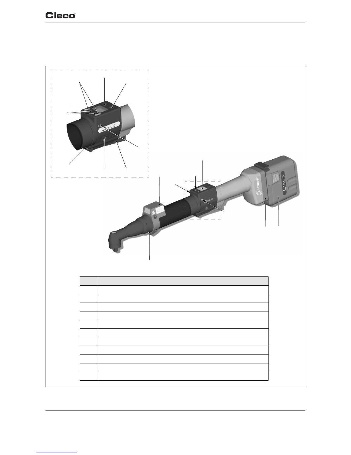
3.3 System overview – optional accessories
Overview EC tool_optional equipment
Alternatives
Item Designation
1 TMEB-200 / TMEC – Controller for electric nutrunner
2 Access point –
Order no. 543995 (NA)
Order no. 961323 (EU)
3 Tool series 47BA
4 Tool holder
Order no. 935290 – with IrDA interface, RS232 connection cable
Order no. 935395 – without IrDA interface, RS232 connection cable
5 Tool series 17BP
6 Tool holder
Order no. 935144 – with IrDA interface, RS232 connection cable
Order no. 935396 – without IrDA interface, RS232 connection cable
7 Interchangeable battery, Li-ion, 26 V – Order no. 935377
8 Battery charger, Li-ion, 26 V (110 – 230 VAC) – Order no. 935391
9 RS232 extension cable (IrDA)
Order no. 935154 – 9.84" (3 m)
Order no. 935155 – 19.7" (6 m)
Order no. 935157 – 32.8" (10 m)
10 TMEB-COM – Computer with PC software
11 Base station
Order no. 961301 – 915 MHz (NA)
Order no. 961300 – 868 MHz (EU)

91b_1_5 en bedingt.fm, 24.09.2007 P1891E/EN 09/07 17
Before initial operation
4
4 Before initial operation
The 47BA has been configured by Cooper Power Tools. A setting for your specific screw joint
needs must only be made with the TMEB-200 / TMEC controller or a PC by a qualified person.
For more information, refer to the TMEB-200 / TMEB-COM / TMEC programming manual.
4.1 Setting up tool holder
➔ Mount the tool holder on a stable base.
For tool holder with IrDA interface port:
➔ Select the location in such a way that no outside light shines onto the tool holder.
This can inhibit data transmission.
➔ Lay the connection cable in such a way that there is no danger that persons can trip.
4.2 Ambient conditions
4.3 Charging the battery
Charge fully before first use.
Battery is only partly charged when delivered.
➔ Fully charge before first use.
➔ Battery charging temperature: 5 °C to +45 °C (+41 °F to +113 °F)
➔ Follow the safety instructions printed on the battery and charger.
➔ Fully charge new batteries or those not used for a long time.
➔ Do not totally discharge the battery (< 17.5 V).
➔ Protect the battery from impact.
➔ Keep the charger and battery contacts clean and dry.
➔ Protect the battery from moisture.
➔ The battery can remain in the charger when not in use: the self-discharging is very low.
➔ Replace used batteries and recycle them (see 12 Disposal, page 71.)
Ambient temperature 0 °C (32 °F) to maximum +40° C (+104° F)
Humidity 0 to 80 %, not with dew
Working height up to 1000 m above sea level
WARNING!
Electrical shock, overheating or leakage of corrosive liquid from the battery can occur when
using incorrect chargers or batteries.
➔ Use only original CLECO batteries and chargers.
They are designed for use together.
NOTE
With proper use, the battery can be charged at least 800 (60% capacity) times.
Here, the following is important:
18 P1891E/EN 09/07 91b_1_5 en bedingt.fm, 24.09.2007
Before initial operation
4
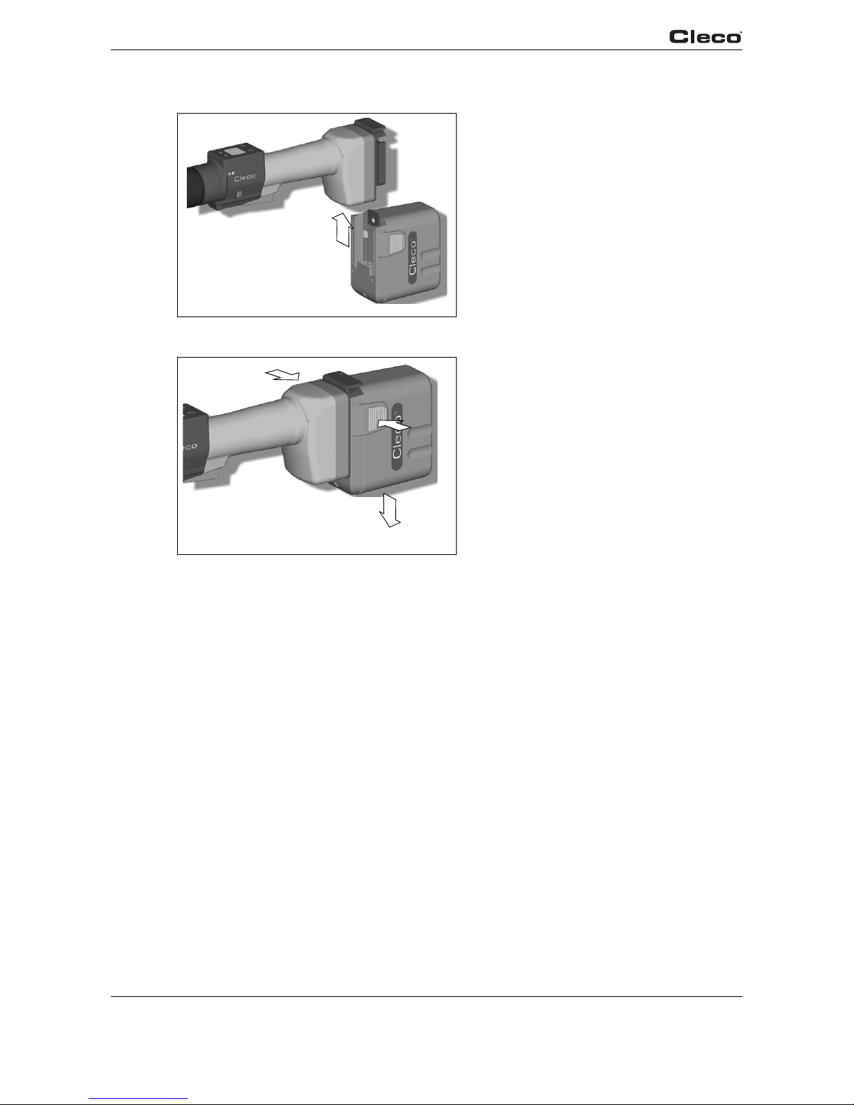
4.4 Replacing the battery
Fig. 4-1:
Fig. 4-2:
Inserting the battery
➔ Insert the battery into the tool guide
until the catches securely engage.
Removing the battery
➔ Press the catches together and pull the
battery out of the handle.
1.
2.

91b_1_5 en bedingt.fm, 24.09.2007 P1891E/EN 09/07 19
First Operation
5
5 First Operation
5.1 Carrying out the rundown
Make sure that the battery is securely installed before operating the 47BA. The 47BA is now
ready for use. After you press and release the start button, the LCD display reads Ready.
Types with wireless transmission continuously communicate with the controller. The tool automatically receives the parameters and, when the rundown is complete, automatically sends the
rundown results to the control system. Programming and setting up the wireless interface port
are described in the programming manual of the TMEB-200 / TMEB-COM / TMEC controller.
Types without wireless transmission must be placed in the tool holder when the rundown is complete. The rundown results are transmitted and shown under the Run screen menu item.
5.2 Operating status
The operating modes change in the following order.
The following functions are available depending on the display:
Operating
status
LED
display
LCD display Function
Active Steady light:
Red – Rundown NOK
Green – Rundown OK
On Screws
Data transmission
Automatic switch to the following after 1 minute idle time:
Energy
saver mode
Flashing light Green Off Data transmission
Automatic switch to the following after further 10 minutes:
Sleep Off Off Data transmission not
possible
Manual switch from Sleep to Active:
Press down start button and hold down for approx. 1 second.
To switch off the 47BA manually, pull out the battery.

20 P1891E/EN 09/07 91b_1_5 en bedingt.fm, 24.09.2007
First Operation
5

91c_LCD en bedingt.fm, 24.09.2007 P1891E/EN 09/07 21
LCD display
6
6 LCD display
The LCD display on the tool is divided into the result display, status display, operating menu and
system error messages.
6.1 Result display
First line – result:
The status is displayed in alternation with the Application being used.
The LCD display consists of a three lines, each with 6 characters,
to display the status, torque and angle. The result display is updated after the
rundown ends.
OK Result is OK
NOK Result is not OK
OFF Torque transducer offset error
CAL Torque transducer calibration error
ENC Angle encoder error
IP Current overload in output section
IIT Requested motor output is too high
TMAX Maximum fastening time exceeded
RC Rundown canceled by disabled start signal
TS Depth sensor signal was enabled at start or
was subsequently disabled during the rundown (only for 17BP series)
Tq< Torque too low
Tq> Torque too high
A< Angle too low
A> Angle too high
Error Error occurred
Second line – Shut-off torque in Nm:
T Final torque
Third line – Shut-off angle in degrees:
A Final angle
For types with wireless transmission, an interrupted data connection to the
TMEB-200 / TMEB-COM / TMEC is indicated by the symbol at the top right of
the LCD display.
OK
T 12.00
A 100
OK
T 12.00
A 100

22 P1891E/EN 09/07 91c_LCD en bedingt.fm, 24.09.2007
LCD display
6
6.2 Status display
The status display is divided into the "Standard" and "Linking" modes. "Standard" is selected if
"Linking" is not enabled on the TMEB-200 / TMEB-COM / TMEC (see Advanced Applica-
tion Builder\Linking). The application is selected at the Run Screen or via the App. selection inputs.
No other status messages take priority.
The tool is ready.
Number of remaining rundowns that can still be carried out until the rundown
data memory is full and the rundown data have to be transmitted to the
TMEB-200 / TMEB-COM / TMEC.
Emergency strategy active. Is displayed if emergency strategy is currently active
and with that no communication with TMEB-200/TMEB-COM/TMEC is necessary. On Tool are the latest 512 rundown results stored.
All fastening sequences have been completed.
➔ Synchronize the tool with the TMEB-200 / TMEB-COM / TMEC.
No fastening sequences have been initialized.
➔ Synchronize the tool with the TMEB-200 / TMEB-COM / TMEC.
No fastening sequence parameters have been set.
➔ Check the Application and Tightening group selected on the TMEB-200 /
TMEB-COM / TMEC to determine whether the tool settings and process
programming have been carried out.
Application locked.
➔ Synchronize the tool with the TMEB-200 / TMEB-COM / TMEC.
Reject Release active.
The tool has been programmed in Advanced Application
Builder\Reject Release.
➔ Depending on the programming, unlock the tool via the external input
NOK release or Release on Backoff. To unlock via the external input NOK
release, set the external input and synchronize it with the TMEB-200 /
TMEB-COM / TMEC.
Ready
Remain
512
Emerge
Strate
Job
comple
Sync
No
Job
Sync
Parame
not
set
App
locked
Sync
Reject
Releas
Sync

91c_LCD en bedingt.fm, 24.09.2007 P1891E/EN 09/07 23
LCD display
6
Additional messages in "Linking" mode
Error in last data synchronization with the TMEB-200 / TMEB-COM / TMEC.
➔ Synchronize the tool with the TMEB-200 / TMEB-COM / TMEC again.
Tool has not yet been synchronized with a TMEB-200 / TMEB-COM / TMEC.
➔ Carry out initial synchronization of the tool with the TMEB-200 /
TMEB-COM / TMEC.
The Tool Enable input is missing.
➔ Set the Tool Enable input.
➔ Synchronize the tool with the TMEB-200 / TMEB-COM / TMEC.
This message can appear only if External Tool Enable has been activated
in Advanced Application Builder\System settings.
Tool disabled since no valid barcode data has been set.
➔ Send the barcode to the TMEB-200 / TMEB-COM / TMEC.
➔ Synchronize the tool with the TMEB-200 / TMEB-COM / TMEC once
again.
First line: The next position to be fastened.
Second line: Number of positions.
Third line: Number of repetitions at this position in case of an NOK rundown.
Linking has been cancelled without a batch result.
Not all of the positions in the tightening group have been programmed.
➔ Check the Application and Tightening group selected on the TMEB-200 /
TMEB-COM / TMEC to determine whether the tool settings and process
programming have been carried out.
Linking result OK.
Linking result NOK.
Sync
Error
Tool
not
Init
Input
Enable
Missin
Need
Part
ID
N.Pos1
of 3
Rpl 0
Linkin
No
Result
Linkin
OK
Linkin
NOK

24 P1891E/EN 09/07 91c_LCD en bedingt.fm, 24.09.2007
LCD display
6
6.3 Operating menu
6.3.1 General
The operating menu on the tool is divided into a main menu and submenus. You can navigate
through the menus using the two function keys below the LCD display. In the following description, <F1> is used for the left function key and <F2> is used for the right function key. The menu
is activated by pressing the right function key, <F2>. The menus can be disabled by configuring
appropriate parameter in the controller.
Basic functions:
➔ <F2>: Activate main menu.
➔ <F1>: Go to previous menu item.
➔ <F2>: Go to next menu item.
➔ Press <F1> longer than 2 seconds
to go to the next higher menu level. If the main menu is activated, the system goes into production mode.
➔ Press the start button or <F2> longer than 2 seconds
to activated the highlighted item or execute the highlighted action. Actions that start the tool
can be carried out only by pressing the start button.
➔ If the menu is enabled, no rundowns are possible.
➔ Each submenu has an entry for Back.
Linking disabled.
➔ Synchronize the tool with the TMEB-200 / TMEB-COM / TMEC.
Enables the main menu.
Linkin
locked
Sync
Back

91c_LCD en bedingt.fm, 24.09.2007 P1891E/EN 09/07 25
LCD display
6
6.3.2 Structure
Main
Administration
Administration
Diagnostics Date / Time
Set position Counter display
Scanner Serial number
RF settings Software version
Back Emergency strategy
Back
Diagnostics
TQ calibration
TQ measurement
Angle encoder
Voltages
Speed
Back
Set position
Next position
Reset linking
Back
Scanner
Read barcode
Back
WLAN wireless transmission
47BAW…/ 47BAX… series
Wireless module version
MAC address
IP address
Subnet mask
Gateway
SSID
Signal strength
Back
868 / 915 MHz wireless transmission
47BAR…/ 47BAF… series
Wireless module version
Channel
Network ID
Tool ID
Power
Back

26 P1891E/EN 09/07 91c_LCD en bedingt.fm, 24.09.2007
LCD display
6
6.3.3 Main menu
6.3.4 Administration submenu
Administration – General items such as Date/Time, Counter display, etc.
Diagnostics – Diagnostic functions for the tool.
Position – Selects the position to be used next.
Scanner – Deletes a previously read barcode and activates a new read cycle.
RF settings – Displays the settings used for wireless transmission.
Date/Time
Displays the tool system time.
The system time can be displayed in US or European format.
➔ Refer to "Setting the system time on the TMEB-200 / TMEB-COM / TMEC
under Administration\Date\Time.
Counter display
The tool counter display is incremented after each rundown throughout the
service life of the tool.
➔ Refer to "Counter display on the TMEB-200 / TMEB-COM / TMEC under
Diagnostics\Tool\Tool Memory.
Serial number
Displays the tool serial number.
➔ Refer to "Serial number on the TMEB-200 / TMEB-COM / TMEC under
Tool or Diagnostics\Tool\Tool Memory.
>Main
Admini
strati
>Main
Diag-
nostic
>Main
Posi-
tion
>Main
Scan-
ner
>Main
RF-SET
Time
07:47
30.09
Counte
99
999999
S/N
000000
245

91c_LCD en bedingt.fm, 24.09.2007 P1891E/EN 09/07 27
LCD display
6
Software version on controller board
Displays the installed software version.
Software version on servo
Displays the installed software version.Displays the installed software version.
NOTE
The emergency strategy can activated only if Emergency Strategy has been enabled on the
TMEB-200 / TMEB-COM / TMEC under Advanced Application
Builder\System settings.
Emergency strategy disabled.
➔ Enable the emergency strategy on the TMEB-200 / TMEB-COM / TMEC
under Advanced Application Builder\System settings\Enable emergency strategy.
Emergency strategy off.
If it has been enabled on the TMEB-200 / TMEB-COM / TMEC under Advanced
Application Builder\System settings\Enable emergency strategy,
you can switch the emergency strategy on and off using the tool start button or
by pressing <F2> for 2 seconds. The Emergency strategy is disabled automatically when the tool links to the TMEB-200 / TMEB-COM / TMEC
Emergency strategy on.
If the emergency strategy is enabled and Linking is disabled, the fastening
parameters of the last selected Application are used. For Linking operating
mode, all steps are used with the corresponding parameters of the last selected
Tightening Group.
The memory of the tool stores data from up to 512 rundowns. If more rundowns
than this are executed while the Emergency strategy is active, the oldest results
are always discarded once 512 rundowns have been recorded.
Emergency strategy active. Is displayed during fastening.
Ver s.
V1.00.
00
Servo
V:T108
N00015
Emerge
Strate
locked
Emerge
Strate
Off
Emerge
Strate
On
Emerge
Active

28 P1891E/EN 09/07 91c_LCD en bedingt.fm, 24.09.2007
LCD display
6
6.3.5 Diagnostics submenu
TQ calibration
This test function cyclically recalibrates the system with the values used immediately before the start of a rundown. For this, the tool must not be tensioned!
First line: Calibration test and status.
Second line: TQ calibration voltage.
Third line: Offset voltage. If a value lies outside the tolerance range, the corresponding error is displayed.
TQ measurement
In this test function, after the start button is pressed, the same calibration is
carried out as immediately before the start of a rundown. For this, the tool must
not be tensioned!
Then, the tool starts with speed "0". The torque is continuously measured and
displayed until the start button is released.
Second line: Current torque.
Third line: Peak value, highest value since the start button was pressed.
Angle encoder
The start button starts the tool at 30% of the maximum speed. After one revolution of the output shaft (nominal angle 360°), measured with the resolver, the tool
is stopped. During a fixed dwell time of 200 ms, any further angle pulses occurring are traced. The total result is shown as Actual Angle. If the test run is not terminated by a monitoring criterion and the batch result is greater than or equal to
360 degrees, it is evaluated and displayed as OK. Monitoring criteria are the
torque and a monitoring time.
If the torque exceeds 15 % of the calibration value (even during the dwell time),
or if the monitoring time of 4 seconds expires, the test run is terminated with a
TQ> or TMAX result. However, you specifically need to check whether the output
shaft has actually turned by the value indicated (e. g. by placing a mark on the
spindle). If the angle reached by the output shaft does not agree with the value
displayed, either the angle factor has been entered incorrectly or the resolver is
defective.
Voltag es
Second line: Current battery voltage. To ensure high utilization potential, this
voltage is monitored continuously during fastening operation. If the voltage drops
below limit, a warning output on the tool.
Third line: Programmed value. This can be changed using the TMEB-200 /
TMEB-COM / TMEC under Tool.
Cal OK
K 1.11
O 0.00
Value Rated
value
Tolerance
Calibration offset 0 V ± 45 mV
TQ calibration voltage: 1.122 V ± 32 mV
Torque
T 5.57
T 8.23
Angle
A 360
OK
Voltag e
V26.00
L18.00

91c_LCD en bedingt.fm, 24.09.2007 P1891E/EN 09/07 29
LCD display
6
6.3.6 Set position submenu – only with Linking enabled
6.3.7 Scanner submenu – only for types of the 47BA...S series
Speed
The start button starts the tool at the maximum speed.
Second line: Current output shaft speed.
Third line: Current torque.
Rotational speed measurement is based on the angle information of the resolver.
If you release the start button, the tool stops. As a safety function the torque is
monitored by the tool transducer. If it exceeds 15 % of its calibrated value, the
speed measurement is terminated.
Selects the position to be used next.
You can skip the position.
You can select the position to be used next using the function keys:
➔ <F1>: Activate the previous position.
➔ <F2>: Activate the next position.
➔ Press the start button or <F2> longer than 2 seconds
to accept the select and display the next menu item.
➔ Press <F1> longer than 2 seconds
to delete the selection and exit the menu.
Reset linking to position 1. The operator could terminate linking.
Scanner – Deletes a previously read barcode and activates a new read cycle.
➔ Press the start button or <F2> longer than 2 seconds.
Speed
Rpm466
T 0.02
<Posit
Change
Positi
Select
Positi
2/6
>Posit
Reset
Positi
<Scann
Activa
Scanne

30 P1891E/EN 09/07 91c_LCD en bedingt.fm, 24.09.2007
LCD display
6
6.3.8 WLAN wireless transmission submenu –
only for types of the 47BAW… / 47BAX… series
The WLAN RF settings submenu shows the settings being used.
If no actions are carried out, the menu is automatically exited after 60 seconds.
Programming the RF settings for WLAN data transmission is described in the programming
manual of the TMEB-200 / TMEB-COM / TMEC.
Displays the installed software version of the wireless module.
MAC address display
IP address display
Subnet display
Gateway display
SSID display. Only the first 12 characters are displayed.
When the start button is pressed, the current wireless signals are displayed.
17BPW… / 47BAW…:
N = Ratio of signal strength to ambient noise (dB)
S = Signal strength (dBm)
L = Ambient noise (dBm)
17BPX… / 47BAX…:
N = Signal strength (%)
S = Signal strength (dBm)
Ver sio
#27173
Dec 1
MAC
00302e
e162f8
IP 010
.122.0
77.110
Sub255
.255.2
40.0
Gat010
122.0
61.001
SSID
CPT
N: 34
S: -60
L: -94

91c_LCD en bedingt.fm, 24.09.2007 P1891E/EN 09/07 31
LCD display
6
6.3.9 868/915 MHz wireless transmission submenu –
only for types of the 47BAR…, 47BAF… series
The 868/915 MHz RF settings submenu shows the settings being used. If no actions are carried
out, the menu is automatically exited after 60 seconds.
Programming the RF settings is described in the TMEB-200 / TMEB-COM / TMEC programming
manual.
Displays the installed software version of the wireless module.
Displays the radio channel being used and allows you to configure settings.
With 868 MHz, you can select channel 1 – 3.
With 915 MHz, you can select channel 1 – 8.
➔ <F1>: Activate a lower channel.
➔ <F2>: Activate a higher channel.
➔ Press the start button or <F2> longer than 2 seconds
to accept the select and display the next menu item.
➔ Press <F1> longer than 2 seconds
to delete the selection and exit the menu.
NOTE
The channel must match the set channel of the base station.
Defines the network identification. You can operate no more than 4 tools per
network ID.
➔ <F1>: Activate a lower network ID.
➔ <F2>: Activate a higher network ID.
➔ Press the start button or <F2> longer than 2 seconds
to accept the select and display the next menu item.
➔ Press <F1> longer than 2 seconds
to delete the selection and exit the menu.
NOTE
The network ID must match the set network ID of the base station.
Ver sio
B868
MC-tin
Chan-
nel
1/3
Networ
ID
1/16
32 P1891E/EN 09/07 91c_LCD en bedingt.fm, 24.09.2007
LCD display
6
6.4 System error messages
Displays the tool ID and allows you to configure settings.
You can select a tool ID from 1 – 4.
➔ <F1>: Activate a lower network ID.
➔ <F2>: Activate a higher network ID.
➔ Press the start button or <F2> longer than 2 seconds
to accept the select and display the next menu item.
➔ Press <F1> longer than 2 seconds
to delete the selection and exit the menu.
NOTE
Each tool can be used only once for each base station.
Displays the transmission power and allows you to configure settings.
➔ <F1>: Activate a lower transmission power.
➔ <F2>: Activate a higher transmission power.
➔ Press the start button or <F2> longer than 2 seconds
to accept the select and display the next menu item.
➔ Press <F1> longer than 2 seconds
to delete the selection and exit the menu.
For 868 MHz, the maximum transmission power depends on the selected channel. If channel 1 is selected, you can choose between 1, 5, 10, and 25 mW for
the transmission power. If channel 2 or 3 is selected, you can choose either 1 or
5 mW for the transmission power. For 915 MHz, you can choose between 1, 5,
10, and 25 mW.
➔ Press the start button or <F2> longer than 2 seconds
to accept the select and display the next menu item.
➔ Press <F1> longer than 2 seconds
to delete the selection and exit the menu.
NOTE
If a error is displayed, fastening is disabled until the error is acknowledged with the left-hand button on the tool. In the event of serious hardware errors, the tool is not enabled again even after
the error is acknowledged, and must be returned to the manufacturer for repair.
Initialization error in tool servo.
➔ Remove the battery and then re-insert it. If this does not help:
➔ Return tool to manufacturer for repair.
Tool
ID
1/4
Power
25 mW
Servo
Error
Init

91c_LCD en bedingt.fm, 24.09.2007 P1891E/EN 09/07 33
LCD display
6
Speed specification from the measuring board to the servo is faulty.
➔ Remove the battery and then re-insert it. If this does not help:
➔ Return tool to manufacturer for repair.
Too much power is being demanded from the tool.
➔ Switch the tool off for a time so that it can cool down.
➔ Increase the cycle time, reduce the fastening time or the torque.
The servo's current sensor is detecting a current offset error.
➔ Return tool to manufacturer for repair.
Collective servo error caused by hardware.
➔ Return tool to manufacturer for repair.
The current setpoint has been exceeded.
There may be a short circuit.
➔ Return tool to manufacturer for repair.
The servo has overheated.
➔ Switch the tool off for a time so that it can cool down.
➔ Increase the cycle time, reduce the fastening time or the torque.
The tool motor has overheated.
➔ Switch the tool off for a time so that the motor can cool down.
➔ Increase the cycle time, reduce the fastening time or the torque.
Operating voltage is outside the admissible range.
➔ Change the battery. If this does not help:
➔ Return tool to manufacturer for repair.
Current at servo output stage is too high.
There may be a short circuit.
➔ Return tool to manufacturer for repair.
Tool angle encoder is sending incorrect signals to the servo amplifier.
➔ Return tool to manufacturer for repair.
Servo
Error
PWM
Servo
Error
IIT
Servo
Error
IOFF
Servo
Error
Other
Servo
Error
IP
Servo
Error
Tem p >
Servo
Error
Tem pM>
Servo
Error
Voltag
Servo
Error
Curr>
Servo
Error
Angle

34 P1891E/EN 09/07 91c_LCD en bedingt.fm, 24.09.2007
LCD display
6
Warns that battery is running low.
➔ Recharge battery or replace it with one that is already charged.
The rundown counter could not be read or written to.
➔ Return tool to manufacturer for repair.
Tool memory could not be read.
➔ Return tool to manufacturer for repair.
Two-stage start button defective.
➔ Return tool to manufacturer for repair.
Transducer reference voltage error.
➔ Return tool to manufacturer for repair.
Transducer calibration voltage error.
Tool was not discharged at time of calibration.
➔ Allow tool to discharge and try again. If this does not help:
➔ Return tool to manufacturer for repair.
Transducer offset voltage error.
Tool was not discharged at time of calibration.
➔ Allow tool to discharge and try again. If this does not help:
➔ Return tool to manufacturer for repair.
General collective error.
➔ Return tool to manufacturer for repair.
Low
voltag
warnin
Tool
Error
Counte
Tool
Error
Ident
Tool
Error
Start
Transd
Ref.V.
Error
Trans
CAL
Error
Trans
Off
Error
Unknow
Error

91d_Wartung en.fm, 24.09.2007 P1891E/EN 09/07 35
Maintenance
7
7 Maintenance
7.1 Cleaning instructions
For tools with a built-in barcode scanner, the window must be free of dirt.
➔ Clean it regularly—or immediately, if it becomes dirty—using a damp cloth and a conventional
window cleaner. Do not use acetone for cleaning. A dirty window may make it impossible to
read barcodes.

36 P1891E/EN 09/07 91d_ Wartung en.fm, 24.09.2007
Maintenance
7
7.2 Service schedule
Regular maintenance reduces operating faults, repair costs and downtime. In addition to the following service plan, implement a safety-related maintenance program that takes the local regulations for repair and maintenance for all operating phases of the tool into account.
CAUTION!
Danger of injury due to unintentional activation
– before service - disconnect the 47BA from the battery.
After
… fastening cycles
1)
)
1) For the number of fastening cycles, refer to the counter display in 6.3.4 Administration submenu, page 26
Actions
100.000
➔ Check to ensure the battery adapter, scanner and radio
adapter are seated securely.
➔ Check the tool and battery for damage.
➔ Check to ensure scanner window is transparent.
➔ Check to ensure battery contacts are clean.
➔ Check to ensure battery charger is clean.
➔ Check the gearing and angle head for leaks
500,000
➔ Use grease-dissolving agent to clean the angle head
and gearing components and then regrease, see
9.4 Gear + angle attachment, page 54.
9.5 Angle attachment 935313, page 56
9.6 Angle attachment 525943, page 58
➔ Check the angle head and gearing components for wear
and replace if necessary.
➔ Check battery guide, locking mechanism and contacts for
wear and replace if necessary.
1 million
➔ Use grease-dissolving agent to clean the angle head
and gearing components and then regrease, see
9.4 Gear + angle attachment, page 54.
9.5 Angle attachment 935313, page 56
9.6 Angle attachment 525943, page 58
➔ Check the angle head and gearing components for wear
and replace if necessary.
➔ Check battery guide, locking mechanism and contacts for
wear and replace if necessary.
➔ Recommendation: Recalibrate tool, see 11.1 Recalibra-
tion, page 71.
2.5 million
➔ General overhaul. Send it to Cooper Power Tools.

91d_Wartung en.fm, 24.09.2007 P1891E/EN 09/07 37
Maintenance
7
7.3 Lubricants
For smooth function and a long service life, use of the correct grease types according to the table
is essential.
Grease lubricants according to DIN51502 /ISO3498
7.4 Disassembling gear
NOTE
If the 47BA is opened, the warranty is voided. Only specialized technicians should be allowed to
open the gear for maintenance reasons.
Order no. Packing
unit
[ kg ]
DIN
51502
Nye
Lubricants,
Inc.
Dow
Corning
912554 15 G-POH
Aralub
FD00
Energrease
HTO
GA 0 EP
Expa 0
Mobilplex 44 –
Spec ial
Gear
H
–
933027 1 KP1K – – – –
Microlube
GL 261
––
912724 1 K-F2K – –
elf Multi
MoS
2
– UNIMOLY GL 82 –
Molykote
BR 2
541444 0.8 – – – – – – –
Rheolube
363AX-1
➔
Carefully tension the 47BA at the contact faces in a vise with plastic jaws
(max. 15 mm high).
➔ Release the Z by turning it counter-
clockwise.
Hook wrench, order no. 933336.
➔ Completely remove angle attachment.
➔ Pull gear completely off angle attach-
ment.
Z

38 P1891E/EN 09/07 91d_ Wartung en.fm, 24.09.2007
Maintenance
7
7.5 Removing angle attachment 935313
1.
2.
3. 4.
Index: See 9 Spare parts, page 47; 9.8 Fixture order list for angle attachment 935313, page 62
15 ohne 22 / 23
24
(29)
C2
25
F
1/2
D5
D4
(29)
C2
D5
D4
(29)
D5
D3
D2
D1
D5
91d_Wartung en.fm, 24.09.2007 P1891E/EN 09/07 39
Maintenance
7
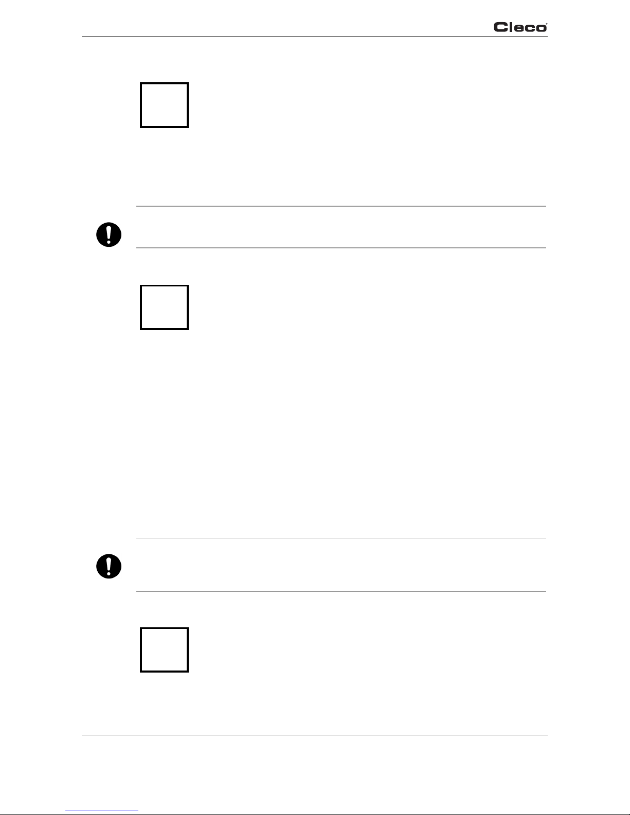
7.6 Installing angle attachment 935313
Drive spindle
Bevel gear spindle
1.
2.
3.
4.
Index: See 9 Spare parts, page 47; 9.8 Fixture order list for angle attachment 935313, page 62
31
30
A2
A1
A3
(29)
A2
30
31
27
28
B2
B1
26
(29)
26
(29)

40 P1891E/EN 09/07 91d_ Wartung en.fm, 24.09.2007
Maintenance
7
Bevel gear and drive spindle in angle attachment
5. 6.
Index: See 9 Spare parts, page 47; 9.8 Fixture order list for angle attachment 935313, page 62
36
C3
B1
26
27
(29)
28
C2
F
1/2
OFF
18 22 Nm
13,3 16,3 lbf.ft
Loctite #242
OFF
10 - 14 Nm
7,4 - 10,4 lbf.ft
37
38
39
36
24
25
E
1/2

91e_Trouble shooting en bedingt.fm, 24.09.2007 P1891E/EN 09/07 41
Troubleshooting
8
8 Troubleshooting
Problem Possible cause Action
General – Tool
Tool does not start if
reverse switch is active.
Backoff speed parameter is set to 0 rpm.
¾ Adjust the backoff speed value in the Standard
Application Builder screen of the controller.
Tool light not active. Deactivated by param-
eter setting.
¾ Adjust the parameter for Tool light in the
Advanced Application Builder/System Settings
screen of the controller.
Operating menu of tool
not, or only partly,
enabled.
Disabled by parameter
setting.
¾ Activate the Enable Tool menu parameter in
the Advanced Application Builder/System Set-
tings screen of the controller.
Free speed parameter
value is not reached.
Battery voltage is too
low.
¾ Use a fully charged battery.
Could not reach the
expected number of
rundowns with one
battery charge.
Battery is not fully
charged.
¾ Use only fully charged batteries.
Low voltage warning is
not set to minimum
value.
¾ In the Tool Setup screen of the controller, set
the value for Low Level to 17.5 Volts.
During tightening
sequence, high torque
is required, for example
with coated screws.
¾ If high torque is required for a longer period of
time, e.g. for several turns, then the number of
rundowns with one battery charge is significantly reduced.
Battery has already
cycled too often.
¾ After 500 charge cycles the capacity is reduced
to about 80%.
Problem Possible cause Action
Infrared data communication between controller and tool
No infrared data
communication
between controller and
tool.
Wrong port is selected
for connection with the
controller.
¾ Check the port settings for infrared (IRDA)
communication in the Communication/Tool
screen of the controller.
Note: If the settings are changed, it is necessary
to press Accept <F1> in order to apply the settings.
¾ Check that the tool holder is connected to
selected port.
Selected port is used
for serial data transmission.
¾ In the Communication/Data Transmission
screen of the controller, check whether serial
data transmission is enabled (the protocol is
set to anything except NONE), and whether
the same port is being used. If so, select a dif-
ferent port or disable serial data transmission.
Check all available tools as necessary. The
same port cannot be used for serial data trans-
mission and infrared data communication with
the tool.

42 P1891E/EN 09/07 91e_Trouble shooting en bedingt.fm, 24.09.2007
Troubleshooting
8
Problem Possible cause Action
WLAN data communication between controller and tool
No WLAN
communication
between controller and
tool.
IP address of tool is not
entered correctly on the
controller.
¾ Check in the Communication/Tool screen of
the controller that the IP address of the tool is
entered in the RF Tool IP field. The IP address
of the tool is displayed on the tool in the WLAN
RF settings submenu.
Note: If the settings are changed, it is necessary
to press Accept <F1> in order to apply the settings.
Tool is not configured
with correct WLAN
parameter values.
¾ Configure the WLAN settings of the tool in the
Communication/Tool screen of the controller
via infrared communication.
WLAN network settings of the controller
and the access point
differ.
¾ In the Communication/Tool screen of the con-
troller, check that the settings of the access
point match the wireless network settings (Net-
work name, Security, Network key).
MAC address filter of
the access point is
active.
¾ Add the MAC address of the tool to the
address list of the access point. The MAC
address of the tool is displayed on the corre-
sponding label above the battery, and in the
WLAN RF settings submenu.
A firewall blocks port
4001.
¾ Reconfigure the firewall so that the specific IP/
MAC address of the tool can use port 4001.
The RF channel at the
access point is out of
the tool-supported
range.
¾ Change the channel setting of the access point
to a channel between 1 and 11.
Tool is already
assigned to a different
controller.
¾ Check whether any other controller has
already established a connection to this tool.
That means another controller use same IP
address.
WLAN communication
partly interrupted.
Distance between
access point and tool is
too great.
¾ Check the signal strength in the WLAN RF set-
tings submenu of the tool. For stable communi-
cation, the first value (N) should be greater
than 15. If the value is less than 15, move the
access point closer to the tool.
Tool is also assigned to
a different controller.
¾ Check whether this tool (IP address) is
assigned to any other controller. If so, delete
the assignment on the other controller. A tool
can only be assigned to one controller.
Too much traffic on the
wireless network.
¾ Reduce traffic on the wireless network.
Deactivate torque plot data transmission.

91e_Trouble shooting en bedingt.fm, 24.09.2007 P1891E/EN 09/07 43
Troubleshooting
8
Problem Possible cause Action
868 MHz data communication between controller and tool
No serial communication is possible
between the controller
and the base station.
(Error displayed after
Accept <F1> is pressed
in Communication/
Tool .)
Wrong serial cable is
used.
¾ Use a null modem cable (crossed).
Wrong port is selected
for connection with the
controller.
¾ In the Communication/Tool screen of the con-
troller, check the port settings for RF Serial.
Note: If the settings are changed, it is necessary
to press Accept <F1> in order to apply the settings.
¾ Check that the serial cable is connected to the
selected port.
Selected port is used
for serial data transmission.
¾ In the Communication/Data Transmission
screen of the controller, check whether serial
data transmission is enabled (the protocol is
set to anything except NONE), and whether
the same port is being used.
¾ If so, select a different port or disable serial
data transmission.
¾ Check all available tools as necessary. The
same port cannot be used for serial data trans-
mission and data communication with base
station tool.
Power outlet not active.
¾ Check the voltage at the outlet socket where
the base station is plugged in for power supply.

44 P1891E/EN 09/07 91e_Trouble shooting en bedingt.fm, 24.09.2007
Troubleshooting
8
No Ethernet communication is possible
between the controller
and the base station.
(Error displayed after
Accept <F1>) is
pressed in Communi-
cation/Tool.)
Wrong Ethernet cable
is used.
¾ A crossover cable is required if the base sta-
tion is directly connected to the controller. If the
base station is connected to a switch, a stan-
dard patch cable is required.
IP address of the base
station is not entered
correctly on the controller.
¾ In the Communication/Tool screen of the con-
troller, check that the IP address of the base
station is entered in the RF Base station field. If
the IP address of the base station is unknown
use the Network Enabler Administrator pro-
gram, which is included with each base station.
Note: If the settings are changed, it is necessary
to press Accept <F1> in order to apply the settings.
IP address and subnet
mask are not in the
same range.
Without network administration, it is necessary for
the IP address and subnet mask of the controller
to be in the same range as those of the base station.
¾ Enter the same subnet mask for both IP
addresses and use the same first three num-
bers for the IP addresses on both the controller
and base station.
E.g.:
IP address controller: 192.168.1.xxx
IP address base station: 192.168.1.xxx
Subnet mask: 255.255.255.000
A firewall blocks port
4001.
¾ Reconfigure the firewall so that the specific IP/
MAC address of the tool can use port 4001.
Base station is already
connected to a different
controller.
¾ Check whether any other controller has
already used the same IP address for RF com-
munication (RF Base station).
Power outlet not active.
¾ Check the voltage at the outlet socket where
the base station is plugged in for power supply.
No 868 MHz data communication is possible
between controller and
tool.
Settings are not configured correctly.
¾ In the Communication/Tool screen of the con-
troller, check that RF settings of the base sta-
tion correspond to the settings of the tool,
which are displayed in the 868MHz RF settings
submenu of the tool. The settings for Channel,
Network ID and Tool ID must match.
Distance between base
station and tool is too
great.
If channel 1 is selected, the distance can be up to
98.4 ft (30 m). If channel 2 or 3 is selected, the distance can be up to 32.8 ft (10 m).
¾ Increase output power on base station and on
the tool, or move the base station closer to the
tool.
Problem Possible cause Action
868 MHz data communication between controller and tool

91e_Trouble shooting en bedingt.fm, 24.09.2007 P1891E/EN 09/07 45
Troubleshooting
8
RF communication is
partly interrupted.
Distance between base
station and tool is too
great.
If channel 1 is selected, the distance can be up to
30 m. If channel 2 or 3 is selected, the distance
can be up to 10 m.
¾ Move the tool close to the base station to
check whether communication is successful. If
so, increase output power on base station and
on the tool, or move the base station closer to
the tool.
Output power is too
low.
¾ Increase the output power of the base station
and of the tool. If channel 1 is selected, you
can choose up to 25 mW for the output power.
If channel 2 or 3 is selected, you can choose 1
mW for the output power of the base station
and 5 mW for the output power of the tool.
Too much traffic on the
same channel.
¾ Reduce traffic on the wireless network. Deacti-
vate torque plot data transmission.
Too many tools on the
same channel.
¾ Use different channels for different base sta-
tions.
Other 868 MHz devices
on the same frequency.
¾ Use a different channel.
Distance for RF communication is too short
Antenna of the base
station is not tightened
securely.
¾ Manually tighten the base station antenna.
Output power is too
low.
¾ Increase the output power of both the base sta-
tion and the tool.If channel 1 is selected, you
can choose up to 25 mW for the output power.
If channel 2 or 3 is selected, you can choose 1
mW for the output power of base station and 5
mW for the output power of the tool.
Location of the base
station bad.
¾ Move the base station to a location where
there is an unobstructed line of view between
the base station and the tool.
Problem Possible cause Action
Barcode scanner on tool
Barcode scanner does
not activate when the
start switch is pressed.
Parameter for Part-ID is
not set to Enable Interlocked.
¾ In the Communication/Part-ID screen of the
controller, check that the Enable parameter is
set to Enable Interlocked.
Barcode has already
been read.
¾ Activate a further read cycle in the scanner
submenu.
¾ Press the left function key on the tool in order
to activate another read cycle.
Note: Only available if the parameter for <F1> button on Tool is set to Read barcode in the
Advanced Application Builder / System Settings
screen of the controller.
Problem Possible cause Action
868 MHz data communication between controller and tool

46 P1891E/EN 09/07 91e_Trouble shooting en bedingt.fm, 24.09.2007
Troubleshooting
8
Barcode is not read. Barcode scanner win-
dow is not clean.
¾ Clean the window by using a damp cloth and a
conventional window cleaner.
Barcode type is disabled by parameter setting.
¾ In the Communication/Part-ID screen, check
that parameter Barcode Type is set to the
appropriate barcode type.
Problem Possible cause Action
Barcode scanner on tool

91f_Ersatzteile en.fm, 24.09.2007 P1891E/EN 09/07 47
Spare parts
9
9 Spare parts
Note
Use only original CLECO spare parts. Failure to comply can result in reduced power and
increased service requirements. If spare parts not manufactured by us are installed, the tool
manufacturer is entitled to deny any warranty claims.
48 P1891E/EN 09/07 91f_Ersatzteile en.fm, 24.09.2007
Spare parts
9
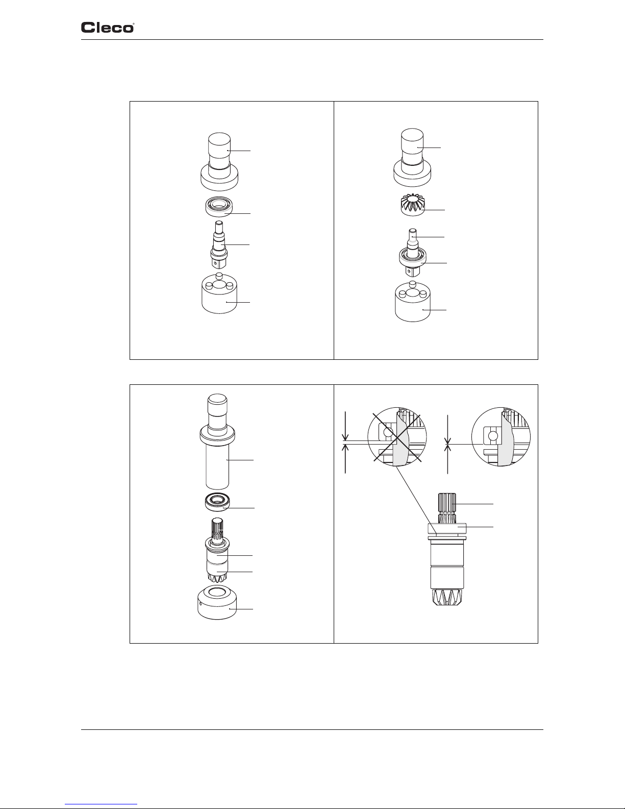
9.1 Handle
2
4
3
1
5
6
7
(8)
11
9
10
12
22
36
OFF
1,2 - 1,6 Nm
0.9 - 1.2 lbf.ft
Loctite #242
931030 SW 2,5
OFF
2,7 - 2,9 Nm
1.9 - 2.0 lbf.ft
Loctite #242
913947 SW 3
OFF
0,9 - 1,0 Nm
0.6 - 0.7 lbf.ft
Loctite #242
931030 SW 2,5
!
NOTE: DO NOT OPEN!
Shown for reference only

91f_Ersatzteile en.fm, 24.09.2007 P1891E/EN 09/07 49
Spare parts
9
For information only. These parts are not user serviceable.
Refer to Section 11 Service.
2) Quantity
Index 2) Description
1 1 accupack
2 2 cap screw
3 2 cap screw
4 1 holding angle
5 1 adapter accu asm.
6 1 adapter asm.
7 1 measuring system asm.
8 1 flat flexible cable asm.
9 2 cap screw
10 2 retaining washer
11 1 handle asm.
50 P1891E/EN 09/07 91f_Ersatzteile en.fm, 24.09.2007
Spare parts
9
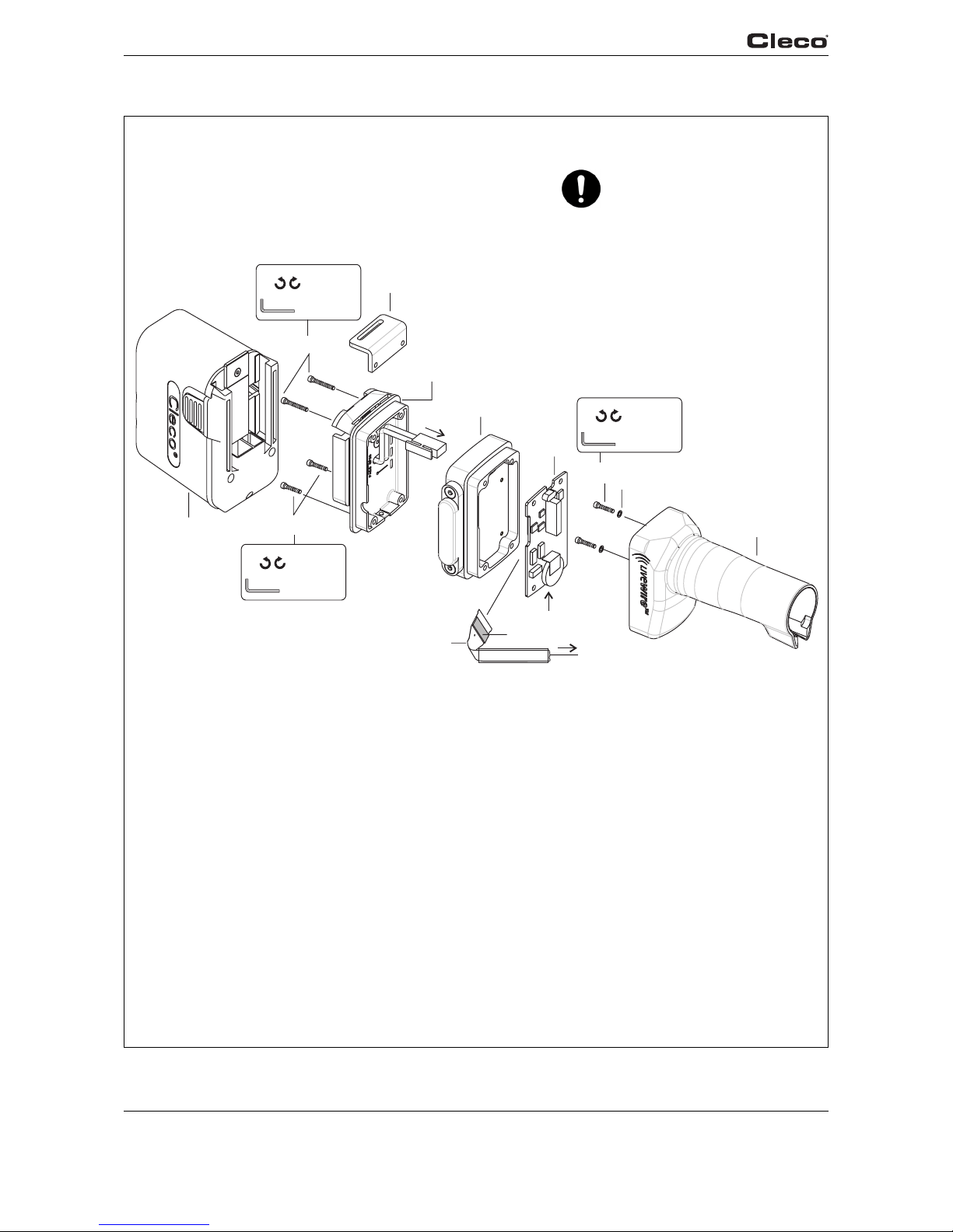
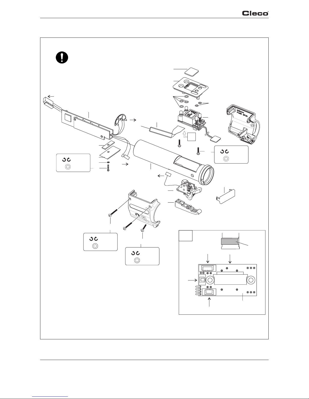
9.2 Servo bar, LCD bar & trigger components
X
13
16
17
14
12
15
26
27
18
19
22
25
23
28
24
20
21
5
31
31
22
8
7 (4 Pin)
39
(2 Pin)
26 (6 Pin)
X
22
(8)
OFF
1,1 - 1,3 Nm
0.8 - 1.0 lbf.ft
TX 10
OFF
1,1 - 1,3 Nm
0.8 - 1.0 lbf.ft
TX 10
OFF
1 - 1,25 Nm
0.7 - 0.9 lbf.ft
TX 08
OFF
1,1 - 1,3 Nm
0.8 - 1.0 lbf.ft
TX 10
!
NOTE: DO NOT OPEN!
Shown for reference only

91f_Ersatzteile en.fm, 24.09.2007 P1891E/EN 09/07 51
Spare parts
9
For information only. These parts are not user serviceable.
Refer to Section 11 Service.
2) Quantity
Index 2) Description
12 1 servo bar actuator
13 1 plate centre
14 1 plate holding
15 1 retaining washer
16 1 raised countersunk head
screw
17 1 handle sleeve asm.
18 1 LCD window
19 1 cover
20 2 o-ring
21 4 o-ring
22 1 card LCD asm.
23 2 raised countersunk head
screw
24 2 raised countersunk head
screw
25 1 raised countersunk head
screw
26 1 switch asm.
27 1 trigger

52 P1891E/EN 09/07 91f_Ersatzteile en.fm, 24.09.2007
Spare parts
9
9.3 Motor
32
33
34
35
38
36
40
(7)
39
37
29
30
31
12
22
22
22
OFF
1,8 - 2,4 Nm
1.3 - 1.8 lbf.ft
Loctite #242
931030 SW2,5
OFF
47 54 Nm
34,5 40 lbf.ft
Loctite #242
933339
Ø 4
NOTE: DO NOT OPEN!
Shown for reference only

91f_Ersatzteile en.fm, 24.09.2007 P1891E/EN 09/07 53
Spare parts
9
For information only. These parts are not user serviceable.
Refer to Section 11 Service.
2) Quantity
Index 2) Description
29 1 union nut
30 1 tension sleeve
31 1 electric motor
32 1 pinion gear
33 1 adapter shaft
34 1 spring washer
35 1 motor housing asm.
36 1 cover segment
37 4 countersunk screw
38 1 light housing
39 1 LED asm.
40 1 circlip

54 P1891E/EN 09/07 91f_Ersatzteile en.fm, 24.09.2007
Spare parts
9
9.4 Gear + angle attachment
7.3 Lubricants, page 37
13
15
1
2
3
4
5
6
8
9
10
11
12
14
7
17
16
ø4
OFF
54 - 68 Nm
40 - 50 lbf.ft
Loctite #242
31,8 (1.245)
ø4
OFF
40 - 42 Nm
29,5 - 31 lbf.ft
Loctite #242
933336
9×12
OFF
40 - 42 Nm
29,5 - 31 lbf.ft
933336
9×12
*
Typ 14 4 5 6 8 9 10 11 12 15 16 17
47BA…15AM3 935263 542722 541899 541894 542233 541888 541897 923095 542099 935313 – –
47BA…21AM3 935262 542722 – 541893 542231 541888 541894 923095 542079 935313 – –
47BA…28AM3 935261 542722 – 541893 542232 541888 541897 923095 542099 935313 – –
47BA…35AM3 935261 542722 – 541893 542232 541888 541897 923095 542099 – 935356 525943
47BA…50AM3 935264 935748 – 541893 935754 924066 935749 930228 935751 – 935753 525943

91f_Ersatzteile en.fm, 24.09.2007 P1891E/EN 09/07 55
Spare parts
9
1) Order no.
2) Quantity
3) Dimensions
• Recommended spare part for every 5 tools
* See table, page 54
Index 1) 2)
•
Description 3)
1 800116 1 circlip 25,98X0,94 IR
2 541887 1 washer
3 542724 2 o-ring 28,24X 0,78
4 * 1 gear ring
5 * 1 1 pinion gear
6 * 3 6 idler gear
7 923095 3 6 needle bearing 3,X5,X 7,
8 * 1 planet carrier
9 * 3 6 needle roller
10 * 3 6 idler gear
11 * 3 6 needle bearing
12 * 1 planet carrier
13 502983 1 thrust washer 15,88X 28,58X 1,56
14 * 1 gear
15 * 1 angle attachment
16 * 1 gear case asm.
17 * 1 angle attachment

56 P1891E/EN 09/07 91f_Ersatzteile en.fm, 24.09.2007
Spare parts
9
9.5 Angle attachment 935313
24
26
28
29
27
25
32
33
34
37
38
39
31
30
36
912724
912724
Assembly / disassembly see
7.5 Removing angle attachment 935313, page 38
7.6 Installing angle attachment 935313, page 39
9.8 Fixture order list for angle attachment 935313, page 62

91f_Ersatzteile en.fm, 24.09.2007 P1891E/EN 09/07 57
Spare parts
9
1) Order no.
2) Quantity
3) Dimensions
• Recommended spare part for every 5 tools
Index 1) 2)
•
Description 3)
24 504970 1 o-ring 7,65X1,78
25 934023 1 threaded ring
26 934035 1 2 ball bearing 10,X 22,X 6,
27 934021 1 sleeve
28 934027 1 2 needle bearing 12,7 X 19,05X12,7
29 933792 1 bevel gear set
30 915064 1 ball bearing 12,X 24,X 6,
31 933892 1 1 drive spindle asm.
32 26989 1 plug
33 9D6481 1 compression spring 0,3 X 3,2 X9,2
34 914517 1 pin
36 935312 1 angle attachment
37 918163 1 seal shaft 15,X 21,X 3,
38 905084 1 o-ring 26,X1,5
39 929177 1 union nut asm.
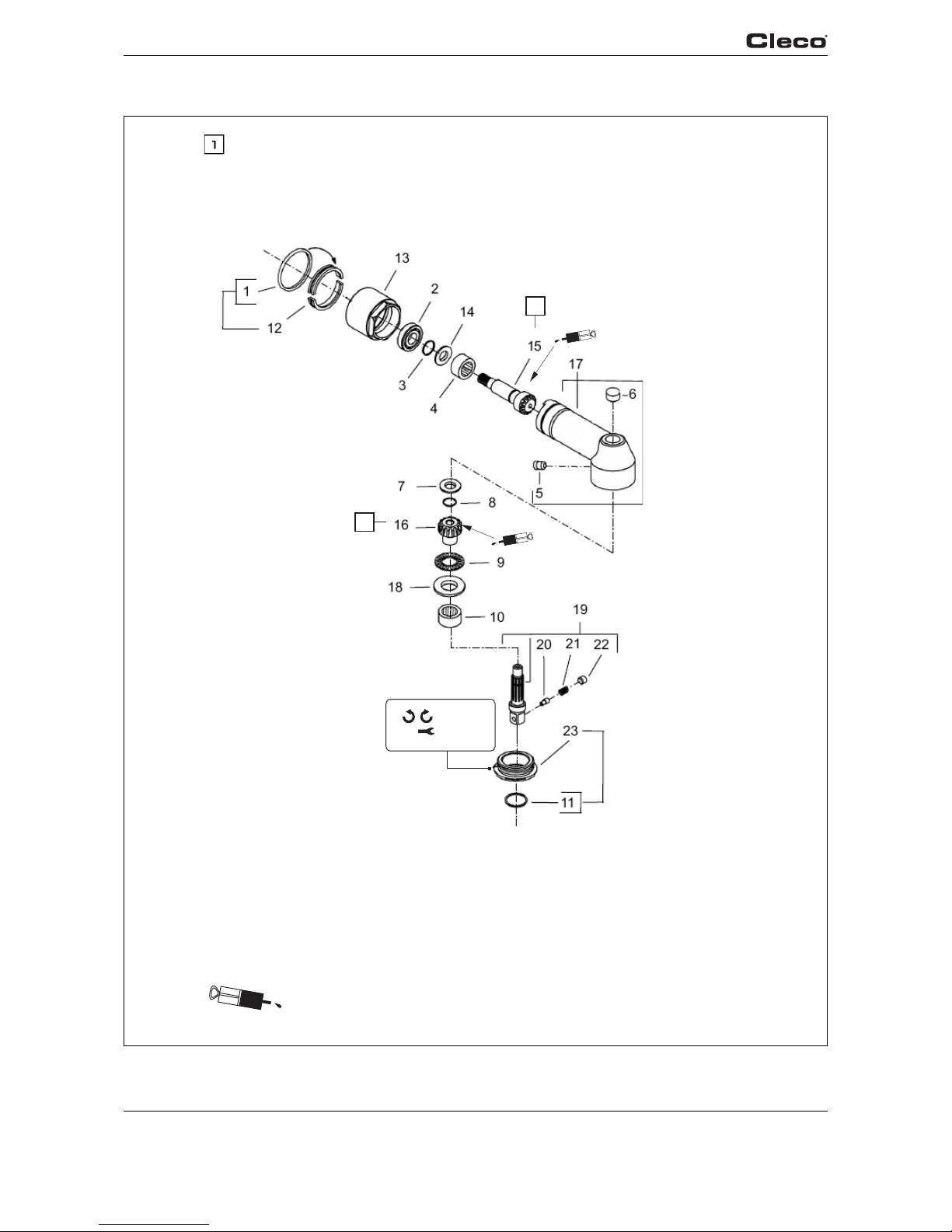
58 P1891E/EN 09/07 91f_Ersatzteile en.fm, 24.09.2007
Spare parts
9
9.6 Angle attachment 525943
Always replace <15> and <16> as a set
1
1
OFF
54 – 68 Nm
40 – 50 lbf.ft
31,75 (1.25”)
Loctite #242
541444
541444
7.3 Lubricants, page 37

91f_Ersatzteile en.fm, 24.09.2007 P1891E/EN 09/07 59
Spare parts
9
1) Order no.
2) Quantity
3) Dimensions
• Recommended spare part for every 5 tools
Index 1) 2)
•
Kits Description 3)
1 526483 1 1 Rubber Band
2 19469 1 1 Ball Bearing
10, X 26, X 8,
3 250497 1 1 Retaining Ring
4 526916 1 1 Needle Bearing
15,88X 22,21X15,88
5 27210 1 Grease Fitting
6 800170 1 1 Needle Bearing
7,94X 12,70X11,10
7 510732 1 Thrust Washer
8 513000 1 1 Retaining Ring
9,19X0,89 AR
9 259141 1 1 Thrust Bearing
15,93X 28,32X 2,
10 500487 1 1 Needle Bearing
15,88X 20,64X 7,93
11 30573 1 1 Seal
12 525878 1 Split Ring
13 525879 1 Lock Nut
14 541694 1 1 Locking Ring
15 525819 1 1 K19 Bevel Pinion
16 510695 1 1 K19 Bevel Gear
17 525890 1 Angle Housing
18 510722 1 1 Thrust Washer
16, X 28,6 X 1,56
19 510689 1 Spindle (3/8) "
20 24499 1 K20 Button
21 9D6481 1 K20 Spring
22 26989 1 K20 Plug
23 510692 1 Retaining Nut
Repair Kits:
K19 301580 1 Bevel Gear Kit
K20 301219 1 Output Spindle Kit

60 P1891E/EN 09/07 91f_Ersatzteile en.fm, 24.09.2007
Spare parts
9
9.7 Tool holder 935290 with IrDA interface port / 935395 without
*
Typ IrDA 52 53 54
935290 × 935303 935170 917735
935395 – – – –

91f_Ersatzteile en.fm, 24.09.2007 P1891E/EN 09/07 61
Spare parts
9
1) Order no.
2) Quantity
3) Dimensions
• Recommended spare part for every 5 tools
* See table, page 60
Index 1) 2)
•
Description 3)
45 S900983 2 cap 40,X40,
46 S900418 2 slot nut M 8
47 935292 1 brace
48 935293 1 support
49 935294 1 support
50 935291 2 plug
51 902490 2 cap screw M 8X 65
52 * 1 locking cover
53 * 1 IrDA-Serial Adapter
54 * 1 dowel pin 6,X 50,

62 P1891E/EN 09/07 91f_Ersatzteile en.fm, 24.09.2007
Spare parts
9
9.8 Fixture order list for angle attachment 935313
Index Order no. Description
A 933450 Assembly drive spindel
A1 933451 Punch
A2 933453 Base
A3 933452 Punch
B 933454 Assembly bevel gear
B1 933455 Punch
B2 933456 Base
C 933449 Assembyl bevel gear
in angle attachment
B1 933455 Punch
C2 933463 Semi-monocoque pair
C3 933458 Base
D 933448 Disassembly bevel gear
D1 900009 Cap screw M6×25
D2 933459 Thrust pas
D3 933460 Sleeve
D4 933461 Extraction pin
D5 933462 Semi-monocoque pair
E 933428 Socket wrench insert WAF 24
F 933427 Socket wrench insert D16
– 933336 Hook wrench
Tighten angle attachment – gear

91g_TechnDaten en.fm, 24 .09.2007 P1891E/EN 09/07 63
Technical data
10
10 Technical data
10.1 Dimensions
4kt 3/8"
ø30
12,7
26,8
ø25,4
ø46,5
57
122
ø39
L2
94,2
104,3
L3
L4
L1
66,4
56,4
39
Without scanner
Typ e L1 L2 L3 L4
47BAB15AM3
553.5 –
––
47BAB21AM3
47BAB28AM3
47BAWB15AM3
567.5 14.2
47BAWB21AM3
47BAWB28AM3
47BAXB15AM3
47BAXB21AM3
47BAXB28AM3
47BARB15AM3
47BARB21AM3
47BARB28AM3
47BAFB15AM3
47BAFB21AM3
47BAFB28AM3
With scanner
Typ e L1 L2 L3 L4
47BAWSB15AM3
567.5 14.2 43 18
47BAWSB21AM3
47BAWSB28AM3
47BAXSB15AM3
47BAXSB21AM3
47BAXSB28AM3
47BARSB15AM3
47BARSB21AM3
47BARSB28AM3
47BAFSB15AM3
47BAFSB21AM3
47BAFSB28AM3
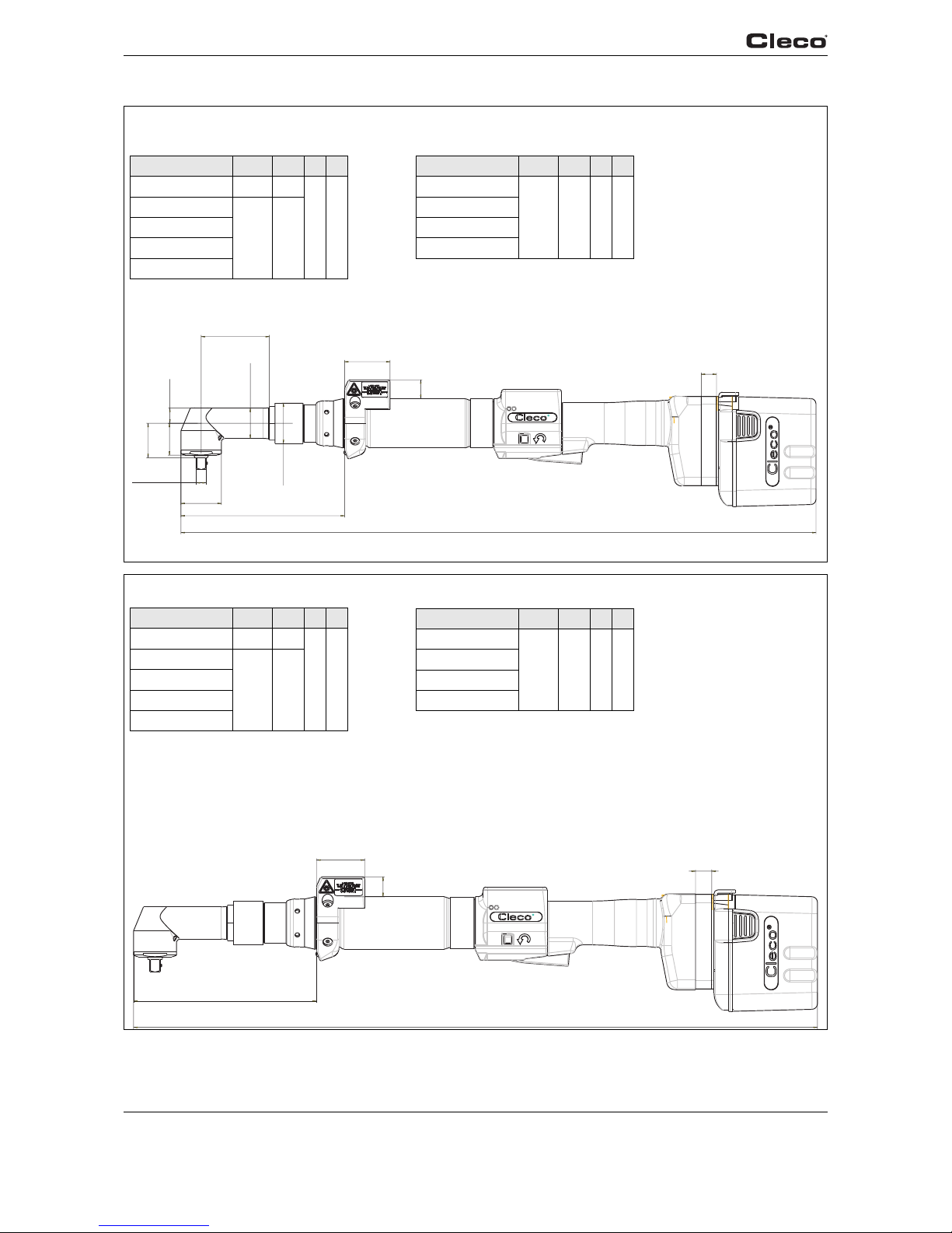
64 P1891E/EN 09/07 91g_TechnDaten en.fm, 24.09.2007
Technical data
10
4kt 3/8"
ø38,4
30,1
32,5
ø28,6
154,473
L1
64,43
L3
L4
L2
ø38,1
14,3
Without scanner
Typ e L1 L2 L3 L4
47BAB35AM3 585.5
––
47BAWB35AM3
600 14,2
47BAXB35AM3
47BARB35AM3
47BAFB35AM3
With scanner
Typ e L1 L2 L3 L4
47BAWSB35AM3
600 14.2 43 18
47BAXSB35AM3
47BARSB35AM3
47BAFSB35AM3
162,6
L1
L4
L3
L2
Without scanner
Typ e L1 L2 L3 L4
47BAB50AM3 594 –
––
47BAWB50AM3
608 14.2
47BAXB50AM
47BARB50AM3
47BAFB50AM3
With scanner
Typ e L1 L2 L3 L4
47BAWSB50AM3
608 14.2 43 18
47BAXSB50AM3
47BARSB50AM3
47BAFSB50AM3

91g_TechnDaten en.fm, 24 .09.2007 P1891E/EN 09/07 65
Technical data
10
10.2 Dimensions of tool holder (Optional)
Fig. 10-1: Dimensions of tool holder (mm)
40
40
125
20
125
110
120
90
303
319
175
80
89
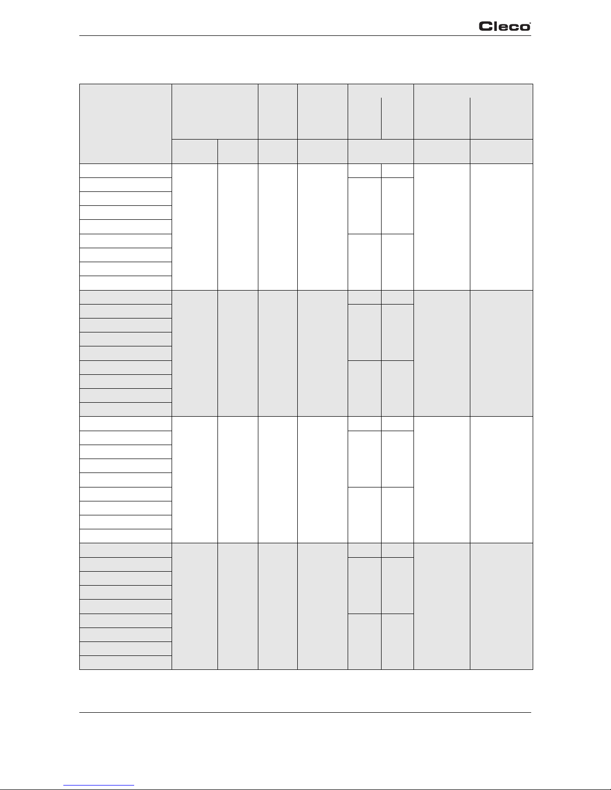
66 P1891E/EN 09/07 91g_TechnDaten en.fm, 24.09.2007
Technical data
10
10.3 Performance Data
Typ e Recommended
torque range
Idling
speed
Screw
size
8.8
Weight Calibration data
without
Rechar
geable
battery
with
Rechar
geable
battery
Tor que
(nominal)
Angle pulses
(Resolver)
Nm
max.
Nm
min.
rpm mm kg Nm ¹ degrees
47BAB15AM3
15 5.5 538 M6
1.95 2.42
16.35 1.4464
47BAWB15AM3
2.05 2.52
47BAXB15AM3
47BARB15AM3
47BAFB15AM3
47BAWSB15AM3
2.10 2.57
47BAXSB15AM3
47BARSB15AM3
47BAFSB15AM3
47BAB21AM3
21 8 411 M6
1.95 2.42
22.91 1.8941
47BAWB21AM3
2.05 2.52
47BAXB21AM3
47BARB21AM3
47BAFB21AM3
47BAWSB21AM3
2.10 2.57
47BAXSB21AM3
47BARSB21AM3
47BAFSB21AM3
47BAB28AM3
28 10 291 M8
1.95 2.42
41.35 2.6727
47BAWB28AM3
2.05 2.52
47BAXB28AM3
47BARB28AM3
47BAFB28AM3
47BAWSB28AM3
2.10 2.57
47BAXSB28AM3
47BARSB28AM3
47BAFSB28AM3
47BAB35AM3
35 12 244 M8
2.23 2.70
49.23 3.1817
47BAWB35AM3
2.33 2.80
47BAXB35AM3
47BARB35AM3
47BAFB35AM3
47BAWSB35AM3
2.38 2.85
47BAXSB35AM3
47BARSB35AM3
47BAFSB35AM3
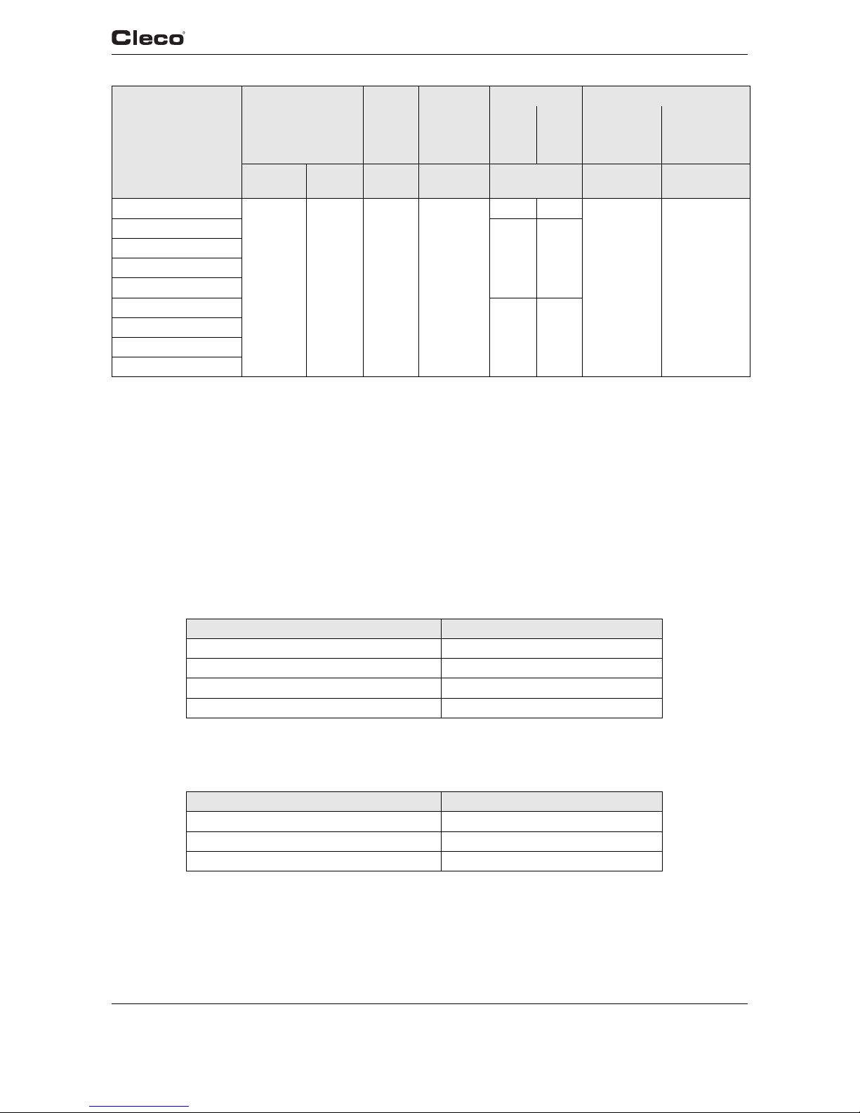
91g_TechnDaten en.fm, 24 .09.2007 P1891E/EN 09/07 67
Technical data
10
10.4 Electrical data
Tool
Protection class III as per DIN EN 61140 (VDE 0140-1)
Degree of protection IP40 as per DIN EN 60529 (IEC 60 529)
Tool holder
Protection class III as per DIN EN 61140 (VDE 0140-1)
Degree of protection IP40 as per DIN EN 60529 (IEC 60 529)
10.4.1 Battery power supply
10.4.2 Output stage servo electronics
47BAB50AM3
50 18 182 M10
2.28 2.75
57.17 3.1817
47BAWB50AM3
2.38 2.85
47BAXB50AM3
47BARB50AM3
47BAFB50AM3
47BAWSB50AM3
2.43 2.90
47BAXSB50AM3
47BARSB50AM3
47BAFSB50AM3
Features Data
Battery type Lithium ion (Li-ion)
Nominal capacity 1,600 mAh
Rated voltage 26 V
Battery self-discharge approx. 0.3 mA
Features Data
Nominal motor phase current 8 A peak value, sine
Rated output 150 VA
Maximum power 500 VA
Typ e Recommended
torque range
Idling
speed
Screw
size
8.8
Weight Calibration data
without
Rechar
geable
battery
with
Rechar
geable
battery
Tor que
(nominal)
Angle pulses
(Resolver)
Nm
max.
Nm
min.
rpm mm kg Nm ¹ degrees

68 P1891E/EN 09/07 91g_TechnDaten en.fm, 24.09.2007
Technical data
10
10.4.3 Control electronics
10.4.4 IrDA interface port
10.4.5 Scanner
Features Data
Rated voltage 26 V
Nominal current in
Active operating mode 105 mA
Nominal current in
Standby operating mode 95 mA
Nominal current in
Power-saving operating
mode
55 mA
Nominal current in
Sleep operating mode < 1 mA
Features Data
Supply voltage 5.0 V (4.8 to 5.5 V)
Power consumption 0.30 VA
Maximum current 11 mA
Transmission rate 57.6 Kbps
Parity Bit None
Data Bit 8 bit
Stop Bit 1 bit
Error check CRC
Features Data
Scan rate 104 scans/sec. ±12 (bidirectional)
Scan angle 47° ±3 standard / 35° ±3 reduced
Crash resistance 2000 G
Ambient light 107,640 lux
Decode zone (typical) 4 mil 2.54 – 13.97 cm
5 mil 3.18 – 20.32 cm
7.5 mil 3.81 – 33.66 cm
10 mil 3.81 – 44.45 cm
100% 3.81 – 59.69 cm
15 mil 3.81 – 74.93 cm
20 mil 4.45 – 90.17 cm
40 mil
1)
– 101.60 cm
55 mil
1)
– 139.70 cm
1) Depending on the width of the barcode
Laser safety IEC 60825
EMI/RFI FCC Part 15 Class B
EN 55024/CISPR 22
AS 3548
VCCI

91g_TechnDaten en.fm, 24 .09.2007 P1891E/EN 09/07 69
Technical data
10
10.4.6 WLAN data transmission
The WLAN data transmission functions may vary depending on the tool configuration.
Series 47BAW…
Series 47BAX…
Features Data
Standard IEEE 802.11b
Safety WEP64, WEP128, WPA
Range Typically up to 50 m (164’ 0.5”)
Channels 1 – 11 (2.412 – 2.462 GHz)
Transmission rate 15 dBm typical
Sensitivity -93 dBm (typ. @ 1 Mbps)
-84 dBm (typ. @ 11 Mbps)
Modulation DSSS/CCK
Standards EN 300328
EN 60950/2000
EN 301489-1/-17
FCC Part 15
Features Data
Standard IEEE 802.11b
Safety WEP
• 64/128 bit encryption
WPA/WPA2/802.11
• 128 bit TKIP/CCMP encryption
• 8021.x EAP authentication
(LEAP, PEAP, TTLS, GTC, MD5,
OTP, PAP, CHAP, MSCHAP,
MSCHAPv2, TTLS MSCHAPv2)·
• Pre-shared key mode (PSK)
Range Typically up to 50 m (164’ 0.5”)
Channels 1 – 11 (2.412 – 2.462 GHz)
Transmission rate: 16 dBm typical
Sensitivity -92 dBm (typ. @ 1 Mbps)
-82 dBm (typ. @ 11 Mbps)
Modulation CCK/DQPSK/DBPSK
Standards EN 300328
EN 60950
EN 301489-3
FCC Part 15

70 P1891E/EN 09/07 91g_TechnDaten en.fm, 24.09.2007
Technical data
10
10.4.7 868 MHz data transmission
10.4.8 915 MHz data transmission
10.4.9 Torque transducer
Torque is measured by a reaction transducer with expandable measurement strips. The reaction
transducer is positioned between the motor and the gears in the handle housing.
Features Data
Frequency 868 – 870 MHz
Channels Band 1i (869.4 MHz – 869.65 MHz): 1
Band 1k (869.7 MHz – 870.0 MHz): 2
Modulation GFSK
Output power Band 1i (869.4 MHz – 869.65 MHz):
1, 5, 10, 25 mW
Band 1k (869.7 MHz – 870.0 MHz):
1, 5 mW
Sensitivity (BER < 10-3) -100 dBm
Wireless transmission rate 38.4 kbps
Range Band 1i (869.4 MHz – 869.65 MHz):
up to 30 m (98.4”)
Band 1k (869.7 MHz – 870.0 MHz):
up to 10 m (32.8”)
Features Data
Frequency 902 – 928 MHz
Channels 8
Modulation GFSK
Output power 1 – 25 mW
3 – 14 dBm
Sensitivity (BER < 10-3) -98 dBm
Wireless transmission rate 38.4 kbps
Range up to 30 m (98.4”)
Features Data
Nominal calibration see 10.3 Performance Data, page 66
Sensitivity 2mV/V
Bridge ohms 1000 Ohm
Precision class 0.5% of final value
Linearity error +0.25 % of final value
Measurement range -125% to +125% of final value

91g_TechnDaten en.fm, 24 .09.2007 P1891E/EN 09/07 71
Service
11
11 Service
NOTE
If repair is required send the complete 47BA to Cooper Power Tools. A repair is only permitted by
Cooper Power Tools authorized personnel. If the tool is opened, the warranty is voided.
11.1 Recalibration
The type-specific calibration data is saved on the integrated screw electronic system in the
delivery state of the CLECO tool. If service is required to change the torque transducer, the
screw electronic system or if a recalibration is required, please send the CLECO tool to
Cooper Power Tools. This will ensure that after the service work, any required calibration data
update is carried out properly.
12 Disposal
CAUTION!
Injuries and environmental damage from improper disposal.
Components and auxiliary materials of the tool pose risks to the health and the environment.
➔ Catch auxiliary materials (oils, greases) when drained and dispose of them properly.
➔ Separate the components of the packing and dispose of them by segregating them
clearly.
➔ Follow the locally applicable regulations.
Observe generally valid disposal guidelines such as, in Germany, the Electrical and Electronic
Equipment Act (ElektroG) and Battery Ordinance (BattV):
➔ Return the tool and defective/used batteries to your company collection facility or to
Cooper Power Tools.
➔ Do not throw the batteries in household refuse, fire or water.

Sales & Service Centers
DALLAS, TX
Cooper Power Tools
Sales & Service
1470 Post & Paddock
Grand Prairie, TX 75050
Phone: (972) 641-9563
Fax: (972) 641-9674
DETROIT, MI
Cooper Power Tools
Sales & Service
4121 North Atlantic Blvd.
Auburn Hills, MI 48326
Phone: (248) 391-3700
Fax: (248) 391-6295
HOUSTON, TX
Cooper Power Tools
Sales & Service
6550 West Sam Houston
Parkway North, Suite 200
Houston, TX 77041
Phone: (713) 849-2364
Fax: (713) 849-2047
York, PA
Cooper Power Tools
Sales & Service
3990 East Market Street,
York, PA. 17402
Phone: (717) 755-2933
ext.2600
Fax: (717) 757-5063
LEXINGTON, SC
Cooper Power Tools
Sales & Service
670 Industrial Drive
Lexington, SC 29072
Phone: (803) 951-7510
Outside the U.S.: 010-1-803-951-7510
Custom. Service Phone: 1-800-845-5629
Fax: (803) 996-2400
Seattle, WA
Cooper Power Tools
2865 152nd Ave NE
Redmond, WA 98052
Attn: Brian Roberts
Phone: (425) 497-0479
Fax: (425) 497-0496
BRAZIL
Cooper Power Tools
Sales & Service
Av. Liberdade, 4055
Zona Industrial - Iporanga
18087-170 Sorocaba, SP Brazil
Phone: (011) 55 15 238 3929
Fax: (011) 55 15 228 3260
CANADA
Cooper Power Tools
Sales & Service
5925 McLaughlin Road
Mississauga, Ontario L5R 1B8
Canada
Phone: (905) 501-4785
Fax: (905) 501-4786
CHINA
Cooper Electric (Shanghai)
Co.,Ltd
955 Sheng Li Road
Heqing Pudong
Shanghai, China 201201
China
Phone: +86-21-28994176
28994177
Fax: +86-21-51118446
FRANCE
Cooper Power Tools SAS
Sales & Service
Zone Industrielle
B.P. 28
Avenue Maurice Chevalier
77831 Ozoir-la-Ferrière cédex
France
Phone: (33) 01 6443 2200
Fax: (33) 01 6440 1717
GERMANY
Cooper Power Tools GmbH & Co. OHG
Sales & Service
Postfach 30
D-73461 Westhausen
Phone: +49 (0) 7363 81-0
Fax: +49 (0) 7363 81-222
MEXICO
Cooper Power Tools
de México S.A. de C.V.
Libramiento La Joya No. 1
Bodega No.2
Esq. Politécnico,
Barrio San José
Cuautitlán,
Edo de México C.P. 54870
Phone: (011) 525 5899 9510
Fax: (011) 525 5870 5012
HUNGARIA
Cooper Tools Hungária Kft.
Berkenyefa sor 7
H-9027 Györ
Hungary
Phone: +36-96505-300
Fax: +36-96505-301
 Loading...