


Service Manual
PL12-1012EN
09/20/2012
19P & 19T Series
Pistol Grip Screwdrivers
19P Series
19T Series
For additional product information visit our website at http://www.apextoolgroup.com

PL12-1012EN
09/20/2012
Cleco
®
General Information
For this Instruction Manual
This Instruction Manual is the Original Instruction Manual intended for all persons who will operate and maintain
these tools.
This Instruction Manual
provides important notes for the safe and efcient use of these tools.•
describes the function and operation of the 19P and 19T series tools.•
serves as a reference guide for technical data, service intervals and spare parts ordering.•
provides information on optional equipment.•
Identication text:
19P / 19T represents all models of the pistol grip pneumatic screwdrivers as described in this manual
Ú indicates a required action
• indicates a list
<..> indicates a reference number from the exploded parts drawings
Arial indicates an important feature or instruction written in Arial Bold
Identication graphic:
¢ indicates a directional movement
ò indicates a function or force
Copyright protection:
Apex Tool Group, LLC reserves the right to modify, supplement or improve this document or the product without
prior notice. This document may not be reproduced in any way, shape or form, in full or parts thereof, or copied
to another natural or machine readable language or to a data carrier, whether electronic, mechanical, optical or
otherwise without the express permission of Apex Tool Group, LLC.
Page 2

Cleco
19 X X A XX Q
Tool Series
19
Handle
P = Pistol Grip P-Handle
T = Pistol Grip T-Handle
Tool Type
C = Combination (Trigger/Push-To-Start)
T = Trigger
Clutch
A = Clecomatic Clutch
Maximum Torque
02 = 2.1 Nm 06 = 5.1 Nm
03 = 2.9 Nm 07 = 6.8 Nm
04 = 4.5 Nm 09 = 8.9 Nm
05 = 5.1 Nm 15 = 14.7 Nm
Output Drive
Q = Quick Change Chuck
®
Nomenclature
PL12-1012EN
09/20/2012
Page 3

PL12-1012EN
09/20/2012
1 Safety 6
1.1 Warning and notes ................................................................................................. 6
1.2 Basic requirements for safe working practices ...................................................... 7
1.3 Operator training .................................................................................................... 7
1.4 Personal protective equipment .............................................................................. 7
1.5 Designated use ...................................................................................................... 8
1.6 Codes and standards ............................................................................................8
1.7 Noise and vibration ................................................................................................8
2 Scope of supply, transport and storage 9
2.1 Items supplied .......................................................................................................9
2.2 Transport ............................................................................................................... 9
2.3 Storage ..................................................................................................................9
3 Product description 10
3.1 General description .............................................................................................10
3.2 Operation and functional elements ......................................................................10
Cleco
Contents
®
4 Accessories 11
5 Before initial operation 12
5.1 Ambient conditions .............................................................................................. 12
5.2 Air supply .............................................................................................................12
5.3 Connecting the air supply to the tool ................................................................... 12
5.4 Tool set up ...........................................................................................................13
5.4.1 Setting the torque ................................................................................................ 13
6 First operation 14
6.1 Puting into use .....................................................................................................14
7 Troubleshooting 15
8 Maintenance 16
8.1 Service schedule ................................................................................................. 16
8.1.1 Calculating a customer specic maintenance plan .............................................. 17
8.2 Lubricants ............................................................................................................ 17
9 Repair instructions 18
9.1 Motor disassembly and reassembly .................................................................... 18
9.2 Trip rod sizing ...................................................................................................... 19
Page 4

Cleco
®
Contents
10 Spare parts
10.1 19P series screwdriver ........................................................................................ 20
10.2 19T series screwdriver ........................................................................................22
10.3 Motor assembly ................................................................................................... 24
10.4 301967PT Gearing assembly .............................................................................. 26
10.5 301086 Gearing assembly ................................................................................... 26
10.6 301968PT Gearing assembly .............................................................................. 28
10.7 301969PT Gearing assembly .............................................................................. 28
10.8 302016PT Gearing assembly .............................................................................. 30
10.9 301970PT Gearing assembly .............................................................................. 32
10.10 301991PT Clecomatic clutch assembly ............................................................... 34
301979PT Clecomatic clutch assembly ............................................................... 34
10.11 302017PT Clecomatic clutch assembly ............................................................... 36
10.12 301981PT Clecomatic clutch assembly ............................................................... 38
10.13 301124 Output gear assembly ............................................................................. 40
10.14 301122 Output spindle assembly ........................................................................40
11 Technical data 42
PL12-1012EN
09/20/2012
11.1 19PCA and 19TCA Specications .......................................................................42
11.2 19PTA and 19TTA Specications.........................................................................42
12 Service 43
12.1 Replacement parts ..............................................................................................43
12.2 Tool repairs .......................................................................................................... 43
12.3 Warranty repairs .................................................................................................. 43
13 Disposal 44
Page 5

PL12-1012EN
09/20/2012
1 Safety
1.1 Warnings and notes
Warning notes are identied by a signal word and a pictogram.
The signal word indicates the severity and probability of the impending danger.•
The pictogram indicates the type of danger.•
---------------------------------------------------------------------------------------------------------------------------------------
WARNING identies a potentially hazardous situation which, if not avoided, may result in serious
injury.
---------------------------------------------------------------------------------------------------------------------------------------
---------------------------------------------------------------------------------------------------------------------------------------
CAUTION identies a potentially hazardous situation which, if not avoided, may result in minor or
moderate injury or property and environmental damage.
---------------------------------------------------------------------------------------------------------------------------------------
---------------------------------------------------------------------------------------------------------------------------------------
NOTE identies general information which may include application tips or useful information but no
hazardous situations.
---------------------------------------------------------------------------------------------------------------------------------------
---------------------------------------------------------------------------------------------------------------------------------------
Important information that must be read and understood by all personnel installing, operating or
maintaining this equipment.
---------------------------------------------------------------------------------------------------------------------------------------
Cleco
Safety
®
Page 6

Cleco
®
Safety
1.2 Basic requirements for safe working practices
All personnel involved with the installation, operation or maintenance of these tools must read and
understand all safety instructions contained in this manual. Failure to comply with these instructions
could result in serious injury or property damage.
These safety instructions are not intended to be all inclusive. Study and comply with all applicable
National, State and Local regulations.
---------------------------------------------------------------------------------------------------------------------------------------
Work Area:
ÚEnsure there is enough space in the work area.
ÚKeep the work area clean.
ÚKeep the work area well ventilated.
Personnel Safety:
ÚInspect the air supply hoses and ttings. Do not use damaged, frayed or deteriorated hoses.
ÚMake sure the air supply hose is securely attached to the tool.
ÚEnsure a secure standing position and maintain balance.
ÚMake sure the throttle is positioned relative to the head so the throttle will not become wedged
against an adjacent object in the ON position due to torque reaction.
ÚIf the tool is to be reversed, locate the throttle in a neutral position to prevent entrapment.
ÚKeep the tool clean and dry to provide the best possible grip.
ÚFirmly grasp the handle of the 19P/19T and apply the bit to the application before starting.
ÚBe prepared for high short-term reaction torques.
PL12-1012EN
09/20/2012
Safety working with and around fastening tools:
ÚUse only power tool sockets and bits available from Apex Tool Group.
ÚInspect socket or bit for visible damage and cracks. Replace damaged items immediately.
ÚDisconnect the air supply before installing or replacing the socket or bit.
ÚDo not attach the socket or bit at a slant.
ÚMake sure the socket or bit is fully assembled on the drive and locked in postion.
---------------------------------------------------------------------------------------------------------------------------------------
1.3 Operator training
All personnel must be properly trained before operating the 19P/19T tools. The 19P/19T tools are to be
repaired by fully trained personnel only.
1.4 Personal protective equipment
When working
Wear eye protection to protect against ying metal splinters.•
Wear hearing protection•
Danger of injury by being caught by moving equipment.
Wear a hairnet•
Wear close tting clothing•
Do not wear jewelry•
Page 7

PL12-1012EN
09/20/2012
1.5 Designated use
The 19P/19T are designed exclusively for fastening and releasing threaded fasteners.
The 19P/19T series screwdrivers are equipped with an adjustable Clecomatic clutch. The tool will shut
off the instant the clutch reaches its adjustable preset torque. This action provides an accurate method
of controlling torque without sacricing tool speed.
Do not modify the 19P/19T, any guard or accessory.•
Use only with accessory parts which are approved by the manufacturer.•
Do not use as a hammer, pry-bar or any other improper usage.•
1.6 Codes and standards
It is mandatory that all national, state and local codes and standards be followed.
1.7 Noise and vibration
Noise level ≤ 79 dB(A) free speed (without load) according to ISO 12100: 2011
Vibration values < 2.5 m/s2 according to ISO 12100: 2011
Cleco
Safety
®
Page 8

Cleco
Object Time Period Storage Temperature
19P without air supply No guideline -13°F to 104°F (-25°C to 40°C)
19T without air supply No guideline -13°F to 104°F (-25°C to 40°C)
®
Scope of Supply, Transport and Storage
2 Scope of supply, transport and storage
2.1 Items supplied
Check shipment for transit damage and ensure that all items have been supplied:
1 19P or 19T
1 PL12-1012EN instruction manual
1 Declaration of Conformity
1 Lubrication sheet
1 Warranty statement
2.2 Transport
Transport and store the 19P/19T in the original packaging. The packaging is recyclable.
2.3 Storage
For short term storage (less than 2 hours) and protection against damage:
ÚPlace the 19P/19T in a location on the workbench to avoid accidental depression of the trigger.
or
ÚSuspend the 19P/19T from a suitable balancer or tool positioner.
PL12-1012EN
09/20/2012
For storage longer than 2 hours:
ÚDisconnect the air supply from the 19P/19T
Page 9

PL12-1012EN
Ref. Description
1 Air Inlet
2 Adjustable Reversing Lever
3 Trigger
4 Two Interchangeable soft-touch grip sizes
5 Clecomatic Clutch
6 Motor and Gearing
7 Quick Change Chuck
09/20/2012
Cleco
Product Description
3 Product description
3.1 General description
Pistol grip or “T” handle pneumatic powered screwdriver•
Trigger actuated•
Clockwise/counterclockwise rotation•
19PCA and 19TCA models: trigger allowed push-to-start with adjustable Clecomatic clutch•
19PTA and 19TTA models: trigger start with adjustable Clecomatic clutch
Low vibration level•
3.2 Operation and functional elements
This section describes the operational and functional elements of the 19P/19T.
®
7
5 6
3
2
4
1
Page 10

4 Accessories
Cleco
®
Accessories
Suspension Bail
Part Number: 931962
Torque Signal Kit
Clecomatic clutch models only
Part Number: 301118 (19PTA)
Part Number: 301119 (19TTA)
PL12-1012EN
09/20/2012
Exhaust Overhose
Part Number: 207107 (19T)
TVP-100 Series Torque Verier
Part Number:
TVP-110-15-U (115VAC) EN
TVP-110-30-U (230 VAC) EN
Page 11

PL12-1012EN
Parameter Description
Air Hose
Minimum inside diameter: 3/16" (4,7 mm)
Maximum length: 16.4' (5 m)
Working pressure range
58 to 101.5 psi (400 to 700 kPa)
Recommended: 90 psi (620 kPa)
Compressed air
Air quality according to ISO 8573-1, quality class 2.4.3
The compressed air must be clean and dry.
Part No. Packaged Designation Vendor
540397 1 Quart (0.94 liter) Airlube 10W/NR-420LB DR Fuchs Lubricants Co.
533485 1 US Gallon (3.78 liter) Airlube 10W/NR-420LB DR Fuchs Lubricants Co.
09/20/2012
Before Initial Operation
5 Before initial operation
5.1 Ambient conditions
Ambient temperature: 41°F (5°C) to a maximum of 104°F (40°C)
Acceptable relative humidity: 25% to 90%, non-condensing
5.2 Air supply
To attain consistent results, maintain a constant working pressure using a suitable air line unit consisting
of a lter, regulator and lubricator.
ÚThe inside diameter of the air hose must be free of residue, clean if necessary.
ÚSpray a few drops of light air tool oil into the air inlet adapter.
ÚAdjust the lubricator to a minimum setting to reduce the amount of excess oil in the exhaust air.
Oil identification
Cleco
®
5.3 Connecting the air supply to the tool
---------------------------------------------------------------------------------------------------------------------------------------
The air hose can disconnect from the tool by itself and whip around uncontrollably.
ÚTurn off the compressed air before connecting to the tool.
ÚSecurely connect the air hose to the tool.
ÚTurn on the compressed air.
---------------------------------------------------------------------------------------------------------------------------------------
Page 12
5.4 Tool set up
The tool must be congured for the application.
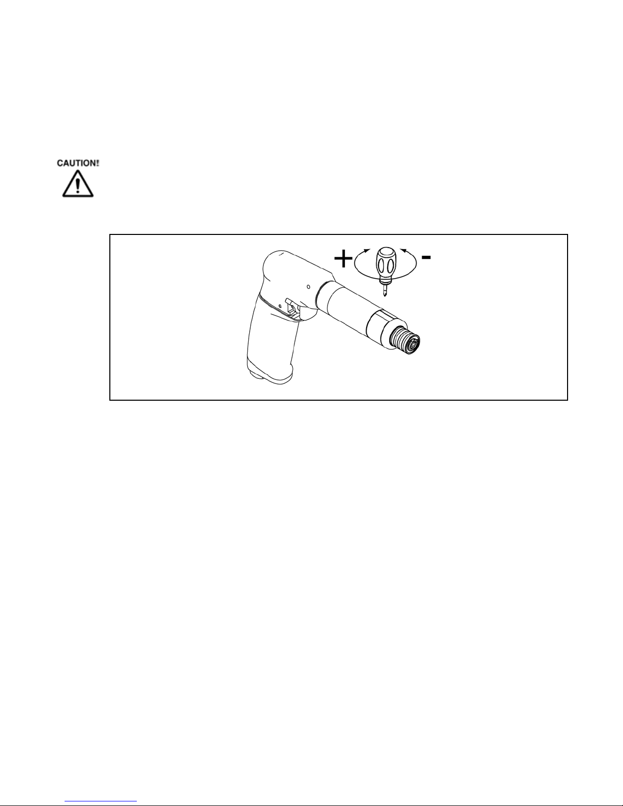
5.4.1 Setting the torque
---------------------------------------------------------------------------------------------------------------------------------------
Danger of injury from accidental start up.
Turn off the compressed air before adjusting the clutch.
---------------------------------------------------------------------------------------------------------------------------------------
ÚUsing the clutch adjustment tool provided, turn clockwise for maximum torque or counter-
clockwise for minimum torque.
Cleco
®
Before Initial Operation
PL12-1012EN
09/20/2012
204963
#1 Phillips
Clutch Adjustment Tool
Note: For best results, start from minimum torque and adjust in the maximum direction until desired
torque is achieved.
Page 13

PL12-1012EN
09/20/2012
6 First operation
6.1 Putting into use
ÚMake sure the air supply is securely attached and the compressor is turned on.
ÚMake sure the reverse lever is in the correct position.
ÚPlace the socket or bit on the application and depress the trigger to start the rundown.
ÚWhen the tool shuts off after reaching the set torque, release the trigger.
ÚRemove the tool from the application.
Cleco
®
First Operation
Page 14

7 Troubleshooting
Malfunction Possible causes Remedy
No or low air pressure
Make sure there is adequate air pressure at
the tool air inlet
Reversing lever out of position
Make sure the reversing lever is in the
clockwise or counterclockwise position
Trip rod spring out of position
Tool disassembly required
Broken gears
Tool disassembly required (parts
replacement)
Torque set to high
Reduce the torque setting
Working pressure < 58 psi (400 kPa)
Increase the working air pressure
Teeth on adjusting wrench worn or
broken
Replace adjusting wrench
Teeth on adjustment nut worn or
broken
Clutch disassembly required (parts
replacement)
Reduced air pressure
Check air supply line for any obstructions
Lack of lubrication
Check the air line lubricator to make sure it is
full of lubricant and is working properly
Motor exhaust air is obstructed
Clean or replace bronze mufflers
Swollen rotor blades from excessive
moisture
Check the air line filter, empty reservoir if
necessary
Worn rotor blades
Tool disassembly required (parts
replacement)
Worn gears or bearings
Tool disassembly required (parts
replacement)
Loose inlet adapter
Tighten inlet adapter
Worn o-ring on inlet adapter
Replace o-ring
Tool does not
start
Tool does not shut
off
Unable to adjust
torque
Tool loses power
Air leak at inlet
adapter
Cleco
®
Troubleshooting
PL12-1012EN
09/20/2012
Page 15

PL12-1012EN
Maintenance
Interval
Rundowns
Daily Daily
Visual inspection of air supply hose and connections
Inspect airline filter, regulator and lubricator for proper operation
Check the tool for excessive vibration or unusual noises
Visual inspection of all external components of the tool
W1 100,000
Inspect the air hose for damage or wear
inspect the square drive output spindle for damage or wear
Inspect the air inlet adapter for a secure fit
Check the maximum free speed
W2 500,000
Check individual parts and replace if necessary
Replace O-rings and seals
Clean bronze mufflers
W3 1,000,000
Check individual parts and replace if necessary
Throttle valve
Motor
Gearing
Clutch
Quick change chuck
Designation
09/20/2012
8 Maintenance
---------------------------------------------------------------------------------------------------------------------------------------
Danger of injury from accidental start up.
Turn off the compressed air before performing any maintenance.
---------------------------------------------------------------------------------------------------------------------------------------
8.1 Service schedule
Only qualied and trained personnel are permitted to perform maintenance on these tools.
Regular maintenance reduces operating faults, repair costs and downtime. In addition to the following
service schedule, implement a safetu related maintenance program that takes the local regulations for
repair and maintenance for all operating phases of the tool into account.
Cleco
®
Maintenance
This maintenance schedule uses values that are valid for most applications. For a specic maintenance
interval, refer to 8.1.1 Calculating a customer-specic maintenance plan.
Page 16
Cleco
Example for service interval W2:
After 500,000 rundowns (V),
a specific rundown time of 1.8 seconds (T1)
with an actual fastening time of 3 seconds (soft joint) and
3 completed shifts per day and 750 rundowns per shift.
V x T1 500000 x 1.8
T2 x S x VS 3 x 3 x 750
You will need to perform the maintenance indicated as W2 after an operating time of 133 days.)
W (1, 2, 3) =
W2 =
= 133 (days)
Factor
Value assumed in
"Service Schedule"
Description
V
V1 = 100,000
V2 - 500,000
V3 = 1,000,000
Number of rundowns after a maintenance measure is prescribed by Apex
Tool Group.
T1 1.8 seconds Specific rundown time, measured in life and endurance tests.
T2 2 seconds Actual rundown time, depending on the hardness of the joint.
S 1; 2; 3 Number of shifts per day.
VS 750 Number of rundowns per shift.
T2, S and VS are variable factors and can differ depending on the specific application.
Part No. Packaged Designation Vendor
540450 18 oz. (0.51 kg) Black Pearl EP-NLGI-0 Chevron
540395 2 oz. (0.06 kg) Magnalube-G Carleton-Stuart Corp.
513156 16 oz. (0.45 kg) Magnalube-G Carleton-Stuart Corp.
541444 2 oz. (0.06 kg) Rheolube 363AX-1 Nye Lubricants, Inc.
541445 16 oz. (0.45 kg) Rheolube 363AX-1 Nye Lubricants, Inc.
®
Maintenance
8.1.1 Calculating a customer specic maintenance plan
A service interval W(1, 2, 3) depends on the following factors:
PL12-1012EN
09/20/2012
8.2 Lubricants
For proper function and long service life, use of the correct grease is essential.
Grease lubricants recommended for this tool.
Page 17
PL12-1012EN
09/20/2012
Cleco
Repair Instructions
9 Repair instructions
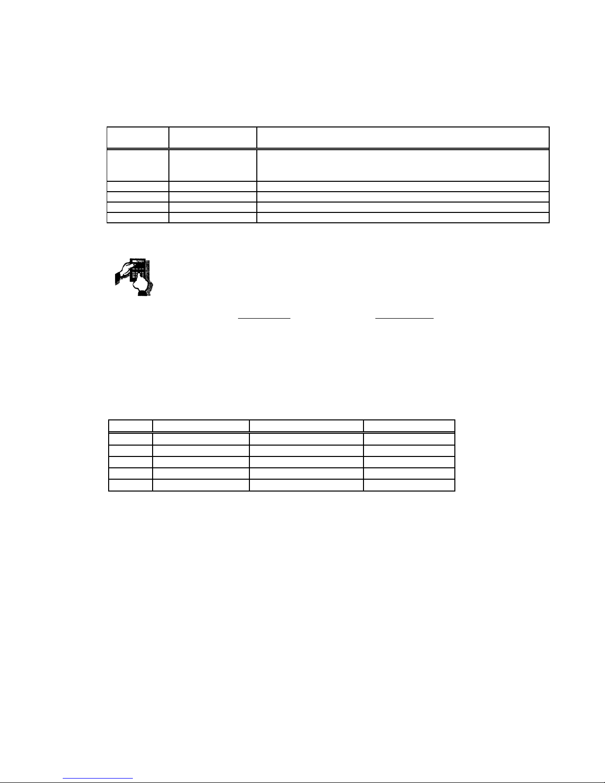
9.1 Motor disassembly and reassembly
Disassembly
®
1
Off Off
R = Replace
2
1 2 3 4
Reassembly
.0010” (.254mm)
to
.0015” (.031mm)
Page 18
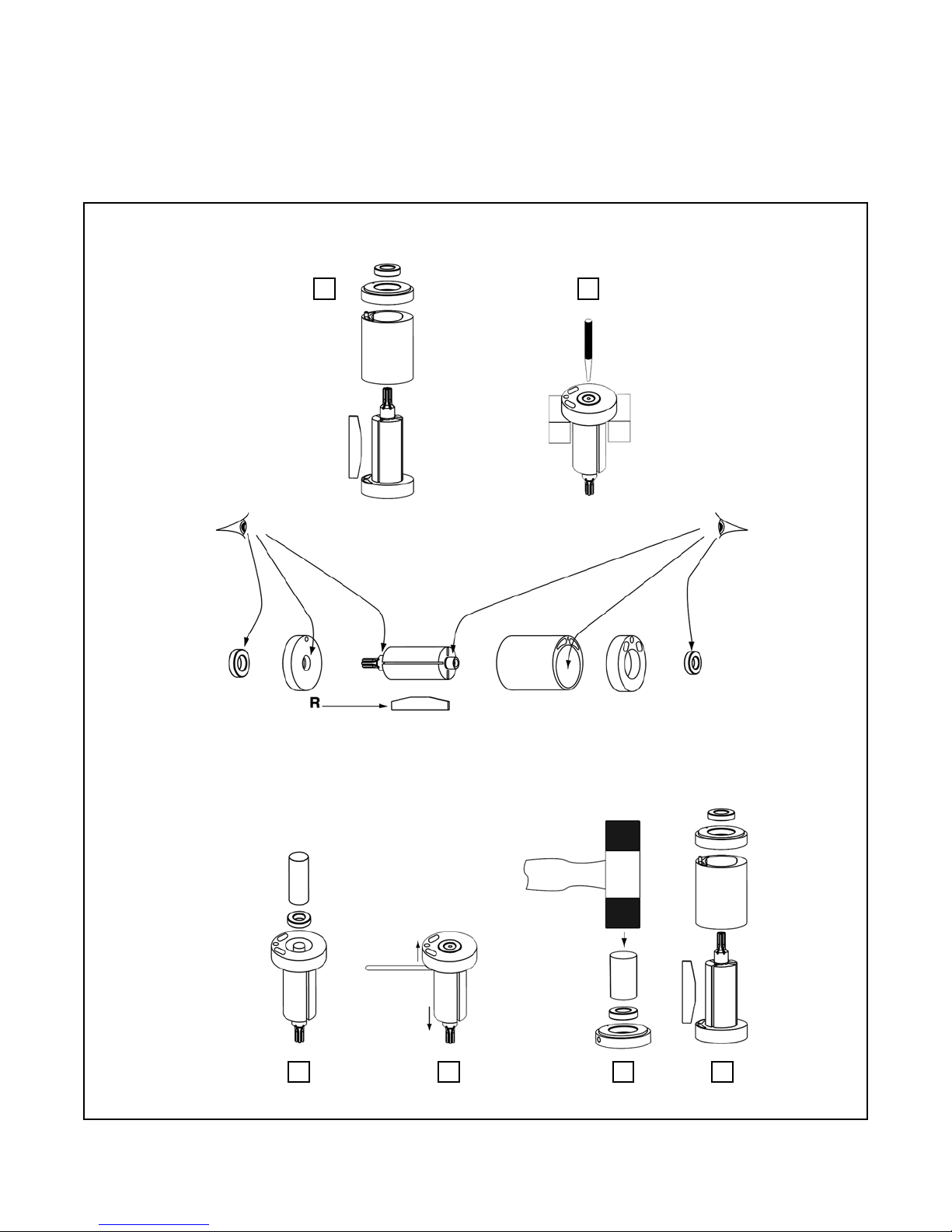
9.2 Trip rod sizing
Cleco
®
Repair Instructions
PL12-1012EN
09/20/2012
Step 1: (Kit 301409)
Assemble (2) 863009 O-Rings on the Spindle
Bushing.
Step 3: (19PCA & 19TCA models)
Remove 863009 O-Rings.
Step 2:
Shorten the Trip Rod until the tool just begins to start
with one (1) turn remaining on t he Clutch Housing.
Page 19

PL12-1012EN
09/20/2012
Cleco
®
Spare Parts
10.1 19P Series Screwdriver
31
13
15
Torque:
5-7 in. lbs.
(0.6-0.8 Nm)
16
17
Models
19PTA(--)Q
19PCA(--)Q
14
29
26
28
30
25
275
2
12
3
4
10
6
23
24
Torque:
95-105 in. lbs.
22
(10.7-11.8 Nm)
20
21
19
18
8
7
9
11
Page 20
Page 20

EN
Description
1 301963PT 1 Reversing Valve Assembly (includes Ref. 2 thru 12)
2 541528 1 3 O-Ring
3 207611PT 1 Tapered Throttle Valve
4 207612PT 1 Valve Stem
5 70193900 1 Washer
6 70191800 1 Reversing Valve Bushing
7 80047400 1 1 Spring Clip
8 207574PT 1 Reversing Valve
9 207597PT 1 Reversing Valve Lever
10 207598PT 1 2 Socket Head Set Screw
1 1 1110038 1 1 Trigger
12 93040033 1 3 O-Ring
13 207570PT 1 Pistol Grip Housing
14 847031 1 2 Dowel Pin
15 844302 1 3 O-Ring
16 812962 1 3 Screw
17 867926 1 3 O-Ring
207601PT 1 Large Pistol Grip Handle (Standard Equipment)
207595PT * 1 Small Pistol Grip Handle (Option)
19 203563 1 3 Muffler Pad
20 866400PT 1 3 Muffler
21 207587PT 1 Muffler Cap
207602PT 1 Inlet Adapter - Large Handle (Standard Equipment)
207588PT * 1 Inlet Adapter - Small Handle (Option)
23 905031 * 1 3 Screen
24 905599 * 1 3 Retaining Ring
25 203525 1 3 Shut-Off Valve Spring
26 203529 1 Shut-Off Valve
27 847675 1 3 Valve Seal
28 207594PT 1 Valve Manifold (includes Ref. 30)
29 847033 1 2 Retaining Ring
30 847548 1 2 Pin
31 931962 1 2 Suspension Bail
(#) Quantity
(X) Recommended Spare Parts (quantity shown based on 1-5 tools in operation)
* Note: Parts included in 302020PT small Pistol Grip handle kit
18
22
10.1 19P Series Screwdriver
Ref
Number
#
X
Cleco
®
Spare Parts
PL12-1012EN
09/20/2012
Page 21

PL12-1012EN
09/20/2012
Cleco
®
Spare Parts
10.2 19T Series Screwdriver
31
13
15
Torque:
5-7 in. lbs.
(0.6-0.8 Nm)
16
5
17
Models
19TTA(--)Q
19TCA(--)Q
14
29
26
28
30
25
27
2
12
3
4
10
6
23
24
Torque:
95-105 in. lbs.
22
(10.7-11.8 Nm)
20
21
19
18
8
7
9
11
Page 22

EN
Description
1 301963PT 1 Reversing Valve Assembly (includes Ref. 2 thru 12)
2 541528 1 3 O-Ring
3 207611PT 1 Tapered Throttle Valve
4 207612PT 1 Valve Stem
5 70193900 1 Washer
6 70191800 1 Reversing Valve Bushing
7 80047400 1 1 Spring Clip
8 207574PT 1 Reversing Valve
9 207597PT 1 Reversing Valve Lever
10 207598PT 1 2 Socket Head Set Screw
1 1 1110038 1 1 Trigger
12 93040033 1 3 O-Ring
13 207572PT 1 Pistol Grip Housing
14 847031 1 2 Dowel Pin
15 844302 1 3 O-Ring
16 812962 1 3 Screw
17 867926 1 3 O-Ring
207601PT 1 Large Pistol Grip Handle (Standard Equipment)
207595PT * 1 Small Pistol Grip Handle (Option)
19 203563 1 3 Muffler Pad
20 866400PT 1 3 Muffler
21 207587PT 1 Muffler Cap
207602PT 1 Inlet Adapter - Large Handle (Standard Equipment)
207588PT * 1 Inlet Adapter - Small Handle (Option)
23 905031 * 1 3 Screen
24 905599 * 1 3 Retaining Ring
25 203525 1 3 Shut-Off Valve Spring
26 203529 1 Shut-Off Valve
27 847675 1 3 Valve Seal
28 207594PT 1 Valve Manifold (includes Ref. 30)
29 847033 1 2 Retaining Ring
30 847548 1 2 Pin
31 931962 1 2 Suspension Bail
(#) Quantity
(X) Recommended Spare Parts (quantity shown based on 1-5 tools in operation)
* Note: Parts included in 302020PT small Pistol Grip handle kit
18
22
10.2 19T Series Screwdriver
Ref
Number
#
X
Cleco
®
Spare Parts
PL12-1012EN
09/20/2012
Page 23

PL12-1012EN
09/20/2012
10.3 Motor Assembly
6
Cleco
®
Spare Parts
2
1
4
8
3
5
7
6
4
Page 24

EN
Description
-- Table 10.3 1 Motor Assembly
1 203504 1 Cylinder
2 205960 1 Rear Bearing Plate
3 Table 10.3 1 Rotor
4 203615PT 4 12 Rotor Blade
5 203641 1 Front Bearing Plate
6 842768 2 4 Ball Bearing
7 844897 1 2 Front Cylinder Pin
8 847548 1 2 Rear Cylinder Pin
(#) Quantity
(X) Recommended Spare Parts (quantity shown based on 1-5 tools in operation)
10.3 Motor Assembly
Ref
Number
#
X
Cleco
Table 10.3
Ref. Description #
19(--)A02Q
19(--)A05Q
19(--)A07Q
#
19(--)A03Q
19(--)A09Q
#
19(--)A04Q
19(--)A06Q
19(--)A15Q
-- Motor Assembly 1 301972PT 1 301973PT 1 301974PT
3 Rotor 1 203545 1 203547 1 203546
®
Spare Parts
PL12-1012EN
09/20/2012
Page 25
PL12-1012EN
09/20/2012
Cleco
®
Spare Parts
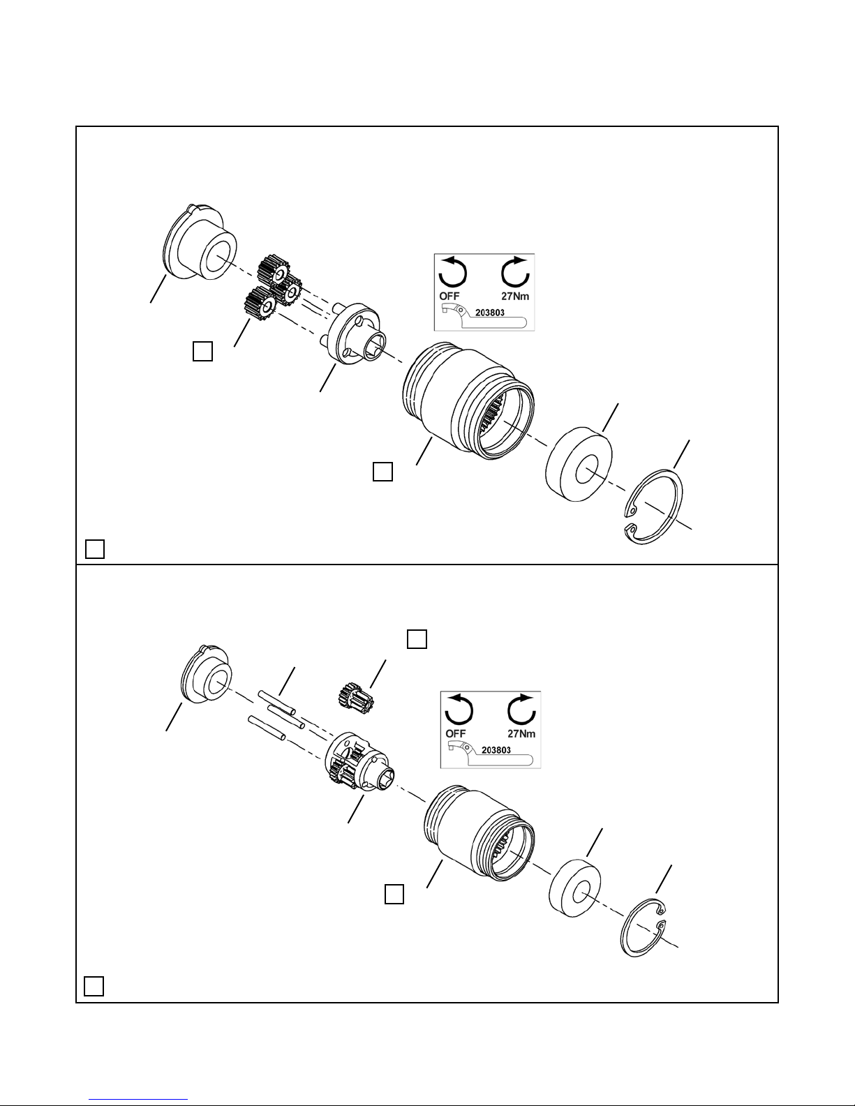
10.4 301967PT Gearing Assembly
1
L
2
3
Models
19PCA02Q
19PTA02Q
19TCA02Q
19TTA02Q
5
6
L
4
Lubricate with 540450 Grease (18 oz. can)
L
10.5 301086 Gearing Assembly
2
1
Models
19PCA03Q
19PTA03Q
L
4
19TCA03Q
19TTA03Q
6
3
7
L
5
Lubricate with 540450 Grease (18 oz. can)
L
Page 26

Cleco
EN
Description
-- 301967PT 1 Gear Case Assembly (6.875:1)
1 204136PT 1 End Plate Spacer
2 207619PT 3 6 Idler Gear (16T)
3 207620PT 1 Open Spider
4 205964 1 Gear Case
5 847595 1 2 Ball Bearing
6 619017 1 2 Retaining Ring
(#) Quantity
(X) Recommended Spare Parts (quantity shown based on 1-5 tools in operation)
(T) Teeth
10.4 301967PT Gearing Assembly
Ref
Number
#
X
EN
Description
-- 301086 1 Gear Case Assembly
1 203646 1 End Plate Spacer
2 833862 3 6 Needle Roller
3 869155 1 Spider
4 869163 3 6 Idler Gear (18/9T)
5 205966 1 Gear Case
6 847595 1 2 Ball Bearing
7 619017 1 2 Retaining Ring
(#) Quantity
(X) Recommended Spare Parts (quantity shown based on 1-5 tools in operation)
(T) Teeth
10.5 301086 Gearing Assembly
Ref
Number
#
X
®
Spare Parts
PL12-1012EN
09/20/2012
Page 27
PL12-1012EN
09/20/2012
Cleco
®
Spare Parts
10.6 301968PT Gearing Assembly
1
L
2
L
7
L
6
7
Models
19PCA04Q
19PTA04Q
19TCA04Q
19TTA04Q
19PTA15Q
19TTA15Q
L
3
L
8
5
4
Lubricate with 540450 Grease (18 oz. can)
L
10.7 301969PT Gearing Assembly
1
L
8
L
6
5
Models
19PCA05Q
19PTA05Q
19TCA05Q
19TTA05Q
19PCA07Q
19PTA07Q
19TCA07Q
19TTA07Q
L
2
L
7
4
3
Lubricate with 540450 Grease (18 oz. can)
L
Page 28

Cleco
EN
Description
-- 301968PT 1 Gear Case Assembly (17.256:1)
1 203644PT 1 End Plate Spacer
2 203919 1 2 Pinion Gear
3 205964 1 Gear Case
4 619017 1 2 Retaining Ring
5 847595 1 2 Ball Bearing
6 207615PT 1 Open Spider
7 207616PT 6 12 Idler Gear (14T)
8 207618PT 1 Open Spider
(#) Quantity
(X) Recommended Spare Parts (quantity shown based on 1-5 tools in operation)
(T) Teeth
10.6 301968PT Gearing Assembly
Ref
Number
#
X
EN
Description
-- 301969PT 1 Gear Case Assembly (28.484:1)
1 204136PT 1 End Plate Spacer
2 205963 1 Gear Case
3 619017 1 2 Retaining Ring
4 847595 1 2 Ball Bearing
5 207616PT 3 6 Idler Gear (14T)
6 207617PT 1 Open Spider
7 207618PT 1 Open Spider
8 207619PT 3 6 Idler Gear (16T)
(#) Quantity
(X) Recommended Spare Parts (quantity shown based on 1-5 tools in operation)
(T) Teeth
10.7 301969PT Gearing Assembly
Ref
Number
#
X
®
Spare Parts
PL12-1012EN
09/20/2012
Page 29

PL12-1012EN
09/20/2012
Cleco
®
Spare Parts
10.8 302016PT Gearing Assembly
3
1
L
2
L
4
Models
19PCA09Q
19PTA09Q
19TCA09Q
19TTA09Q
L
4
6
7
L
5
Lubricate with 540450 Grease (18 oz. can)
L
8
10
L
L
Page 30
11
11
L
L
9
6
7

EN
Description
-- 302016PT 1 Gear Case Assembly (41.538:1)
1 203646 1 End Plate Spacer
2 207701PT 1 Spider
3 833862 3 6 Needle Roller
4 207691PT 3 6 Idler Gear (18T and 9T)
5 205966 1 Gear Case
6 847595 2 4 Ball Bearing
7 619017 2 4 Retaining Ring
8 207702PT 1 Gear Case
9 204282 1 Gear Cage Spider
10 844111 3 6 Dowel Pin
1 1 203623PT 3 6 Idler Gear (14T)
(#) Quantity
(X) Recommended Spare Parts (quantity shown based on 1-5 tools in operation)
(T) Teeth
10.8 302016PT Gearing Assembly
Ref
Number
#
X
Cleco
®
Spare Parts
PL12-1012EN
09/20/2012
Page 31

PL12-1012EN
09/20/2012
Cleco
®
Spare Parts
10.9 301970PT Gearing Assembly
1
L
2
L
7
Models
19PCA06Q
19PTA06Q
19TCA06Q
19TTA06Q
L
6
L
7
L
6
L
7
8
Lubricate with 540450 Grease (18 oz. can)
L
3
Page 32
L
5
4

EN
Description
-- 301970PT 1 Gear Case Assembly (70.680:1)
1 203644PT 1 End Plate Spacer
2 203919 1 2 Pinion Gear
3 205963 1 Gear Case
4 619017 1 2 Retaining Ring
5 847595 1 2 Ball Bearing
6 207615PT 2 Open Spider
7 207616PT 9 18 Idler Gear (14T)
8 207618PT 1 Open Spider
(#) Quantity
(X) Recommended Spare Parts (quantity shown based on 1-5 tools in operation)
(T) Teeth
10.9 Gearing Assembly
Ref
Number
#
X
Cleco
®
Spare Parts
PL12-1012EN
09/20/2012
Page 33
PL12-1012EN
09/20/2012
Cleco
®
Spare Parts
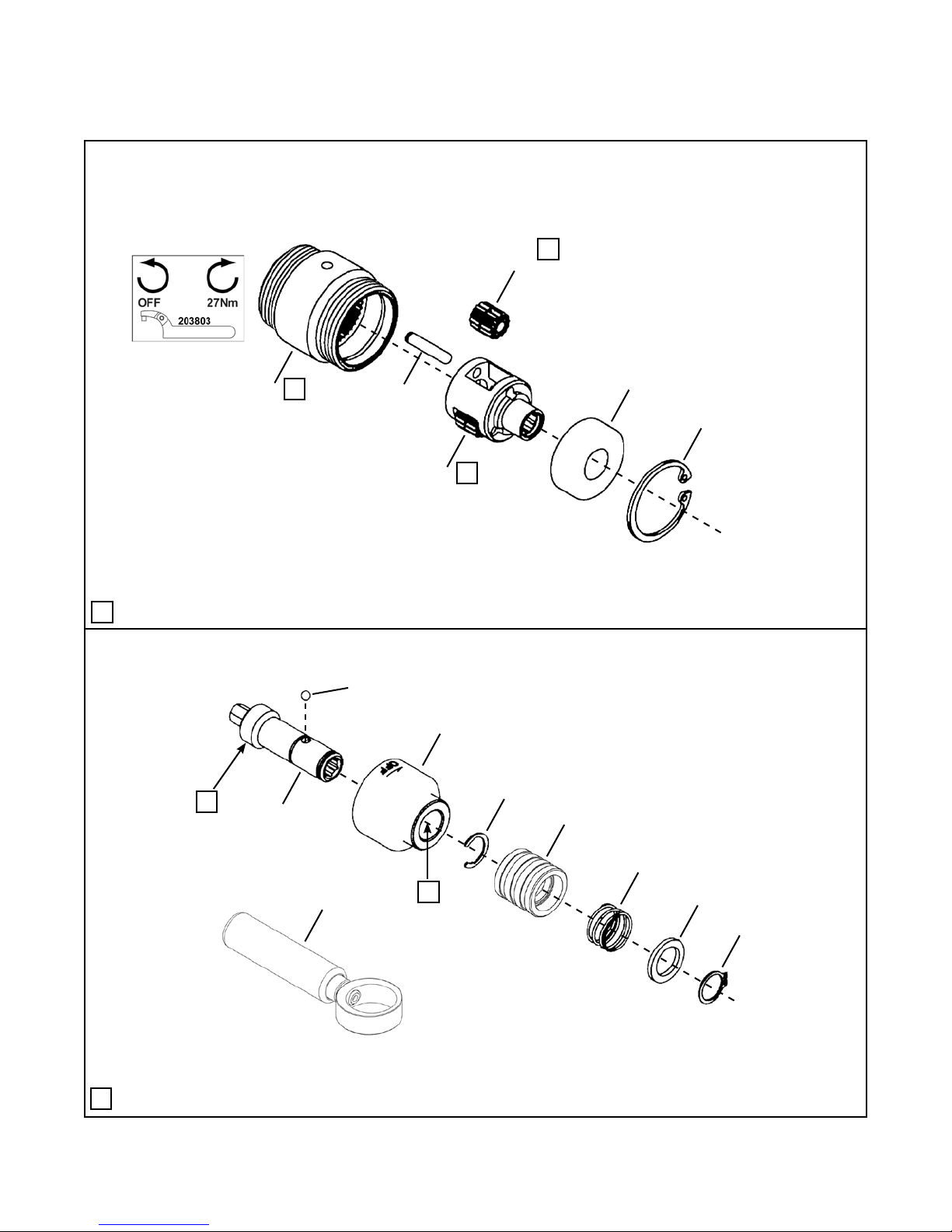
10.10 301991PT Clecomatic Clutch Assembly
301979PT Clecomatic Clutch Assembly
4
3
27*
7
8
1
L
2
9
5
6
14
14
10
12
12
Models
19(--)A02Q
19(--)A03Q
19(--)A04Q
19(--)A05Q
19(--)A06Q
L
11
13
14
L
15
16
Torque:
15 ft. lbs.
(20 Nm)
* Note: Not included with clutch assembly
17
18
20
21
22
23
24
19
26*
25*
Lubricate with 540450 Grease (18 oz. can)
L
Page 34

EN
Description
-- Table 10.10 1 Clutch Assembly
1 847411 1 3 O-Ring
2 207591PT 1 Clutch Cam
3 842980 13 26 Steel Ball (.094 diameter)
4 869149 1 3 Ball Retainer Plug
5 203613 1 3 Slide Reset Spring
6 203612 1 1 Trip Slide
7 207651PT 1 Dowel Pin
8 869112 1 Reset Pin
9 203585PT 1 3 Reset Spring
10 869424 1 Reset Pin Stop
1 1 207590PT 1 Clutch Spindle
12 842274 3 9 Steel Ball (.156 diameter)
13 844265 1 3 Steel Ball (.125 diameter)
14 842162 3 9 Steel Ball (.250 diameter)
15 207589PT 1 Driven Cam
16 Table 10.10 1 Torque Spring
17 207579PT 1 Lock Ring
18 869123 1 Adjustment Nut
19 203600PT 1 Spindle Bushing
20 619524 1 3 Retaining Ring
21 202833PT 1 1 Release Collar
22 202842PT 1 3 Release Collar Spring
23 864249 1 1 Release Collar Washer
24 833688 1 3 Release Collar Retaining Ring
25 207584PT 1 Clutch Housing (includes Ref. 26) (Not included in Clutch Assembly)
26 203584 1 Adjustment Cover (Not included in Clutch Assembly)
27 203586PT 1 2 Trip Rod (Not included in Clutch Assembly)
(#) Quantity
(X) Recommended Spare Parts (quantity shown based on 1-5 tools in operation)
10.10 301991PT Clecomatic Clutch Assembly
301979PT Clecomatic Clutch Assembly
Ref
Number
#
X
Cleco
Table 10.10
Ref. Description #
19(--)A02Q
19(--)A03Q
#
19(--)A04Q
19(--)A05Q
19(--)A06Q
-- Clutch Assembly 1 301991PT 1 301979PT
Clutch Spring (Green) 1 207652PT ------
Clutch Spring (White) ------ 1 207596PT
16
®
Spare Parts
PL12-1012EN
09/20/2012
Page 35

PL12-1012EN
09/20/2012
Cleco
®
Spare Parts
10.11 302017PT Clecomatic Clutch Assembly
4
3
27*
7
8
1
L
2
9
5
6
14
14
10
12
12
Models
19(--)A07Q
19(--)A09Q
L
11
13
14
L
15
16
Torque:
15 ft. lbs.
(20 Nm)
* Note: Not included with clutch assembly
17
18
20
21
22
23
24
19
26*
25*
Lubricate with 540450 Grease (18 oz. can)
L
Page 36

Cleco
EN
Description
-- 302017PT 1 Clutch Assembly
1 847411 1 3 O-Ring
2 207694PT 1 Clutch Cam
3 842980 13 26 Steel Ball (.094 diameter)
4 869149 1 3 Ball Retainer Plug
5 203613 1 3 Slide Reset Spring
6 203612 1 1 Trip Slide
7 207651PT 1 Dowel Pin
8 869112 1 Reset Pin
9 203585PT 1 3 Reset Spring
10 869424 1 Reset Pin Stop
1 1 207590PT 1 Clutch Spindle
12 842274 3 9 Steel Ball (.156 diameter)
13 844265 1 3 Steel Ball (.125 diameter)
14 842162 3 9 Steel Ball (.250 diameter)
15 207695PT 1 Driven Cam
16 207696PT 1 Torque Spring (Orange)
17 207579PT 1 Lock Ring
18 869123 1 Adjustment Nut
19 203600PT 1 Spindle Bushing
20 619524 1 3 Retaining Ring
21 202833PT 1 1 Release Collar
22 202842PT 1 3 Release Collar Spring
23 864249 1 1 Release Collar Washer
24 833688 1 3 Release Collar Retaining Ring
25 207584PT 1 Clutch Housing (includes Ref. 26) (Not included in Clutch Assembly)
26 203584 1 Adjustment Cover (Not included in Clutch Assembly)
27 Table 10.11 1 2 Trip Rod (Not included in Clutch Assembly)
(#) Quantity
(X) Recommended Spare Parts (quantity shown based on 1-5 tools in operation)
10.11 302017PT Clecomatic Clutch Assembly
Ref
Number
#
X
Table 10.11
Ref. Description # 19(--)A07Q # 19(--)A09Q
27 Trip Rod 1 203586PT 1 207704PT
®
Spare Parts
PL12-1012EN
09/20/2012
Page 37

PL12-1012EN
09/20/2012
Cleco
®
Spare Parts
10.12 301981PT Clecomatic Clutch Assembly
4
3
18*
7
8
1
L
2
5
6
13
13
Models
19(--)A15Q
12
9
10
L
11
12
13
L
14
15
16
* Note: Not included with clutch assembly
Lubricate with 540450 Grease (18 oz. can)
L
Torque:
15 ft. lbs.
(20 Nm)
17
19*
20*
21*
22*
Page 38

EN
Description
-- 301981PT 1 Clutch Assembly
1 847411 1 3 O-Ring
2 207591PT 1 Low Speed Clutch Cam
3 842980 13 26 Steel Ball (.094 diameter)
4 869149 1 3 Ball Retainer Plug
5 203613 1 3 Slide Reset Spring
6 203612 1 1 Trip Slide
7 207651PT 1 Dowel Pin
8 869112 1 Reset Pin
9 203585PT 1 3 Reset Spring
10 869424 1 Reset Pin Stop
1 1 207592PT 1 Clutch Spindle
12 842274 3 9 Steel Ball (.156 diameter)
13 842162 3 9 Steel Ball (.250 diameter)
14 207589PT 1 Low Speed Driven Cam
15 207596PT 1 Torque Spring (White)
16 207579PT 1 Lock Ring
17 869123 1 Adjustment Nut
18 203586PT 1 2 Trip Rod (Not included in Clutch Assembly)
19 207624PT 1 Clutch Housing (includes Ref. 20) (Not included in Clutch Assembly)
20 203584 1 Adjustment Cover (Not included in Clutch Assembly)
21 847095 1 2 Ball Bearing (Not included in Clutch Assembly)
22 619017 1 2 Retaining Ring (Not included in Clutch Assembly)
(#) Quantity
(X) Recommended Spare Parts (quantity shown based on 1-5 tools in operation)
10.12 301981PT Clecomatic Clutch Assembly
Ref
Number
#
X
Cleco
®
Spare Parts
PL12-1012EN
09/20/2012
Page 39
PL12-1012EN
09/20/2012
Cleco
®
Spare Parts
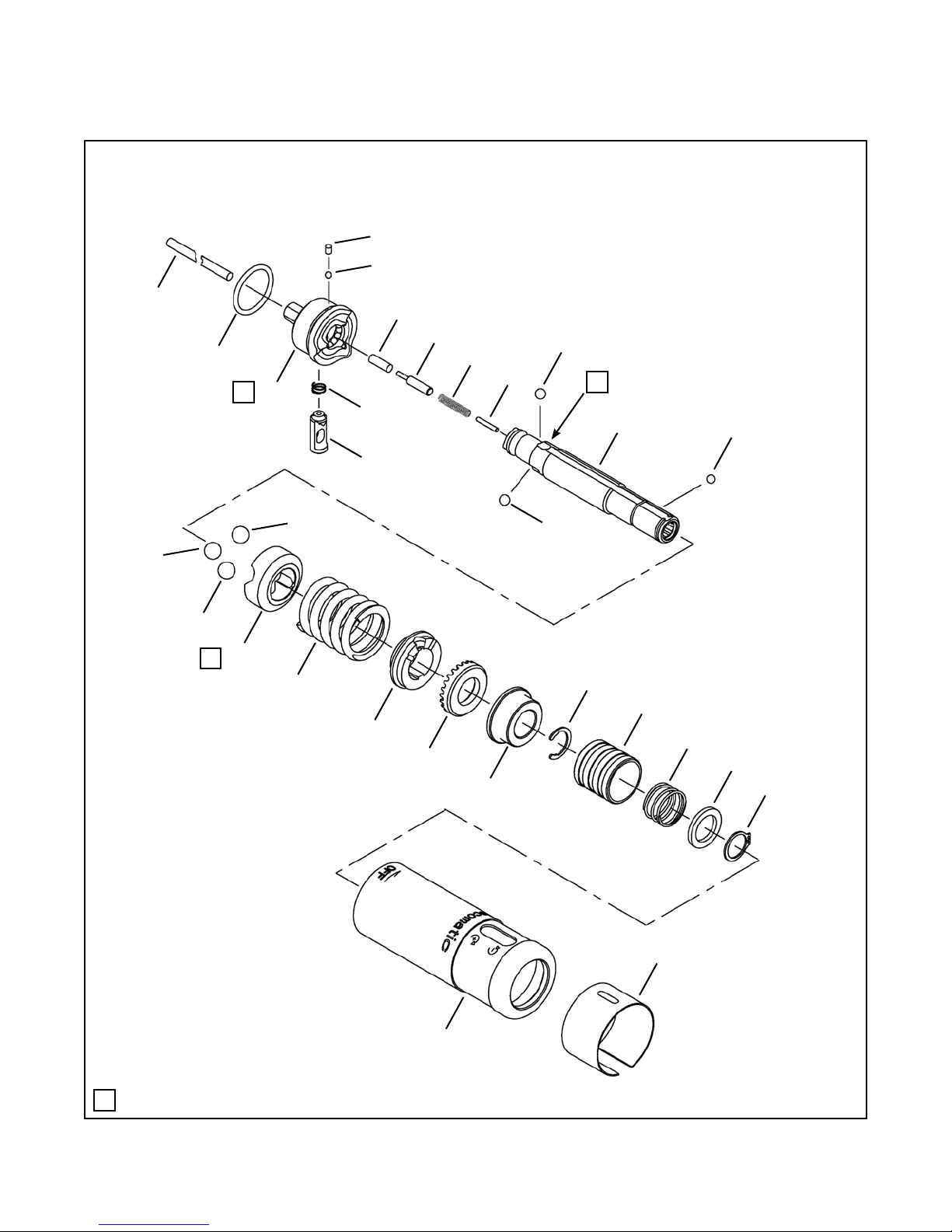
10.13 301124 Output Gear Assembly
L
1
6
Models
19PTA15Q
19TTA15Q
L
5
3
2
L
4
Lubricate with 540450 Grease (18 oz. can)
L
10.14 301122 Output Spindle Assembly
5
L
8
9
Not Shown to Scale
L
Models
19PTA15Q
19TTA15Q
7
6
3
4
2
1
Lubricate with 540450 Grease (18 oz. can)
L
Page 40

Cleco
EN
Description
1 207109 1 Gear Case
2 619017 1 2 Retaining Ring
3 847595 1 2 Ball Bearing
4 204282 1 Gear Cage
5 203623PT 3 6 Idler Gear (14T)
6 844111 3 6 Dowel Pin
(#) Quantity
(X) Recommended Spare Parts (quantity shown based on 1-5 tools in operation)
(T) Teeth
10.13 301124 Output Gear Assembly
Ref
Number
#
X
EN
Description
1 833688 1 2 Retaining Ring
2 864249 1 2 Washer
3 202833PT 1 Release Collar
4 202842PT 1 3 Spring
5 844265 1 3 Steel Ball (1/8")
6 619524 1 2 Retaining Ring
7 207104 1 Spindle Housing
8 202847PT 1 Spindle
9 301770 * 1 Dead Handle (Not included in Output Spindle Assembly)
(#) Quantity
(X) Recommended Spare Parts (quantity shown based on 1-5 tools in operation)
10.14 301122 Output Spindle Assembly
Ref
Number
#
X
* Note: 15Q models: Standard Equipment
All other models: Optional Equipment
®
Spare Parts
PL12-1012EN
09/20/2012
Page 41

PL12-1012EN
Trigger Allow Push-to-Start Clecomatic Clutch
19PC Series 19TC Series in-lb Nm in-lb Nm in-lb Nm in-lb Nm in mm lbs kg in mm lbs kg
19PCA02Q 19TCA02Q 19 2.1 5 0.6 19 2.1 5 0.6 2800 8.1 206 1.41 0.6 8.0 202 1.44 0.7
19PCA03Q 19TCA03Q 26 2.9 5 0.6 19 2.1 5 0.6 1900 8.3 2 1 1 1.51 0.7 8.2 207 1.54 0.7
19PCA04Q 19TCA04Q 40 4.5 10 1.1 38 4.3 10 1.1 1100 8.1 206 1.41 0.6 8.0 202 1.54 0.7
19PCA05Q 19TCA05Q 45 5.1 10 1.1 38 4.3 10 1.1 660 8.5 216 1.51 0.7 8.4 212 1.54 0.7
19PCA06Q 19TCA06Q 45 5.1 10 1.1 38 4.3 10 1.1 260 8.5 216 1.51 0.7 8.4 212 1.54 0.7
19PCA07Q 19TCA07Q 60 6.8 15 1.7 60 6.8 24 2.7 660 8.5 216 1.51 0.7 8.4 212 1.54 0.7
19PCA09Q 19TCA09Q 79 8.9 15 1.7 79 8.9 24 2.7 470 9.8 248 1.65 0.7 9.3 235 1.73 0.8
19TC Series
Length
Weight
Model Number
Free
Speed
(rpm)
19PC Series
Length
Weight
Tool Range
Max Tq
Min Tq
With Std. Spring
Max Tq
Min Tq
Trigger Start Clecomatic Clutch
19PT Series 19TT Series in-lb Nm in-lb Nm in-lb Nm in-lb Nm in mm lbs kg in mm lbs kg
19PTA02Q 19TTA02Q 19 2.1 5 0.6 19 2.1 5 0.6 2800 8.0 204 1.41 0.6 7.9 199 1.44 0.7
19PTA03Q 19TTA03Q 26 2.9 5 0.6 19 2.1 5 0.6 1900 8.2 209 1.51 0.7 8.1 204 1.54 0.7
19PTA04Q 19TTA04Q 40 4.5 10 1.1 38 4.3 10 1.1 1100 8.0 204 1.41 0.6 7.9 199 1.54 0.7
19PTA05Q 19TTA05Q 45 5.1 10 1.1 38 4.3 10 1.1 660 8.4 214 1.51 0.7 8.3 210 1.54 0.7
19PTA06Q 19TTA06Q 45 5.1 10 1.1 38 4.3 10 1.1 260 8.4 214 1.51 0.7 8.3 210 1.54 0.7
19PTA07Q 19TTA07Q 60 6.8 15 1.7 60 6.8 24 2.7 660 8.4 214 1.51 0.7 8.3 210 1.54 0.7
19PTA09Q 19TTA09Q 79 8.9 15 1.7 79 8.9 24 2.7 470 9.8 248 1.65 0.7 9.3 235 1.73 0.8
19PTA15Q 19TTA15Q 130 14.7 45 5.1 130 14.7 45 5.1 260 9.7 247 1.81 0.9 9.6 243 1.94 0.9
Length
Weight
Length
Weight
Model Number
Tool Range
With Std. Spring
Free
Speed
(rpm)
19PT Series
19TT Series
Max Tq
Min Tq
Max Tq
Min Tq
09/20/2012
Cleco
Technical Data
11 Technical data
11.1 19PCA and 19TCA Specications
11.2 19PTA and 19TTA Specications
®
Page 42

12 Service
12.1 Replacement parts
Use only original Cleco replacement parts. Failure to comply can result in reduced power and increased
service requirements. The tool warranty may be voided if replacement parts are not manufactured or
approved by Apex Tool Group.
12.2 Tool repairs
Only qualied and trained personnel are to repair this equipment.
12.3 Warranty repairs
All warranty repairs are to be performed by an authorized Apex Tool Group service center. Contact your
local representative for assistance with warranty repair claims.
Cleco
Service
®
PL12-1012EN
09/20/2012
Page 43

PL12-1012EN
09/20/2012
13 Disposal
---------------------------------------------------------------------------------------------------------------------------------------
Injuries and environmental damage from improper disposal.
Components and auxillary materials of the tool pose risks to health and the environment.
ÚCapture auxillary materials (oils, greases) when drained and dispose of them properly.
ÚSeparate the packaging components and dispose of them properly.
ÚComply with all applicable local regulations.
Observe local disposal guidelines for all components of this tool and its packaging.
---------------------------------------------------------------------------------------------------------------------------------------
Cleco
Disposal
®
Page 44

PL12-1012EN
09/20/2012
Page 45


Sales & Service Centers
Note: All locations may not service all products. Please contact the nearest Sales & Service Center for
the appropriate facility to handle your service requirements.
Detroit, MI Houston, TX Lexington, SC Los Angeles, CA
Apex Tool Group Apex Tool Group Apex Tool Group Apex Tool Group
Sales & Service Center Sales & Service Center 670 Industrial Drive Sales & Service Center
2630 Superior Court 6550 West Sam Houston Lexington, SC 29072 15503 Blackburn Avenue
Auburn Hills, MI 48326 Parkway North, Suite 200 Tel: 800-845-5629 Norwalk, CA 90650
Tel: 248-391-3700 Houston, TX 77041 Tel: 803-951-7544 Tel: 562-623-4457
Fax: 248-391-7824 Tel: 713-849-2364 Fax: 803-358-7681 Fax: 562-802-1718
Fax: 713-849-2047
Seattle, WA York, PA Canada Germany
Apex Tool Group Apex Tool Group Apex Tool Group Apex Tool Group
Sales & Service Center Sales & Service Center Sales & Service Center GmbH & Co. OHG
2865 152nd Avenue N.E. 3990 East Market Street 5925 McLaughlin Road Industriestraße 1
Redmond, WA 98052 York, PA 17402 Mississauga, Ont. L5R 1B8 73463 Westhausen
Tel: 425-497-0476 Tel: 717-755-2933 Canada Germany
Fax: 425-497-0496 Fax: 717-757-5063 Tel: 905-501-4785 Tel: +49 (0) 73 63 81 0
Fax: 905-501-4786 Fax: +49 (0) 73 63 81 222
England France China Mexico
Apex Tool Group Apex Tool Group SAS Cooper (China) Co., Ltd. Cooper Tools
GmbH & Co. OHG 25 rue Maurice Chevalier a company of de México S.A. de C.V.
C/O Spline Gauges 77330 Ozoir-La-Ferrière Apex Tool Group, LLC a company of
Piccadilly, Tamworth France 955 Sheng Li Road, Apex Tool Group, LLC
Staffordshire B78 2ER Tel: +33 1 6443 2200 Heqing Pudong, Shanghai Vialidad El Pueblito #103
United Kingdom Fax: +33 1 6443 1717 China 201201 Parque Industrial Querétaro
Tel: +44 1827 8741 28 Tel: +86-21-28994176 Querétaro, QRO 76220
Fax: +44 1827 8741 28 Fax: +86-21-51118446 Mexico
Tel: +44 1827 8741 28 Tel: +52 (442) 211-3800
Fax: +52 (442) 103-0443
Brazil Hungary
Cooper Tools Industrial Ltda. Cooper Tools Hungaria Kft.
a company of a company of
Apex Tool Group, LLC Apex Tool Group, LLC
Av. Liberdade, 4055 Berkenyefa sor 7
Zona Industrial - Iporanga Pf: 640
18087-170 Sorocaba 9027 Györ
SP Brazil Hungary
Tel: +55 15 2383929 Tel: +36 96 66 1383
Fax: +55 15 2383260 Fax: +36 96 66 1135
Apex Tool Group, LLC
1000 Lufkin Road
Apex, NC 27539
Phone: 919-387-0099
Fax: 919-387-2614
www.apextoolgroup.com
PL12-1012EN/Printed in USA 09/2012/Copyright © Apex Tool Group, LLC
 Loading...