

Cleaver Scientific powerPRO Series, powerPRO500, powerPRO300, powerPRO3AMP Instruction Manual
Page 1
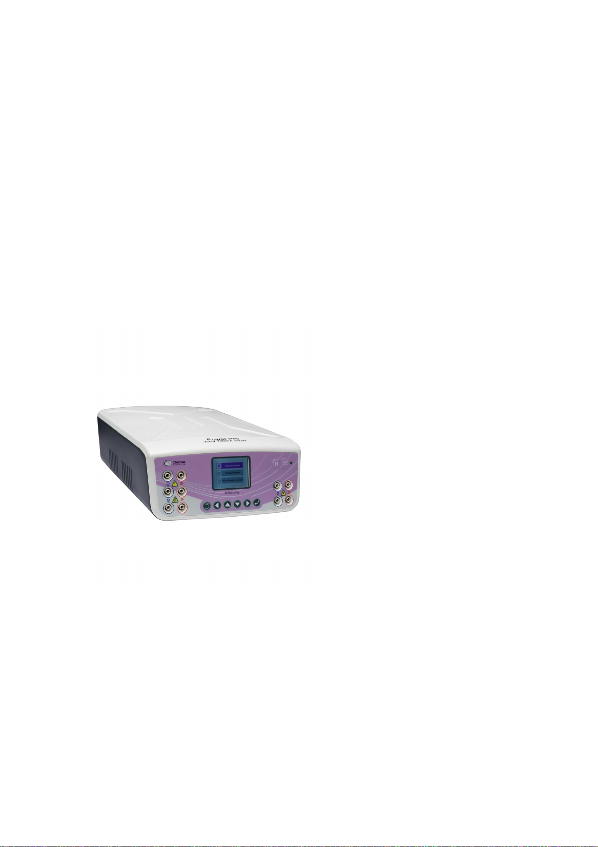
POWERPRO
Page 2

Page 3

powerPRO Series
Power Supplies
Instruction Manual
Catalogue Numbers
powerPRO300
powerPRO500
powerPRO3AMP
Record the following for your records:
Model _____________________
Catalogue No. _____________________
Date of Delivery _____________________
Warranty Period _____________________
Serial No. _____________________
Invoice No. _____________________
Purchase Order No. _____________________
13/11/2018 Page 1
Page 4

Contents
Instruction Manual 1
Catalogue Numbers 1
Contents 2
Safety Information 3
Precautions 4
Environmental Conditions 4
Avoiding Electrical Shock 4
Avoiding Damage to the Instrument 4
Equipment Operation 5
Symbols 5
Potential Risk and Preventive Measures 6
Risk assessment table 6
Preventative measures 6
Packing List 7
Specifications 8
Operating Instructions 10
Installation 10
Control Interface 10
Operation 11
Constant Mode 11
Program Mode 13
Typical Running Conditions 14
Troubleshooting 16
Care and Maintenance 18
Replacing the Fuses 18
Maintenance 18
Ordering information 18
Warranty 19
13/11/2018 Page 2
Page 5

Safety Information
Cleaver Scientific powerPRO Power Supply has been tested and found to
comply with the limits for the CE regulation. Also, it is RoHS compliant to deliver
confident product which meets the environmental directive. These limits are
designed to provide reasonable protection against harmful interference when
the instrument series is operated in a commercial environment. This instrument
series used together with power supply unit generates, uses, and can radiate
radio frequency energy, and if not installed and used in accordance with the
instruction manual, may cause harmful interference to radio communications.
Operation of this instrument series in a residential area is likely to cause harmful
interference in which case the user will be required to correct the interference
at their expense. Changes or modifications not expressly approved by the
party responsible for compliance could void the user’s authority to operate
the equipment. It is strongly recommended for the user to read the following
points carefully before operating this equipment.
1. Read and follow the manual instructions carefully.
2. Do not alter the equipment. Failure to follow these directions could
result in personal and/or laboratory hazards, as well as invalidate
equipment warranty.
3. Use a properly grounded electrical outlet with correct voltage and
current handling capacity.
4. Disconnect from power supply before maintenance and servicing.
Refer servicing to qualified personnel.
5. Never use this instrument series without having the safety cover
correctly in position.
6. Do not use the unit if there is any sign of damage to the external tank
or cover. Replace damaged parts.
7. Do not use in the presence of flammable or combustible material;
fire or explosion may result. This device contains components which
may ignite such materials.
8. Refer maintenance and servicing to qualified personnel.
9. Ensure that the system is connected to electrical service according
to local and national electrical codes. Failure to make a proper
connection may create fire or shock hazard.
10. Use appropriate materials and operate correctly to avoid possible
hazards of explosion, implosion or release of toxic or flammable
gases arising from overheated materials.
11. The unit shall be operated only by qualified personnel.
13/11/2018 Page 3
Page 6

Precautions
Use high level of precaution against any electrical device. Before connecting
the electrical supply, check to see if the supply voltage is within the range
stated at the rating label, and see to it that the device be seated firmly. Place
the unit in a safe and dry location; it must NOT touch the surrounding. Follow
the safety precautions for chemicals / dangerous materials. If needed, please
contact qualified service representative or support@cleaverscientific.com
Environmental Conditions
Ensure the instrument is installed and operated strictly under the following
conditions:
1. Indoor use only
2. ≤95% RH
3. 75 kPa – 106 kPa
4. Altitude must not exceed 2000 meters
5. 4℃~ 40℃ operating temperature
6. Pollution degree: 2
7. Mains supply voltage fluctuations up to ±10% of the normal voltage
Avoiding Electrical Shock
Follow the guidelines below to ensure safe operation of the unit.
The powerPRO Power Supply has been designed to utilize shielded wires thus
minimizing any potential shock hazard to the user. Cleaver Scientific
recommends against the use of unshielded wires.
To avoid electrical shock:
1. In the event of solution spilling on the instrument, it must be dried out for
at least 2 hours and restored to NORMAL CONDITION before each
operation.
2. Never connect or disconnect wires loading from the power jacks when
the red indicator light of power switch is on.
3. WAIT at least 5 seconds after stopping a run before handling output leads
or any connected apparatus.
4. ALWAYS make sure that your hands, work area, and instruments are
clean and dry before making any connections or operating the power
supply.
5. ONLY connect the power cord to a properly grounded AC outlet.
Avoiding Damage to the Instrument
1. Do not attempt to operate the device if damage is suspected.
2. Protect this unit from physical damage, corrosive agents and
extreme temperatures (direct sunlight, etc.).
3. For proper ventilation and safety concerns, keep at least 10 cm of
13/11/2018 Page 4
Page 7

space behind the instrument, and at least 5 cm of space on each
Indicates an area where a potential shock hazard may
Consult the manual to avoid possible personal injury or
throw this unit into a municipal trash bin when
this unit has reached the end of its lifetime. To ensure
utmost protection of the global environment and
side.
4. Use high level of precaution against the damages on the unit.
5. Do not operate the unit out of environmental conditions addressed
above.
6. Do not operate the power supplies in high humidity environments (>
95%), or where condensation may occur.
7. To avoid condensation after operating the power supply in a cold
room, wrap the unit in a plastic bag and allow at least 2 hours for the
unit to equilibrate to room temperature before removing the bag
and operating the unit.
8. Prior to applying any cleaning or decontamination methods other
than manufacturer’s recommendation, users should check with the
manufacturer’s instruction to see if the proposed method will
damage the equipment.
Equipment Operation
Follow the guidelines below to ensure safe operation of the unit:
1. NEVER access dangerous chemicals or other materials to prevent
possible hazard of explosion and damage.
2. Do not operate the unit without lids or covers to prevent possible
hazards.
3. A temporary conductivity caused by condensation might occur
even though this series is rated Pollution Degree 2 in accordance
with IEC 664.
Symbols
Symbols used on the power supply are explained below.
exist.
instrument damage.
Indicates disposal instruction.
DO NOT
minimize pollution, please recycle this unit.
13/11/2018 Page 5
Page 8
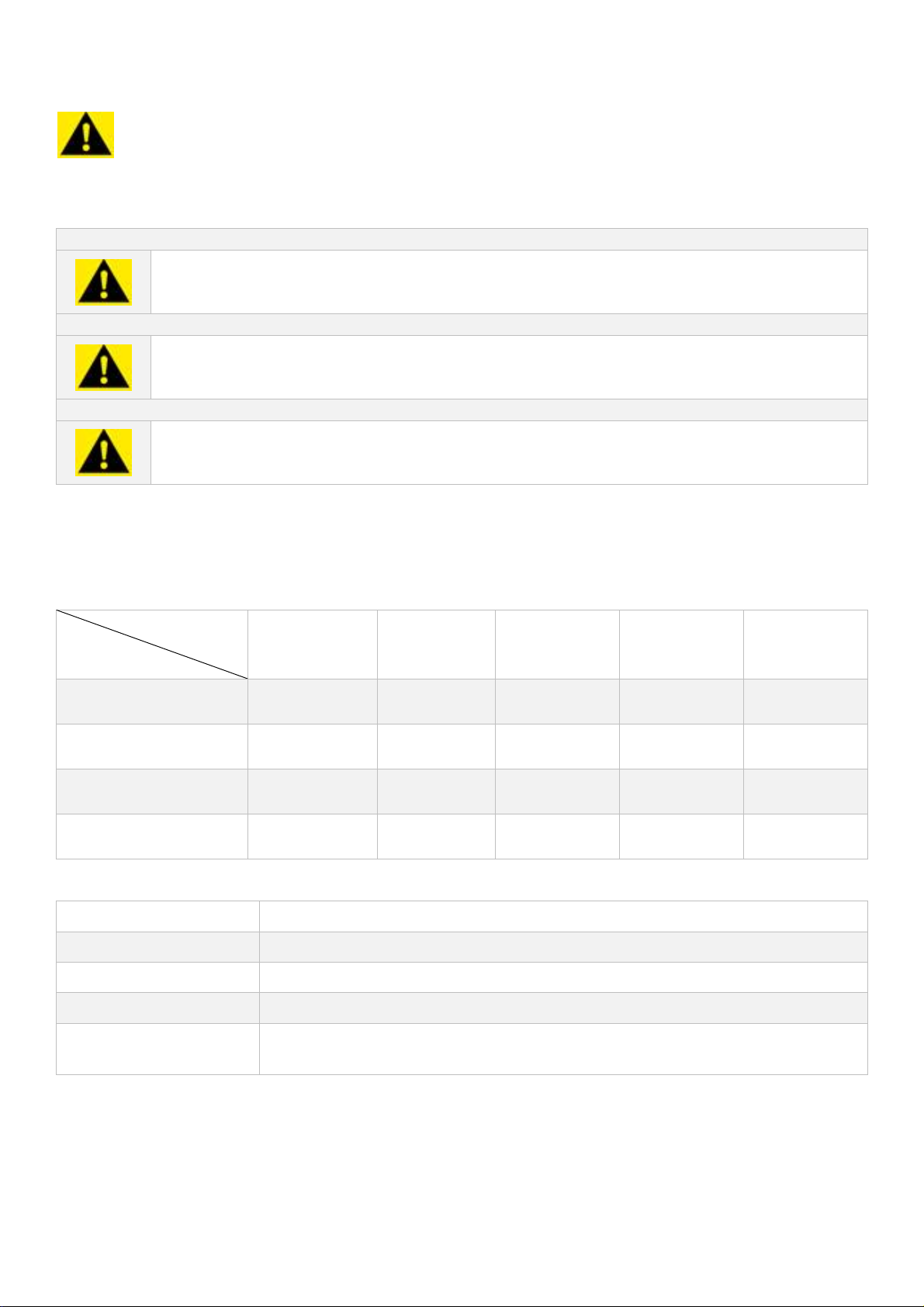
Caution/ Warning: Indicates a hazardous situation
which, if not avoided, could result in death or serious
injury.
powerPRO 300
Max. voltage: 300 V
Max. current: 700 mA
Max. watt: 150 W
powerPRO 3AMP
Max. voltage: 300 V
Max. current: 3000 mA
Max. watt: 300 W
powerPRO 500
Max. voltage: 500 V
Max. current: 800mA
Max. watt: 300W
Potential Risk and Preventive Measures
Risk assessment table
Frequency
Risk
Bruise √
Slash √
Electrical shock √
Power cord plug
wrong
Frequent Likely Possible Rare Unlikely
√
Preventative measures
Potential Risk Preventive measures
Bruise Do not put the machine near the table edge.
Slash Prevent hard impact on the case.
Electrical Shock Make sure that your hands, work area, and devices are clean and dry
Power cord plug
wrong
13/11/2018 Page 6
Observe correct adapter plug.
Page 9

Packing List
powerPRO 300
1x powerPRO 300 Power Supply
1x Power Cord
1x Instruction Manual
powerPRO 3AMP
1x powerPRO 3AMP Power Supply
1x Power Cord
1x Instruction Manual
powerPRO 500
1x powerPRO 500 Power Supply
1x Power Cord
1x Instruction Manual
Packing List Checked by: ________________________
Date: ________________________
The packing lists should be referred to as soon as the units are received to
ensure that all components have been included. The unit should be checked
for damage when received.
Cleaver Scientific is liable for all missing or damaged parts / accessories within
7 days after customer received this instrument package. Please contact
Cleaver Scientific immediately regarding this issue. If no response within such
period from consignee party, that will be consignee party’s whole
responsibility.
Please contact your supplier if there are any problems or missing items.
13/11/2018 Page 7
Page 10

Specifications
℃
powerPRO 300 powerPRO 3AMP powerPRO 500
Output Voltage / Inc 5 - 300V / 1V 5 – 300 / 1V 5 – 500 / 1V
Output Current / Inc 1 - 700mA / 1mA 10 – 3,000mA / 10mA 1 – 800mA / 1mA
Max. Watt 150W 300W 300W
Rated Voltages 100~ 240V; 47-60Hz,
200W: T2.5A/250V
Type of Output 1. Voltage or Current with automatic crossover
2. When target constant mode is set, system automatically adjusts the
two other parameter to maximum to allow constant run (later could be
changed by user)
Program Storage 30 programmed files
Program Multi-Step Up to 6 steps
Editable Program
Function
Display 2.4” TFT
Control Microprocessor controller
Safety Device No Load detect
1.Have typical running conditions program
2.Manual editable program
Leakage detect
Over temperature protection
100-240V: 4760Hz,410W: T4A/250V
100-240V: 4760Hz,400W: T4A/250V
Over load detection
Sudden load change detection (could be disabled by proper setting)
Shrouded plugs and sockets
Timer Constant: 1~999 mins with alarm, continuous
Program: 1~999 mins with alarm, continuous
Crossover Yes
Stackable Yes
Automatic Recovery
After Power Failure
IQ/OQ Protocols Yes, optional
Regulatory CE, ETL CE CE
Operating
Temperature
Construction Material Flame retardant ABS faceplate
Yes
4℃~ 40
13/11/2018 Page 8
Page 11

Unit Dimension 215 x 335 x 104 mm (W x L x H)
Weight approx. 2.1 kg
Cleaver Scientific powerPRO Series Power Supply are microprocessor
controlled and designed to meet most electrophoresis needs. This manual
describes the setup and operation of the powerPRO Series Power Supply
including important information on safety and maintenance of the unit. The
powerPRO Series Power Supply are capable of running horizontal & vertical
electrophoresis, SDS-PAGE, native PAGE applications, two-dimensional
electrophoresis, and electro-blotting. Furthermore, the powerful specifications
plus five terminal pairs can be used for multi electrophoresis units
simultaneously.
Cleaver Scientific powerPRO Series Power Supply provides Constant Voltage
or Constant Current or Constant Power to instruments used in electrophoresis.
5 terminal pairs and the powerful specification equipped enable the
maximum capability of powerPRO Series Power Supply compared to other
existing similar product on the market.
Features of powerPRO Series Power Supply:
Compact size
Microprocessor controller
Constant voltages, constant currents and constant power
Five terminal outlets
LCD display
Timer with alarm function
Advanced safety devices
Stackability
Wide applications for DNA, RNA and protein electrophoresis
13/11/2018 Page 9
Page 12

Operating Instructions
Installation
powerPRO Series Power Supplies require no complex installation. As long as
the unit is placed on a sturdy and level surface in a safe, dry place, and further
connects with well-prepared electrophoresis systems, it is ready for operation.
Control Interface
Start Key: Press to activate or stop
the unit
Pause Key: Press to temporarily
interrupt power to an operation in
progress; resume power after
pausing without resetting the timer
Settings Key: Press to select either
Constant/ Program Mode or
Constant Voltage or Constant
Current mode or Time
Enter Key: Press to enter the
numeric value set up
Press to move cursor left between
parameters
Press to move cursor right between
parameters
Press to move cursor up between
parameters and to increase
numeric values
Press to move cursor down
between parameters and to
decrease numeric values
13/11/2018 Page 10
Page 13

Operation
1. Place the unit on a sturdy and level surface in a safe, dry place,
away from laboratory traffic.
2. Ensure that the AC power switch is OFF, and then plug the threepronged power cord one end into a grounded three-prong AC
outlet with appropriate voltage (100V to 240V as indicated on the
rating sticker near the AC cord on the back of the unit) and plug the
other end into the main power socket.
3. Connect the DC output jacks from the electrophoresis unit; insert the
red lead (+) into the red output jack, and the black lead (-) into the
black output jack.
4. Power on the unit by pressing the ON/OFF switch on the back.
5. The screen will show a loading screen for few seconds then enter to
the mode-selecting page.
Constant Mode
Use the Constant Voltage / Current / Power Operation for applications that
require only one specific voltage limit, current limit, and power limit
continuously during the entire operation of electrophoresis.
Note: When target constant mode is set, system automatically adjusts the other two
parameters to maximum to allow constant run. For example, if constant voltage is set,
system will adjust current and power to the maximum value.
Users could later lower the other two values by themselves. System will hold the value either
at target constant value or the one which has been reached first
1. Use the up and down arrow keys to select
constant mode, then press the enter key to
move to the next page.
13/11/2018 Page 11
Page 14

2. Use the up and down arrows to select
which parameter should be kept constant.
Press the enter key to move to the next
page.
3. Use the up and down arrows to navigate
the parameters, press the enter key to start
parameter adjustment.
4. Use the up and down arrows to adjust
parameter values, then press the enter key
to confirm.
Note: If the time value is set “0,” it indicates the power
supplier will constantly operate until user manually stops it.
5. Press the start Key to begin electrophoresis.
The LED next to the start key will light,
indicating the power supply is active.
Parameter values can be viewed during the run.
6. Pressing the pause key will temporarily
pause the run and will allow parameter
values to be altered using the same
method outlined above.
Pressing the start key will resume the run
7. Upon completion of the run, an alarm will
sound, and the screen will display
“Complete”.
8. Press the start key to terminate the run and
press the setting key to return to the
settings screen.
13/11/2018 Page 12
Page 15

Program Mode
The Program Mode allows you to vary levels in voltage (V), current (mA), and
power (W) during specified time periods for up to 6 Steps, depending upon
your electrophoresis needs. The powerPRO Series power supply is capable of
having 30 different program files storages for user’s convenience. After starting
the operation, set the Program Mode as follow:
1. Use the up and down arrow keys to select
program mode, then press the enter key to
move to the next page.
2. Use the up and down arrows to select the
desired program. Press the enter key to
move to the next page.
3. Use the up, down left and right arrows to
navigate the parameters, press the enter key
to start parameter adjustment.
4. Use the up and down arrows to adjust
parameter values, then press the enter key
to confirm.
5. Navigate using the down arrow to set
parameters for step 5 and 6.
13/11/2018 Page 13
Page 16

6. Press the start Key to begin electrophoresis.
The LED next to the start key will light,
indicating the power supply is active.
Parameter values can be viewed during the run.
7. Pressing the pause key will temporarily pause
the run and will allow parameter values to
be altered using the same method outlined
above.
Pressing the start key will resume the run
8. Upon completion of the run, an alarm will
sound, and the screen will display
“Complete”.
9. Press the start key to terminate the run and
press the setting key to return to the settings
screen.
Typical Running Conditions
Besides Constant Mode and Program Mode, powerPRO Power Supply provide
a third option, Typical Running Condition. It is helpful for those users who are
not familiar with the parameter settings and is convenience for a quick start.
1. Use the up and down arrow keys to select
typical running conditions mode, then press
the enter key to move to the next page.
13/11/2018 Page 14
Page 17

2. There are 4 categories that can be selected. Choose the model
according to your experiment need.
3. After selecting model, the pre-set value will display. These values can
be adjusted as described previously.
4. Press the start button to begin electrophoresis.
13/11/2018 Page 15
Page 18

Troubleshooting
Many operating problems may be solved by carefully reading and following
the instructions in this manual accordingly. Some suggestions for
troubleshooting are given below. Should these suggestions not resolve the
problem, contact our service department or a distributor in your region for
assistance. If troubleshooting service is required, please include a full
description of the problem.
Problem Possible Causes Solution
No Display / lights No AC power Check if powerPRO power supply is
plugged, or AC power source has
problem.
AC power cord is not
connected
The fuse has blown Replace the fuse.
Repeated fuse broken Hardware failure Contact Cleaver Scientific service
Operation stops and
the screen displays
Operation stops with
alarm: The screen
displays
Communication wires on
circuit board have loosen
or broken.
Electrophoresis leads are
not connected to the
power supply or to the
electrophoresis unit(s), or
there is a broken circuit in
the electrophoresis cell
High resistance due to
tape left on a pre-cast
gel, incorrect buffer
concentration, or
incorrect buffer volumes
in the electrophoresis cell
Check AC power cord connections at
both ends. Use the correct cords.
department
It is recommended to send the machine
back to local distributor or our Service
Department for maintenance.
Check the connections to the power
supply and on your electrophoresis cell to
make sure the connection is intact; check
condition of wires in electrophoresis unit.
Close the circuit by reconnecting the
cables. Press START/STOP to restart the run.
Make sure the tape is removed from the
pre-cast gel, buffers are prepared
correctly, and the recommended volume
of buffer is added to the electrophoresis
unit.
High voltage application
is set to run on a very low
current
Operation stops with
alarm. Display shows
13/11/2018 Page 16
Bad connections for
terminal connectors or
damaged wires or
damaged platinum wires
DISABLE No Load alarm on the Display
Screen
Check all the connections to terminators,
cables, wires, and gel tanks
Page 19

Operation stops with
alarm:
Display shows
Circuit is interrupted Verify that the running buffer is correct.
Verify the all cables are attached
correctly
Turn the Power switch off and on again;
restart application.
If you cannot restart the instrument, turn
off the power, disconnect the power cord
from the outlet, and contact Technical
Service.
Operation stops with
alarm:
Display shows
Operation stops with
alarm:
Display shows
Operation stops with
alarm:
Display shows
Circuit is interrupted Verify that the running buffer is correct.
Verify the all cables are attached
correctly
Turn the Power switch off and on again;
restart application.
If you cannot restart the instrument, turn
off the power, disconnect the power cord
from the outlet, and contact Technical
Service.
Ground leak detected
during run
Check the electrophoresis system for
improper grounding. Restart the power
supply by turning the Power switch off and
on.
Power supply is
overheating
Turn off power supply. Check for sufficient
airflow around the power supply fan. After
cooling down, restart the power supply by
turning the Power switch to the on
position.
If you cannot restart the instrument, turn
off the power, disconnect the power cord
from the outlet, and contact Technical
Service.
Warning message
displays with 5-second
beep sound.
The screen shows
The power once been cut
and now recover
User does not need to take extra action.
The warning sign and beep sound would
only last for 5 second; after that, the
machine will continue running the
unfinished project.
The sign indicates the machine has
been interrupted by sudden power off.
Press Enter Key to clear the sign.
13/11/2018 Page 17
Page 20

Care and Maintenance
Replacing the Fuses
1. Turn off the main power switch at the rear of Power Supply and
detach the power cord.
2. Open the fuses compartment located inside the Power Entry Module
by inserting a small flat blade screwdriver into the slot above the
ON/OFF switch. Turn the screwdriver to gently pry open the fuses
compartment.
Note: The fuses compartment will not open with the power cord in place.
1. Pull the fuses holder out of the compartment and inspect the fuses.
If the fuses are burned or there is a break in the fuses element,
replace the fuses with identical type of fuses.
2. Place the fuses holder back into the compartment.
3. Snap the cover closed.
For additional fuses, contact Cleaver Scientific
Maintenance
powerPRO Series Power Supply uses all solid-state components and should
require no maintenance or recalibration under normal use. If the unit must be
returned for repair, contact our service department or your local distributor for
shipping instruction.
Ordering information
Cat. No. Description
PowerPro300 300V, 700mA, 150W Power Supply
PowerPro3AMP 300V, 3000mA, 300W Power Supply
PowerPro500 500V, 800mA, 300W Power Supply
13/11/2018 Page 18
Page 21

Warranty
The Cleaver Scientific Ltd. (CSL) powerPRO units have a warranty against
manufacturing and material faults of twelve months from date of customer
receipt.
If any defects occur during this warranty period, CSL will repair or replace the
defective parts free of charge.
This warranty does not cover defects occurring by accident or misuse or
defects caused by improper operation.
Units where repair or modification has been performed by anyone other
than CSL or an appointed distributor or representative are no longer under
warranty from the time the unit was modified.
Units which have accessories or repaired parts not supplied by CSL or its
associated distributors have invalidated warranty.
CSL cannot repair or replace free of charge units where improper solutions or
chemicals have been used. For a list of these please see the Care and
Maintenance subsection.
If a problem does occur, then please contact your supplier or Cleaver
Scientific Ltd:
Cleaver Scientific Ltd.
Unit 41, Somers Road Industrial Estate
Rugby, Warwickshire, CV22 7DH
Tel: +44 (0)1788 565300
Email: info@cleaverscientific.com
13/11/2018 Page 19
Page 22

Page 23

Page 24

 Loading...