

Page 1
Cleaver Scientific Thermal Cycler
Cleaver Scientific Thermal Cycler
GTC96S /GTC96S-230
Operation Manual
Ver.2.1
Cleaver Scientific
Page 2

Notice
This instrument is licensed for research and development and for uses
other than human in vitro diagnostics.
Page 3

Cleaver Scientific Thermal Cycler
Table of Contents
SAFETY PRECAUTIONS ................................................................................................ 1
GENERAL DESCRIPTION ............................................................................................. 2
2.1 FEATURES ........................................................................................................................ 2
2.2 PRODUCT OVERVIEW ....................................................................................................... 2
GETTING STARTED ........................................................................................................ 6
3.1 UNPACKING ..................................................................................................................... 6
3.2 INITIAL OPERATION ......................................................................................................... 6
3.3 HEATED LID .................................................................................................................... 6
3.4 LID OPENING/CLOSING ................................................................................................... 7
3.5 FUNCTION MAP ............................................................................................................. 10
3.6 KEY ENTRY SYSTEM ..................................................................................................... 11
3.7 LOADING THE REACTION VESSEL .................................................................................. 11
USER FOLDER MANAGEMENT ................................................................................ 12
4.1 VIEWING A USER FOLDER .............................................................................................. 12
4.2 CREATING A NEW USER FOLDER ................................................................................... 13
4.3 EDITING A USER FOLDER ............................................................................................... 13
4.4 DELETING A USER FOLDER ............................................................................................ 13
PROTOCOL MANAGEMENT ...................................................................................... 15
5.1 RUNNING A PROTOCOL .................................................................................................. 15
5.2 PAUSE A PROTOCOL ....................................................................................................... 16
5.3 VIEWING RUNNING PROTOCOL INFORMATION ............................................................... 16
5.4 TERMINATING A PROTOCOL ........................................................................................... 17
CREATING A NEW PROTOCOL ................................................................................. 18
6.1 CHANGING TEMPERATURE/TIME VALUES ...................................................................... 18
6.2 INSERTING/DELETING TEMPERATURE SEGMENT ........................................................... 19
6.3 CHANGING TEMPERATURE SEGMENT COUNT (TEMP) AND CYCLE COUNT (CYC) .......... 19
6.4 ADVANCED SETTINGS .................................................................................................... 19
6.5 SAVING A PROTOCOL ..................................................................................................... 23
EDITING(VIEWING) A PROTOCOL .......................................................................... 24
DELETING A PROTOCOL ........................................................................................... 24
SYSTEM SETUP ............................................................................................................. 25
Page 4

9.1 DATA LOG ..................................................................................................................... 26
9.2 DATE & TIME ................................................................................................................ 27
9.3 LID TEMPERATURE ........................................................................................................ 27
9.4 BEEPER ......................................................................................................................... 28
9.5 ADMINISTRATOR ........................................................................................................... 28
9.6 SERVICE MODE ............................................................................................................. 28
9.7 RAMPING SPEED ............................................................................................................ 28
9.8 TM CALCULATOR .......................................................................................................... 29
MAINTENANCE AND TROUBLESHOOTING ......................................................... 30
10.1 CLEANING THE UNIT .................................................................................................... 30
10.2 CLEANING THE HEATED LID ......................................................................................... 30
10.3 REPLACING A FUSE ...................................................................................................... 30
10.4 CHANGING THE THERMAL BLOCK ............................................................................... 30
TROUBLESHOOTING .................................................................................................. 31
1. OPERATING TEMPERATURE ENVIRONMENT MAY BE UNSUITABLE. ................................ 31
2. ELECTRONIC COOLING ELEMENT MAY BE DAMAGED OR AGED. .................................... 31
11.1 ERROR MESSAGES ....................................................................................................... 32
APPENDIX A: TECHNICAL SPECIFICATIONS ...................................................... 33
APPENDIX B: PROTOCOLS IN DEFAULT FOLDER ............................................. 34
APPENDIX C: CE DECLARATION ............................................................................ 36
Page 5

1
Safety Precautions
Before using the GTS96 thermal cycler for the first time, please read this entire operating
manual carefully. To guarantee problem free, safe operation of the GTS96 thermal cycler,
it is essential to observe the following points.
1. Do not use the machine in a potentially explosive environment or with potentially
explosive chemicals.
2. Install the machine in location free of excessive dust.
3. Avoid placing the machine in direct sunlight.
4. Choose a flat, stable surface capable of withstanding the weight of the machine.
5. Install the machine in the room temperature 15 ~ 30C, relative humidity 20
~80%.
6. DO NOT block the air vents.
7. Keep the side and rear of the machine at least 30cm from the wall or other
machine.
8. Make sure the power source conforms to the required power supply specifications.
9. To avoid electric shock, make sure the machine is plugged into a grounded
electrical outlet.
10. Do not allow water or any foreign objects to enter the various openings of the
machine.
11. Switch off the machine before cleaning or performing service on the machine,
such as replacing the fuses.
12. Repairs should be carried out by authorized service personnel only.
High Temperature Label: Please be aware of the heated block.
Warning Label: Please be aware of the danger of electric shock or other dangers.
Page 6

2
General Description
The GTS96 thermal cycler is a powerful, reliable and affordable thermal cycler. It is
equipped with a gradient function that enables the user to set a maximum 24 C
temperature gradient between the BLOCK#1 to BLOCK#6 (16 well/block).
2.1 Features
⚫ Easy-to-operate slide and lever type lid which prevents accidental skin burn
⚫ Large LCD panel enhances visibility and ease-of-operation.
⚫ Graphic display makes programming quick and simple.
⚫ Simple and easy to use graphical interface.
⚫ Extended Temperature return function that makes touchdown possible
⚫ Gradient function enables optimization of annealing temperatures.
⚫ Preset protocols that make starting amplification easier.
⚫ Air intake vents on the front and sides and exhaust vents on the rear that reduce
heat-based interference with other equipment.
⚫ Interchangeable blocks.
⚫ Automatically creates operating history and error logs.
⚫ Heated lid to prevent the formation of condensation.
⚫ Robust and attractive design.
⚫ Auto restart after power failure.
2.2 Product Overview
The front panel of GTS96 thermal cycler includes a display panel and 22-key keypad
which consists of function keys (F1-F5), alphanumeric keys, directional arrow keys and
the ENTER key.
Page 7
Cleaver Scientific Thermal Cycler
3
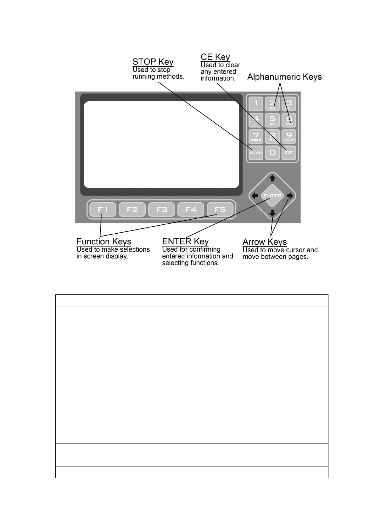
Figure 1. Front Panel Overview
Name
Function
Function Keys
(F1 to F5)
Use the function keys (F1 to F5) to activate the “button” displayed on
the screen above the key; for example, F1 for RUN.
Directional
Arrow Keys
The four Directional Arrow keys can move the cursor into different
directions.
ENTER key
The current selection is activated or accepted when the ENTER key is
pressed.
Alphanumeric
Keys (0~9)
The alphanumeric keys are usually used as number keys for the entry
of time, temperature, password and cycle numbers. When entering a
user name or protocol name, a small screen will pop out to display the
letters after pressing the Alphanumeric keys. Press the selected key
until the desired letter is highlighted. Press the ENTER key to select
the letter or wait 5 seconds.
CLEAR key
(CE)
Press CLEAR key will erase the entry in an input field.
STOP key
By pressing STOP, the Protocol current running will be terminated.
Page 8
4
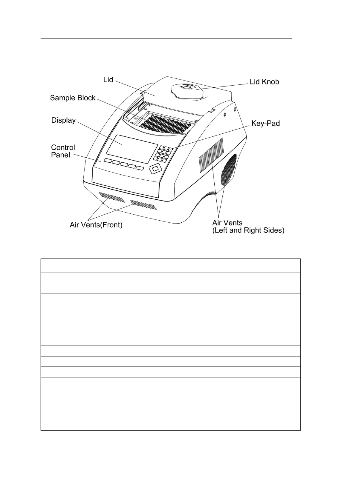
Figure 2. Front View
Name
Function
Lid
The lid with heating pad is designed to protect against evaporation
resulting from heating of the reaction tube and reaction plate.
Lid Knob
Rotate Lid Knob in clockwise will lower the heating plate to place
pressure on the cap of tubes. This forces the tubes to sit firmly in the
block for better contact. Rotate Lid Knob in counter-clockwise
direction until the Lid pops up. Only after the Lid pops, can users
slide the Lid to the rear.
Sample Block
Section of the unit in which sample tubes and plates are placed.
Key-Pad
Used to enter the various Protocols and settings.
Control Panel
which includes Display and Key-Pad
Display
Displays current status of the various system features and functions.
Air Vents (Front)
for air output
Air Vents (Left and
Right Sides)
for air output
Air Vents (Bottom)
for air intake
Page 9
Cleaver Scientific Thermal Cycler
5
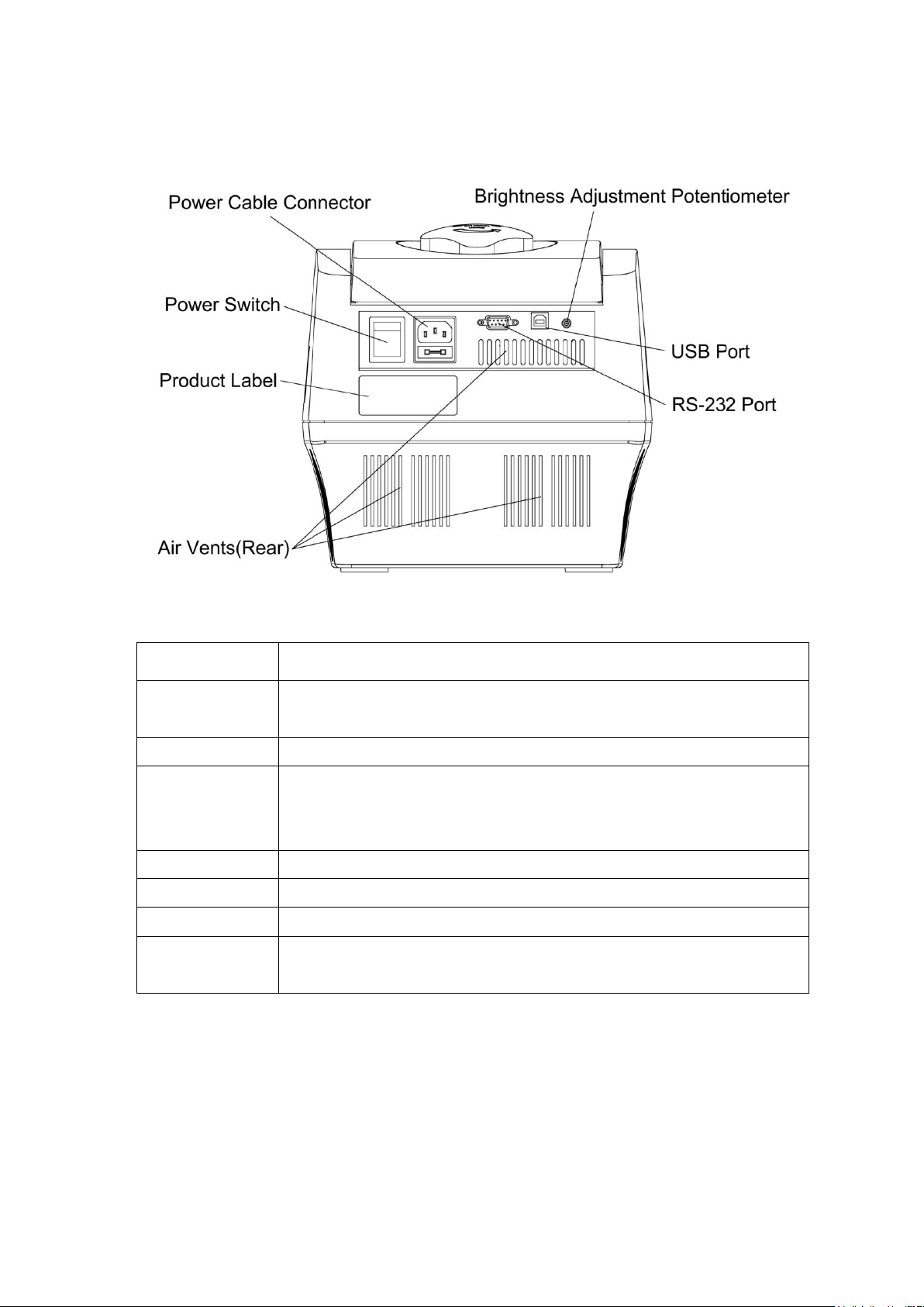
Figure 3. Rear View
Name
Function
Power Cable
Connector
Power cable socket and fuse.
Power Switch
Power On/Off switch
Brightness
Adjustment
Potentiometer
Control the brightness of LCD panel. Please use Philip-head screw
driver to adjust it.
USB Port
For run summary download to computer
RS-232 Port
For run summary download to computer
Air Vents(Rear)
For air output
Product Label
Indicate the model name, serial number, power specification, and
other important information
Page 10

6
Getting Started
3.1 Unpacking
Open the GTS96 thermal cycler package and confirm that all items below are included:
If there are any items missing, damaged, or incorrect items, please contact your
distributor or sales representatives immediately.
Note: Please use 7A fuse in power source 100~120/50~60Hz countries, while 3.15A fuse
is for power source 200~220V/50~60Hz countries.
3.2 Initial Operation
Place the machine on a steady, flat table. Please keep the machine at least 30cm from the
wall or other machine. Connect the power cord to the power socket in the rear of the
machine. Check the power source is compatible with your machine’s fuse rating input.
Press Power On/Off Button to switch on the machine. The screen will show the software
version for 10 seconds and then enter User Folder screen. Pressing any key will go to
User Folder screen immediately.
3.3 Heated Lid
The Heated Lid heats the air in the upper part of the sample vessels at higher temperature
than the reaction mixture. This prevents condensation of the evaporated water vapor on
the vessel walls, keeping the concentration unchanged during the heating and cooling
cycles. The top also places pressure on the caps of tubes and film on titer plates to prevent
vapor loss and cross contamination of samples.
When using full skirted plates it is highly recommended to use a Silicone Compression
Mat (to assist in placing even pressure on the plates.
Note:
1. If GTS96 is started cold, approximately two to three minutes will be required before
heated lid is at operating temperature.
2. To avoid heat dissipation, the Heated Lid should be closed and tighten during a
⚫ GTS96 thermal cycler unit
⚫ Operation manual
⚫ Electric fuses (7A & 3.15A)
⚫ AC power cord
⚫ Warranty card
Page 11
Cleaver Scientific Thermal Cycler
7
protocol run. Keeping the heated lid open during a protocol run might cause
“HEATER ERROR”, because the heated lid fails to reach the set temperature.
3. To evaporate the condensation water inside sample block, and to avoid “HEATER
ERROR”, users should turn off the Lid Temperature under SYSTEM mode before
heating the sample block and keeping the lid open.
3.4 Lid Opening/Closing
There are two ways to open the lid: 1) Slide the lid to the rear, 2) lift up the lid. The first
method is recommended for common operations and to prevent the skin burn from the
heated lid. The second method is used to clean up the heating plate of the lid.
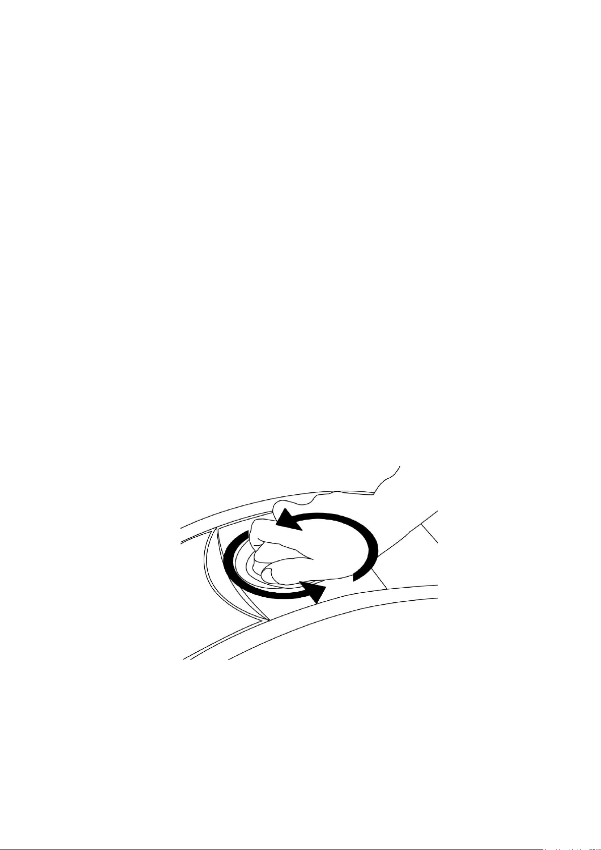
Rotate Lid Knob in a clockwise direction to lower down the heating plate and press down
on the cap of tubes, tighten until you feel resistance. This adjustment will provide better
contact between the tube or plates and the block for better performance. Rotate the Lid
Knob in counter-clockwise direction as shown in Figure 4 until the Lid pops out. Only
when the Lid pops out, users can slide the Lid to the rear as shown in Figure 5.
To lift up the lid for heating plate cleaning, please refer Figure 6 ~ 8.
Figure 4. Rotate Lid Knob to open the lid
Page 12
8
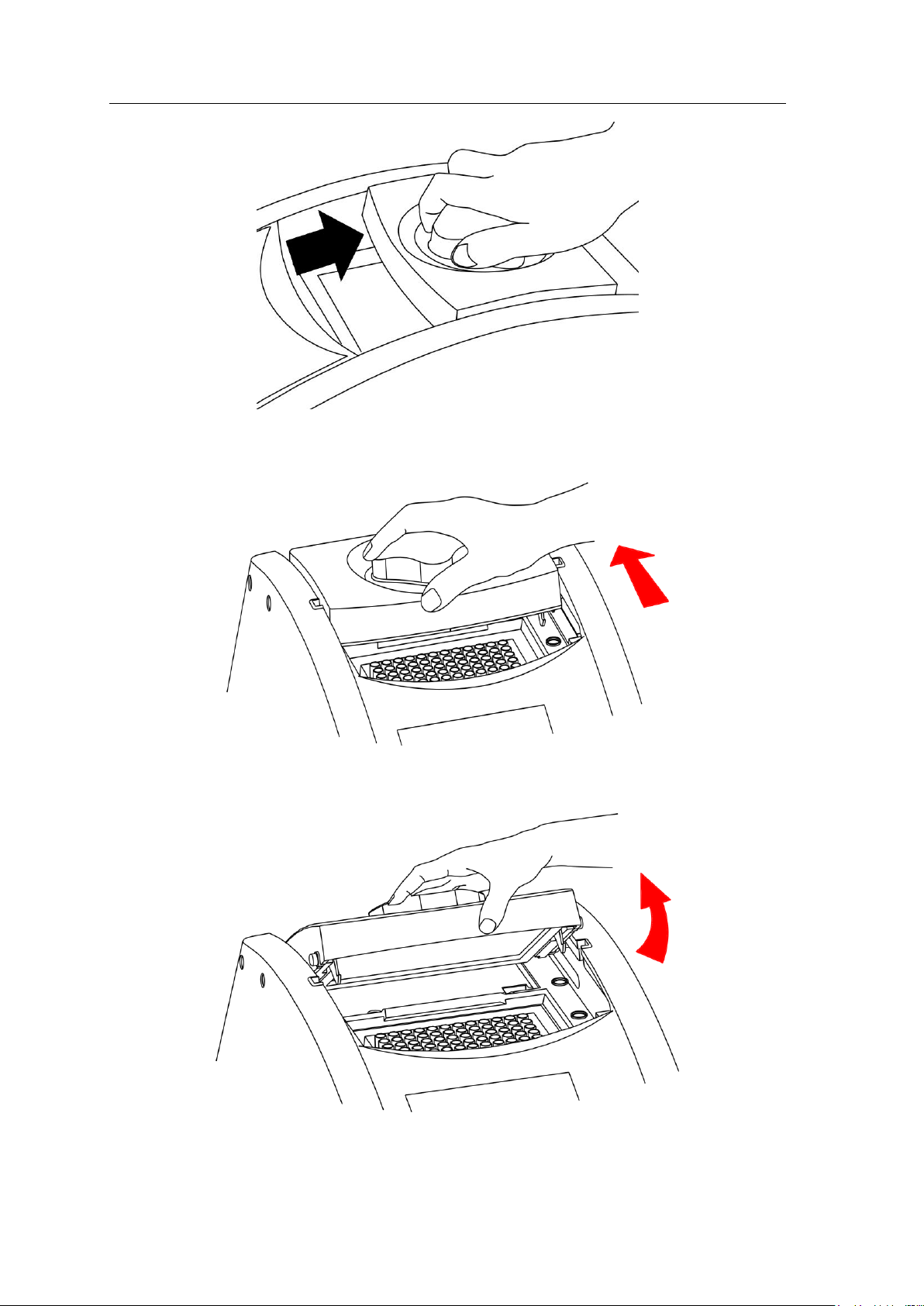
Figure 5. Slide the lid backward to access the block
Figure 6. Slide the lid to align the lid hinge with notches of top case
Figure 7. Lift the lid
Page 13

Cleaver Scientific Thermal Cycler
9
Figure 8. Rest the lid in vertical position
Page 14

10
3.5 Function Map
The User Screen includes 5 function options; 1) VIEW folders under selected User folder,
2) NEW(Create) a User, 3)EDIT a User, 4)DELETE a User, 5)SYSTEM. Once a user
folder is selected and the password is approved, users can; 1) RUN a Protocol,
2)NEW(Create) a protocol, 3) EDIT(VIEW) a Protocol, and 4) DELETE a Protocol.
The function map is shown in Figure 9. Various functions, including Gradient, can be
added to the selected/created Protocol.
Figure 9. Operation Flowchart
RUN
Protocol
NEW
Protocol
EDIT
(VIEW)
Protocol
DELETE
Protocol
EDIT
User
DELETE
User
SYSTEM
OPEN
User
User Folder
NEW
User
Insert
Delete
Advanced
Optimization
Increment
Pause
Data Log
Date &Time
Lid Temp.
Beeper
Administrator
Service Mode
Ramping Speed
Tm Calculator
Save
Main Menu
Page 15

Cleaver Scientific Thermal Cycler
11
3.6 Key Entry System
Note that the alphanumeric keys are assigned multiple characters, selectable by repeatedly
pressing the key to cycle through the available characters. The highlighted character or
number will automatically be entered into the name of a newly created or edited Protocol
(or User) after a very short period of time, if users don’t continue to press the key.
Key No.
Key Representation
0
0, space, +, =, <, >, &, (, ), %
1
1, . , , ,-, ?, ‘, #, : , ; ,/
2
A, B, C, a, b, c, 2
3
D, E, F, d, e, f, 3
4
G, H, I, g, h, i, 4
5
J, K, L, j, k, l, 5
6
M, N, O, m, n, o, 6
7
P, Q, R, S, p, q, r, s, 7
8
T, U, V, t, u, v, 8
9
W, X, Y, Z, w, x, y, z, 9
3.7 Loading the Reaction Vessel
For the optimal performance of the GTS96, we recommend Cleaver tubes and plates.
The recommended sample volume for 0.2 ml tubes or 96-well plates is 5-100ul. If using
the heated lid with full skirted 96 well plates it is highly recommended to use a Silicone
Compression Mat to assist in placing even pressure on the plates.
Note: To avoid deformation of the sample tubes or Strips, it’s important to load at least
one tube in each of the four corners and at least four tubes in the center of the block, this
will distribute the pressure evenly throughout the surface.
Page 16

12
User Folder Management
After the unit is turned on, the initial screen which contains software version and
manufacturer’s name will show up for 10 seconds and then enter User Folder screen.
Pressing any key will go to User Folder screen immediately.
A sample screen is shown below.
Users can use the function keys(F1~F4) above to view, create, edit and delete the User
folders. F5:SYSTEM is used for system settings.
Note:
1. The [ PRESET ] and [ PUBLIC ] folders are pre-registered folders which require no
Personal Identification Number(PIN) to enter.
2. The [ PRESET ] folder includes some frequently-used Protocols defined by vendor,
while the [ PUBLIC ] folder is open to all users.
4.1 Viewing a User Folder
All Protocols are stored inside the User folders. Use directional arrow keys to select a
User folder. Press F1:OPEN to view the names of all Protocols inside the selected folder.
To view the contents of the User, will require you to enter the 4-digit Personal
F 1
F 2
F 3
F 4
F 5
OOPPEENN
NNEEWW
EEDDIITT
UUSSEERR FFOOLLDDEERRSS 88//2211//22001111 1111::0000
PPRREESSEETT
PPUUBBLLIICC
LLaabb
MMiikkee
SSuussaann
JJeeffff
SSeelleecctt aa uusseerr ffoollddeerr
SSYYSSTTEEMM
DDEELLEETTEE
Directory
User Folder Name
Status Bar
Date & Time
Page 17

Cleaver Scientific Thermal Cycler
13
Identification Number(PIN) as shown in the screen below. After the PIN is entered,
press F1:ACCEPT or ENTER key to confirm the PIN. To run a Protocol, please refer
Section 5.1.
4.2 Creating a New User Folder
Under User Folder screen, press F2:NEW can create a new User folder. After entering the
new User name, press F1:ACCEPT to accept the new User folder name. The GTS96 will
prompt you to enter a 4 digit PIN. Pressing F1:ACCEPT will save the new folder name
and PIN.
Max. User folder name: 12 characters
Max. User folder no.: 50
4.3 Editing a User Folder
Under the User Folder screen, use directional arrow keys to select a User folder. Press
F3:EDIT to edit the User name. A PIN is required to edit the User folder name. After
editing the User folder name, press F1:ACCEPT to save the edited User name.
4.4 Deleting a User Folder
Use directional arrow keys to select a User folder. Press F4:DELETE to delete the
AACCCCEEPPTT
UUSSEERR FFOOLLDDEERRSS>>MMiikkee 88//2211//22001111 1111::0000
EEnntteerr PPIINN aanndd pprreessss AACCCCEEPPTT,, PPrreessss AACCCCEEPPTT iiff nnoott
PPIINN pprrootteecctteedd.
.
EEXXIITT
PPlleeaassee eenntteerr PPIINN::
F 1
F 2
F 3
F 4
F 5
Page 18

14
selected User folder. You are required to enter the PIN and press F1:ACCEPT or
ENTER . The screen will prompt “Do you want to delete”. Press F1:ACCEPT to
confirm the deletion. Press F5:EXIT to abort the deletion.
Note: User folders which contain any protocols can’t be deleted except by administrator.
Page 19

Cleaver Scientific Thermal Cycler
15
Protocol Management
After entering the selected User Folder, users can press F1~F4 keys to Run,
New(Create), Edit(View) and Delete a selected Protocol as shown below.
5.1 Running a Protocol
1. Press F1:RUN to run the selected Protocol under the User folder screen. The screen
will show as below.
MMiikkee>>PPRROOTTOOCCOOLL 88//2211//22001111 1111::0000
PPlleeaassee sseelleecctt aa pprroottooccooll aanndd pprreessss EENNTTEERR
TToouucchhddoowwnn 0077//2255//1111 0099::1100::2200
PPRROOTTOOCCOOLL DDAATTEE TTIIMMEE
LLaabb 0077//2288//1111 0033::2255::3300
RRUUNN
NNEEWW
EEDDIITT
EEXXIITT
DDEELLEETTEE
F 1
F 2
F 3
F 4
F 5
SSTTAARRTT
MMiikkee>>LLaabb>>RRUUNN 88//2211//22001111 1111::0000
MMooddee::11((11--22)) VVoolluummee:: 5500uull((55--110000uull))
11::TTuubbee CCoonnttrrooll 22::BBlloocckk CCoonnttrrooll
EEXXIITT
9944..00 9944..00 5555..00 7722..00 7722..0000 44..0000
55::0000 00::3300 00::3300 00::3300 1100::0000
TTeemmpp
TTiimme
e
11 TTmmpp 33 TTmmpp 2255 CCyycc 22 TTmmpp 11 CCyycc
F 1
F 2
F 3
F 4
F 5
Page 20

16
2. Users are required to select a Temperature Control Mode before running the Protocol.
Mode 1(Tube Control): Enable system operation with simulated temperature
control. If Mode 1 is selected, users are required to input the sample volume :
5-100ul. In this mode, temperature control is based on Block temperature and
an algorithm which estimates sample temperature based on the block
temperature and the sample volume. Recommended for more accurate
temperature control.
Mode 2(Block Control): Enable system operation with maximum temperature
control based on the actual block temperature. Recommended for normal
operation.
3. Press F1:START to run the Protocol.
Note:
1. The highlighted temperature (Temp) value represents the current block temperature
during Protocol running. The highlighted time (Time) value below represents the
remaining running time in the temperature segment. Once the countdown is completed,
the highlighted section will continue to move to the next temperature or cycle segment
and start counting down the time.
2. The Lid temperature will flash on the status bar when the Protocol starts and remain
on until it reaches 50ºC. When the lid reaches 50°C “HOT!” will appear in the right
hand corner and remain until the temperature falls below 40°C The sample block will
start to heat up when the lid temperature reaches its set temperature.
5.2 Pause a Protocol
During running of the Protocol, press F1:PAUSE will pause the running Protocol for 10
minutes. The Protocol will continue after the Pause stops. The Protocol won’t be paused
until set temperature is achieved. To resume running the Protocol, press F1:RESUME.
5.3 Viewing Running Protocol Information
Press F2:INFO to view the Protocol information screen as shown below during operation.
Press F5:RETURN to return the running Protocol screen. The Protocol information
screen will return to the running Protocol screen in 3 minutes, if F5:RETURN is not
pressed.
Page 21

Cleaver Scientific Thermal Cycler
17
5.4 Terminating a Protocol
1. Press F5:EXIT or STOP key in the bottom-left side of the Alphanumeric keypad to
terminate a running protocol.
2. The display will show message “Do you want to abort?” as below.
3. Press F1:YES or STOP key again to terminate the Protocol. Press F5:NO to return to
the running Protocol.
4. The display screen will return to Protocol screen.
LLaabb>>RRUUNN>>SSTTAARRTT 88//2211//22001111 1133::0000
MMooddee::11((11--22)) VVoolluummee:: 5500uull((55--110000uull))
RREETTUURRNN
94.0 94.0 55.0 72.0 72.00 4.00
55::0000 00::3300 00::3300 00::3300 1100::0000
TTeemmpp
TTiimme
e
11 TTmmpp 33 TTmmpp 2255 CCyycc 22 TTmmpp 11 CCyycc
RRuunn ssttaarrtteedd:: 0088//2211//1111 1122::2200::5500
RRuunn wwiillll eenndd:: 0088//2211//1111 1133::5500::2200
F 1
F 2
F 3
F 4
F 5
YYEESS
MMiikkee>>LLaabb>>RRUUNN>>SSTTAARRTT 88//2211//22001111 1111::0000
EEssttiimmaatteedd RReemmaaiinniinngg:: 0011::2200
NNOO
9944..00 9944..00 5555..00 7722..00 7722..0000 44..0000
55::0000 00::3300 00::3300 00::3300 1100::0000
TTeemmpp
TTiimme
e
11 TTmmpp 33 TTmmpp 2255 CCyycc 22 TTmmpp 11 CCyycc
DDoo yyoouu wwaanntt ttoo aabboorrtt??
F 1
F 2
F 3
F 4
F 5
Page 22

18
Creating a New Protocol
A new Protocol can be created by going to the User Folder and selecting and editing a
basic Protocol format, and then assigning it a new name.
1. Select User name on User screen. Press F1:OPEN or ENTER button to enter User
Folder.
2. Key in PIN to enter the User’s folder.
3. Press F2:NEW to create a new Protocol by using a standard template, shown below.
Note: Users can create a new Protocol under Public folder without a PIN. Users can edit
a new Protocol inside Preset folder, BUT can not save these changes to the original
protocol settings.
6.1 Changing Temperature/Time Values
1. Press directional arrow keys to move cursor to the temperature or time settings
required to be changed.
2. Enter your desired values and press ENTER or to move cursor to other values to save
the settings.
MMiikkee>>PPRROOTTOOCCOOLL>>NNEEWW 88//2211//22001111 1111::0000
9944..00 9944..00 5555..00 7722..00 7722..0000 44..0000
55::0000 00::3300 00::3300 00::3300 1100::0000
TTeemmpp
TTiimme
e
11 TTmmpp 33 TTmmpp 2255 CCyycc 22 TTmmpp 11 CCyycc
SSAAVVEE
EEXXIITT
IINNSSEERRTT
DDEELLEETTEE
AADDVV..
3 Tmp. Segments
1 Tmp. Segment
Tmp./ Time Values
F 1
F 2
F 3
F 4
F 5
Page 23

Cleaver Scientific Thermal Cycler
19
The temperature and time ranges are shown below.
Temperature range: 4.0 to 99.9
◦
◦
C
Time range (minute: second): 00:01 to 99:59 ( 99:99 = ∞ )
6.2 Inserting/Deleting Temperature Segment
Temperature Segment can be inserted or deleted by selecting F2:INSERT or
F3:DELETE key. The inserted or deleted temperature segment is dependent upon the
location on the temperature segment where the cursor is positioned. If the cursor is
positioned inside the first multi-temperature/time segment, pressing F2/F3 will
insert/delete the whole Multi-Temperature Cycle. If the cursor is located in any other
Multi-Temperature/Time segment only the selected segment will be inserted/deleted.
6.3 Changing Temperature Segment Count (Temp)
and Cycle Count (Cyc)
The Temperature Segment Count(Temp) can be modified by entering a new value (1 to 20)
in the first Temperature position and pressing ENTER. When the Temperature Segment
Count is larger than one, the temperature Cycle Count (Cyc) will appear. The
Multi-Temperature Segment will cycle during this segment. The maximum temperature
segment per protocol is 12 segments. The temperature segment count and cycle count
ranges are shown below.
Temperature Segment Count(Temp.) range: 1 to 20
Cycle Count(Cyc) range: 1 to 99
6.4 Advanced Settings
Users can set up the following advanced functions: 1) Optimization, 2)
Temperature/Time Increment/Decrement, 3) Pause,.
F4:ADVANCE button, is used to enter these settings. The screen below will be
displayed.
Page 24

20
6.4.1 Optimization Temperature Setting
1. To enter an Optimization Temperature setting, place your cursor on the desired
Temperature Segment. Select F2:OPTI. to enter the screen below.
2. The temperatures of all BLOCK offset are based on BLOCK#1. If press F2:AUTO
to set gradient temperature, each BLOCK will add 4◦C automatically based on the
preceding BLOCK. Prior to press F3:AVG. users need to enter BLOCK#6 setting,
and the screen will show the calculated temperature gradient from BLOCK#1 to
BLOCK#6 as show in Figure 10. This reflects the variation of the temperature from
the BLOCK#1 (coolest) to the BLOCK#6 (hottest).
3. There are specially function in the optimization temperature setting. All temperatures
are based on BLOCK#1 and users can move the cursor to press any higher
temperature (Range:0.1~24.0◦C) on BLOCK#2 to BLOCK#6.
4. Press F5:EXIT to confirm the settings. Press F1:OFF to re-enter the settings. A
capital letter and High-temperature value; “G70.0”, will appear on the Temperature
Segment graph and Low-temperature value will be shown on the Temp value of the
section.
To remove the Optimization Temperature setting, place your cursor in the same
temperature segment with “G ” Gradient Temperature symbol. Press F2:OPTI. again.
The screen will show each BLOCK temperature settings. Press F1:OFF to clear the
Optimization Temperature setting. Press F5:EXIT will delete the Gradient Temperature
setting and its symbol.
MMiikkee>>PPRROOTTOOCCOOLL>>NNEEWW>>AADDVV.. 88//2211//22001111 1111::0000
9944..00 9944..00 5555..00 7722..00 7722..00 44..00
55::0000 00::3300 00::3300 00::3300 1100::0000
TTeemmpp
TTiimme
e
11 TTmmpp 33 TTmmpp 2255 CCyycc 22 TTmmpp
EEnntteerr ddeessiirreedd tteemmpp,, ttiimmee oorr nnuummbbeerr..
F 1
F 2
F 3
F 4
F 5
EEXXIITT
OOPPTTII..
IINNCCRREE..
PPAAUUSSEE
Page 25

Cleaver Scientific Thermal Cycler
21
Figure 10. Block layout of 96-well model
The Optimization temperature ranges are shown below.
Temperature setting range: 30.0 to 99.0 ◦C
Temperature difference: 0.1 to 24.0 ◦C
MMiikkee>>PPRROOTTOOCCOOLL>>NNEEWW>>OOPPTTII.. 88//2211//22001111 1111::0000
BBlloocckk
TTeemmpp.
.
EEXXIITT
AAUUTTOO
BBlloocckk
TTeemmpp.
.
##11
50.0
AAllll OOffffsseett iiss bbaassee oonn BBLLOOCCKK ##11
##22
54.0
##33
58.0
##44
62.0
##55
66.0
##66
70.0
OOFFFF
AAVVGG..
F 1
F 2
F 3
F 4
F 5
BLOCK#1 BLOCK#2 BLOCK#3
BLOCK#4 BLOCK#5 BLOCK#6
Page 26

22
6.4.2 Incremental/Decremental Temperature and Time
Settings
To increase or decrease the dwell time or temperature after each repeat you must have
more than one cycle repeat. i.e. 55ºC and a dwell time 40 seconds, you could decrement
the second step by 5 seconds the second step would be 55ºC and a dwell time of 35
seconds.
1. Place the cursor at the Temperature or Time values. Press F3:INCRE.
2. To select increment/decremental values. The screen will ask to input the increment
values. Press F3: + or F4: - to choose increment or decrement.
3. Enter your desired values and press ENTER. The graph will show the
increment/decrement values.
4. Press F1:ACCEPT to accept the values or F2:CLEAR to re-enter the values.
To remove the Incremental/Decremental Temperature and Time settings, place the cursor
in the temperature segment with “Incremental/Decremental Temperature and Time
values”. Select F2:CLEAR to clear the values. Select F1:ACCEPT will remove the
incremental/ Decremental Temperature setting and its symbol.
Temperature Increment
Max. Temperature incremental value: +/- 9.9 ◦C
Max. Time incremental value (minute:second): +/- 9:59
BBBBBB>>PPRROOTTOOCCOOLL>>NNEEWW>>IINNCCRREE.. 88//2211//22001111 1133::0000
9944..00 9944..00 5555..00 7722..00 7722..00 44..00
55::0000 00::3300 00::3300 00::3300 1100::0000
TTeemmpp
TTiimme
e
11 TTmmpp 33 TTmmpp 2255 CCyycc 22 TTmmpp
EEXXIITT
CCLLEEAARR
++ --
TTeemmppeerraattuurree IInnccrreemmeenntt::
++ 00..0
0
F 1
F 2
F 3
F 4
F 5
Page 27

Cleaver Scientific Thermal Cycler
23
Note:
1. Temperature limits 4.0ºC to 99.9ºC. DO NOT exceed.
2. Only Multi-cycle segments will have incremental/ decremental time or temperature
function.
Time Increment
6.4.3 Pause Setting
Position your cursor on desired temperature segment. Press F4:PAUSE to add a pause
action during operation. The “Pause” will appear on the Temperature Segment graph.
The pause will last for 10 minutes, then the Protocol will resume the operation.
To remove the Pause setting, place the cursor under “P.” Pause symbol. Press F4:PAUSE
again will remove the Pause setting and its symbol.
6.5 Saving a Protocol
After all settings are entered, press F1:SAVE will store the protocol. Screen will
Prompt “Please enter protocol name” A Protocol name is required to be entered.
Max. Protocol name: 12 characters
BBBBBB>>NNEEWW>>IINNCCRREE.. 88//2211//22001111 1133::0000
9944..00 9944..00 5555..00 7722..00 7722..00 44..00
55::0000 00::3300 00::3300 00::3300 1100::0000
TTeemmpp
TTiimme
e
11 TTmmpp 33 TTmmpp 2255 CCyycc 22 TTmmpp
EEXXIITT
CCLLEEAARR
++
--
TTiimmee IInnccrreemmeenntt:: ++
00::000
0
F 1
F 2
F 3
F 4
F 5
Page 28

24
Editing (Viewing) a Protocol
An editing Protocol can be saved under a new name (newly created Protocol) or under the
same name (edited Protocol).
Under the User’s Folder, choose the Protocol to be edited. Select F3:EDIT to edit the
selected Protocol. This displays the existing Protocol and enables editing of the
temperature segment and numerical values as shown below.
Please refer Chapter 6 Creating a New Protocol to edit the temperature segment and
numerical values, and other advanced functions. Press F1:SAVE to save the edited
Protocol under the original name or F2:SAVE A to as a new protocol.
Deleting a Protocol
1. An existing Protocol can be deleted under a User’s Folder.
2. Under the User’s Folder screen, choose a Protocol. Select F4:DELETE to delete the
selected Protocol.
3. If F4:DELETE is selected the screen will prompt you “Are you sure you want to
delete?” Press F1:YES to confirm the deletion. Press F5:NO to abort the deletion.
SSAAVVEE
AA>>MMiikkee>>EEDDIITT 88//2211//22001111 1111::0000
MMaaxxiimmuumm:: 1122 cchhaarraacctteerrss
EEXXIITT
PPrrooggrraamm nnaammee::AA
SSAAVVEEAASS
CCLLEEAARR
KKeeyy00((00++==<<>>&&(())%%))
KKeeyy11((11..,,--??’’##::;;//))
F 1
F 2
F 3
F 4
F 5
Page 29

Cleaver Scientific Thermal Cycler
25
Note: Protocols in the Preset Protocols Folder can’t be deleted, while Protocols in the
Public Folder can be deleted by any user if not password protected.
System Setup
System Setup contains 6 functions:
1. Data Log: contains the history of the latest-run Protocol.
2. Date & Time: Users can change the Date and Time settings.
3. Lid Temperature: Users can choose the preferred lid temperature as default setting
during running a Protocol.
4. Beeper: Users can turn on/off the audible beep.
5. Administrator: Users can delete unwanted Usernames and their Protocols.
6. Service Mode: is reserved for Service engineers.
7. Ramping Speed: Users can choose the High Ramping Speed or Low Ramping
Speed.
8. Tm Calculator: Press A, T, C, and G number of sequence, then users can get the
Tm value.
MMIIKKEE>>PPRROOTTOOCCOOLL 88//2211//22001111 1111::0000
AArree yyoouu ssuurree yyoouu wwaanntt ttoo ddeelleettee??
TToouucchhddoowwnn 0077//2255//1111 0099::1100::2200
PPRROOTTOOCCOOLL DDAATTEE TTIIMMEE
LLaabb 0077//2288//1111 0033::2255::3300
YYEESS
NNOO
F 1
F 2
F 3
F 4
F 5
Page 30

26
9.1 Data Log
The Data Log records a log of activity for the most recently run Protocol. Executing a
new Protocol updates the history log by overwriting previous log. To export log to a PC a
Hyper Terminal communication protocol must be installed. Hyper Terminal
communication protocol comes free with Windows.
Please refer Appendix D: Hyper Terminal and USB Driver Setup.
SSYYSSTTEEMM>>DDaattaa LLoogg 88//2211//22001111 1111::0000
FFOOLLDDEERR:: MMiikkee
PPRROOTTOOCCOOLL:: LLaabb
TTuubbee CCoonnttrrooll,, VVoolluummee:: 5500 uull
PPrroottooccooll ccoommpplleetteedd ssuucccceessssffuullllyy..
RRuunn :: 1133::2200::1100 ttoo 1144::2255::0000
EExxiitt
PPCC
F 1
F 2
F 3
F 4
F 5
F 1
F 2
F 3
F 4
F 5
SSEELLEECCTT
SSYYSSTTEEMM 88//2211//22001111 1111::0000
DDaattaa LLoogg
DDaattee&&TTiimmee
LLiidd TTeemmppeerraattuurree
BBeeeeppeerr
AAddmmiinniissttrraattoorr
SSeerrvviiccee MMooddee
RRaammppiinngg SSppeeeedd
TTmm CCaallccuullaattoorr
PPrreessss EEnntteerr oorr FF11 ttoo sseelleecctt yyoouurr SSyysstteemm..
EEXXIITT
Page 31

Cleaver Scientific Thermal Cycler
27
9.2 Date & Time
Users can change the date type, default date and time of this unit by selecting Date
&Time screen as shown below under SYSTEM screen. Please remember to press
F1:ACCEPT to store your settings.
9.3 Lid Temperature
Users can change the temperature of lid of this unit by selecting Lid Temperature screen
as shown below under SYSTEM screen. Please remember to press F1:ACCEPT to store
your settings. Two temperature segments: 60~65 ◦C and 100~115 ◦C are available.
AACCCCEEPPTT
SSYYSSTTEEMM>>DDAATTEE&&TTIIMMEE 88//2211//22001111 1111::0000
DDaattaa TTYYPPEE:: 22
((11.. YY//MM//DD 22..MM//DD//YY 33..DD//MM//YY))
DDeeffaauulltt DDaattee :: 0088//2211//1111
DDeeffaauulltt TTiimmee :: 1111::0000::3333
PPrreessss FF11 ttoo ssaavvee yyoouurr sseettttiinnggss
EEXXIITT
F 1
F 2
F 3
F 4
F 5
AACCCCEEPPTT
SSYYSSTTEEMM>>LLIIDD TTEEMMPPEERRAATTUURREE 88//2211//22001111 1111::0000
LLiidd TTeemmppeerraattuurree FFuunnccttiioonn:: 11
((11::OONN 22::OOFFFF))
LLiidd TTeemmppeerraattuurree:: 110055
◦
◦
CC
((6600----6655 )),,((110000----111155)
)
◦
◦
CC
PPrreessss FF11 ttoo ssaavvee yyoouurr sseettttiinnggss
EEXXIITT
F 1
F 2
F 3
F 4
F 5
Page 32

28
9.4 Beeper
Users can turn ON or OFF the sound of this unit by selecting the Beeper screen as shown
below under SYSTEM screen. Please remember to press F1:ACCEPT to store your
settings.
9.5 Administrator
The password of Administrator is “9610”. The Administrator of this unit has rights to
delete any User Folder and any Protocols inside a User’s Folder.
9.6 Service Mode
Only authorized service personnel have the password to enter Service Mode and perform
necessary maintenance and repairs.
9.7 Ramping Speed
Users can choose the Ramping Speed. High Ramping Speed heating rate about 4◦C/sec
and cooling rate about 3◦C/sec. Low Ramping Speed heating rate about 3◦C/sec and
cooling rate about 2◦C/sec. Please remember to press F1:SAVE to store your settings.
AACCCCEEPPTT
SSYYSSTTEEMM>>BBEEEEPPEERR 88//2211//22001111 1111::0000
BBeeeeppeerr FFuunnccttiioonn:: 22
((11::OONN 22::OOFFFF))
PPrreessss FF11 ttoo ssaavvee yyoouurr sseettttiinnggss
EEXXIITT
F 1
F 2
F 3
F 4
F 5
Page 33

Cleaver Scientific Thermal Cycler
29
9.8 Tm Calculator
Users can press the number of the bases of A, T, C and G in the sequence, then press
F1:RUN to get the Tm value of the sequence.
SSAAVVEE
SSYYSSTTEEMM>>RRAAMMPPIINNGG SSPPEEEEDD 88//2211//22001111 1111::0000
RRaammppiinngg SSppeeeedd:: 11
11 :: HHiigghh RRaammppiinngg SSppeeeedd
22 :: LLooww RRaammppiinngg SSppeeeedd
PPrreessss FF11 ttoo ssaavvee yyoouurr sseettttiinnggss
EEXXIITT
F 1
F 2
F 3
F 4
F 5
RRUUNN
SSYYSSTTEEMM>>TTMM CCAALLCCUULLAATTOORR 88//2211//22001111 1111::0000
AA == 00
TT == 00
CC == 00
GG == 00
PPrreessss FF11 ttoo CCaallccuullaattee
EEXXIITT
F 1
F 2
F 3
F 4
F 5
Page 34

30
Maintenance and Troubleshooting
10.1 Cleaning the unit
Please ensure that no liquid is spilled onto or into the unit. In addition, periodically wipe
it clean of dust and other residue that comes with normal operation of the unit. Use a soft,
lint-free cloth and deionized water. Air vents should be vacuumed to remove dust.
10.2 Cleaning the heated lid
Make sure the GTS96 is unplugged and cooled down. To clean the heated slide the lid
back on the tracks until the front black pins align with the two slots, taking care that the
rolleiflex cable is clear. Lift the lid from the front, (be careful of sharp edges) and flip up.
Use mild detergents to clean material from the lid. A Kimwipe™ dipped in 70% ethanol
will help remove and residue from sealing tape. Make sure the lid is dry prior to
lowering it into the tracks. Once the lid in secure in the tracks make sure the lid easily
slides forward.
10.3 Replacing a Fuse
The fuse is located in the power socket module, just below the power connector. If the
unit does not turn on when the power switch is turned on, then replace the fuse.
To replace the fuse:
1. Disconnect the power cord from the unit.
2. Remove the fuse drawer with a small-blade screwdriver.
3. Pull the fuse out of the fuse socket and replace the fuses with one having the
correct current rating.
4. For 100V-120V operation: Use 7.0A, 5 x 20mm, Glass Tube.
5. For 220 V- 240 V operation: Use 3.15A, 5 x 20 mm, Glass Tube.
6. Reinsert fuse into the fuse socket. Reinsert the fuse drawer.
10.4 Changing the Thermal block
1. Slide the lid to the furthest point back.
2. Remove the two plastic plugs and two screws holding the face plate.
3. Flip the face plate forward to gain access to the block.
4. Remove the two set screws holding the heating block.
5. Gently slide the Thermal block forward, once clear of the frame remove it from
Page 35

Cleaver Scientific Thermal Cycler
31
the unit.
6. Slide the new block into place and connect the plug.
7. Gently slide the block until the two screw holes are lined up.
8. Replace the two screws and plugs.
9. Shut the face panel and secure it with two screws.
Troubleshooting
Problem
Cause
Action
The display is off even when
power is switched on.
1. Power is not reaching the
system.
2. Power cord is not
plugged into the socket
properly.
3. Power fuse is blown out.
4. Block fuse is blown out.
1. Check power source
voltage.
2. Reconnect the power
cord.
3. Replace the power fuse.
4. Return the unit for
service.
Can’t reach 4C.
1. Operating temperature
environment may be
unsuitable.
2. Electronic cooling
element may be damaged
or aged.
1. Operate the unit in a
environment temperature
between 15 to 30 C.
2. Return the unit for
service.
Cycle time is too long
1. Operating environment
temperature may be
unsuitable.
2. Electronic cooling
element may be damaged
or aged.
3. Faulty temp. sensor.
1. Operate the system in a
temperature environment
between 15 to 30 C.
2. Return the unit for
service.
3. Return the unit for
service.
Lid heater does not work.
1. Lid heater is set off.
2. Lid sensor problem
1. Check Lid Temperature
setting in System Mode.
2. Return the unit for
service.
No key entry sound.
1. Sound may currently be
set off.
2. Faulty keys or keypad
wiring.
1. Check Beeper setting in
System Mode.
2. Return the unit for
service.
The display goes off.
1. Faulty backlight.
1. Check the LCD contrast.
Page 36

32
2. Faulty LCD panel
2. Return the unit for
service.
Display is too dark or light
Backlight brightness is not
adjusted properly.
Adjust Display Brightness
Potentiometer.
Lid will not close.
1. Foreign matter, between
lid heater and sample
block.
2. Faulty lid lock
mechanism.
Remove the foreign object or
matter.
Error message appears.
Refer to list of error
messages below.
Check the nature of the error
and take the suggested
actions.
11.1 Error Messages
Message
Cause
Action
HEATER ERROR!
⚫ Lid temperature sensor problem.
⚫ Lid temperature exceeds 132 °C.
⚫ Lid temperature can’t reach the set
temperature.
Reboot the unit.
BLOCK ERROR!
⚫ Block temperature sensor or heating
element problems.
⚫ The unit can’t reach the set
temperature, because the room
temperature is too high.
⚫ The block temperature exceeds 108
°C.
Cool down the room
temperature. Reboot the unit.
ROOM ERROR!
⚫ Room temperature sensor problem.
Reboot the unit
ROOM > 30 °C
⚫ The room temperature exceeds 30
°C.
⚫ Two running units are too close to
each other.
Cool down the room
temperature. Reboot the unit.
Remove any objects
blocking the vents.
Keep two running units at
least 30cm from each other.
Page 37

Cleaver Scientific Thermal Cycler
33
Appendix A: Technical specifications
Model Name
TC9610/TC9610-230V
Sample Capacity
0.2ml x 96 tubes
Temperature Ranges
4 ~ 99.9 C
Temperature Accuracy
+/- 0.5C ( 30 to 99.9 C)
Temperature Uniformity
+/- 0.5C
Max. Temp. Increment/Decrement Rate
4C / 3 C
Gradient Temperature
30 ~ 99 C (Max. temp. difference: 24 C)
Max. Lid Temperature
60~65/ 100~115 C
Protocol Capacity
200 sets
Operating Temperature
15 ~ 30 C
Operating Humidity
20 ~ 80% RH
Networking
1 x RS-232, 1 x USB
Power Supply
100 to 240V AC, 50/60 Hz, 750VA
Dimensions (W x D x H)
24 x 25 x 42cm
Weight (Net)
9 Kg
Page 38

34
Appendix B: Protocols in Default Folder
⚫ 2-Step
⚫ Gradient
SSTTAARRTT
PPRREESSEETT>>22--SSTTEEPP>>RRUUNN 88//2211//22001111 1111::0000
MMooddee::11((11--22)) VVoolluummee:: 5500uull((55--110000uull))
11::TTuubbee CCoonnttrrooll 22::BBlloocckk CCoonnttrrooll
EEXXIITT
9944..00 9944..00 5555..00 5555..0000 44..0000
55::0000 00::3300 00::3300 1100::0000
TTeemmpp
TTiimme
e
11 TTmmpp 22 TTmmpp 2255 CCyycc 22 TTmmpp 11 CCyycc
F 1
F 2
F 3
F 4
F 5
PPRREESSEETT>>GGRRAADDIIEENNTT>>RRUUNN 88//2211//22001111 1111::0000
9944..00 9944..00 5555..00 7722..00 7722..00 44..00
55::0000 00::3300 00::3300 00::3300 1100::0000
TTeemmpp
TTiimme
e
11 TTmmpp 33 TTmmpp 2255 CCyycc 22 TTmmpp 11 CCyycc
SSTTAARRTT
EEXXIITT
G.
MMooddee::11((11--22)) VVoolluummee:: 5500uull((55--110000uull))
11::TTuubbee CCoonnttrrooll 22::BBlloocckk CCoonnttrrooll
F 1
F 2
F 3
F 4
F 5
Page 39

Cleaver Scientific Thermal Cycler
35
⚫ Touch down
⚫ Time Increment
PPRREESSEETT>>TToouucchh ddoo..>>RRUUNN 22001111//88//2211 1133::0000
9955..00 9955..00 6655..00 7722..00 7722..00 44..00
55::0000 00::3300 00::3300 00::3300 1100::0000
TTeemmpp
TTiimme
e
11 TTmmpp 33 TTmmpp 2200 CCyycc 22 TTmmpp
SSTTAARRTT
EEXXIITT
MMooddee::11((11--22)) VVoolluummee:: 5500uull((55--110000uull))
11::TTuubbee CCoonnttrrooll 22::BBlloocckk CCoonnttrrooll
-- 00..55
F 1
F 2
F 3
F 4
F 5
PPRREESSEETT>>TTiimmee iinncc..>>RRUUNN 22001111//88//2211 1133::0000
9955..00 9955..00 6655..00 7722..00 7722..00 44..00
55::0000 00::3300 00::3300 00::3300 1100::0000
TTeemmpp
TTiimme
e
11 TTmmpp 33 TTmmpp 2200 CCyycc 22 TTmmpp
SSTTAARRTT
EEXXIITT
MMooddee::11((11--22)) VVoolluummee:: 5500uull((55--110000uull))
11::TTuubbee CCoonnttrrooll 22::BBlloocckk CCoonnttrrooll
-- 00::0055
F 1
F 2
F 3
F 4
F 5
Page 40

36
Cleaver Scientific Ltd.
Unit 41
Somers Road Ind. Est.
Rugby
Warwickshire
CV22 7DH
Declaration of Conformity
Product Name: GTS96 Thermal Cycler
Model Names: TC9610 /TC9610-230
All models comply with the following European standards:
EMC: EN 61326 (Group 1, Class B)
Safety: EN 61010-1 and EN 61010-2-010
To the best of my knowledge and belief, these units conform to these
standards.
Name: Deb Cleaver
Position: Quality Assurance
Issue Date: 2016/08/04
Appendix C: CE Declaration
Page 41

Cleaver Scientific Thermal Cycler
37
Cleaver Scientific Ltd.
Unit 41 Somers Road Industrial Estate
Rugby
Warwickshire
CV22 7DH
 Loading...