

CleaverBrooks Q6-130, Q6-075, Q6-055, Q6-100, Q8-175 Installation Operation & Maintenance
...Page 1
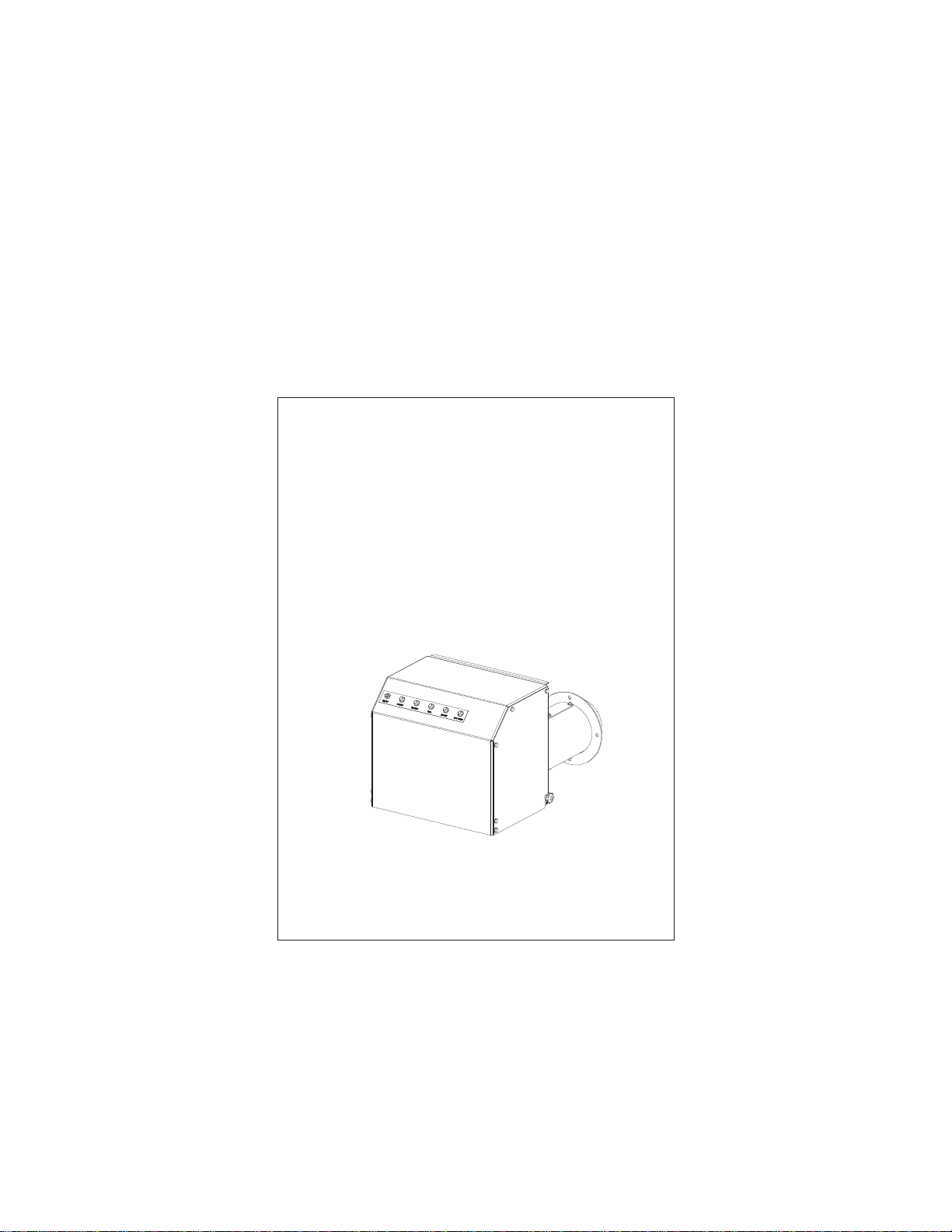
Table Of Contents
ProFire Q
Full Modulation Burner
with UV flame detection
Installation
Operation
Maintenance
Manual Part No. 750-437 07/2019
Page 2

Page 3
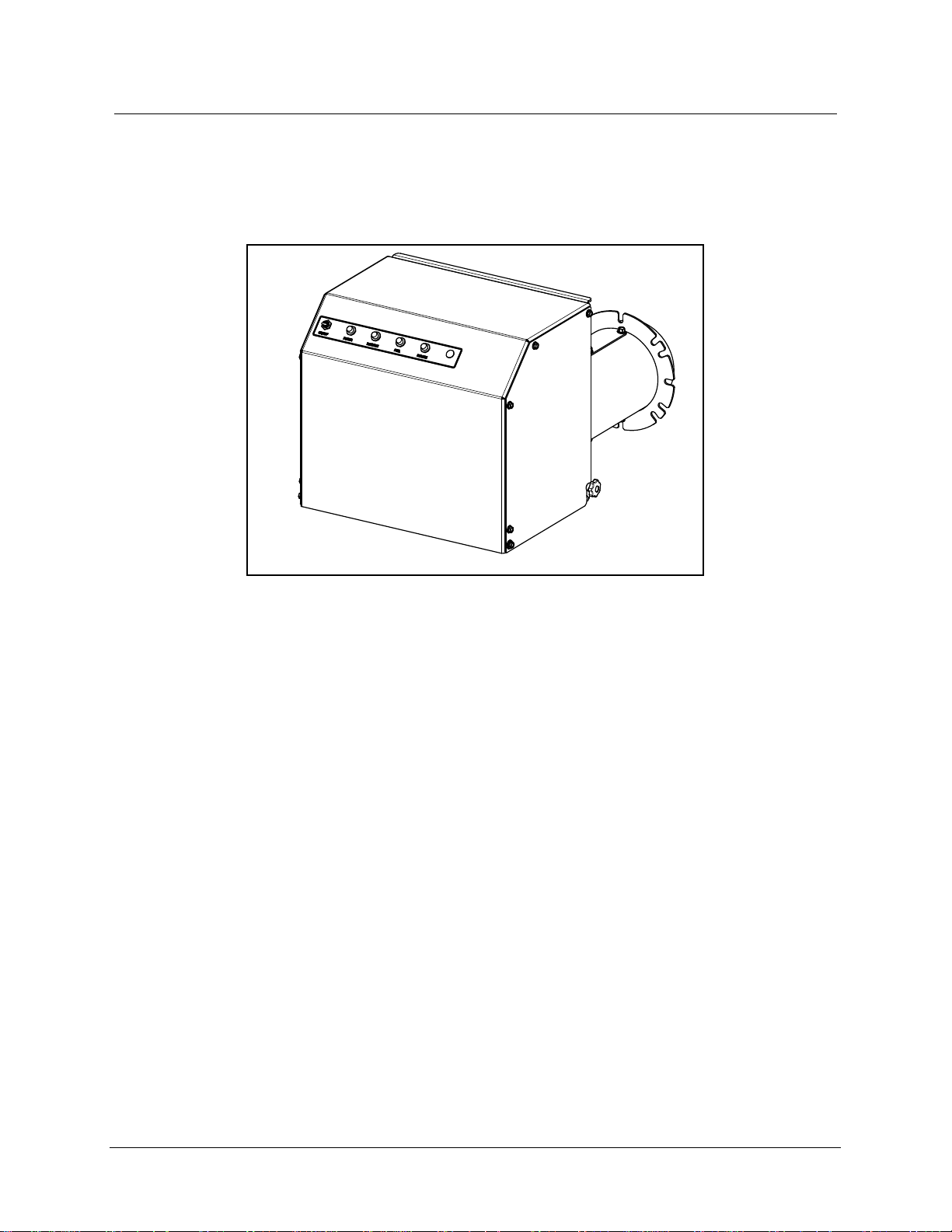
Q SERIES
Linkageless Full Modulation Burner with UV Flame Detection
750-00516-000
Manual Number: 750-00437
Revision 07/2019
Information to be filled out by owner
Unit Serial Number:
Date of Installation:
Distributor Information
Name:
Address:
Phone Number:
Copyright © 2019 by Cleaver-Brooks
All rights reserved. No part of this document may be reproduced, stored in a retrieval system, or transmitted in any form or by any means
without the prior written consent of Cleaver-Brooks.
Cleaver-Brooks
351 21st Street
Monroe, WI 53566
608-325-3141
cleaverbrooks.com
750-437
Q Series Full Modulation
i
Page 4

Q Series Installation, Operation, and Service Manual
Table of Contents
Preface iv
Specifications v
Dimensions vi
Spare Parts List vii
CHAPTER 1 Introduction 1-1
Description 1-1
Control Panel 1-2
Burner Control and Air Delivery 1-3
Direct Spark System 1-4
Firing Head 1-5
Gas System 1-6
CHAPTER 2 Installation 2-1
Burner Requirements 2-1
Factory and Field Wiring Overview 2-1
Draft Conditions 2-2
Combustion Air Supply 2-2
Combustion Chamber Recommendations 2-2
Firetube Refractory Front Plate Requirements 2-4
Support Bracket Installation 2-6
Gas Piping 2-6
Optional Ducted Combustion Air 2-7
Combustion Air Inlet Orifice Plate Installation 2-8
Installation Checklist 2-9
CHAPTER 3 Operation 3-1
Preparations for Starting 3-1
Burner Sequence Overview 3-2
Gas Pressure Regulator Setup 3-6
Gas Train Leak Test 3-6
Combustion Emissions and Efficiency 3-9
LMV3 Settings 3-10
Test and Set Gas Pressure Switches 3-19
Optional Heat Timer MCF Load Control 3-20
ii 750-437
Q Series Full Modulation
Page 5

CHAPTER 4 Adjustments 4-1
Overview 4-1
Gas System 4-1
CHAPTER 5
CHAPTER 6 Troubleshooting 6-1
Maintenance 5-1
Overview 5-1
Control System 5-2
Impeller 5-2
Firing Head Inspection 5-2
Ignition Electrode 5-3
Flame Scanner 5-3
Firing Rate Controls 5-4
Burner Mounting Inspection 5-4
Gas System 5-4
Electrical System 5-4
Extended Shutdown 5-5
Recommended Maintenance Schedule 5-6
Awareness 6-1
Emergency Shutdown 6-2
Troubleshooting - General 6-3
LMV3 Diagnostics 6-4
Restoring LMV3 Parameters 6-22
Default Settings 6-24
STARTUP/SERVICE REPORT
WARRANTY POLICY
750-437
Q Series Full Modulation
iii
Page 6
PREFACE
It is the responsibility of the owner of this equipment to post and maintain a legible copy of this
Installation, Operation and Maintenance manual while this equipment is in service.
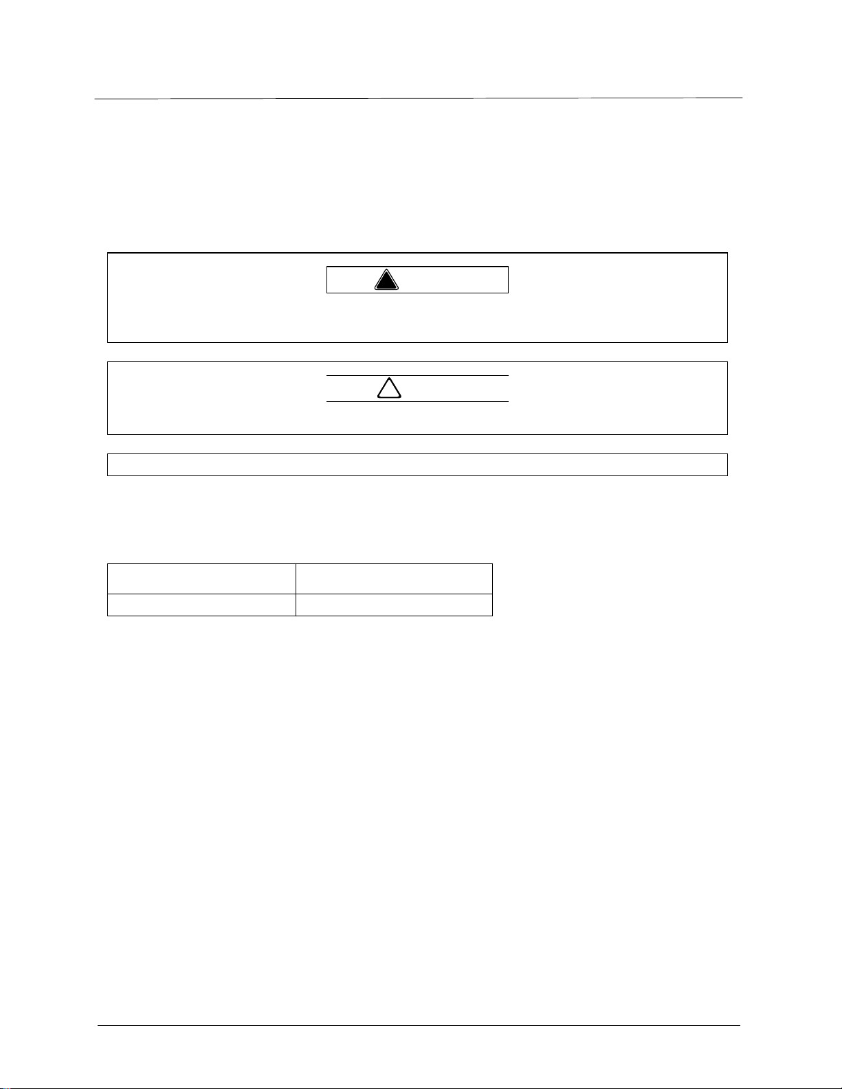
Warning and caution references have been made in this manual and should be adhered to for smooth
operation of the burner.
Warning
!
This symbol precedes information which, if disregarded, may result in injury to the user of the burner or to
others.
Caution
!
This symbol precedes information which, if disregarded, may result in damage to the burner.
NOTE: This symbol precedes information which is vital to the operation or maintenance of the burner.
Model designations are based on the type of fuel(s) to be fired and the amount of furnace pressure to
be overcome. Burner size is based on firing rate (rated input in Btu/hr).
Model Standards Fuel
Q Gas
The equipment must be installed in accordance with applicable local, state, or Provincial Installation
Requirements including the National Electrical Code (NEC) and Associated Insurance Underwriters.
Where applicable, the equipment shall be installed in accordance with the Provincial Installation
Requirements, or in their absence, the Canadian Gas Association (CGA) B149.1 and B149.2 and
Canadian Standard Association (CSA) B140 and B139 (for oil burners) Installation Codes shall
prevail. Authorities having jurisdiction should be consulted before installations are made. Gas burning
equipment shall be connected to flues having sufficient draft at all times to assure safe and proper
operation of the burner.
Q Series burners are designed to burn gas only as defined by ASTM D396-2010 specifications.
iv 750-437
Q Series Full Modulation
Page 7
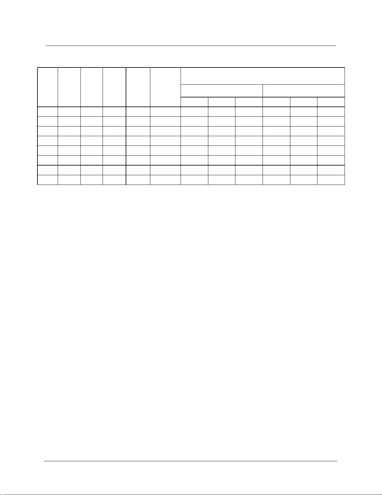
Q Series Full Mod Linkageless - Standard Specifications
Minimum Gas Pressure Required in Inches Water Column, by Gas Train
Burner
Gas Input
Model
Q6-055 550 13 1/2 1.0 1.50 2.10 - - 2.10 - -
Q6-075 750 18 1/2 1.0 1.80 3.60 1.70 - 3.80 2.00 -
Q6-100 1,000 24 1/2 1.0 2.25 6.40 2.90 2.60 6.60 3.40 2.60
Q6-130 1,250 30 1/2 1.0 2.95 10.10 4.20 3.50 10.60 5.20 3.70
Q6-150 1,500 36 1/2 0.75 * 13.60 5.70 4.80 14.20 7.00 5.10
Q8-175 1,750 42 3/4 1.0 3.45 15.50 4.80 3.50 16.30 6.60 3.90
Q8-200 2,000 48 3/4 1.0 3.80 19.80 5.70 4.10 20.80 8.10 4.60
Q8-250 2,500 60 3/4 0.75 * - 8.60 5.90 32.20 12.20 6.80
MBtu/hr
BHP
@80%
Eff.
Blower
Motor HP
Furnace
Pressure
(“w.c.)
Air Inlet
Orifice Size
7
(in.)
1 PSI Inlet Rated UL Trains 10 PSI inlet Rated UL Trains
1.00" 1.50" 2.00" 1.00" 1.50" 2.00"
*Orifice not required
NOTES:
1. Gas input based on natural gas at 1,000 Btu/cu. ft. and 0.60 gravity.
2. For total pressure at manifold, add furnace pressure.
3. Boiler overall efficiency of 80% estimated.
4. Blower wheel and motor HP is based on altitude up to 2,000 ft. above sea level. For higher altitude or 50 Hz.
applications, consult factory.
5. Firing at higher furnace pressures de-rates the burner by approximately 5% per 1/2” of additional pressure. Consult
factory.
6. Blower motor power: 115V / single phase / 60 Hz
7. See spare parts list for orifice plate part numbers.
Pressure Rating and Pipe Size
750-437
Q Series Full Modulation
v
Page 8
12X R
ØN
ØM
E
L
60°6X
30°
45°
90°4X
ØK
F
J
G
H
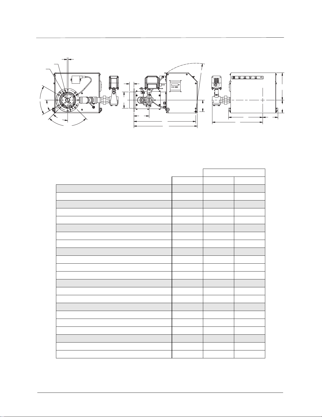
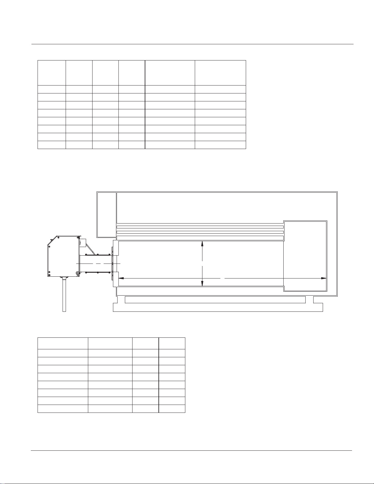
Q Series Full Modulation Linkageless Standard Dimensions
Accompanying dimensions are for layout purposes only.
Burner Model
DIM Q6 Q8
Length in inches
Overall burner length H 26 28 3/4
Width in inches
Center line to left side A 12 1/2 15 5/16
Center line to right side B 5 5/8 6 7/8
Height in inches
Center line to top D 10 11 7/8
Center line to bottom C 4 11/16 4 3/8
Hinge pivot point in inches
Mounting flange to hinge G 25 1/2 28
Hinge swing radius E 17 11/16 20 5/8
Center line to hinge F 4 3/16 3 7/8
Blast tube dimensions in inches
Extension L 3 1/2 3 1/2
Diameter K 6 8
Mounting flange dimensions in inches
Outer diameter of mounting flange N 12 14
Bolt circle diameter M 8 7/8 10 7/8
Mounting flange slot width R 5/8 5/8
Gas inlet dimensions in inches
Center line to main gas inlet P 18 1/2 19 1/2
Mounting flange to main gas inlet J 7 1/8 7 1/8
D
C
A
B
P
vi 750-437
Q Series Full Modulation
Page 9

Q Series Spare Parts List
PART DESCRIPTION - COMMON PARTS BURNER SIZE PART NUMBER
Ignition Transformer Q6 & Q8 832-04117-000
Light Indicator, White Q6 & Q8 881-00136
Light Indicator, Red Q6 & Q8 881-00137
Light Indicator, Green Q6 & Q8 881-00138
Light Indicator, Amber Q6 & Q8 881-00139
Air Switch Q6 & Q8 836-01598-000
Electrode Q6 & Q8 435-00694-000
Ignition Cable Q6 & Q8 832-04118-000
Fuse, Blower Motor ATDR 6A Q6 832-01161
Fuse, Blower Motor ATDR 15A Q8 832-01168
Fuse, Control Circuit ATQR 6A Q6 & Q8 832-01210
PART DESCRIPTION - BURNER MODEL PARTS BURNER SIZE PART NUMBER
Baffle Weldment Q6 009-04280-000
Baffle Weldment Q8 009-04282-000
Burner Housing (Blast Tube) Q6 160-01003-000
Burner Housing (Blast Tube) Q8 160-01002-000
Flange Gasket Q6 853-02539-000
Flange Gasket Q8 853-02540-000
Fan/Blower Unit Q6 894-04076-000
Fan/Blower Unit Q8 894-04111-000
Cover Q6 019-02395-000
Cover Q8 019-02398-000
PART DESCRIPTION - CONTROL COMPONENTS BURNER SIZE PART NUMBER
Display, Siemens Q6 & Q8 833-05071-000
Cable, Display Siemens Q6 & Q8 826-00315-000
Controller, Siemens Q6 & Q8 833-09334-000
Valve, Butterfly, 1.5” Full Port Q6 & Q8 940-01254
Actuator, Fuel Valve Q6 & Q8 269-00166-000
Coupling Q6 & Q8 819-00337-000
UV Scanner Q6 & Q8 994-15597-000
750-437
Q Series Full Modulation
vii
Page 10

Q Series Spare Parts List Continued
PART DESCRIPTION - GAS TRAIN COMPONENTS GAS TRAIN OPTION PART NUMBER
Regulator, Maxitrol RV 1 1/2” All Standard Pressure 817-00622
Valve, Gas Diaphragm 1 1/2” All Standard Pressure 940-01090
Bleed, Used with Gas Diaphragm Standard on All 940-01373
Valve, Gas Solenoid 1 1/2” All Standard Pressure 235-00368-000
Ball Valves 1 1/2” All Standard Pressure 941-00127
Regulator, Maxitrol RV 2” All Low Pressure 817-00617
Valve, Gas Diaphragm 2” All Low Pressure 940-01108
Bleed, Used with Gas Diaphragm Standard on All 940-01373
Valve, Gas Solenoid 2” All Low Pressure 235-00369-000
Ball Valves 2” All Low Pressure 941-00128
Regulator, Maxitrol 210 1” All High Pressure 817-00674
Valve, Gas Diaphragm 1” All High Pressure 940-01103
Bleed, Used with Gas Diaphragm Standard on All 940-01373
Valve, Gas Solenoid 1” All High Pressure 940-01191
Ball Valves 1” All High Pressure 941-00594
Gas Pressure Switch, High Ventless Standard on All 817-00977
Gas Pressure Switch, Low Ventless Standard on All 817-00876
PART DESCRIPTION - AIR INLET ORIFICE PLATE BURNER SIZE PART NUMBER
550 MBTU Burner (1.5” diameter) Q6 059-11448-000
750 MBTU Burner (1.8” diameter) Q6 059-11449-000
1000 MBTU Burner (2.25” diameter) Q6 059-11450-000
1300 MBTU Burner (2.95” diameter) Q6 059-11452-000
1750 MBTU Burner (3.45” diameter) Q8 059-11457-000
2000 MBTU Burner (3.8” diameter) Q8 059-11458-000
PART DESCRIPTION - DUCTED AIR INLET PARTS BURNER SIZE PART NUMBER
Instruction Drawing Q6 880-06261-000
Ducted-Air Adapter, 4" ID Q6 001-01680-000
Panel Side Plate With Ducted-Air Adapter Cutout Q6 136-04096-000
Instruction Drawing Q8 880-06262-000
Ducted-Air Adapter, 6" ID Q8 001-01681-000
Panel Side Plate With Ducted-Air Adapter Cutout Q8 136-04097-000
viii 750-437
Q Series Full Modulation
Page 11
CHAPTER 1 Intr oduction
Q series burners are completely assembled, wired, and tested at the factory.
Caution
!
Only factory authorized burner service personnel should start up, adjust, or service this equipment.
The operator must be familiar with the individual functioning of all controls to understand the operations and
procedures described in this manual.
1.1 — Description
Q-series full modulation units are forced-draft, direct-spark ignited, linkage-less burners controlled by an LMV37
programmer. They include safeguard functionality to insure the burner always returns to the ignition light-off
position for startup.
The Q-series modulating burners provide 550 to 2,500 MBTU/hr (~13 to 60 boiler horse power) against
furnace pressures of 0.75" w.c. or less (refer to burner specifications, page v). The Q6 has a 6" diameter firing
head and can fire up to 1,500 MBTU/hr (~36 boiler horse power). The Q8 has an 8" diameter firing head and
can fire up to 2,500 MBTU/hr (~60 boiler horse power). A field-installed air inlet orifice plate is required on Q6
burners firing below 1500 MBTU/hr and Q8 burners firing below 2500 MBTU/hr. See page viii for orifice plate
part numbers.
Q series burners are designed for automatic unattended operation except for periodic inspection and
maintenance. The control panel components require little attention except for occasional cleaning.
750-437
Q Series Full Modulation
1-1
Page 12
Introduction
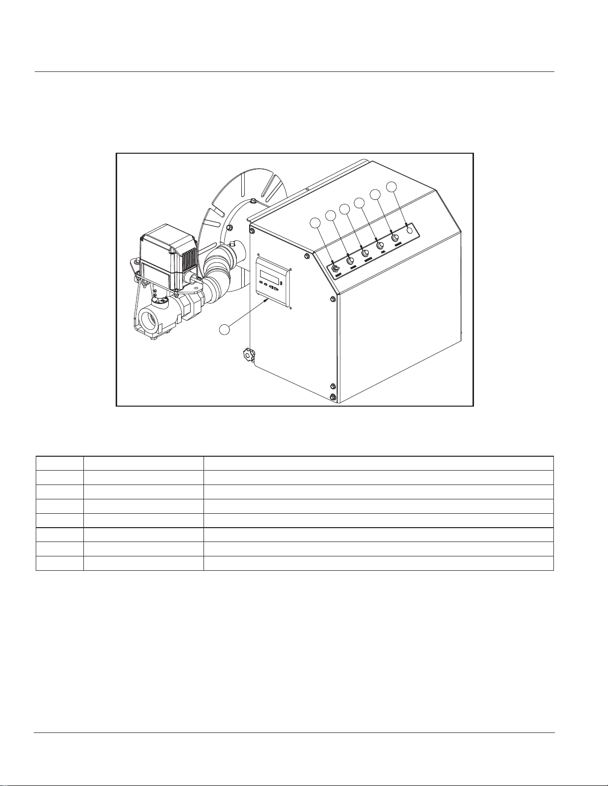
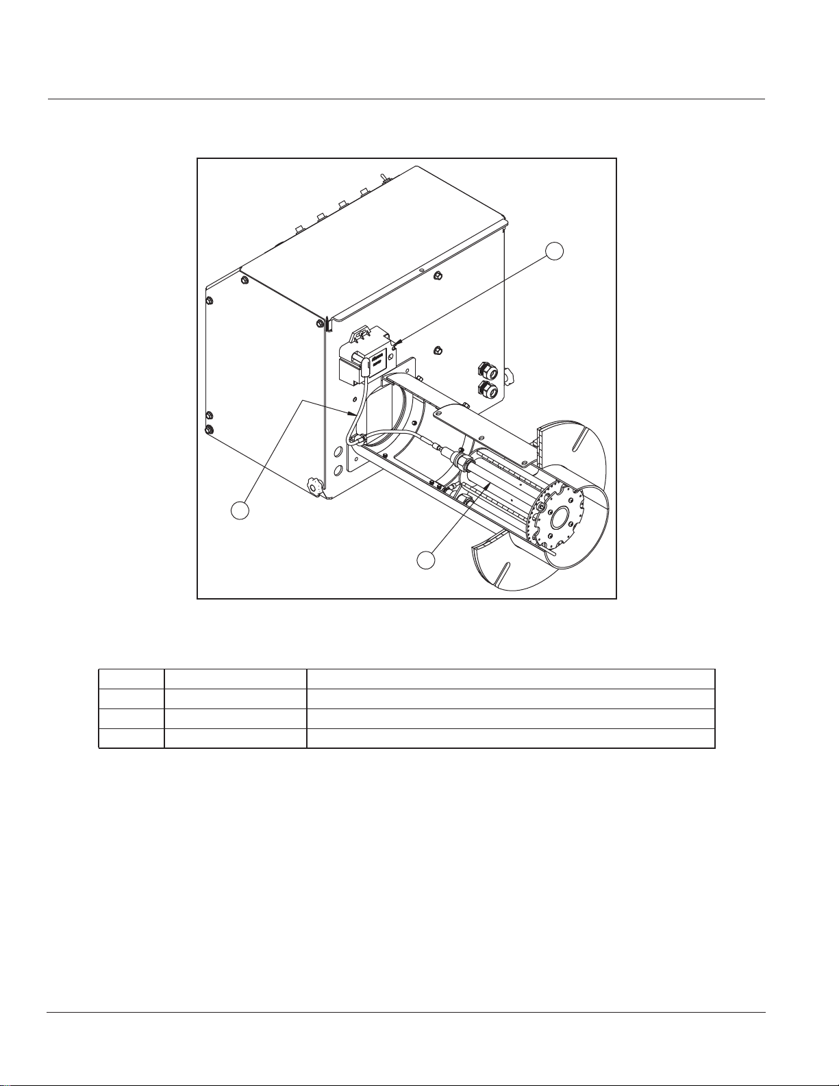
1.2 — Control Panel
The Q burner control panel has the control switch, status indicator lamps and LMV37 remote display mounted
on the panel exterior. The LMV37 control base, power supply, fusing and terminal strips are mounted on a
subbase inside the panel.
6
5
4
3
2
1
7
750-00532-000
FIGURE 1-1. Control Panel
Item Component Details
1 On/Off Control Switch Burner power switch
2 Power Light White lamp; illuminates when the control circuit is powered
3 Ignition Light Amber lamp; illuminates when the ignition transformer is powered
4 Fuel Light Green lamp; illuminates when the main fuel valves are powered
5 Failure Light Red lamp; illuminates when an LMV37 lockout fault occurs
6 Blank Blank lamp port
7 Control Display Control interface and status indicator
1-2
750-437
Q Series Full Modulation
Page 13
Introduction
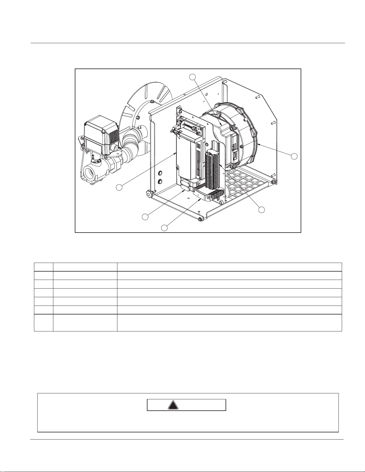
1.3 — Burner Control and Air Delivery
5
6
1
3
750-00533-000
2
4
FIGURE 1-2. Burner Control and Air Delivery
Item Component Details
1 LMV37 Control Combined flame-safeguard (FSG) and fuel-air-ratio-controller
2 Fuse holders Motor and control circuit fusing
3 Terminal Strip Field wiring interface
4 Power Supply 24Vdc for motor control speed input
5 DC modulation control The unit is fully modulated in response to the command signal sent from the LMV37.
6 DC (EC*) motor-fan
*Electronically Commutated
DC variable speed motor-fan unit with integral electronic controls. The unit is energized
by 115VAC power input.
1.3.1 — LMV37 Flame Safeguard and linkage-less fuel-air-ratio controller
The LMV37 incorporates burner sequencing functionality; flame detection; variable speed drive (VSD) control
and fuel-air-ratio control. Flame is detected by UV flame scanner. The LMV37 can modulate the burner from low
to high fire with servo control of the fuel metering valve and VSD electrical connection to the blower motor to
control fan speed (air volume).
Warning
!
Read the LMV37 manual and fully understand its contents before attempting to operate this equipment. Failure to do
so may result in serious personal injury or death.
750-437
Q Series Full Modulation
1-3
Page 14
1.4 — Direct Spark System
Introduction
1
2
750-00531-000 3
FIGURE 1-3. Direct Spark System
Item Component Details
1 Ignition Transformer Step up secondary high voltage ignition transformer
2 Ignition Cable 25KV high tension ignition wire.
3 Igniter ø1/8" electrode with quick connect
1.5 — Firing Head
Access to the firing head is provided by the side access panel.
1-4
750-437
Q Series Full Modulation
Page 15

Introduction
R
UV SCANNER
BURNER HOUSING
NUT
LOCK WASHER
UV SCANNER
BAFFLE PLATE
ELECTRODE
GAS MANIFOLD
ELECTRODE
ORIFICE PLATE
FIGURE 1-4. Burner Housing with a UV Scanner
SPRING PIN
ORIFICE PLATE
LOCK WASHER
STAND OFF
750-00509-001
750-00517-001
750-437
Q Series Full Modulation
BAFFLE WELDMENT
LOCK WASHE
SCREW
SCREW
FIGURE 1-5. Burner Housing, Exploded View
1-5
Page 16
Introduction
R
1.6 — Gas System
Gas is introduced into the combustion zone through multiple ports in the circular manifold. The full modulation
burner's LMV37 controls both the combustion air and fuel metering: it meters the fuel in proportion to fan speed
by adjusting the servo-driven gas metering butterfly valve.
Safety shutoff main gas valves are installed upstream of the gas-metering-butterfly valve and are controlled by
the LMV37 to open and close at the proper time in the operating sequence. The Safety shutoff valve models may
vary depending upon specific requirements.
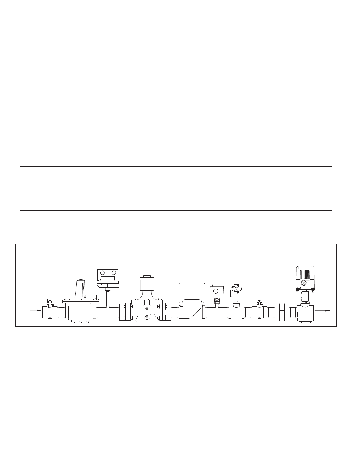
1.6.1 — Main Gas Train Components
Depending upon the requirements of the regulating authority, the gas control system and gas train may consist of
some, or all, of the following items:
Component Description
Gas Metering Butterfly Valve A servo-driven butterfly valve that controls the gas flow rate.
Gas Automatic Safety Shutoff Valves (SSOV(s)) Electrically operated safety shutoff valve(s) that open to admit gas to the burner. Stan-
dard U.L. burners include one diaphragm gas valve and one solenoid gas valve.
Gas Regulator Regulates gas train pressure to specified pressure required at the inlet of the gas train.
Input is set by the main gas pressure regulator adjustment.
Main Manual Gas Shutoff Valve A manual gas shutoff valve located at the gas train inlet (upstream of the regulator).
Main Manual Leak Test Valve A second manual gas shutoff valve located between the SSOV(s) and metering butterfly
valve. It provides a means of testing for leakage through the SSOV(s).
SUPPLY GAS
INTO GAS TRAIN
INLET
MAIN
MANUAL
GAS
VALVE
GAS
REGULATOR
LOW
GAS
PRESSURE
SWITCH
GAS
AUTOMATIC
SAFETY
SHUTOFF
VALVE
GAS
AUTOMATIC
SAFETY
SHUTOFF
VALVE
HIGH
GAS
PRESSURE
SWITCH
750-00529-000
LEAK
TEST
VALVE
MAIN
MANUAL
LEAK TEST
VALVE
GAS METERING
BUTTERFLY
VALVE
TO BURNE
MANIFOLD
INLET
FIGURE 1-6. Main Gas Train for Full Modulation (Q6-055 to Q8-250)
1.6.2 — Typical Gas Operation
Upon a call for heat and before flame ignition, the LMV37 flame safeguard starts the combustion air fan and
confirms the gas metering butterfly valve is in the low-fire position. When the combustion air switch proves
sufficient air, the control opens the gas safety shutoff valves. Provided the gas supply is connected and manual
cocks are open, gas then flows through the main gas train and gas metering butterfly valve into the burner gas
manifold. The gas streams out of the manifold through the multiple ports of the orifice plate (see Figure 1-5) and
mixes with the fan-fed combustion air.
1-6
750-437
Q Series Full Modulation
Page 17

Introduction
The control then powers the ignition electrode and initiates flame. The UV scanner and control confirms flame
presence and the burner progresses to main-flame operation. Main flame continues while flame is proven; the
external limit switches confirm good operating conditions, and a call for heat exists.
During main flame, the LMV37 receives a modulation input signal from a separate modulating controller that
directs the LMV37 to provide more or less heat. When the call for heat is satisfied, the LMV37 moves the gas
metering valve to the low-fire position and deenergizes the safety shutoff valves thereby shutting down the
combustion process. A post-purge period follows, and the heat exchanger is purged with air. After post-purge, the
burner returns to standby mode.
750-437
Q Series Full Modulation
1-7
Page 18

Introduction
1-8
750-437
Q Series Full Modulation
Page 19
CHAPTER 2 Installation
2.1 — Burner Requirements
Proper installation requires the following:
• Sufficient air supply - allow enough clearance at the bottom of the burner to allow the burner's
fan to draw the high-fire air volume without difficulty.
Warning
!
• A gas-tight seal - for maximum safety, the burner/boiler mounting must be sealed to prevent the
escape of combustion products into the boiler room. When properly installed, the burner
mounting flange and flange gasket will provide this seal. Make sure the flange gasket is installed
uniformly flat between the burner flange and the boiler front plate. When the burner flange is
tightened to the boiler, the gasket should be consistently flat around the entire flange
circumference; an improperly installed gasket will not provide a seal.
• Proper burner support where needed - the front plates on many boilers, including some Scotch
Marine types, are not strong enough to support the burner's weight. The burner has provision
for vertical support as detailed in Section 2.7.
2.2 — Factory and Field Wiring Overview
Electrical motor power and control circuit power are 115 volt, single phase, 60 cycle. Refer to the electrical
schematic diagram shipped with the burner. The schematic is also attached to the inside of the control panel
cover. Installer power connections are made at the control panel. Wiring from the panel to burner mounted
components is completed at the factory. Field wiring from the burner panel to boiler controls, low water controls,
and remotely located fuel valves is completed by the installer.
Caution
!
It is important to provide support for the panel cover when in the open position to prevent damage to the burner
and enclosed components.
750-437
Q Series Full Modulation
2-1
Page 20
Installation
2.3 — Draft Conditions
Automatic over-fire draft control or barometric draft regulators are not usually required except where the system
has a tall chimney. The exact height of a chimney requiring draft control is indeterminate, but draft regulation is
seldom needed for chimneys less than 50 feet high, especially with Scotch Marine or sealed firebox boilers.
2.4 — Combustion Air Supply
The space in which a burner operates must be supplied with adequate fresh air for combustion and ventilation
purposes. Fresh air supply must meet or exceed all code requirements. Consult with insurance carrier and/or
local authorities for specific regulations.
Warning
!
The boiler room pressure must be at least equal to the outdoor atmospheric pressure. Where fan ventilation is used,
air must be forced into the boiler room. Never exhaust air from the boiler room. Adjoining areas having exhaust fans
must be positively isolated from the boiler room.
2.5 — Combustion Chamber Recommendations
The combustion chamber dimensions should be adequately sized to prevent flame impingements.
2.5.1 — Non-Firetube Applications
A
B
C
(MIN)
FLOOR
2-2
STANDARD
FIREBRICK
BLOCK INSULATION
750-437
Q Series Full Modulation
Page 21
Installation
Combustion
Chamber Min.
Width (in.)
Chamber Min.
Burner
Size
A
(in.)
B
(in.)
C
(in.)
Q6-055 3.5 6 10 8 24
Q6-075 3.5 6 10 10 24
Q6-100 3.5 6 10 12 24
Q6-130 3.5 6 10 12 36
Q6-150 3.5 6 10 14 36
Q8-175 3.5 8 12 14 48
Q8-200 3.5 8 12 16 48
Q8-250 3.5 8 12 16 48
FIGURE 2-1. Non-Firetube Combustion Chamber Dimensions
2.5.2 — Firetube Applications
Combustion
Length (in.)
Burner Model Boiler HP A (in.) B (in.)
Q6-055 13 8 24
Q6-075 18 10 24
Q6-100 25 12 24
Q6-130 30 12 36
Q6-150 36 14 36
Q8-175 42 14 48
Q8-200 50 16 48
Q8-250 60 16 48
FIGURE 2-2. Firetube Combustion Chamber Dimensions
A
B
750-437
Q Series Full Modulation
2-3
Page 22
Installation
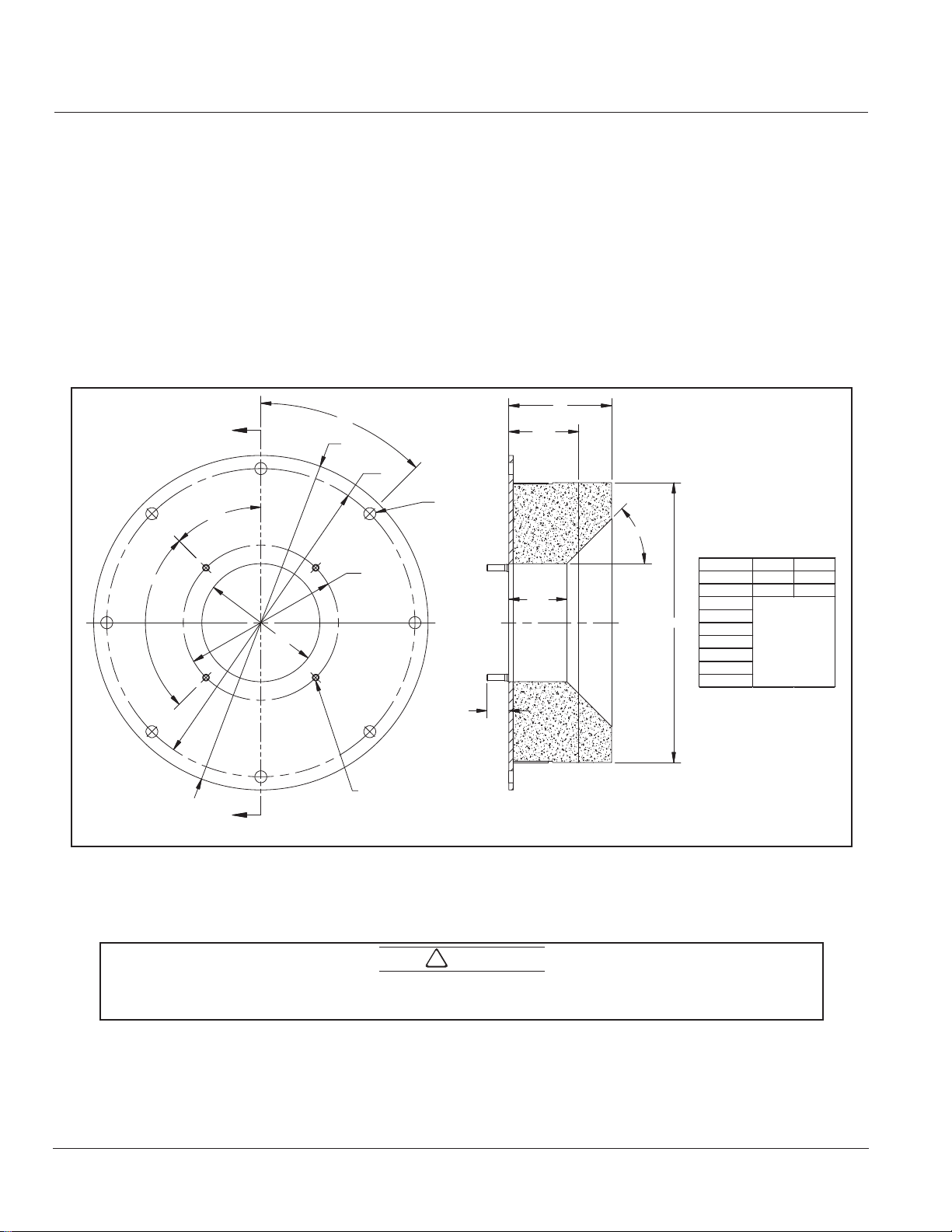
2.6 — Refractory Front Plate Requirements
A dry oven refractory is required only to protect surfaces not adequately protected by free circulating water. Basic
objectives of refractory installation include:
• Provide adequate combustion space
• Avoid flame impingement
• Protect surfaces not adequately water cooled
• Seal openings
Insulation should be provided between the refractory and the boiler base. Mineral wool or other material not
likely to settle is preferred. Insulation should be used between the refractory and front plate. Firebrick or
insulating firebrick should be set in high temperature bonding mortar with provision for expansion. Refer to
Figure 2-3 for refractory construction guidelines.
3.31
4.00
MIN.
"I"
45°
DIMENSION SIZE-6 SIZE-8
"A" 8.88 10.88
"B" 6.75 8.75
"C"
"C"
"D"
"E"
"F"
"G"
"H"
"I"
SIZED TO FIT BOILER
710-00897-000
A
45°
90°4X
"B"
"F"
"D"
"E"
"A"
P
3/8 STUDS
"G" x
1.25
P
"H"
A
FIGURE 2-3. Q Series Refractory Dimensions
To prevent leakage of combustion gases, the gasket must be resilient enough to seal any uneven areas
between the burner and the front plate.
2-4
Caution
!
750-437
Q Series Full Modulation
Page 23

Installation
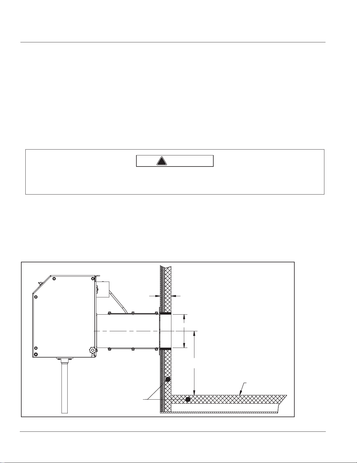
Prepare the boiler front plate and burner insertion as follows:
1. Determine burner mounting height. Locate and scribe a level
horizontal centerline across the mounting face.
2. Locate and scribe a vertical centerline. Be sure stud locations
line up where studs will have full support. If they don’t, or if
the opening is too large, a steel adapter plate, 3/8” minimum,
may be welded or bolted in place. Suitable anchors should be
provided to hold the refractory in place. The adapter plate
must be properly sealed (using insulating rope gasket) to prevent leakage of combustion gases.
3. Insulate burner insertion as shown in Figure 2-4
•Apply tack spray on the insert portion of the firing head that
will be wrapped.
•Wrap the insertion part of firing head with ceramic fiber
blanket (Kaowool). The wrap should be installed such that it
fills the 3/8” gap between the burner head outside diameter
(OD) and the refractory internal diameter (ID).
•Wrap the Kaowool with masking tape-this makes the
assembly easier to insert into the refractory. The wrapped
Kaowool must provide a snug fit between the refractory and
burner head. Rework if there are gaps.
•Trim off excess Kaowool.
•Apply ceramic-fiber rigidizer to the exposed Kaowool lip (see
figure 2-5). Protect/mask off the burner head so the rigidizer
only contacts the Kaowool lip; do not allow rigidizer to contact
any other part of the burner head.
FIGURE 2-4. Insulate Insertion
Note: the tack spray and masking tape hold material in place while the burner is installed into the
refractory. Following installation, heat exposure will burn away the tacking spray and masking tape.
4. Using insulating rope gasket, wrap the rope on the inside of
the bolt circle, looping the rope around the mounting
studs.Set the burner into position for mounting and tighten
into place. Standard burners are equipped with a four-hole
mounting flange.
5. Permanently support the burner using the pipe support con-
nections.
FIGURE 2-5. Rigidize Exposed Lip
750-437
Q Series Full Modulation
2-5
Page 24
Installation
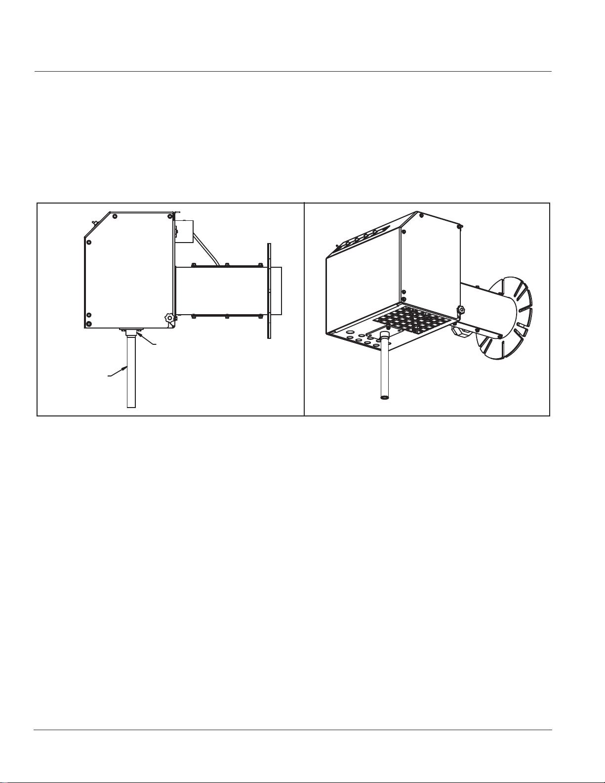
2.7 — Support Bracket Installation
Once the burner is installed, it must be supported by a suitable weight bearing surface. The burner is designed to
use the supplied support bracket kit number 880-06384-000. The bracket should be mounted to the burner
with the kit-supplied hardware.
A 3/4” NPS pipe, supplied by others, may then be cut to length and mounted so as to provide vertical support to
the burner.
SUPPORT BRACKET
(SUPPLIED WITH BURNER)
PIPE, 3/4" NPS (TOE)
SUPPLIED BY OTHERS)
750-00520-000
FIGURE 2-6. Support Bracket Installation
2.8 — Gas Piping
Gas service and house piping must supply the burner-required gas volume and pressure to the burner gas train
inlet. All piping must be in strict accordance with applicable codes, ordinances, and regulations of the supplying
utility. In the absence of other codes, piping should be in accordance with the following standards: “National
Fuel Gas Code” NFPA No. 54, ANSI No. Z 223.1 (for Canada, the Canadian Gas Association (CGA) B149 and
Canadian Standards Association (CSA) B140 codes shall prevail).
Full modulation gas train components upstream of the butterfly valve that are shipped loose should be mounted
by the installer as close to the burner as practical. Normally, the gas train is ordered to suit a particular code or
insurance regulation, such as Underwriters Laboratories Inc., CGA, or Factory Mutual.
Arrange gas piping to the burner so that the burner is accessible for servicing without requiring train disassembly.
The gas piping must be internally clean and free of foreign material. Before using in service, a leak test must be
performed.
2-6
Q Series Full Modulation
750-437
Page 25
Installation
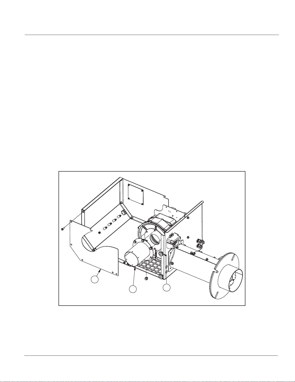
2.9 — Optional Ducted Combustion Air
An optional adapter port and slotted side panel allow combustion air to be ducted into the burner. The Q6
arrangement is a 4" OD inlet while the Q8 is a 6" OD inlet setup.
To equip the burner for ducted combustion air (item numbers refer to Figure 2-7):
• Change the side cover
1. Remove the cover lock-down thumb screw (Item 3).
2. Open the control cover (keep cover supported to prevent damage to it).
3. Remove the control panel side cover but retain the fasteners as they will be reused.
4. Install the slotted side cover (Item 2).
5. Replace the thumb screw (Item 3) to the position shown in Figure 2-7.
• Install the air inlet adapter
NOTE: If orifice plate required (Section 2.10) install between the blower and air inlet adapter.
1. Remove the (6) bolts from the fan-assembly inlet collar and air-pressure sensing line
2. Align the adapter (Item 1) and air-pressure sensing line bracket then replace and secure the 6 bolts. Use a
medium thread locker such as Loctite Blue to assure secure retention.
750-437
Q Series Full Modulation
2
1
FIGURE 2-7. Ducted Combustion Air
3
880-06262-000
2-7
Page 26
Installation
2.10 — Combustion Air Inlet Orifice Plate Installation
The Q burner size 6 and 8 use air-inlet-orifice plates to limit combustion air to the maximum firing rate needed
with respect to an application. The Q6 has a maximum rating of 1,500,000 BTU/HR. When used for the
maximum rate an air-inlet-orifice plate is not used. The same is true of the Q8 when used at its maximum rating
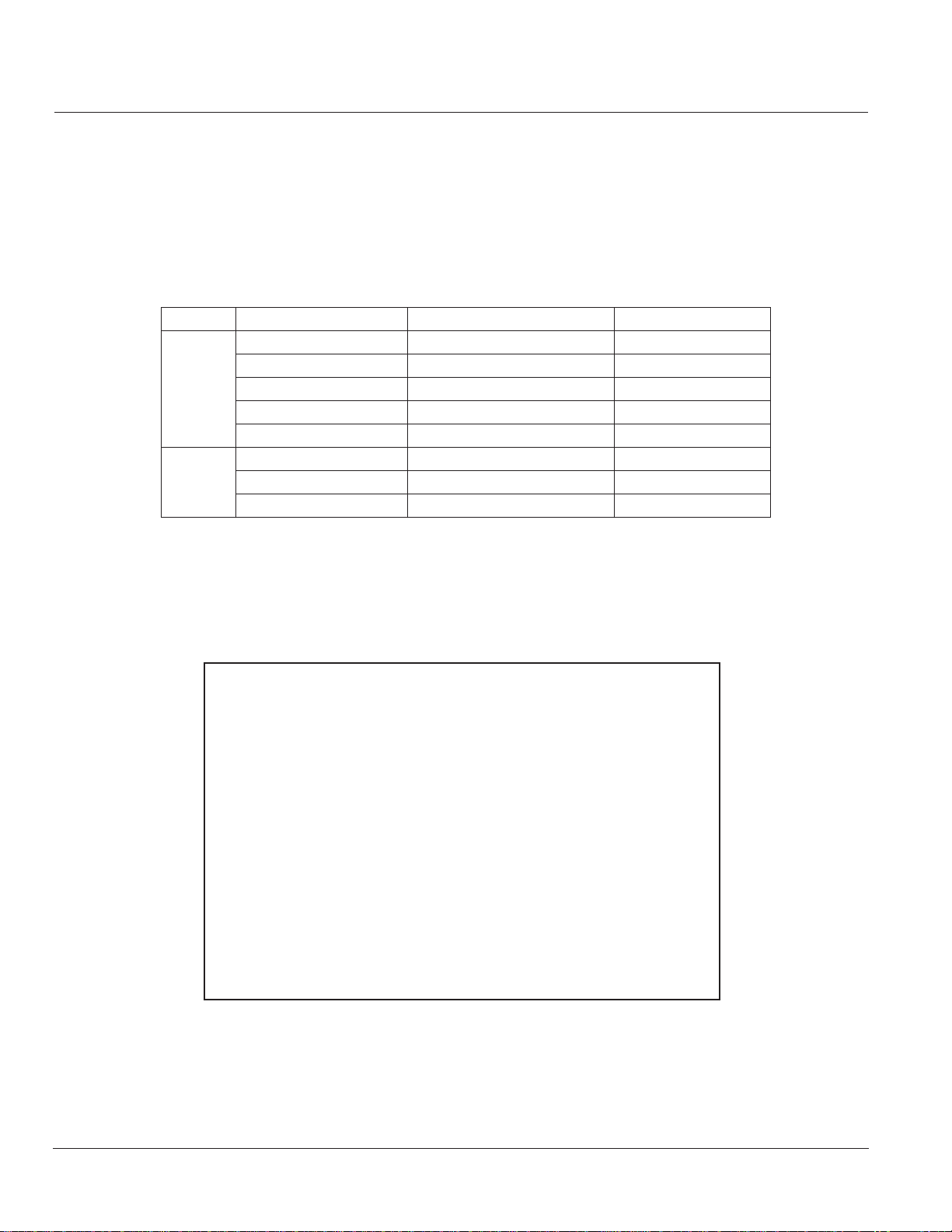
of 2,500,000 BTU/HR. For other firing rates, the chart below identifies the air-inlet orifice plate required:
TABLE 2- 1. Air Inlet Orifice Plate Application
Model Burner BTU/HR rating Air inlet Plate Part Number Orifice Diameter (in)
550,000 059-11448-000 1.50
750,000 059-11449-000 1.80
Q6
Q8
1,000,000 059-11450-000 2.25
1,300,000 059-11452-000 2.95
1,500,000 no orifice plate used -
1,750,000 059-11457-000 3.45
2,000,000 059-11458-000 3.80
2,500,000 no orifice plate used -
If an orifice plate is required, Install the provided plate to the blower assembly as shown in Figure 2-8 below.
Remove the existing (6) bolts from the fan-assembly inlet collar and air-pressure sensing line. Align the plate and
air-inlet sensing line then replace the (6) bolts. Use a medium thread locker such as Loctite Blue to assure
secure retention.
2-8
FIGURE 2-8. Inlet Orifice Plate Installation
750-437
Q Series Full Modulation
Page 27

Installation
2.11 — Installation Checklist
All burners are carefully assembled and tested at the factory, but before being placed in service, all connectors
should again be checked for looseness caused during shipment.
Check:
• Electrical terminals in the control panel and on all electrical components.
• Pipe fittings, unions and tube connections.
• Nuts, bolts, screws.
Before connecting electrical power to any component, be sure the supply voltage is the same as that specified on
component nameplates.
Before firing, make sure that the burner mounting flange is properly sealed to the boiler front plate.
It is the installer’s responsibility to identify the main electrical power disconnect and the manual shut-off valve on
the gas supply drop-line to the burner.
Make certain that the operator in charge is properly instructed in the operation and maintenance procedures.
Caution
!
Before opening the gas shutoff valves, read the regulator instructions carefully. Open the shutoff valve slowly to
allow inlet pressure to build up slowly in the regulator until it is fully pressurized. Opening the shutoff valve quickly
will damage the regulator.
Do not exceed the regulator pressure ratings.
750-437
Q Series Full Modulation
2-9
Page 28

Installation
2-10
750-437
Q Series Full Modulation
Page 29

CHAPTER 3 Operation
NOTE: Separate modulating load controller
required for operation.
3.1 — Preparations for Starting
The following items must be satisfied before any attempt is made to operate the burner:
• Electric, fuel, water, and vent stack connections are complete and all connections are confirmed tight.
• The operator is familiar with the boiler components and controls.
• The operator is familiar with the burner and understands: the burner components and controls (Chapter 1);
the LMV3 sequence of operation; and the burner wiring to the boiler controls per the burner wiring diagram.
In addition, the following checks must be made:
Item Check
Boiler
Burner
Boiler water level.
Be sure all boiler valves are installed correctly and positioned properly.
Set the high limit control slightly above the desired temperature.
Set the operating control to the desired temperature or pressure.
Set modulating controls at the desired temperature or pressure.
Check the electrical power supply to the burner in accordance with the nameplate voltage.
Check the fuel control actuator for proper movement of the fuel metering valve.
Refer to the Siemens LMV3 manual for additional information.
3.1.1 — Gas Supply
A representative of the gas utility should turn on the gas. Confirm sufficient pressure exists at the entrance to the
gas train (use test gauge upstream of the burner regulator). The gas pressure regulator must be adjusted to the
pressure required.
3.1.2 — Burner Settings
To ensure reliable and safe burner performance, the fan speed and gas settings must be checked and adjusted
prior to placing the burner into initial service, or after conducting any service work that may have altered the
settings. The modulating firing rate is controlled by a temperature or pressure sensor in conjunction with a
controller capable of generating a 4-20 mA output signal (minimum 500-ohm impedance) or a floating bumping
750-437
Q Series Full Modulation
3-1
Page 30

Operation
circuit. For optimal efficiency, the controller used should be capable of PID load control. The purge rate, ignition
position, minimum firing rate, maximum firing rate and fuel-air ratio throughout the firing range is determined by
settings made in the Siemens LMV37 display. Refer to the Siemens LMV37 operation manual for further
information.
3.1.3 — Combustion Settings
Fuel and air flow rates are individually adjusted at low fire and at high fire to achieve rated heat input, firing rate
turndown, optimum efficiency, and safe operation. Refer to the nameplate inside the control panel for fuel input
ratings and corresponding manifold pressures.
3.1.4 — Test Equipment
Combustion tests and pressure readings should be conducted on-site and typically requires equipment such as:
• Combustion analyzer with O2, CO2, and stack temperature indication.
• U-Tube manometer, or pressure gauge, to measure gas pressure.
• Manometer to measure draft pressures.
• Voltmeter/Ammeter.
Warning
!
Read the LMV37 manual and fully understand its contents before attempting to operate this equipment. Failure to observe this warning may result in serious personal injury or death.
3.2 — Burner Sequence Overview
Basic overview of the control's normal sequence of operation is provided herein. Refer to the LMV37 manual for
additional sequence-of-operation detail and the burner-wiring diagram to a better understanding of how the
boiler and burner limit devices impact sequence of operation.
3.2.1 — Normal Automatic Sequence of Operation
In automatic operation, the burner cycle proceeds through standby, pre-purge, ignition, main flame operation
(released to modulate and load controller is driving the firing rate), post-purge and return to standby.
During main-flame operation, the burner firing rate is modulated by a load controller in response to the heat
exchanger's pressure or temperature until the operating control* contacts open and end the call for heat.
*operating control contacts may be either an individual operating control device or in a controller which incorporates load controller capability.
The LMV3 operation should be tested when:
• the burner is initially placed into service;
• a control is replaced; or
• the scheduled maintenance program so indicates.
3-2
750-437
Q Series Full Modulation
Page 31

Operation
Normal automatic operation is detailed in Table 3.1 and the corresponding AZL indications are shown in Fig 3-1.
TABLE 3- 1. Normal Automatic Sequence Of Operation
LMV37
Sequence
Standby 12 Standby OFF No call for heat exists
Call for heat made 22 Fan motor on Ph 22
24 Air volume increased for pre-purge Ph 24
Pre-purge 30 Pre-purge Ph 30 _XX
36 Air volume adjusted for ignition Ph 36
Ignition 38 Ignition transformer energized Ph 38
Main fuel 40 Fuel valve Ph 40
42 Ignition Ph 42
Delay before
modulating
Released to
modulate
Call for heat ends 62 Fuel and air adjust to the low-fire rate Ph 62
70 After-burn time (confirms no flame) Ph 70
72
Post-purge 74 Mandatory post-purge time Ph 74 _XX
78 Optional post-purge time Ph 78
Low-fire position 10 Home run (fuel actuator referencing) Ph 10 Actuator self-check
Phase Action
44 Interval 1 pilot stabilization Ph44 _XX
Operation (LMV37 responding to
60
modulating control input)
Air volume is adjusted to the postpurge rate
oP: YY.Y where YY.Y = % firing rate
AZL DISPLAY
TEXT
Ph 72
INDICATOR
CMIVF
Gas press. switches must
Ignition/main flame
be made to progress to
ph24
where XX = countdown
timer in seconds
where XX = countdown
timer in seconds
where XX = countdown
timer in seconds
User added time (via
parameter)
Note
FIGURE 3-1. AZL Status Indications for Normal Operation
Note: In this manual, AZL display text is shown in brackets, e.g. “{OFF}.”
750-437
Q Series Full Modulation
3-3
Page 32

Operation
3.2.2 — Standby
The burner is in standby and ready to respond to a call for heat when
• All power supply switches are closed and power is present at the control panel as indicated by the burner's
illuminated white “power” light.
• The high limit control contacts are made. If the high limit has tripped (contacts open), it must be manually
reset.
• The burner's On/Off control switch is in the “ON” position.
• The AZL displays {OFF}.
3.2.3 — Startup
While burner is standby/{OFF}, and when the operating pressure/temperature falls below the operating control
set point the operating control contacts make/close. If all other devices in the limit string are made and the burner
switch is ON, the control sees a “call for heat” and then sequences through startup as follows (commentary in
italics)
{Ph22} = Fan motor on - The burner energizes the fan
{Ph24} = Traveling to pre-purge position - Airspeed ramps up to high-fire air delivery rate
{Ph30} = Pre-purge countdown timer (30 sec) - Control confirms combustion air pressure is proven and then
pre-purges the heat exchanger to rid it of any possible accrued flammable vapors. The control displays {Ph30
XX.X} where “XX.X” is the countdown in seconds.
{Ph36} = Traveling to ignition position - Airspeed and gas valve opening are positioned for ignition at the LMV's
P0 position.
{Ph38} = Pre-ignition Time - (ignition transformer ON) - Direct spark transformer energizes the electrode
{Ph40} = 1st Safety Time - (safety shutoff valves ON) - Gas delivered to the combustion zone.
{Ph42} = 1st Safety Time (ignition transformer OFF) - Direct spark period terminates and flame presence
confirmed.
{Ph44} = Interval 1 - Flame stabilization
3.2.4 — Operation - Automatic Modulation
• The Control is in phase 60 and burner modulation is released to the load controller. The AZL presents {oP:
YY.Y} where “YY.Y” indicates the percent firing rate.
• The “YY.Y” firing rate is typically proportional to the difference between the load controller's set point and the
currently measured temperature or pressure value: large differences result in high firing rates with the firing rate
diminishing as the measured value approaches the setpoint value.
3.2.5 — Automatic Shutdown
• When the call for heat is satisfied, the operating control contacts open and the LMV3 control enters phase 62
where it commands the airspeed and fuel valve position to the P1 low-fire position.
3-4
Q Series Full Modulation
750-437
Page 33

Operation
{Ph70} = The safety shutoff valves are de-energized/closed and the burner's "Fuel" lamp turns off.
{Ph72} = Traveling to post-purge position - Airspeed ramps up to high-fire air delivery rate
{Ph74} = Mandatory-post-purge time - High-fire air post-purges the heat-exchanger for the minimum-time
requirement. The display shows {Ph74 XX.X} where “XX.X” is the post-purge countdown timer in seconds.
{Ph78} = Optional-post-purge time - Additional post-purge time can be added via parameter adjustment.
{Ph10} = Home Run Position. Following post-purge, the burner motor stops. The gas actuator positions to home
which is the actuator's self-check of its optic position sensors.
• Burner returns to standby Phase 12, the AZL displays {OFF} and is ready for startup on the next call for heat.
Note: LOW WATER - If a low-water condition occurs, the burner shuts down as in “Automatic Shutdown” and the
AZL displays {OFF}. When the water level is restored and the low-water safety device resets. Provided all other
recycling limits are made and the burner switch is on, the burner will fire again when the operating control
contacts make (receives a new “call for heat”).
3.2.6 — Manual Shutdown
To manually shut off the burner:
• Turn the burner switch to OFF. The burner shuts down as in “Automatic Shutdown.”
• When the burner displays {OFF}, close the gas train's shutoff and main leak-test manual valves.
Automatic operation can not resume until the operator has determined it is safe to operate the system and
returns the gas valves to their open position and turns the burner switch to ON.
3.2.7 — Safety Shutdown
A safety-loop failure presents as an LMV3 error code 22 where the display alternates {Loc.c: 22} and {Loc.d:
X} (“x” being a diagnostic code value). A flame failure (loss of flame signal) presents as an LMV3 error code 93
where the display alternates {Loc.c: 93} and {Loc.d: X}. Either open safety-loop or loss-of-flame-signal
condition will cause the LMV3 to rapidly de-energize the safety-shutoff-fuel valves and the blower motor.
Shutdowns may result from motor overloading; low water; interruptions in either fuel or power supply; insufficient
combustion-air-pressure; tripped circuit breakers; blown fuses; or other interlock devices.
A safety shutdown will illuminate the burner's red “FAILURE” light and (if so equipped) energize an audible
alarm.
The failure's root cause must be determined and corrected before any attempt is made to restart the burner.
Gas pressure fault - If a high or low gas pressure condition occurs during burner operation, the burner shuts down
as in “Automatic Shutdown.” The AZL presents a fault indication and error code 20 condition by alternating
{Loc.c: 20} and {Loc.d: X} in the display. The pressure condition must be corrected and the respective gas
pressure switch is manually reset before attempting a burner restart.
750-437
Q Series Full Modulation
3-5
Page 34

Operation
Reference the “LMV Troubleshooting” section duplicated in this manual for additional “{Loc. C}” error code and
“{Loc.d}” diagnostic information.
3.3 — Gas Pressure Regulator Setup
To determine the initial pressure setting of the gas pressure regulator
(for gas trains consisting of a regulator and two safety shut off valves) a
good rule of thumb is to adjust the regulator set point to twice the high
fire manifold pressure. If using a Siemens gas train, with the regulator
being the last component before the gas metering butterfly valve, set
the regulator set point to 1.5 times the high fire manifold pressure.
Fuel/air ratio curve setup may then proceed.
3.3.1 — Regulator Spring Selection
After determining the pressure setting as described above, use Table
3.3 to select the appropriate regulator spring.
TABLE 3- 3. Regulator Spring Selection
SPRING COLOR
Brown 1.0 - 3.5
Plated 3.0 - 6.0
Pink 3.0 - 8.0
Blue 5.0 - 12
Red 10 - 22
PRESSURE
RANGE (“WC)
TABLE 3- 2. Burner Manifold Pressure*
Manifold
Burner MBH
550 0.65
750 1.00
Q6
Q8
*Excludes furnace pressure. Add furnace
pressure to determine total manifold
pressure for your specific application.
1,000 1.70
1,300 2.25
1,500 3.10
1,750 2.30
2,000 2.50
2,500 3.50
Pressure
(“WC)*
Where possible, spring selection should be made so that the pressure setpoint falls within the upper 50% of the
spring range. For example, for a setpoint of 5.0”, the Plated spring (3-6” range) is preferable to the Pink spring
(3-8” range).
3.4 — Gas Train Leak Test
Note: In this section, AZL display text is shown in brackets, e.g. “{OFF}.”
A gas safety shutoff valve leak test (Bubble Test) must be performed prior to any initial commissioning or
subsequent maintenance of the burner and gas train system. This test should be performed periodically to ensure
no leakage of valves in their closed or de-energized position (refer to the valve manufacturer's procedures). The
unit should be taken out of service if the unit fails any part of the gas valve leak test. Any defective part must be
replaced prior to putting the equipment back into service.
Refer to Figure 3-2 when following this procedure:
3-6
Q Series Full Modulation
750-437
Page 35

Operation
[3]
[6]
[8B]
[4] [5]
[7]
TO
BURNER
GAS
TRAIN
INLET
[1]
[2]
8A
o
45
1/2”
FIGURE 3-2. Gas Train Leak Test
Caution
!
Before opening the manual gas shutoff valves, read the regulator instructions carefully. Open the shutoff valve
slowly to allow inlet pressure to build up slowly in the regulator until it is fully pressurized. Opening the shutoff
valve too quickly will damage the regulator.
1/2”
45
o
Do not exceed the regulator pressure ratings.
NOTE: for V48A equipped gas trains see 4.2.1 for additional information.
3.4.1 — Leak Test Procedure
Fill the gas train for leak testing (burner will go through startup with the blower running, but the burner is not
intended to be fired at this time as the closed leak-test valve blocks gas to the burner).
1. CONFIRM BURNER IS READY FOR LEAK-TESTING THE GAS TRAIN:
•Set burner control switch to OFF position.
•The AZL displays {OFF}
•CLOSE the main leak test valve [7] entirely.
•Minimize the chance that gas pressure switches will interfere with the initial setup:
Set the low gas pressure switch [3] to the lowest setting.
Set the high gas pressure switch [6] to its highest setting and press its reset.
NOTE: gas pressure switches will be tested and set following the LMV37 commissioning and tuning.
•Set the operating control so burner will run when the burner switch is turned ON.
•Partially open the manual shutoff cock [1].
•Reset the low gas pressure switch if required
750-437
Q Series Full Modulation
3-7
Page 36

2. TURN THE BURNER SWITCH ON.
If the burner blower does not start:
If the display continues to show {OFF} with the burner switch ON, then close the manual shutoff cock [1].
Troubleshoot the limit circuit and correct the situation so that the AZL “Heat request from controllers” LCD
bar beneath the icon turns solid with when the burner switch is turned ON. Repeat from Step 1.
FIGURE 3-3. Request for Heat
If the burner blower starts:
The burner will progress and display the following stages:
Operation
{Ph22} = Fan motor on
{Ph24} = Traveling to pre-purge position
{Ph30} = Pre-purge countdown timer (30 sec)
{Ph36} = Traveling to ignition position
{Ph38} = Pre ignition Time
Burner light off attempt at factory P0 setting
{Ph40} = 1st Safety Time (ignition transformer ON)
{Ph42} = 1st Safety Time (ignition transformer OFF)
{Ph44} = Interval 1
As the closed leak test valve [7] is blocking fuel delivery, the LMV37 will not detect flame during its trial for
main flame and will safety shutdown with the burner panel's red failure light illuminated. The LMV3 safety
shutdown should de-energize/close both safety shutoff valves [4] and [5]. If a safety-shutoff valve fails to
close, close the manual shutoff valve [1]. Do not proceed further until you correct the problem. If [4] and [5]
closed, pressurized gas should be trapped between [4] and [7] and you may proceed to the next step.
3. LEAK TEST THE DOWNSTREAM SAFETY SHUTOFF VALVE [5].
Release the gas trapped between and main gas safety shutoff valve [5] and manual cock [7] by opening the
leak test cock [8B]. After the trapped gas has been vented, continue to perform a bubble test for any leakage
through the safety shutoff valve [5]. Bubbles will appear if gas is leaking past [5]. If bubbles continue, close
the main shutoff valve [1], correct the valve [5] problem and retest 10 times before proceeding. If no leak,
close test cock [8B] and continue to the next step.
4. LEAK TEST THE UPSTREAM SAFETY SHUTOFF VALVE [4].
Release gas pressure at test cock [8A] and bubble test for any leaking through auxiliary safety shutoff valve
[4]. If you do not observe a leak, close test cock [8A] and go to the next step. If safety shutoff valve [4] leaks,
correct the problem and retest 10 times before proceeding.
Procede only when it is established there are no gas leaks.
3-8
Q Series Full Modulation
750-437
Page 37

Operation
5. RESET MANUAL VALVE OPEN/CLOSE POSITIONS BEFORE RESUMING NORMAL OPERATION.
Confirm:
•Manual-leak test valves [8A] and [8B] are closed.
•All safety shutoff valves are operating normally.
•Confirm manual cocks [1] and [7] are open.
3.5 — Combustion Emissions and Efficiency
The Q burner should be tuned so combustion results match the respective firing rate range in Table 3- 4:
TABLE 3- 4. Emissions Guidelines
Firing
Rate
HIGH
FIRE
MID
FIRE
LOW
FIRE
CO
O
2
3.0 15.0 10.0 11.7
3.5 18.0 9.6 11.5
4.0 21.0 9.4 11.2
4.5 24.5 9.1 10.8
5.0 28.1 8.8 10.4
5.5 31.9 8.5 10.0
6.0 35.9 8.3 9.8
6.5 40.3 8.0 9.5
7.0 44.9 7.7 9.2
8.0 55.6 7.5 8.5
Excess Air
Natural Gas
2
CO
2
Propane
3.5.1 — Carbon Monoxide
Warning
!
Carbon Monoxide is a colorless, odorless toxic gas resulting from incomplete combustion of gas. It can kill
quickly with no warning.
Know the signs: headaches, nausea, dizziness, breathlessness, collapse, loss of consciousness.
Carbon Monoxide Parts per Million (PPM) values should be kept to a minimum; it is reasonable to expect
attainable levels below 50 PPM. Certain heat exchanger characteristics such as furnace dimensions, vessel
construction, etc., can make low CO difficult to achieve; consequently, continued attention to levels is advised.
Most codes limit permissible CO amounts to below 400 PPM.
3.5.2 — Efficiency and Stack Temperature
A high net stack temperature indicates wasted heat. Net stack temperature is obtained by subtracting the
ambient air temperature from the flue gas temperature. Stack temperature should be as low as possible without
causing flue gas condensation.
750-437
Q Series Full Modulation
3-9
Page 38

Operation
Stack heat loss can be reduced by (a) decreasing stack temperature through improved heat transfer or (b),
decreasing the flue gas volume by decreasing excess combustion air. A certain amount of excess air is necessary
to complete combustion. See Table 3- 4 for excess air guidance.
Stack temperatures vary by system type but in clean, well-tuned vessels you may expect the following:
Hot Water Vessels: Stack temperature is typically 75-100° F above the water temperature.
Steam Pressure Vessels: Consult saturated steam tables to determine approximate stack temperature. Stack
temperature is normally 75 to 100°F over the saturated steam temperature. As an example, a 10 psig lowpressure steam system at 80° F ambient air, can indicate a stack temperature of approximately 320°F. A 125
psig system under the same conditions increases the stack temperature to approximately 453°F.
3.6 — LMV3 Settings
This section guides you through adjustment of the fan speed and gas valve setting for the LMV3’s ignition point,
P0, and the low to high-fire points P1 through P9. A combustion analyzer is required. A pen and paper should
be on hand to keep a written record of the settings. Final setting values should be recorded in the startup service
report found at the back of this manual.
Warning
!
The Q burner LMV3 has ignition point P0 and fuel-curve points P1 through P9 entered in the control. These points,
however, must be adjusted to the specific application the burner is being installed on. If reasonable care is not taken
to tune combustion points to the application, hazardous combustion conditions may result.
Note:
Read Section 3.6 in its entirety before making any adjustments.
The burner status is presented via the AZL and burner panel indication lights. Figure 3-4 shows how certain AZL indications are also indicated by the burner panel lights:
Display Representation - In this section, text on the AZL display is shown either graphically OR as text enclosed in
French brackets (example below).
Button References - The AZL panel has five buttons. This section uses parentheses to reference their single and combinational use as follows:
(F), (A), (-), (+), ( enter), (reset)
(ESC / - & +) = pressing (-) and (+) buttons simultaneously and,
(VSD / F & A) = pressing (F) and (A) buttons simultaneously.
Manual Lockout - In the case of an emergency, the installer can manually lockout the LMV3 by simultaneously pressing
( enter) in combination with any other button. Following lockout, the AZL will display {Loc:c: 167} {Loc:d: 2}.
Press (reset) until {rESET} appears.
3-10
Q Series Full Modulation
750-437
Page 39

Operation
FIGURE 3-4. AZL Display
3.6.1 — Password Entry / Login
With power on (panel's white indicator is illuminated) and Burner switch in the OFF position, the control
displays:
{OFF}
Reset any errors by holding the (reset) button for 1 to 3 seconds. To access LMV3 parameters, you'll need to
enter the password “YYYYY”.
Press and hold (VSD / F & A) until the control displays:
{CodE}
The display then changes and appears with a flashing bar at the bottom left and is ready to accept password
entry:
The (-) and (+) buttons will scroll the AZL through its character set. To enter the first “Y” of the password, press
(-) once; a blinking Y should appear:
750-437
Q Series Full Modulation
3-11
Page 40

Operation
Press ( enter) to accept the value. The display cursor position advances to accept the second character:
Press (-) then ( enter) four more times to enter “Y” five times; the sixth underscore will be flashing following
entry of the fifth “Y”:
Press ( enter) to enter the password. A successful login will briefly display
{PArA}
followed by:
{400: SEt} “400” flashing
An incorrect entry attempt will display:
{Error} then {OFF}
If the attempt fails, repeat the steps from the beginning of this section.
Note: The following conditions will exit you from AZL parameter entry (log out):
•Power to the LMV3 is disconnected or cycled.
•The AZL is unplugged from the LMV3.
•Timeout (AZL inactive for a time period greater than parameter 127 setting).
•While in a parameter group with {X00: SEt} (X = 1,2,3 etc.), hold (ESC / - & +) until {CLr CodE} displays.
To regain access after a log out, repeat the password entry steps.
3-12
750-437
Q Series Full Modulation
Page 41

Operation
3.6.2 — Initial Fuel-Curve Point Adjustments
Notes:
• You must be password entered to make changes to curve point values.
• The gas and air set values presented in this instruction are for example only.
• Air-fan speed is adjusted with the (VSD / F & A) buttons.
• Gas-valve actuator position is adjusted with the (A) button.
• Confirm curve-point emissions are within expected ranges per emission table 3.3 in section 3.6
Warning
!
Although the burner was fire tested at the factory, be certain to check fuel valve actuator coupling for tightness before
making any adjustments to fuel or air. Be certain the valve is fully closed when the control indicates “0” degrees open.
Caution
!
• The installer is responsible to ensure that safe fuel-to-air ratios are being maintained.
• If an AZL (+) or (-) button is held continuously when adjusting an actuator position value, the value will change at a
progressively faster rate.
• When increasing a setting, increase air and follow with fuel.
• When decreasing a setting, lower fuel first and then air.
Warning
!
Rapid temperature changes to the heat exchanger can cause major damage due to thermal shock.
It is imperative when starting a cold vessel for the first time the vessel be warmed slowly, either by allowing the burner
to cycle for intermittent periods or leaving at low fire. This should be done until the vessel is up to normal operating conditions.
A) Access parameter set 400
If the control displays
{400: SEt} “400” flashing
then go to B. Otherwise: Press (ESC / - & +) repeatedly until the display shows:
{OFF}
Press (VSD / F & A) until the control displays:
{400: SEt} “400” flashing
750-437
Q Series Full Modulation
3-13
Page 42

Operation
B) Advance control to standby PH12
From the {400: Set} screen, press ( enter) and the control displays:
{run}
Press ( enter) again and the control displays:
{Ph12} = Standby
Test P0 Ignition Point
NOTE:
The fan speed is measured in percentage. The gas metering valve is measured in degrees open. At P0 light off:
The Q-burner-fan speed should be approximately 20-30%
The gas-metering-valve angle should be between 2 - 12° open.
Tuning the P0 point may require repeated efforts to ignite the flame and find the required gas/air mix for consistent, stable ignition. If the burner fails to light, turn the burner switch off before resetting the control so you have the opportunity
to adjust the P0 setting.
In the sequence below, the burner executes trial for ignition/main flame during PH42 and PH44.
Turn the burner switch ON. The burner progresses through pre-ignition phases and trial for flame:
{Ph22} = Fan motor on
{Ph24} = Traveling to pre-purge position
{Ph30} = Pre-purge countdown timer (30 sec)
{Ph36} = Traveling to ignition position
{Ph38} = Pre ignition Time
Burner light off attempt at factory P0 setting
{Ph40} = 1st Safety Time (ignition transformer ON)
{Ph42} = 1st Safety Time (ignition transformer OFF)
{Ph44} = Pilot stabilization
If light off is successful, go to step e. Otherwise, continue to c.
C) Failed ignition - Reset LMV
Following a failed light off attempt, the burner locks out and displays alternating error/fault messages:
{Loc:c: X} and {Loc:d: Y}
Turn burner switch OFF
Press (reset) until display shows {rESET}
The control sequences to {Ph 10} home run, then
{OFF}
3-14
750-437
Q Series Full Modulation
Page 43

Operation
D) Access the P0 parameter
With the display showing {OFF}
Press (VSD / F & A) to enter parameters and the display shows:
{400: SEt} (“400” flashing)
press ( enter) and control displays: {run}
Press (ESC / - & +) and the control prompts you with the P0 setting:
{P0: : GG.c}
where “GG.c” = current fuel-valve open angle in degrees.
E) Adjust P0 setting:
AIR- Airspeed setting is typically between 20 and 30%. If airspeed needs adjusted, press and hold (VSD
/ F & A) and the display shows:
{0n: : SS.x} with “SS.x” value flashing
where “SS.x” = airspeed %. While holding (VSD / F & A), press (+) or (-) to adjust the setting.
When the intended value is reached, release all buttons.
GAS- The gas valve opening is typically between 2 - 12° open. If the gas valve position needs adjust-
ment, hold down (A) -the display shows:
{0A: : GG.c} with "GG.c" value flashing
Increase the gas value by an increment of 2.0 until clean ignition is achieved.
While holding (A), press (+) or (-) to adjust the setting. When the intended value is reached,
release all buttons and the display shows:
{P0: : GG.r}
where "GG.r" = revised fuel-valve setting in degrees.
Note: If the burner does not ignite by the value of 12, check regulator inlet and outlet pressure,
valve wiring, shut off valve positions and bleed gas line before continuing with additional adjustment.
Press (ESC / - & +) twice and the control prompts you with:
{OFF UPr}
Note: "OFF UPr" indicates the control will not start until the revised P0 is proven.
F) Test revised P0 ignition point by burner trial for ignition
With the display showing
{OFF UPr}
Press (VSD / F & A) to enter parameters and have control display:
750-437
Q Series Full Modulation
3-15
Page 44

{400: SEt} “400” flashing
press ( enter) display shows:
{run}
press ( enter) display shows:
{PH 12} = stand by
Turn the burner switch ON, and the burner progresses through pre-ignition phases and trial for flame:
{Ph22} = Fan motor on
{Ph24} = Traveling to pre-purge position
{Ph30} = Pre-purge countdown timer (30 sec)
{Ph36} = Traveling to ignition position
{Ph38} = Pre ignition Time
Operation
Progression stops at P0 setting: {P0: : GG.r} with "P0" blinking.
Press (+) to continue light off sequence:
{Ph40} = 1st Safety Time (ignition transformer ON)
{Ph42} = 1st Safety Time (ignition transformer OFF)
{Ph44} = Interval 1
If light off fails return and repeat from step d.
If light off is successful, the controller halts the sequence and displays:
{P0: : GG.G} “P0” is blinking
P0 may be adjusted further if desired. When satisfied with the P0 setting, press (+) to advance to P1.
G) Adjusting P1 through P9 points.
{P1: : GG.G} “P1” is blinking
Using the combustion analyzer, verify combustion for low-fire P1.
If adjustment is needed,
3-16
AIR- Press and hold (VSD / F & A) and the display shows:
{1n: : SS.S} with “SS.S” value flashing
Use (+) or (-) to adjust the setting. When the intended value is reached, release the keys.
GAS- Press and hold (A) and the display shows:
{1A: : GG.G} with “GG.G” value flashing
Use (+) or (-) to adjust the setting. When the intended value is reached, release the keys.
750-437
Q Series Full Modulation
Page 45

Operation
When the setting is satisfactory, wait for the setting value to flash: flashing verifies the LMV3 has entered and
saved the setting values.
Press (+) to advance to P2. Repeat this step for points P2 through P9- adjusting the air and gas at each point so
that combustion-analyzer results agree with table 3.3 in section 3.5.
Each point must be adjusted, combustion verified, and the point values internally saved by the LMV3 (point values
displayed until the “Px” flashed). Each point should also be recorded/written down. When completed continue to i.
H) High and Low-fire Load Limit optional limit settings
With the burner still running, the high and low fire limit parameters may be set in the following sequence. Press
(ESC / - & +) and the display shows the high-fire rate limit parameter:
{546: XXX} where “546” is flashing
This value is typically 100. To change it, press ( enter)) and adjust with (+) or (-). Press ( enter) to save the
new value and press (ESC / - & +) to return to
{546: XXX} “546” is flashing
Press (+) to advance to the low fire limit: {545: YYY} “545” is flashing
This value is typically blank. To adjust it, press ( enter) and adjust (+) and (-). Press (enter) to save the new
value and press (ESC / - & +) to return to
{545: YYY} “545” is flashing
Press (ESC / - & +) to return to the 400 parameter group.
I) Back up the LMV3 parameter settings to the AZL
With the display showing {400: Set} “400” flashing,
press (-) until the backup 000 parameter group displays as:
{000: Int} “000” flashing
Press ( enter) to select this parameter set.
Press (+) to advance to parameter 050 where display shows:
{050.00: 0} “050” blinking
Press ( enter) to select the parameter and the display shows:
{bAC_uP}
Press ( enter) to select the backup process and the display shows:
{ 0 }
Press (+) to enter backup mode. The display shows
{ 1 } with “1” flashing
750-437
Q Series Full Modulation
3-17
Page 46

Press ( enter) to perform the backup and the “1” shifts to the right edge and stops flashing:
{ 1}
Wait approximately 8 seconds and display changes to a non-flashing “0”.
{ 0}
Backup is complete.
Press (ESC / - & +): {bAC_uP}
Press (ESC / - & +): {050.00: 0} “050” blinking
Press (ESC / - & +): {000: Int } “000” flashing
Press (+) until control displays: {400: Set} “400” flashing
Commissioning and backup are complete.
Operation
J) Logout/exit Parameter Settings.
With the display showing: {400: Set} “400” flashing
Press and hold (ESC / - & +) until control displays:
{CLr CodE}
Password-parameter access is now off. The running burner returns to automatic operation and displays:
{oP XX.X} where XX.X is the firing rate value.
When the burner cycle is complete, the burner returns to standby and displays:
{OFF}
3-18
750-437
Q Series Full Modulation
Page 47

Operation
3.7 — Test and Set Gas Pressure Switches
Refer to the diagram below when following this procedure.
[6]
[8B]
[7]
TO
BURNER
GAS
TRAIN
INLET
[1]
[2]
[3]
[4] [5]
8A
o
45
1/2”
FIGURE 3-5. Gas Train
3.7.1 — Test the low-gas pressure switch [3].
Note: The low-gas pressure switch is typically set to 50% of the regulator set point.
1/2”
45
o
LGPS SETTING =
Open manual valve [7] and light the burner. While the burner is firing, gradually close
manual shutoff cock [1]. This simulates a low gas pressure condition. The low gas
pressure switch should trip causing the LMV to go into a safety shutdown closing the
safety shutoff valves and progressing the burner through a post-purge and shutdown with
burner's red FAILURE lamp illuminated. Turn the burner switch to “OFF”, reopen the main shutoff cock [1], reset
the low-gas pressure switch [3] and reset the LMV via the AZL reset button in preparation for the next step.
0.5 x REGULATOR
SETPOINT
3.7.2 — Test the high-gas pressure switch [6].
Note: The high-gas pressure switch is typically set to 1.5 times the manifold pressure.
HGPS SETTING =
Relight the burner. Reduce the high gas pressure switch [6] setting until it reaches the
operating gas pressure. This simulates a high gas pressure condition which should put
the LMV into a safety shutdown that closes the safety shutoff valves and progressing the
burner through a post-purge and shutdown with burner's red FAILURE lamp illuminated.
Return the high-pressure switch set point to 1.5 times the manifold pressure setting. Record the setting.
1.5 x MANIFOLD
PRESSURE
750-437
Q Series Full Modulation
3-19
Page 48

3.8 — Optional Heat Timer MCF Load Control
Sy
st
em
Decrea
se
3.8.1 — Electrical Connections:
Operation
SYSTEM TEMP SENSOR
834-00388-000
®
SYSTEM = 147oF
TARGET = 150
DECREASE SYSTEMINCREASE
T1 COM T2 COM T3+ T3- EXT+ EXT- P+ P- COM 24VAC
o
F
SystemDecrease
POWER
(BLACK)
BOILER ACTIVATION
(YELLOW)
COMMON (RED)
OPEN (WHITE)
CLOSE (BLUE)
120 VAC
OPERATING
CONTROL
X5-03.4
X5-03.3
X5-03.2
3-20
SHIELD
PRESSURE TRANSDUCER
996-31893-000
750-437
Q Series Full Modulation
Page 49

Operation
SET
3.8.2 — Initial Setup and Setpoint Adjustment
Startup Menus
HEAT-TIMER CORP.
V1.00 c 2008
------MAIN-----Set Point 150 F
<Out. Reset>
<Settings>
<Maintenance>
<Sys. Startup>
<Info>
<Back>
DIGI-SPAN ELITE
MCF
APPLICATION:
Heat-BreakOnRise
Cool-MakeOnRise
Default Screen
SYSTEM= 68 F
TARGET= 150
Loading Default
Values...
CONTROL MODE:
Outdoor Reset
Set Point
SENSOR FAULT:
Output On
Output O
SETUP COMPLETE!
PRESS SET
F
STANDARD
English
Metric
-SENSOR TYPE-Temp. 230F
Pres. 30psi
Pres. 100psi
Pres. 200psi
Pres. 300psi
100psiVacuum 30in
Humidity %RH
Temp. 110C
Pres. 0.250MPa
Pres. 0.600MPa
Pres. 1.000MPa
Pres. 1.600MPa
If <Pres. 30psi> is selected for SENSOR
TYPE, CONTROL MODE is not selectable
(automatically set to <Set Point>).
750-437
Q Series Full Modulation
3-21
Page 50

Operation
3-22
750-437
Q Series Full Modulation
Page 51

CHAPTER 4 Adjustments
4.1 — Overview
While each burner is tested at the factory for correct operation before shipment, variable conditions such as
burning characteristics of the fuel used and operating load conditions may require further adjustment after
installation to assure maximum operating efficiency.
Prior to placing the burner and heat exchanger into initial service, a complete inspection should be made of all
controls, connecting piping, wiring and all fastenings such as nuts, bolts and setscrews to be sure that no
damage or misadjustments occurred during shipping and installation.
A combustion efficiency analysis made during the initial start-up will help to determine what additional
adjustments are required in a particular installation.
4.2 — Gas System
4.2.1 — Honeywell V48A Gas Valve Adjustment
NOTE: If The gas train components ship loose, the bleed valve will need to be installed and adjusted in the field.
1. The bleed valve screw should be open one (1) turn counterclockwise from the fully closed position as a start-
ing point.
2. Adjust the bleed valve in 1/4 turn counterclockwise increments until the V48A gas valve opens at the desired
opening speed for a smooth main flame ignition.
3. The burner should be cycled between adjustments.
4.2.2 — Gas Pressure
Gas must be supplied at a pressure high enough to overcome the pressure loss in the burner gas train and
furnace pressure while running at full input. Refer to nameplate inside control panel for gas pressure
requirements at train inlet and manifold. The pressures listed are based on nominal 1000 Btu/cu ft. natural gas
at elevations up to 2000 feet above sea level.
750-437
Q Series Full Modulation
4-1
Page 52

Adjustments
4.2.3 — Gas Flow
The volume of gas is measured in cubic feet as determined by a meter reading. The gas flow rate required
depends on the heating value (Btu/cu ft.). The supplying utility can provide this information as well as pressure
correction factors. To determine the required number of cubic feet per hour of gas, divide burner input (Btu/hr) by
the heating value (Btu/cu ft).
Example:
Burner gas input = 1,000,000 Btu/hr
Natural gas heating value = 1,000 Btu/cu ft
1,000,000 Btu/hr
1,000 Btu/cu ft
NOTE: When checking the input rate, Make sure no other equipment is operating on the same meter.
=
1,000 cu ft
hr
4-2
750-437
Q Series Full Modulation
Page 53

CHAPTER 5 Maintenance
5.1 — Overview
Warning
!
Any cover plates, enclosures, or guards anchored to the burner, or any burner related equipment, must remain in
position at all times. Only during maintenance and service shutdown can these cover plates, enclosures, or guards be
removed. They must be replaced, and securely anchored before testing, adjusting, or running the burner or burner
related equipment.
Caution
!
It is important to provide support for the panel cover when in the open position to prevent damage to the hinges and
other components.
Warning
!
When doing refractory service or repair work, observe the following precautions:
• Ensure the area is well ventilated.
• Wear a respirator approved by the National Institute for Occupational Safety and Health (NIOSH).
• Wear gloves, eye protection, and long-sleeved, loose-fitting clothing.
Dispose of refractory waste material in an airtight plastic bag.
Vacuum clothing before leaving the work site. Wash work clothes separately from other laundry.
Wash all exposed body areas with soap and water.
A maintenance program avoids unnecessary down time, costly repairs, and promotes safety. It is recommended
that a record be maintained of daily, weekly, monthly, and yearly maintenance activities.
750-437
Q Series Full Modulation
5-1
Page 54

Maintenance
Electrical and mechanical devices require systematic and periodic inspection and maintenance. Any “automatic”
features do not relieve the operator from responsibility, but rather allow freedom from certain repetitive chores,
providing time for upkeep and maintenance.
Unusual noise, improper gauge reading, leak, sign of overheating, etc., can indicate a developing malfunction,
requiring corrective action.
5.2 — Control System
Most operating controls require very little maintenance beyond regular inspection. Examine electrical
connections. Keep the controls clean. Remove any dust from the interior of the control. Covers should be left on
controls at all times. Keep the control cabinet doors closed. Dust and dirt can damage motor starters and relay
contacts. Starter contacts are plated with silver and are not harmed by discoloration. Never use files or abrasive
materials such as sandpaper on contact points.
5.2.1 — LMV3 Control
This control requires no adjustment, nor should any attempt be made to alter contact settings or timing logic.
The flame detector lens should be cleaned as often as conditions demand. A periodic safety check procedure
should be established to test the complete safeguard system. Tests should verify safety shutdown with a safety
lock out upon failure to ignite the pilot or the main flame, and upon loss of flame. Each of these conditions
should be checked on a scheduled basis. The safety check procedures are contained in the manufacturer's
bulletin.
5.3 — Impeller
The impeller is enclosed in a die cast aluminum housing and requires no adjustment.
5.4 — Firing Head Inspection
Release the side cover and pull the firing head out of the burner housing. Inspect the flame scanner lens to be
sure it is clean. Inspect the lead wire to the ignition electrode. It must be firmly attached and the insulation
should be clean and free of cracks.
5-2
750-437
Q Series Full Modulation
Page 55

Maintenance
5.5 — Ignition Electrode
UV SCANNER
ORIFICE PLATE
COVER
BAFFLE PLATE
BAFFLE PLATE
ORIFICE PLATE
ELECTRODE
(TIP IS FLUSH WITH
FACE OF BAFFLE PLATE)
ELECTRODE
.16
BAFFLE PLATE
ELECTRODE
ORIFICE PLATE
FIGURE 5-1. Ignition Electrode Gap
750-00510-001
The ignition transformer requires little attention other than making sure the ignition wire is firmly attached to the
transformer and the electrode. Be sure the wire insulation is in good condition and not grounded. Failure to keep
the ignition electrode clean and properly set can cause faulty operation. The electrode assembly is supported by
a socket in the diffuser and gas inlet tube. No adjustment is required except proper positioning of the electrode
wire.
5.6 — Flame Scanner
The scanner must be clean. Even a small amount of contamination will reduce the flame signal. Wipe the
scanner lens with a clean soft cloth.
750-437
Q Series Full Modulation
5-3
Page 56

Maintenance
5.7 — Firing Rate Controls
Make sure all connections are tight. Adjust if necessary. Perform a combustion test as explained in Chapter 4,
and readjust the burner if necessary.
5.8 — Burner Mounting Inspection
The seal between the burner flange and furnace front plate must not permit combustion gases to escape.
Periodic inspection is important. Replace the gasket if necessary. Inspect the burner head for signs of
discoloration. A change in the head color paint might indicate gas leakage between the burner flange and the
boiler refractory. If leakage occurs, refer to Chapter 2 for proper sealing procedure.
5.9 — Gas System
Caution
!
Disconnect all power before servicing the valves.
5.9.1 — Motorized Main Gas Valves
Should the motorized valve fail to operate, check for voltage at the valve. Make certain that the fuel supply is off
by closing the manual shutoff cock at the gas train inlet prior to testing. The motorized valve is not field
repairable nor should it be disassembled. Replace the motorized valve if it fails to operate. After replacement and
with the fuel supply off, cycle the motorized valve and confirm that it opens and closes. If the valve has a visual
indicator, observe its position for correct operation.
5.9.2 — Solenoid Valves
A slight hum from the solenoid is normal when the coil is energized. Should the valve fail to operate, check that
there is voltage at the valve coil. If there is no voltage at coil, check for loose wiring connections. If there is
proper voltage at the valve coil and the valve still fails to open, replace the coil. Refer to manufacturer's bulletin
for correct procedure in coil replacement.
Should it become necessary to replace the complete valve, be sure that the flow is in the direction of the arrow
on the body.
Test for gas leaks and check valve action several times to ensure proper operation before attempting to relight the
burner.
5.10 — Electrical System
An individual electrical schematic drawing is shipped with each burner.
Troubleshooting instructions for the LMV3 control are included in this manual. See the manufacturer’s manual
for additional information on the LMV3.
5-4
Q Series Full Modulation
750-437
Page 57

Maintenance
5.10.1 — Blower Motor Amp Draw Check
Motor supply voltage must not vary more than 10 percent from nameplate ratings. At initial startup and at least
once a year thereafter, check the motor current with an ammeter while the burner is in high fire position. If the
reading exceeds the nameplate rating, determine the cause and correct it immediately. In dusty locations, clean
the motor regularly to assure adequate cooling.
5.10.2 — Fuse Replacement
5.11 — Extended Shutdown
When shutting down the burner for an extended period of time, the operator should use the following general
guidelines to protect the burner from its surrounding elements. This will add to the operating life of the burner.
1. Turn the main electrical disconnect switch to the burner to “OFF.”
2. Close all main manual fuel valves.
3. If the burner operates in a damp environment, enclose it with plastic to protect all electrical components from
moisture.
To prevent the accumulation of condensation, the control may be left powered if desired during long off periods.
750-437
Q Series Full Modulation
5-5
Page 58

5.12 — Recommended Maintenance Schedule
TABLE 5-1. Maintenance Schedule
Item Service By Remarks
DAILY
Gauges, Monitors, Indicators Operator Make visual inspection and record readings in log.
Instrument & Equipment Settings Operator Make visual check against recommended specifications.
Low Water, Fuel Cutoff & Alarms Operator Refer to instructions.
WEEKLY
Firing Rate Control Operator Verify factory settings.
Igniter Operator Make visual inspection. Check flame signal strength.
Main Fuel Valves Operator Open limit switch. Make audible and visual check. Check valve
position indicators, and check fuel meters.
Flame Failure Controls Operator Close manual fuel supply valve(s). Check safety shutdown
timing. Record in log.
Flame Signal Strength Controls Operator Read and log the flame signal for main flame (Parameter 954).
Notify Service if readings are very high, very low, or fluctuating.
MONTHLY
Low Fan Pressure Interlock Operator Manually adjust until switch opens.
High & Low Gas Pressure
Interlocks
Scanner Operator Check, inspect, and clean for soot buildup.
ANNUALLY
Combustion Test Service Tech Perform a complete combustion test. Adjust burner if
Operating Controls Service Tech Refer to instructions.
Operator Refer to instructions. Manually adjust until switch opens.
necessary. Read and log data.
Maintenance
5-6
750-437
Q Series Full Modulation
Page 59

CHAPTER 6 T r oubleshooting
Warning
!
Troubleshooting should be performed only by personnel who are familiar with the equipment and who have read and
understood the contents of this manual. Failure to follow these instructions could result in serious personal injury or
death.
Warning
!
Disconnect and lockout the main power supply in order to avoid the hazard of electrical shock. Failure to follow these
instructions could result in serious personal injury or death.
6.1 — Awareness
Chapter 6 assumes that:
• The unit in question has been properly installed and that it has been running for some time.
• The operator has become thoroughly familiar with both the burner and the manual by this time.
If the burner will not start or operate properly, the Troubleshooting section should be referred to for assistance in
pinpointing problems that may not be readily apparent.
The table below lists some possible causes, suggestions or clues to simplify locating the source of the trouble.
Methods of correcting the trouble, once it has been identified, may be found elsewhere in this manual.
The control system has self-diagnostic capabilities and will display a code indicating the failure condition. Refer
to the LMV3 troubleshooting section included here for details.
A thorough knowledge of the system and its controls will facilitate the troubleshooting process. Costly downtime
or delays can be prevented by systematic checks of actual operation against the normal sequence to determine
the stage at which performance deviates from normal. Following a set routine may help to detect obvious
conditions, often ones that are relatively simple to correct.
750-437
Q Series Full Modulation
6-1
Page 60

Troubleshooting
If an obvious condition is not apparent, check the continuity of each circuit with a voltmeter or test lamp. Each
circuit can be checked and the fault isolated and corrected. In most cases, circuit-checking can be accomplished
between appropriate terminal on the terminal boards in the control cabinet or entrance box. Refer to the wiring
schematic supplied for terminal identification.
Never attempt to circumvent any of the safety features.
Warning
!
The cause for loss of flame or any other unusual condition should be investigated and corrected before attempting to
restart. Failure to do so may result in serious personal injury or death.
Warning
!
Do not repeat unsuccessful lighting attempts without rechecking the burner adjustments. Damage to the boiler or
serious personal injury or death may result.
Warning
!
Do not attempt to start the main burner if the combustion chamber is hot and/or if gas is present in the furnace or
flue passages. Promptly correct any conditions causing leakage. Failure to follow these instructions could result in
serious personal injury or death.
6.2 — Emergency Shutdown
In case of emergency, shut down the burner by turning the ON-OFF switch to the “OFF” position. Shut off the gas
train’s main manual shut off valves. The unit can also be shut down with the main electrical power disconnect.
Inspect the burner carefully and troubleshoot before re-starting the unit. Follow instructions in Chapter 3 for
starting and operating.
6-2
750-437
Q Series Full Modulation
Page 61

Troubleshooting
6.3 — Troubleshooting - General
TABLE 6- 1. Troubleshooting
Problem Possible Causes
Burner Does Not Start 1. No voltage at the LMV3 power input terminals.
a. Main disconnect switch open.
b. Blown control circuit fuse.
c. Loose or broken electrical connection.
2. LMV3 requires resetting.
3. Limit circuit not completed - no voltage at end of limit circuit program relay terminal.
a. Pressure or temperature is above setting of operation control
b. Water below required level. Low-water light (and alarm horn) should indicate this
condition. Check manual reset button, if provided, on low-water control.
c. Fuel pressure must be within settings of low pressure and high pressure switches.
d. Check burner air proving switch and high-fire limit switch.
4. Fuel valve interlock circuit not completed.
a. Fuel valve auxiliary switch not closed.
5. Blower motor not operating.
a. Blower motor fuse is blown.
No Ignition 1. Lack of spark.
a. Electrode grounded or porcelain cracked.
b. Improper electrode setting.
c. Loose terminal on ignition cable, cable shorted.
d. Inoperative ignition transformer.
e. Insufficient or no voltage at ignition circuit terminal.
2. Spark but no flame.
a. Lack of fuel - no gas pressure, closed valve, broken line, etc.
b. V48A valve is closed due to closed vent valve. The bleed valve screw should be
open one (1) turn counterclockwise from the fully closed position as a starting
point. See 4.2.1.
3. Running interlock circuit not completed.
a. Combustion air proving switch defective or not properly set.
Problem Possible Causes
No Main Flame 1. Gas train:
a. Manual gas cock closed.
b. Safety shutoff valve inoperative.
c. Gas pressure regulator inoperative.
2. Flame detector defective, sight tube obstructed or lens dirty.
3. Insufficient or no voltage at main fuel valve circuit terminal.
750-437
Q Series Full Modulation
6-3
Page 62

Troubleshooting
Problem Possible Causes
Burner Stays in Low Fire 1. Pressure or temperature above modulating control setting.
2. Defective modulating control.
Shutdown Occurs During
Firing
AZL display is blank The AZL connection to the controller requires both the RJ11 crossover adapter and RJ11
1. Loss or stoppage of fuel supply.
2. Defective fuel valve, loose electrical connection.
3. Flame detector weak or defective.
4. Scanner lens dirty or sight tube obstructed.
5. If the LMV3 does not show a fault code, check the limit circuit for an opened safety
control.
6. If the LMV3 shows a safety lockout (fault code):
a. Check fuel line and valves.
b. Check flame detector.
c. Check for open circuit in running interlock circuit.
d. The flame failure light is energized by ignition failure, main flame failure,
inadequate flame signal, or open control in the running interlock circuit.
7. Improper air/fuel ratio (lean fire).
a. Fluctuating fuel supply.
Temporary obstruction in the fuel line.
Temporary drop in gas pressure.
8. Interlock device inoperative or defective.
cable. The AZL display remains blank if the crossover adapter is not used.
6.4 — LMV3 Diagnostics
he LMV3 has an extensive list of fault codes to help clarify the nature of any fault. This section describes every
fault code in detail and gives guidance on how to correct it.
When a lockout occurs, the AZL will alternate between displaying “Loc:c” and “Loc:d”. The number listed after
“Loc:c” is the error code, and the number listed after “Loc:d” is the diagnostic code. For example, an error code
3, diagnostic code 0 will alternate between displaying “Loc:c: 3” and “Loc:d: 0”.
If a fault occurs that does not cause a lockout, the AZL will alternate between displaying “InF:c” and “InF:d”. The
number listed after “InF:c” is the error code, and the number listed after “InF:d” is the diagnostic code. These
faults are intended to provide the user information even though a lockout did not occur.
The fault history is stored in the 700 set of parameters. The LMV3 stores the last 25 fault codes:
Parameter 701 displays information about the current status of the LMV3.
Parameter 702 displays information about the most recent fault.
Parameter 703 displays information about the second most recent fault.
…
Parameter 725 displays information about the 24th most recent fault.
6-4
750-437
Q Series Full Modulation
Page 63

Troubleshooting
Each fault code listed has indexes that provide additional information about the fault:
Index 01 = Error code
Index 02 = Diagnostic code
Index 03 = Error class (not used in North America)
Index 04 = Phase
Index 05 = Start number
Index 06 = Load
Index 07 = Fuel (LMV36 only)
Often index 05 and index 06 will display a value of “._._”. This means that the AZL display ran out of room to
display the start number or load. When this happens, hold down the info button to display the value.
An example of how the AZL displays a fault code in the fault history is shown below:
INDEX
PARAMETER
FIGURE 6-1. LMV3 Fault History Example with Indexes
VALUE
750-437
Q Series Full Modulation
6-5
Page 64

Troubleshooting
6.4.1 — LMV3 Complete Error Code List (from Siemens LMV3 Technical Instruction 7/19/17; used by permission)
TABLE 6- 2. LMV3 Error Codes
E
rror
Diag.
Code
Note: Diagnostic codes are additive. If a diagnostic code appears that is not on this list, it is a combination of multiple diagnostic codes.
Description Corrective
Code
Action
no
Comm
2
3
No communication between the LMV3
and the AZL23
Any # No flame at the end of safety time (TSA)
No flame at the end of safety time 1
1
(TSA1)
No flame at the end of safety time 2
2
(TSA2)
No flame at end of safety time 1 (TSA1)
4
(software version V02.00)
Any # Air pressure failure
0 Air pressure off
1 Air pressure on
2 Evaluation of air pressure
4 Air pressure on - prevention of startup
Air pressure, combustion pressure - start
20
prevention
68 Air pressure, POC - start prevention
Air pressure, combustion pressure, POC -
84
start prevention
Any # Extraneous light
Check for a loose connection between the LMV3 and AZL23. If the connection is good,
replace the cable connecting the LMV3 to the AZL23. If that does not fix the issue, replace
the AZL23.
A flame failure occurred during lightoff.
1. Check the wiring of the ignition transformer, pilot valve, and main valve(s).
2. Check manual shutoff valves for the pilot gas and main gas.
3. Check the position of the air damper and close it further if necessary. The pilot flame
might be getting blown out.
4. Check the flame detector signal in the presence of a known flame source. Replace the
flame detector if it does not produce the anticipated signal.
A fault occurred related to the air pressure switch input X3-02.1. See diagnostic codes for
more information.
The air pressure switch input was de-energized when it should have been energized. Make
sure the blower starts in phase 22 and the switch setpoint is set appropriately.
The air pressure switch input was energized when it should have been de- energized. Make
sure the blower turns off in phase 78 and the switch setpoint is set appropriately. If
necessary, increase the setting of parameter 213.
Check the setting of parameter 235/335. This can only be set to 2 on pneumatic fuel train
options.
The air pressure switch input is energized, preventing the LMV3 from starting up. If other
inputs besides the air pressure switch input are in the wrong state, causing a start
prevention, the diagnostic code calls out what other inputs are in the wrong state.
6-6
0 Extraneous light during startup
1 Extraneous light during shutdown
Extraneous light during startup -
2
prevention of startup
Extraneous light during startup, air
6
pressure - start prevention
Extraneous light during startup,
18
4
combustion pressure - start prevention
Extraneous light during startup, air
24
pressure, combustion pressure - start
prevention
Extraneous light during startup, POC -
66
start prevention
Extraneous light during startup, air
70
pressure, POC - start prevention
Extraneous light during startup,
82
combustion pressure, POC - start
prevention
Extraneous light during startup, air
86
pressure, combustion pressure, POC start prevention
An extraneous light (flame signal present when input should be de- energized) fault
occurred.
1) Ensure that the source of light is not a flame. If it is, take corrective action immediately.
2) Ambient light can cause an extraneous light fault. Ensure the flame scanner is viewing a
dark area such as the inside of a boiler.
3) UV scanners typically fail on (give a false flame signal). Remove UV flame scanner and
cover the bulb to ensure it is not seeing any light. Check parameter 954 to see if the LMV3
is registering a flame signal. If it is, replace the UV scanner.
Diagnostic code 2 - A call for heat was received, but the LMV3 will not start up due to an
extraneous light fault.
Diagnostic codes 6 and higher - A call for heat was received, but the LMV3 will not start up
due to an extraneous light fault. Other inputs
wrong state as well. The diagnostic code calls out what other inputs are in the wrong state.
besides the
flame signal input are in the
750-437
Q Series Full Modulation
Page 65

Troubleshooting
E
rror
Diag.
Code
Note: Diagnostic codes are additive. If a diagnostic code appears that is not on this list, it is a combination of multiple diagnostic codes.
Any # Loss of flame
7
3-255
Any # Valve proving
Description Corrective
Code
0 Loss of flame
3 Loss of flame (software version V02.00)
Loss of flame due to TUV test (loss of
flame test)
0 Fuel valve 2 (V2) leaking
1 Fuel valve 1 (V1) leaking
2 Valve proving not possible
3 Valve proving not possible
Action
1) Increase the setting of parameter 186:01 (fuel 0) or 187:01 (fuel 1). This increases the
FFRT. A maximum setting of 30 equals a 4 second FFRT.
2) Check the flame detector signal in the presence of a known flame source. Replace the
flame detector if it does not produce the anticipated signal.
A fault occurred related to valve proving. See diagnostic codes for more
The downstream gas valve failed valve proving with the low gas switch
valve proving switch (parameter 236 = 2). See diagnostic code 83 for corrective action.
The upstream gas valve failed valve proving with the low gas switch
proving switch (parameter 236 = 2). See diagnostic code 81 for corrective action.
Valve proving is activated, but no input is assigned for the valve proving switch.
information.
doubling as the
doubling as the valve
12
14
4 Valve proving not possible
5 Valve proving not possible
81 Fuel valve 1 (V1) leaking
83 Fuel valve 2 (V2) leaking
Any # POC
0 POC open
1 POC closed
64 POC open - prevention of startup
Valve proving is activated, but multiple inputs are assigned for the valve
switch (parameter 236/336 = 2 and parameter 237/337 = 3). Change parameter 236/
336 to a 1.
The upstream gas valve failed valve proving:
1) Bubble test the gas valve to ensure the valve is not leaking. If the valve is leaking,
replace the valve.
2) Ensure that the setpoint of the valve proving pressure switch is set to 50% of the inlet
pressure to the upstream valve.
The downstream gas valve failed valve proving:
1) Bubble test the gas valve to ensure the valve is not leaking. If the valve is leaking,
replace the valve.
2) Ensure that the setpoint of the valve proving pressure switch is set to 50% of the inlet
pressure to the upstream valve.
A fault occurred related to a proof-of-closure (POC) switch. See diagnostic codes for more
information.
The POC input X5-02.2 is open when it should be closed:
1) If no POC switches are being used, change setting of parameter 237.
2) Check wiring to the fuel valves. Ensure fuel valves are wired to the correct terminal (see
Section 2 for wiring diagrams). With the manual shutoff valves closed, ensure that the fuel
valves are closing in the proper phase (see Section 3 for sequence diagrams).
3) Ensure POC switches are closing when the valve closes. If this does not happen, check
The POC input X5-02.2 is closed when it should be open:
1) If no POC switches are being used, change setting of parameter 237.
2) Check wiring to the fuel valves. Ensure fuel valves are wired to the correct terminal (see
Section 2 for wiring diagrams). With the manual shutoff valves closed, ensure that the fuel
valves are opening in the proper phase (see Section 3 for sequence diagrams).
3) Ensure POC switches are opening when the valve opens. If this does not happen, check
The POC input X5-02.2 was open when a call for heat was received, preventing the LMV3
from starting up. See diagnostic code 0 for corrective actions.
proving pressure
750-437
Q Series Full Modulation
6-7
Page 66

E
rror
Diag.
Code
Note: Diagnostic codes are additive. If a diagnostic code appears that is not on this list, it is a combination of multiple diagnostic codes.
Description Corrective
Code
Action
Troubleshooting
Any #
18
128 Invalid parameterization
19 80
Any # Pressure switch-min (Pmin)
20
Any # Pressure switch-max (Pmax) / POC
21
64
Air pressure failure (speed-dependent air
pressure switch)
0 Air pressure switch off
1 Air pressure switch on
Combustion pressure, POC - start
prevention
0 No minimum gas pressure
1 Gas shortage / prevention of startup
Pressure switch-max (Pmax): Maximum
0
gas / oil pressure exceeded. POC: POC
open (software version V02.00)
1 POC closed (software version V02.00)
POC open - start prevention (software
version V02.00)
A fault occurred related to the speed-dependent air pressure switch. See diagnostic codes
for more information.
When using a speed-dependent air pressure switch, the switch must be closed anytime the
VSD speed is greater than the setting of parameter 671.
When using a speed-dependent air pressure switch, the switch must be open anytime the
VSD speed is less than the setting of parameter 670.
Check the settings of parameters 670 and 671. Parameter 671 must be set to a higher
value than parameter 670.
Check wiring and operation of combustion pressure switch.
A fault occurred related to the low gas pressure switch. See diagnostic codes for more
information.
The low gas pressure switch (input X5-01.2) opened, causing a fault. Check gas supply
and open any manual shutoff valves. Check the setpoint and wiring of the low gas pressure
switch.
The low gas pressure switch was not made by the end of phase 22, preventing the startup
of the LMV3. See diagnostic code 0 for more corrective actions.
A fault occurred related to the high gas or oil pressure switch (or POC if using an LMV3 with
a software version V02.00). See diagnostic codes for more information.
The high gas / oil pressure switch (input X5-02.2) opened, causing a fault. Check the
setpoint and wiring of the high gas / oil pressure switch. Check pressure regulators for
ruptured diaphragms. If using an LMV3 with a software version V02.00, this could be a
POC fault if parameter 237 is set for 2. If so, see corrective action of error code 14,
diagnostic 0.
Only appears if using an LMV3 with a software version V02.00: See corrective action of
error code 14, diagnostic 1.
Only appears if using an LMV3 with a software version V02.00: See corrective action of
error code 14, diagnostic 64.
6-8
750-437
Q Series Full Modulation
Page 67

Troubleshooting
E
rror
Diag.
Code
Note: Diagnostic codes are additive. If a diagnostic code appears that is not on this list, it is a combination of multiple diagnostic codes.
Any # Safety loop / burner flange
22
OFF
S
Any #
23
Description Corrective
Code
0 Safety loop / burner flange open
Safety loop / burner flange open /
1
prevention of startup
Safety loop / burner flange open,
3
extraneous light - start prevention
Safety loop / burner flange open, air
5
pressure - start prevention
Safety loop / burner flange open,
7
extraneous light, air pressure - start
prevention
Safety loop / burner flange open,
17
combustion pressure - start prevention
Safety loop / burner flange open,
19
extraneous light, combustion pressure start prevention
Safety loop / burner flange open, air
21
pressure, combustion pressure - start
prevention
Safety loop / burner flange open,
23
extraneous light, air pressure, combustion
pressure - start prevention
Safety loop / burner flange open, POC -
65
start prevention
Safety loop / burner flange open,
67
extraneous light, POC - start prevention
Safety loop / burner flange open, air
69
pressure, POC - start prevention
Safety loop / burner flange open,
71
extraneous light, air pressure, POC - start
prevention
Safety loop / burner flange open,
81
combustion pressure, POC - start
prevention
Safety loop / burner flange open,
83
extraneous light, combustion pressure,
POC - start prevention
Safety loop / burner flange open, air
85
pressure, combustion pressure, POC start prevention
Safety loop / burner flange open,
87
extraneous light, air pressure, combustion
pressure, POC - start prevention
Gas pressure switch-min (Pmin) / heavy
oil direct start
0 No minimum gas pressure
1 Gas shortage - start prevention
2 Heavy oil direct start
Action
A safety loop / burner flange fault occurred. Check all of the switches wired into the safety
loop (between terminals X3-04.1 and X3-04.2). This also includes the burner flange circuit
(between terminals X3-03.1 and X3-
03.2). One of the switches must have opened, causing the fault. Fix the condition that
caused the switch to open and reset the fault.
Diagnostic code 1 - A call for heat was received, but the LMV3 will not start up due to a
safety loop / burner flange fault.
Diagnostic codes 3 and larger - A call for heat was received, but the LMV3 will not start up
due to a safety loop / burner flange fault. Other inputs besides the safety loop and burner
flange inputs are in the wrong state as well. The diagnostic code calls out what other inputs
are in the wrong state.
A low gas pressure or heavy oil direct start fault occurred. See diagnostic codes for more
information.
The low gas pressure switch (input X5-01.2) opened, causing a fault. Check gas supply
and open any manual shutoff valves. Check the setpoint and wiring of the low gas pressure
switch. Check the setting of parameter 285/385.
The low gas pressure switch was not made by the end of phase 38,
of the LMV3. See diagnostic code 0 for more corrective actions.
When firing heavy oil, the heavy oil direct start input (X9-04.2) was de-energized, causing
the fault. Check the setting of parameter 286, and verify the wiring of the heavy oil direct
start is correct.
preventing the startup
750-437
Q Series Full Modulation
6-9
Page 68

E
rror
Diag.
Code
Note: Diagnostic codes are additive. If a diagnostic code appears that is not on this list, it is a combination of multiple diagnostic codes.
50 Any # Internal error
51 Any # Internal error
55 Any # Internal error
56 Any # Internal error
57 Any # Internal error
58 Any # Internal error
Any #
60
Any # Fuel changeover
61
Fuel
Chg
Any # Invalid fuel signals / fuel information
62
Err
Fuel
65 Any # Internal error
Description Corrective
Code
If the fault occurs continuously, replace the LMV3.
Internal error: No valid load controller
source
Internal error: No valid load controller
0
source
Analog output preset valid - prevention of
1
startup
Analog output preset valid - default output
2
low-fire
0 Fuel 0 No fault: The LMV36 is currently in the process of changing from fuel 1 to fuel 0.
1 Fuel 1 No fault: The LMV36 is currently in the process of changing from fuel 0 to fuel 1.
0 Invalid fuel selection (Fuel 0 + 1 = 0)
1 Different fuel choice between the µCs
2 Different fuel signals between the µCs
3 Invalid fuel selection (Fuel 0 + 1 = 1)
No valid 4-20 mA signal is present on terminal X64. This could be done on
create a low fire hold. Otherwise, check wiring of 4-20 mA signal and ensure 4-20 mA
source is valid. See diagnostic codes for more information.
Reset the fault. If the fault occurs continuously, replace the LMV3.
No valid 4-20 mA signal is present on terminal X64 and parameter 204 i
the lockout. Re-establish a valid 4-20 mA signal and reset the fault.
No fault: No valid 4-20 mA signal is present on terminal X64 and parameter 204 is set to
0, so the LMV3 is operating at low fire. The fault message appears to alert the user that a
low fire hold is enabled. To enable modulation, re-establish a valid 4-20 mA signal.
No fault: The LMV36 is currently in the process of changing fuels. See diagnostic codes for
more information.
On an LMV36, either fuel 0 must be selected via line voltage on terminal X5-03.2 or fuel 1
must be selected via line voltage on terminal X5-03.3. If neither or both of these terminals
are energized at the same time, a fault will occur. See diagnostic codes for more
information.
On an LMV36, neither fuel is selected. Either select fuel 0 (apply voltage to terminal X5-
03.2) or fuel 1 (apply voltage to terminal X5-03.3).
If the fault occurs continuously, replace the LMV3.
On an LMV36, both fuels are selected. Remove voltage from either terminal X5-03.2 (fuel
0) or terminal X5-03.3 (fuel 1).
Action
Troubleshooting
purpose to
s set
to 1, causing
67 Any # Internal error
Any #
70
Internal error fuel-air ratio control:
Position calculation modulating
23 Output invalid
26 Curvepoints undefined
6-10
If the fault occurs continuously, replace the LMV3.66 Any # Internal error
Check curve points to see if correct values have been entered for all actuators and the VSD.
Readjust the ratio curve if required.
750-437
Q Series Full Modulation
Page 69

Troubleshooting
E
rror
Diag.
Code
Note: Diagnostic codes are additive. If a diagnostic code appears that is not on this list, it is a combination of multiple diagnostic codes.
Description Corrective
Code
Action
Any # Special position undefined
0 Home position
71
72 Any # Internal error fuel-air ratio control If the fault occurs continuously, replace the LMV3.
73
75
1 Prepurge position
2 Postpurge position
3 Ignition position
Any #
Any #
Internal error fuel-air ratio control:
Position calculation multistep
23 Output invalid
26 Curvepoints undefined
Internal error fuel-air ratio control: Data
clocking check
1 Current output different
2 Target output different
4 Target positions different
Target output and target positions
6
different
16 Different positions reached
A special position (home, prepurge, ignition, or postpurge) is undefined for one of the
actuators / VSD See diagnostic codes for more information.
The home position for one of the actuators / VSD is undefined. Check the settings of index
00 for parameters 501 through 506. Change any settings that are undefined and reset the
fault.
The prepurge position for one of the actuators / VSD is undefined. Check the settings of
index 01 for parameters 501 through 506. Change any settings that are undefined and
reset the fault.
The postpurge position for one of the actuators / VSD is undefined. Check the settings of
index 02 for parameters 501 through 506. Change any settings that are undefined and
reset the fault.
The ignition position for one of the actuators / VSD is undefined. Enter commissioning
mode (parameter 400) and check the settings of P0. Change any settings that are
undefined and reset the fault.
Check curve points to see if correct values have been entered for all actuators and the VSD.
Readjust the ratio curve if required.
1) Set both parameter 123:00 and 123:01 to a 1 and reset the fault.
2) If the fault persists, and a VSD is present, restandardize the VSD and reset the fault.
3) If the fault occurs continuously, replace the LMV3.
76 Any # Internal error fuel-air ratio control If the fault occurs continuously, replace the LMV3.
Any # Control range limitation of VSD A VSD speed error occurred. See diagnostics codes for more information.
This indicates that the LMV3 has decreased its signal to the VSD as much as possible and
the motor RPM is still too high.
1 Control range limitation at the bottom
80
2 Control range limitation at the top
81 1 Interrupt limitation speed input
1) Increase VSD / LMV3 ramp times.
2) Increase VSD braking if possible.
3) Ensure that the VSD and LMV3 are configured for the same analog signal (0-10 VDC).
4) Re-standardize the speed. Be sure to check combustion after the re- standardization.
This indicates that the LMV3 has increased its signal to the VSD as much as
the motor RPM is still too low.
1) Increase VSD / LMV3 ramp times.
2) Check for filters, damping, or delays on the input signal to the VSD. The VSD should
respond to the input signal in a linear fashion.
3) Check speed sensor on motor for correct installation, especially the gap between the
The LMV3 has detected an interruption on the speed input. Decrease the electrical noise
on the speed sensor wires. If the fault occurs continuously, replace the LMV3.
750-437
Q Series Full Modulation
possible and
6-11
Page 70

E
rror
Diag.
Code
Note: Diagnostic codes are additive. If a diagnostic code appears that is not on this list, it is a combination of multiple diagnostic codes.
Description Corrective
Code
Action
Troubleshooting
82
82
Any # Error during VSD's speed standardization
Timeout of standardization (VSD ramp
1
down time too long)
Storage of standardized speed not
2
successful
3 Line interruption speed sensor
Speed variation / VSD ramp up time too
4
long / speed below minimum limit for
standardization
5 Wrong direction of rotation
6 Unplausible sensor signals
7 Invalid standardized speed
An error occurred while attempting to standardize the speed of the VSD. See diagnostic
codes for more information.
Standardization timed out because the VSD took too long to ramp down at the end of the
standardization. Either decrease the ramp down time in the VSD or increase the setting of
parameter 523.
Press the info button with any other button to cause a manual lockout, then reset the fault
and attempt to standardize again.
No pulses from the speed sensor were detected during standardization.
1) Verify that the motor is rotating.
2) Check the wiring between the speed sensor and the LMV3.
3) Check and / or adjust the gap between the speed wheel and the sensor. The gap should
be about 1/16" (2mm), or about two turns away from the speed wheel.
A stable speed was not reached after ramping up the VSD, so a
not be determined.
1) Either decrease the ramp up time in the VSD or increase the setting of parameter
522.
2) Check for filters, damping, or delays on the input signal to the VSD. The VSD should
respond to the input signal in a linear fashion.
3) Ensure that the VSD and LMV3 are configured for the same analog signal (0-10
VDC).
1) Check to see if the motor's direction of rotation is correct. Reverse if necesssary.
2) Check to see if the arrow on the speed wheel points in the correct direction of
rotation. Reverse if necessary.
1) Check the setting of parameter 643 and ensure it is set correctly. For VSD + 3-phase
motor, this should be a 0. For most brushless DC blowers, this should be a 1.
2) Check and / or adjust the gap between the speed wheel and the sensor. The gap should
be about 1/16" (2mm), or about two turns away from the speed wheel.
3) Check the wiring of the speed sensor. Ensure the reference ground is properly
connected.
4) Ensure that other metal parts besides the speed wheel are not being picked up by
the sensor when the motor rotates.
The standardized speed measured does not lie in the permissible range (650-14,000
RPM).
standardized speed could
82
15 Speed deviation µC1 + µC2 Reset the fault and repeat the standardization.
20 Wrong phase of phase manager Standardization must be performed in standby (phase 12).
21 Safety loop / burner flange open
22 Air actuator not referenced
23 VSD deactivated
24 No valid operation mode
25 Pneumatic air-fuel ratio control
Running command with no preceding
128
standardization
255 No standardized speed available Perform a standardization by setting parameter 641 to 1 while in standby (phase 12).
Fix any conditions causing a limit in the safety loop / burner flange circuit to be open, then
attempt to standardize again.
Typically caused by trying to standardize while the air actuator is currently referencing.
Wait for the actuator to finish referencing and try to standardize again. If the fault persists,
see error code 85, diagnostic code
1 for additional troubleshooting.
The VSD must be activated before standardization can be performed. Set parameter 542 to
a 1 and attempt to standardize again.
A fuel train must be selected before standardization can be performed. Select a fuel train via
parameter 201 (fuel 0) or 301 (fuel 1), then attempt to standardize again.
Standardization cannot be performed when using a pneumatic fuel train. Select a different
fuel train via parameter 201 (fuel 0) or 301 (fuel 1), then attempt to standardize again.
A call for heat was received and the VSD is activated (parameter 542 = 1), but no
standardization has been performed. Perform a standardization by setting parameter 641
to a 1 while in standby phase 12, or deactivate the VSD by setting parameter 542 to 0.
6-12
750-437
Q Series Full Modulation
Page 71

Troubleshooting
E
rror
Diag.
Code
Note: Diagnostic codes are additive. If a diagnostic code appears that is not on this list, it is a combination of multiple diagnostic codes.
Any # Speed error VSD A VSD speed error occurred. See diagnostics codes for more information.
83
83
128
255 Failed forced travel test
Any # Curve slope actuators
84
Description Corrective
Code
1 Lower control range limitation of control See error code 80, diagnostic code 1.
2 Upper control range limitation of control See error code 80, diagnostic code 2.
4 Interruption via disturbance pulses See error code 81, diagnostic code 1.
8 Curve too steep in terms of ramp speed See error code 84.
No speed signal was detected.
1) Ensure that the motor is rotating. If it is not, check the wiring of the VSD / PWM blower.
16 Interruption of speed signal
Quick shutdown due to excessive speed
32
deviation
VSD speed is below minimum speed
64
(phase dependent)
VSD speed exceeds maximum speed
(phase dependent)
VSD: Curve too steep in terms of ramp
1
speed
Fuel actuator: Curve too steep in terms of
2
ramp rate
Air actuator: Curve too steep in terms of
4
ramp rate
2) If using a VSD, turn the motor by hand to ensure that the LED on the speed sensor lights
up when it sees the speed wheel. If it does not, decrease gap between speed wheel and
speed sensor and check the wiring of the speed sensor. If there are no issues, replace speed
sensor.
The speed of the motor was more than 10% different than the anticipated
than 1 second.
1) Check the ramp times of the VSD and LMV3. Increase if necessary. The ramp times in
the LMV3 should be at least 20% longer than the ramp times in the VSD.
2) Check the setting of parameter 661.
1) Standby (phase 12): Ensure parameter 669:01 (maximum speed) is set
value than parameter 669:00 (minimum speed).
2) Standby (phase 12): Ensure parameter 663 (near zone) is set to a higher value than
parameter 662 (neutral zone).
3) Check the absolute speed (parameter 935) to ensure the correct speed is being detected
by the LMV3.
1) Standby (phase 12): Ensure parameter 226/266/326/366 is set to a
parameter 665 (time outside near zone).
2) Standby (phase 12): Ensure parameter 669:01 (maximum speed) is set to a higher
value than parameter 669:00 (minimum speed).
3) Standby (phase 12): Ensure parameter 663 (near zone) is set to a higher value than
parameter 662 (neutral zone).
If the LMV3 remains at the same fire rate for an extended period of time, a minimal load
change is forced, and the corresponding feedback from the PWM blower is checked. If this
fault occurs, the PWM blower
change.
The difference in position between two adjacent curve points is too large. See diagnostic
code for which actuator / VSD has positions that are too far apart. For actuators, either
increase the setting of parameter 544, or decrease the distance between curve points. For
VSD, either increase the setting of parameter 544, decrease the setting of parameters 522
and 523, decrease the distance between curve points, or decrease parameter 647.
Action
speed change
was insufficient in response to the load
speed for more
to a higher
higher value than
750-437
Q Series Full Modulation
6-13
Page 72

E
rror
Diag.
Code
Note: Diagnostic codes are additive. If a diagnostic code appears that is not on this list, it is a combination of multiple diagnostic codes.
Description Corrective
Code
Action
Troubleshooting
Any # Referencing error on actuators
0 Referencing error of fuel actuator
85
86
86 16
87
90 Any # Internal error basic unit
91 Any # Internal error basic unit
1 Referencing error of air actuator
Referencing error due to parameter
128
change
Any # Error fuel actuator An error occurred pertaining to the fuel actuator. See diagnostic codes for more information.
0 Position error
1 Line interruption
8 Curve too steep in terms of ramp rate See error code 84.
Step deviation in comparison with last
referencing
Any # Error air actuator An error occurred pertaining to the air actuator. See diagnostic codes for more information.
0 Position error
1 Line interruption
8 Curve too steep in terms of ramp rate See error code 84.
Step deviation in comparison with last
16
referencing
All SQM33… actuators must travel outside of their 0-90° operating range before starting up
the burner in order to "reference" their position. This fault means that the referencing was
unsuccessful.
1) Check the setting of parameter 601 (fuel 0) and 608 (fuel 1). Index 00 sets the fuel
actuator reference direction and index 01 sets the air actuator reference direction.
2) Check to make sure the actuators are not binding when trying to reference (ensure that
overstroking below 0° or above 90° is possible).
3) Check the setting of parameter 613 (fuel 0) and 614 (fuel 1) to ensure the actuator type
is set correctly.
4) Make sure that the actuator's are plugged into the correct terminal on the LMV3.
Verify that the valve connected to the fuel actuator is not bound. Ensure that the torque
requirements of the valve are less than the output of the fuel actuator. If everything checks
out okay, replace the SQM33 actuator.
Check the wiring between the fuel actuator and LMV3 terminal X54. Fix the wiring error
and reset the fault. If no fuel actuator exists, choose a fuel train option (parameter 201/
301) that does not require a fuel actuator.
The fuel actuator is bound.
1) Check the setting of parameter 613:00 (fuel 0) and 614 (fuel 1) to ensure the actuator
type is set correctly.
2) Check to see if the actuator gets bound somewhere along its working range. This can be
done changing the home position of the actuator in standby (no alarm).
3) Ensure that the torque of the actuator is sufficient for the application.
Verify that the valve / damper connected to the air actuator is not bound. Ensure that the
torque requirements of the valve / damper are less than the output of the air actuator. If
everything checks out okay, replace the SQM33 actuator.
Check the wiring between the air actuator and LMV3 terminal X53. Fix the wiring error and
reset the fault. If no air actuator exists, choose a fuel train option (parameter 201/301) that
does not require an air actuator.
The air actuator is bound.
1) Check the setting of parameter 613:01 to ensure the actuator type is set correctly.
2) Check to see if the actuator gets bound somewhere along its working range. This can be
done changing the home position of the actuator in standby (no alarm).
3) Ensure that the torque of the actuator is sufficient for the application.
If the fault occurs continuously, replace the LMV3.
93
6-14
Any # Error flame signal acquisition
3 Short-circuit of sensor
Check the wiring of the QRB… flame detector and reset the fault. If the fault occurs
continuously, replace the QRB… flame detector.
750-437
Q Series Full Modulation
Page 73

Troubleshooting
E
rror
Diag.
Code
Note: Diagnostic codes are additive. If a diagnostic code appears that is not on this list, it is a combination of multiple diagnostic codes.
Any # Error relay supervision
95
Any # Error relay supervision
96
Any # Error relay supervision
97
Any # Error relay supervision
98
Any # Internal error relay control If the fault occurs continuously, replace the LMV3.
99
100 Any # Internal error relay control If the fault occurs continuously, replace the LMV3.
Description Corrective
Code
External power supply NO contact
3
(ignition transformer - X4-02.3)
External power supply NO contact (fuel
4
valve 1 - X8-02.1)
External power supply NO contact (fuel
5
valve 2 - X7-01.3)
External power supply NO contact (pilot
6
valve - X7-02.3)
Relay contacts have welded (ignition
3
transformer)
4 Relay contacts have welded (fuel valve 1)
5 Relay contacts have welded (fuel valve 2)
6 Relay contacts have welded (pilot valve)
Safety relay contacts have welded or
0
external power supply fed to safety relay
Relay does not pull in (safety valve - X6-
2
03.3)
Relay does not pull in (ignition
3
transformer - X4-02.3)
Relay does not pull in (fuel valve 1 - X8-
4
02.1)
Relay does not pull in (fuel valve 2 - X7-
5
01.3)
Relay does not pull in (pilot valve - X7-
6
02.3)
3 Internal error relay control
Action
Check for voltage feeding back on the output given by the diagnostic code. Fix the wiring
error / defective component causing the voltage feedback and reset the fault.
Remove the wire from fan output terminal X3-05.1 and perform the following two tests:
1. With power connected to the LMV3 and the LMV3 in standby, ensure there is no voltage
on fan output X3-05.1.
2. With no power connected to the LMV3, ensure there is no continuity between fan output
X3-05.1 and neutral.
If either test fails, replace the LMV3. If both tests are passed, reset the fault.
If the fault occurs continuously, replace the LMV3.
On software version V03.10, if this error occurs during standardization of the VSD,
temporarily deactivate the alarm in the case of start prevention (set parameter 210 = 0),
reset the fault, and re-standardize. Otherwise, if the fault occurs continuously, replace the
LMV3.
750-437
Q Series Full Modulation
6-15
Page 74

E
rror
Diag.
Code
Note: Diagnostic codes are additive. If a diagnostic code appears that is not on this list, it is a combination of multiple diagnostic codes.
Any # Internal error contact sampling
105
Description Corrective
Code
Stuck-at failure (pressure switch-min -
0
X5-01.2)
Stuck-at failure (pressure switch-max /
1
POC - X5-02.2)
Stuck-at failure (pressure switch valve
2
proving - X9-04.2)
3 Stuck-at failure (air pressure - X3-02.1)
Stuck-at failure (fuel selection fuel 1 - X5-
4
03.3)
Stuck-at failure (load controller on / off -
5
X5-03.1)
Stuck-at failure (fuel selection fuel 0 - X5-
6
03.2)
Stuck-at failure (safety loop / burner
7
flange - X3-04.1, X3-03.1)
8 Stuck-at failure (safety valve - X6-03.3)
Stuck-at failure (ignition transformer - X4-
9
02.3)
10 Stuck-at failure (fuel valve 1 - X8-02.1)
Action
1. Check the connections of the neutrals to all of the connected switches, valves, etc.
2. The diagnostic code determines which terminal on the LMV3 has an issue. Check for
inductive loads that cause voltage to be present on the terminal after the LMV3 deenergizes the terminal. If voltage exists on an output terminal, such as a fuel valve, after the
LMV3 de-energizes the terminal, it will cause a fault. Voltage must drop to zero on the
terminal within about 10 ms after the terminal is de-energized.
Troubleshooting
11 Stuck-at failure (fuel valve 2 - X7-01.3)
12 Stuck-at failure (pilot valve - X7-02.3)
13 Stuck-at failure (reset - X8-04.1)
106 Any # Internal error contact request
107 Any # Internal error contact request
108 Any # Internal error contact request
110 Any # Internal error voltage monitor test
111 Any # Power failure
112 0 Mains voltage recovery
113 Any # Internal error mains voltage supervision
115 Any # Internal error system counter
116 0
117 0
120 0 Interrupt limitation fuel meter input
Designed lifetime exceeded (250,000
startups)
Lifetime exceeded - operation no longer
allowed
If the fault occurs continuously, replace the LMV3.
Mains voltage is too low. The mains voltage must be 102-132 VAC. Once the mains
voltage returns to the required range, error code 112 will be triggered. Reset the LMV3.
Note: After recovering from this fault,
the error code 111 will not be shown.
No fault: This code is triggered when mains voltage recovers after being too low (see error
code 111).
If the fault occurs continuously, replace the LMV3.
The LMV3 will still operate, but this fault cannot be reset and internal parts of the LMV3
have exceeded their designed lifetime. It is recommended to replace the LMV3.
Replace the LMV3.
The LMV3 has detected too many disturbance pulses at the fuel meter input. Reduce
electrical noise and reset the fault.
the fault
history will only show error code 112, and
6-16
750-437
Q Series Full Modulation
Page 75

Troubleshooting
E
rror
Diag.
Code
Note: Diagnostic codes are additive. If a diagnostic code appears that is not on this list, it is a combination of multiple diagnostic codes.
121 Any # Internal error EEPROM access
Description Corrective
Code
Action
122 Any # Internal error EEPROM access
123 Any # Internal error EEPROM access
124 Any # Internal error EEPROM access
125 Any # Internal error EEPROM read access
126 Any # Internal error EEPROM write access
127 Any # Internal error EEPROM access
128 0
129 Any #
130 Any # Internal error EEPROM access - timeout
131 Any #
132 Any #
133 Any #
134 Any #
135 Any #
Any # Restore
136
Internal error EEPROM access synchronization during initialization
Internal error EEPROM access - command
synchronization
Internal error EEPROM access - page on
abort
Internal error EEPROM register
initialization
Internal error EEPROM access - request
synchronization
Internal error EEPROM access - request
synchronization
Internal error EEPROM access - request
synchronization
Restore started - for further diagnostic
1
codes, refer to error code 137
Reset the fault and check to make sure the last parameter that was viewed / changed is set
properly. Restore the parameter set if possible. If the fault occurs continuously, replace the
LMV3.
Reset the fault and check to make sure the last parameter that was viewed / changed is set
properly. If the fault occurs continuously, replace the LMV3.
Reset the fault and check to make sure the last parameter that was viewed / changed is set
properly. Restore the parameter set if possible. If the fault occurs continuously, replace the
LMV3.
If the fault occurs continuously, replace the LMV3.
Reset the fault and check to make sure the last parameter that was viewed / changed is set
properly. If the fault occurs continuously, replace the LMV3.
If the fault occurs continuously, replace the LMV3.
Reset the fault and check to make sure the last parameter that was viewed / changed is set
properly. If the fault occurs continuously, replace the LMV3.
No fault: A restore was started via parameter 050. New LMV3s require a reset after a
restore. Reset the LMV3.
750-437
Q Series Full Modulation
6-17
Page 76

E
rror
Diag.
Code
Note: Diagnostic codes are additive. If a diagnostic code appears that is not on this list, it is a combination of multiple diagnostic codes.
Description Corrective
Code
Action
Troubleshooting
Any # Internal error - backup / restore
157 (-99)
239 (-17)
240 (-16) Restore - no backup in AZL23
241 (-15)
242 (-14) Backup - backup made is inconsistent
243 (-13)
244 (-12) Backup data are incompatible
245 (-11)
246 (-10)
137
247 (-9) Data received are inconsistent
248 (-8) Restore cannot at present be made Reset the fault and repeat the restore.
249 (-7)
250 (-6) Backup - CRC of one page is not correct The restore was not possible because the backup data record is invalid. Reset the fault.
251 (-5)
252 (-4) After restore, pages still on ABORT Reset the fault and repeat the restore.
Restore - ok, but backup < data set of
current system
Backup - storage of backup in AZL23
faulty
Restore - abortion due to unsuitable
product no. (ASN)
Backup - data comparison between µCs
faulty
Access error to parameter
Restore_Complete
Restore - timeout when storing in
EEPROM
Restore - abortion due to unsuitable
burner identification
Backup - burner identification is not
defined
An error occurred while attempting to perform a backup or restore via parameter 050. See
diagnostic codes for more information.
No fault: Restore was successful, but the backup data record is smaller than in the current
system.
Reset the fault and repeat the backup.
There is no parameter set stored in the AZL23, so the restore process could not be
completed. Reset the fault.
The parameter set stored in the AZL23 has an unsuitable product no. (ASN), so the restore
process was aborted. Reset the fault.
The backed up parameter set is faulty and cannot be transferred back to the LMV3. Reset
the fault.
Reset the fault and repeat the backup.
The parameter set stored in the AZL23 is not compatible with the LMV3 software version,
so the restore could not be completed. Reset the fault.
Reset the fault and repeat the restore.
Reset the fault and repeat the restore.
Some data in the parameter set stored in the AZL23 is invalid, so the restore could not be
completed. Reset the fault.
The parameter set stored in the AZL23 has an unsuitable burner identification and must not
be transferred to the LMV3. Reset the fault and do not attempt the restore again.
A valid burner ID (parameter 113) is required to perform a backup. Set the burner ID, reset
the fault, and start the backup again.
146
6-18
253 (-3) Restore cannot at present be made Reset the fault and repeat the restore.
254 (-2) Abortion due to transmission error Reset the fault and repeat the restore.
Communication between the LMV3 and AZL23 was interrupted during the backup or
255 (-1)
Any # Timeout building automation interface
Abortion due to timeout during backup /
restore
1 Modbus timeout
2 Reserved
restore. Re-establish communication and reset the fault. If the fault continues, it is
possible the AZL23 is too old and does not support the backup / restore functions. If this is
the case, replace the AZL23.
Modbus communication has been interrupted for longer than the setting of parameter 142.
Re-establish communication, then reset the fault.
750-437
Q Series Full Modulation
Page 77

Troubleshooting
E
rror
Diag.
Code
Note: Diagnostic codes are additive. If a diagnostic code appears that is not on this list, it is a combination of multiple diagnostic codes.
Any # TUV test A fault occurred during the TUV test. See diagnostic codes for more information.
1 (-1) Invalid phase
2 (-2) TUV test default output too low
150
3 (-3) TUV test default output too high
4 (-4) Manual interruption No fault: The TUV test was aborted manually by the user.
5 (-5) TUV test timeout
Any # Trim function: Invalid analog value
154
Any #
155
21-29 Maximum value VSD curve invalid
41-49 Fuel 1: Minimum value VSD curve invalid
61-69
Any #
156
Any # Trim function: Failed the analog input test A fault occurred during the analog input test. See diagnostic codes for more information.
157
Description Corrective
Code
1 Start prevention
Warning (trim function temporarily
2
disabled)
Trim function: Invalid curve setting of
VSD / PWM blower
1-9 Minimum value VSD curve invalid
Fuel 1: Maximum value VSD curve
invalid
Trim function: Maximum time for trim
limit exceeded
0 Lower limit trim function
1 Upper limit trim function
10 Fuel 1: Lower limit trim function
11 Fuel 1: Upper limit trim function
0 Analog value standby
1 Analog value prevention
Action
The TUV test can only be started in phase 60 (operation). Reset the fault. When the LMV3
reaches phase 60, attempt to start the TUV test again.
The TUV test default output (parameter 133/134) cannot be set lower than the lower load
limit (parameter 545/565). Either increase the TUV test default output or decrease the
lower load limit, then reset the fault.
The TUV test default output (parameter 133/134) cannot be set higher than the upper load
limit (parameter 546/566). Either decrease the TUV test default output or increase the
upper load limit, then reset the fault.
There was no loss of flame after shutdown of the fuel valves. Check for extraneous light or a
faulty flame scanner, then reset the fault and start the TUV test again.
An invalid 4-20 mA signal was detected on input X64. Check the wiring to terminal X64.
Check the value of parameter 916. A value under -16% indicates <4 mA is being
detected, while a value over 26% indicates >20 mA is being detected.
The following equations set the limits on the curve settings for the VSD /
Fuel 0: Parameter 669:00 + parameter 547 curve point parameter 669:01 parameter 548
Fuel 1: Parameter 669:00 + parameter 567 curve point parameter
parameter 568
A VSD curve point is below the permissible minimum value (diagnostic
number, example: 1 = point P1)
A VSD curve point is above the permissible maximum value (diagnostic
number, example: 21 = point P1)
Fuel 1: A VSD curve point is below the permissible minimum value
point number, example: 41 = point P1)
Fuel 1: A VSD curve point is above the permissible maximum value
point number, example: 61 = point P1)
A trim limit was met for the maximum allowable time. See diagnostic
information.
The VSD trim signal was lower than allowed by the minimum trim limit
a time period longer than the maximum time allowed (parameter 551).
The VSD trim signal was higher than allowed by the maximum trim limit
for a time period longer than the maximum allowed (parameter 551).
The VSD trim signal was lower than allowed by the minimum trim limit
a time period longer than the maximum time allowed (parameter 571).
The VSD trim signal was higher than allowed by the maximum trim limit
for a time
If the analog input test is enabled, the LMV3 looks for 12mA to be present on terminal X64
during standby. Check parameter 916 to ensure that the input signal lies in the permissible
range of -1%...+1%. Setting parameter 530 to a value other than 2 or 4 disables the
analog input test.
If the analog input test is enabled, the LMV3 looks for 4mA to be
during prepurge. Check parameter 916 to ensure that the input signal lies in the
permissible range of -16%...-14%. Setting parameter 530 to a value other than 2 or 4
disables the analog input test.
period longer than the maximum allowed (parameter 571).
PWM blower.
code = point
code = point
(diagnostic code =
(diagnostic code =
codes for more
(parameter 547) for
(parameter 548)
(parameter 567) for
(parameter 568)
present on
terminal X64
669:01 -
750-437
Q Series Full Modulation
6-19
Page 78

E
rror
Diag.
Code
Note: Diagnostic codes are additive. If a diagnostic code appears that is not on this list, it is a combination of multiple diagnostic codes.
165 Any # Internal error
166 0 Internal error watchdog reset
Any # Manual locking
Description Corrective
Code
1 Manual locking by contact
2 Manual locking by AZL23
Action
If the fault occurs continuously, replace the LMV3.
The LMV3 has been manually locked (no fault). Reset the LMV3 to clear the fault.
Troubleshooting
167
168 Any # Internal error management
170 Any # Internal error management
171 Any # Internal error management If the fault occurs continuously, replace the LMV3.
200
OFF
201
OFF
UPr0
OFF
Upr1
3 Manual locking by PC software
Manual locking by AZL23 - timeout /
8
communication breakdown
Manual locking by PC software -
9
communication breakdown
Manual locking by PC software - test of
33
lockout
Any # System error-free The LMV3 displays this code when there are no current faults.
Any # Prevention of startup
1 No operating mode selected
2 No fuel train defined
4 No curves defined
8 Standardized speed undefined
During a curve adjustment on the AZL23, the timeout for menu operation has elapsed
(parameter 127), or communication between the LMV3 and AZL23 has been lost. Reestablish communication and reset the fault.
During a curve adjustment on the ACS410 software, communication between the LMV3
and the ACS410 software has been lost for more than 30 seconds. Re-establish
communication and reset the fault.
A reset was made via the ACS410 software when the LMV3 was not in
LMV3 to clear the fault.
If the fault occurs continuously, replace the LMV3.169 Any # Internal error management
The LMV3 cannot start up because a parameter is not defined. The diagnostic code calls
out which parameter is not defined. Choose a valid selection for the undefined parameter
and then reset the fault.
alarm. Reset the
16 Backup / restore was not possible
202 Any # Internal error operating mode selection Make a valid selection of parameter 201/301, then reset the fault.
203 Any # Internal error
24 Program stop is active (phase 24)
36 Program stop is active (phase 36)
204
44 Program stop is active (phase 44)
52 Program stop is active (phase 52)
205 Any # Internal error If the fault occurs continuously, replace the LMV3.
Make a valid selection of parameter 201/301, then reset the fault. If the fault occurs
continuously, replace the LMV3.
No fault: The program stop feature is active. Set parameter 208 to 0 to deactivate the
program stop if it is no longer required.
6-20
750-437
Q Series Full Modulation
Page 79

Troubleshooting
E
rror
Diag.
Code
Note: Diagnostic codes are additive. If a diagnostic code appears that is not on this list, it is a combination of multiple diagnostic codes.
Description Corrective
Code
Action
206 0
Any # Version compatibility LMV3 / AZL23
207
208 Any # Internal error
209 Any # Internal error
210 0
240 Any # Internal error If the fault occurs continuously, replace the LMV3.
Any # Invalid parameterization Make a valid selection of parameter 277/377, then reset the fault.
242
245 Any # Internal error
250 Any # Internal error
Inadmissible combination of units (LMV3
/ AZL23)
0 LMV3 version is too old
1 AZL23 version is too old
Selected operation mode is not released
for the LMV3
0 Invalid setting of parameter 277 Set parameter 277 to a valid value.
1 Invalid setting of parameter 377 Set parameter 377 to a valid value.
Reset the LMV3. If the fault occurs continuously, replace the LMV3 and / or AZL23.
Replace the unit called out in the diagnostic code. Be sure that the new unit has up-to-date
software.
If the fault occurs continuously, replace the LMV3.
Select a different operation mode via parameter 201/301.
If the fault occurs continuously, replace the LMV3.
6.5 — Restoring LMV3 Parameters
To restore a backed up parameter set (see Section 3.6.2 (I), Back up the LMV3 parameter settings to the AZL):
With the display showing {400: Set} “400” flashing,
press (-) until the backup 000 parameter group displays as:
{000: Int} “000” flashing
Press ( enter) to select this parameter set.
Press (+) to advance to parameter 050 where display shows:
{050.00: 0} “050” blinking
Press ( enter) to select the parameter and the display shows:
{bAC_uP}
Press (+) to go to “restore” parameter:
{rEStorE}
750-437
Q Series Full Modulation
6-21
Page 80

Troubleshooting
Press ( enter) to select the restore process; the display shows:
{ 0}
Press (+) to shift the value in change mode 1 position to the left. The display shows
{ 1 } with “1” flashing
Note: to detect potential display errors the value is displayed 1 place shifted to the left.
Press ( enter) to activate the restore process; the “1” shifts to the right edge and stops flashing:
{ 1}
Wait approximately 8 seconds and display changes to a non-flashing “0”.
{ 0}
Restore is complete.
Note: Before restoring the backup data on the basic unit, the latter compares the burner identification
(parameter 113) and LMV product no. with the burner identification and product no. of the backup data set. If
the data is consistent with the equipment, they are restored. If not, the restore process is aborted. If the process
stops or an error occurs during the restoration, the display shows a negative value. For error diagnostics, the
cause of the error can be determined from the diagnostic code of error message 137 (see Error code list). When
the restore process is successfully completed, value 0 appears on the display.
A message Err C:136 D: 1 (restore started) is displayed momentarily to acknowledge a ‘restore’ has been
initiated.
Caution
!
• On completion of the restore process, the sequence of functions and the
parameter settings must be checked.
6-22
750-437
Q Series Full Modulation
Page 81

Troubleshooting
6.6 — Default Settings
Default settings for certain key parameters are listed below.
TABLE 6- 3. Q Burner Parameter Guide
Option Description Value
42 OEM Password YYYYY
113 ID 351
186.01 Drop out delay of flame signal 30
201 Burner Operating Mode 7
227 Gas: Safety time 1 (TSA1) 4
229 Time to respond to pressure faults in TSA1 & TSA2 5
230 Gas Interval 1 (flame establishment before release to modulate) 5
231 Safety time 2 TSA2 (time main valve and pilot valve on before pilot off) 5
232 Gas Interval 2 (main flame establishment) 5
233 Time allow see flame after turned off 3
234 Postpurge Time 3
Gas: Pressure switch-min input X5-01
236
237
502.01 no-flame prepurge positions fuel actuator 0
502.02 no-flame postpurge positions fuel actuator 0
542 Activate PWM 1
601.01 Actuator reference point 1
602.01 Actuator direction of rotation 0
0 = inactive, 1 = pressure switch-min (before fuel valve 1),
2 = valve proving via pressure switch-min (between fuel valve 1 (V1) and fuel valve 2 (V2)
Gas: Pressure switch-max / POC input X5-02
1 = Pressure switch-max, 2 = POC
1
1
Hold down the i/reset key to get to Service Parameters
750-437
Q Series Full Modulation
6-23
Page 82

Troubleshooting
6-24
750-437
Q Series Full Modulation
Page 83

Startup/Service Report
Startup/Service Report (required to validate warranty)
The following information should be filled in by the service technician at startup or after any adjustment to the burner. A copy of the startup report MUST be
forwarded to CB to validate burner warranty.
Startup Date:
Serial Number:
Registration
“w.c. = inches water column (pressure)
MMBH = Million British Thermal Units Per Hour
Stack Temp (gross) = flue gas temperature inside stack
LEGEND
Electric Power (enter readings) Voltage Amperage
Burner motor/control circuit:
Combustion air: Air path to burner air-inlet is clear? (circle one) no yes
Gas Train Leak Test: Train tested; corrective action taken if required (circle one) no/fail yes/passed
Test readings (enter values):
BURNER CHECKS
Gas Pressure at: regulator inlet ("w.c.)
LMV3 Fuel-Curve Settings (enter values): fuel-curve point Air Speed % Fuel angle (°)
FUEL CURVE
Note: certain devices may not be applicable Test Set Point
Heat Exchanger: Low Water Cutoff (LWCO)
Burner: Combustion Air Switch
CONTROL CHECK
Gas Train: High-gas pressure switch
Burner Model:
Burner room has adequate supply of fresh air? (circle one) no yes
Test Conducted at Gas Firing Rate
Low 50% High
Firing Rate (MMBH)
Flame Signal Reading
Steam Pressure (PSIG)
Water Temperature °F
Room Temp °F
Stack Temp (gross) °F
O2%
CO2%
CO (PPM)
NOx (PPM)
Combustion Efficiency %
Stack-Draft pressure ("w.c.)
Furnace Pressure ("w.c.)
Blast Tube Pressure ("w.c.)
regulator outlet ("w.c.)
burner manifold ("w.c.)
P0 (ignition)
P1 (low fire)
P2
P3
P4
P5
P6
P7
P8
P9 (high fire)
Auxiliary Low Water Cutoff (ALWCO)
High Water Cutoff (HWCO)
Operating (cut in & cut off) Limit control
Operating (modulation) Control
High Limit
Flame Failure
Low-gas pressure switch
Proof-of closure switch
Printed Name Signature Date
SIGN OFF
Commissioned by:
End User - Accepted by:
Page 84

Contacts
Cleaver-Brooks Technical Support:
Phone: 800-250-5883
Email: cleaverbrooks.com
750-437
Q Series Full Modulation
Page 85

Warranty Policy
Limited Warranty: The Company warrants that at the time of shipment, the equipment manufactured by it shall be
merchantable, free from defects in material and workmanship and shall possess the characteristics represented in
writing by the Company. The Company's warranty is conditioned upon the equipment being properly installed and
maintained and operated within the equipment's capacity under normal load conditions with competent supervised
operators.
Equipment, accessories, and other parts and components not manufactured by the Company are warranted only to the
extent of and by the original manufacturer's warranty to the Company. In no event shall such other manufacturer's
warranty create any more extensive warranty obligations of the Company to the Buyer than the Company's warranty
covering equipment manufactured by the Company.
Exclusions from Warranty: (I) THE FOREGOING IS IN LIEU OF ALL OTHER WARRANTIES, ORAL OR
EXPRESS OR IMPLIED, INCLUDING ANY WARRANTIES THAT EXTEND BEYOND THE DESCRIPTION OF
THE EQUIPMENT. THERE ARE NO EXPRESS WARRANTIES OTHER THAN THOSE CONTAINED HEREIN
TO THE EXTENT PERMITTED BY THE LAW. THERE ARE NO IMPLIED WARRANTIES OF FITNESS FOR A
PARTICULAR PURPOSE. THE PROVISIONS AS TO DURATION, WARRANTY ADJUSTMENT AND
LIMITATION OF LIABILITY SHALL BE THE SAME FOR BOTH IMPLIED WARRANTIES (IF ANY) AND
EXPRESSED WARRANTIES.
(II) The Company's warranty is solely as stated in (a) above and does not apply or extend, for example, to: expendable
item; ordinary wear and tear; altered units; units repaired by persons not expressly approved by the Company; materials
not of the Company's manufacture; or damage caused by accident, the elements, abuse, misuse, temporary heat,
overloading, or by erosive or corrosive substances or by the alien presence of oil, grease, scale, deposits or other
contaminants in the equipment.
Warranty Adjustment: Buyer must make claim of any breach of any warranty by written notice to the Company's
home office within thirty (30) days of the discovery of any defect. The Company agrees at its option to repair or
replace, BUT NOT INSTALL, F.O.B. Company's plant, any part or parts of the equipment which within twelve (12)
months from the date of initial operation but no more than eighteen (18) months from date of shipment shall prove the
Company's satisfaction (including return to the Company's plant, transportation prepaid, for inspection, if required by
the Company) to be defective within the above warranty. Any warranty adjustments made by the Company shall not
extend the initial warranty period set forth above. Expenses incurred by Buyer in replacing or repairing or returning the
equipment or any part or parts will not be reimbursed by the Company.
Spare and Replacement Parts Warranty Adjustment: The Company sells spare and replacement parts. This
subparagraph (10.4) is the warranty adjustment for such parts. Buyer must make claim of any breach of any spare or
replacement parts by written notice to the Company's home office within thirty (30) days of the discovery of any
alleged defect for all such parts manufactured by the company. The Company agrees at its option to repair or replace,
BUT NOT INSTALL, F.O.B. Company's plant, any part or parts or material it manufacture which, within one (1) year
from the date of shipment shall prove to Company's satisfaction (including return to the Company's plant,
transportation prepaid, for inspection, if required by the Company) to be defective within this part warranty. The
warranty and warranty period for spare and replacement parts not manufactured by the company (purchased by the
Company, from third party suppliers) shall be limited to the warranty and warranty adjustment extended to the
Company by the original manufacturer of such parts; In no event shall such other manufacturer's warranty create any
more extensive warranty obligations of the Company to the Buyer for such parts than the Company's warranty
750-437
Q Series Full Modulation
Page 86

adjustment covering part manufactured by the Company as set forth in this subparagraph (10.4). Expenses incurred by
Buyer in replacing or repairing or returning the spare or replacement parts will not be reimbursed by the Company.
Limitation of Liability: The above warranty adjustment set forth Buyer's exclusive remedy and the extent of the
Company's liability for breach of implied (if any) and express warranties, representations, instructions or defects from
any cause in connection with the sale or use of the equipment. THE COMPANY SHALL NOT BE LIABLE FOR ANY
SPECIAL, INDIRECT OR CONSEQUENTIAL DAMAGES OR FOR LOSS, DAMAGE OR EXPENSE, DIRECTLY
OR INDIRECTLY ARISING FROM THE USE OF THE EQUIPMENT OR FROM ANY OTHER CAUSE
WHETHER BASED ON WARRANTY (EXPRESS OR IMPLIED) OR TORT OR CONTRACT, and regardless of
any advice or recommendations that may have been rendered concerning the purchase, installation, or use of the
equipment.
750-437
Q Series Full Modulation
Page 87

Page 88

 Loading...