

Page 1
Cloud Enabled
ProtoNode Gateway
Startup Guide
750-426
03/2018
Page 2

TO: Owners, Operators and/or Maintenance Personnel
This operating manual presents information that will help to properly operate and care for the equipment. Study its contents carefully. The unit will provide good service and continued operation if proper operating and maintenance instructions are followed. No attempt should be made to operate the unit until the principles of operation and all of the
components are thoroughly understood.
It is the responsibility of the owner to provide training and advice in all aspects of safety not only to his or her personnel,
but to any contractors' personnel who will be servicing, repairing, or operating the equipment.
Cleaver-Brooks equipment is designed and engineered to give long life and excellent service on the job. The electrical
and mechanical devices supplied as part of the unit were chosen because of their known ability to perform; however,
proper operating techniques and maintenance procedures must be followed at all times.
It is solely the operator’s responsibility to properly operate and maintain the equipment. No amount of written instructions
can replace intelligent thinking and reasoning and this manual is not intended to relieve the operating personnel of the
responsibility for proper operation. On the other hand, a thorough understanding of this manual is required before attempting to operate, maintain, service, or repair this equipment.
The operation of this equipment by the owner and any operating personnel must comply with all requirements or regulations of the insurance company and/or other authority having jurisdiction. In the event of any conflict or inconsistency
between such requirements and the warnings or instructions contained herein, please contact Cleaver-Brooks before proceeding.
Page 3
ProtoNode Gateway Cloud Enabled
RER (BACnet, N2, Modbus, Ethernet/IP)
and
LER (LonWorks)
for interfacing Cleaver-Brooks products:
Falcon Hydronic, Falcon Steam, CB780, CB120, HSC, LCS, PCS, HAWK 1000, HAWK 2000, HAWK
4000, HAWK 4500, HAWK 5000, HAWK Master, HAWK ADAC, HAWK ICS, Shark100, Shark200,
UDC2500, HSC Pump Interface, HSC Boiler Interface, CB780, CB783, FARC, HAWK 4000 V2, ADAC
1000
to Building Energy Management Systems:
BACnet MS/TP, BACnet/IP, Modbus TCP/IP, Modbus RTU, Metasys N2, Ethernet/IP and LonWorks
750-426
03/2018
Page 4

ProtoNode Gateway
Technical Support:
Thank you for purchasing the ProtoNode for Cleaver-Brooks products. For the latest edition of this
Startup Guide, go to: http://www.cleaverbrooks.com/protonode
For ProtoNode Gateway technical support, please contact your Cleaver-Brooks authorized service
representative. C-B representative contact information is available at www.cleaverbrooks.com/Finda-Rep/Index.aspx
Sierra Monitor Corporation does not provide direct support. Should circumstances require, CleaverBrooks will contact Sierra Monitor Corporation on your behalf.
Support Contact Information:
Cleaver-Brooks
221 Law Street
Thomasville, GA 31792
Customer Service:
(229) 227-2614
(800) 250-5883 / (229) 226-3024
Website: www.CleaverBrooks.com
2 750-426
Page 5

ProtoNode Gateway
Quick Start Reference
Below is a basic sequence of steps required to configure and register a ProtoNode. It is recommended to
become familiar with the manual in its entirety before beginning the registration process.
If using the ProtoNode for cloud-based data monitoring only (without protocol translation), steps 4, 5, 6, 8,
and 13 below may be skipped.
1. First determine the configuration method (Auto-Discovery or Web Configurator) for devices to be connected
to the ProtoNode (Section 1.2).
2. Record the ProtoNode part number in case needed for technical support (Section 2.1).
3. Set the device's COM settings and Node-ID for each of the devices that are to connect to the ProtoNode
RER or LER (Section 2.3).
4. RER: Select the field protocol on the S Bank DIP Switches (Section 2.4).
5. BACnet MS/TP (RER): Set the MAC Address on the A Bank DIP Switches (Section 2.5.1).
6. BACnet MS/TP, Modbus RTU (RER): Set the baud rate of the field protocol on the B Bank DIP Switches
(Section 2.5.2).
7. Connect ProtoNode 6 pin RS-485 connector to the RS-485 network that is connected to each of the C-B
serial devices (Section 3.2).
8. Connect ProtoNode RER's 3 pin RS-485 port to the field protocol cabling, (Section 3.3) or connect the
ProtoNode LER's 2 pin LonWorks port to the field protocol cabling (Section 3.4).
9. Connect power to the ProtoNode 6 pin connector (Section 3.6).
10. Optional, for Falcon controls only - Enable the ProtoNode “Auto-Discovery” mode on S Bank DIP Switches
(Section 2.4.1). When power is applied it will take about 3 minutes for all the devices to be discovered
and the configuration file to be built. Once Auto-Discovery is complete turn OFF the S3 DIP switch to save
the configuration settings (Section 3.5).
11. Web Configurator Devices: Use a web browser to access the ProtoNode Web Configurator page; select the
profiles of the devices attached to the ProtoNode and input the Node-ID from each device. Once devices
are selected, the ProtoNode automatically builds and loads the appropriate configuration (Section 4).
12. BACnet/IP, Modbus TCP/IP, or cloud (RER): Use a web browser to access the ProtoNode Web Configurator
page to change the IP Address. No changes to the configuration are necessary (Section 4.4).
13. LonWorks (LER): The ProtoNode must be commissioned on the LonWorks Network. This needs to be done
by the LonWorks administrator using a LonWorks commissioning tool (Section 7).
14. Complete the registration process for the FieldPoP device cloud (Section 8).
BEFORE BEGINNING
In order to complete the ProtoNode registration and setup process, the following are required:
• A laptop computer for Internet access
• Ethernet cable
• IP address(es) to identify the ProtoNode and connected devices on plant network (NOTE - all devices
connected via Ethernet to the ProtoNode will need an IP address on the same subnet)
• Email address for site/end user contact that will be the Enterprise Customer Admin for the site
The startup technician must be registered on the FieldPoP site as an OEM Manager.
750-426 3
Page 6

ProtoNode Gateway
Certifications
BACNET TESTING LABORATORY
The BTL Mark on ProtoNode RER is a symbol that indicates that a product
has passed a series of rigorous tests conducted by an independent laboratory
which verifies that the product correctly implements the BACnet features
claimed in the listing. The mark is a symbol of a high-quality BACnet product.
Go to http://www.BACnetInternational.net/btl/ for more information about the
BACnet Testing Laboratory. For the Protocol Implementation Conformance
(PIC) statement go to:
http://www.sierramonitor.com/assets/blt933677195ae326eb/PDS_BACnet_PIC_Statement.pdf
LONMARK
LonMark International is the recognized authority for certification, education,
and promotion of interoperability standards for the benefit of manufacturers,
integrators and end users. LonMark International has developed extensive
product certification standards and tests to provide the integrator and user
with confidence that products from multiple manufacturers utilizing LonMark
devices work together. Sierra Monitor Corporation has more LonMark Certified
gateways than any other gateway manufacturer, including the ProtoCessor,
ProtoCarrier and ProtoNode for OEM applications and the full featured, configurable gateways.
4 750-426
Page 7

ProtoNode Gateway
TABLE OF CONTENTS
1 Introduction. . . . . . . . . . . . . . . . . . . . . . . . . . . . . . . . . . . . . . . . . . . . . . . . . . . . . . . . . 8
1.1 ProtoNode Gateway . . . . . . . . . . . . . . . . . . . . . . . . . . . . . . . . . . . . . . . . . . . . . . . . 8
1.2 Methods of Configuration - Cleaver-Brooks' Devices . . . . . . . . . . . . . . . . . . . . . . . . . . 9
2 Setup . . . . . . . . . . . . . . . . . . . . . . . . . . . . . . . . . . . . . . . . . . . . . . . . . . . . . . . . . . . . 10
2.1 Record Identification Data . . . . . . . . . . . . . . . . . . . . . . . . . . . . . . . . . . . . . . . . . . . 10
2.2 Point Count Capacity and Registers per Device . . . . . . . . . . . . . . . . . . . . . . . . . . . . 10
2.3 Configuring Device Communications . . . . . . . . . . . . . . . . . . . . . . . . . . . . . . . . . . . . 11
2.3.1 Input COM Settings on all Serial Devices Connected to the ProtoNode . . . . . . . 11
2.3.2 Set Modbus Node-ID for each Device . . . . . . . . . . . . . . . . . . . . . . . . . . . . . . . 11
2.3.3 Set Ethernet IP address . . . . . . . . . . . . . . . . . . . . . . . . . . . . . . . . . . . . . . . . 11
2.4 Selecting the Desired Field Protocol . . . . . . . . . . . . . . . . . . . . . . . . . . . . . . . . . . . . 11
2.4.1 Enabling Auto-Discovery . . . . . . . . . . . . . . . . . . . . . . . . . . . . . . . . . . . . . . . . 12
2.5 BMS Network Settings: MAC Address, Device Instance and Baud Rate. . . . . . . . . . . . 13
2.5.1 BACnet MS/TP (RER): Setting the MAC Address BACnet Network . . . . . . . . . . 13
2.5.2 BACnet (RER): Calculating the Default Device Instance . . . . . . . . . . . . . . . . . 13
2.5.3 BACnet MS/TP (RER): Setting the Baud Rate for BMS Network . . . . . . . . . . . . 14
3 Interfacing ProtoNode to Devices. . . . . . . . . . . . . . . . . . . . . . . . . . . . . . . . . . . . . . . . . 15
3.1 ProtoNode RER and LER Showing Connection Ports. . . . . . . . . . . . . . . . . . . . . . . . . 15
3.2 Device Connections to ProtoNode. . . . . . . . . . . . . . . . . . . . . . . . . . . . . . . . . . . . . . 16
3.2.1 Biasing the Modbus RS-485 Network . . . . . . . . . . . . . . . . . . . . . . . . . . . . . . 16
3.2.2 End of Line Termination Switch for the Modbus RS-485 Device Network . . . . . . 17
3.3 BACnet MS/TP or Metasys N2 (RER): Wiring Field Port to RS-485 Network . . . . . . . . 18
3.4 LonWorks (LER): Wiring Field Port to LonWorks Terminal . . . . . . . . . . . . . . . . . . . . . 18
3.5 Auto-Discovery. . . . . . . . . . . . . . . . . . . . . . . . . . . . . . . . . . . . . . . . . . . . . . . . . . . 19
3.6 Power up ProtoNode. . . . . . . . . . . . . . . . . . . . . . . . . . . . . . . . . . . . . . . . . . . . . . . 19
4 Web Configurator . . . . . . . . . . . . . . . . . . . . . . . . . . . . . . . . . . . . . . . . . . . . . . . . . . . 21
4.1 Connect the PC to ProtoNode via the Ethernet
4.2 Connecting to ProtoNode’s Web Configurator . . . . . . . . . . . . . . . . . . . . . . . . . . . . . . 22
4.3 Selecting Profiles for Devices Connected to ProtoNode . . . . . . . . . . . . . . . . . . . . . . . . .24
4.4 BACnet/IP and Modbus TCP/IP: Setting IP Address for Field Network . . . . . . . . . . . . 26
5 BACnet MS/TP and BACnet/IP: Setting Node_Offset to Assign Specific Device
6 How to Start the Installation over: Clearing Profiles . . . . . . . . . . . . . . . . . . . . . . . . . . . . 29
7 Commissioning ProtoNode on a LonWorks Network . . . . . . . . . . . . . . . . . . . . . . . . . . . . 30
7.1 Downloading an XIF File . . . . . . . . . . . . . . . . . . . . . . . . . . . . . . . . . . . . . . . . . . . . 30
8 SMC Cloud User Setup, Registration and Login . . . . . . . . . . . . . . . . . . . . . . . . . . . . . . 32
8.1 User Setup . . . . . . . . . . . . . . . . . . . . . . . . . . . . . . . . . . . . . . . . . . . . . . . . . . . . . 32
8.2 Registration Process . . . . . . . . . . . . . . . . . . . . . . . . . . . . . . . . . . . . . . . . . . . . . . . 33
8.3 Login . . . . . . . . . . . . . . . . . . . . . . . . . . . . . . . . . . . . . . . . . . . . . . . . . . . . . . . . . 36
Port
. . . . . . . . . . . . . . . . . . . . . . . . . . .21
Instances
.28
750-426 5
Page 8

ProtoNode Gateway
Appendix A. Troubleshooting . . . . . . . . . . . . . . . . . . . . . . . . . . . . . . . . . . . . . . . . . . . . . . . . . . . . . . .38
A.1. Lost or Incorrect IP Address. . . . . . . . . . . . . . . . . . . . . . . . . . . . . . . . . . . . . . . . . . . . . . . . . .38
A.2. Viewing Diagnostic information . . . . . . . . . . . . . . . . . . . . . . . . . . . . . . . . . . . . . . . . . . . . . . .39
A.3. Check Wiring and Settings . . . . . . . . . . . . . . . . . . . . . . . . . . . . . . . . . . . . . . . . . . . . . . . . . .40
A.4. LED Diagnostics for Communications Between ProtoNode and
A.5. Take Diagnostic Capture with the FieldServer Toolbox. . . . . . . . . . . . . . . . . . . . . . . . . . . . . . . .42
A.6. Mounting
A.7. Update Firmware . . . . . . . . . . . . . . . . . . . . . . . . . . . . . . . . . . . . . . . . . . . . . . . . . . . . . . . . .44
A.8. BACnet: Setting Network_Number for more than one ProtoNode on
A.9. Securing ProtoNode with Passwords. . . . . . . . . . . . . . . . . . . . . . . . . . . . . . . . . . . . . . . . . . . .45
Appendix B. Data Point Mappings for Cleaver-brooks Applications . . . . . . . . . . . . . . . . . . . . . . . . . . . . .46
B.1. Falcon Hydronic. . . . . . . . . . . . . . . . . . . . . . . . . . . . . . . . . . . . . . . . . . . . . . . . . . . . . . . . . .46
B.2. Falcon Steam . . . . . . . . . . . . . . . . . . . . . . . . . . . . . . . . . . . . . . . . . . . . . . . . . . . . . . . . . . .48
B.3. CB780 . . . . . . . . . . . . . . . . . . . . . . . . . . . . . . . . . . . . . . . . . . . . . . . . . . . . . . . . . . . . . . . .50
B.4. CB120 . . . . . . . . . . . . . . . . . . . . . . . . . . . . . . . . . . . . . . . . . . . . . . . . . . . . . . . . . . . . . . . .52
B.5. HSC . . . . . . . . . . . . . . . . . . . . . . . . . . . . . . . . . . . . . . . . . . . . . . . . . . . . . . . . . . . . . . . . . .54
B.6. LCS . . . . . . . . . . . . . . . . . . . . . . . . . . . . . . . . . . . . . . . . . . . . . . . . . . . . . . . . . . . . . . . . . .61
B.7. PCS . . . . . . . . . . . . . . . . . . . . . . . . . . . . . . . . . . . . . . . . . . . . . . . . . . . . . . . . . . . . . . . . . .62
B.8. Hawk 1000 . . . . . . . . . . . . . . . . . . . . . . . . . . . . . . . . . . . . . . . . . . . . . . . . . . . . . . . . . . . .63
B.9. Hawk 2000 . . . . . . . . . . . . . . . . . . . . . . . . . . . . . . . . . . . . . . . . . . . . . . . . . . . . . . . . . . . .68
B.10. Hawk 4000 . . . . . . . . . . . . . . . . . . . . . . . . . . . . . . . . . . . . . . . . . . . . . . . . . . . . . . . . . . .70
B.11. Hawk 5000 . . . . . . . . . . . . . . . . . . . . . . . . . . . . . . . . . . . . . . . . . . . . . . . . . . . . . . . . . . .75
B.12. Hawk Master. . . . . . . . . . . . . . . . . . . . . . . . . . . . . . . . . . . . . . . . . . . . . . . . . . . . . . . . . . .81
B.13. ADAC . . . . . . . . . . . . . . . . . . . . . . . . . . . . . . . . . . . . . . . . . . . . . . . . . . . . . . . . . . . . . . . .85
B.14. Hawk ICS . . . . . . . . . . . . . . . . . . . . . . . . . . . . . . . . . . . . . . . . . . . . . . . . . . . . . . . . . . . . .91
B.15. Shark 100 . . . . . . . . . . . . . . . . . . . . . . . . . . . . . . . . . . . . . . . . . . . . . . . . . . . . . . . . . . . .94
B.16. Shark 200 . . . . . . . . . . . . . . . . . . . . . . . . . . . . . . . . . . . . . . . . . . . . . . . . . . . . . . . . . . . .95
B.17. UDC 2500 . . . . . . . . . . . . . . . . . . . . . . . . . . . . . . . . . . . . . . . . . . . . . . . . . . . . . . . . . . . .96
B.18. PIM . . . . . . . . . . . . . . . . . . . . . . . . . . . . . . . . . . . . . . . . . . . . . . . . . . . . . . . . . . . . . . . . .97
B.19. BIM . . . . . . . . . . . . . . . . . . . . . . . . . . . . . . . . . . . . . . . . . . . . . . . . . . . . . . . . . . . . . . . . .98
B.20. CB780 / 783 FARC . . . . . . . . . . . . . . . . . . . . . . . . . . . . . . . . . . . . . . . . . . . . . . . . . . . . . .99
B.21. Hawk 4000 V.2 . . . . . . . . . . . . . . . . . . . . . . . . . . . . . . . . . . . . . . . . . . . . . . . . . . . . . . .103
B.22. ADAC 1000 . . . . . . . . . . . . . . . . . . . . . . . . . . . . . . . . . . . . . . . . . . . . . . . . . . . . . . . . . .110
B.23. Hawk 4500 . . . . . . . . . . . . . . . . . . . . . . . . . . . . . . . . . . . . . . . . . . . . . . . . . . . . . . . . . .116
ProtoNode
. . . . . . . . . . . . . . . . . . . . . . . . . . . . . . . . . . . . . . . . . . . . . . . . . . . . . .43
Devices
Subnet
. . . . . . . . . . . . . . . . . . . .41
. . . . . . . . . . . . . . . . .44
Appendix C. “A” Bank DIP Switch Settings. . . . . . . . . . . . . . . . . . . . . . . . . . . . . . . . . . . . . . . . . . . . .125
Appendix D. Interfacing Protonode Gateway to Boiler Networks . . . . . . . . . . . . . . . . . . . . . . . . . . . . . .128
D.1. Boiler Network Wiring Connections to ProtoNode. . . . . . . . . . . . . . . . . . . . . . . . . . . . . . . . . .128
D.2. ClearFire Boiler Modbus Network. . . . . . . . . . . . . . . . . . . . . . . . . . . . . . . . . . . . . . . . . . . . .128
D.3. Falcon System Display Modbus Gateway Connection (COM2) Wiring to the ProtoNode . . . . . . .129
D.4. CB780E Modbus connections to ProtoNode . . . . . . . . . . . . . . . . . . . . . . . . . . . . . . . . . . . . .130
D.5. CB120E Modbus connections to ProtoNode . . . . . . . . . . . . . . . . . . . . . . . . . . . . . . . . . . . . .130
D.6. HSC Modbus connections to ProtoNode . . . . . . . . . . . . . . . . . . . . . . . . . . . . . . . . . . . . . . . .130
Appendix E. Specifications \ UL Compliance. . . . . . . . . . . . . . . . . . . . . . . . . . . . . . . . . . . . . . . . . . . .131
E.1. Specifications . . . . . . . . . . . . . . . . . . . . . . . . . . . . . . . . . . . . . . . . . . . . . . . . . . . . . . . . . .131
E.1.1. Compliance with UL Regulations . . . . . . . . . . . . . . . . . . . . . . . . . . . . . . . . . . . . . . . . .131
Appendix F. Limited 2 Year Warranty . . . . . . . . . . . . . . . . . . . . . . . . . . . . . . . . . . . . . . . . . . . . . . . .132
6 750-426
Page 9

ProtoNode Gateway
LIST OF FIGURES
Method of configuration for the devices . . . . . . . . . . . . . . . . . . . . . . . . . . . . . . . . . . . . . . . . . . . . . . . . . . . . . . . . . 9
ProtoNode Part Numbers . . . . . . . . . . . . . . . . . . . . . . . . . . . . . . . . . . . . . . . . . . . . . . . . . . . . . . . . . . . . . . . . . . 10
Supported Point Count Capacity . . . . . . . . . . . . . . . . . . . . . . . . . . . . . . . . . . . . . . . . . . . . . . . . . . . . . . . . . . . . . 10
Modbus Registers per Device . . . . . . . . . . . . . . . . . . . . . . . . . . . . . . . . . . . . . . . . . . . . . . . . . . . . . . . . . . . . . . . 10
COM Settings . . . . . . . . . . . . . . . . . . . . . . . . . . . . . . . . . . . . . . . . . . . . . . . . . . . . . . . . . . . . . . . . . . . . . . . . . . 11
S Bank DIP Switches . . . . . . . . . . . . . . . . . . . . . . . . . . . . . . . . . . . . . . . . . . . . . . . . . . . . . . . . . . . . . . . . . . . . . 12
MAC Address DIP Switches . . . . . . . . . . . . . . . . . . . . . . . . . . . . . . . . . . . . . . . . . . . . . . . . . . . . . . . . . . . . . . . . 13
Baud Rate DIP Switches . . . . . . . . . . . . . . . . . . . . . . . . . . . . . . . . . . . . . . . . . . . . . . . . . . . . . . . . . . . . . . . . . . 14
ProtoNode Connection Ports . . . . . . . . . . . . . . . . . . . . . . . . . . . . . . . . . . . . . . . . . . . . . . . . . . . . . . . . . . . . . . . . 15
RS-485 and Power Connections . . . . . . . . . . . . . . . . . . . . . . . . . . . . . . . . . . . . . . . . . . . . . . . . . . . . . . . . . . . . . 16
RS-485 Bias Switch . . . . . . . . . . . . . . . . . . . . . . . . . . . . . . . . . . . . . . . . . . . . . . . . . . . . . . . . . . . . . . . . . . . . . 17
RS-485 EOL Termination Switch . . . . . . . . . . . . . . . . . . . . . . . . . . . . . . . . . . . . . . . . . . . . . . . . . . . . . . . . . . . . 17
Connection from ProtoNode to RS-485 Field Network . . . . . . . . . . . . . . . . . . . . . . . . . . . . . . . . . . . . . . . . . . . . . .18
RS-485 BMS Network EOL Switch . . . . . . . . . . . . . . . . . . . . . . . . . . . . . . . . . . . . . . . . . . . . . . . . . . . . . . . . . . . 18
LonWorks Terminal . . . . . . . . . . . . . . . . . . . . . . . . . . . . . . . . . . . . . . . . . . . . . . . . . . . . . . . . . . . . . . . . . . . . . .18
S3 DIP Switch setting for Auto Discovering Devices . . . . . . . . . . . . . . . . . . . . . . . . . . . . . . . . . . . . . . . . . . . . . . . . 19
Required current draw for the ProtoNode . . . . . . . . . . . . . . . . . . . . . . . . . . . . . . . . . . . . . . . . . . . . . . . . . . . . . . . 19
Power Connections . . . . . . . . . . . . . . . . . . . . . . . . . . . . . . . . . . . . . . . . . . . . . . . . . . . . . . . . . . . . . . . . . . . . . . 20
Ethernet Port . . . . . . . . . . . . . . . . . . . . . . . . . . . . . . . . . . . . . . . . . . . . . . . . . . . . . . . . . . . . . . . . . . . . . . . . . . 21
Web App Splash Page . . . . . . . . . . . . . . . . . . . . . . . . . . . . . . . . . . . . . . . . . . . . . . . . . . . . . . . . . . . . . . . . . . . . 22
Login Window . . . . . . . . . . . . . . . . . . . . . . . . . . . . . . . . . . . . . . . . . . . . . . . . . . . . . . . . . . . . . . . . . . . . . . . . . . 22
Web App Landing Page . . . . . . . . . . . . . . . . . . . . . . . . . . . . . . . . . . . . . . . . . . . . . . . . . . . . . . . . . . . . . . . . . . . 23
Configuration Page . . . . . . . . . . . . . . . . . . . . . . . . . . . . . . . . . . . . . . . . . . . . . . . . . . . . . . . . . . . . . . . . . . . . . . 23
Web Configurator Showing no Active Profiles . . . . . . . . . . . . . . . . . . . . . . . . . . . . . . . . . . . . . . . . . . . . . . . . . . . . 24
Web Configurator showing available profiles for selection . . . . . . . . . . . . . . . . . . . . . . . . . . . . . . . . . . . . . . . . . . . . 25
Web Configurator Showing Active Profile Additions . . . . . . . . . . . . . . . . . . . . . . . . . . . . . . . . . . . . . . . . . . . . . . . . 25
Web Configurator Screen with Active Profiles . . . . . . . . . . . . . . . . . . . . . . . . . . . . . . . . . . . . . . . . . . . . . . . . . . . . 26
Changing IP Address via FS-GUI . . . . . . . . . . . . . . . . . . . . . . . . . . . . . . . . . . . . . . . . . . . . . . . . . . . . . . . . . . . . . 27
Web Configurator Node Offset Field . . . . . . . . . . . . . . . . . . . . . . . . . . . . . . . . . . . . . . . . . . . . . . . . . . . . . . . . . . . 28
Active Profiles . . . . . . . . . . . . . . . . . . . . . . . . . . . . . . . . . . . . . . . . . . . . . . . . . . . . . . . . . . . . . . . . . . . . . . . . . . 28
LonWorks Service Pin . . . . . . . . . . . . . . . . . . . . . . . . . . . . . . . . . . . . . . . . . . . . . . . . . . . . . . . . . . . . . . . . . . . . 30
Generating an XIF File . . . . . . . . . . . . . . . . . . . . . . . . . . . . . . . . . . . . . . . . . . . . . . . . . . . . . . . . . . . . . . . . . . . . 31
Welcome to FieldPoP Email . . . . . . . . . . . . . . . . . . . . . . . . . . . . . . . . . . . . . . . . . . . . . . . . . . . . . . . . . . . . . . . . 32
Setting User Details . . . . . . . . . . . . . . . . . . . . . . . . . . . . . . . . . . . . . . . . . . . . . . . . . . . . . . . . . . . . . . . . . . . . . . 33
Web App Landing Page - FieldPoP Tab . . . . . . . . . . . . . . . . . . . . . . . . . . . . . . . . . . . . . . . . . . . . . . . . . . . . . . . . 33
Registration Information Page . . . . . . . . . . . . . . . . . . . . . . . . . . . . . . . . . . . . . . . . . . . . . . . . . . . . . . . . . . . . . . . 34
SMC Cloud Connection Problems Message . . . . . . . . . . . . . . . . . . . . . . . . . . . . . . . . . . . . . . . . . . . . . . . . . . . . . . 34
SMC Cloud Registration Page . . . . . . . . . . . . . . . . . . . . . . . . . . . . . . . . . . . . . . . . . . . . . . . . . . . . . . . . . . . . . . . 35
Device Registered for SMC Cloud . . . . . . . . . . . . . . . . . . . . . . . . . . . . . . . . . . . . . . . . . . . . . . . . . . . . . . . . . . . . 36
SMC Cloud Login Page . . . . . . . . . . . . . . . . . . . . . . . . . . . . . . . . . . . . . . . . . . . . . . . . . . . . . . . . . . . . . . . . . . . 36
SMC Cloud Landing Page . . . . . . . . . . . . . . . . . . . . . . . . . . . . . . . . . . . . . . . . . . . . . . . . . . . . . . . . . . . . . . . . . . 37
Ethernet port location . . . . . . . . . . . . . . . . . . . . . . . . . . . . . . . . . . . . . . . . . . . . . . . . . . . . . . . . . . . . . . . . . . . .38
Error messages screen . . . . . . . . . . . . . . . . . . . . . . . . . . . . . . . . . . . . . . . . . . . . . . . . . . . . . . . . . . . . . . . . . . . .39
Ethernet Port Location . . . . . . . . . . . . . . . . . . . . . . . . . . . . . . . . . . . . . . . . . . . . . . . . . . . . . . . . . . . . . . . . . . . . 42
DIN Rail . . . . . . . . . . . . . . . . . . . . . . . . . . . . . . . . . . . . . . . . . . . . . . . . . . . . . . . . . . . . . . . . . . . . . . . . . . . . . . 43
Web Configurator - Network Number Field . . . . . . . . . . . . . . . . . . . . . . . . . . . . . . . . . . . . . . . . . . . . . . . . . . . . . . 44
FS-GUI Passwords Page . . . . . . . . . . . . . . . . . . . . . . . . . . . . . . . . . . . . . . . . . . . . . . . . . . . . . . . . . . . . . . . . . . . 45
Password Recovery Page . . . . . . . . . . . . . . . . . . . . . . . . . . . . . . . . . . . . . . . . . . . . . . . . . . . . . . . . . . . . . . . . . . 45
750-426 7
Page 10
ProtoNode Gateway
1. INTRODUCTION
1.1 ProtoNode Gateway
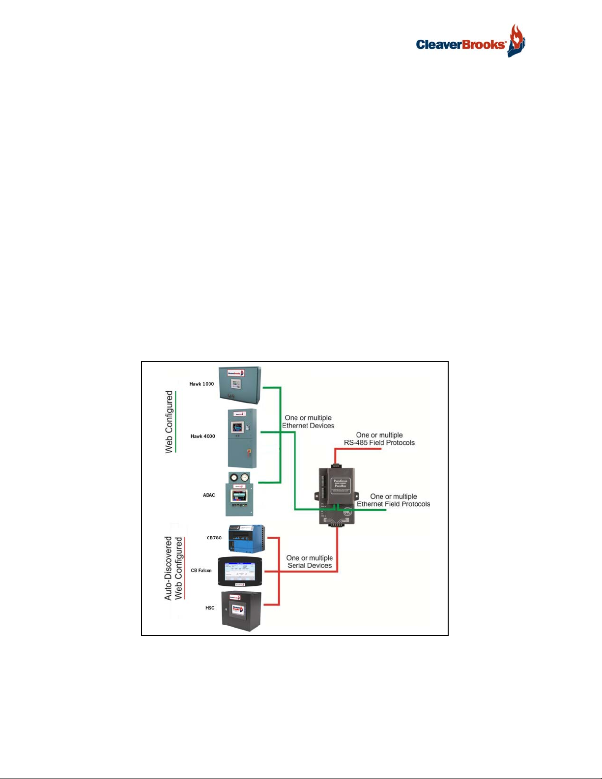
ProtoNode is an external, high performance Building Automation multi-protocol gateway that is configured to automatically communicate between any of Cleaver-Brooks' products (hereafter called
“device”) to various building automation protocols. These protocols include BACnet® MS/TP, BACnet/IP, Metasys® N2 by JCI, Modbus TCP/IP, Modbus RTU, Ethernet/IP and LonWorks®.
It is not necessary to download any configuration files to support the required applications. The ProtoNode is pre-loaded with tested Profiles/Configurations for the supported devices.
We use 2 methods to dynamically configure the ProtoNode to support the devices with the selected
protocol.
Auto-Discovery: Supported RS-485 devices can be automatically detected and identified for addition
to the ProtoNode's configuration. (Section 1.2)
Web Configurator: Ethernet devices connected to the ProtoNode can not be Auto-Discovered. To add
Ethernet devices to the gateway, profiles must be selected in the ProtoNode's Web Configurator. The
Web Configurator shows all the stored profiles/devices on the ProtoNode. It will also show all the RS485 devices that were previously discovered. After selecting the device, the Modbus Node-ID and,
only for Ethernet Devices, the IP Address must also be entered. Once all the devices are selected and
saved, the ProtoNode automatically builds and downloads the configuration for the desired protocol.
ProtoNode Applications
1
BACnet is a registered trademark of ASHRAE
2
Metasys is a registered trademark of Johnson Controls Inc.
3
LonWorks is a registered trademark of Echelon Corporation
8 750-426
Page 11

ProtoNode Gateway
1.2 Methods of Configuration - Cleaver-Brooks' Devices
The ProtoNode offers two methods of configuration:
• Auto-Discovery for RS-485 devices listed below in Figure 1.
• Web Configurator for Ethernet devices and RS-485 devices that cannot be identified by Auto-Discovery
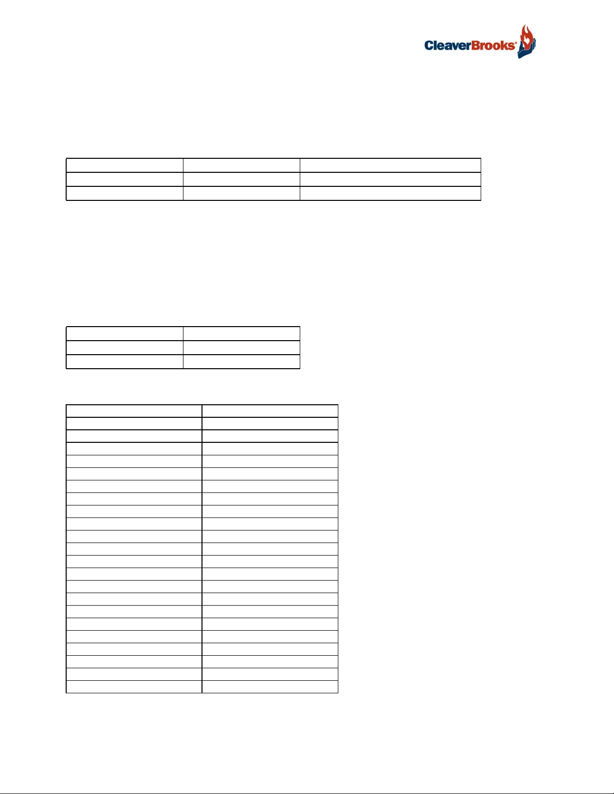
A list of C-B products for use with the ProtoNode, together with their respective means of configuration, is shown in the table below.
Devices Type of Communication Type of Configuration
Falcon Hydronic RS-485 Auto-Discovery/Web Configurator
Falcon Steam RS-485 Auto-Discovery/Web Configurator
CB780 RS-485 Web Configurator
CB120 RS-485 Web Configurator
HSC Admin RS-485 Auto-Discovery/Web Configurator
HSC BIM RS-485 Web Configurator
HSC PIM RS-485 Web Configurator
LCS RS-485 Web Configurator
PCS RS-485 Web Configurator
HAWK 1000 Ethernet Web Configurator
HAWK 2000 Ethernet Web Configurator
HAWK 4000 Ethernet Web Configurator
HAWK 4500 Ethernet Web Configurator
HAWK 5000 Ethernet Web Configurator
HAWK Master Ethernet Web Configurator
HAWK ADAC Ethernet Web Configurator
HAWK ICS Ethernet Web Configurator
Shark 100 Ethernet Web Configurator
Shark 200 Ethernet Web Configurator
UDC2500 Ethernet Web Configurator
HSC Pump Interface (PIM) Ethernet Web Configurator
HSC Boiler Interface (BIM) Ethernet Web Configurator
CB780 CB783 FARC Ethernet Web Configurator
HAWK 4000 V2 Ethernet Web Configurator
ADAC 1000 Ethernet Web Configurator
FIGURE 1 - Method of configuration for the devices
750-426 9
Page 12
ProtoNode Gateway
2. PROTONODE SETUP
2.1 Record Identification Data
Each ProtoNode has a unique part number located on the underside of the unit. This number should
be recorded, as it may be required for technical support. The numbers are as follows:
Model Part Number Description
ProtoNode RER 833-06022-000 BACnet, N2, Modbus, Ethernet/IP
ProtoNode LER 833-06029-000 LonWorks
FIGURE 2 - ProtoNode Part Numbers
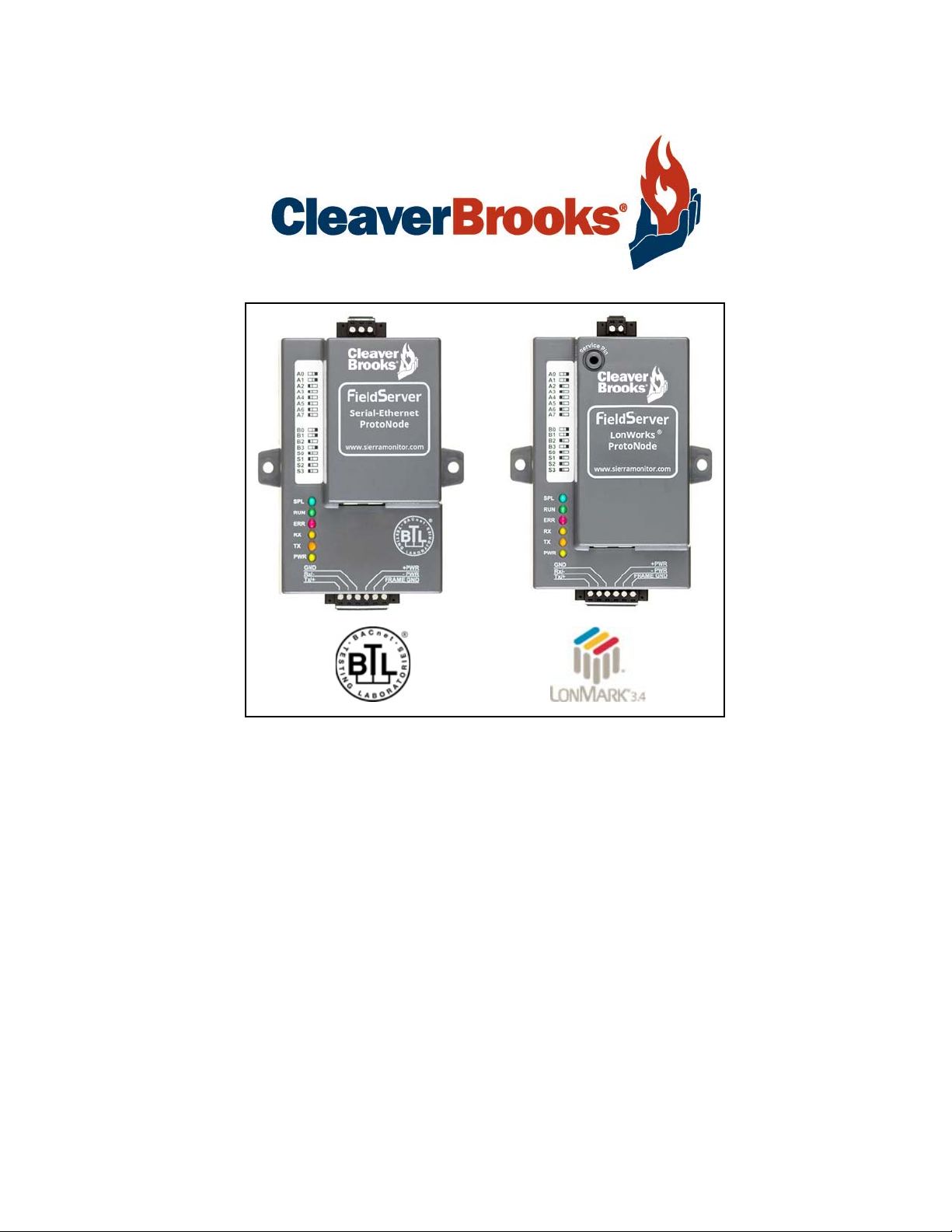
• RER units have the following 3 ports: RS-485 + Ethernet + RS-485
• LER units have the following 3 ports: LonWorks + Ethernet + RS-485
2.2 Point Count Capacity and Registers per Device
The total number of Modbus registers presented by all of the devices attached to the ProtoNode
cannot exceed:
Model Total Registers
ProtoNode RER 10,000
ProtoNode LER 5,000
FIGURE 3 - Supported Point Count Capacity
DEVICE REGISTERS PER DEVICE
Falcon_Hydronic 92
Falcon_Steam 62
CB780 93
CB120 94
HSC 318
LCS 59
PCS 57
HAWK_1000 278
HAWK_2000 75
HAWK_4000 293
HAWK_5000 278
HAWK_Master 200
HAWK_ADAC 275
HAWK_ICS 146
Shark100 41
Shark200 50
UDC2500 42
HSC_Pump_Interface 47
HSC_Boiler_Interface 40
CB780_CB783_FARC 178
Hawk_4000_V2 378
ADAC_1000 338
FIGURE 4 - Modbus Registers per Device
10 750-426
Page 13

ProtoNode Gateway
2.3 Configuring Device Communications
2.3.1 Input COM Setting s on all Seria l De vice s C onnect ed to the Pro to Node
All of the connected serial devices MUST have the same Baud Rate, Data Bits, Stop Bits, and Parity settings as the ProtoNode.
Figure 5 specifies the device serial port settings required to communicate with the ProtoNode.
Port Setting Falcon Steam & Hydronic
Protocol Modbus RTU Modbus RTU
Baud Rate 38400 9600
Parity None None
Data Bits 8 8
Stop Bits 1 1
FIGURE 5 - COM Settings
2.3.2 Set Modbus Node-ID for each device attached to the ProtoNode
Other Serial Devices
Set Modbus Node-ID for each of the devices attached to ProtoNode. The Modbus Node-ID's need to
be uniquely assigned between 1 and 255. The Modbus Node-ID that is assigned for each device
needs to be documented. The Modbus Node-IDs assigned are used for designating the Device
Instance for BACnet/IP and BACnet MS/TP (Section 2.5.2)
The Metasys N2 and Modbus TCP/IP Field Protocol Node-IDs are automatically set to the same
value as the Node-ID of the device.
2.3.3 Set IP Address for each Ethernet Device Connected to the ProtoNode
Ensure devices are set to Modbus TCP/IP to communicate with the ProtoNode.
• The device needs to be on the same IP subnet as the ProtoNode and the configuration PC.
• Record the following device information to start the setup:
IP Address
IP port
Node-ID
NOTE: This information is required for Section 4.
2.4 Selecting the Desired Field Protocol
NOTE: If using the ProtoNode only for cloud-based data monitoring, Sections 2.4 and 2.5 may be
skipped.
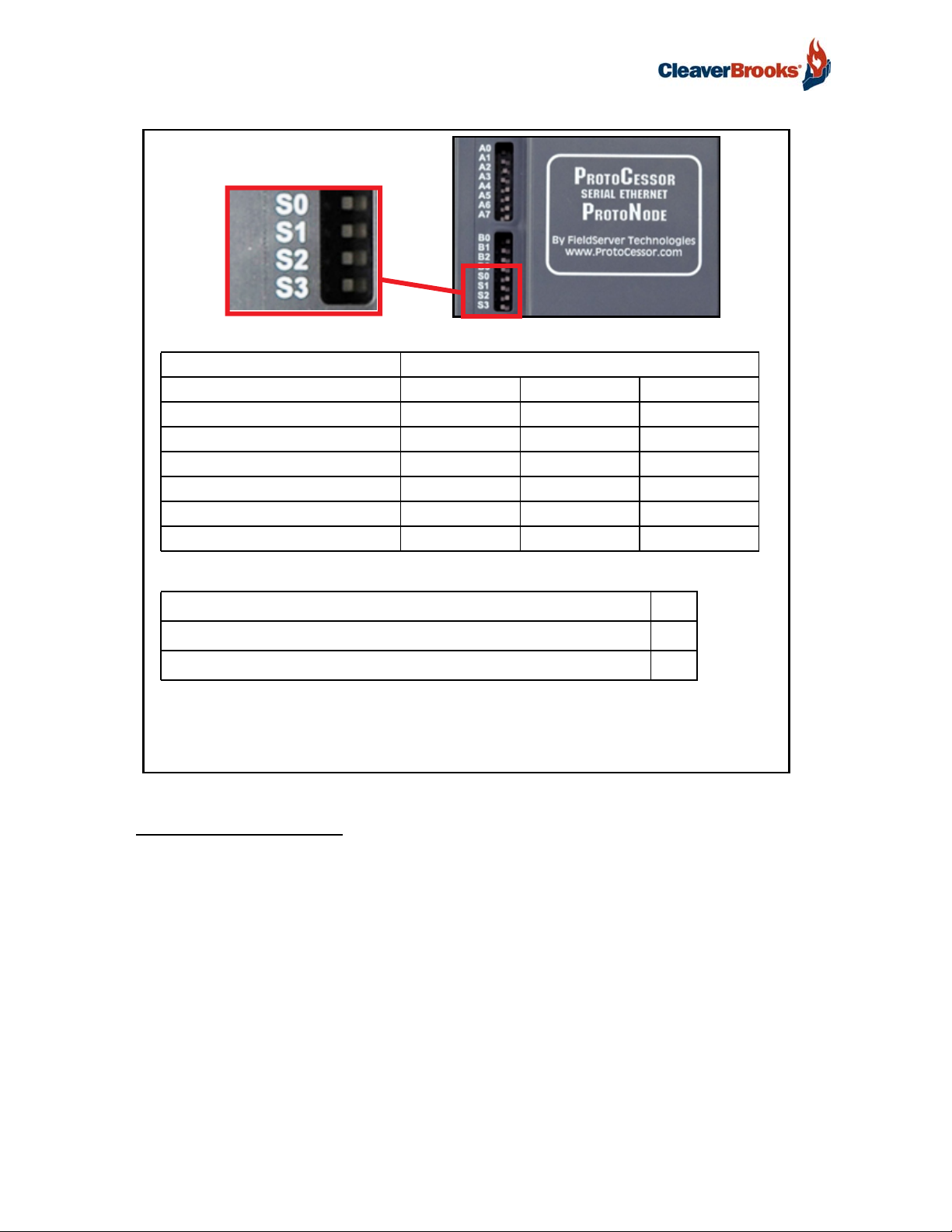
• ProtoNode RER units use the “S” bank of DIP switches (S0 - S2) to select the Field Protocol.
See Figure 6 for the DIP switch settings.
The OFF position is when the DIP switches are set closest to the outside of the box.
• ProtoNode LER units do not use the “S” bank DIP switches to select a Field Protocol. On ProtoNode LER
units, these DIP switches are disabled; the Field Protocol is always LonWorks.
750-426 11
Page 14
ProtoNode Gateway
ProtoNode RER S Bank DIP Switches
Profile S0 S1 S2
BACnet IP Off Off Off
BACnet MSTP On Off Off
Metasys N2 Off On Off
Modbus TCP & Modbus RTU On On Off
Ethernet/IP Off Off On
BACnet MS/TP (single node) On Off On
S Bank DIP Switches
S3 DIP Switch Auto-Discovery Mode S3
Auto-Discovery ON - Build New Configuration On
Auto-Discover OFF - Save Current Configuration Off
NOTE: When setting DIP switches, ensure that power to the board is OFF.
FIGURE 6 - S Bank DIP Switches
2.4.1 Enabling Auto-Discovery
The S3 DIP switch is used to both enable Auto-Discovery of known devices attached to the ProtoNode, and to save the recently discovered configuration.
See the table in Figure 6 for the DIP switch setting to enable Auto-Discovery.
If the ProtoNode is being installed for the first time, set S3 to the ON position to enable Auto-Discovery.
The ON position is when the DIP switches are set closest to the inside of the box.
12 750-426
Page 15
ProtoNode Gateway
2.5 BMS Network Settings: MAC Address, Device Instance and Baud Rate
2.5.1 BACnet MS/TP (RER): Setting the MAC Address for BMS Network
Only 1 MAC address is set for the ProtoNode regardless of how many devices are connected.
Set the BACnet MS/TP MAC addresses of the ProtoNode to a value between 1 to 127 (MAC Master
Addresses); this is so that the BMS Front End can find the ProtoNode via BACnet auto discovery.
Note: Never set a BACnet MS/TP MAC Address from 128 to 255. Addresses from 128 to 255 are
Slave Addresses and can not be discovered by BMS Front Ends that support auto discovery of BACnet MS/TP devices.
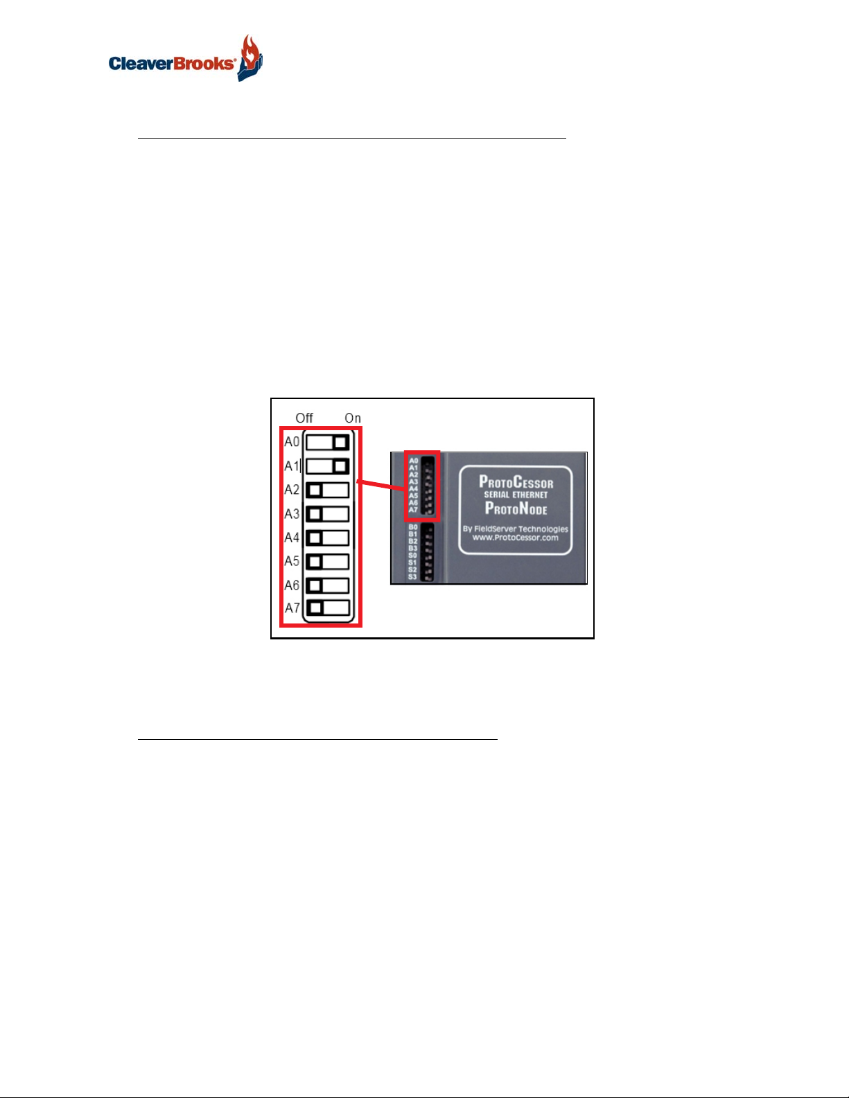
Set “A” bank DIP switches A0 - A7 to assign a MAC Address to the ProtoNode for BACnet MS/TP.
Please refer to Appendix C for the complete range of MAC Addresses and DIP switch settings.
NOTE: When using Metasys N2 and Modbus TCP/IP, the A Bank of DIP switches are disabled
and not used. They should be set to OFF.
FIGURE 7 - MAC Address DIP Switches
NOTE: When setting DIP Switches, please ensure that power to the board is OFF.
2.5.2 BACnet (RER): Calculating the Default Device Instance
The Device Instance value is automatically generated using the following formula:
BACnet Device Instance = (Device Node ID) + (Default Node Offset)
NOTE: The default Node Offset is 50,000.
For example, if Device A has a Node ID of 1 and Device B has a Node ID of 2, then:
BACnet Device Instance A = (1) + (50000) = 50001
BACnet Device Instance B = (2) + (50000) = 50002
NOTE: The Node ID is set in Section 2.3.2.
To reach a specific BACnet Device Instance result, refer to Section 5.
750-426 13
Page 16
ProtoNode Gateway
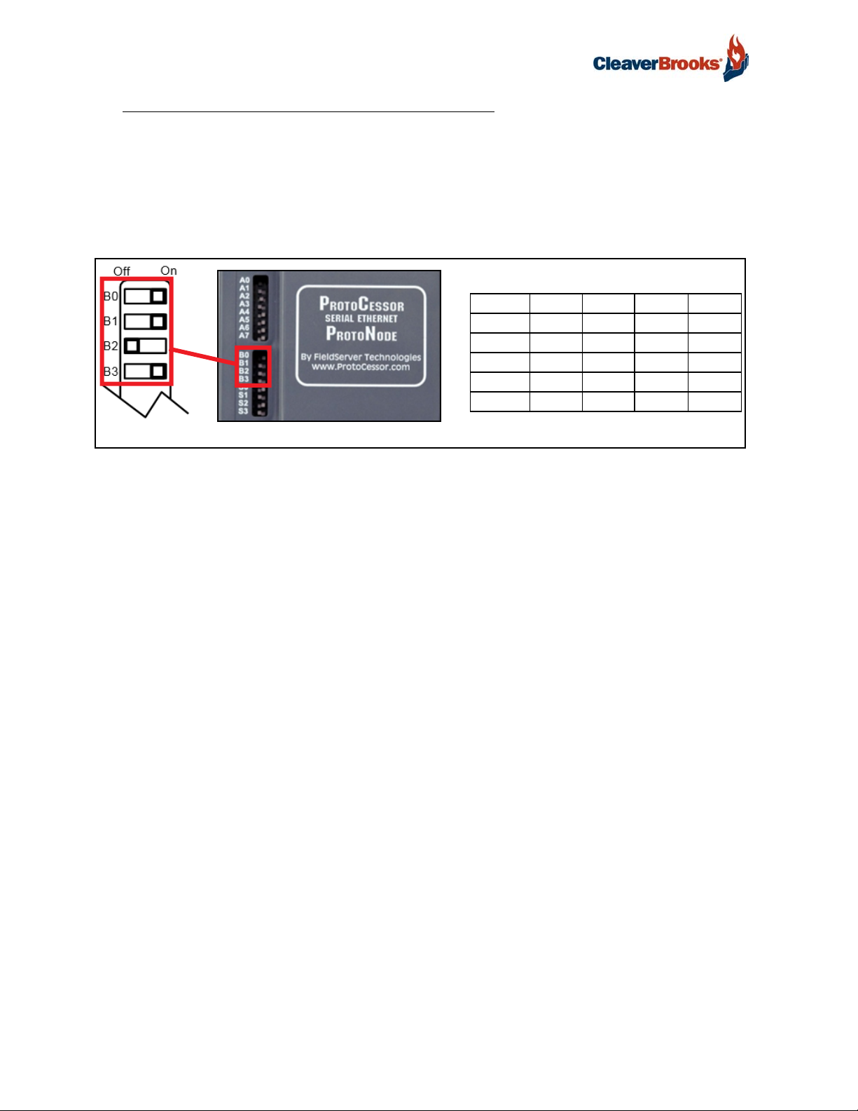
2.5.3 BACnet MS/TP: Setting the Baud Rate for BMS Network
DIP switches B0 – B3 can be used to set the field baud rate of the ProtoNode to match the baud
rate required by the BMS for BACnet MS/TP.
The ProtoNode baud rate for Metasys N2 is set for 9600. DIP switches B0 – B3 are disabled for
Metasys N2 on ProtoNode RER.
DIP switches B0 – B3 are disabled on ProtoNode LER (LonWorks).
Table 1: Baud Rate DIP Switch Selection
Baud B0 B1 B2 B3
9600 On On On Off
19200 Off Off Off On
38400* On On Off On
57600 Off Off On On
76800 On Off On On
Baud Rate DIP Switches
*Factory default
FIGURE 8 - Baud Rate DIP Switches
NOTE: When setting DIP switches, ensure that power to the board is OFF.
14 750-426
Page 17
3. INTERFACING PROTONODE TO DEVICES
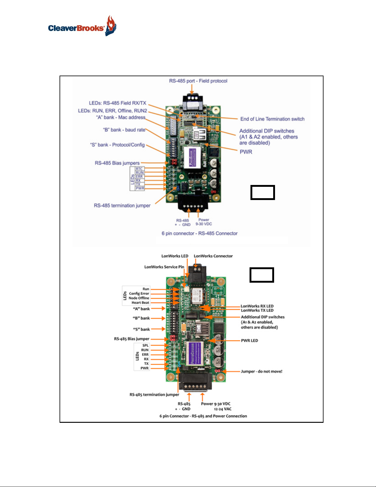
3.1 ProtoNode Connection Ports
ProtoNode Gateway
RER
FIGURE 9 - ProtoNode
LER
Connection Ports
750-426 15
Page 18
ProtoNode Gateway
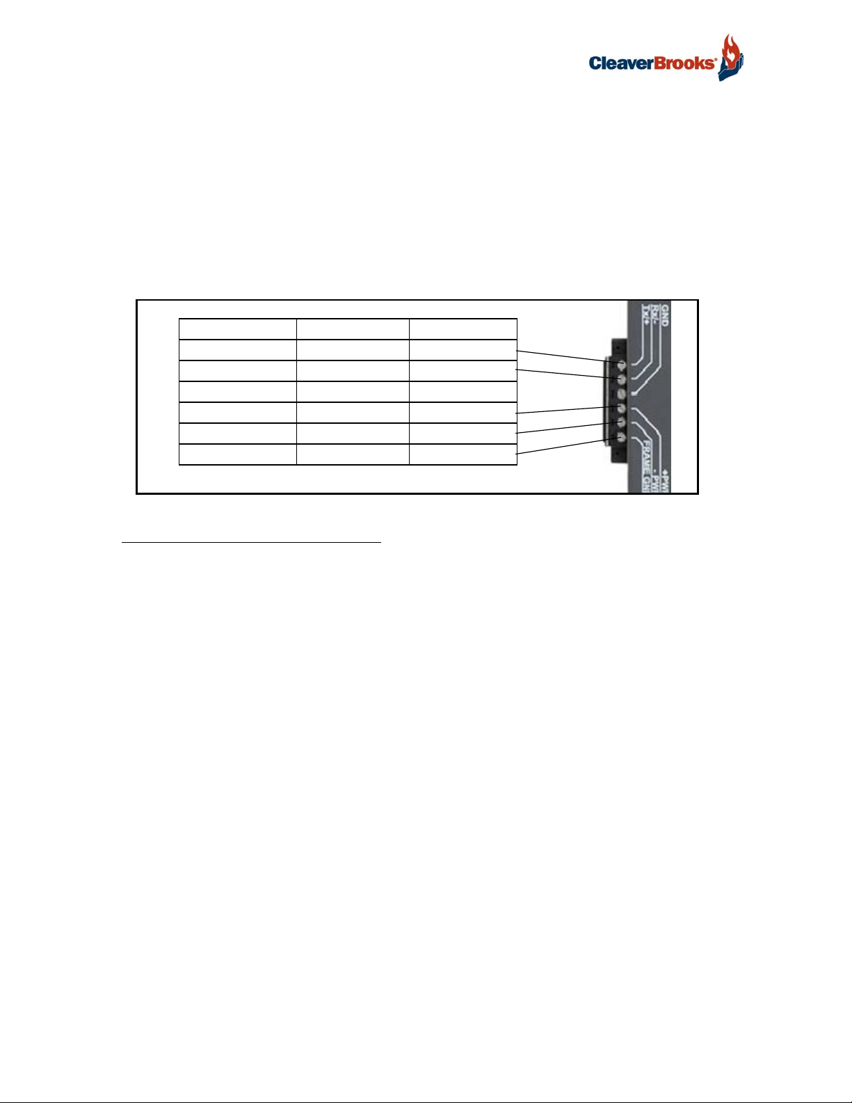
3.2 Device Connections to ProtoNode
ProtoNode 6 Pin Phoenix connector for RS-485 Devices
The 6 pin Phoenix connector is the same for ProtoNode RER (BACnet) and LER (LonWorks).
Pins 1 through 3 are for Modbus RS-485 devices. The RS-485 GND (Pin 3) is not typically connected.
Pins 4 through 6 are for power. Do not connect power (wait until Section 3.6).
Device Pins ProtoNode Pin # Pin assignment
Pin RS-485 + Pin 1 RS-485 +
Pin RS-485 - Pin 2 RS-485 -
Pin GND Pin 3 RS-485 GND
Power In (+) Pin 4 V +
Power In (-) Pin 5 V -
Frame Ground Pin 6 FRAME GND
FIGURE 10 - RS-485 and Power Connections
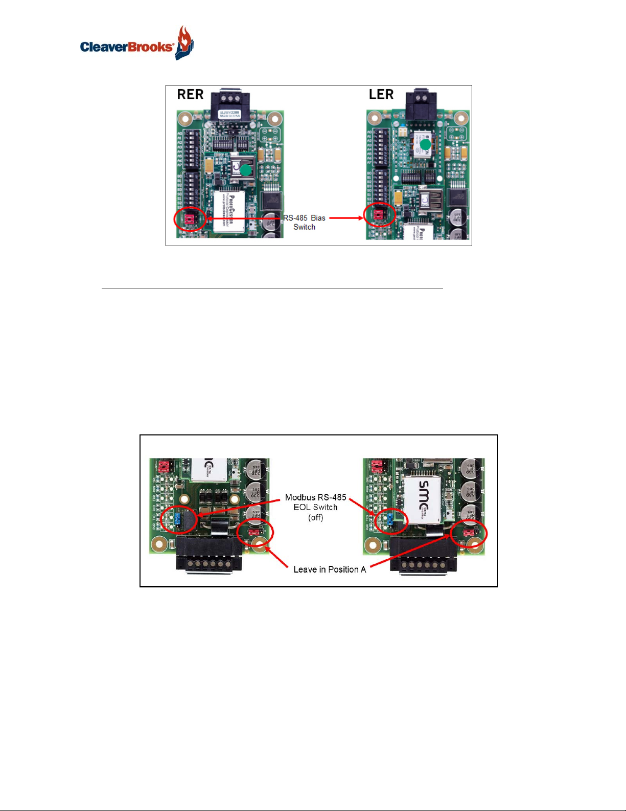
3.2.1 Biasing the Modbus RS-485 Network
An RS-485 network with more than one device needs to have biasing to ensure proper communication. The biasing only needs to be done on one device.
The ProtoNode has 510 Ohm resistors that can be used to set the biasing. The ProtoNode's default
positions from the factory for the biasing jumpers are OFF.
The OFF position is when the 2 RED biasing jumpers straddle the 4 pins closest to the outside of the
board of the ProtoNode. See Figure 11.
Only turn biasing ON:
• IF the BMS cannot see more than one device connected to the ProtoNode
• AND all the settings (Modbus COM settings, wiring, and DIP switches) have been checked.
To turn biasing ON, move the 2 RED biasing jumpers to straddle the 4 pins closest to the inside of
the board of the ProtoNode.
16 750-426
Page 19
ProtoNode Gateway
(off)
FIGURE 11 - RS-485 Bias Switch
3.2.2 End of Line Termination Switch for the Modbus RS-485 Device Network
On long RS-485 cabling runs, the RS-485 trunk must be properly terminated at each end.
The ProtoNode has an End Of Line (EOL) blue jumper. The default setting for this Blue EOL switch is
OFF with the jumper straddling the pins closest to the inside of the board of the ProtoNode.
On short cabling runs the EOL switch does not to need to be turned ON.
If the ProtoNode is placed at one of the ends of the trunk, set the blue EOL jumper to the ON position straddling the pins closest to the outside of the board of the ProtoNode.
Always leave the single Red Jumper in the A position (default factory setting).
RER
FIGURE 12 - RS-485 EOL Termination Switch
LER
750-426 17
Page 20
ProtoNode Gateway
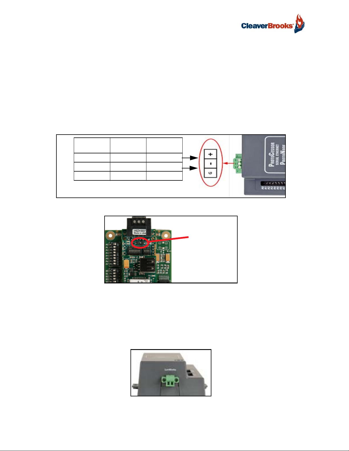
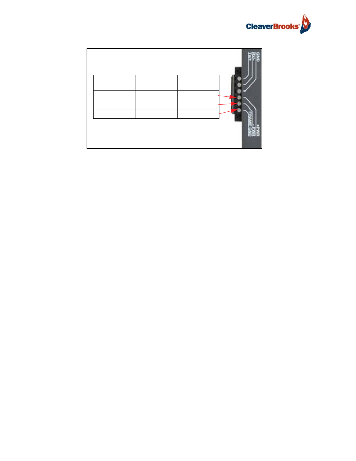
3.3 BACnet MS/TP or Metasys N2 (RER): Wiring Field Port to RS-485 Network
Connect the BACnet MS/TP or Metasys N2 RS-485 network wires to the 3-pin RS-485 connector on ProtoNode RER as shown below.
• Use standard grounding principles for RS-485 GND.
See Section 4.4 for information on connecting to BACnet/IP network.
If the ProtoNode is the last device on the BACnet MS/TP or Metasys N2 trunk, then the End-Of-Line
Termination Switch needs to be enabled (Figure 14).
• The default setting from the factory is OFF (switch position = right side).
• To enable the EOL Termination, turn the EOL switch ON (switch position = left side).
BMS RS-485
Wiring
RS-485 + Pin 1 RS-485 +
RS-485 - Pin 2 RS-485 -
- Pin 3 RS-485 GND
ProtoNode
Pin #
Pin
Assignment
FIGURE 13 - Connection from ProtoNode to RS-485 Field Network
End-of-Line Switch
FIGURE 14 - RS-485 BMS Network EOL Switch
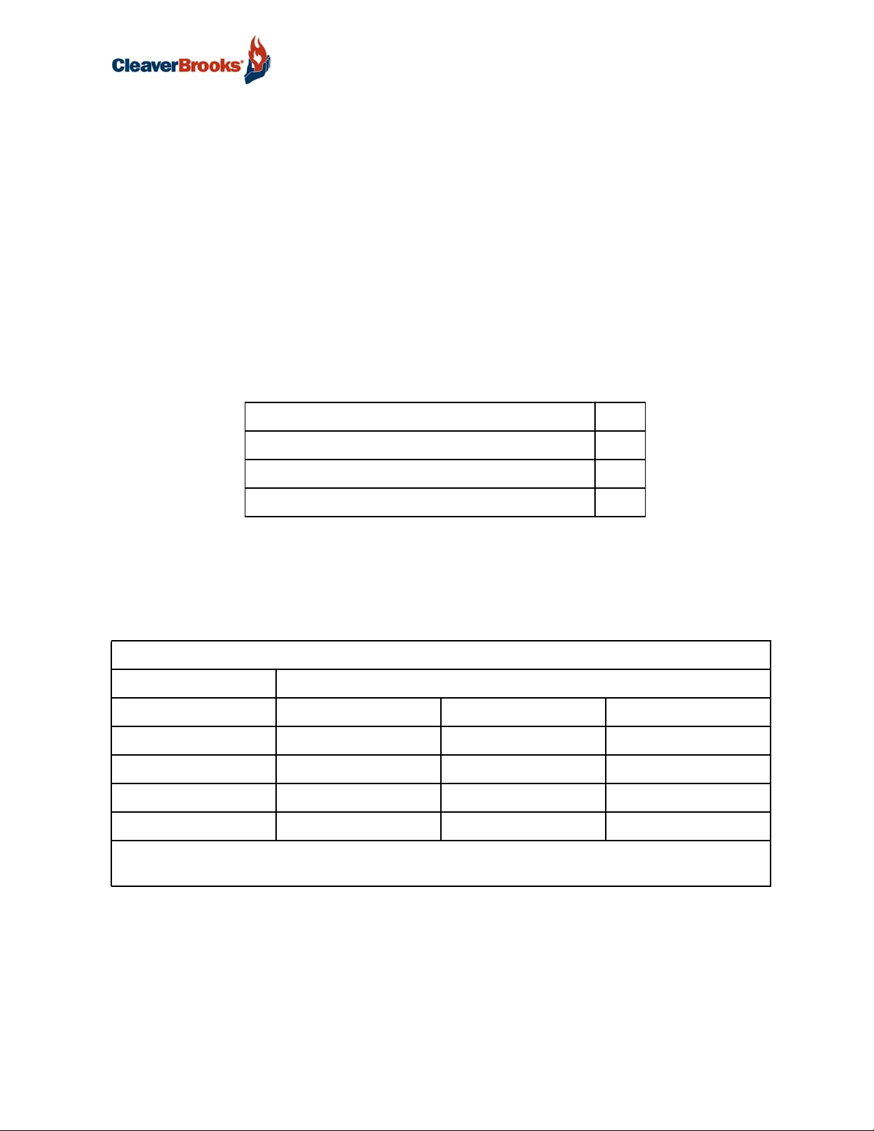
3.4 LonWorks (LER): Wiring LonWorks Devices to the LonWorks Terminal
Wire the LonWorks device network to the ProtoNode LonWorks Terminal.
• Use approved cable per the FT-10 installation guidelines
• LonWorks has no polarity.
FIGURE 15 - LonWorks Terminal
18 750-426
Page 21
ProtoNode Gateway
3.5 Auto-Discovery: After Completion - Turn Off to Save Configuration
NOTE: If Modbus TCP/IP was selected for the field/BMS protocol, skip this section. Auto-Discovery
is NOT used for Modbus TCP/IP.
The S3 DIP Switch for Enabling Auto-Discovery should have been set in Section 2.4.1 before applying power to the ProtoNode. Do not Enable Auto-Discovery when the unit is powered.
When power is applied to a ProtoNode that is set to enable Auto-Discovery, it will take about 3 minutes to complete the discovery of all of the RS-485 devices attached to the ProtoNode.
• The “TX” LED will flash during Auto-Discovery
• Once Auto-Discovery is complete, the “TX” and “RX” LEDs should flash rapidly, indicating good communication between discovered devices
• Once the ProtoNode has discovered all of the RS-485 devices, set the S3 DIP switch to the OFF position
to save the current configuration.
ProtoNode RER and LER
S3 DIP Switch Auto-Discovery Mode S3
Auto-Discovery ON - Build New Configuration On
Auto-Discover OFF - Save Current Configuration Off
FIGURE 16 - S3 DIP Switch setting for Auto Discovering Devices
3.6 Power-Up ProtoNode
Check power requirements in the table below:
Power Requirement for ProtoNode at 9V through 30 VDC or 12-24 VAC
Current Draw Type
ProtoNode Family 12VDC/VAC 24VDC/VAC 30VDC
RER (Typical) 170mA 100mA 80mA
RER (Maximum) 240mA 140mA 100mA
LER (Typical) 210mA 130mA 90mA
LER (Maximum) 250mA 170mA 110mA
Note: These values are 'nominal' and a safety margin should be added to the power supply of the host system. A safety margin of 25% is recommended.
FIGURE 17 - Required current draw for the ProtoNode
Apply power to ProtoNode as shown below in Figure 18. Ensure that the power supply used complies
with the specifications provided in Appendix E.1.
• ProtoNode accepts either 9-30VDC or 12-24 VAC on pins 4 and 5.
• Frame GND should be connected.
750-426 19
Page 22
ProtoNode Gateway
Power to
ProtoNode
Power In (+) Pin 4 V +
Power In (-) Pin 5 V -
Frame Ground Pin 6 FRAME GND
ProtoNode
Pin #
Pin
Assignment
FIGURE 18 - Power Connections
20 750-426
Page 23
ProtoNode Gateway
4. WEB CONFIGURATOR
Use Protonode's Web Configurator to set up the gateway.
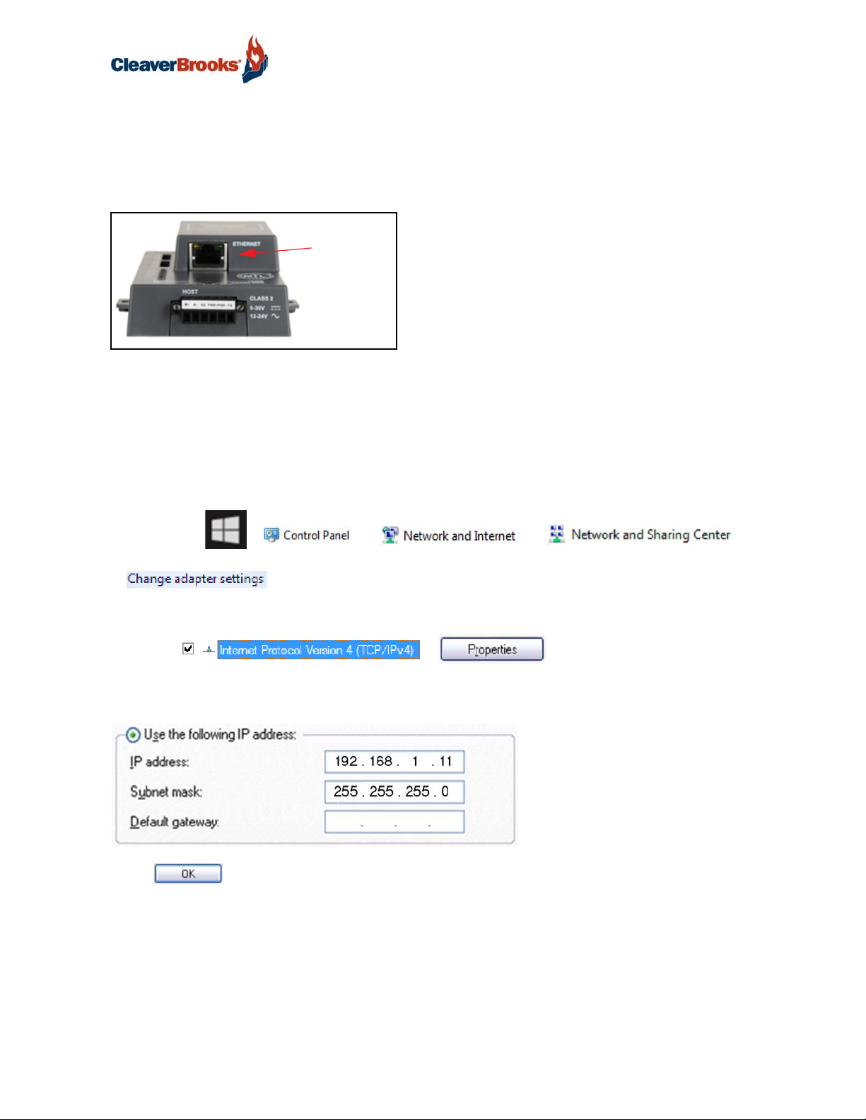
4.1 Connect the PC to ProtoNode via the Ethernet Port
Ethernet
port
FIGURE 19 - Ethernet Port
• Connect a standard CAT5 Ethernet cable (Straight through or Cross-Over) between the PC and ProtoNode.
• The Default IP Address of ProtoNode is 192.168.1.24, Subnet Mask is 255.255.255.0. If the PC and
ProtoNode are on different IP Networks, assign a static IP Address to the PC on the 192.168.1.xxx network.
• For Windows 10:
Right click on > > >
>
Right-click on Local Area Connection > Properties
Highlight >
Use the following IP Address:
Click twice.
750-426 21
Page 24

ProtoNode Gateway
4.2 Connecting to ProtoNode's Web Configurator
After setting a local PC on the same subnet as the ProtoNode (Section 4.1), open a web browser on
the PC and enter the IP Address of the ProtoNode; the default address is 192.168.1.24.
NOTE: If the IP Address of the ProtoNode has been changed by previous configuration, the
assigned IP Address can be discovered using the FS Toolbox utility. See Appendix A.1 for instructions.
• Once at the Web App splash page, click the <Login> button.
FIGURE 20 - Web App Splash Page
• Enter the previously set up or default user name and password.
NOTE: The default user name is “admin”. The default password is “admin”.
FIGURE 21 - Login Window
22 750-426
Page 25
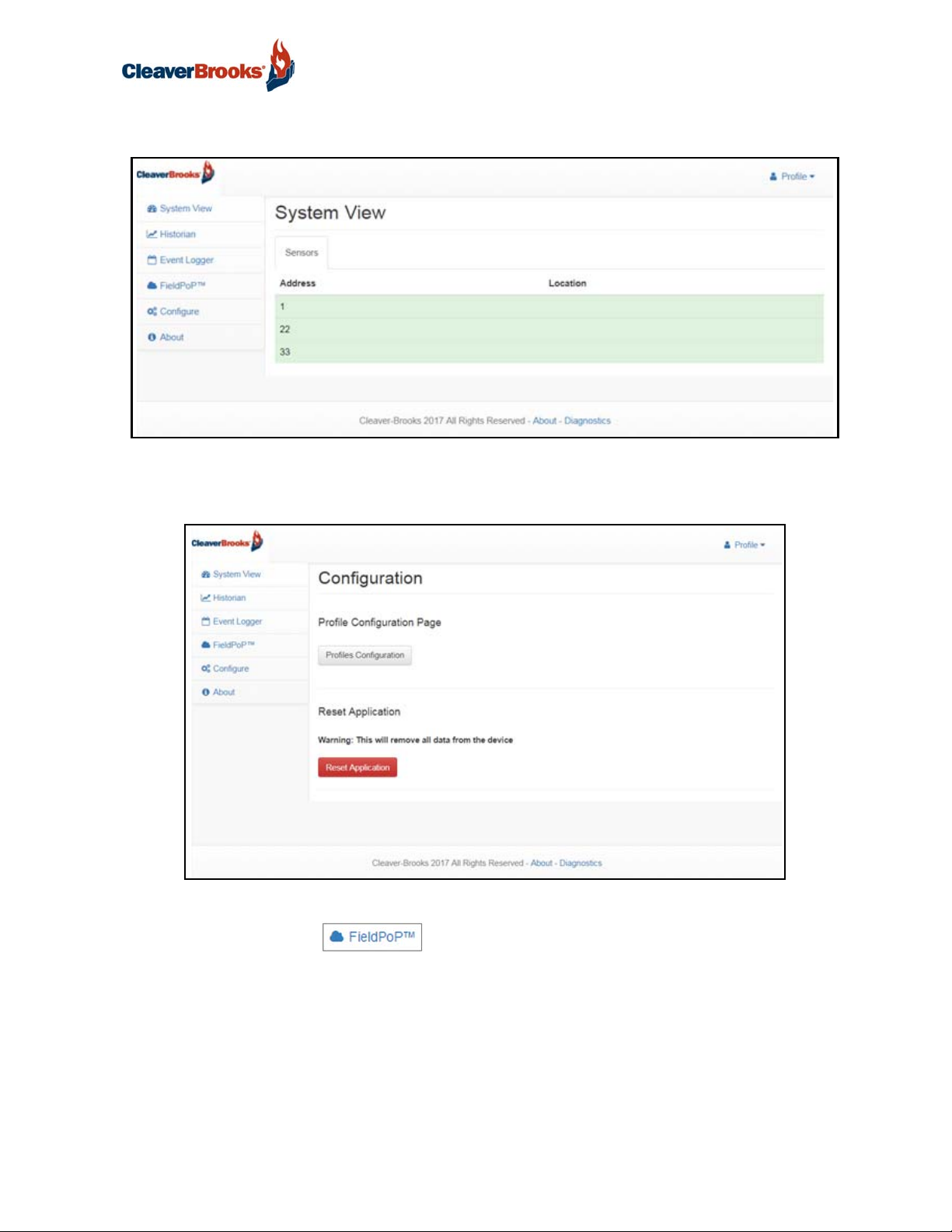
• From the Web App landing page (Figure 22), click the Configure tab.
FIGURE 22 - Web App Landing Page
• Then click the <Profiles Configuration> button to go to the Web Configurator page.
ProtoNode Gateway
FIGURE 23 - Configuration Page
NOTE: The FieldPoP™ tab (see Figure 23) allows users to connect to the SMC Cloud,
Sierra Monitor's device cloud solution for IIoT. The SMC Cloud enables secure remote connection to
field devices through a FieldServer and its local applications for configuration, management, maintenance. For more information about the SMC Cloud, refer to the SMC Cloud Start-up Guide.
NOTE: For Web App instructions to the System View, Historian and Event Logger functions, see the
SMC Cloud Start-up Guide.
750-426 23
Page 26
ProtoNode Gateway
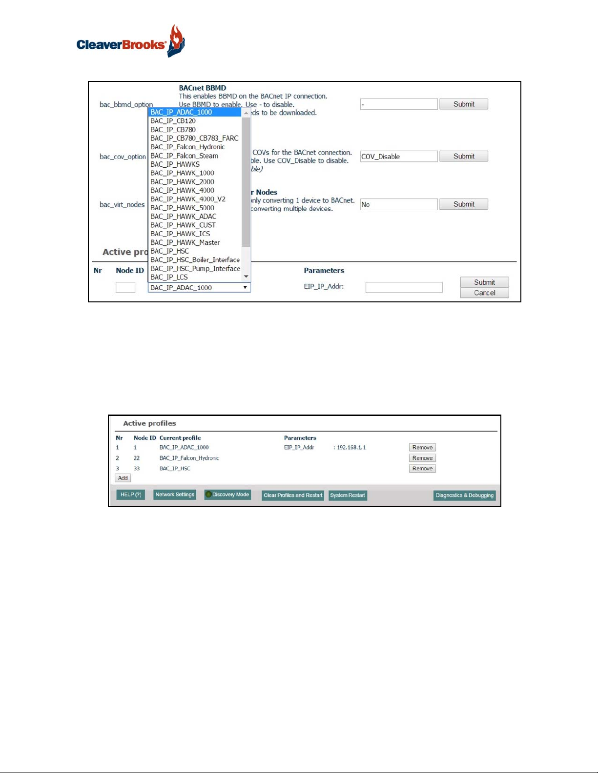
4.3 Selecting Profiles for Devices Connected to ProtoNode
In the Web Configurator, the Active Profiles section is shown on the lower left side of the screen.
The Active Profiles section lists the currently active device profiles, including previous Web Configurator additions and any devices identified by Auto-Discovery configuration methods. This list will be
empty for new installations, or after clearing all configurations.
FIGURE 24 - Web Configurator Showing no Active Profiles
To add an active profile to support a device, click the <Add> button under Active Profiles. This will
present a drop-down box underneath the Current Profile column that lists all the available profiles.
For every device that is added, assign a unique Modbus Node-ID. This specification must match the
device's network settings.
NOTE: If multiple devices are connected to the ProtoNode, set the BACnet Virtual Server Nodes
field to “Yes”; otherwise leave the field on the default “No” setting.
Once the Profile for the device has been selected from the drop-down list, enter the value of the
device's Node-ID which was assigned in Section 2.3.2
24 750-426
Page 27
ProtoNode Gateway
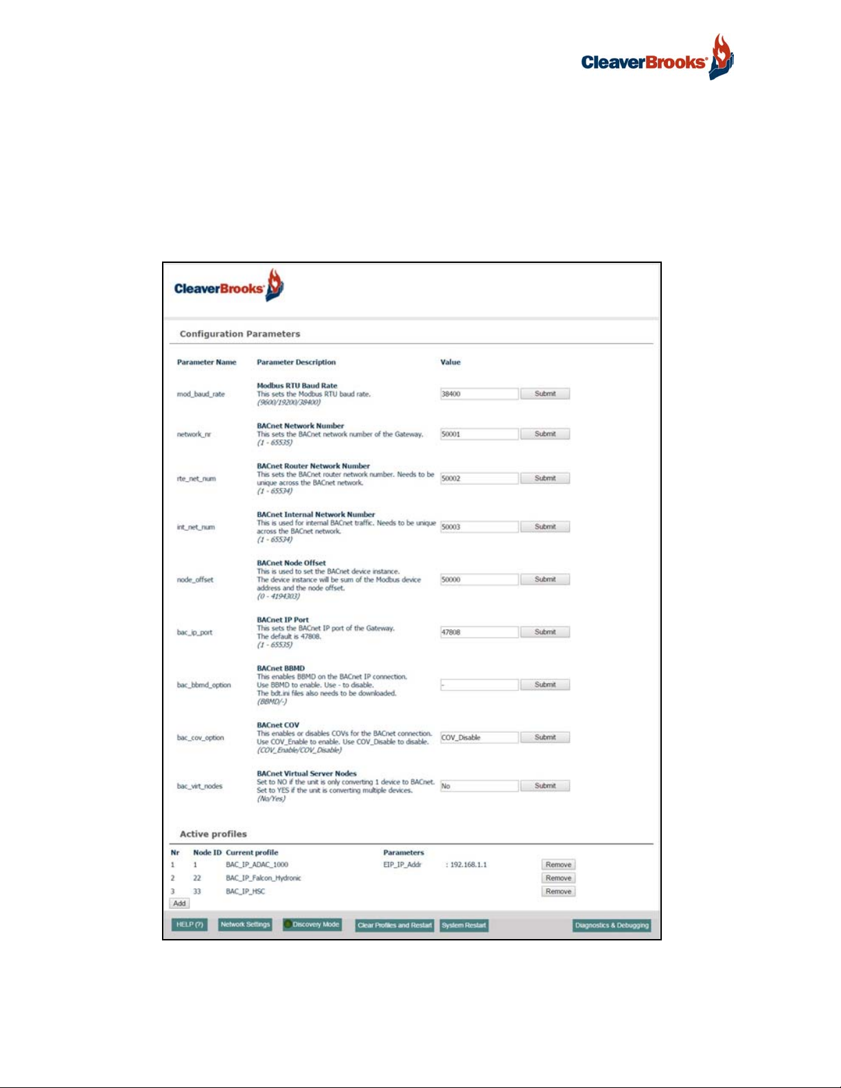
FIGURE 25 - Web Configurator
• Then press the <Submit> button to add the profile to the list of devices to be configured.
• Repeat this process until all the devices have been added.
• Completed additions will be listed under Active Profiles as shown in Figure 26.
• After adding profiles press <System Restart>
FIGURE 26 - Web Configurator Showing Active Profile Additions
showing available profiles for selection
NOTE: If the device is connected via EtherNet/IP, the “IP_Addr” under the Parameters heading
must be gathered from settings on the device. This corresponds to the device IP Address (Section
2.3.3).
750-426 25
Page 28
ProtoNode Gateway
4.4 BACnet/IP and Modbus TCP/IP: Setting IP Address for Field Network
After setting a local PC to the same subnet as the ProtoNode (Section 5.1), open a web browser on
the PC and enter the IP Address of the ProtoNode; the default address is 192.168.1.24.
The Web Configurator is displayed as the landing page (Figure 27).
To access the FieldServer Graphic User Interface (FS-GUI), click on the “Diagnostics & Debugging”
button in the bottom right corner of the page.
FIGURE 27 - Web Configurator Screen with Active Profiles
26 750-426
Page 29
ProtoNode Gateway
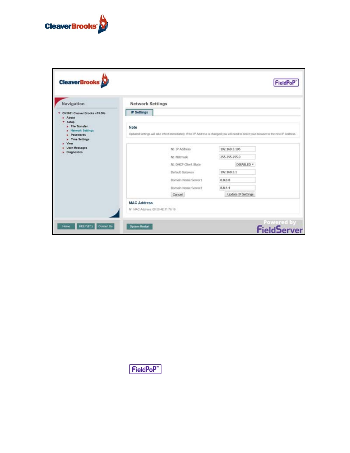
From the FS-GUI landing page, click on “Setup” to expand the navigation tree and then select “Network
Settings” to access the IP Settings menu.
FIGURE 28 - Changing IP Address via FS-GUI
Modify the IP Address (N1 IP Address field) of the ProtoNode Ethernet port.
If necessary, change the Netmask (N1 Netmask field).
If necessary, change the IP Gateway (Default Gateway field).
DHCP Client State should remain disabled; Domain Name Server 1 and 2 should be left at their current values.
NOTE: If the ProtoNode is connected to a managed switch/router, the IP Gateway of the ProtoNode
should be set to the IP Address of that managed switch/router.
Click the “System Restart” button at the bottom of the page to apply changes and restart the ProtoNode.
Unplug Ethernet cable from PC and connect it to the network switch or router.
Record the IP Address assigned to the ProtoNode for future reference.
NOTE: The FieldPoP™ button (see Figure 28) allows users to connect to the SMC
Cloud, Sierra Monitor's device cloud solution for IIoT. The SMC Cloud enables secure remote connection to field devices through a FieldServer and its local applications for configuration, management, maintenance. For more information about the SMC Cloud, refer to the SMC Cloud Start-up
Guide.
750-426 27
Page 30
ProtoNode Gateway
5. BACNET MS/TP AND BACNET/IP: SETTING NODE OFFSET TO ASSIGN SPECIFIC
DEVICE INSTANCES
After setting a local PC to the same subnet as the ProtoNode (Section 4.1), open a web browser on
the PC and enter the IP Address of the ProtoNode; the default address is 192.168.1.24.
• If the IP Address of the ProtoNode has been changed by previous configuration, the assigned IP Address
will need to be obtained from the network administrator.
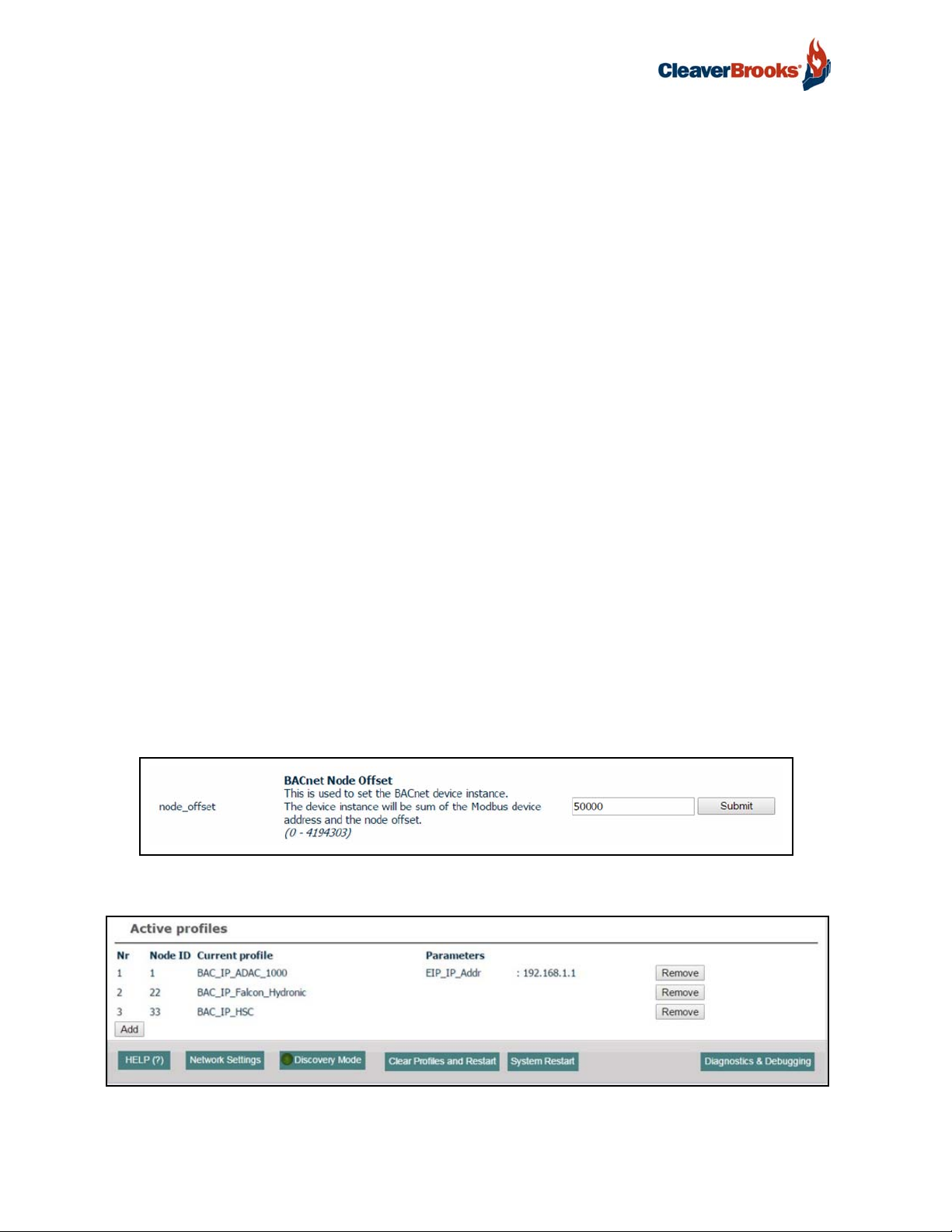
• The Web Configurator will be displayed as the landing page.
Node_Offset field will be presented displaying the current value (default = 50,000). The values
allowed for a BACnet Device Instance can range from 1 to 4,194,303.
• To assign a specific Device Instance (or range); change the Node_Offset value as needed using the calculation below:
Device Instance (desired) = Node_Offset + Modbus Node_ID
For example, if the desired Device Instance for the device 1 is 50,001 and the following is true:
Device 1 has a Modbus Node-ID of 1
Device 2 has a Modbus Node-ID of 22
Device 3 has a Modbus Node-ID of 33
Then plug the device 1's information into the formula to find the desired Node_Offset:
50,001 = Node_Offset + 1
50,000 = Node_Offset
Once the Node_Offset value is input, it will be applied to all devices as shown below:
Device 1 Instance will then be = 1,000 + Node_ID = 1,000 + 1 = 1,001
Device 2 Instance will then be = 1,000 + Node_ID = 1,000 + 22 = 1,022
Device 3 Instance will then be = 1,000 + Node_ID = 1,000 + 33 = 1,033
Click “Submit” once the desired value is entered.
FIGURE 29 - Web Configurator Node Offset Field
FIGURE 30 - Active Profiles
28 750-426
Page 31

ProtoNode Gateway
6. HOW TO START THE INSTALLATION OVER: CLEARING PROFILES
• After setting your PC to be on the same subnet as the ProtoNode (section 4.1), open a web browser on
your PC and enter the IP address of the ProtoNode; the default address is 192.168.1.24.
• If the IP address of the ProtoNode has been changed by previous configuration, you will need to get the
assigned IP address from the network administrator.
• The Web Configurator will be displayed as your landing page.
• At the bottom-left of the page, click the “Clear Profiles and Restart” button.
• Once restart is complete, all the past profiles that were discovered and or added via the Web configurator
will be delete. The unit is now ready to be reinstalled.
750-426 29
Page 32

ProtoNode Gateway
7. COMMISSIONING THE PROTONODE ON A LONWORKS NETWORK
Commissioning may only be performed by the LonWorks administrator.
The User will be prompted by the LonWorks Administrator to hit the Service Pin on the ProtoNode
LER at the correct step of the Commissioning process, which is different for each LonWorks Network
Management Tool.
If an XIF file is required, see 7.1 below.
FIGURE 31 - LonWorks Service Pin
7.1 Downloading an XIF File
• Connect a CAT5 Ethernet cable (straight through or crossover) between the PC and the ProtoNode.
• The Default IP Address of the ProtoNode is 192.168.1.24, Subnet Mask is 255.255.255.0. If the PC and
ProtoNode are on different IP Networks, assign a static IP Address to the PC on the 192.168.1.xxx network.
• For Windows 10:
Right click on > > >
>
Right-click on Local Area Connection > Properties
Highlight >
Use the following IP Address:
Click twice.
30 750-426
Page 33

ProtoNode Gateway
• Open a web browser and go to the following address: [IP Address of ProtoNode]/fserver.xif.
Example: 192.168.1.24/fserver.xif
• If the web browser prompts to save the file, save the file onto the local PC. If the web browser displays the
xif file as a web page, save the file onto the local PC as “fserver.xif”.
FIGURE 32 - Generating an XIF File
750-426 31
Page 34

ProtoNode Gateway
8. SMC CLOUD USER SETUP, REGISTRATION AND LOGIN
8.1 User Setup
When configuring the ProtoNode, the startup technician will prepare an account for the individual
who will be the Enterprise Customer Administrator for the site (see SMC Cloud Startup Guide 750431 for OEM and Enterprise Customer user hierarchy). When configuration is complete, the ProtoNode should be disconnected from the installer’s computer and connected to the company network.
The Administrator should complete the registration process using an on-site computer with network
access.
The Administrator invitee should receive a “Welcome to FieldPoP” email as shown below.
FIGURE 33 - Welcome to FieldPoP Email
NOTE: If no SMC Cloud email was received, check the spam/junk folder for an email from notification@fieldpop.io. Contact the manufacturer's support team if the email cannot be found.
32 750-426
Page 35

Click the “Complete Registration” button and fill in user details accordingly.
FIGURE 34 - Setting User Details
ProtoNode Gateway
• Fill in the name, phone number and password fields.
• Click <Save> to save the user details.
• Record the email account and password for future use.
8.2 Registration Process
Once SMC Cloud user credentials have been generated, the ProtoNode can be registered onto the
SMC Cloud server.
Click on the FieldPoP™ tab on the left-hand side of the screen.
FIGURE 35 - Web App Landing Page - FieldPoP Tab
750-426 33
Page 36

ProtoNode Gateway
The following informational splash page will appear; click <Close> to view the registration page.
FIGURE 36 - Registration Information Page
If a warning message appears instead of the splash page, follow the suggestion presented. If the ProtoNode cannot reach the SMC Cloud server, the following message will appear:
FIGURE 37 - SMC Cloud Connection Problems Message
Follow the directions presented in the warning message and check that the DNS settings are set up
with the following Domain Name Server (DNS) settings:
DNS1=8.8.8.8
DNS2=8.8.4.4
Ensure that the ProtoNode is properly connected to the Internet
NOTE: If changes to the network settings are done, remember to click “Update IP Settings” and
then power cycle the ProtoNode.
34 750-426
Page 37

ProtoNode Gateway
On the registration page, fill in user credentials and all other device information fields for registration
of each individual ProtoNode in the field. The Username and Password are the same as those on the
user’s FieldPoP account.
FIGURE 38 - SMC Cloud Registration Page
To input the device location do one of the following:
• Enter the address in the address field
• Click the <Get Current Location> button to auto-populate. NOTE: This button will only work if location
services have been enabled on the local browser. If using the Chrome browser and connected via LAN,
this method will not work.
• Drop a location directly on the Google map
• Enter the latitude and longitude manually
Click <Register Device>. Once the device has successfully been registered, the following screen will
appear listing the device details and additional information auto-populated by the ProtoNode.
750-426 35
Page 38

ProtoNode Gateway
8.3 Login
FIGURE 39 - Device Registered for SMC Cloud
After the ProtoNode is registered, go to www.fieldpop.io and type in the appropriate login information
as per registration credentials.
FIGURE 40 - SMC Cloud Login Page
If the login password is lost, see the SMC Cloud Start-up Guide for recovery instructions.
36 750-426
Page 39
ProtoNode Gateway
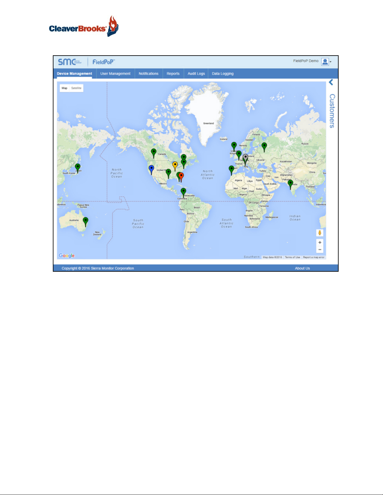
FIGURE 41 - SMC Cloud Landing Page
NOTE: For additional SMC Cloud instructions see the SMC Cloud Start-up Guide.
750-426 37
Page 40

ProtoNode Gateway
APPENDIX A. TROUBLESHOOTING
A.1. Lost or Incorrect IP Address
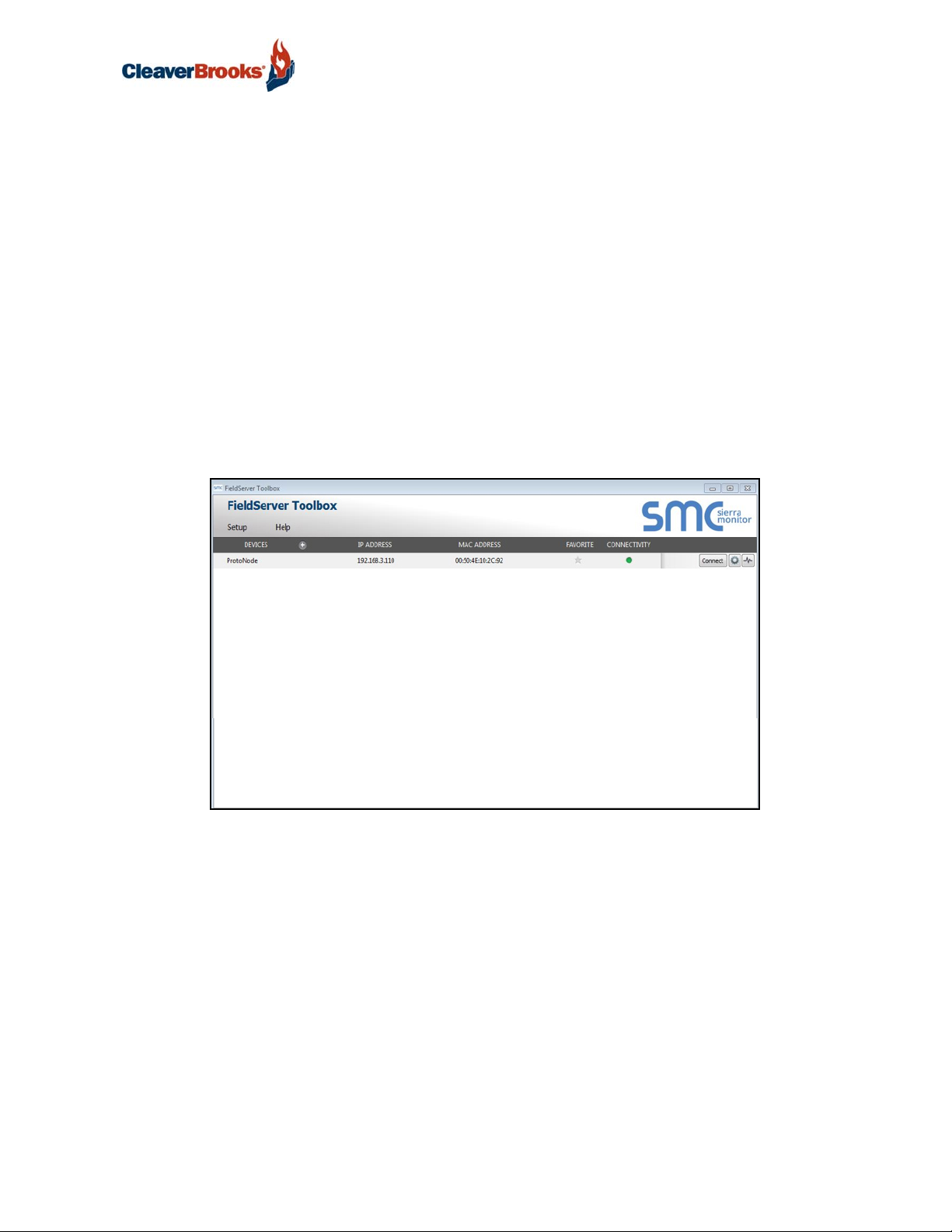
Ensure that FieldServer Toolbox is loaded onto the local PC. Otherwise, download the FieldServerToolbox.zip via the Sierra Monitor Resource Center Software Downloads.
Extract the executable file and complete the installation.
FIGURE 42 - Ethernet port location
Connect a standard CAT5 Ethernet cable between the user's PC and ProtoNode.
Double click on the FS Toolbox Utility and click Discover Now on the splash page.
Check for the IP Address of the desired gateway.
If correcting the IP Address of the gateway: click the settings icon on the same row as the gateway, then click Network Settings, change the IP Address and click Update IP Settings to save.
38 750-426
Page 41

ProtoNode Gateway
A.2. Viewing Diagnostic information
Type the IP address of the ProtoNode into your web browser or use the FieldServer Toolbox to connect to the ProtoNode.
Click on Diagnostics and Debugging button, then click on view, and then on connections.
If there are any errors showing on the Connection page, please refer to Appendix A.3 for the relevant
wiring and settings.
FIGURE 43 - Error messages screen
750-426 39
Page 42
ProtoNode Gateway
A.3. Check Wiring and Settings
• No COMS on Modbus RTU side: If Tx/Rx are not flashing rapidly then there is a COM issue on the Modbus
side. Check the following:
LEDs on ProtoNode. (Appendix A.4)
Check baud rate, parity, data bits, stop bits
Check Modbus device address
Verify wiring
Verify the Modbus device is connected to the same subnet as the ProtoNode
Verify the Modbus device was discovered in Web Configurator. (Section 4)
• Field COM problems:
If Ethernet protocols are used, observe Ethernet LEDs on the ProtoNode (Appendix A.4)
Check dipswitch settings (using correct baud rate and device instance)
Verify IP Address setting
Verify wiring
If the problem persists, a Diagnostic Capture needs to be taken and sent to Support. (Appendix A.5).
750-426 40
Page 43
ProtoNode Gateway
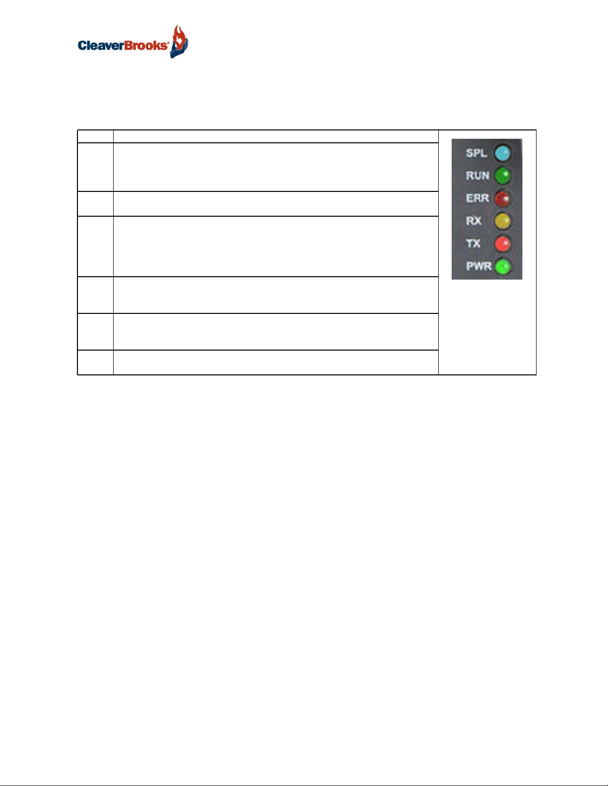
A.4. LED Diagnostics for Communications Between ProtoNode and Devices
See the diagram below for ProtoNode RER and LER LED Locations.
Table 2:
Tag Description
SPL The SPL LED will light if the unit is not getting a response from one or
more of the configured devices.
For LonWorks units, LED will light until the unit is commissioned on the
LonWorks network.
RUN The RUN LED will start flashing 20 seconds after power indicating normal
operation.
ERR The SYS ERR LED will go on solid 15 seconds after power up. It will turn
off after 5 seconds. A steady red light will indicate there is a system error
on ProtoNode. If this occurs, immediately report the related “system error”
shown in the error screen of the GUI interface to Sierra Monitor Corporation for evaluation.
RX The RX LED will flash when a message is received on the serial port on the
6-pin connector.
If the serial port is not used, this LED is non-operational.
TX The TX LED will flash when a message is sent on the serial port on the 6-
pin connector.
If the serial port is not used, this LED is non-operational.
PWR This is the power light and should show steady green at all times when
unit is powered.
750-426 41
Page 44

ProtoNode Gateway
A.5. Take Diagnostic Capture with the FieldServer Toolbox
Once the Diagnostic Capture is complete, email it to a customer service representative (found by visiting www.cleaverbrooks.com/Find-a-Rep/Index.aspx). The Diagnostic Capture will accelerate diagnosis of the problem.
Ensure that FieldServer Toolbox is loaded onto the local PC. Otherwise, download FieldServer-Toolbox.zip via the Sierra Monitor Resource Center Software Downloads.
Extract the executable file and complete the installation.
FIGURE 44 - Ethernet Port Location
Connect a standard Cat 5 Ethernet cable between the PC and ProtoNode.
Double click on the FS Toolbox Utility
• Step 1: Take a Log
Click on the diagnose icon of the desired device.
• Ensure “Full Diagnostic” is selected. This is the default value, and should be used unless instructed otherwise by C-B tech support.
42 750-426
Page 45

• Click on <Start Diagnostic>
ProtoNode Gateway
• When the capture period is finished, the “Diagnostic Test Complete” window will appear
• Step 2: Send Log
Once the Diagnostic test is complete, a .zip file will be saved on the PC.
• Choose <Open> to launch explorer and have it point directly at the correct folder.
• Send the Diagnostic zip file to customer service representative (found by visiting www.cleaverbrooks.com/
Find-a-Rep/Index.aspx)
A.6. Mounting ProtoNode
The following mounting options are available:
• Product comes with tabs for wall or surface mount. These can be snapped off if not required.
• DIN rail mounting bracket - ordered separately.
FIGURE 45 - DIN Rail
NOTE: Install only as instructed, failure to follow the installation guidelines or using screws without the DIN Rail Mounting Bracket could result in permanent damage to the product.
750-426 43
Page 46

ProtoNode Gateway
A.7. Update Firmware
To load a new version of the firmware, follow these instructions:
1. Extract and save the new file onto the local PC.
2. Open a web browser and type the IP Address of the FieldServer in the address bar.
Default IP Address is 192.168.1.24
Use the FS Toolbox utility if the IP Address is unknown (Appendix A.1)
3. Click on the "Diagnostics & Debugging" button.
4. In the Navigation Tree on the left hand side, do the following:
a. Click on “Setup”
b. Click on “File Transfer”
c. Click on the “General” tab
5. In the General tab, click on “Choose Files” and select the web.img file extracted in step 1.
6. Click on the orange “Submit” button.
7. When the download is complete, click on the “System Restart” button.
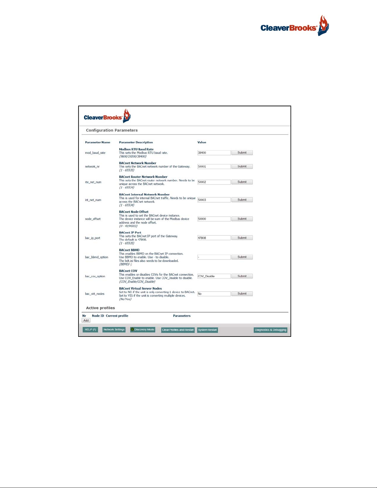
A.8. BACnet: Setting Network_Number for more than one ProtoNode on Subnet
For both BACnet MS/TP and BACnet/IP, if more than one ProtoNode is connected to the same subnet,
they must be assigned unique Network_Number values.
On the main Web Configuration screen, update the BACnet Network Number field and click submit.
The default value is 50001.
FIGURE 46 - Web Configurator - Network Number Field
44 750-426
Page 47

ProtoNode Gateway
A.9. Securing ProtoNode with Passwords
Access to the ProtoNode can be restricted by enabling a password. There are 2 access levels defined by 2
account names: Admin and User.
• The Admin account has unrestricted access to the ProtoNode.
• The User account can view any ProtoNode information, but cannot make any changes or restart the ProtoNode.
The password needs to be a minimum of eight characters and is case sensitive.
If the password is lost, click cancel on the password authentication popup window, and email the password recovery token to a customer service representative (found by visiting www.cleaverbrooks.com/Finda-Rep/Index.aspx) to receive a temporary password from the support team.
Access the ProtoNode to set a new password.
FIGURE 47 - FS-GUI Passwords Page
FIGURE 48 - Password Recovery Page
750-426 45
Page 48

ProtoNode Gateway
APPENDIX B — DATA POINT MAPPINGS for CLEAVER-BROOKS APPLICATIONS
B.1. FALCON HYDRONIC
FALCON HYDRONIC Modbus RTU Mappings to BACnet MS/TP, BACnet/IP, Metasys N2, Modbus and LonWorks
RER LER
BACnet
Point Name
PumpC BI 3 DI 3 30003 2 CFC_AB_XXX[0].2 nvoPumpC_XXX SNVT_switch
Blower_Mtr BI 4 DI 4 30003 3 CFC_AB_XXX[0].3 nvoBlwr_Mtr_XXX SNVT_switch
Ext_Ignition BI 5 DI 5 30003 4 CFC_AB_XXX[0].4 nvoExt_Ign_XXX SNVT_switch
Pilot-MainDBI_Valve BI 6 DI 6 30003 5 CFC_AB_XXX[0].5 nvoPlMnDBIVl_XXX SNVT_switch
Main_Valve BI 7 DI 7 30003 6 CFC_AB_XXX[0].6 nvoMainValve_XXX SNVT_switch
Alarm BI 8 DI 8 30003 7 CFC_AB_XXX[0].7 nvoAlarm_XXX SNVT_switch
Interlock BI 9 DI 9 30003 8 CFC_AB_XXX[0].8 nvoInterlock_XXX SNVT_switch
PreIgn_Interlock BI 10 DI 10 30003 9 CFC_AB_XXX[0].9 nvoPreIgnInt_XXX SNVT_switch
Load_Control_In BI 11 DI 11 30003 10 CFC_AB_XXX[0].10 nvoLdCtrlIn_XXX SNVT_switch
Low_Fire_Switch BI 12 DI 12 30003 11 CFC_AB_XXX[0].11 nvoLoFireSw_XXX SNVT_switch
High_Fire_Switch BI 13 DI 13 30003 12 CFC_AB_XXX[0].12 nvoHiFireSw_XXX SNVT_switch
Stat_Demand BI 14 DI 14 30003 13 CFC_AB_XXX[0].13 nvoStatDem_XXX SNVT_switch
TimeOfDay BI 15 DI 15 30003 14 CFC_AB_XXX[0].14 nvoTimeOfDay_XXX SNVT_switch
Safety_Relay BI 16 DI 16 30003 15 CFC_AB_XXX[0].15 nvoSafetyRel_XXX SNVT_switch
Int_Air_Switch BI 17 DI 17 30004 0 CFC_AB_XXX[1].0 nvoIntAirSw_XXX SNVT_switch
Low_Water BI 18 DI 18 30004 1 CFC_AB_XXX[1].1 nvoLoWater_XXX SNVT_switch
Aux_Low_Water BI 19 DI 19 30004 2 CFC_AB_XXX[1].2 nvoAuxLoWtr_XXX SNVT_switch
High_Limit BI 20 DI 20 30004 3 CFC_AB_XXX[1].3 nvoHiLimit_XXX SNVT_switch
High_Gas_Press BI 21 DI 21 30004 4 CFC_AB_XXX[1].4 nvoHiGasPrx_XXX SNVT_switch
Low_Gas_Press BI 22 DI 22 30004 5 CFC_AB_XXX[1].5 nvoLoGasPrx_XXX SNVT_switch
Natural_Gas BI 23 DI 23 30004 6 CFC_AB_XXX[1].6 nvoNatGas_XXX SNVT_switch
Propane_Gas BI 24 DI 24 30004 7 CFC_AB_XXX[1].7 nvoPropanGas_XXX SNVT_switch
DEMAND SOURCE AI 1 AI 1 30007 CFC_AI_XXX[0] nvoDemSrc_XXX SNVT_count_f
OUTLET WATER TEMP DEG F AI 2 AI 2 30008 CFC_AR_XXX[0] nvoOutWtrTmp_XXX SNVT_temp_p
FIRING_RATE AI 3 AI 3 30009 CFC_AI_XXX[1] nvoFirRate_XXX SNVT_count_f
FAN_SPEED AI 4 AI 4 30010 CFC_AI_XXX[2] nvoFanSpeed_XXX SNVT_count_f
FLAME_SIGNAL AI 5 AI 5 30011 CFC_AI_XXX[3] nvoFlameSig_XXX SNVT_count_f
INLET WATER TEMP DEG F AI 6 AI 6 30012 CFC_AR_XXX[1] nvoInlWtrTmp_XXX SNVT_temp_p
DHW WATER TEMP DEG F AI 7 AI 7 30013 CFC_AR_XXX[2] nvoDHWWtrTmp_XXX SNVT_temp_p
HEADER or ODT DEG F AI 8 AI 8 30014 CFC_AR_XXX[3] nvoHdrOrOdt_XXX SNVT_temp_p
STACK TEMP DEG F AI 9 AI 9 30015 CFC_AR_XXX[4] nvoStkTemp_XXX SNVT_temp_p
CH SETPOINT DEG F AI 11 AI 11 30017 CFC_AR_XXX[5] nvoCH_SP_XXX SNVT_temp_p
DHW SETPOINT DEG F AI 12 AI 12 30018 CFC_AR_XXX[6] nvoDHW_SP_XXX SNVT_temp_p
ANALOG_INPUT AI 14 AI 14 30022 CFC_AI_XXX[4] nvoAnaInput_XXX SNVT_count_f
BURN_CTL_STATUS AI 15 AI 15 30033 CFC_AI_XXX[5] nvoBrnCtStat_XXX SNVT_count_f
BURN_CTL_STATE AI 16 AI 16 30034 CFC_AI_XXX[6] nvoBrnCtlSte_XXX SNVT_count_f
LOCKOUT_CODE AI 17 AI 17 30035 CFC_AI_XXX[7] nvoLockoutCd_XXX SNVT_count_f
HOLD_CODE AI 18 AI 18 30041 CFC_AI_XXX[8] nvoHoldCode_XXX SNVT_count_f
CH STATUS AI 20 AI 20 30063 CFC_AI_XXX[9] nvoCH_Status_XXX SNVT_count_f
CH SETPOINT SOURCE AI 21 AI 21 30066 CFC_AI_XXX[10] nvoCH_SPSrc_XXX SNVT_count_f
CH HEAT DEMAND AI 22 AI 22 30067 CFC_AI_XXX[11] nvoCH_HtDem_XXX SNVT_count_f
CH BURNER DEMAND AI 23 AI 23 30068 CFC_AI_XXX[12] nvoCH_BrnDem_XXX SNVT_count_f
CH REQUESTED RATE AI 24 AI 24 30069 CFC_AI_XXX[13] nvoCH_ReqRat_XXX SNVT_count_f
CH FROST HEAT DEMAND AI 25 AI 25 30070 CFC_AI_XXX[14] nvoCH_FrHtDm_XXX SNVT_count_f
CH FROST BURNER DEMAND AI 26 AI 26 30071 CFC_AI_XXX[15] nvoCHFrBrnDm_XXX SNVT_count_f
DHW STATUS AI 29 AI 29 30081 CFC_AI_XXX[16] nvoDHW_Stat_XXX SNVT_count_f
DHW SETPOINT SOURCE AI 30 AI 30 30082 CFC_AI_XXX[17] nvoDHW_SPSrc_XXX SNVT_count_f
BACnet
Data
Type
Object
Id
N2
Data
Type
N2 Point
Address
Modbus
Register
(Bit
EIP Tag Name Lon Name Lon SNVT Type
)
46 750-426
Page 49

ProtoNode Gateway
FALCON HYDRONIC Modbus RTU Mappings to BACnet MS/TP, BACnet/IP, Metasys N2, Modbus and LonWorks (Continued)
RER LER
BACnet
Point Name
DHW HEAT DEMAND AI 32 AI 32 30084 CFC_AI_XXX[18] nvoDHW_HtDem_XXX SNVT_count_f
DHW BURNER DEMAND AI 33 AI 33 30085 CFC_AI_XXX[19] nvoDHW_BrnDm_XXX SNVT_count_f
DHW REQUESTED RATE AI 34 AI 34 30086 CFC_AI_XXX[20] nvoDHW_ReqRt_XXX SNVT_count_f
CH PUMP STATUS AI 39 AI 39 30097 CFC_AI_XXX[21] nvoCH_PmpSt_XXX SNVT_count_f
DHW PUMP STATUS AI 43 AI 43 30101 CFC_AI_XXX[22] nvoDHWPmpSt_XXX SNVT_count_f
SYSTEM PUMP STATUS AI 48 AI 48 30106 CFC_AI_XXX[23] nvoSysPmpSt_XXX SNVT_count_f
BOILER PUMP STATUS AI 51 AI 51 30109 CFC_AI_XXX[24] nvoBlrPmpSt_XXX SNVT_count_f
AUXILIARY1 PUMP STATUS AI 54 AI 54 30112 CFC_AI_XXX[25] nvoAux1PmpSt_XXX SNVT_count_f
AUXILIARY2 PUMP STATUS AI 55 AI 55 30114 CFC_AI_XXX[26] nvoAux2PmpSt_XXX SNVT_count_f
BURNER_ENABLE AI 57 AI 57 30204 CFC_AI_XXX[27] nvoBrnrEnbl_XXX SNVT_count_f
LEAD/LAG SETPOINT DEG F AI 60 AI 60 30547 CFC_AR_XXX[7] nvoLL_SP_XXX SNVT_temp_p
LEAD/LAG_ENABLE AI 61 AI 61 30556 CFC_AI_XXX[28] nvoLL_Enbl_XXX SNVT_count_f
CYCLE_COUNT AI 58 AI 58 30129-30 CFC_AD_XXX[0] nvoCycCount_XXX SNVT_count_f
BURNER RUN_TIME AI 59 AI 59 30131-32 CFC_AD_XXX[1] nvoBrnRunTim_XXX SNVT_time_hour
BOILER BURNER ENABLE AV 1 AO 1 40204 CFC_AWI_XXX[0] nviBrnrEnbl_XXX SNVT_count_f
*
BOILER LEAD/LAG ENABLE AV 11 AO 11 40556 CFC_AWI_XXX[1] nviLL_Enbl_XXX SNVT_count_f
*
BOILER CH SETPOINT DEG F AV 21 AO 21 40212 CFC_AWR_XXX[0] nviCH_SP_XXX SNVT_temp_p
*
BOILER LEAD/LAG SETPOINT DEG F AV 31 AO 31 40547 CFC_AWR_XXX[1] nviLL_SP_XXX SNVT_temp_p
*
OUTLET WATER TEMP DEG C AI 62 AI 62 30008 CFC_AR_XXX[8]
INLET WATER TEMP DEG C AI 66 AI 66 30012 CFC_AR_XXX[9]
DHW WATER TEMP DEG C AI 67 AI 67 30013 CFC_AR_XXX[10]
HEADER or ODT DEG C AI 68 AI 68 30014 CFC_AR_XXX[11]
STACK TEMP DEG C AI 69 AI 69 30015 CFC_AR_XXX[12]
CH SETPOINT DEG C AI 71 AI 71 30017 CFC_AR_XXX[13]
DHW SETPOINT DEG C AI 72 AI 72 30018 CFC_AR_XXX[14]
LEAD/LAG SETPOINT DEG C AI 73 AI 73 30547 CFC_AR_XXX[15]
BOILER CH SETPOINT DEG C AV 41 AO 41 40212 CFC_AWR_XXX[2]
*
BOILER LEAD/LAG SETPOINT DEG C AV 51 AO 51 40547 CFC_AWR_XXX[3]
*
FIRING_RATE_PERCENT AI 74 AI 74 30074 CFC_AI_XXX[29]
4-20Ma Remote Ctl Input AI 75 AI 75 40016 CFC_AI_XXX[30] nvo420mARmCt_XXX SNVT_count_f
Active LL Setpoint AI 76 AI 76 40019 CFC_AI_XXX[31] nvoActLLSP_XXX SNVT_temp_p
Alarm Reason AI 77 AI 77 40036 CFC_AI_XXX[32] nvoAlmRson_XXX SNVT_count_f
Annunciator First Out AI 78 AI 78 40037 CFC_AI_XXX[33] nvoAnn1stOut_XXX SNVT_count_f
Annunciator Hold AI 79 AI 79 40038 CFC_AI_XXX[34] nvoAnnHold_XXX SNVT_count_f
Outdoor Temperature AI 80 AI 80 40171 CFC_AI_XXX[35] nvoOutdrTmp_XXX SNVT_temp_p
CH Pump Cycle Count AV 61 AO 61 40133-34 CFC_AD_XXX[2] nvi/nvoCHPmpCyCt_X XX SNVT_count_f
*
Lead Boiler Address AI 81 AI 81 40802 CFC_AI_XXX[36] nvoLdBlrAddr_XXX SNVT_count_f
Firing Rate Type AI 82 AI 82 30193 CFC_AI_XXX[37] nvoFirRteTyp_XXX SNVT_count_f
Master ID AI 83 AI 83 30546 CFC_AI_XXX[38] nvoMasterID_XXX SNVT_count_f
Slave Setpoint AI 84 AI 84 30030 CFC_AI_XXX[39] nvoSlaveSP_XXX SNVT_temp_p
Master OAT AI 85 AI 85 30171 CFC_AI_XXX[40] nvoMstrOAT_XXX SNVT_temp_p
Max Firing Rate AI 86 AI 86 30194 CFC_AI_XXX[41] nvoMxFirRate_XXX SNVT_count_f
Min Firing Rate AI 87 AI 87 30196 CFC_AI_XXX[42] nvoMnFirRate_XXX SNVT_count_f
BACnet
Data
Type
*Write point
Object
Id
N2
Data
Type
N2 Point
Address
Modbus
Register
(Bit
EIP Tag Name Lon Name Lon SNVT Type
)
750-426 47
Page 50

ProtoNode Gateway
B.2. FALCON STEAM
FALCON STEAM Modbus RTU Mappings to BACnet MS/TP, BACnet/IP, Metasys N2, Modbus and LonWorks
RER LER
BACnet
Point Name
PumpA BI 1 DI 1 30003 0 CFS_AB[0].0 nvoPumpA_XXX SNVT_switch
PumpA BI 1 DI 1 30003 0 CFS_AB_XXX[0].0 nvoPumpA_XXX SNVT_switch
PumpB BI 2 DI 2 30003 1 CFS_AB_XXX[0].1 nvoPumpB_XXX SNVT_switch
PumpC BI 3 DI 3 30003 2 CFS_AB_XXX[0].2 nvoPumpC_XXX SNVT_switch
Blower_Mtr BI 4 DI 4 30003 3 CFS_AB_XXX[0].3 nvoBlwr_Mtr_XXX SNVT_switch
Ext_Ignition BI 5 DI 5 30003 4 CFS_AB_XXX[0].4 nvoExt_Ign_XXX SNVT_switch
Pilot_Valve BI 6 DI 6 30003 5 CFS_AB_XXX[0].5 nvoPilotVlv_XXX SNVT_switch
Main_Valve BI 7 DI 7 30003 6 CFS_AB_XXX[0].6 nvoMainValve_XXX SNVT_switch
Alarm BI 8 DI 8 30003 7 CFS_AB_XXX[0].7 nvoAlarm_XXX SNVT_switch
Interlock BI 9 DI 9 30003 8 CFS_AB_XXX[0].8 nvoInterlock_XXX SNVT_switch
PreIgn_Interlock BI 10 DI 10 30003 9 CFS_AB_XXX[0].9 nvoPreIgnInt_XXX SNVT_switch
Load_Control_In BI 11 DI 11 30003 10 CFS_AB_XXX[0].10 nvoLdCtrlIn_XXX SNVT_switch
Low_Fire_Switch BI 12 DI 12 30003 11 CFS_AB_XXX[0].11 nvoLoFireSw_XXX SNVT_switch
High_Fire_Switch BI 13 DI 13 30003 12 CFS_AB_XXX[0].12 nvoHiFireSw_XXX SNVT_switch
Stat_Demand BI 14 DI 14 30003 13 CFS_AB_XXX[0].13 nvoStatDem_XXX SNVT_switch
TimeOfDay BI 15 DI 15 30003 14 CFS_AB_XXX[0].14 nvoTimeOfDay_XXX SNVT_switch
Safety_Relay BI 16 DI 16 30003 15 CFS_AB_XXX[0].15 nvoSafetyRel_XXX SNVT_switch
Int_Air_Switch BI 17 DI 17 30004 0 CFS_AB_XXX[1].0 nvoIntAirSw_XXX SNVT_switch
Low_Water BI 18 DI 18 30004 1 CFS_AB_XXX[1].1 nvoLoWater_XXX SNVT_switch
Aux_Low_Water BI 19 DI 19 30004 2 CFS_AB_XXX[1].2 nvoAuxLoWtr_XXX SNVT_switch
High_Limit BI 20 DI 20 30004 3 CFS_AB_XXX[1].3 nvoHiLimit_XXX SNVT_switch
High_Gas_Press BI 21 DI 21 30004 4 CFS_AB_XXX[1].4 nvoHiGasPrs_XXX SNVT_switch
Low_Gas_Press BI 22 DI 22 30004 5 CFS_AB_XXX[1].5 nvoLoGasPrs_XXX SNVT_switch
High_Water BI 23 DI 23 30004 6 CFS_AB_XXX[1].6 nvoHigh_Wtr_XXX SNVT_switch
Feed_Water BI 24 DI 24 30004 7 CFS_AB_XXX[1].7 nvoFeed_Wtr_XXX SNVT_switch
DEMAND SOURCE AI 1 AI 1 30007 CFS_AI_XXX[0] nvoDemSrc_XXX SNVT_count_f
FIRING_RATE AI 2 AI 2 30009 CFS_AI_XXX[1] nvoFiringRat_XXX SNVT_count_f
FAN_SPEED AI 3 AI 3 30010 CFS_AI_XXX[2] nvoFanSpeed_XXX SNVT_count_f
FLAME_SIGNAL AI 4 AI 4 30011 CFS_AI_XXX[3] nvoFlameSig_XXX SNVT_count_f
STEAM_PRESSURE AI 5 AI 5 30021 CFS_AI_XXX[4] nvoStmPress_XXX SNVT_count_f
ANALOG_INPUT AI 6 AI 6 30022 CFS_AI_XXX[5] nvoAna_Input_XXX SNVT_count_f
ACTIVE_STEAM_SP AI 7 AI 7 30023 CFS_AI_XXX[6] nvoActStmSP_XXX SNVT_count_f
BURN_CTL_STATUS AI 8 AI 8 30033 CFS_AI_XXX[7] nvoBrnCtStat_XXX SNVT_count_f
BURN_CTL_STATE AI 9 AI 9 30034 CFS_AI_XXX[8] nvoBrnCtlSte_XXX SNVT_count_f
LOCKOUT_CODE AI 10 AI 10 30035 CFS_AI_XXX[9] nvoLockoutCd_XXX SNVT_count_f
HOLD_CODE AI 11 AI 11 30041 CFS_AI_XXX[10] nvoHoldCode_XXX SNVT_count_f
CYCLE_COUNT AI 12 AI 12 30129-
RUN_TIME AI 13 AI 13 30131-
BURNER_ENABLE AI 16 AI 16 30204 CFS_AI_XXX[13] nvoBrnrEnbl_XXX SNVT_count_f
STEAM_PRESSURE_SETPOINT AI 14 AI 14 30221 CFS_AI_XXX[14] nvoStmPrsSP_XXX SNVT_count_f
LEAD/LAG_STEAM_PRESS_SET
POINT
LEAD/LAG_HEADER_STEAM_PRESS AI 17 AI 17 30807 CFS_AI_XXX[16] nvoLLHdStmPr_XXX SNVT_count_f
VESSEL WATER TEMP (Deg C) AI 18 AI 18 30008 CFS_AR_XXX[0] nvoVesWtrTmp_XXX SNVT_temp_p
VESSEL WATER TEMP (Deg F) AI 19 AI 19 30008 CFS_AR_XXX[1]
BURNER ENABLE AV 1 AO 1 40204 CFS_AWI_XXX[0] nviBrnrEnbl_XXX SNVT_count_f
*
STEAM_PRESSURE_SETPOINT AV 21 AO 21 40221 CFS_AWI_XXX[1] nviStmPrsSP_XXX SNVT_count_f
*
BACnet
Data
Type
AI 15 AI 15 30739 CFS_AI_XXX[15] nvoLLStmPrSP_XXX SNVT_count_f
Object
Id
N2
Data
Type
N2
Point
Address
Modbus
Register
30
32
(Bit) EIP Tag Name Lon Name Lon SNVT Type
CFS_AI_XXX[11] nvoCycCount_XXX SNVT_count_f
CFS_AI_XXX[12] nvoRunTime_XXX SNVT_count_f
48 750-426
Page 51

ProtoNode Gateway
FALCON STEAM Modbus RTU Mappings to BACnet MS/TP, BACnet/IP, Metasys N2, Modbus and LonWorks (Continued)
RER LER
BACnet
Point Name
LEAD/LAG_ENABLE AV 11 AO 11 40556 CFS_AWI_XXX[2] nviLL_Enbl_XXX SNVT_count_f
*
LEAD/LAG_SETPOINT AV 31 AO 31 40739 CFS_AWI_XXX[3] nviLL_SP_XXX SNVT_count_f
*
FIRING_RATE_PERCENT AI 20 AI 20 30074 CFC_AI_XXX[17] nvoFirRtPct_XXX SNVT_lev_percent
4-20Ma Remote Ctl Input AI 21 AI 21 40016 CFC_AI_XXX[18] nvo420mARmCt_XX X SNVT_count_f
Active LL Setpoint AI 22 AI 22 40019 CFC_AI_XXX[19] nvoActLLSP_XXX SNVT_temp_p
Alarm Reason AI 23 AI 23 40036 CFC_AI_XXX[20] nvoAlmRson_XXX SNVT_count_f
Annunciator First Out AI 24 AI 24 40037 CFC_AI_XXX[21] nvoAnn1stOut_XXX SNVT_count_f
Annunciator Hold AI 25 AI 25 40038 CFC_AI_XXX[22] nvoAnnHold_XXX SNVT_count_f
Outdoor Temperature AI 26 AI 26 40171 CFC_AI_XXX[23] nvoOutdrTmp_XXX SNVT_temp_p
* CH Pump Cycle Count AV 41 AO 41 40133-
Lead Boiler Address AI 27 AI 27 40802 CFC_AI_XXX[25] nvoLdBlrAddr_XXX SNVT_count_f
Firing Rate Type AI 28 AI 28 30193 CFC_AI_XXX[26] nvoFirRteTyp_XXX SNVT_count_f
Master ID AI 29 AI 29 30546 CFC_AI_XXX[27] nvoMasterID_XXX SNVT_count_f
Slave Setpoint AI 30 AI 30 30030 CFC_AI_XXX[28] nvoSlaveSP_XXX SNVT_temp_p
Master OAT AI 31 AI 31 30171 CFC_AI_XXX[29] nvoMstrOAT_XXX SNVT_temp_p
Max Firing Rate AI 32 AI 32 30194 CFC_AI_XXX[30] nvoMxFirRate_XXX SNVT_count_f
Min Firing Rate AI 33 AI 33 30196 CFC_AI_XXX[31] nvoMnFirRate_XXX SNVT_count_f
BACnet
Data
Type
Object
Id
N2
Data
Type
N2
Point
Address
Modbus
Register
34
(Bit) EIP Tag Name Lon Name Lon SNVT Type
CFC_AI_XXX[24] nvi/nvoCHPmpCyCt_ XXX SNVT_count_f
*Write point
750-426 49
Page 52

ProtoNode Gateway
B.3. CB780
CB780 Modbus RTU Mappings to BACnet MS/TP, BACnet/IP, Metasys N2, Modbus and LonWorks
RER LER
Point Name
BACnet
BC_Initiate BI 1 DI 1 40013 0 CB780_AB[0].0 nvoBCInitiat_XXX SNVT_switch
BC_Standby BI 2 DI 2 40013 1 CB780_AB[0].1 nvoBCStandby_XXX SNVT_switch
BC_Purge BI 3 DI 3 40013 2 CB780_AB[0].2 nvoBCPurge_XXX SNVT_switch
BC_Pilot_Ignition BI 4 DI 4 40013 3 CB780_AB[0].3 nvoBCPlt_Ign_XXX SNVT_switch
BC_Main_Ignition BI 5 DI 5 40013 4 CB780_AB[0].4 nvoBCMainIgn_XXX SNVT_switch
BC_Run_Mode BI 6 DI 6 40013 5 CB780_AB[0].5 nvoBCRunMode_XXX SNVT_switch
BC_Postpurge BI 7 DI 7 40013 6 CB780_AB[0].6 nvoBCPostprg_XXX SNVT_switch
BC_Preignition BI 8 DI 8 40013 7 CB780_AB[0].7 nvoBCPreIgn_XXX SNVT_switch
BC_Alarm_Out BI 9 DI 9 40013 13 CB780_AB[0].13 nvoBCAlmOut_XXX SNVT_switch
BC_Lockout BI 10 DI 10 40013 15 CB780_AB[0].15 nvoBCLockout_XXX SNVT_switch
BC_Fault_Code AI 1 AI 1 40001 CB780_AI[0] nvoBCFltCode_XXX SNVT_count_f
BC_Fault_String_Code AI 2 AI 2 40002 CB780_AI[1] nvoBCFltStCd_XXX SNVT_count_f
BC_Sequence_State AI 3 AI 3 40003 CB780_AI[2] nvoBCSeqSt_XXX SNVT_count_f
BC_State_String_Code_L1 AI 4 AI 4 40004 CB780_AI[3] nvoBCStCdL1_XXX SNVT_count_f
BC_State_String_Code_L2 AI 5 AI 5 40005 CB780_AI[4] nvoBCStCdL2_XXX SNVT_count_f
BC_Sequence_Time AI 6 AI 6 40006 CB780_AI[5] nvoBCSeqTime_XXX SNVT_count_f
BC_Flame_Signal_Strength AI 7 AI 7 40011 CB780_AI[6] nvoBCFlSgStr_XXX SNVT_count_f
BC_State_Bits AI 8 AI 8 40013 CB780_AI[7] nvoBCStatBts_XXX SNVT_count_f
BC_Flt_Hist_Code_Rec1 AI 9 AI 9 40017 CB780_AI[8] nvoBCFlCdRc1_XXX SNVT_count_f
BC_Flt_Hist_String_Rec1 AI 10 AI 10 40018 CB780_AI[9] nvoBCFlSgRc1_XXX SNVT_count_f
BC_Flt_Hist_State_Rec1 AI 11 AI 11 40019 CB780_AI[10] nvoBCFlStRc1_XXX SNVT_count_f
BC_Flt_Hist_Line1_Rec1 AI 12 AI 12 40020 CB780_AI[11] nvoBCFlL1Rc1_XXX SNVT_count_f
BC_Flt_Hist_Line2_Rec1 AI 13 AI 13 40021 CB780_AI[12] nvoBCFlL2Rc1_XXX SNVT_count_f
BC_Flt_Hist_Time_Rec1 AI 14 AI 14 40022 CB780_AI[13] nvoBCFlTmRc1_XXX SNVT_count_f
BC_Flt_Hist_Code_Rec2 AI 15 AI 15 40027 CB780_AI[14] nvoBCFlCdRc2_XXX SNVT_count_f
BC_Flt_Hist_String_Rec2 AI 16 AI 16 40028 CB780_AI[15] nvoBCFlSgRc2_XXX SNVT_count_f
BC_Flt_Hist_State_Rec2 AI 17 AI 17 40029 CB780_AI[16] nvoBCFlStRc2_XXX SNVT_count_f
BC_Flt_Hist_Line1_Rec2 AI 18 AI 18 40030 CB780_AI[17] nvoBCFlL1Rc2_XXX SNVT_count_f
BC_Flt_Hist_Line2_Rec2 AI 19 AI 19 40031 CB780_AI[18] nvoBCFlL2Rc2_XXX SNVT_count_f
BC_Flt_Hist_Time_Rec2 AI 20 AI 20 40032 CB780_AI[19] nvoBCFlTmRc2_XXX SNVT_count_f
BC_Flt_Hist_Code_Rec3 AI 21 AI 21 40037 CB780_AI[20] nvoBCFlCdRc3_XXX SNVT_count_f
BC_Flt_Hist_String_Rec3 AI 22 AI 22 40038 CB780_AI[21] nvoBCFlSgRc3_XXX SNVT_count_f
BC_Flt_Hist_State_Rec3 AI 23 AI 23 40039 CB780_AI[22] nvoBCFlStRc3_XXX SNVT_count_f
BC_Flt_Hist_Line1_Rec3 AI 24 AI 24 40040 CB780_AI[23] nvoBCFlL1Rc3_XXX SNVT_count_f
BC_Flt_Hist_Line2_Rec3 AI 25 AI 25 40041 CB780_AI[24] nvoBCFlL2Rc3_XXX SNVT_count_f
BC_Flt_Hist_Time_Rec3 AI 26 AI 26 40042 CB780_AI[25] nvoBCFlTmRc3_XXX SNVT_count_f
BC_Flt_Hist_Code_Rec4 AI 27 AI 27 40047 CB780_AI[26] nvoBCFlCdRc4_XXX SNVT_count_f
BC_Flt_Hist_String_Rec4 AI 28 AI 28 40048 CB780_AI[27] nvoBCFlSgRc4_XXX SNVT_count_f
BC_Flt_Hist_State_Rec4 AI 29 AI 29 40049 CB780_AI[28] nvoBCFlStRc4_XXX SNVT_count_f
BC_Flt_Hist_Line1_Rec4 AI 30 AI 30 40050 CB780_AI[29] nvoBCFlL1Rc4_XXX SNVT_count_f
BC_Flt_Hist_Line2_Rec4 AI 31 AI 31 40051 CB780_AI[30] nvoBCFlL2Rc4_XXX SNVT_count_f
BC_Flt_Hist_Time_Rec4 AI 32 AI 32 40052 CB780_AI[31] nvoBCFlTmRc4_XXX SNVT_count_f
BC_Flt_Hist_Code_Rec5 AI 33 AI 33 40057 CB780_AI[32] nvoBCFlCdRc5_XXX SNVT_count_f
BC_Flt_Hist_String_Rec5 AI 34 AI 34 40058 CB780_AI[33] nvoBCFlSgRc5_XXX SNVT_count_f
BC_Flt_Hist_State_Rec5 AI 35 AI 35 40059 CB780_AI[34] nvoBCFlStRc5_XXX SNVT_count_f
BC_Flt_Hist_Line1_Rec5 AI 36 AI 36 40060 CB780_AI[35] nvoBCFlL1Rc5_XXX SNVT_count_f
BC_Flt_Hist_Line2_Rec5 AI 37 AI 37 40061 CB780_AI[36] nvoBCFlL2Rc5_XXX SNVT_count_f
BC_Flt_Hist_Time_Rec5 AI 38 AI 38 40062 CB780_AI[37] nvoBCFlTmRc5_XXX SNVT_count_f
BC_Flt_Hist_Code_Rec6 AI 39 AI 39 40067 CB780_AI[38] nvoBCFlCdRc6_XXX SNVT_count_f
Data
Type
BACnet
Object Id
N2
Data
Type
N2 Point
Address
Modbus
Register
(Bit) EIP Tag Name Lon Name Lon SNVT Type
50 750-426
Page 53

ProtoNode Gateway
CB780 Modbus RTU Mappings to BACnet MS/TP, BACnet/IP, Metasys N2, Modbus and LonWorks (Continued)
RER LER
Point Name
BACnet
BC_Flt_Hist_String_Rec6 AI 40 AI 40 40068 CB780_AI[39] nvoBCFlSgRc6_XXX SNVT_count_f
BC_Flt_Hist_State_Rec6 AI 41 AI 41 40069 CB780_AI[40] nvoBCFlStRc6_XXX SNVT_count_f
BC_Flt_Hist_Line1_Rec6 AI 42 AI 42 40070 CB780_AI[41] nvoBCFlL1Rc6_XXX SNVT_count_f
BC_Flt_Hist_Line2_Rec6 AI 43 AI 43 40071 CB780_AI[42] nvoBCFlL2Rc6_XXX SNVT_count_f
BC_Flt_Hist_Time_Rec6 AI 44 AI 44 40072 CB780_AI[43] nvoBCFlTmRc6_XXX SNVT_count_f
BC_Rem_Comd_Stat AI 45 AI 45 40085 CB780_AI[44] nvoBCRmCmdSt_XXX SNVT_count_f
BC_Vlv_Prov_Mode AI 46 AI 46 40104 CB780_AI[45] nvoBCVlPrvMd_XXX SNVT_count_f
BC_Vlv_Prov_Time AI 47 AI 47 40106 CB780_AI[46] nvoBCVlPrvTm_XXX SNVT_count_f
BC_Rem_Command AI 48 AI 48 40128 CB780_AI[47] nvoBCRemCmd_XXX SNVT_count_f
BC_Total_Cycles AI 50 AI 50 40007 CB780_AI[48] nvoBCTotCyc_XXX SNVT_count_f
BC_Total_Hours AI 51 AI 51 40009 CB780_AI[49] nvoBCTotalHr_XXX SNVT_time_hou r
BC_Flt_Hist_Cyc_Rec1 AI 52 AI 52 40023 CB780_AI[50] nvoBCFlCyRc1_XXX SNVT_count_f
BC_Flt_Hist_Hrs_Rec1 AI 53 AI 53 40025 CB780_AI[51] nvoBCFlHrRc1_XXX SNVT_count_f
BC_Flt_Hist_Cyc_Rec2 AI 54 AI 54 40033 CB780_AI[52] nvoBCFlCyRc2_XXX SNVT_count_f
BC_Flt_Hist_Hrs_Rec2 AI 55 AI 55 40035 CB780_AI[53] nvoBCFlHrRc2_XXX SNVT_count_f
BC_Flt_Hist_Cyc_Rec3 AI 56 AI 56 40043 CB780_AI[54] nvoBCFlCyRc3_XXX SNVT_count_f
BC_Flt_Hist_Hrs_Rec3 AI 57 AI 57 40045 CB780_AI[55] nvoBCFlHrRc3_XXX SNVT_count_f
BC_Flt_Hist_Cyc_Rec4 AI 58 AI 58 40053 CB780_AI[56] nvoBCFlCyRc4_XXX SNVT_count_f
BC_Flt_Hist_Hrs_Rec4 AI 59 AI 59 40055 CB780_AI[57] nvoBCFlHrRc4_XXX SNVT_count_f
BC_Flt_Hist_Cyc_Rec5 AI 60 AI 60 40063 CB780_AI[58] nvoBCFlCyRc5_XXX SNVT_count_f
BC_Flt_Hist_Hrs_Rec5 AI 61 AI 61 40065 CB780_AI[59] nvoBCFlHrRc5_XXX SNVT_count_f
BC_Flt_Hist_Cyc_Rec6 AI 62 AI 62 40073 CB780_AI[60] nvoBCFlCyRc6_XXX SNVT_count_f
BC_Flt_Hist_Hrs_Rec6 AI 63 AI 63 40075 CB780_AI[61] nvoBCFlHrRc6_XXX SNVT_count_f
* BC_Rem_Command AV 1 AO 1 40128 CB780_AWI[0] nviBCRemCmd_XXX SNVT_count_f
ExpAnn_First_Out_Code AI 49 AI 49 40014 CB780_AI[62] nvoExAn1OtCd_XXX SNVT_count_f
EA_Valve_POC BI 11 DI 11 40015 4 CB780_AB[1].4 nvoEAVlvPOC_XXX SNVT_switch
EA_Burner_Switch BI 12 DI 12 40015 5 CB780_AB[1].5 nvoEABrnrSw_XXX SNVT_switch
EA_Oper_Control BI 13 DI 13 40015 6 CB780_AB[1].6 nvoEAOpCtrl_XXX SNVT_switch
EA_Aux_Limit_1 BI 14 DI 14 40015 7 CB780_AB[1].7 nvoEAAuxLim1_XXX SNVT_switch
EA_Aux_Limit_2 BI 15 DI 15 40015 8 CB780_AB[1].8 nvoEAAuxLim2_XXX SNVT_switch
EA_LWCO BI 16 DI 16 40015 9 CB780_AB[1].9 nvoEALWCO_XXX SNVT_switch
EA_High_Limit BI 17 DI 17 40015 10 CB780_AB[1].10 nvoEAHiLim_XXX SNVT_switch
EA_Aux_Limit_3 BI 18 DI 18 40015 11 CB780_AB[1].11 nvoEAAuxLim3_XXX SNVT_switch
EA_Oil_Select BI 19 DI 19 40015 12 CB780_AB[1].12 nvoEAOilSel_XXX SNVT_switch
EA_High_Oil_Press BI 20 DI 20 40015 13 CB780_AB[1].13 nvoEAHiOilPr_XXX SNVT_switch
EA_Low_Oil_Press BI 21 DI 21 40015 14 CB780_AB[1].14 nvoEALoOilPr_XXX SNVT_switch
EA_High_Oil_Temp BI 22 DI 22 40015 15 CB780_AB[1].15 nvoEAHiOilTp_XXX SNVT_switch
EA_Low_Oil_Temp BI 23 DI 23 40015 16 CB780_AB[2].0 nvoEALoOilTp_XXX SNVT_switch
EA_Gas_Select BI 24 DI 24 40015 17 CB780_AB[2].1 nvoEAGasSel_XXX SNVT_switch
EA_High_Gas_Press BI 25 DI 25 40015 18 CB780_AB[2].2 nvoEAHiGasPr_XXX SNVT_switch
EA_Low_Gas_Press BI 26 DI 26 40015 19 CB780_AB[2].3 nvoEALoGasPr_XXX SNVT_switch
EA_Air_Flow_Switch BI 27 DI 27 40015 20 CB780_AB[2].4 nvoEAArFloSw_XXX SNVT_switch
EA_Aux_Limit_4 BI 28 DI 28 40015 21 CB780_AB[2].5 nvoEAAuxLim4_XXX SNVT_switch
EA_Aux_Limit_5 BI 29 DI 29 40015 22 CB780_AB[2].6 nvoEAAuxLim5_XXX SNVT_switch
Data
Type
BACnet
Object Id
N2
Data
Type
N2 Point
Address
Modbus
Register
(Bit) EIP Tag Name Lon Name Lon SNVT Type
*Write point
750-426 51
Page 54

ProtoNode Gateway
B.4. CB120
CB120 Modbus RTU Mappings to BACnet MS/TP, BACnet/IP, Metasys N2, Modbus and LonWorks
RER LER
Point Name
BACnet
Safety_Relay BI 1 DI 1 40007 0 CB120_AB[0].0 nvoSafetyRel_XXX SNVT_switch
Main_Valve_In BI 2 DI 2 40007 1 CB120_AB[0].1 nvoMainVlvIn_XXX SNVT_switch
Delayed_Valve_In BI 3 DI 3 40007 2 CB120_AB[0].2 nvoDelVlvIn_XXX SNVT_switch
Pilot_Valve_In BI 4 DI 4 40007 3 CB120_AB[0].3 nvoPltVlvIn_XXX SNVT_switch
Ignition_In BI 5 DI 5 40007 4 CB120_AB[0].4 nvoIgnitnIn_XXX SNVT_switch
Blower_In BI 6 DI 6 40007 5 CB120_AB[0].5 nvoBlowerIn_XXX SNVT_switch
Op_Cntrl BI 7 DI 7 40007 6 CB120_AB[0].6 nvoOpCntrl_XXX SNVT_switch
Run_Intlck BI 8 DI 8 40007 7 CB120_AB[0].7 nvoRunIntlck_XXX SNVT_switch
LAG1 BI 9 DI 9 40007 8 CB120_AB[0].8 nvoLAG1_XXX SNVT_switch
LAG2 BI 10 DI 10 40007 11 CB120_AB[0].11 nvoLAG2_XXX SNVT_switch
Fuel_Vlv_POC BI 11 DI 11 40007 12 CB120_AB[0].12 nvoFuelVlPOC_XXX SNVT_switch
High_Fire_Intlck BI 12 DI 12 40007 13 CB120_AB[0].13 nvoHiFirIntl_XXX SNVT_switch
Low_Fire_Start BI 13 DI 13 40007 14 CB120_AB[0].14 nvoLoFirStrt_XXX SNVT_switch
Ref_AC_Line BI 14 DI 14 40007 15 CB120_AB[0].15 nvoRefACLine_XXX SNVT_switch
Ignition_Out BI 15 DI 15 40008 1 CB120_AB[1].1 nvoIgnOut_XXX SNVT_switch
Pilot_Valve_Out BI 16 DI 16 40008 2 CB120_AB[1].2 nvoPltVlvOut_XXX SNVT_switch
Blower_Out BI 17 DI 17 40008 3 CB120_AB[1].3 nvoBLoerOut_XXX SNVT_switch
Main_Valve_Out BI 18 DI 18 40008 4 CB120_AB[1].4 nvoMnVlvOut_XXX SNVT_switch
Delayed_Valve_Out BI 19 DI 19 40008 5 CB120_AB[1].5 nvoDelVlvOut_XXX SNVT_switch
Internal_Safety_Out BI 20 DI 20 40008 6 CB120_AB[1].6 nvoIntSftOut_XXX SNVT_switch
LowFireOut BI 21 DI 21 40008 8 CB120_AB[1].8 nvoLoFireOut_XXX SNVT_switch
HighFireOut BI 22 DI 22 40008 9 CB120_AB[1].9 nvoHiFireOut_XXX SNVT_switch
Rel_to_ModOut BI 23 DI 23 40008 10 CB120_AB[1].10 nvoRelModOut_XXX SNVT_switch
Alarm_Out BI 24 DI 24 40008 11 CB120_AB[1].11 nvoAlmOut_XXX SNVT_switch
Status AI 1 AI 1 40001 CB120_AI[0] nvoStatus_XXX SNVT_count_f
Msgn AI 2 AI 2 40002 CB120_AI[1] nvoMsgn_XXX SNVT_count_f
Gstat AI 3 AI 3 40003 CB120_AI[2] nvoGstat_XXX SNVT_count_f
Timer AI 4 AI 4 40004 CB120_AI[3] nvoTimer_XXX SNVT_count_f
Flame AI 5 AI 5 40005 CB120_AI[4] nvoFlame_XXX SNVT_count_f
Logstat AI 6 AI 6 40006 CB120_AI[5] nvoLogstat_XXX SNVT_count_f
Lockout_Count AI 7 AI 7 40015 CB120_AI[6] nvoLockotCnt_XXX SNVT_count_f
Sysmins AI 8 AI 8 40009-10 CB120_AD[0] nvoSysmins_XXX SNVT_time_min
Bnrmins AI 9 AI 9 40011-12 CB120_AD[1] nvoBnrmins_XXX SNVT_time_min
Cycles AI 10 AI 10 40013-14 CB120_AD[2] nvoCycles_XXX SNVT_count_f
LOCKOUT1_MSG AI 11 AI 11 40016 CB120_AI[7] nvoLkot1Msg_XXX SNVT_count_f
LOCKOUT1_MODULE AI 12 AI 12 40017 CB120_AI[8] nvoLkot1Mod_XXX SNVT_count_f
LOCKOUT2_MSG AI 13 AI 13 40022 CB120_AI[9] nvoLkot2Msg_XXX SNVT_count_f
LOCKOUT2_MODULE AI 14 AI 14 40023 CB120_AI[10] nvoLkot2Mod_XXX SNVT_count_f
LOCKOUT3_MSG AI 15 AI 15 40028 CB120_AI[11] nvoLkot3Msg_XXX SNVT_count_f
LOCKOUT3_MODULE AI 16 AI 16 40029 CB120_AI[12] nvoLkot3Mod_XXX SNVT_count_f
LOCKOUT4_MSG AI 17 AI 17 40034 CB120_AI[13] nvoLkot4Msg_XXX SNVT_count_f
LOCKOUT4_MODULE AI 18 AI 18 40035 CB120_AI[14] nvoLkot4Mod_XXX SNVT_count_f
LOCKOUT5_MSG AI 19 AI 19 40040 CB120_AI[15] nvoLkot5Msg_XXX SNVT_count_f
LOCKOUT5_MODULE AI 20 AI 20 40041 CB120_AI[16] nvoLkot5Mod_XXX SNVT_count_f
LOCKOUT6_MSG AI 21 AI 21 40046 CB120_AI[17] nvoLkot6Msg_XXX SNVT_count_f
LOCKOUT6_MODULE AI 22 AI 22 40047 CB120_AI[18] nvoLkot6Mod_XXX SNVT_count_f
LOCKOUT7_MSG AI 23 AI 23 40052 CB120_AI[19] nvoLkot7Msg_XXX SNVT_count_f
LOCKOUT7_MODULE AI 24 AI 24 40053 CB120_AI[20] nvoLkot7Mod_XXX SNVT_count_f
LOCKOUT8_MSG AI 25 AI 25 40058 CB120_AI[21] nvoLkot8Msg_XXX SNVT_count_f
Data
Type
BACnet
Object Id
N2
Data
Type
N2 Point
Address
Modbus
Register
(Bit) EIP Tag Name Lon Name Lon SNVT Type
52 750-426
Page 55

ProtoNode Gateway
CB120 Modbus RTU Mappings to BACnet MS/TP, BACnet/IP, Metasys N2, Modbus and LonWorks (Continued)
RER LER
Point Name
BACnet
LOCKOUT8_MODULE AI 26 AI 26 40059 CB120_AI[22] nvoLkot8Mod_XXX SNVT_count_f
LOCKOUT9_MSG AI 27 AI 27 40064 CB120_AI[23] nvoLkot9Msg_XXX SNVT_count_f
LOCKOUT9_MODULE AI 28 AI 28 40065 CB120_AI[24] nvoLkot9Mod_XXX SNVT_count_f
LOCKOUT10_MSG AI 29 AI 29 40070 CB120_AI[25] nvoLkot10Msg_XXX SNVT_count_f
LOCKOUT10_MODULE AI 30 AI 30 40071 CB120_AI[26] nvoLkot10Mod_XXX SNVT_count_f
LOCKOUT1_BNRHRS AI 31 AI 31 40018-19 CB120_AD[3] nvoLk1BrnHrs_XXX SNVT_time_hour
LOCKOUT1_BNRCYCS AI 32 AI 32 40020-21 CB120_AD[4] nvoLk1BrnCyc_XXX SNVT_count_f
LOCKOUT2_BNRHRS AI 33 AI 33 40024-25 CB120_AD[5] nvoLk2BrnHrs_XXX SNVT_time_hour
LOCKOUT2_BNRCYCS AI 34 AI 34 40026-27 CB120_AD[6] nvoLk2BrnCyc_XXX SNVT_count_f
LOCKOUT3_BNRHRS AI 35 AI 35 40030-31 CB120_AD[7] nvoLk3BrnHrs_XXX SNVT_time_hour
LOCKOUT3_BNRCYCS AI 36 AI 36 40032-34 CB120_AD[8] nvoLk3BrnCyc_XXX SNVT_count_f
LOCKOUT4_BNRHRS AI 37 AI 37 40036-37 CB120_AD[9] nvoLk4BrnHrs_XXX SNVT_time_hour
LOCKOUT4_BNRCYCS AI 38 AI 38 40038-39 CB120_AD[10] nvoLk4BrnCyc_XXX SNVT_count_f
LOCKOUT5_BNRHRS AI 39 AI 39 40042-43 CB120_AD[11] nvoLk5BrnHrs_XXX SNVT_time_hour
LOCKOUT5_BNRCYCS AI 40 AI 40 40044-45 CB120_AD[12] nvoLk5BrnCyc_XXX SNVT_count_f
LOCKOUT6_BNRHRS AI 41 AI 41 40048-49 CB120_AD[13] nvoLk6BrnHrs_XXX SNVT_time_hour
LOCKOUT6_BNRCYCS AI 42 AI 42 40050-51 CB120_AD[14] nvoLk6BrnCyc_XXX SNVT_count_f
LOCKOUT7_BNRHRS AI 43 AI 43 40054-55 CB120_AD[15] nvoLk7BrnHrs_XXX SNVT_time_hour
LOCKOUT7_BNRCYCS AI 44 AI 44 40056-57 CB120_AD[16] nvoLk7BrnCyc_XXX SNVT_count_f
LOCKOUT8_BNRHRS AI 45 AI 45 40060-61 CB120_AD[17] nvoLk8BrnHrs_XXX SNVT_time_hour
LOCKOUT8_BNRCYCS AI 46 AI 46 40062-63 CB120_AD[18] nvoLk8BrnCyc_XXX SNVT_count_f
LOCKOUT9_BNRHRS AI 47 AI 47 40066-67 CB120_AD[19] nvoLk9BrnHrs_XXX SNVT_time_hour
LOCKOUT9_BNRCYCS AI 48 AI 48 40068-69 CB120_AD[20] nvoLk9BrnCyc_XXX SNVT_count_f
LOCKOUT10_BNRHRS AI 49 AI 49 40072-73 CB120_AD[21] nvoLk10BrnHr_XXX SNVT_time_hour
LOCKOUT10_BNRCYCS AI 50 AI 50 40074-75 CB120_AD[22] nvoLk10BrnCy_XXX SNVT_count_f
Op_Control BI 25 DI 25 40901 0 CB120_AB[2].0 nvoOpControl_XXX SNVT_switch
Aux_1 BI 26 DI 26 40901 1 CB120_AB[2].1 nvoAux1_XXX SNVT_switch
Aux_2 BI 27 DI 27 40901 2 CB120_AB[2].2 nvoAux2_XXX SNVT_switch
Aux_3 BI 28 DI 28 40901 3 CB120_AB[2].3 nvoAux3_XXX SNVT_switch
High_water BI 29 DI 29 40901 4 CB120_AB[2].4 nvoHiwater_XXX SNVT_switch
Low_Water BI 30 DI 30 40901 5 CB120_AB[2].5 nvoLoWater_XXX SNVT_switch
High_Oil_Temp BI 31 DI 31 40901 6 CB120_AB[2].6 nvoHiOilTemp_XXX SNVT_switch
Low_Oil_Temp BI 32 DI 32 40901 7 CB120_AB[2].7 nvoLoOilTemp_XXX SNVT_switch
Low_Oil_Press BI 33 DI 33 40902 0 CB120_AB[3].0 nvoLoOilPrs_XXX SNVT_switch
Low_Atom_Media BI 34 DI 34 40902 1 CB120_AB[3].1 nvoLoAtmMed_XXX SNVT_switch
Low_Gas_Press BI 35 DI 35 40902 2 CB120_AB[3].2 nvoLoGasPrs_XXX SNVT_switch
High_Gas_Press BI 36 DI 36 40902 3 CB120_AB[3].3 nvoHiGasPrs_XXX SNVT_switch
Aux_Gas BI 37 DI 37 40902 4 CB120_AWB[0].0 nvoAuxGas_XXX SNVT_switch
High_Press BI 38 DI 38 40902 5 CB120_AB[3].5 nvoHiPress_XXX SNVT_switch
High_Temp BI 39 DI 39 40902 6 CB120_AB[3].6 nvoHiTemp_XXX SNVT_switch
Aux_4 BI 40 DI 40 40902 7 CB120_AB[3].7 nvoAux4_XXX SNVT_switch
Aux_5 BI 41 DI 41 40903 0 CB120_AB[4].0 nvoAux5_XXX SNVT_switch
Aux_6 BI 42 DI 42 40903 1 CB120_AB[4].1 nvoAux6_XXX SNVT_switch
Aux_7 BI 43 DI 43 40903 2 CB120_AB[4].2 nvoAux7_XXX SNVT_switch
Air_Flow BI 44 DI 44 40903 3 CB120_AB[4].3 nvoAirFlo_XXX SNVT_switch
Data
Type
BACnet
Object Id
N2
Data
Type
N2 Point
Address
Modbus
Register
(Bit) EIP Tag Name Lon Name Lon SNVT Type
750-426 53
Page 56

ProtoNode Gateway
B.5. HSC
HSC Modbus RTU Mappings to BACnet MS/TP, BACnet/IP, Metasys N2, Modbus and LonWorks
RER LER
Point Name
BACnet
C Boiler 1 State AI 1 AI 1 30021 HSC_AI_XXX[0] nvoCBl1St_XXX SNVT_count_inc_f
C Boiler 1 Alarm Word AI 2 AI 2 30022 HSC_AI_XXX[1] nvoCBl1AlWd_XXX SNVT_count_inc_f
C Boiler 1 Hours Word 1 AI 3 AI 3 30023 HSC_AI_XXX[2] nvoCBl1Hrs1_XXX SNVT_time_hour
C Boiler 1 Hours Word 2 AI 4 AI 4 30024 HSC_AI_XXX[3] nvoCBl1Hrs2_XXX SNVT_time_hour
C Boiler 1 Cycles Word 1 AI 5 AI 5 30025 HSC_AI_XXX[4] nvoCBl1Cyc1_XXX SNVT_count_inc_f
C Boiler 1 Cycles Word 2 AI 6 AI 6 30026 HSC_AI_XXX[5] nvoCBl1Cyc2_XXX SNVT_count_inc_f
C Boiler 1 Status Bits AI 7 AI 7 30027 HSC_AI_XXX[6] nvoCBl1StBt_XXX SNVT_count_inc_f
C Boiler 1 Inlet Temp AI 8 AI 8 30028 HSC_AI_XXX[7] nvoCBl1InTp_XXX SNVT_temp_p
C Boiler 1 Fire Delay AI 9 AI 9 30029 HSC_AI_XXX[8] nvoCBl1FrDl_XXX SNVT_count_inc_f
C Boiler 1 Outlet Temp AI 10 AI 10 30030 HSC_AI_XXX[9] nvoCBl1OtTp_XXX SNVT_temp_p
C Boiler 2 State AI 11 AI 11 30031 HSC_AI_XXX[10] nvoCBl2St_XXX SNVT_count_inc_f
C Boiler 2 Alarm Word AI 12 AI 12 30032 HSC_AI_XXX[11] nvoCBl2AlWd_XXX SNVT_count_inc_f
C Boiler 2 Hours Word 1 AI 13 AI 13 30033 HSC_AI_XXX[12] nvoCBl2Hrs1_XXX SNVT_time_hour
C Boiler 2 Hours Word 2 AI 14 AI 14 30034 HSC_AI_XXX[13] nvoCBl2Hrs2_XXX SNVT_time_hour
C Boiler 2 Cycles Word 1 AI 15 AI 15 30035 HSC_AI_XXX[14] nvoCBl2Cyc1_XXX SNVT_count_inc_f
C Boiler 2 Cycles Word 2 AI 16 AI 16 30036 HSC_AI_XXX[15] nvoCBl2Cyc2_XXX SNVT_count_inc_f
C Boiler 2 Status Bits AI 17 AI 17 30037 HSC_AI_XXX[16] nvoCBl2StBt_XXX SNVT_count_inc_f
C Boiler 2 Inlet Temp AI 18 AI 18 30038 HSC_AI_XXX[17] nvoCBl2InTp_XXX SNVT_temp_p
C Boiler 2 Fire Delay AI 19 AI 19 30039 HSC_AI_XXX[18] nvoCBl2FrDl_XXX SNVT_count_inc_f
C Boiler 2 Outlet Temp AI 20 AI 20 30040 HSC_AI_XXX[19] nvoCBl2OtTp_XXX SNVT_temp_p
C Boiler 3 State AI 21 AI 21 30041 HSC_AI_XXX[20] nvoCBl3St_XXX SNVT_count_inc_f
C Boiler 3 Alarm Word AI 22 AI 22 30042 HSC_AI_XXX[21] nvoCBl3AlWd_XXX SNVT_count_inc_f
C Boiler 3 Hours Word 1 AI 23 AI 23 30043 HSC_AI_XXX[22] nvoCBl3Hrs1_XXX SNVT_time_hour
C Boiler 3 Hours Word 2 AI 24 AI 24 30044 HSC_AI_XXX[23] nvoCBl3Hrs2_XXX SNVT_time_hour
C Boiler 3 Cycles Word 1 AI 25 AI 25 30045 HSC_AI_XXX[24] nvoCBl3Cyc1_XXX SNVT_count_inc_f
C Boiler 3 Cycles Word 2 AI 26 AI 26 30046 HSC_AI_XXX[25] nvoCBl3Cyc2_XXX SNVT_count_inc_f
C Boiler 3 Status Bits AI 27 AI 27 30047 HSC_AI_XXX[26] nvoCBl3StBt_XXX SNVT_count_inc_f
C Boiler 3 Inlet Temp AI 28 AI 28 30048 HSC_AI_XXX[27] nvoCBl3InTp_XXX SNVT_temp_p
C Boiler 3 Fire Delay AI 29 AI 29 30049 HSC_AI_XXX[28] nvoCBl3FrDl_XXX SNVT_count_inc_f
C Boiler 3 Outlet Temp AI 30 AI 30 30050 HSC_AI_XXX[29] nvoCBl3OtTp_XXX SNVT_temp_p
C Boiler 4 State AI 31 AI 31 30051 HSC_AI_XXX[30] nvoCBl4St_XXX SNVT_count_inc_f
C Boiler 4 Alarm Word AI 32 AI 32 30052 HSC_AI_XXX[31] nvoCBl4AlWd_XXX SNVT_count_inc_f
C Boiler 4 Hours Word 1 AI 33 AI 33 30053 HSC_AI_XXX[32] nvoCBl4Hrs1_XXX SNVT_time_hour
C Boiler 4 Hours Word 2 AI 34 AI 34 30054 HSC_AI_XXX[33] nvoCBl4Hrs2_XXX SNVT_time_hour
C Boiler 4 Cycles Word 1 AI 35 AI 35 30055 HSC_AI_XXX[34] nvoCBl4Cyc1_XXX SNVT_count_inc_f
C Boiler 4 Cycles Word 2 AI 36 AI 36 30056 HSC_AI_XXX[35] nvoCBl4Cyc2_XXX SNVT_count_inc_f
C Boiler 4 Status Bits AI 37 AI 37 30057 HSC_AI_XXX[36] nvoCBl4StBt_XXX SNVT_count_inc_f
C Boiler 4 Inlet Temp AI 38 AI 38 30058 HSC_AI_XXX[37] nvoCBl4InTp_XXX SNVT_temp_p
C Boiler 4 Fire Delay AI 39 AI 39 30059 HSC_AI_XXX[38] nvoCBl4FrDl_XXX SNVT_count_inc_f
C Boiler 4 Outlet Temp AI 40 AI 40 30060 HSC_AI_XXX[39] nvoCBl4OtTp_XXX SNVT_temp_p
C Boiler 5 State AI 41 AI 41 30061 HSC_AI_XXX[40] nvoCBl5St_XXX SNVT_count_inc_f
C Boiler 5 Alarm Word AI 42 AI 42 30062 HSC_AI_XXX[41] nvoCBl5AlWd_XXX SNVT_count_inc_f
C Boiler 5 Hours Word 1 AI 43 AI 43 30063 HSC_AI_XXX[42] nvoCBl5Hrs1_XXX SNVT_time_hour
C Boiler 5 Hours Word 2 AI 44 AI 44 30064 HSC_AI_XXX[43] nvoCBl5Hrs2_XXX SNVT_time_hour
C Boiler 5 Cycles Word 1 AI 45 AI 45 30065 HSC_AI_XXX[44] nvoCBl5Cyc1_XXX SNVT_count_inc_f
C Boiler 5 Cycles Word 2 AI 46 AI 46 30066 HSC_AI_XXX[45] nvoCBl5Cyc2_XXX SNVT_count_inc_f
C Boiler 5 Status Bits AI 47 AI 47 30067 HSC_AI_XXX[46] nvoCBl5StBt_XXX SNVT_count_inc_f
C Boiler 5 Inlet Temp AI 48 AI 48 30068 HSC_AI_XXX[47] nvoCBl5InTp_XXX SNVT_temp_p
C Boiler 5 Fire Delay AI 49 AI 49 30069 HSC_AI_XXX[48] nvoCBl5FrDl_XXX SNVT_count_inc_f
Data
Type
BACnet
Object Id
N2
Data
Type
N2 Point
Address
Modbus
Register
EIP Tag Name Lon Name Lon SNVT Type
54 750-426
Page 57

ProtoNode Gateway
HSC Modbus RTU Mappings to BACnet MS/TP, BACnet/IP, Metasys N2, Modbus and LonWorks (Continued)
RER LER
Point Name
BACnet
C Boiler 5 Outlet Temp AI 50 AI 50 30070 HSC_AI_XXX[49] nvoCBl5OtTp_XXX SNVT_temp_p
C Boiler 6 State AI 51 AI 51 30071 HSC_AI_XXX[50] nvoCBl6St_XXX SNVT_count_inc_f
C Boiler 6 Alarm Word AI 52 AI 52 30072 HSC_AI_XXX[51] nvoCBl6AlWd_XXX SNVT_count_inc_f
C Boiler 6 Hours Word 1 AI 53 AI 53 30073 HSC_AI_XXX[52] nvoCBl6Hrs1_XXX SNVT_time_hour
C Boiler 6 Hours Word 2 AI 54 AI 54 30074 HSC_AI_XXX[53] nvoCBl6Hrs2_XXX SNVT_time_hour
C Boiler 6 Cycles Word 1 AI 55 AI 55 30075 HSC_AI_XXX[54] nvoCBl6Cyc1_XXX SNVT_count_inc_f
C Boiler 6 Cycles Word 2 AI 56 AI 56 30076 HSC_AI_XXX[55] nvoCBl6Cyc2_XXX SNVT_count_inc_f
C Boiler 6 Status Bits AI 57 AI 57 30077 HSC_AI_XXX[56] nvoCBl6StBt_XXX SNVT_count_inc_f
C Boiler 6 Inlet Temp AI 58 AI 58 30078 HSC_AI_XXX[57] nvoCBl6InTp_XXX SNVT_temp_p
C Boiler 6 Fire Delay AI 59 AI 59 30079 HSC_AI_XXX[58] nvoCBl6FrDl_XXX SNVT_count_inc_f
C Boiler 6 Outlet Temp AI 60 AI 60 30080 HSC_AI_XXX[59] nvoCBl6OtTp_XXX SNVT_temp_p
C Boiler 7 State AI 61 AI 61 30081 HSC_AI_XXX[60] nvoCBl7St_XXX SNVT_count_inc_f
C Boiler 7 Alarm Word AI 62 AI 62 30082 HSC_AI_XXX[61] nvoCBl7AlWd_XXX SNVT_count_inc_f
C Boiler 7 Hours Word 1 AI 63 AI 63 30083 HSC_AI_XXX[62] nvoCBl7Hrs1_XXX SNVT_time_hour
C Boiler 7 Hours Word 2 AI 64 AI 64 30084 HSC_AI_XXX[63] nvoCBl7Hrs2_XXX SNVT_time_hour
C Boiler 7 Cycles Word 1 AI 65 AI 65 30085 HSC_AI_XXX[64] nvoCBl7Cyc1_XXX SNVT_count_inc_f
C Boiler 7 Cycles Word 2 AI 66 AI 66 30086 HSC_AI_XXX[65] nvoCBl7Cyc2_XXX SNVT_count_inc_f
C Boiler 7 Status Bits AI 67 AI 67 30087 HSC_AI_XXX[66] nvoCBl7StBt_XXX SNVT_count_inc_f
C Boiler 7 Inlet Temp AI 68 AI 68 30088 HSC_AI_XXX[67] nvoCBl7InTp_XXX SNVT_temp_p
C Boiler 7 Fire Delay AI 69 AI 69 30089 HSC_AI_XXX[68] nvoCBl7FrDl_XXX SNVT_count_inc_f
C Boiler 7 Outlet Temp AI 70 AI 70 30090 HSC_AI_XXX[69] nvoCBl7OtTp_XXX SNVT_temp_p
C Boiler 8 State AI 71 AI 71 30091 HSC_AI_XXX[70] nvoCBl8St_XXX SNVT_count_inc_f
C Boiler 8 Alarm Word AI 72 AI 72 30092 HSC_AI_XXX[71] nvoCBl8AlWd_XXX SNVT_count_inc_f
C Boiler 8 Hours Word 1 AI 73 AI 73 30093 HSC_AI_XXX[72] nvoCBl8Hrs1_XXX SNVT_time_hour
C Boiler 8 Hours Word 2 AI 74 AI 74 30094 HSC_AI_XXX[73] nvoCBl8Hrs2_XXX SNVT_time_hour
C Boiler 8 Cycles Word 1 AI 75 AI 75 30095 HSC_AI_XXX[74] nvoCBl8Cyc1_XXX SNVT_count_inc_f
C Boiler 8 Cycles Word 2 AI 76 AI 76 30096 HSC_AI_XXX[75] nvoCBl8Cyc2_XXX SNVT_count_inc_f
C Boiler 8 Status Bits AI 77 AI 77 30097 HSC_AI_XXX[76] nvoCBl8StBt_XXX SNVT_count_inc_f
C Boiler 8 Inlet Temp AI 78 AI 78 30098 HSC_AI_XXX[77] nvoCBl8InTp_XXX SNVT_temp_p
C Boiler 8 Fire Delay AI 79 AI 79 30099 HSC_AI_XXX[78] nvoCBl8FrDl_XXX SNVT_count_inc_f
C Boiler 8 Outlet Temp AI 80 AI 80 30100 HSC_AI_XXX[79] nvoCBl8OtTp_XXX SNVT_temp_p
C Boiler 9 State AI 81 AI 81 30101 HSC_AI_XXX[80] nvoCBl9St_XXX SNVT_count_inc_f
C Boiler 9 Alarm Word AI 82 AI 82 30102 HSC_AI_XXX[81] nvoCBl9AlWd_XXX SNVT_count_inc_f
C Boiler 9 Hours Word 1 AI 83 AI 83 30103 HSC_AI_XXX[82] nvoCBl9Hrs1_XXX SNVT_time_hour
C Boiler 9 Hours Word 2 AI 84 AI 84 30104 HSC_AI_XXX[83] nvoCBl9Hrs2_XXX SNVT_time_hour
C Boiler 9 Cycles Word 1 AI 85 AI 85 30105 HSC_AI_XXX[84] nvoCBl9Cyc1_XXX SNVT_count_inc_f
C Boiler 9 Cycles Word 2 AI 86 AI 86 30106 HSC_AI_XXX[85] nvoCBl9Cyc2_XXX SNVT_count_inc_f
C Boiler 9 Status Bits AI 87 AI 87 30107 HSC_AI_XXX[86] nvoCBl9StBt_XXX SNVT_count_inc_f
C Boiler 9 Inlet Temp AI 88 AI 88 30108 HSC_AI_XXX[87] nvoCBl9InTp_XXX SNVT_temp_p
C Boiler 9 Fire Delay AI 89 AI 89 30109 HSC_AI_XXX[88] nvoCBl9FrDl_XXX SNVT_count_inc_f
C Boiler 9 Outlet Temp AI 90 AI 90 30110 HSC_AI_XXX[89] nvoCBl9OtTp_XXX SNVT_temp_p
C Boiler 10 State AI 91 AI 91 30111 HSC_AI_XXX[90] nvoCBl10St_XXX SNVT_count_inc_f
C Boiler 10 Alarm Word AI 92 AI 92 30112 HSC_AI_XXX[91] nvoCBl10AlWd_XXX SNVT_count_inc_f
C Boiler 10 Hours Word 1 AI 93 AI 93 30113 HSC_AI_XXX[92] nvoCBl10Hrs1_XXX SNVT_time_hour
C Boiler 10 Hours Word 2 AI 94 AI 94 30114 HSC_AI_XXX[93] nvoCBl10Hrs2_XXX SNVT_time_hour
C Boiler 10 Cycles Word 1 AI 95 AI 95 30115 HSC_AI_XXX[94] nvoCBl10Cyc1_XXX SNVT_count_inc_f
C Boiler 10 Cycles Word 2 AI 96 AI 96 30116 HSC_AI_XXX[95] nvoCBl10Cyc2_XXX SNVT_count_inc_f
C Boiler 10 Status Bits AI 97 AI 97 30117 HSC_AI_XXX[96] nvoCBl10StBt_XXX SNVT_count_inc_f
C Boiler 10 Inlet Temp AI 98 AI 98 30118 HSC_AI_XXX[97] nvoCBl10InTp_XXX SNVT_temp_p
C Boiler 10 Fire Delay AI 99 AI 99 30119 HSC_AI_XXX[98] nvoCBl10FrDl_XXX SNVT_count_inc_f
Data
Type
BACnet
Object Id
N2
Data
Type
N2 Point
Address
Modbus
Register
EIP Tag Name Lon Name Lon SNVT Type
750-426 55
Page 58

ProtoNode Gateway
HSC Modbus RTU Mappings to BACnet MS/TP, BACnet/IP, Metasys N2, Modbus and LonWorks (Continued)
RER LER
Point Name
BACnet
C Boiler 10 Outlet Temp AI 100 AI 100 30120 HSC_AI_XXX[99] nvoCBl10OtTp_XXX SNVT_temp_p
NC Boiler A State AI 101 AI 101 30121 HSC_AI_XXX[100] nvoNCBlASt_XXX SNVT_count_inc_f
NC Boiler A Alarm Word AI 102 AI 102 30122 HSC_AI_XXX[101] nvoNCBlAAlWd_XXX SNVT_count_inc_f
NC Boiler A Hours Word 1 AI 103 AI 103 30123 HSC_AI_XXX[102] nvoNCBlAHrs1_XXX SNVT_time_hour
NC Boiler A Hours Word 2 AI 104 AI 104 30124 HSC_AI_XXX[103] nvoNCBlAHrs2_XXX SNVT_time_hour
NC Boiler A Cycles Word 1 AI 105 AI 105 30125 HSC_AI_XXX[104] nvoNCBlACyc1_XXX SNVT_count_inc_f
NC Boiler A Cycles Word 2 AI 106 AI 106 30126 HSC_AI_XXX[105] nvoNCBlACyc2_XXX SNVT_count_inc_f
NC Boiler A Status Bits AI 107 AI 107 30127 HSC_AI_XXX[106] nvoNCBlAStBt_XXX SNVT_count_inc_f
NC Boiler A Inlet Temp AI 108 AI 108 30128 HSC_AI_XXX[107] nvoNCBlAInTp_XXX SNVT_temp_p
NC Boiler A Fire Delay AI 109 AI 109 30129 HSC_AI_XXX[108] nvoNCBlAFrDl_XXX SNVT_count_inc_f
NC Boiler A Outlet Temp AI 110 AI 110 30130 HSC_AI_XXX[109] nvoNCBlAOtTp_XXX SNVT_temp_p
NC Boiler B State AI 111 AI 111 30131 HSC_AI_XXX[110] nvoNCBlBSt_XXX SNVT_count_inc_f
NC Boiler B Alarm Word AI 112 AI 112 30132 HSC_AI_XXX[111] nvoNCBlBAlWd_XXX SNVT_count_inc_f
NC Boiler B Hours Word 1 AI 113 AI 113 30133 HSC_AI_XXX[112] nvoNCBlBHrs1_XXX SNVT_time_hour
NC Boiler B Hours Word 2 AI 114 AI 114 30134 HSC_AI_XXX[113] nvoNCBlBHrs2_XXX SNVT_time_hour
NC Boiler B Cycles Word 1 AI 115 AI 115 30135 HSC_AI_XXX[114] nvoNCBlBCyc1_XXX SNVT_count_inc_f
NC Boiler B Cycles Word 2 AI 116 AI 116 30136 HSC_AI_XXX[115] nvoNCBlBCyc2_XXX SNVT_count_inc_f
NC Boiler B Status Bits AI 117 AI 117 30137 HSC_AI_XXX[116] nvoNCBlBStBt_XXX SNVT_count_inc_f
NC Boiler B Inlet Temp AI 118 AI 118 30138 HSC_AI_XXX[117] nvoNCBlBInTp_XXX SNVT_temp_p
NC Boiler B Fire Delay AI 119 AI 119 30139 HSC_AI_XXX[118] nvoNCBlBFrDl_XXX SNVT_count_inc_f
NC Boiler B Outlet Temp AI 120 AI 120 30140 HSC_AI_XXX[119] nvoNCBlBOtTp_XXX SNVT_temp_p
NC Boiler C State AI 121 AI 121 30141 HSC_AI_XXX[120] nvoNCBlCSt_XXX SNVT_count_inc_f
NC Boiler C Alarm Word AI 122 AI 122 30142 HSC_AI_XXX[121] nvoNCBlCAlWd_XXX SNVT_count_inc_f
NC Boiler C Hours Word 1 AI 123 AI 123 30143 HSC_AI_XXX[122] nvoNCBlCHrs1_XXX SNVT_time_hour
NC Boiler C Hours Word 2 AI 124 AI 124 30144 HSC_AI_XXX[123] nvoNCBlCHrs2_XXX SNVT_time_hour
NC Boiler C Cycles Word 1 AI 125 AI 125 30145 HSC_AI_XXX[124] nvoNCBlCCyc1_XXX SNVT_count_inc_f
NC Boiler C Cycles Word 2 AI 126 AI 126 30146 HSC_AI_XXX[125] nvoNCBlCCyc2_XXX SNVT_count_inc_f
NC Boiler C Status Bits AI 127 AI 127 30147 HSC_AI_XXX[126] nvoNCBlCStBt_XXX SNVT_count_inc_f
NC Boiler C Inlet Temp AI 128 AI 128 30148 HSC_AI_XXX[127] nvoNCBlCInTp_XXX SNVT_temp_p
NC Boiler C Fire Delay AI 129 AI 129 30149 HSC_AI_XXX[128] nvoNCBlCFrDl_XXX SNVT_count_inc_f
NC Boiler C Outlet Temp AI 130 AI 130 30150 HSC_AI_XXX[129] nvoNCBlCOtTp_XXX SNVT_temp_p
NC Boiler D State AI 131 AI 131 30151 HSC_AI_XXX[130] nvoNCBlDSt_XXX SNVT_count_inc_f
NC Boiler D Alarm Word AI 132 AI 132 30152 HSC_AI_XXX[131] nvoNCBlDAlWd_XXX SNVT_count_inc_f
NC Boiler D Hours Word 1 AI 133 AI 133 30153 HSC_AI_XXX[132] nvoNCBlDHrs1_XXX SNVT_time_hour
NC Boiler D Hours Word 2 AI 134 AI 134 30154 HSC_AI_XXX[133] nvoNCBlDHrs2_XXX SNVT_time_hour
NC Boiler D Cycles Word 1 AI 135 AI 135 30155 HSC_AI_XXX[134] nvoNCBlDCyc1_XXX SNVT_count_inc_f
NC Boiler D Cycles Word 2 AI 136 AI 136 30156 HSC_AI_XXX[135] nvoNCBlDCyc2_XXX SNVT_count_inc_f
NC Boiler D Status Bits AI 137 AI 137 30157 HSC_AI_XXX[136] nvoNCBlDStBt_XXX SNVT_count_inc_f
NC Boiler D Inlet Temp AI 138 AI 138 30158 HSC_AI_XXX[137] nvoNCBlDInTp_XXX SNVT_temp_p
NC Boiler D Fire Delay AI 139 AI 139 30159 HSC_AI_XXX[138] nvoNCBlDFrDl_XXX SNVT_count_inc_f
NC Boiler D Outlet Temp AI 140 AI 140 30160 HSC_AI_XXX[139] nvoNCBlDOtTp_XXX SNVT_temp_p
NC Boiler E State AI 141 AI 141 30161 HSC_AI_XXX[140] nvoNCBlESt_XXX SNVT_count_inc_f
NC Boiler E Alarm Word AI 142 AI 142 30162 HSC_AI_XXX[141] nvoNCBlEAlWd_XXX SNVT_count_inc_f
NC Boiler E Hours Word 1 AI 143 AI 143 30163 HSC_AI_XXX[142] nvoNCBlEHrs1_XXX SNVT_time_hour
NC Boiler E Hours Word 2 AI 144 AI 144 30164 HSC_AI_XXX[143] nvoNCBlEHrs2_XXX SNVT_time_hour
NC Boiler E Cycles Word 1 AI 145 AI 145 30165 HSC_AI_XXX[144] nvoNCBlECyc1_XXX SNVT_count_inc_f
NC Boiler E Cycles Word 2 AI 146 AI 146 30166 HSC_AI_XXX[145] nvoNCBlECyc2_XXX SNVT_count_inc_f
NC Boiler E Status Bits AI 147 AI 147 30167 HSC_AI_XXX[146] nvoNCBlEStBt_XXX SNVT_count_inc_f
NC Boiler E Inlet Temp AI 148 AI 148 30168 HSC_AI_XXX[147] nvoNCBlEInTp_XXX SNVT_temp_p
NC Boiler E Fire Delay AI 149 AI 149 30169 HSC_AI_XXX[148] nvoNCBlEFrDl_XXX SNVT_count_inc_f
Data
Type
BACnet
Object Id
N2
Data
Type
N2 Point
Address
Modbus
Register
EIP Tag Name Lon Name Lon SNVT Type
56 750-426
Page 59

ProtoNode Gateway
HSC Modbus RTU Mappings to BACnet MS/TP, BACnet/IP, Metasys N2, Modbus and LonWorks (Continued)
RER LER
Point Name
BACnet
NC Boiler E Outlet Temp AI 150 AI 150 30170 HSC_AI_XXX[149] nvoNCBlEOtTp_XXX SNVT_temp_p
NC Boiler F State AI 151 AI 151 30171 HSC_AI_XXX[150] nvoNCBlFSt_XXX SNVT_count_inc_f
NC Boiler F Alarm Word AI 152 AI 152 30172 HSC_AI_XXX[151] nvoNCBlFAlWd_XXX SNVT_count_inc_f
NC Boiler F Hours Word 1 AI 153 AI 153 30173 HSC_AI_XXX[152] nvoNCBlFHrs1_XXX SNVT_time_hour
NC Boiler F Hours Word 2 AI 154 AI 154 30174 HSC_AI_XXX[153] nvoNCBlFHrs2_XXX SNVT_time_hour
NC Boiler F Cycles Word 1 AI 155 AI 155 30175 HSC_AI_XXX[154] nvoNCBlFCyc1_XXX SNVT_count_inc_f
NC Boiler F Cycles Word 2 AI 156 AI 156 30176 HSC_AI_XXX[155] nvoNCBlFCyc2_XXX SNVT_count_inc_f
NC Boiler F Status Bits AI 157 AI 157 30177 HSC_AI_XXX[156] nvoNCBlFStBt_XXX SNVT_count_inc_f
NC Boiler F Inlet Temp AI 158 AI 158 30178 HSC_AI_XXX[157] nvoNCBlFInTp_XXX SNVT_temp_p
NC Boiler F Fire Delay AI 159 AI 159 30179 HSC_AI_XXX[158] nvoNCBlFFrDl_XXX SNVT_count_inc_f
NC Boiler F Outlet Temp AI 160 AI 160 30180 HSC_AI_XXX[159] nvoNCBlFOtTp_XXX SNVT_temp_p
NC Boiler G State AI 161 AI 161 30181 HSC_AI_XXX[160] nvoNCBlGSt_XXX SNVT_count_inc_f
NC Boiler G Alarm Word AI 162 AI 162 30182 HSC_AI_XXX[161] nvoNCBlGAlWd_XXX SNVT_count_inc_f
NC Boiler G Hours Word 1 AI 163 AI 163 30183 HSC_AI_XXX[162] nvoNCBlGHrs1_XXX SNVT_time_hour
NC Boiler G Hours Word 2 AI 164 AI 164 30184 HSC_AI_XXX[163] nvoNCBlGHrs2_XXX SNVT_time_hour
NC Boiler G Cycles Word 1 AI 165 AI 165 30185 HSC_AI_XXX[164] nvoNCBlGCyc1_XXX SNVT_count_inc_f
NC Boiler G Cycles Word 2 AI 166 AI 166 30186 HSC_AI_XXX[165] nvoNCBlGCyc2_XXX SNVT_count_inc_f
NC Boiler G Status Bits AI 167 AI 167 30187 HSC_AI_XXX[166] nvoNCBlGStBt_XXX SNVT_count_inc_f
NC Boiler G Inlet Temp AI 168 AI 168 30188 HSC_AI_XXX[167] nvoNCBlGInTp_XXX SNVT_temp_p
NC Boiler G Fire Delay AI 169 AI 169 30189 HSC_AI_XXX[168] nvoNCBlGFrDl_XXX SNVT_count_inc_f
NC Boiler G Outlet Temp AI 170 AI 170 30190 HSC_AI_XXX[169] nvoNCBlGOtTp_XXX SNVT_temp_p
NC Boiler H State AI 171 AI 171 30191 HSC_AI_XXX[170] nvoNCBlHSt_XXX SNVT_count_inc_f
NC Boiler H Alarm Word AI 172 AI 172 30192 HSC_AI_XXX[171] nvoNCBlHAlWd_XXX SNVT_count_inc_f
NC Boiler H Hours Word 1 AI 173 AI 173 30193 HSC_AI_XXX[172] nvoNCBlHHrs1_XXX SNVT_time_hour
NC Boiler H Hours Word 2 AI 174 AI 174 30194 HSC_AI_XXX[173] nvoNCBlHHrs2_XXX SNVT_time_hour
NC Boiler H Cycles Word 1 AI 175 AI 175 30195 HSC_AI_XXX[174] nvoNCBlHCyc1_XXX SNVT_count_inc_f
NC Boiler H Cycles Word 2 AI 176 AI 176 30196 HSC_AI_XXX[175] nvoNCBlHCyc2_XXX SNVT_count_inc_f
NC Boiler H Status Bits AI 177 AI 177 30197 HSC_AI_XXX[176] nvoNCBlHStBt_XXX SNVT_count_inc_f
NC Boiler H Inlet Temp AI 178 AI 178 30198 HSC_AI_XXX[177] nvoNCBlHInTp_XXX SNVT_temp_p
NC Boiler H Fire Delay AI 179 AI 179 30199 HSC_AI_XXX[178] nvoNCBlHFrDl_XXX SNVT_count_inc_f
NC Boiler H Outlet Temp AI 180 AI 180 30200 HSC_AI_XXX[179] nvoNCBlHOtTp_XXX SNVT_temp_p
NC Boiler I State AI 181 AI 181 30201 HSC_AI_XXX[180] nvoNCBlISt_XXX SNVT_count_inc_f
NC Boiler I Alarm Word AI 182 AI 182 30202 HSC_AI_XXX[181] nvoNCBlIAlWd_XXX SNVT_count_inc_f
NC Boiler I Hours Word 1 AI 183 AI 183 30203 HSC_AI_XXX[182] nvoNCBlIHrs1_XXX SNVT_time_hour
NC Boiler I Hours Word 2 AI 184 AI 184 30204 HSC_AI_XXX[183] nvoNCBlIHrs2_XXX SNVT_time_hour
NC Boiler I Cycles Word 1 AI 185 AI 185 30205 HSC_AI_XXX[184] nvoNCBlICyc1_XXX SNVT_count_inc_f
NC Boiler I Cycles Word 2 AI 186 AI 186 30206 HSC_AI_XXX[185] nvoNCBlICyc2_XXX SNVT_count_inc_f
NC Boiler I Status Bits AI 187 AI 187 30207 HSC_AI_XXX[186] nvoNCBlIStBt_XXX SNVT_count_inc_f
NC Boiler I Inlet Temp AI 188 AI 188 30208 HSC_AI_XXX[187] nvoNCBlIInTp_XXX SNVT_temp_p
NC Boiler I Fire Delay AI 189 AI 189 30209 HSC_AI_XXX[188] nvoNCBlIFrDl_XXX SNVT_count_inc_f
NC Boiler I Outlet Temp AI 190 AI 190 30210 HSC_AI_XXX[189] nvoNCBlIOtTp_XXX SNVT_temp_p
NC Boiler J State AI 191 AI 191 30211 HSC_AI_XXX[190] nvoNCBlJSt_XXX SNVT_count_inc_f
NC Boiler J Alarm Word AI 192 AI 192 30212 HSC_AI_XXX[191] nvoNCBlJAlWd_XXX SNVT_count_inc_f
NC Boiler J Hours Word 1 AI 193 AI 193 30213 HSC_AI_XXX[192] nvoNCBlJHrs1_XXX SNVT_time_hour
NC Boiler J Hours Word 2 AI 194 AI 194 30214 HSC_AI_XXX[193] nvoNCBlJHrs2_XXX SNVT_time_hour
NC Boiler J Cycles Word 1 AI 195 AI 195 30215 HSC_AI_XXX[194] nvoNCBlJCyc1_XXX SNVT_count_inc_f
NC Boiler J Cycles Word 2 AI 196 AI 196 30216 HSC_AI_XXX[195] nvoNCBlJCyc2_XXX SNVT_count_inc_f
NC Boiler J Status Bits AI 197 AI 197 30217 HSC_AI_XXX[196] nvoNCBlJStBt_XXX SNVT_count_inc_f
NC Boiler J Inlet Temp AI 198 AI 198 30218 HSC_AI_XXX[197] nvoNCBlJInTp_XXX SNVT_temp_p
NC Boiler J Fire Delay AI 199 AI 199 30219 HSC_AI_XXX[198] nvoNCBlJFrDl_XXX SNVT_count_inc_f
Data
Type
BACnet
Object Id
N2
Data
Type
N2 Point
Address
Modbus
Register
EIP Tag Name Lon Name Lon SNVT Type
750-426 57
Page 60

ProtoNode Gateway
HSC Modbus RTU Mappings to BACnet MS/TP, BACnet/IP, Metasys N2, Modbus and LonWorks (Continued)
RER LER
Point Name
BACnet
NC Boiler J Outlet Temp AI 200 AI 200 30220 HSC_AI_XXX[199] nvoNCBlJOtTp_XXX SNVT_temp_p
Rem System Pump Module Input Word AI 201 AI 201 30221 HSC_AI_XXX[200] nvoRmSyPpInp_XXX SNVT_count_inc_f
Rem System Pump Module Output Word AI 202 AI 202 30222 HSC_AI_XXX[201] nvoRmSyPpOut_XXX SNVT_count_inc_f
Number of Remote System Pumps AI 203 AI 203 30223 HSC_AI_XXX[202] nvoNumSysPmp_XXX SNVT_count_inc_f
Pump Module Analog In 1 Scaled Value AI 247 AI 247 30224 HSC_AI_XXX[203] nvoPumpModA1_XXX SNVT_count_inc_f
Pump Module Analog In 2 Scaled Value AI 248 AI 248 30226 HSC_AI_XXX[204] nvoPumpModA2_XXX SNVT_count_inc_f
System Pump Speed Requested AI 249 AI 249 30228 HSC_AI_XXX[205] nvoSyPmpSpRq_XXX SNVT_count_inc_f
Pump PID Process Variable AI 250 AI 250 30230 HSC_AI_XXX[206] nvoPpPIDPrVr_XXX SNVT_count_inc_f
Pump PID Setpoint AI 251 AI 251 30232 HSC_AI_XXX[207] nvoPumpPIDSP_XXX SNVT_count_inc_f
Rem System Pump Lead Pump Number AI 204 AI 204 30234 HSC_AI_XXX[208] nvoRmPpLdNum_XXX SNVT_count_inc_f
Rem System Pump Lag1 Pump Number AI 205 AI 205 30235 HSC_AI_XXX[209] nvoRmPpLg1Nm_XXX SNVT_count_inc_f
Rem System Pump Lag2 Pump Number AI 206 AI 206 30236 HSC_AI_XXX[210] nvoRmPpLg2Nm_XXX SNVT_count_inc_f
Rem System Pump Lag3 Pump Number AI 207 AI 207 30237 HSC_AI_XXX[211] nvoRmPpLg3Nm_XXX SNVT_count_inc_f
Alarm Word 1 Value AI 208 AI 208 30300 HSC_AI_XXX[212] nvoAlm1Val_XXX SNVT_count_inc_f
Alarm Word 2 Value AI 209 AI 209 30301 HSC_AI_XXX[213] nvoAlm2Val_XXX SNVT_count_inc_f
Digital Input Word Value AI 210 AI 210 30302 HSC_AI_XXX[214] nvoDIWordVal_XXX SNVT_count_inc_f
Digital Output Word 1 Value AI 211 AI 211 30303 HSC_AI_XXX[215] nvoDO1Value_XXX SNVT_count_inc_f
Digital Output Word 2 Value AI 212 AI 212 30304 HSC_AI_XXX[216] nvoDO2Value_XXX SNVT_count_inc_f
Number of Cond Boilers Running AI 213 AI 213 30305 HSC_AI_XXX[217] nvoNmCBlrRun_XXX SNVT_count_inc_f
Number of Cond Boilers Requested AI 214 AI 214 30306 HSC_AI_XXX[218] nvoNmCBlrReq_XXX SNVT_count_inc_f
Number of Non-Cond Boilers Running AI 215 AI 215 30307 HSC_AI_XXX[219] nvoNmNCBlRun_XXX SNVT_count_inc_f
Number of Non-Cond Boilers Requested AI 216 AI 216 30308 HSC_AI_XXX[220] nvoNmNCBlReq_XXX SNVT_count_inc_f
Number of Cond Boilers in System AI 217 AI 217 30309 HSC_AI_XXX[221] nvoNmCBlrSys_XXX SNVT_count_inc_f
Number of Non-Cond Boilers in System AI 218 AI 218 30310 HSC_AI_XXX[222] nvoNmNCBlSys_XXX SNVT_count_inc_f
Cond Lead Boiler Number AI 219 AI 219 30311 HSC_AI_XXX[223] nvoCLdBlrNum_XXX SNVT_count_inc_f
Cond Lag1 Boiler Number AI 220 AI 220 30312 HSC_AI_XXX[224] nvoCLg1BlrNm_XXX SNVT_count_inc_f
Cond Lag2 Boiler Number AI 221 AI 221 30313 HSC_AI_XXX[225] nvoCLg2BlrNm_XXX SNVT_count_inc_f
Cond Lag3 Boiler Number AI 222 AI 222 30314 HSC_AI_XXX[226] nvoCLg3BlrNm_XXX SNVT_count_inc_f
Cond Lag4 Boiler Number AI 223 AI 223 30315 HSC_AI_XXX[227] nvoCLg4BlrNm_XXX SNVT_count_inc_f
Cond Lag5 Boiler Number AI 224 AI 224 30316 HSC_AI_XXX[228] nvoCLg5BlrNm_XXX SNVT_count_inc_f
Cond Lag6 Boiler Number AI 225 AI 225 30317 HSC_AI_XXX[229] nvoCLg6BlrNm_XXX SNVT_count_inc_f
Cond Lag7 Boiler Number AI 226 AI 226 30318 HSC_AI_XXX[230] nvoCLg7BlrNm_XXX SNVT_count_inc_f
Cond Lag8 Boiler Number AI 227 AI 227 30319 HSC_AI_XXX[231] nvoCLg8BlrNm_XXX SNVT_count_inc_f
Cond Lag9 Boiler Number AI 228 AI 228 30320 HSC_AI_XXX[232] nvoCLg9BlrNm_XXX SNVT_count_inc_f
Non-Cond Lead Boiler Number AI 229 AI 229 30321 HSC_AI_XXX[233] nvoNCLdBlrNm_XXX SNVT_count_inc_f
Non-Cond Lag1 Boiler Number AI 230 AI 230 30322 HSC_AI_XXX[234] nvoNCLg1BlNm_XXX SNVT_count_inc_f
Non-Cond Lag2 Boiler Number AI 231 AI 231 30323 HSC_AI_XXX[235] nvoNCLg2BlNm_XXX SNVT_count_inc_f
Non-Cond Lag3 Boiler Number AI 232 AI 232 30324 HSC_AI_XXX[236] nvoNCLg3BlNm_XXX SNVT_count_inc_f
Non-Cond Lag4 Boiler Number AI 233 AI 233 30325 HSC_AI_XXX[237] nvoNCLg4BlNm_XXX SNVT_count_inc_f
Non-Cond Lag5 Boiler Number AI 234 AI 234 30326 HSC_AI_XXX[238] nvoNCLg5BlNm_XXX SNVT_count_inc_f
Non-Cond Lag6 Boiler Number AI 235 AI 235 30327 HSC_AI_XXX[239] nvoNCLg6BlNm_XXX SNVT_count_inc_f
Non-Cond Lag7 Boiler Number AI 236 AI 236 30328 HSC_AI_XXX[240] nvoNCLg7BlNm_XXX SNVT_count_inc_f
Non-Cond Lag8 Boiler Number AI 237 AI 237 30329 HSC_AI_XXX[241] nvoNCLg8BlNm_XXX SNVT_count_inc_f
Non-Cond Lag9 Boiler Number AI 238 AI 238 30330 HSC_AI_XXX[242] nvoNCLg9BlNm_XXX SNVT_count_inc_f
Damper Mod 1 Input (Prove) Data AI 239 AI 239 30340 HSC_AI_XXX[243] nvoDmpMd1Inp_XXX SNVT_count_inc_f
Damper Mod 1 Output (Reqired) Data AI 240 AI 240 30341 HSC_AI_XXX[244] nvoDmpMd1Out_XXX SNVT_count_inc_f
Damper Mod 2 Input (Prove) Data AI 241 AI 241 30342 HSC_AI_XXX[245] nvoDmpMd2Inp_XXX SNVT_count_inc_f
Damper Mod 2 Output (Reqired) Data AI 242 AI 242 30343 HSC_AI_XXX[246] nvoDmpMd2Out_XXX SNVT_count_inc_f
Damper Mod 3 Input (Prove) Data AI 243 AI 243 30344 HSC_AI_XXX[247] nvoDmpMd3Inp_XXX SNVT_count_inc_f
Damper Mod 3 Output (Reqired) Data AI 244 AI 244 30345 HSC_AI_XXX[248] nvoDmpMd3Out_XXX SNVT_count_inc_f
Data
Type
BACnet
Object Id
N2
Data
Type
N2 Point
Address
Modbus
Register
EIP Tag Name Lon Name Lon SNVT Type
58 750-426
Page 61

ProtoNode Gateway
HSC Modbus RTU Mappings to BACnet MS/TP, BACnet/IP, Metasys N2, Modbus and LonWorks (Continued)
RER LER
Point Name
BACnet
Damper Mod 4 Input (Prove) Data AI 245 AI 245 30346 HSC_AI_XXX[249] nvoDmpMd4Inp_XXX SNVT_count_inc_f
Damper Mod 4 Output (Reqired) Data AI 246 AI 246 30347 HSC_AI_XXX[250] nvoDmpMd4Out_XXX SNVT_count_inc_f
Cond Boiler Header Temp AI 252 AI 252 40280 HSC_AR_XXX[0] nvoCBlrHdrTp_XXX SNVT_temp_p
Main Supply Header Temp AI 253 AI 253 40282 HSC_AR_XXX[1] nvoMnSpHdrTp_XXX SNVT_temp_p
System Return Temp AI 254 AI 254 40284 HSC_AR_XXX[2] nvoSysRetTmp_XXX SNVT_temp_p
OA Temp or Remote Analog SP Value AI 255 AI 255 40286 HSC_AR_XXX[3] nvoOATRmSPVl_XXX SNVT_count_inc_f
DHW Setpoint AI 256 AI 256 40300 HSC_AR_XXX[4] nvoDHW_SP_XXX SNVT_count_inc_f
Cold Building Setpoint AI 257 ADF 1 40304 HSC_AR_XXX[5] nvoColdBldSP_XXX SNVT_count_inc_f
Remote Analog Input Setpoint Value AI 258 ADF 2 40306 HSC_AR_XXX[6] nviRemAISPVl_XXX SNVT_count_inc_f
* Remote Modbus Setpoint Value AV 1 AO 1 40308 HSC_AWR_XXX[0] nviRemMdSPVl_XXX SNVT_count_inc_f
* Remote Modbus Outdoor Air Temp AV 2 AO 2 40310 HSC_AWR_XXX[1] nviRemMd_OAT_XXX SNVT_temp_p
* Remote Modbus System Enable AV 3 AO 3 40312 HSC_AWR_XXX[2] nviRmMdSysEn_XXX SNVT_count_inc_f
* Modbus Heartbeat AV 4 AO 4 40314 HSC_AWR_XXX[3] nvoModHrtbt_XXX SNVT_count_inc_f
Deadband Cond/Non-Cond Mode Sw Temp AI 259 ADF 3 40318 HSC_AR_XXX[7] nvoDeadband_XXX SNVT_temp_p
OA Temp Low Value for Reset Curve AI 260 ADF 4 40320 HSC_AR_XXX[8] nvoOATLoVal_XXX SNVT_temp_p
OA Temp High Value for Reset Curve AI 261 ADF 5 40322 HSC_AR_XXX[9] nvoOATHiVal_XXX SNVT_temp_p
Loop Setpoint at Cold (low) OAT AI 262 ADF 6 40324 HSC_AR_XXX[10] nvoLpSPCold_XXX SNVT_temp_p
Loop Setpoint at Warm (high) OAT AI 263 ADF 7 40326 HSC_AR_XXX[11] nvoLpSPWarm_XXX SNVT_temp_p
Min Inlet Temp for Non-Cond Boilers AI 264 ADF 8 40328 HSC_AR_XXX[12] nvoMnInTp_NC_XXX SNVT_temp_p
Non-Cond Reset Shift AI 265 ADF 9 40336 HSC_AR_XXX[13] nvoNCResShft_XXX SNVT_count_inc_f
NC/Cond Switch Temp AI 266 ADF 10 40338 HSC_AR_XXX[14] nvoNC_CSwTmp_XXX SNVT_temp_p
Read only NC Header SP (active) AI 267 ADF 11 40340 HSC_AR_XXX[15] nvoNCHeadrSP_XXX SNVT_count_inc_f
Read only Cond Header SP (active) AI 268 ADF 12 40342 HSC_AR_XXX[16] nvoCHeaderSP_XXX SNVT_count_inc_f
System Mode AI 312 ADF 13 40344 HSC_AR_XXX[17] nvoSysMode_XXX SNVT_count_inc_f
Cond Boiler Status AI 313 ADF 14 40345 HSC_AR_XXX[18] nvoCBlrStat_XXX SNVT_count_inc_f
Non-Cond Boiler Status AI 314 ADF 15 40346 HSC_AR_XXX[19] nvoNCBlStat_XXX SNVT_count_inc_f
Firing rate for Cond boiler group AI 269 ADF 16 40348 HSC_AR_XXX[20] nvoFirRtCBlr_XXX SNVT_count_inc_f
Firing rate for non-Cond boiler group AI 270 ADF 17 40350 HSC_AR_XXX[21] nvoFirRtNCBl_XXX SNVT_count_inc_f
Warm Weather Shutdown Temp AI 271 ADF 18 40352 HSC_AR_XXX[22] nvoWmWtrShTp_XXX SNVT_temp_p
Cond Boiler 1 Run Hours AI 272 ADF 19 40390 HSC_AD_XXX[0] nvoCBl1RunHr_XXX SNVT_time_hour
Cond Boiler 2 Run Hours AI 273 ADF 20 40392 HSC_AD_XXX[1] nvoCBl2RunHr_XXX SNVT_time_hour
Cond Boiler 3 Run Hours AI 274 ADF 21 40394 HSC_AD_XXX[2] nvoCBl3RunHr_XXX SNVT_time_hour
Cond Boiler 4 Run Hours AI 275 ADF 22 40396 HSC_AD_XXX[3] nvoCBl4RunHr_XXX SNVT_time_hour
Cond Boiler 5 Run Hours AI 276 ADF 23 40398 HSC_AD_XXX[4] nvoCBl5RunHr_XXX SNVT_time_hour
Cond Boiler 6 Run Hours AI 277 ADF 24 40400 HSC_AD_XXX[5] nvoCBl6RunHr_XXX SNVT_time_hour
Cond Boiler 7 Run Hours AI 278 ADF 25 40402 HSC_AD_XXX[6] nvoCBl7RunHr_XXX SNVT_time_hour
Cond Boiler 8 Run Hours AI 279 ADF 26 40404 HSC_AD_XXX[7] nvoCBl8RunHr_XXX SNVT_time_hour
Cond Boiler 9 Run Hours AI 280 ADF 27 40406 HSC_AD_XXX[8] nvoCBl9RunHr_XXX SNVT_time_hour
Cond Boiler 10 Run Hours AI 281 ADF 28 40408 HSC_AD_XXX[9] nvoCBl10RnHr_XXX SNVT_time_hour
Non-Cond Boiler A Run Hours AI 282 ADF 29 40410 HSC_AD_XXX[10] nvoNCBlARnHr_XXX SNVT_time_hour
Non-Cond Boiler B Run Hours AI 283 ADF 30 40412 HSC_AD_XXX[11] nvoNCBlBRnHr_XXX SNVT_time_hour
Non-Cond Boiler C Run Hours AI 284 ADF 31 40414 HSC_AD_XXX[12] nvoNCBlCRnHr_XXX SNVT_time_hour
Non-Cond Boiler D Run Hours AI 285 ADF 32 40416 HSC_AD_XXX[13] nvoNCBlDRnHr_XXX SNVT_time_hour
Non-Cond Boiler E Run Hours AI 286 ADF 33 40418 HSC_AD_XXX[14] nvoNCBlERnHr_XXX SNVT_time_hour
Non-Cond Boiler F Run Hours AI 287 ADF 34 40420 HSC_AD_XXX[15] nvoNCBlFRnHr_XXX SNVT_time_hour
Non-Cond Boiler G Run Hours AI 288 ADF 35 40422 HSC_AD_XXX[16] nvoNCBlGRnHr_XXX SNVT_time_hour
Non-Cond Boiler H Run Hours AI 289 ADF 36 40424 HSC_AD_XXX[17] nvoNCBlHRnHr_XXX SNVT_time_hour
Non-Cond Boiler I Run Hours AI 290 ADF 37 40426 HSC_AD_XXX[18] nvoNCBlIRnHr_XXX SNVT_time_hour
Non-Cond Boiler J Run Hours AI 291 ADF 38 40428 HSC_AD_XXX[19] nvoNCBlJRnHr_XXX SNVT_time_hour
Cond Boiler 1 Run Cycles AI 292 ADF 39 40430 HSC_AD_XXX[20] nvoCBl1RunCy_XXX SNVT_count_inc_f
Data
Type
BACnet
Object Id
N2
Data
Type
N2 Point
Address
Modbus
Register
EIP Tag Name Lon Name Lon SNVT Type
750-426 59
Page 62

ProtoNode Gateway
HSC Modbus RTU Mappings to BACnet MS/TP, BACnet/IP, Metasys N2, Modbus and LonWorks (Continued)
RER LER
Point Name
BACnet
Cond Boiler 2 Run Cycles AI 293 ADF 40 40432 HSC_AD_XXX[21] nvoCBl2RunCy_XXX SNVT_count_inc_f
Cond Boiler 3 Run Cycles AI 294 ADF 41 40434 HSC_AD_XXX[22] nvoCBl3RunCy_XXX SNVT_count_inc_f
Cond Boiler 4 Run Cycles AI 295 ADF 42 40436 HSC_AD_XXX[23] nvoCBl4RunCy_XXX SNVT_count_inc_f
Cond Boiler 5 Run Cycles AI 296 ADF 43 40438 HSC_AD_XXX[24] nvoCBl5RunCy_XXX SNVT_count_inc_f
Cond Boiler 6 Run Cycles AI 297 ADF 44 40440 HSC_AD_XXX[25] nvoCBl6RunCy_XXX SNVT_count_inc_f
Cond Boiler 7 Run Cycles AI 298 ADF 45 40442 HSC_AD_XXX[26] nvoCBl7RunCy_XXX SNVT_count_inc_f
Cond Boiler 8 Run Cycles AI 299 ADF 46 40444 HSC_AD_XXX[27] nvoCBl8RunCy_XXX SNVT_count_inc_f
Cond Boiler 9 Run Cycles AI 300 ADF 47 40446 HSC_AD_XXX[28] nvoCBl9RunCy_XXX SNVT_count_inc_f
Cond Boiler 10 Run Cycles AI 301 ADF 48 40448 HSC_AD_XXX[29] nvoCBl10RnCy_XXX SNVT_count_inc_f
Non-Cond Boiler A Run Cycles AI 302 ADF 49 40450 HSC_AD_XXX[30] nvoNCBlARnCy_XXX SNVT_count_inc_f
Non-Cond Boiler B Run Cycles AI 303 ADF 50 40452 HSC_AD_XXX[31] nvoNCBlBRnCy_XXX SNVT_count_inc_f
Non-Cond Boiler C Run Cycles AI 304 ADF 51 40454 HSC_AD_XXX[32] nvoNCBlCRnCy_XXX SNVT_count_inc_f
Non-Cond Boiler D Run Cycles AI 305 ADF 52 40456 HSC_AD_XXX[33] nvoNCBlDRnCy_XXX SNVT_count_inc_f
Non-Cond Boiler E Run Cycles AI 306 ADF 53 40458 HSC_AD_XXX[34] nvoNCBlERnCy_XXX SNVT_count_inc_f
Non-Cond Boiler F Run Cycles AI 307 ADF 54 40460 HSC_AD_XXX[35] nvoNCBlFRnCy_XXX SNVT_count_inc_f
Non-Cond Boiler G Run Cycles AI 308 ADF 55 40462 HSC_AD_XXX[36] nvoNCBlGRnCy_XXX SNVT_count_inc_f
Non-Cond Boiler H Run Cycles AI 309 ADF 56 40464 HSC_AD_XXX[37] nvoNCBlHRnCy_XXX SNVT_count_inc_f
Non-Cond Boiler I Run Cycles AI 310 ADF 57 40466 HSC_AD_XXX[38] nvoNCBlIRnCy_XXX SNVT_count_inc_f
Non-Cond Boiler J Run Cycles AI 311 ADF 58 40468 HSC_AD_XXX[39] nvoNCBlJRnCy_XXX SNVT_count_inc_f
Data
Type
BACnet
Object Id
*Write point
N2
Data
Type
N2 Point
Address
Modbus
Register
EIP Tag Name Lon Name Lon SNVT Type
60 750-426
Page 63

ProtoNode Gateway
B.6. LCS
LCS Modbus RTU Mappings to BACnet MS/TP, BACnet/IP, Metasys N2, Modbus and LonWorks
RER LER
Point Name
Tank 1 Level AI 101 AI 1 40050 LCS_AI_XXX[0] nvoTnk1Lvl_XXX SNVT_count_inc
Tank 2 Level AI 102 AI 2 40051 LCS_AI_XXX[1] nvoTnk2Lvl_XXX SNVT_count_inc
Primary Valve Postion AI 103 AI 3 40052 LCS_AI_XXX[2] nvoPriVlvPos_XXX SNVT_lev_percent
Secondary Valve Postion AI 104 AI 4 40053 LCS_AI_XXX[3] nvoSecVlvPos_XXX SNVT_lev_percent
Digital Inputs AI 105 AI 5 40054 LCS_AI_XXX[4] nvoDigInputs_XXX SNVT_count
Digital Outputs AI 106 AI 6 40055 LCS_AI_XXX[5] nvoDigOutpts_XXX SNVT_count
Alarm Word AI 107 AI 7 40056 LCS_AI_XXX[6] nvoAlmWord_XXX SNVT_count
Tank 1 Level Setpoint AI 108 AI 8 40057 LCS_AI_XXX[7] nvoTnk1LvlSP_XXX SNVT_count_inc
Tank 2 Level Setpoint AI 109 AI 9 40058 LCS_AI_XXX[8] nvoTnk2LvlSP_XXX SNVT_count_inc
Common Alarm BI 230 DI 30 10001 LCS_AB_XXX[0].0 nvoCommonAlm_XXX SNVT_switch
Tank 1 LWCO Alarm BI 231 DI 31 10002 LCS_AB_XXX[0].1 nvoT1LWCOAlm_XXX SNVT_switch
Tank 1 LLW Alarm BI 232 DI 32 10003 LCS_AB_XXX[0].2 nvoT1LLWAlm_XXX SNVT_switch
Tank 1 LW Alarm BI 233 DI 33 10004 LCS_AB_XXX[0].3 nvoT1LWAlm_XXX SNVT_switch
Tank 1 HW Alarm BI 234 DI 34 10005 LCS_AB_XXX[0].4 nvoT1HWAlm_XXX SNVT_switch
Tank 1 HHW Alarm BI 235 DI 35 10006 LCS_AB_XXX[0].5 nvoT1HHWAlm_XXX SNVT_switch
Tank 2 LWCO Alarm BI 236 DI 36 10007 LCS_AB_XXX[0].6 nvoT2LWCOAlm_XXX SNVT_switch
Tank 2 LLW Alarm BI 237 DI 37 10008 LCS_AB_XXX[0].7 nvoT2LLWAlm_XXX SNVT_switch
Tank 2 LW Alarm BI 238 DI 38 10009 LCS_AB_XXX[0].8 nvoT2LWAlm_XXX SNVT_switch
Tank 2 HW Alarm BI 239 DI 39 10010 LCS_AB_XXX[0].9 nvoT2HWAlm_XXX SNVT_switch
Tank 2 HHW Alarm BI 240 DI 40 10011 LCS_AB_XXX[0].10 nvoT2HHWAlm_XXX SNVT_switch
Analog In Failure BI 241 DI 41 10012 LCS_AB_XXX[0].11 nvoAI_Fail_XXX SNVT_switch
Spare Alarm Bit 40056_12 BI 242 DI 42 10013 LCS_AB_XXX[0].12 nvoAlBt56_12_XXX SNVT_switch
Spare Alarm Bit 40056_13 BI 243 DI 43 10014 LCS_AB_XXX[0].13 nvoAlBt56_13_XXX SNVT_switch
Spare Alarm Bit 40056_14 BI 244 DI 44 10015 LCS_AB_XXX[0].14 nvoAlBt56_14_XXX SNVT_switch
Spare Alarm Bit 40056_15 BI 245 DI 45 10016 LCS_AB_XXX[0].15 nvoAlBt56_15_XXX SNVT_switch
Tank 1 LWCO Contacts BI 246 DI 46 10017 LCS_AB_XXX[1].0 nvoT1LWCOCnt_XXX SNVT_switch
Tank 1 LLW Contacts BI 247 DI 47 10018 LCS_AB_XXX[1].1 nvoT1LLWCnt_XXX SNVT_switch
Tank 1 LW Contacts BI 248 DI 48 10019 LCS_AB_XXX[1].2 nvoT1LWCnt_XXX SNVT_switch
Tank 1 HW Contacts BI 249 DI 49 10020 LCS_AB_XXX[1].3 nvoT1HWCnt_XXX SNVT_switch
Tank 1 HHW Contacts BI 250 DI 50 10021 LCS_AB_XXX[1].4 nvoT1HHWCnt_XXX SNVT_switch
Tank 2 LWCO Contacts BI 251 DI 51 10022 LCS_AB_XXX[1].5 nvoT2LWCOCnt_XXX SNVT_switch
Tank 2 LLW Contacts BI 252 DI 52 10023 LCS_AB_XXX[1].6 nvoT2LLWCnt_XXX SNVT_switch
Tank 2 LW Contacts BI 253 DI 53 10024 LCS_AB_XXX[1].7 nvoT2LWCnt_XXX SNVT_switch
Tank 2 HW Contacts BI 254 DI 54 10025 LCS_AB_XXX[1].8 nvoT2HWCnt_XXX SNVT_switch
Tank 2 HHW Contacts BI 255 DI 55 10026 LCS_AB_XXX[1].9 nvoT2HHWCnt_XXX SNVT_switch
Digital Input 1 Status BI 256 DI 56 10027 LCS_AB_XXX[2].0 nvoDI1Status_XXX SNVT_switch
Digital Input 2 Status BI 257 DI 57 10028 LCS_AB_XXX[2].1 nvoDI2Status_XXX SNVT_switch
Digital Input 3 Status BI 258 DI 58 10029 LCS_AB_XXX[2].2 nvoDI3Status_XXX SNVT_switch
Digital Input 4 Status BI 259 DI 59 10030 LCS_AB_XXX[2].3 nvoDI4Status_XXX SNVT_switch
Digital Input 5 Status BI 260 DI 60 10031 LCS_AB_XXX[2].4 nvoDI5Status_XXX SNVT_switch
Digital Input 6 Status BI 261 DI 61 10032 LCS_AB_XXX[2].5 nvoDI6Status_XXX SNVT_switch
Digital Input 7 Status BI 262 DI 62 10033 LCS_AB_XXX[2].6 nvoDI7Status_XXX SNVT_switch
Digital Input 8 Status BI 263 DI 63 10034 LCS_AB_XXX[2].7 nvoDI8Status_XXX SNVT_switch
Digital Input 9 Status BI 264 DI 64 10035 LCS_AB_XXX[2].8 nvoDI9Status_XXX SNVT_switch
Digital Input 10 Status BI 265 DI 65 10036 LCS_AB_XXX[2].9 nvoDI10Stat_XXX SNVT_switch
Digital Input 11 Status BI 266 DI 66 10037 LCS_AB_XXX[2].10 nvoDI11Stat_XXX SNVT_switch
Digital Input 12 Status BI 267 DI 67 10038 LCS_AB_XXX[2].11 nvoDI12Stat_XXX SNVT_switch
Digital Output 1 Status BI 268 DI 68 10039 LCS_AB_XXX[2].12 nvoDO1Status_XXX SNVT_switch
Digital Output 2 Status BI 269 DI 69 10040 LCS_AB_XXX[2].13 nvoDO2Status_XXX SNVT_switch
Digital Output 3 Status BI 270 DI 70 10041 LCS_AB_XXX[3].0 nvoDO3Status_XXX SNVT_switch
Digital Output 4 Status BI 271 DI 71 10042 LCS_AB_XXX[3].1 nvoDO4Status_XXX SNVT_switch
Digital Output 5 Status BI 272 DI 72 10043 LCS_AB_XXX[3].2 nvoDO5Status_XXX SNVT_switch
Digital Output 6 Status BI 273 DI 73 10044 LCS_AB_XXX[3].3 nvoDO6Status_XXX SNVT_switch
Digital Output 7 Status BI 274 DI 74 10045 LCS_AB_XXX[3].4 nvoDO7Status_XXX SNVT_switch
Digital Output 8 Status BI 275 DI 75 10046 LCS_AB_XXX[3].5 nvoDO8Status_XXX SNVT_switch
Digital Output 9 Status BI 276 DI 76 10047 LCS_AB_XXX[3].6 nvoDO9Status_XXX SNVT_switch
Digital Output 10 Status BI 277 DI 77 10048 LCS_AB_XXX[3].7 nvoDO10Stat_XXX SNVT_switch
Digital Output 11 Status BI 278 DI 78 10049 LCS_AB_XXX[3].8 nvoDO11Stat_XXX SNVT_switch
Digital Output 12 Status BI 279 DI 79 10050 LCS_AB_XXX[3].9 nvoDO12Stat_XXX SNVT_switch
BACnet
Data Type
BACnet
Object Id
N2
Data
Type
N2 Point
Address
Modbus
Register
EIP Tag Name Lon Name Lon SNVT Type
750-426 61
Page 64

ProtoNode Gateway
B.7. PCS
PCS Modbus RTU Mappings to BACnet MS/TP, BACnet/IP, Metasys N2, Modbus and LonWorks
RER LER
Point Name
BACnet
Header Pressure/Tank Level AI 1 AI 1 40050 PCS_AI_XXX[0] nvoHdPrTnkLv_XXX SNVT_count_inc_f
VSD Speed PID Loop Setpoint AI 2 AI 2 40051 PCS_AI_XXX[1] nvoVSDSpLpSP_XXX SNVT_count_inc_f
Reserved AI 3 AI 3 40052 PCS_AI_XXX[2] nvoReserved_XXX SNVT_count_inc_f
VSD Speed PID Loop Output AI 4 AI 4 40053 PCS_AI_XXX[3] nvoVSDSpLpOt_XXX SNVT_lev_percent
Digital Input Word AI 5 AI 5 40054 PCS_AI_XXX[4] nvoDI_Word_XXX SNVT_count
Digital Output Word AI 6 AI 6 40055 PCS_AI_XXX[5] nvoDO_Word_XXX SNVT_count
Alarm Word 1 AI 7 AI 7 40056 PCS_AI_XXX[6] nvoAlm_Word1_XXX SNVT_count
Alarm Word 2 AI 8 AI 8 40057 PCS_AI_XXX[7] nvoAlm_Word2_XXX SNVT_count
Lead Pump AI 9 AI 9 40058 PCS_AI_XXX[8] nvoLeadPmp_XXX SNVT_count_inc_f
Lag 1 Pump AI 10 AI 10 40059 PCS_AI_XXX[9] nvoLag1Pmp_XXX SNVT_count_inc_f
Lag 2 Pump AI 11 AI 11 40060 PCS_AI_XXX[10] nvoLag2Pmp_XXX SNVT_count_inc_f
Standby Pump AI 12 AI 12 40061 PCS_AI_XXX[11] nvoStndbyPmp_XXX SNVT_count_inc_f
Pump 1 Hours (10 000s) AI 13 AI 13 40062 PCS_AI_XXX[12] nvoPmp1Hrs10_XXX SNVT_time_hour
Pump 1 Hours (1s) AI 14 AI 14 40063 PCS_AI_XXX[13] nvoPmp1Hrs1_XXX SNVT_time_hour
Pump 2 Hours (10 000s) AI 15 AI 15 40064 PCS_AI_XXX[14] nvoPmp2Hrs10_XXX SNVT_time_hour
Pump 2 Hours (1s) AI 16 AI 16 40065 PCS_AI_XXX[15] nvoPmp2Hrs1_XXX SNVT_time_hour
Pump 3 Hours (10 000s) AI 17 AI 17 40066 PCS_AI_XXX[16] nvoPmp3Hrs10_XXX SNVT_time_hour
Pump 3 Hours (1s) AI 18 AI 18 40067 PCS_AI_XXX[17] nvoPmp3Hrs1_XXX SNVT_time_hour
Pump 4 Hours (10 000s) AI 19 AI 19 40068 PCS_AI_XXX[18] nvoPmp4Hrs10_XXX SNVT_time_hour
Pump 4 Hours (1s) AI 20 AI 20 40069 PCS_AI_XXX[19] nvoPmp4Hrs1_XXX SNVT_time_hour
VSD Speed Output Signal AI 21 AI 21 40070 PCS_AI_XXX[20] nvoVSDSpOtSg_XXX SNVT_switch
Pump 1 Fault BI 1 DI 1 10001 PCS_AB_XXX[0].0 nvoPmp1Fault_XXX SNVT_switch
Pump 2 Fault BI 2 DI 2 10002 PCS_AB_XXX[0].1 nvoPmp2Fault_XXX SNVT_switch
Pump 3 Fault BI 3 DI 3 10003 PCS_AB_XXX[0].2 nvoPmp3Fault_XXX SNVT_switch
Pump 4 Fault BI 4 DI 4 10004 PCS_AB_XXX[0].3 nvoPmp4Fault_XXX SNVT_switch
Header Pressure Low Alm BI 5 DI 5 10005 PCS_AB_XXX[0].4 nvoHdrPrLoAl_XXX SNVT_switch
Header Pressure High Alm BI 6 DI 6 10006 PCS_AB_XXX[0].5 nvoHdrPrHiAl_XXX SNVT_switch
Analog Signal Failure BI 7 DI 7 10007 PCS_AB_XXX[0].6 nvoAnaSigFl_XXX SNVT_switch
Datalog SD Card Full BI 8 DI 8 10008 PCS_AB_XXX[0].7 nvoSDCardFul_XXX SNVT_switch
Pump 1 in Manual Mode BI 9 DI 9 10009 PCS_AB_XXX[0].8 nvoPmp1ManMd_XXX SNVT_switch
Pump 2 in Manual Mode BI 10 DI 10 10010 PCS_AB_XXX[0].9 nvoPmp2ManMd_XXX SNVT_switch
Pump 3 in Manual Mode BI 11 DI 11 10011 PCS_AB_XXX[0].10 nvoPmp3ManMd_XXX SNVT_switch
Pump 4 in Manual Mode BI 12 DI 12 10012 PCS_AB_XXX[0].11 nvoPmp4ManMd_XXX SNVT_switch
Source Tank LWCO BI 13 DI 13 10013 PCS_AB_XXX[0].12 nvoSrcTkLWCO_XXX SNVT_switch
Low Battery BI 14 DI 14 10014 PCS_AB_XXX[0].13 nvoLowBatt_XXX SNVT_switch
External Alm BI 15 DI 15 10015 PCS_AB_XXX[0].14 nvoExtAlm_XXX SNVT_switch
Level Low Alm BI 16 DI 16 10016 PCS_AB_XXX[0].15 nvoLvlLoAlm_XXX SNVT_switch
Level High Alm BI 17 DI 17 10017 PCS_AB_XXX[1].0 nvoLvlHiAlm_XXX SNVT_switch
Alarm Word Bit 1 BI 18 DI 18 10018 PCS_AB_XXX[1].1 nvoAlmWdBit1_XXX SNVT_switch
Alarm Word Bit 2 BI 19 DI 19 10019 PCS_AB_XXX[1].2 nvoAlmWdBit2_XXX SNVT_switch
Alarm Word Bit 3 BI 20 DI 20 10020 PCS_AB_XXX[1].3 nvoAlmWdBit3_XXX SNVT_switch
Alarm Word Bit 4 BI 21 DI 21 10021 PCS_AB_XXX[1].4 nvoAlmWdBit4_XXX SNVT_switch
Alarm Word Bit 5 BI 22 DI 22 10022 PCS_AB_XXX[1].5 nvoAlmWdBit5_XXX SNVT_switch
Alarm Word Bit 6 BI 23 DI 23 10023 PCS_AB_XXX[1].6 nvoAlmWdBit6_XXX SNVT_switch
Alarm Word Bit 7 BI 24 DI 24 10024 PCS_AB_XXX[1].7 nvoAlmWdBit7_XXX SNVT_switch
Alarm Word Bit 8 BI 25 DI 25 10025 PCS_AB_XXX[1].8 nvoAlmWdBit8_XXX SNVT_switch
Alarm Word Bit 9 BI 26 DI 26 10026 PCS_AB_XXX[1].9 nvoAlmWdBit9_XXX SNVT_switch
Alarm Word Bit 10 BI 27 DI 27 10027 PCS_AB_XXX[1].10 nvoAlWdBit10_XXX SNVT_switch
Alarm Word Bit 11 BI 28 DI 28 10028 PCS_AB_XXX[1].11 nvoAlWdBit11_XXX SNVT_switch
Alarm Word Bit 12 BI 29 DI 29 10029 PCS_AB_XXX[1].12 nvoAlWdBit12_XXX SNVT_switch
Alarm Word Bit 13 BI 30 DI 30 10030 PCS_AB_XXX[1].13 nvoAlWdBit13_XXX SNVT_switch
Alarm Word Bit 14 BI 31 DI 31 10031 PCS_AB_XXX[1].14 nvoAlWdBit14_XXX SNVT_switch
Alarm Word Bit 15 BI 32 DI 32 10032 PCS_AB_XXX[1].15 nvoAlWdBit15_XXX SNVT_switch
Pump 1 Run BI 33 DI 33 10033 PCS_AB_XXX[2].0 nvoPmp1Run_XXX SNVT_switch
Pump 2 Run BI 34 DI 34 10034 PCS_AB_XXX[2].1 nvoPmp2Run_XXX SNVT_switch
Pump 3 Run BI 35 DI 35 10035 PCS_AB_XXX[2].2 nvoPmp3Run_XXX SNVT_switch
Pump 4 Run BI 36 DI 36 10036 PCS_AB_XXX[2].3 nvoPmp4Run_XXX SNVT_switch
Data
Type
BACnet
Object Id
N2
Data
Type
N2 Point
Address
Modbus
Register
EIP Tag Name Lon Name Lon SNVT Type
62 750-426
Page 65

ProtoNode Gateway
B.8. HAWK 1000
Hawk 1000 Mappings to BACnet MS/TP, BACnet/IP, Metasys N2, Modbus and LonWorks
RER LER
BACnet
Point Name
Drive Fault BI 1 DI 1 10001 nvoDrvFlt_XXX SNVT_switch
Modbus Comm Error BI 2 DI 2 10002 nvoModCmEr_XXX SNVT_switch
Lo Water BI 3 DI 3 10003 nvoLoater_XXX SNVT_switch
Burner Control Alm BI 4 DI 4 10004 nvoBrnCtrAlm_XXX SNVT_switch
Boiler Limits Open BI 5 DI 5 10005 nvoBlrLimOpn_XXX SNVT_switch
Hi Stack Temp Alm BI 6 DI 6 10006 nvoHiStkTpAl_XXX SNVT_switch
Hi Stack Temp Shutdown BI 7 DI 7 10007 nvoHiStTpShd_XXX SNVT_switch
External Interlock BI 8 DI 8 10008 nvoExtIntrlk_XXX SNVT_switch
I/O module fault BI 9 DI 9 10009 nvoIOModFlt_XXX SNVT_switch
Steam Sensor Fail BI 10 DI 10 10010 nvoStmSenFl_XXX SNVT_switch
Air Actuator Out Of Pos Alm BI 11 DI 11 10011 nvoArAcPosAl_XXX SNVT_switch
NG Actuator Out Of Pos Alm BI 12 DI 12 10012 nvoNGAcPosAl_XXX SNVT_switch
F/A Ratio Controller Fault BI 13 DI 13 10013 nvoFARatCtFl_XXX SNVT_switch
No Fuel Selected BI 14 DI 14 10014 nvoNoFlSel_XXX SNVT_switch
Lo ControlLogix Battery BI 15 DI 15 10015 nvoLoPLCBat_XXX SNVT_switch
Non Recycle Limit Relay Fail BI 16 DI 16 10016 nvoNoRcLmRlF_XXX SNVT_switch
Recyle Limit Relay Fail BI 17 DI 17 10017 nvoRecLmRlFl_XXX SNVT_switch
Remote Modulation Signal Fail BI 18 DI 18 10018 nvoRemMdSgFl_XXX SNVT_switch
Header Pressure Sensor Fail BI 19 DI 19 10019 nvoHdPrSnFl_XXX SNVT_switch
Temperature Channel 0-5 Failure BI 20 DI 20 10020 nvoTpCh0_5Fl_XXX SNVT_switch
Lo O2 Alm BI 21 DI 21 10021 nvoLoO2Alm_XXX SNVT_switch
Hi Limit Alm BI 22 DI 22 10022 nvoHiLimAlm_XXX SNVT_switch
ALWCO BI 23 DI 23 10023 nvoALWCO_XXX SNVT_switch
Lo Gas Pressure/Lo Oil Temp BI 24 DI 24 10024 nvoLoGsPrOTp_XXX SNVT_switch
Hi Gas Pressure/Hi Oil Temp BI 25 DI 25 10025 nvoHiGsPrOTp_XXX SNVT_switch
Lo Oil Pressure BI 26 DI 26 10026 nvoLoOilPrs_XXX SNVT_switch
Hi Oil Pressure BI 27 DI 27 10027 nvoHiOilPrs_XXX SNVT_switch
Oil Drawer Switch Not Made BI 28 DI 28 10028 nvoOilDrwrSw_XXX SNVT_switch
Lo Atomizing Air Pressure BI 29 DI 29 10029 nvoLoAtmArPr_XXX SNVT_switch
Lo Combustion Air Pressure BI 30 DI 30 10030 nvoLoComArPr_XXX SNVT_switch
AUX Alm 1 BI 31 DI 31 10031 nvoAUXAlm1_XXX SNVT_switch
AUX Alm 2 BI 32 DI 32 10032 nvoAUXAlm2_XXX SNVT_switch
Blower On BI 33 DI 33 10033 nvoBlwOn_XXX SNVT_switch
Purge Input BI 34 DI 34 10034 nvoPrgIn_XXX SNVT_switch
Release To Modulate Input BI 35 DI 35 10035 nvoRel2ModIn_XXX SNVT_switch
Lo Fire Switch BI 36 DI 36 10036 nvoLoFirSw_XXX SNVT_switch
Hi Fire Switch BI 37 DI 37 10037 nvoHiFirSw_XXX SNVT_switch
Ready to start/Limits Closed BI 38 DI 38 10038 nvoRdy2Str_XXX SNVT_switch
External Start Interlock BI 39 DI 39 10039 nvoExtStInlk_XXX SNVT_switch
ALFCO BI 40 DI 40 10040 nvoALFCO_XXX SNVT_switch
Pilot BI 41 DI 41 10041 nvoPilot_XXX SNVT_switch
Main Fuel Valve Open BI 42 DI 42 10042 nvoMnFlVlvOp_XXX SNVT_switch
Fuel 1 Selected BI 43 DI 43 10043 nvoFl1Sel_XXX SNVT_switch
Fuel 2 Selected BI 44 DI 44 10044 nvoFl2Sel_XXX SNVT_switch
Heart Beat To BMS BI 45 DI 45 10045 nvoHrtBtBMS_XXX SNVT_switch
LWCO Shutdown BI 46 DI 46 10046 nvoLWCOShdn_XXX SNVT_switch
Remote Enable Input BI 47 DI 47 10047 nvoRmEnblInp_XXX SNVT_switch
Burner Switch BI 48 DI 48 10048 nvoBrnSw_XXX SNVT_switch
Recycle Limit Relay BI 49 DI 49 10049 nvoRecLimRel_XXX SNVT_switch
External Device Start BI 50 DI 50 10050 nvoExtDevSt_XXX SNVT_switch
Non Recycle Limit Relay BI 51 DI 51 10051 nvoNoRecLmRl_XXX SNVT_switch
Drive to Lo Fire (FARC) BI 52 DI 52 10052 nvoDrv2LoFir_XXX SNVT_switch
Start Slave Blr (2 Blr LL) BI 53 DI 53 10053 nvoStrtSlvBl_XXX SNVT_switch
Load Demand Output BI 54 DI 54 10054 nvoLdDemOut_XXX SNVT_switch
Alm Output BI 55 DI 55 10055 nvoAlmOut_XXX SNVT_switch
Boiler Ready (LL) BI 56 DI 56 10056 nvoBlrRdyLL_XXX SNVT_switch
Boiler Load Demand BI 57 DI 57 10057 nvoBlrLdDem_XXX SNVT_switch
Firing Rate Remote/Llag BI 58 DI 58 10058 nvoFrRatRmLL_XXX SNVT_switch
Data
Type
BACnet
Object Id
N2
Data
Type
N2 Point
Address
Modbus
Register
Lon Name Lon SNVT Type
750-426 63
Page 66

ProtoNode Gateway
Hawk 1000 Mappings to BACnet MS/TP, BACnet/IP, Metasys N2, Modbus and LonWorks (Continued)
RER LER
BACnet
Point Name
Firing Rate Manual BI 59 DI 59 10059 nvoFirRatMan_XXX SNVT_switch
Firing Rate Auto BI 60 DI 60 10060 nvoFrRatAuto_XXX SNVT_switch
Hot Stand By BI 61 DI 61 10061 nvoHotStndBy_XXX SNVT_switch
Warm Up BI 62 DI 62 10062 nvoWarmUp_XXX SNVT_switch
Fuel 3 Selected BI 63 DI 63 10063 nvoFl3Sel_XXX SNVT_switch
Aux Alm 3 BI 64 DI 64 10064 nvoAuxAlm3_XXX SNVT_switch
Steam or Hot Water 1 = Steam BI 65 DI 65 10065 nvoStm_HWtr_XXX SNVT_switch
Level Master Present BI 66 DI 66 10066 nvoLvlMstPrs_XXX SNVT_switch
Variable Speed Drive Present BI 67 DI 67 10067 nvoVarSpDrPr_XXX SNVT_switch
Economizer Present BI 68 DI 68 10068 nvoEcPrs_XXX SNVT_switch
Combustion Air Temp Present BI 69 DI 69 10069 nvoCmArTpPrs_XXX SNVT_switch
Economizer Inlet FW Sensor Present BI 70 DI 70 10070 nvoEInFwSnPr_XXX SNVT_switch
O2 Analyzer Present BI 71 DI 71 10071 nvoO2AnlzrPr_XXX SNVT_switch
Feedwater or Return Temp Present BI 72 DI 72 10072 nvoFdWRtTpPr_XXX SNVT_switch
Outdoor Reset Selected BI 73 DI 73 10073 nvoOutResSel_XXX SNVT_switch
Parallel Posing Selected BI 74 DI 74 10074 nvoParPosSel_XXX SNVT_switch
Two Boiler Lead Lag Master Select BI 75 DI 75 10075 nvo2BLLMstSl_XXX SNVT_switch
Two Boiler Lead Lag Slave Select BI 76 DI 76 10076 nvo2BLLSlvSl_XXX SNVT_switch
Master Panel Select BI 77 DI 77 10077 nvoMstPnlSel_XXX SNVT_switch
Hot Stand By Select BI 78 DI 78 10078 nvoHotStbySl_XXX SNVT_switch
Dual Setpoint Select BI 79 DI 79 10079 nvoDualSPSel_XXX SNVT_switch
Slot 8 Ch 0 Analog Input Selected BI 80 DI 80 10080 nvoSlCh0AISl_XXX SNVT_switch
Slot 8 Ch 1 Analog Input Selected BI 81 DI 81 10081 nvoSlCh1AISl_XXX SNVT_switch
Slot 8 Ch 2 Analog Input Selected BI 82 DI 82 10082 nvoSlCh2AISl_XXX SNVT_switch
Slot 8 Ch 3 Analog Input Selected BI 83 DI 83 10083 nvoSlCh3AISl_XXX SNVT_switch
Honeywell or Fireye 1 = Fireye BI 84 DI 84 10084 nvoHnywFreye_XXX SNVT_switch
Hi Water Alm BI 85 DI 85 10085 nvoHiWtrAlm_XXX SNVT_switch
Oil Actuator Out Of Pos Alm BI 86 DI 86 10086 nvoOlAcPsAlm_XXX SNVT_switch
FGR Actuator Out Of Pos Alm BI 87 DI 87 10087 nvoFGRAcPsAl_XXX SNVT_switch
Air Actuator Feedback Fail Lo Alm BI 88 DI 88 10088 nvoAAcFdLoAl_XXX SNVT_switch
Air Actuator Feedback Fail Hi Alm BI 89 DI 89 10089 nvoAAcFdHiAl_XXX SNVT_switch
NG Actuator Feedback Fail Lo Alm BI 90 DI 90 10090 nvoNGAFdLoAl_XXX SNVT_switch
NG Actuator Feedback Fail Hi Alm BI 91 DI 91 10091 nvoNGAFdHiAl_XXX SNVT_switch
Oil Actuator Feedback Fail Lo Alm BI 92 DI 92 10092 nvoOilFdLoAl_XXX SNVT_switch
Oil Actuator Feedback Fail Hi Alm BI 93 DI 93 10093 nvoOilFdHiAl_XXX SNVT_switch
FGR Actuator Feedback Fail Lo Alm BI 94 DI 94 10094 nvoFGRFdLoAl_XXX SNVT_switch
FGR Actuator Feedback Fail Hi Alm BI 95 DI 95 10095 nvoFGRFdHiAl_XXX SNVT_switch
VSD Deviation Alm BI 96 DI 96 10096 nvoVSDDevAlm_XXX SNVT_switch
Increase MSG Register Size Bit BI 97 DI 97 10097 nvoIncMSGReg_XXX SNVT_switch
Air/Fuel Deviation Alm BI 98 DI 98 10098 nvoArFlDevAl_XXX SNVT_switch
2nd Stage CEC Economizer Selected BI 99 DI 99 10099 nvo2StCECEcS_XXX SNVT_switch
Fuel3 Actuator Out Of Pos Alm BI 100 DI 100 10100 nvoFl3AcPsAl_XXX SNVT_switch
Fuel3 Actuator Feedback Fail Lo Alm BI 101 DI 101 10101 nvoFl3AFdLoA_XXX SNVT_switch
Fuel3 Actuator Feedback Fail Hi Alm BI 102 DI 102 10102 nvoFl3AFdHiA_XXX SNVT_switch
Stack Pressure Input Fail BI 103 DI 103 10103 nvoStkPrInFl_XXX SNVT_switch
Hi Stack Pressure Alm BI 104 DI 104 10104 nvoHiStkPrAl_XXX SNVT_switch
Stack Damper Not Open Alm BI 105 DI 105 10105 nvoStDpNtOAl_XXX SNVT_switch
O2 Calibration Failed BI 106 DI 106 10106 nvoO2ClRtFld_XXX SNVT_switch
Lo Steam Pressure/Water Temp Alm BI 107 DI 107 10107 nvoLoStPWTAl_XXX SNVT_switch
Processor Test Fail Alm BI 108 DI 108 10108 nvoPrTstFlAl_XXX SNVT_switch
O2 Trim Internal Alm BI 109 DI 109 10109 nvoO2TrmInAl_XXX SNVT_switch
Firetube or Flextube 1 = Flextube BI 110 DI 110 10110 nvoFir_FlxTb_XXX SNVT_switch
Reserved for Cleaver Brooks BI 111 DI 111 10111 nvoAB_6_14_XXX SNVT_switch
VSD Limits Internal Alm BI 112 DI 112 10112 nvoVSDLmInAl_XXX SNVT_switch
Gas Actuator 2 Out Of Pos Alm BI 113 DI 113 10113 nvoGsAc2PsAl_XXX SNVT_switch
Gas Actuator 2 Feedback Fail Lo Alm BI 114 DI 114 10114 nvoGsAc2LoAl_XXX SNVT_switch
Gas Actuator 2 Feedback Fail Hi Alm BI 115 DI 115 10115 nvoGsAc2HiAl_XXX SNVT_switch
Actuator Modbus Communication Error BI 116 DI 116 10116 nvoAcModCmEr_XXX SNVT_switch
Air Actuator Modbus Comm Error Node 1 BI 117 DI 117 10117 nvoAAcMdCEr1_XXX SNVT_switch
Data
Type
BACnet
Object Id
N2
Data
Type
N2 Point
Address
Modbus
Register
Lon Name Lon SNVT Type
64 750-426
Page 67

ProtoNode Gateway
Hawk 1000 Mappings to BACnet MS/TP, BACnet/IP, Metasys N2, Modbus and LonWorks (Continued)
RER LER
BACnet
Point Name
Gas Actuator Modbus Comm Error Node 2 BI 118 DI 118 10118 nvoGsAMdCEr2_XXX SNVT_switch
Gas Act 2 Modbus Comm Error Node 3 BI 119 DI 119 10119 nvoGsA2MdCE3_XXX SNVT_switch
Oil Actuator Modbus Comm Error Node 5 BI 120 DI 120 10120 nvoOAcMdCEr5_XXX SNVT_switch
FGR Actuator Modbus Comm Error Node 7 BI 121 DI 121 10121 nvoFGRAMdCE7_XXX SNVT_switch
Reserved BI 122 DI 122 10122 nvoAB_7_9_XXX SNVT_switch
Reserved BI 123 DI 123 10123 nvoAB_7_10_XXX SNVT_switch
2nd Stg Outlet Wtr Temp Sensor Failed BI 124 DI 124 10124 nvo2StOtWTSF_XXX SNVT_switch
Wtr Temp Second Stg Out Hi BI 125 DI 125 10125 nvoWT2StOtHi_XXX SNVT_switch
Air Actuator Man Override Btn Press BI 126 DI 126 10126 nvoAAcMnOBPr_XXX SNVT_switch
Gas Actuator 1 Man Override Btn Press BI 127 DI 127 10127 nvoGAc1MOBPr_XXX SNVT_switch
Gas Actuator 2 Man Override Btn Press BI 128 DI 128 10128 nvoGAc2MOBPr_XXX SNVT_switch
Oil Actuator Man Override Btn Press BI 129 DI 129 10129 nvoOAcMnOBPr_XXX SNVT_switch
FGR Actuator Man Override Btn Press BI 130 DI 130 10130 nvoFGRAMnOBP_XXX SNVT_switch
Fuel 3 Act 1 Man Override Btn Press BI 131 DI 131 10131 nvoFl3A1MOBP_XXX SNVT_switch
Fuel 3 Act 2 Man Override Btn Press BI 132 DI 132 10132 nvoFl3A2MOBP_XXX SNVT_switch
Communication from BMS Failed BI 133 DI 133 10133 nvoComBMSFld_XXX SNVT_switch
Combustion Air Pressure Hi BI 134 DI 134 10134 nvoComArPrHi_XXX SNVT_switch
Wtr FLo Lo BI 135 DI 135 10135 nvoWtrFloLo_XXX SNVT_switch
Wtr Level Signal Failed BI 136 DI 136 10136 nvoWtLvSgFld_XXX SNVT_switch
Remote Setpoint Signal Failed BI 137 DI 137 10137 nvoRmSPSgFld_XXX SNVT_switch
Lo O2 Shutdown BI 138 DI 138 10138 nvoLoO2Shdn_XXX SNVT_switch
Air Actuator Fault BI 139 DI 139 10139 nvoAirAcFlt_XXX SNVT_switch
Fuel 1 Actuator 1 Fault BI 140 DI 140 10140 nvoFl1Ac1Flt_XXX SNVT_switch
Fuel 1 Actuator 2 Fault BI 141 DI 141 10141 nvoFl1Ac2Flt_XXX SNVT_switch
Fuel 2 Actuator 1 Fault BI 142 DI 142 10142 nvoFl2Ac1Flt_XXX SNVT_switch
Fuel 2 Actuator 2 Fault BI 143 DI 143 10143 nvoFl2Ac2Flt_XXX SNVT_switch
FGR Actuator Fault BI 144 DI 144 10144 nvoFGRAcFlt_XXX SNVT_switch
Fuel 2 Actuator 2 Pos Deviation BI 145 DI 145 10145 nvoFl2Ac2PsD_XXX SNVT_switch
Fuel 2 Actuator 2 Feedback Lo BI 146 DI 146 10146 nvoFl2Ac2FLo_XXX SNVT_switch
Fuel 2 Actuator 2 Feedback Hi BI 147 DI 147 10147 nvoFl2Ac2FHi_XXX SNVT_switch
Fuel 2 Actuator 2 Man PB Press BI 148 DI 148 10148 nvoF2A2MnPBP_XXX SNVT_switch
VFD Feedback Lo BI 149 DI 149 10149 nvoVFDFdbkLo_XXX SNVT_switch
VFD Feedback Hi BI 150 DI 150 10150 nvoVFDFdbkHi_XXX SNVT_switch
Master PIDE Instruction Fault BI 151 DI 151 10151 nvoMPIDEInFl_XXX SNVT_switch
FGEN Fault BI 152 DI 152 10152 nvoFGENFlt_XXX SNVT_switch
Outdoor Temp/Retrun Temp Sensor Failed BI 153 DI 153 10153 nvoOTmpRTpFl_XXX SNVT_switch
Combustion Air Temp Sensor Failed BI 154 DI 154 10154 nvoCmATpSnFl_XXX SNVT_switch
O2 Sensor Fault BI 155 DI 155 10155 nvoO2SenFlt_XXX SNVT_switch
AB[9]11 BI 156 DI 156 10156 nvoAB_9_11_XXX SNVT_switch
AB[9]12 BI 157 DI 157 10157 nvoAB_9_12_XXX SNVT_switch
AB[9]13 BI 158 DI 158 10158 nvoAB_9_13_XXX SNVT_switch
AB[9]14 BI 159 DI 159 10159 nvoAB_9_14_XXX SNVT_switch
Hawk 1000 system BI 160 DI 160 10160 nvoH1000Sys_XXX SNVT_switch
Flame Strength Honeywell AI 1 AI 1 30001 nvoFlmStrHny_XXX SNVT_count_f
Combustion Air Fan Speed AI 2 AI 2 30003 nvoCmArFnSpd_XXX SNVT_count_f
AR[2] AI 3 AI 3 30005 nvoAR_2 XXX SNVT_count_f
Boiler Efficiency AI 4 AI 4 30007 nvoBlrEff_XXX SNVT_lev_percent
Firing Rate AI 5 AI 5 30009 nvoFirRat_XXX SNVT_lev_percent
O2 Level AI 6 AI 6 30011 nvoO2Lvl_XXX SNVT_lev_percent
SP Steam Pressure/Wtr Temp AI 7 AI 7 30013 nvoSPStPWtTp_XXX SNVT_count_f
Wtr Level AI 8 AI 8 30015 nvoWtrLvl_XXX SNVT_press_f
Steam Pressure or Hot Wtr Temp AI 9 AI 9 30017 nvoStPrHWTmp_XXX SNVT_count_f
AR[9] AI 10 AI 10 30019 nvoAR_9_XXX SNVT_count_f
Stack Temp Before Economizer AI 11 AI 11 30021 nvoStkTpBfEc_XXX SNVT_temp_p
Combustion Air Temp AI 12 AI 12 30023 nvoComAirTmp_XXX SNVT_temp_p
Wtr Temp Shell/Outdoor Temp AI 13 AI 13 30025 nvoWtTpShl_XXX SNVT_temp_p
FeedWtr Temp/Econ Wtr Out Temp AI 14 AI 14 30027 nvoFdWtTp_XXX SNVT_temp_p
Stack Temp After Econ/Return HW AI 15 AI 15 30029 nvoStkTmpEco_XXX SNVT_temp_p
Economizer Wtr In Temp AI 16 AI 16 30031 nvoEcWtInTmp_XXX SNVT_temp_p
Data
Type
BACnet
Object Id
N2
Data
Type
N2 Point
Address
Modbus
Register
Lon Name Lon SNVT Type
750-426 65
Page 68

ProtoNode Gateway
Hawk 1000 Mappings to BACnet MS/TP, BACnet/IP, Metasys N2, Modbus and LonWorks (Continued)
RER LER
BACnet
Point Name
AI Slot8 Ch0 Value 2Stg Econ Temp IN AI 17 AI 17 30033 nvoAISlCh0Vl_XXX SNVT_count_f
AI Slot8 Ch1 Value 2Stg Econ Temp OUT AI 18 AI 18 30035 nvoAISlCh1Vl_XXX SNVT_count_f
AI Slot8 Ch2 Value (EU) AI 19 AI 19 30037 nvoAISlCh2Vl_XXX SNVT_count_f
AI Slot8 Ch3 Value (EU) AI 20 AI 20 30039 nvoAISlCh3Vl_XXX SNVT_count_f
Safety Valve Setting or Max Wtr Temp AI 21 AI 21 30041 nvoSftVlvSet_XXX SNVT_count_f
Header Pressure or Temp 2 Boiler LL AI 22 AI 22 30043 nvoHdPrTpBLL_XXX SNVT_count_f
SP 2 Boiler LL AI 23 AI 23 30045 nvoSP2BlrLL_XXX SNVT_count_f
Boiler Off Point AI 24 AI 24 30047 nvoBlrOffPt_XXX SNVT_count_f
Boiler On Point AI 25 AI 25 30049 nvoBlrOnPt_XXX SNVT_count_f
Condensate Return Valve Output Command AI 26 AI 26 30051 nvoCdRtVOtCm_XXX SNVT_lev_percent
Makeup Bypass Valve Output Command AI 27 AI 27 30053 nvoMkByVOtCm_XXX SNVT_lev_percent
Slot8 Ch0 FLo Total AI 28 AI 28 30055 nvoSlC0FlTo_XXX SNVT_count_f
Slot8 Ch1 FLo Total AI 29 AI 29 30057 nvoSlC1FlTo_XXX SNVT_count_f
Slot8 Ch2 FLo Total AI 30 AI 30 30059 nvoSlC2FlTo_XXX SNVT_count_f
Slot8 Ch3 FLo Total AI 31 AI 31 30061 nvoSlC3FlTo_XXX SNVT_count_f
AR[31] AI 32 AI 32 30063 nvoAR_31_XXX SNVT_count_f
AR[32] AI 33 AI 33 30065 nvoAR_32_XXX SNVT_count_f
AR[33] AI 34 AI 34 30067 nvoAR_33_XXX SNVT_count_f
AR[34] AI 35 AI 35 30069 nvoAR_34_XXX SNVT_count_f
AR[35] AI 36 AI 36 30071 nvoAR_35_XXX SNVT_count_f
AR[36] AI 37 AI 37 30073 nvoAR_36_XXX SNVT_count_f
AR[37] AI 38 AI 38 30075 nvoAR_37_XXX SNVT_count_f
AR[38] AI 39 AI 39 30077 nvoAR_38_XXX SNVT_count_f
AR[39] AI 40 AI 40 30079 nvoAR_39_XXX SNVT_count_f
AR[40] AI 41 AI 41 30081 nvoAR_40_XXX SNVT_count_f
AR[41] AI 42 AI 42 30083 nvoAR_41_XXX SNVT_count_f
AR[42] AI 43 AI 43 30085 nvoAR_42_XXX SNVT_count_f
AR[43] AI 44 AI 44 30087 nvoAR_43_XXX SNVT_count_f
AR[44] AI 45 AI 45 30089 nvoAR_44_XXX SNVT_count_f
AR[45] AI 46 AI 46 30091 nvoAR_45_XXX SNVT_count_f
AR[46] AI 47 AI 47 30093 nvoAR_46_XXX SNVT_count_f
AR[47] AI 48 AI 48 30095 nvoAR_47_XXX SNVT_count_f
AR[48] AI 49 AI 49 30097 nvoAR_48_XXX SNVT_count_f
AR[49] AI 50 AI 50 30099 nvoAR_49_XXX SNVT_count_f
Burner Control Status Line 1 Honeywell AI 52 AI 52 30102 nvoBSt1Hnywl_XXX SNVT_count_f
Burner Control Status Line 2 Honeywell AI 53 AI 53 30103 nvoBSt2Hnywl_XXX SNVT_count_f
Burner Control Status Line 1 Fireye AI 54 AI 54 30104 nvoBSt1Freye_XXX SNVT_count_f
Burner Control Status Line 2 Fireye AI 55 AI 55 30105 nvoBSt2Freye_XXX SNVT_count_f
Flame Signal Fireye AI 56 AI 56 30106 nvoFlSgFrey_XXX SNVT_count_f
Fuel 1Type AI 57 AI 57 30107 nvoFl1Type_XXX SNVT_count_f
Fuel 2 Type AI 58 AI 58 30108 nvoFl2Type_XXX SNVT_count_f
Fuel 3 Type AI 59 AI 59 30109 nvoFl3Type_XXX SNVT_count_f
Elapsed Time (First 16 Bits) AI 61 AI 61 30111 nvoElpTm1_XXX SNVT_time_hour
Elapsed Time (Second 16 Bits) AI 62 AI 62 30112 nvoElpTm2_XXX SNVT_time_hour
Number Of Cycles (First 16 Bits) AI 63 AI 63 30113 nvoNumCyc1_XXX SNVT_count_f
Number Of Cycles (Second 16 Bits) AI 64 AI 64 30114 nvoNumCyc2_XXX SNVT_count_f
AI[13] AI 65 AI 65 30115 nvoAI_13_XXX SNVT_count_f
AI[14] AI 66 AI 66 30116 nvoAI_14_XXX SNVT_count_f
Elapsed Time AI 67 AI 67 30117 nvoElapTim_XXX SNVT_time_hour
Number Of Cycles AI 68 AI 68 30119 nvoNumCyc_XXX SNVT_count_f
* Heart Beat From BMS BV 1 DO 1 00001 nviHtBtFrBMS_XXX SNVT_switch
* Remote Start From BMS BV 2 DO 2 00002 nviRmStFrBMS_XXX SNVT_switch
* AWB[0]2 BV 3 DO 3 00003 nviAWB_0_2_XXX SNVT_switch
* AWB[0]3 BV 4 DO 4 00004 nviAWB_0_3_XXX SNVT_switch
* AWB[0]4 BV 5 DO 5 00005 nviAWB_0_4_XXX SNVT_switch
* AWB[0]5 BV 6 DO 6 00006 nviAWB_0_5_XXX SNVT_switch
* AWB[0]6 BV 7 DO 7 00007 nviAWB_0_6_XXX SNVT_switch
* AWB[0]7 BV 8 DO 8 00008 nviAWB_0_7_XXX SNVT_switch
* AWB[0]8 BV 9 DO 9 00009 nviAWB_0_8_XXX SNVT_switch
Data
Type
BACnet
Object Id
N2
Data
Type
N2 Point
Address
Modbus
Register
Lon Name Lon SNVT Type
66 750-426
Page 69

ProtoNode Gateway
Hawk 1000 Mappings to BACnet MS/TP, BACnet/IP, Metasys N2, Modbus and LonWorks (Continued)
RER LER
BACnet
Point Name
* AWB[0]9 BV 10 DO 10 00010 nviAWB_0_9_XXX SNVT_switch
* AWB[0]10 BV 11 DO 11 00011 nviAWB_0_10_XXX SNVT_switch
* AWB[0]11 BV 12 DO 12 00012 nviAWB_0_11_XXX SNVT_switch
* AWB[0]12 BV 13 DO 13 00013 nviAWB_0_12_XXX SNVT_switch
* AWB[0]13 BV 14 DO 14 00014 nviAWB_0_13_XXX SNVT_switch
* AWB[0]14 BV 15 DO 15 00015 nviAWB_0_14_XXX SNVT_switch
* AWB[0]15 BV 16 DO 16 00016 nviAWB_0_15_XXX SNVT_switch
* AWB[1]0 BV 17 DO 17 00017 nviAWB_1_0_XXX SNVT_switch
* AWB[1]1 BV 18 DO 18 00018 nviAWB_1_1_XXX SNVT_switch
* AWB[1]2 BV 19 DO 19 00019 nviAWB_1_2_XXX SNVT_switch
* AWB[1]3 BV 20 DO 20 00020 nviAWB_1_3_XXX SNVT_switch
* AWB[1]4 BV 21 DO 21 00021 nviAWB_1_4_XXX SNVT_switch
* AWB[1]5 BV 22 DO 22 00022 nviAWB_1_5_XXX SNVT_switch
* AWB[1]6 BV 23 DO 23 00023 nviAWB_1_6_XXX SNVT_switch
* AWB[1]7 BV 24 DO 24 00024 nviAWB_1_7_XXX SNVT_switch
* AWB[1]8 BV 25 DO 25 00025 nviAWB_1_8_XXX SNVT_switch
* AWB[1]9 BV 26 DO 26 00026 nviAWB_1_9_XXX SNVT_switch
* AWB[1]10 BV 27 DO 27 00027 nviAWB_1_10_XXX SNVT_switch
* AWB[1]11 BV 28 DO 28 00028 nviAWB_1_11_XXX SNVT_switch
* AWB[1]12 BV 29 DO 29 00029 nviAWB_1_12_XXX SNVT_switch
* AWB[1]13 BV 30 DO 30 00030 nviAWB_1_13_XXX SNVT_switch
* AWB[1]14 BV 31 DO 31 00031 nviAWB_1_14_XXX SNVT_switch
* AWB[1]15 BV 32 DO 32 00032 nviAWB_1_15_XXX SNVT_switch
* Rem Op SP Boiler AV 1 AO 1 40001 nviRemOpSPBl_XXX SNVT_count_f
* Rem Firing Rate AV 2 AO 2 40003 nviRemFirRat_XXX SNVT_lev_percent
* Rem Op SP 2 boiler Lead/Lag AV 3 AO 3 40005 nviRmOSP2BLL_XXX SNVT_count_f
* AWR[3] AV 4 AO 4 40007 nviAWR_3_XXX SNVT_count_f
* AWR[4] AV 5 AO 5 40009 nviAWR_4_XXX SNVT_count_f
* AWR[5] AV 6 AO 6 40011 nviAWR_5_XXX SNVT_count_f
* AWR[6] AV 7 AO 7 40013 nviAWR_6_XXX SNVT_count_f
* AWR[7] AV 8 AO 8 40015 nviAWR_7_XXX SNVT_count_f
* AWR[8] AV 9 AO 9 40017 nviAWR_8_XXX SNVT_count_f
* AWR[9] AV 10 AO 10 40019 nviAWR_9_XXX SNVT_count_f
Data
Type
BACnet
Object Id
N2
Data
Type
N2 Point
Address
Modbus
Register
Lon Name Lon SNVT Type
*Write point
750-426 67
Page 70

ProtoNode Gateway
B.9. HAWK 2000
Hawk 2000 Mappings to BACnet MS/TP, BACnet/IP, Metasys N2, Modbus and LonWorks
RER LER
BACnet
Point Name
Actuator Modbus Comm Fault BI 2 DI 2 10002 nvoAcMdCmFlt_XXX SNVT_switch
Lo Water Cutoff (LWCO) BI 3 DI 3 10003 nvoLWCO_XXX SNVT_switch
Burner Control Alarm BI 4 DI 4 10004 nvoBrnCtrAlm_XXX SNVT_switch
Boiler Limits Open BI 5 DI 5 10005 nvoBlrLimOpn_XXX SNVT_switch
Hi Stack Temp Alarm BI 6 DI 6 10006 nvoHiStTmpAl_XXX SNVT_switch
Hi-Hi Stack Temp Shutdown BI 7 DI 7 10007 nvoHiHiStTSh_XXX SNVT_switch
Ext Device Interlock Malfunction BI 8 DI 8 10008 nvoExDvInMlf_XXX SNVT_switch
I/O Module Fault BI 9 DI 9 10009 nvoIOModFlt_XXX SNVT_switch
Steam Press Supply Temp Sensor Fail BI 10 DI 10 10010 nvoStPrSpSFl_XXX SNVT_switch
Air Actuator Out Of Pos Alarm BI 11 DI 11 10011 nvoAirAcPsAl_XXX SNVT_switch
F1 Actuator Out Of Pos Alarm BI 12 DI 12 10012 nvoF1AcPosAl_XXX SNVT_switch
No Fuel Selected BI 14 DI 14 10014 nvoNoFlSel_XXX SNVT_switch
PLC Battery Not Detected/ Lo BI 15 DI 15 10015 nvoPLCBatNo_XXX SNVT_switch
Non Recycle Limit Relay Fail BI 16 DI 16 10016 nvoNoRcLmRlF_XXX SNVT_switch
Recyle Limit Relay Fail BI 17 DI 17 10017 nvoRecLmRlFl_XXX SNVT_switch
Remote Modulation Signal Fail BI 18 DI 18 10018 nvoRemMdSgFl_XXX SNVT_switch
Purge BI 34 DI 34 10034 nvoPrg_XXX SNVT_switch
Release To Modulate BI 35 DI 35 10035 nvoRelToMod_XXX SNVT_switch
Lo Fire Relay BI 36 DI 36 10036 nvoLoFirRel_XXX SNVT_switch
Hi Fire Relay BI 37 DI 37 10037 nvoHiFirRel_XXX SNVT_switch
Ready to Start/Limits Closed BI 38 DI 38 10038 nvoRdy2Str_XXX SNVT_switch
External Start Interlock BI 39 DI 39 10039 nvoExtStInlk_XXX SNVT_switch
ALFCO BI 40 DI 40 10040 nvoALFCO_XXX SNVT_switch
Pilot BI 41 DI 41 10041 nvoPilot_XXX SNVT_switch
Main Fuel BI 42 DI 42 10042 nvoMainFl_XXX SNVT_switch
Fuel 1 Selected BI 43 DI 43 10043 nvoFl1Sel_XXX SNVT_switch
Fuel 2 Selected BI 44 DI 44 10044 nvoFl2Sel_XXX SNVT_switch
Burner Control Alarm BI 45 DI 45 10045 nvoBrnCtrAl_XXX SNVT_switch
LWCO BI 46 DI 46 10046 nvoLWCO2_XXX SNVT_switch
Remote Enable Input BI 47 DI 47 10047 nvoRmEnblInp_XXX SNVT_switch
Recycle Limit Relay BI 49 DI 49 10049 nvoRecLimRel_XXX SNVT_switch
External Device Start (FAD) BI 50 DI 50 10050 nvoExtDevSt_XXX SNVT_switch
Non Recycle Limit Relay BI 51 DI 51 10051 nvoNoRecLmRl_XXX SNVT_switch
Alarm Horn Relay BI 55 DI 55 10055 nvoAlmHrnRel_XXX SNVT_switch
Boiler Load Demand BI 57 DI 57 10057 nvoBlrLdDem_XXX SNVT_switch
Firing Rate Remote BI 58 DI 58 10058 nvoFirRatRem_XXX SNVT_switch
Firing Rate Manual BI 59 DI 59 10059 nvoFirRatMan_XXX SNVT_switch
Firing Rate Auto BI 60 DI 60 10060 nvoFrRatAuto_XXX SNVT_switch
Hot Stand By BI 61 DI 61 10061 nvoHotStndBy_XXX SNVT_switch
Warm Up BI 62 DI 62 10062 nvoWarmUp_XXX SNVT_switch
Steam or Hot Water BI 65 DI 65 10065 nvoStmHotWtr_XXX SNVT_switch
Level Master Present BI 66 DI 66 10066 nvoLvlMstPrs_XXX SNVT_switch
Feedwater or Return Temp Sensor BI 72 DI 72 10072 nvoFdWtRtTSn_XXX SNVT_switch
Outdoor Temp Sensor BI 73 DI 73 10073 nvoOutTmpSen_XXX SNVT_switch
Parallel Posing Selected BI 74 DI 74 10074 nvoParPosSel_XXX SNVT_switch
Hot StandBy Operating Mode Selected BI 78 DI 78 10078 nvoHotStByOp_XXX SNVT_switch
Dual Setpoint Operating Mode Selected BI 79 DI 79 10079 nvoDuSPOpMSl_XXX SNVT_switch
Honeywell or Fireye BI 84 DI 84 10084 nvoHnywlFrey_XXX SNVT_switch
Hi Water Alarm BI 85 DI 85 10085 nvoHiWtrAlm_XXX SNVT_switch
Actuator Out Of Pos Alarm: F2 BI 86 DI 86 10086 nvoAcPsAl_F2_XXX SNVT_switch
Actuator Out Of Pos Alarm: FGR BI 87 DI 87 10087 nvoAcPsAlFGR_XXX SNVT_switch
Actuator Out Of Pos Alarm: F1-2 BI 88 DI 88 10088 nvoAcPsAlF12_XXX SNVT_switch
Actuator Out Of Pos Alarm: F2-2 BI 89 DI 89 10089 nvoAcPsAlF22_XXX SNVT_switch
Modbus Comm Error: Air BI 91 DI 91 10091 nvoMdCmErAir_XXX SNVT_switch
Modbus Comm Error: F1 BI 92 DI 92 10092 nvoMdCmEr_F1_XXX SNVT_switch
Modbus Comm Error: F2 BI 93 DI 93 10093 nvoMdCmEr_F2_XXX SNVT_switch
Modbus Comm Error: FGR BI 94 DI 94 10094 nvoMdCmErFGR_XXX SNVT_switch
Modbus Comm Error: F1-2 BI 95 DI 95 10095 nvoMdCmErF12_XXX SNVT_switch
Data
Type
BACnet
Object Id
N2
Data
Type
N2 Point
Address
Modbus
Register
Lon Name Lon SNVT Type
68 750-426
Page 71

ProtoNode Gateway
Hawk 2000 Mappings to BACnet MS/TP, BACnet/IP, Metasys N2, Modbus and LonWorks (Continued)
RER LER
BACnet
Point Name
Modbus Comm Error: F2-2 BI 96 DI 96 10096 nvoMdCmErF22_XXX SNVT_switch
Firing Rate AI 5 AI 5 30009 nvoFirRat_XXX SNVT_lev_percent
Set Point - Steam Pres/ Water Temp AI 7 AI 7 30013 nvoSPStPrWtT_XXX SNVT_count_f
Water Level AI 8 AI 8 30015 nvoWtrLvl_XXX SNVT_press_f
Steam Pres or HW Temp AI 9 AI 9 30017 nvoStPrHWTp_XXX SNVT_count_f
Stack Temp Before Econ AI 11 AI 11 30021 nvoStkTpBfEc_XXX SNVT_temp_p
Water Temp Shell/ Outdoor Temp AI 13 AI 13 30025 nvoWtTpShl_XXX SNVT_temp_p
Boiler Off Point AI 24 AI 24 30047 nvoBlrOffPt_XXX SNVT_count_f
Boiler On Point AI 25 AI 25 30049 nvoBlrOnPt_XXX SNVT_count_f
Fuel 1 Type AI 33 AI 33 30056 nvoFl1Type_XXX SNVT_count_f
Fuel 2 Type AI 34 AI 34 30057 nvoFl2Type_XXX SNVT_count_f
Elapsed Time (First 16 Bits) AI 37 AI 37 30060 nvoElpTm1_XXX SNVT_time_hour
Elapsed Time (Second 16 Bits) AI 38 AI 38 30061 nvoElpTm2_XXX SNVT_time_hour
Number Of Cycles (First 16 Bits) AI 39 AI 39 30062 nvoNumCyc1_XXX SNVT_count_f
Number Of Cycles (Second 16 Bits) AI 40 AI 40 30063 nvoNumCyc2_XXX SNVT_count_f
Elapsed Time AI 43 AI 43 30064 nvoElapTim_XXX SNVT_time_hour
Number Of Cycles AI 44 AI 44 30066 nvoNumCyc_XXX SNVT_count_f
Data
Type
BACnet
Object Id
N2
Data
Type
N2 Point
Address
Modbus
Register
Lon Name Lon SNVT Type
750-426 69
Page 72

ProtoNode Gateway
B.10. HAWK 4000
Hawk 4000 Mappings to BACnet MS/TP, BACnet/IP, Metasys N2, Modbus and LonWorks
RER LER
Point Name
Drive Fault BI 1 DI 1 10001 nvoDrvFlt_XXX SNVT_switch
Modbus Comm Error BI 2 DI 2 10002 nvoModCmEr_XXX SNVT_switch
Lo Water BI 3 DI 3 10003 nvoLoater_XXX SNVT_switch
Burner Control Alm BI 4 DI 4 10004 nvoBrnCtrAlm_XXX SNVT_switch
Boiler Limits Open BI 5 DI 5 10005 nvoBlrLimOpn_XXX SNVT_switch
Hi Stack Temp Alm BI 6 DI 6 10006 nvoHiStkTpAl_XXX SNVT_switch
Hi Stack Temp Shutdown BI 7 DI 7 10007 nvoHiStTpShd_XXX SNVT_switch
External Interlock BI 8 DI 8 10008 nvoExtIntrlk_XXX SNVT_switch
I/O module fault BI 9 DI 9 10009 nvoIOModFlt_XXX SNVT_switch
Steam Sensor Fail BI 10 DI 10 10010 nvoStmSenFl_XXX SNVT_switch
Air Actuator Out Of Pos Alm BI 11 DI 11 10011 nvoArAcPosAl_XXX SNVT_switch
NG Actuator Out Of Pos Alm BI 12 DI 12 10012 nvoNGAcPosAl_XXX SNVT_switch
F/A Ratio Controller Fault BI 13 DI 13 10013 nvoFARatCtFl_XXX SNVT_switch
No Fuel Selected BI 14 DI 14 10014 nvoNoFlSel_XXX SNVT_switch
Lo ControlLogix Battery BI 15 DI 15 10015 nvoLoPLCBat_XXX SNVT_switch
Non Recycle Limit Relay Fail BI 16 DI 16 10016 nvoNoRcLmRlF_XXX SNVT_switch
Recyle Limit Relay Fail BI 17 DI 17 10017 nvoRecLmRlFl_XXX SNVT_switch
Rem Modulation Signal Fail BI 18 DI 18 10018 nvoRemMdSgFl_XXX SNVT_switch
Header Pressure Sensor Fail BI 19 DI 19 10019 nvoHdPrSnFl_XXX SNVT_switch
Temp Channel 0-5 Fail BI 20 DI 20 10020 nvoTpCh0_5Fl_XXX SNVT_switch
Lo O2 Alm BI 21 DI 21 10021 nvoLoO2Alm_XXX SNVT_switch
Hi Limit Alm BI 22 DI 22 10022 nvoHiLimAlm_XXX SNVT_switch
ALWCO BI 23 DI 23 10023 nvoALWCO_XXX SNVT_switch
Lo Gas Pressure/Lo Oil Temp BI 24 DI 24 10024 nvoLoGsPrOTp_XXX SNVT_switch
Hi Gas Pressure/Hi Oil Temp BI 25 DI 25 10025 nvoHiGsPrOTp_XXX SNVT_switch
Lo Oil Pressure BI 26 DI 26 10026 nvoLoOilPrs_XXX SNVT_switch
Hi Oil Pressure BI 27 DI 27 10027 nvoHiOilPrs_XXX SNVT_switch
Oil Drawer Switch Not Made BI 28 DI 28 10028 nvoOilDrwrSw_XXX SNVT_switch
Lo Atomizing Air Pressure BI 29 DI 29 10029 nvoLoAtmArPr_XXX SNVT_switch
Lo Combustion Air Pressure BI 30 DI 30 10030 nvoLoComArPr_XXX SNVT_switch
AUX Alm 1 BI 31 DI 31 10031 nvoAUXAlm1_XXX SNVT_switch
AUX Alm 2 BI 32 DI 32 10032 nvoAUXAlm2_XXX SNVT_switch
Blower On BI 33 DI 33 10033 nvoBlwOn_XXX SNVT_switch
Purge Input BI 34 DI 34 10034 nvoPrgIn_XXX SNVT_switch
Release To Modulate Input BI 35 DI 35 10035 nvoRel2ModIn_XXX SNVT_switch
Lo Fire Switch BI 36 DI 36 10036 nvoLoFirSw_XXX SNVT_switch
Hi Fire Switch BI 37 DI 37 10037 nvoHiFirSw_XXX SNVT_switch
Ready to start/Limits Closed BI 38 DI 38 10038 nvoRdy2Str_XXX SNVT_switch
External Start Interlock BI 39 DI 39 10039 nvoExtStInlk_XXX SNVT_switch
ALFCO BI 40 DI 40 10040 nvoALFCO_XXX SNVT_switch
Pilot BI 41 DI 41 10041 nvoPilot_XXX SNVT_switch
Main Fuel Valve Open BI 42 DI 42 10042 nvoMnFlVlvOp_XXX SNVT_switch
Fuel 1 Selected BI 43 DI 43 10043 nvoFl1Sel_XXX SNVT_switch
Fuel 2 Selected BI 44 DI 44 10044 nvoFl2Sel_XXX SNVT_switch
Heart Beat To BMS BI 45 DI 45 10045 nvoHrtBtBMS_XXX SNVT_switch
LWCO Shutdown BI 46 DI 46 10046 nvoLWCOShdn_XXX SNVT_switch
Rem Enable Input BI 47 DI 47 10047 nvoRmEnblInp_XXX SNVT_switch
Burner Switch BI 48 DI 48 10048 nvoBrnSw_XXX SNVT_switch
Recycle Limit Relay BI 49 DI 49 10049 nvoRecLimRel_XXX SNVT_switch
External Device Start BI 50 DI 50 10050 nvoExtDevSt_XXX SNVT_switch
Non Recycle Limit Relay BI 51 DI 51 10051 nvoNoRecLmRl_XXX SNVT_switch
Drive to Lo Fire (FARC) BI 52 DI 52 10052 nvoDrv2LoFir_XXX SNVT_switch
Start Slave Blr (2 Blr LL) BI 53 DI 53 10053 nvoStrtSlvBl_XXX SNVT_switch
Load Demand Output BI 54 DI 54 10054 nvoLdDemOut_XXX SNVT_switch
Alm Output BI 55 DI 55 10055 nvoAlmOut_XXX SNVT_switch
Boiler Ready (LL) BI 56 DI 56 10056 nvoBlrRdyLL_XXX SNVT_switch
Boiler Load Demand BI 57 DI 57 10057 nvoBlrLdDem_XXX SNVT_switch
Firing Rate Rem/Llag BI 58 DI 58 10058 nvoFrRatRmLL_XXX SNVT_switch
BACnet
Data Type
BACnet
Object Id
N2
Data
Type
N2 Point
Address
Modbus
Register
Lon Name Lon SNVT Type
70 750-426
Page 73

ProtoNode Gateway
Hawk 4000 Mappings to BACnet MS/TP, BACnet/IP, Metasys N2, Modbus and LonWorks (Continued)
RER LER
Point Name
Firing Rate Manual BI 59 DI 59 10059 nvoFirRatMan_XXX SNVT_switch
Firing Rate Auto BI 60 DI 60 10060 nvoFrRatAuto_XXX SNVT_switch
Hot Stand By BI 61 DI 61 10061 nvoHotStndBy_XXX SNVT_switch
Warm Up BI 62 DI 62 10062 nvoWarmUp_XXX SNVT_switch
Fuel 3 Selected BI 63 DI 63 10063 nvoFl3Sel_XXX SNVT_switch
Aux Alm 3 BI 64 DI 64 10064 nvoAuxAlm3_XXX SNVT_switch
Steam or Hot Water 1 = Steam BI 65 DI 65 10065 nvoStm_HWtr_XXX SNVT_switch
Level Master Present BI 66 DI 66 10066 nvoLvlMstPrs_XXX SNVT_switch
Variable Speed Drive Present BI 67 DI 67 10067 nvoVarSpDrPr_XXX SNVT_switch
Economizer Present BI 68 DI 68 10068 nvoEcPrs_XXX SNVT_switch
Combustion Air Temp Present BI 69 DI 69 10069 nvoCmArTpPrs_XXX SNVT_switch
Economizer Inlet FW Sensor Present BI 70 DI 70 10070 nvoEInFwSnPr_XXX SNVT_switch
O2 Analyzer Present BI 71 DI 71 10071 nvoO2AnlzrPr_XXX SNVT_switch
Feedwater or Return Temp Present BI 72 DI 72 10072 nvoFdWRtTpPr_XXX SNVT_switch
Outdoor Reset Selected BI 73 DI 73 10073 nvoOutResSel_XXX SNVT_switch
Parallel Posing Selected BI 74 DI 74 10074 nvoParPosSel_XXX SNVT_switch
Two Boiler Lead Lag Master Select BI 75 DI 75 10075 nvo2BLLMstSl_XXX SNVT_switch
Two Boiler Lead Lag Slave Select BI 76 DI 76 10076 nvo2BLLSlvSl_XXX SNVT_switch
Master Panel Select BI 77 DI 77 10077 nvoMstPnlSel_XXX SNVT_switch
Hot Stand By Select BI 78 DI 78 10078 nvoHotStbySl_XXX SNVT_switch
Dual Setpoint Select BI 79 DI 79 10079 nvoDualSPSel_XXX SNVT_switch
Slot 8 Ch 0 AI Selected BI 80 DI 80 10080 nvoSlCh0AISl_XXX SNVT_switch
Slot 8 Ch 1 AI Selected BI 81 DI 81 10081 nvoSlCh1AISl_XXX SNVT_switch
Slot 8 Ch 2 AI Selected BI 82 DI 82 10082 nvoSlCh2AISl_XXX SNVT_switch
Slot 8 Ch 3 AI Selected BI 83 DI 83 10083 nvoSlCh3AISl_XXX SNVT_switch
Honeywell or Fireye 1 = Fireye BI 84 DI 84 10084 nvoHnywFreye_XXX SNVT_switch
Hi Water Alm BI 85 DI 85 10085 nvoHiWtrAlm_XXX SNVT_switch
Oil Actuator Out Of Pos Alm BI 86 DI 86 10086 nvoOlAcPsAlm_XXX SNVT_switch
FGR Actuator Out Of Pos Alm BI 87 DI 87 10087 nvoFGRAcPsAl_XXX SNVT_switch
Air Actuator Feedback Fail Lo Alm BI 88 DI 88 10088 nvoAAcFdLoAl_XXX SNVT_switch
Air Actuator Feedback Fail Hi Alm BI 89 DI 89 10089 nvoAAcFdHiAl_XXX SNVT_switch
NG Actuator Feedback Fail Lo Alm BI 90 DI 90 10090 nvoNGAFdLoAl_XXX SNVT_switch
NG Actuator Feedback Fail Hi Alm BI 91 DI 91 10091 nvoNGAFdHiAl_XXX SNVT_switch
Oil Actuator Feedback Fail Lo Alm BI 92 DI 92 10092 nvoOilFdLoAl_XXX SNVT_switch
Oil Actuator Feedback Fail Hi Alm BI 93 DI 93 10093 nvoOilFdHiAl_XXX SNVT_switch
FGR Actuator Feedback Fail Lo Alm BI 94 DI 94 10094 nvoFGRFdLoAl_XXX SNVT_switch
FGR Actuator Feedback Fail Hi Alm BI 95 DI 95 10095 nvoFGRFdHiAl_XXX SNVT_switch
VSD Deviation Alm BI 96 DI 96 10096 nvoVSDDevAlm_XXX SNVT_switch
Increase MSG Reg Size Bit (CB Only) BI 97 DI 97 10097 nvoIncRegSiz_XXX SNVT_switch
Air/Fuel Deviation Alm BI 98 DI 98 10098 nvoArFlDevAl_XXX SNVT_switch
2nd Stage CEC Economizer Selected BI 99 DI 99 10099 nvo2StCECEcS_XXX SNVT_switch
Fuel3 Actuator Out Of Pos Alm BI 100 DI 100 10100 nvoFl3AcPsAl_XXX SNVT_switch
Fuel3 Actuator Feedback Fail Lo Alm BI 101 DI 101 10101 nvoFl3AFdLoA_XXX SNVT_switch
Fuel3 Actuator Feedback Fail Hi Alm BI 102 DI 102 10102 nvoFl3AFdHiA_XXX SNVT_switch
Stack Pressure Input Fail BI 103 DI 103 10103 nvoStkPrInFl_XXX SNVT_switch
Hi Stack Pressure Alm BI 104 DI 104 10104 nvoHiStkPrAl_XXX SNVT_switch
Stack Damper Not Open Alm BI 105 DI 105 10105 nvoStDpNtOAl_XXX SNVT_switch
O2 Calibration Failed BI 106 DI 106 10106 nvoO2ClRtFld_XXX SNVT_switch
Lo Steam Pressure/Water Temp Alm BI 107 DI 107 10107 nvoLoStPWTAl_XXX SNVT_switch
Processor Test Fail Alm BI 108 DI 108 10108 nvoPrTstFlAl_XXX SNVT_switch
O2 Trim Internal Alm BI 109 DI 109 10109 nvoO2TrmInAl_XXX SNVT_switch
Firetube or Flextube 1 = Flextube BI 110 DI 110 10110 nvoFir_FlxTb_XXX SNVT_switch
Reserved for Cleaver Brooks BI 111 DI 111 10111 nvoAB_6_14_XXX SNVT_switch
VSD Limits Internal Alm BI 112 DI 112 10112 nvoVSDLmInAl_XXX SNVT_switch
Gas Actuator 2 Out Of Pos Alm BI 113 DI 113 10113 nvoGsAc2PsAl_XXX SNVT_switch
Gas Actuator 2 Feedback Fail Lo Alm BI 114 DI 114 10114 nvoGsAc2LoAl_XXX SNVT_switch
Gas Actuator 2 Feedback Fail Hi Alm BI 115 DI 115 10115 nvoGsAc2HiAl_XXX SNVT_switch
Actuator Modbus Communication Error BI 116 DI 116 10116 nvoAcModCmEr_XXX SNVT_switch
Air Actuator Modbus Comm Error Node 1 BI 117 DI 117 10117 nvoAAcMdCEr1_XXX SNVT_switch
Gas Actuator Modbus Comm Error Node 2 BI 118 DI 118 10118 nvoGsAMdCEr2_XXX SNVT_switch
BACnet
Data Type
BACnet
Object Id
N2
Data
Type
N2 Point
Address
Modbus
Register
Lon Name Lon SNVT Type
750-426 71
Page 74

ProtoNode Gateway
Hawk 4000 Mappings to BACnet MS/TP, BACnet/IP, Metasys N2, Modbus and LonWorks (Continued)
RER LER
Point Name
Gas Act 2 Modbus Comm Error Node 3 BI 119 DI 119 10119 nvoGsA2MdCE3_XXX SNVT_switch
Oil Actuator Modbus Comm Error Node 5 BI 120 DI 120 10120 nvoOAcMdCEr5_XXX SNVT_switch
FGR Actuator Modbus Comm Error Node 7 BI 121 DI 121 10121 nvoFGRAMdCE7_XXX SNVT_switch
Reserved BI 122 DI 122 10122 nvoAB_7_9_XXX SNVT_switch
Reserved BI 123 DI 123 10123 nvoAB_7_10_XXX SNVT_switch
2nd Stage Outlet Wtr Temp Sensor Fail BI 124 DI 124 10124 nvo2SOtWTSnF_XXX SNVT_switch
Water Temp Second Stage Out Hi BI 125 DI 125 10125 nvoWtTp2SOtH_XXX SNVT_switch
Air Actuator Man Override Btn Press BI 126 DI 126 10126 nvoAAcMnOBPr_XXX SNVT_switch
Gas Actuator 1 Man Override Btn Press BI 127 DI 127 10127 nvoGAc1MOBPr_XXX SNVT_switch
Gas Actuator 2 Man Override Btn Press BI 128 DI 128 10128 nvoGAc2MOBPr_XXX SNVT_switch
Oil Actuator Man Override Btn Press BI 129 DI 129 10129 nvoOAcMnOBPr_XXX SNVT_switch
FGR Actuator Man Override Btn Press BI 130 DI 130 10130 nvoFGRAMnOBP_XXX SNVT_switch
Fuel 3 Act 1 Man Override Btn Press BI 131 DI 131 10131 nvoFl3A1MOBP_XXX SNVT_switch
Fuel 3 Act 2 Man Override Btn Press BI 132 DI 132 10132 nvoFl3A2MOBP_XXX SNVT_switch
Communication from BMS Failed BI 133 DI 133 10133 nvoComBMSFld_XXX SNVT_switch
Low O2 Shutdown BI 134 DI 134 10134 nvoLoO2Shdn_XXX SNVT_switch
AB[8]6 BI 135 DI 135 10135 nvoAB_8_6_XXX SNVT_switch
AB[8]7 BI 136 DI 136 10136 nvoAB_8_7_XXX SNVT_switch
AB[8]8 BI 137 DI 137 10137 nvoAB_8_8_XXX SNVT_switch
AB[8]9 BI 138 DI 138 10138 nvoAB_8_9_XXX SNVT_switch
AB[8]10 BI 139 DI 139 10139 nvoAB_8_10_XXX SNVT_switch
AB[8]11 BI 140 DI 140 10140 nvoAB_8_11_XXX SNVT_switch
AB[8]12 BI 141 DI 141 10141 nvoAB_8_12_XXX SNVT_switch
AB[8]13 BI 142 DI 142 10142 nvoAB_8_13_XXX SNVT_switch
AB[8]14 BI 143 DI 143 10143 nvoAB_8_14_XXX SNVT_switch
AB[8]15 BI 144 DI 144 10144 nvoAB_8_15_XXX SNVT_switch
AB[9]0 BI 145 DI 145 10145 nvoAB_9_0_XXX SNVT_switch
AB[9]1 BI 146 DI 146 10146 nvoAB_9_1_XXX SNVT_switch
AB[9]2 BI 147 DI 147 10147 nvoAB_9_2_XXX SNVT_switch
AB[9]3 BI 148 DI 148 10148 nvoAB_9_3_XXX SNVT_switch
AB[9]4 BI 149 DI 149 10149 nvoAB_9_4_XXX SNVT_switch
AB[9]5 BI 150 DI 150 10150 nvoAB_9_5_XXX SNVT_switch
AB[9]6 BI 151 DI 151 10151 nvoAB_9_6_XXX SNVT_switch
AB[9]7 BI 152 DI 152 10152 nvoAB_9_7_XXX SNVT_switch
AB[9]8 BI 153 DI 153 10153 nvoAB_9_8_XXX SNVT_switch
AB[9]9 BI 154 DI 154 10154 nvoAB_9_9_XXX SNVT_switch
AB[9]10 BI 155 DI 155 10155 nvoAB_9_10_XXX SNVT_switch
AB[9]11 BI 156 DI 156 10156 nvoAB_9_11_XXX SNVT_switch
AB[9]12 BI 157 DI 157 10157 nvoAB_9_12_XXX SNVT_switch
AB[9]13 BI 158 DI 158 10158 nvoAB_9_13_XXX SNVT_switch
AB[9]14 BI 159 DI 159 10159 nvoAB_9_14_XXX SNVT_switch
AB[9]15 BI 160 DI 160 10160 nvoAB_9_15_XXX SNVT_switch
Flame Strength Honeywell AI 1 AI 1 30001 nvoFlmStrHny_XXX SNVT_count_f
Combustion Air Fan Speed AI 2 AI 2 30003 nvoCmArFnSpd_XXX SNVT_count_f
AR[2] AI 3 AI 3 30005 nvoAR_2 XXX SNVT_count_f
Boiler Efficiency AI 4 AI 4 30007 nvoBlrEff_XXX SNVT_lev_percent
Firing Rate AI 5 AI 5 30009 nvoFirRat_XXX SNVT_lev_percent
O2 Level AI 6 AI 6 30011 nvoO2Lvl_XXX SNVT_lev_percent
SP Steam Pressure/Water Temp AI 7 AI 7 30013 nvoSPStPWtTp_XXX SNVT_count_f
Water Level AI 8 AI 8 30015 nvoWtrLvl_XXX SNVT_press_f
Steam Pressure or Hot Water Temp AI 9 AI 9 30017 nvoStPrHWTmp_XXX SNVT_count_f
AR[9] AI 10 AI 10 30019 nvoAR_9_XXX SNVT_count_f
Stack Temp Before Economizer AI 11 AI 11 30021 nvoStkTpBfEc_XXX SNVT_temp_p
Combustion Air Temp AI 12 AI 12 30023 nvoComAirTmp_XXX SNVT_temp_p
Water Temp Shell/Outdoor Temp AI 13 AI 13 30025 nvoWtTpShl_XXX SNVT_temp_p
Feedwater Temp/Econ Water Out Temp AI 14 AI 14 30027 nvoFdWtTp_XXX SNVT_temp_p
Stack Temp After Econ/Return HW AI 15 AI 15 30029 nvoStkTmpEco_XXX SNVT_temp_p
Economizer Water In Temp AI 16 AI 16 30031 nvoEcWtInTmp_XXX SNVT_temp_p
AI Slot8Ch0 Value/2Stg Econ Temp IN AI 17 AI 17 30033 nvoAISlCh0Vl_XXX SNVT_count_f
AI Slot8Ch1 Value/2Stg Econ Temp OUT AI 18 AI 18 30035 nvoAISlCh1Vl_XXX SNVT_count_f
BACnet
Data Type
BACnet
Object Id
N2
Data
Type
N2 Point
Address
Modbus
Register
Lon Name Lon SNVT Type
72 750-426
Page 75

ProtoNode Gateway
Hawk 4000 Mappings to BACnet MS/TP, BACnet/IP, Metasys N2, Modbus and LonWorks (Continued)
RER LER
Point Name
AI Slot8 Ch2 Value (EU) AI 19 AI 19 30037 nvoAISlCh2Vl_XXX SNVT_count_f
AI Slot8 Ch3 Value (EU) AI 20 AI 20 30039 nvoAISlCh3Vl_XXX SNVT_count_f
Safety Valve Setting or Max Water Temp AI 21 AI 21 30041 nvoSftVlvSet_XXX SNVT_count_f
Header Pressure or Temp 2 Boiler LL AI 22 AI 22 30043 nvoHdPrTpBLL_XXX SNVT_count_f
SP 2 Boiler LL AI 23 AI 23 30045 nvoSP2BlrLL_XXX SNVT_count_f
Boiler Off Point AI 24 AI 24 30047 nvoBlrOffPt_XXX SNVT_count_f
Boiler On Point AI 25 AI 25 30049 nvoBlrOnPt_XXX SNVT_count_f
Condensate Return Valve Output Command AI 26 AI 26 30051 nvoCdRtVOtCm_XXX SNVT_lev_percent
Makeup Bypass Valve Output Command AI 27 AI 27 30053 nvoMkByVOtCm_XXX SNVT_lev_percent
Slot8 Ch0 FLo Total AI 28 AI 28 30055 nvoSlC0FlTo_XXX SNVT_count_f
Slot8 Ch1 FLo Total AI 29 AI 29 30057 nvoSlC1FlTo_XXX SNVT_count_f
Slot8 Ch2 FLo Total AI 30 AI 30 30059 nvoSlC2FlTo_XXX SNVT_count_f
Slot8 Ch3 FLo Total AI 31 AI 31 30061 nvoSlC3FlTo_XXX SNVT_count_f
AR[31] AI 32 AI 32 30063 nvoAR_31_XXX SNVT_count_f
AR[32] AI 33 AI 33 30065 nvoAR_32_XXX SNVT_count_f
AR[33] AI 34 AI 34 30067 nvoAR_33_XXX SNVT_count_f
AR[34] AI 35 AI 35 30069 nvoAR_34_XXX SNVT_count_f
AR[35] AI 36 AI 36 30071 nvoAR_35_XXX SNVT_count_f
AR[36] AI 37 AI 37 30073 nvoAR_36_XXX SNVT_count_f
AR[37] AI 38 AI 38 30075 nvoAR_37_XXX SNVT_count_f
AR[38] AI 39 AI 39 30077 nvoAR_38_XXX SNVT_count_f
AR[39] AI 40 AI 40 30079 nvoAR_39_XXX SNVT_count_f
AR[40] AI 41 AI 41 30081 nvoAR_40_XXX SNVT_count_f
AR[41] AI 42 AI 42 30083 nvoAR_41_XXX SNVT_count_f
AR[42] AI 43 AI 43 30085 nvoAR_42_XXX SNVT_count_f
AR[43] AI 44 AI 44 30087 nvoAR_43_XXX SNVT_count_f
AR[44] AI 45 AI 45 30089 nvoAR_44_XXX SNVT_count_f
AR[45] AI 46 AI 46 30091 nvoAR_45_XXX SNVT_count_f
AR[46] AI 47 AI 47 30093 nvoAR_46_XXX SNVT_count_f
AR[47] AI 48 AI 48 30095 nvoAR_47_XXX SNVT_count_f
AR[48] AI 49 AI 49 30097 nvoAR_48_XXX SNVT_count_f
AR[49] AI 50 AI 50 30099 nvoAR_49_XXX SNVT_count_f
Burner Control Status Line 1 Honeywell AI 52 AI 52 30102 nvoBSt1Hnywl_XXX SNVT_count_f
Burner Control Status Line 2 Honeywell AI 53 AI 53 30103 nvoBSt2Hnywl_XXX SNVT_count_f
Burner Control Status Line 1 Fireye AI 54 AI 54 30104 nvoBSt1Freye_XXX SNVT_count_f
Burner Control Status Line 2 Fireye AI 55 AI 55 30105 nvoBSt2Freye_XXX SNVT_count_f
Flame Signal Fireye AI 56 AI 56 30106 nvoFlSgFrey_XXX SNVT_count_f
Fuel 1Type AI 57 AI 57 30107 nvoFl1Type_XXX SNVT_count_f
Fuel 2 Type AI 58 AI 58 30108 nvoFl2Type_XXX SNVT_count_f
Fuel 3 Type AI 59 AI 59 30109 nvoFl3Type_XXX SNVT_count_f
Elapsed Time (First 16 Bits) AI 61 AI 61 30111 nvoElpTm1_XXX SNVT_time_hour
Elapsed Time (Second 16 Bits) AI 62 AI 62 30112 nvoElpTm2_XXX SNVT_time_hour
Number Of Cycles (First 16 Bits) AI 63 AI 63 30113 nvoNumCyc1_XXX SNVT_count_f
Number Of Cycles (Second 16 Bits) AI 64 AI 64 30114 nvoNumCyc2_XXX SNVT_count_f
AI[13] AI 65 AI 65 30115 nvoAI_13_XXX SNVT_count_f
AI[14] AI 66 AI 66 30116 nvoAI_14_XXX SNVT_count_f
AI[15] AI 67 AI 67 30117 nvoAI_15_XXX SNVT_count_f
AI[16] AI 68 AI 68 30118 nvoAI_16_XXX SNVT_count_f
AI[17] AI 69 AI 69 30119 nvoAI_17_XXX SNVT_count_f
AI[18] AI 70 AI 70 30120 nvoAI_18_XXX SNVT_count_f
AI[19] AI 71 AI 71 30121 nvoAI_19_XXX SNVT_count_f
AI[20] AI 72 AI 72 30122 nvoAI_20_XXX SNVT_count_f
AI[21] AI 73 AI 73 30123 nvoAI_21_XXX SNVT_count_f
AI[22] AI 74 AI 74 30124 nvoAI_22_XXX SNVT_count_f
AI[23] AI 75 AI 75 30125 nvoAI_23_XXX SNVT_count_f
AI[24] AI 76 AI 76 30126 nvoAI_24_XXX SNVT_count_f
AI[25] AI 77 AI 77 30127 nvoAI_25_XXX SNVT_count_f
AI[26] AI 78 AI 78 30128 nvoAI_26_XXX SNVT_count_f
AI[27] AI 79 AI 79 30129 nvoAI_27_XXX SNVT_count_f
AI[28] AI 80 AI 80 30130 nvoAI_28_XXX SNVT_count_f
BACnet
Data Type
BACnet
Object Id
N2
Data
Type
N2 Point
Address
Modbus
Register
Lon Name Lon SNVT Type
750-426 73
Page 76

ProtoNode Gateway
Hawk 4000 Mappings to BACnet MS/TP, BACnet/IP, Metasys N2, Modbus and LonWorks (Continued)
RER LER
Point Name
AI[29] AI 81 AI 81 30131 nvoAI_29_XXX SNVT_count_f
Elapsed Time AI 82 AI 82 30132 nvoElapTim_XXX SNVT_time_hour
Number Of Cycles AI 83 AI 83 30134 nvoNumCyc_XXX SNVT_count_f
Heart Beat From BMS BV 1 DO 1 00001 nvoHtBtFrBMS_XXX SNVT_switch
*
Rem Start From BMS BV 2 DO 2 00002 nvoRmStFrBMS_XXX SNVT_switch
*
AWB[0]2 BV 3 DO 3 00003 nvoAWB_0_2_XXX SNVT_switch
*
AWB[0]3 BV 4 DO 4 00004 nvoAWB_0_3_XXX SNVT_switch
*
AWB[0]4 BV 5 DO 5 00005 nvoAWB_0_4_XXX SNVT_switch
*
AWB[0]5 BV 6 DO 6 00006 nvoAWB_0_5_XXX SNVT_switch
*
AWB[0]6 BV 7 DO 7 00007 nvoAWB_0_6_XXX SNVT_switch
*
AWB[0]7 BV 8 DO 8 00008 nvoAWB_0_7_XXX SNVT_switch
*
AWB[0]8 BV 9 DO 9 00009 nvoAWB_0_8_XXX SNVT_switch
*
AWB[0]9 BV 10 DO 10 00010 nvoAWB_0_9_XXX SNVT_switch
*
AWB[0]10 BV 11 DO 11 00011 nvoAWB_0_10_XXX SNVT_switch
*
AWB[0]11 BV 12 DO 12 00012 nvoAWB_0_11_XXX SNVT_switch
*
AWB[0]12 BV 13 DO 13 00013 nvoAWB_0_12_XXX SNVT_switch
*
AWB[0]13 BV 14 DO 14 00014 nvoAWB_0_13_XXX SNVT_switch
*
AWB[0]14 BV 15 DO 15 00015 nvoAWB_0_14_XXX SNVT_switch
*
AWB[0]15 BV 16 DO 16 00016 nvoAWB_0_15_XXX SNVT_switch
*
AWB[1]0 BV 17 DO 17 00017 nvoAWB_1_0_XXX SNVT_switch
*
AWB[1]1 BV 18 DO 18 00018 nvoAWB_1_1_XXX SNVT_switch
*
AWB[1]2 BV 19 DO 19 00019 nvoAWB_1_2_XXX SNVT_switch
*
AWB[1]3 BV 20 DO 20 00020 nvoAWB_1_3_XXX SNVT_switch
*
AWB[1]4 BV 21 DO 21 00021 nvoAWB_1_4_XXX SNVT_switch
*
AWB[1]5 BV 22 DO 22 00022 nvoAWB_1_5_XXX SNVT_switch
*
AWB[1]6 BV 23 DO 23 00023 nvoAWB_1_6_XXX SNVT_switch
*
AWB[1]7 BV 24 DO 24 00024 nvoAWB_1_7_XXX SNVT_switch
*
AWB[1]8 BV 25 DO 25 00025 nvoAWB_1_8_XXX SNVT_switch
*
AWB[1]9 BV 26 DO 26 00026 nvoAWB_1_9_XXX SNVT_switch
*
AWB[1]10 BV 27 DO 27 00027 nvoAWB_1_10_XXX SNVT_switch
*
AWB[1]11 BV 28 DO 28 00028 nvoAWB_1_11_XXX SNVT_switch
*
AWB[1]12 BV 29 DO 29 00029 nvoAWB_1_12_XXX SNVT_switch
*
AWB[1]13 BV 30 DO 30 00030 nvoAWB_1_13_XXX SNVT_switch
*
AWB[1]14 BV 31 DO 31 00031 nvoAWB_1_14_XXX SNVT_switch
*
AWB[1]15 BV 32 DO 32 00032 nvoAWB_1_15_XXX SNVT_switch
*
Rem Op SP Boiler AV 1 AO 1 40001 nvoRmOpSPBlr_XXX SNVT_count_f
*
Rem Firing Rate AV 2 AO 2 40003 nvoRemFirRat_XXX SNVT_lev_percent
*
Rem Op SP 2 boiler Lead/Lag AV 3 AO 3 40005 nvoRmOSP2BLL_XXX SNVT_count_f
*
AWR[3] AV 4 AO 4 40007 nvoAWR_3_XXX SNVT_count_f
*
AWR[4] AV 5 AO 5 40009 nvoAWR_4_XXX SNVT_count_f
*
AWR[5] AV 6 AO 6 40011 nvoAWR_5_XXX SNVT_count_f
*
AWR[6] AV 7 AO 7 40013 nvoAWR_6_XXX SNVT_count_f
*
AWR[7] AV 8 AO 8 40015 nvoAWR_7_XXX SNVT_count_f
*
AWR[8] AV 9 AO 9 40017 nvoAWR_8_XXX SNVT_count_f
*
AWR[9] AV 10 AO 10 40019 nvoAWR_9_XXX SNVT_count_f
*
BACnet
Data Type
BACnet
Object Id
N2
Data
Type
N2 Point
Address
Modbus
Register
Lon Name Lon SNVT Type
* Write point
74 750-426
Page 77

ProtoNode Gateway
B.11. HAWK 5000
Hawk 5000 Mappings to BACnet MS/TP, BACnet/IP, Metasys N2, Modbus and LonWorks
RER LER
Point Name
Comb Air Blower Running BI 1 DI 1 10001 nvoCmArBlRun_XXX SNVT_switch
FSG Purge Cmd BI 2 DI 2 10002 nvoFSGPrgCmd_XXX SNVT_switch
FSG Release To Modulate Cmd BI 3 DI 3 10003 nvoFSGRlMdCd_XXX SNVT_switch
Actuators At Lo Fire BI 4 DI 4 10004 nvoAcsALoFir_XXX SNVT_switch
Actuators At Hi Fire BI 5 DI 5 10005 nvoAcsAHiFir_XXX SNVT_switch
Ready To Start/ Limits Closed BI 6 DI 6 10006 nvoRdy2Str_XXX SNVT_switch
Ext. Start Interlock Proven BI 7 DI 7 10007 nvoExStInPrv_XXX SNVT_switch
ALFCO BI 8 DI 8 10008 nvoALFCO_XXX SNVT_switch
FSG Pilot Terminal Energized BI 9 DI 9 10009 nvoFSGPlTmEn_XXX SNVT_switch
FSG Main Fuel Terminal Energized BI 10 DI 10 10010 nvoFSGMnFTmE_XXX SNVT_switch
Fuel Selector Switch - Fuel 1 Pos BI 11 DI 11 10011 nvoFlSlSwFl1_XXX SNVT_switch
Fuel Selector Switch - Fuel 2 Pos BI 12 DI 12 10012 nvoFlSlSwFl2_XXX SNVT_switch
FSG Burner Control Com Alm BI 13 DI 13 10013 nvoFSGBrCtCA_XXX SNVT_switch
Lo Water Cutoff (LWCO) BI 14 DI 14 10014 nvoLWCO_XXX SNVT_switch
FSG Lo Fire Cmd BI 15 DI 15 10015 nvoFSGLoFrCm_XXX SNVT_switch
Burner Start Relay Energized BI 16 DI 16 10016 nvoBrnStRlEn_XXX SNVT_switch
Hi Water Cutoff (HWCO) BI 17 DI 17 10017 nvoHiWtrCtof_XXX SNVT_switch
Yokagawa O2 Analyzer Ready Status BI 18 DI 18 10018 nvoO2AnaRdSt_XXX SNVT_switch
VSD Bypass Switch - Bypass Pos BI 19 DI 19 10019 nvoVSDBypsSw_XXX SNVT_switch
Hi Steam Press Switch BI 20 DI 20 10020 nvoHiStPrsSw_XXX SNVT_switch
Aux Lo Water Cutoff (ALWCO) BI 21 DI 21 10021 nvoALWCO_XXX SNVT_switch
Lo Gas Press/Oil Temp Switch (LGP/LOT) BI 22 DI 22 10022 nvoLGP_LOT_XXX SNVT_switch
Hi Gas Press/Oil Temp Switch (HGP/HOT) BI 23 DI 23 10023 nvoHGP_HOT_XXX SNVT_switch
Lo Oil Press (LOP) BI 24 DI 24 10024 nvoLoOilPrs_XXX SNVT_switch
Hi Oil Press (HOP) BI 25 DI 25 10025 nvoHiOilPrs_XXX SNVT_switch
Atomizing Media Flo and Press Switches BI 26 DI 26 10026 nvoAtMdFlPrS_XXX SNVT_switch
Lo Water Alm BI 27 DI 27 10027 nvoLoaterAlm_XXX SNVT_switch
Comb Air Press Switch BI 28 DI 28 10028 nvoCmbArPrSw_XXX SNVT_switch
Hi Water Alm BI 29 DI 29 10029 nvoHiWtrAlm_XXX SNVT_switch
Hi Stack/ Furnace Press Switch BI 30 DI 30 10030 nvoHiStFrPrS_XXX SNVT_switch
Lo Inst Air Press Switch BI 31 DI 31 10031 nvoLoInArPrS_XXX SNVT_switch
Oil Gun Inserted Limit Switch BI 32 DI 32 10032 nvoOlGnInLmw_XXX SNVT_switch
Recycle Limit Relay BI 33 DI 33 10033 nvoRecLimRel_XXX SNVT_switch
Ext. Device Start Interlock BI 34 DI 34 10034 nvoExtDvStIn_XXX SNVT_switch
Non-Recycle Limit Relay BI 35 DI 35 10035 nvoNonRcLmRl_XXX SNVT_switch
Proof Of Lo Fire BI 36 DI 36 10036 nvoPrfFloFir_XXX SNVT_switch
Proof Of Hi Fire BI 37 DI 37 10037 nvoPrfHiFir_XXX SNVT_switch
Load Demand BI 38 DI 38 10038 nvoLdDem_XXX SNVT_switch
Alm Bell Relay BI 39 DI 39 10039 nvoAlmBelRel_XXX SNVT_switch
Boiler Ready BI 40 DI 40 10040 nvoBlrRdy_XXX SNVT_switch
AB[2].8 BI 41 DI 41 10041 nvoAB_2_8_XXX SNVT_switch
AB[2].9 BI 42 DI 42 10042 nvoAB_2_9_XXX SNVT_switch
AB[2].10 BI 43 DI 43 10043 nvoAB_2_10_XXX SNVT_switch
AB[2].11 BI 44 DI 44 10044 nvoAB_2_11_XXX SNVT_switch
AB[2].12 BI 45 DI 45 10045 nvoAB_2_12_XXX SNVT_switch
AB[2].13 BI 46 DI 46 10046 nvoAB_2_13_XXX SNVT_switch
AB[2].14 BI 47 DI 47 10047 nvoAB_2_14_XXX SNVT_switch
AB[2].15 BI 48 DI 48 10048 nvoAB_2_15_XXX SNVT_switch
Bad Ql- Steam Press (06:00) BI 49 DI 49 10049 nvoBdStmPrs_XXX SNVT_switch
BACnet
Data Type
BACnet
Object Id
N2
Data
Type
N2 Point
Address
Modbus
Register
Lon Name Lon SNVT Type
750-426 75
Page 78

ProtoNode Gateway
Hawk 5000 Mappings to BACnet MS/TP, BACnet/IP, Metasys N2, Modbus and LonWorks (Continued)
RER LER
Point Name
Bad Ql- Drum Level (06:01) BI 50 DI 50 10050 nvoBdDrumLvl_XXX SNVT_switch
Bad Ql- Stack Temp (06:02) BI 51 DI 51 10051 nvoBdStkTmp_XXX SNVT_switch
Bad Ql- Remote Modulation (06:03) BI 52 DI 52 10052 nvoBdRemMod_XXX SNVT_switch
Bad Ql- Steam Flo (06:04) BI 53 DI 53 10053 nvoBdStmFlo_XXX SNVT_switch
Bad Ql- Mud Drm Shell Tmp (06:05) BI 54 DI 54 10054 nvoBdMdDrSTp_XXX SNVT_switch
Bad Ql- Act5 (VSD) FB (06:06) BI 55 DI 55 10055 nvoBAc5VSDFB_XXX SNVT_switch
Bad Ql- Flue Gas O2 (06:07) BI 56 DI 56 10056 nvoBdFluGsO2_XXX SNVT_switch
Bad Ql- F1 Flo or Usr Def (07:00) BI 57 DI 57 10057 nvoBdF1FlUDf_XXX SNVT_switch
Bad Ql- F2 Flo or Usr Def (07:01) BI 58 DI 58 10058 nvoBdF2FlUDf_XXX SNVT_switch
Bad Ql- Stack Draft or Usr Def (07:02) BI 59 DI 59 10059 nvoBdStDrUDf_XXX SNVT_switch
Bad Ql- Feedwtr Flo or Usr Def (07:03) BI 60 DI 60 10060 nvoBFdWFlUDf_XXX SNVT_switch
Bad Ql- Ecn Out FG Tmp -Usr Def (07:04 BI 61 DI 61 10061 nvoBEcOtFGTp_XXX SNVT_switch
Bad Ql- Ecn In FW Tmp - Usr Def (07:05 BI 62 DI 62 10062 nvoBEcInFWTp_XXX SNVT_switch
Bad Ql- Ecn Out FW Tmp -Usr Def (07:06 BI 63 DI 63 10063 nvoBdcOtFWTp_XXX SNVT_switch
Bad Ql- Air Flo or Usr Def (07:07) BI 64 DI 64 10064 nvoBArFlUsDf_XXX SNVT_switch
Bad Ql- Actuator1 (Air) FB (09:00) BI 65 DI 65 10065 nvoBdAc1ArFB_XXX SNVT_switch
Bad Ql- Actuator2 (F1) FB (09:01) BI 66 DI 66 10066 nvoBdAc2F1FB_XXX SNVT_switch
Bad Ql- Actuator3 (F2) FB (09:02) BI 67 DI 67 10067 nvoBdAc3F2FB_XXX SNVT_switch
Bad Ql- Actuator (FGR) FB (09:03) BI 68 DI 68 10068 nvoBdAcFGRFB_XXX SNVT_switch
Bad Ql- Actuator8 (2nd Air) FB (09:04) BI 69 DI 69 10069 nvoBAc82ArFB_XXX SNVT_switch
Bad Ql- Actuator9 (2nd F1) FB (09:05) BI 70 DI 70 10070 nvoBAc92F1FB_XXX SNVT_switch
Bad Ql- Reserved (09:06) BI 71 DI 71 10071 nvoBdQl09_06_XXX SNVT_switch
Bad Ql- Reserved (09:07) BI 72 DI 72 10072 nvoBdQl09_07_XXX SNVT_switch
HAlm - Steam Press (Xmtr) BI 73 DI 73 10073 nvoHAl_StPrs_XXX SNVT_switch
HAlm - Drum Level (xmtr) BI 74 DI 74 10074 nvoHAl_DrLvl_XXX SNVT_switch
HAlm - Stack Temp (Xmtr) BI 75 DI 75 10075 nvoHAl_StTmp_XXX SNVT_switch
HAlm - Remote Modulation Input BI 76 DI 76 10076 nvoHAlRmMdIn_XXX SNVT_switch
HAlm - Steam Flo (Xmtr) BI 77 DI 77 10077 nvoHAl_StFlo_XXX SNVT_switch
HAlm - Mud Drum Shell Temp (Xmtr) BI 78 DI 78 10078 nvoHAlMdDShT_XXX SNVT_switch
HAlm - VSD Speed Feedback (Xmtr) BI 79 DI 79 10079 nvoHAlVSDSFd_XXX SNVT_switch
HAlm - Flue Gas O2 (Xmtr) BI 80 DI 80 10080 nvoHAlFlGsO2_XXX SNVT_switch
HAlm - F1 Flo (Xmtr) BI 81 DI 81 10081 nvoHAl_F1Flo_XXX SNVT_switch
HAlm - F2 Flo (Xmtr) BI 82 DI 82 10082 nvoHAl_F2Flo_XXX SNVT_switch
HAlm - Stack Draft (Xmtr) BI 83 DI 83 10083 nvoHAlStkDrt_XXX SNVT_switch
HAlm - Feedwater Flo (Xmtr) BI 84 DI 84 10084 nvoHAlFdWtFl_XXX SNVT_switch
HAlm - Econ Outlet FG Temp (Xmtr) BI 85 DI 85 10085 nvoHAlEcOtGT_XXX SNVT_switch
HAlm - Econ Inlet FW Temp (Xmtr) BI 86 DI 86 10086 nvoHAlEcIFWT_XXX SNVT_switch
HAlm - Econ Outlet FW Temp (Xmtr) BI 87 DI 87 10087 nvoHAlEcOFWT_XXX SNVT_switch
HAlm - Air Flo Hi (Xmtr) BI 88 DI 88 10088 nvoHAlArFlHi_XXX SNVT_switch
HHAlm - Stack Tmp Hi-Hi SHUTDWN (Xmtr) BI 89 DI 89 10089 nvoStkTpShdn_XXX SNVT_switch
HAlm - Hi Water Cutoff (Contact) BI 90 DI 90 10090 nvo_HiWtCtof_XXX SNVT_switch
HAlm - Hi Gas Pressure (Contact) BI 91 DI 91 10091 nvo_HiGsPrs_XXX SNVT_switch
HAlm - Hi Oil Temp (Contact) BI 92 DI 92 10092 nvo_HiOilTmp_XXX SNVT_switch
HAlm - Hi Oil Pressure (Contact) BI 93 DI 93 10093 nvo_HiOilPrs_XXX SNVT_switch
HAlm - Hi Water Alm (Contact) BI 94 DI 94 10094 nvo_HiWtrAl_XXX SNVT_switch
HHAlm - Hi-Hi Furn Press SHTDWN BI 95 DI 95 10095 nvoHiFrPrShd_XXX SNVT_switch
Reserved BI 96 DI 96 10096 nvoAB5_15_XXX SNVT_switch
LAlm - Steam Press (Xmtr) BI 97 DI 97 10097 nvoLAl_StPrs_XXX SNVT_switch
LAlm - Drum Level (Xmtr) BI 98 DI 98 10098 nvoLAl_DrLvl_XXX SNVT_switch
LAlm - Stack Temp (Xmtr) BI 99 DI 99 10099 nvoLAl_StTmp_XXX SNVT_switch
BACnet
Data Type
BACnet
Object Id
N2
Data
Type
N2 Point
Address
Modbus
Register
Lon Name Lon SNVT Type
76 750-426
Page 79

ProtoNode Gateway
Hawk 5000 Mappings to BACnet MS/TP, BACnet/IP, Metasys N2, Modbus and LonWorks (Continued)
RER LER
Point Name
LAlm - Remote Modulation BI 100 DI 100 10100 nvoLAlRmMdIn_XXX SNVT_switch
LAlm - Steam Flo (Xmtr) BI 101 DI 101 10101 nvoLAl_StFlo_XXX SNVT_switch
LAlm - Mud Drum Shell Temp (Xmtr) BI 102 DI 102 10102 nvoLAlMdDShT_XXX SNVT_switch
LAlm - VSD Speed Feedback BI 103 DI 103 10103 nvoLAlVSDSFd_XXX SNVT_switch
LAlm - Flo Gas O2 (Xmtr) BI 104 DI 104 10104 nvoLAlFlGsO2_XXX SNVT_switch
LAlm - F1 Flo (Xmtr) BI 105 DI 105 10105 nvoLAl_F1Flo_XXX SNVT_switch
LAlm - F2 Flo (Xmtr) BI 106 DI 106 10106 nvoLAl_F2Flo_XXX SNVT_switch
LAlm - Stack Draft (Xmtr) BI 107 DI 107 10107 nvoLAlStkDrt_XXX SNVT_switch
LAlm - Feedwtr Flo (Xmtr) BI 108 DI 108 10108 nvoLAlFdWtFl_XXX SNVT_switch
LAlm - Econ Outlet FG Temp (Xmtr) BI 109 DI 109 10109 nvoLAlEcOtGT_XXX SNVT_switch
LAlm - Econ Inlet Feedwtr Temp (Xmtr) BI 110 DI 110 10110 nvoLAlEcIFWT_XXX SNVT_switch
LAlm - Econ Outlet Feedwtr Temp (Xmtr) BI 111 DI 111 10111 nvoLAlEcOFWT_XXX SNVT_switch
LAlm - Air Flo (Xmtr) BI 112 DI 112 10112 nvoLAlArFlHi_XXX SNVT_switch
LAlm - Lo wtr Cutoff (Contact) BI 113 DI 113 10113 nvo_LotrCtof_XXX SNVT_switch
LAlm - Aux Lo wtr Cutoff (Contact) BI 114 DI 114 10114 nvoAxLotCtof_XXX SNVT_switch
LAlm - Lo Gas Press (Contact) BI 115 DI 115 10115 nvo_LoGsPrs_XXX SNVT_switch
LAlm - Lo Oil Temp (Contact) BI 116 DI 116 10116 nvo_LoOilTmp_XXX SNVT_switch
LAlm - Lo Oil Press (Contact) BI 117 DI 117 10117 nvo_LoOilPrs_XXX SNVT_switch
LAlm - Lo wtr Alm (Contact) BI 118 DI 118 10118 nvo_LotrAl_XXX SNVT_switch
LAlm - Lo Comb Air Press (Contact) BI 119 DI 119 10119 nvoLoCmbArPr_XXX SNVT_switch
LAlm - Lo Inst Air Press (Contact) BI 120 DI 120 10120 nvoLoInsArPr_XXX SNVT_switch
LLAlm - Flo Gas O2 Lo-Lo SHUTDOWN BI 121 DI 121 10121 nvoFGO2LoShd_XXX SNVT_switch
AB[7].9 BI 122 DI 122 10122 nvoAB_7_9_XXX SNVT_switch
AB[7].10 BI 123 DI 123 10123 nvoAB_7_10_XXX SNVT_switch
AB[7].11 BI 124 DI 124 10124 nvoAB_7_11_XXX SNVT_switch
AB[7].12 BI 125 DI 125 10125 nvoAB_7_12_XXX SNVT_switch
AB[7].13 BI 126 DI 126 10126 nvoAB_7_13_XXX SNVT_switch
AB[7].14 BI 127 DI 127 10127 nvoAB_7_14_XXX SNVT_switch
AB[7].15 BI 128 DI 128 10128 nvoAB_7_15_XXX SNVT_switch
Burner Control Alm (Contact) BI 129 DI 129 10129 nvoBrnCtrAlm_XXX SNVT_switch
Yokagawa O2 Analyzer Not Ready BI 130 DI 130 10130 nvoO2AnNtRdy_XXX SNVT_switch
Lo Atomizing Media (Contact) BI 131 DI 131 10131 nvoLoAtmMed_XXX SNVT_switch
Oil Gun Pos Switch Not Made (Contact) BI 132 DI 132 10132 nvoOlGnPsSw_XXX SNVT_switch
Recycle Limit Relay (RLR) Fault BI 133 DI 133 10133 nvoRecLmRlFl_XXX SNVT_switch
Non-Recycle Limit Relay (NRLR) Fault BI 134 DI 134 10134 nvoNRLR_Flt_XXX SNVT_switch
Actuator1 (Air) Out Of Pos Alm BI 135 DI 135 10135 nvoAc1PosAlm_XXX SNVT_switch
Actuator2 (F1) Out Of Pos Alm BI 136 DI 136 10136 nvoAc2PosAlm_XXX SNVT_switch
Actuator3 (F2) Out Of Pos Alm BI 137 DI 137 10137 nvoAc3PosAlm_XXX SNVT_switch
Actuator (FGR) Out Of Pos Alm BI 138 DI 138 10138 nvoAcPosAlm_XXX SNVT_switch
Act1 (Air) Feedback Outside Cal Rng BI 139 DI 139 10139 nvoAc1OtClRg_XXX SNVT_switch
Act2 (F1) Feedback Outside Cal Rng BI 140 DI 140 10140 nvoAc2OtClRg_XXX SNVT_switch
Act3 (F2) Feedback Outside Cal Rng BI 141 DI 141 10141 nvoAc3OtClRg_XXX SNVT_switch
Actu (FGR) Feedback Outside Cal Rng BI 142 DI 142 10142 nvoAcuOtClRg_XXX SNVT_switch
Ext. Start Interlock Not Closed Alm BI 143 DI 143 10143 nvoEStInNClA_XXX SNVT_switch
Actuator5 (VSD) FB / CVDeviation Alm BI 144 DI 144 10144 nvoAc5CVDvAl_XXX SNVT_switch
A-B VSD Fault Alm BI 145 DI 145 10145 nvoABVSDFlAl_XXX SNVT_switch
Modbus Comm Error BI 146 DI 146 10146 nvoModCmEr_XXX SNVT_switch
I/O Module ## Fault Detected Alm BI 147 DI 147 10147 nvoIOMdFltDt_XXX SNVT_switch
Burner Control Fault Alm BI 148 DI 148 10148 nvoBrCtrFlAl_XXX SNVT_switch
Hi Limit Cutoff Alm BI 149 DI 149 10149 nvoHiLmCtfAl_XXX SNVT_switch
BACnet
Data Type
BACnet
Object Id
N2
Data
Type
N2 Point
Address
Modbus
Register
Lon Name Lon SNVT Type
750-426 77
Page 80

ProtoNode Gateway
Hawk 5000 Mappings to BACnet MS/TP, BACnet/IP, Metasys N2, Modbus and LonWorks (Continued)
RER LER
Point Name
CPU Battery Alm BI 150 DI 150 10150 nvoCPUBatAlm_XXX SNVT_switch
Actuator8 (2nd Air) Out Of Pos Alm BI 151 DI 151 10151 nvoAc8PosAlm_XXX SNVT_switch
Actuator9 (2nd F1) Out Of Pos Alm BI 152 DI 152 10152 nvoAc9PosAlm_XXX SNVT_switch
Actuator8 (2nd Air) FB Outside Cal Rng BI 153 DI 153 10153 nvoAc8FBOCRg_XXX SNVT_switch
Actuator9 (2nd F1) FB Outside Cal Rng BI 154 DI 154 10154 nvoAc9FBOCRg_XXX SNVT_switch
Reserved BI 155 DI 155 10155 nvoAB9_10_XXX SNVT_switch
Reserved BI 156 DI 156 10156 nvoAB9_11_XXX SNVT_switch
Reserved BI 157 DI 157 10157 nvoAB9_12_XXX SNVT_switch
No Fuel Selected BI 158 DI 158 10158 nvoNoFlSel_XXX SNVT_switch
EIP Comm Link FAULT - Master Panel BI 159 DI 159 10159 nvoEIPCmLkFl_XXX SNVT_switch
Reserved BI 160 DI 160 10160 nvoAB9_15_XXX SNVT_switch
HAlm - Usr Def (07:00) BI 161 DI 161 10161 nvoHAl_07_00_XXX SNVT_switch
HAlm - Usr Def (07:01) BI 162 DI 162 10162 nvoHAl_07_01_XXX SNVT_switch
HAlm - Usr Def (07:02) BI 163 DI 163 10163 nvoHAl_07_02_XXX SNVT_switch
HAlm - Usr Def (07:03) BI 164 DI 164 10164 nvoHAl_07_03_XXX SNVT_switch
HAlm - Usr Def (07:04) BI 165 DI 165 10165 nvoHAl_07_04_XXX SNVT_switch
HAlm - Usr Def (07:05) BI 166 DI 166 10166 nvoHAl_07_05_XXX SNVT_switch
HAlm - Usr Def (07:06) BI 167 DI 167 10167 nvoHAl_07_06_XXX SNVT_switch
HAlm - Usr Def (07:07) BI 168 DI 168 10168 nvoHAl_07_07_XXX SNVT_switch
Input Bad Quality - Usr Def (07:00) BI 169 DI 169 10169 nvoBdQl07_00_XXX SNVT_switch
Input Bad Quality - Usr Def (07:01) BI 170 DI 170 10170 nvoBdQl07_01_XXX SNVT_switch
Input Bad Quality - Usr Def (07:02) BI 171 DI 171 10171 nvoBdQl07_02_XXX SNVT_switch
Input Bad Quality - Usr Def (07:03) BI 172 DI 172 10172 nvoBdQl07_03_XXX SNVT_switch
Input Bad Quality - Usr Def (07:04) BI 173 DI 173 10173 nvoBdQl07_04_XXX SNVT_switch
Input Bad Quality - Usr Def (07:05) BI 174 DI 174 10174 nvoBdQl07_05_XXX SNVT_switch
Input Bad Quality - Usr Def (07:06) BI 175 DI 175 10175 nvoBdQl07_06_XXX SNVT_switch
Input Bad Quality - Usr Def (07:07) BI 176 DI 176 10176 nvoBdQl07_07_XXX SNVT_switch
LAlm - Usr Def (07:00) BI 177 DI 177 10177 nvoLAl_07_00_XXX SNVT_switch
LAlm - Usr Def (07:01) BI 178 DI 178 10178 nvoLAl_07_01_XXX SNVT_switch
LAlm - Usr Def (07:02) BI 179 DI 179 10179 nvoLAl_07_02_XXX SNVT_switch
LAlm - Usr Def (07:03) BI 180 DI 180 10180 nvoLAl_07_03_XXX SNVT_switch
LAlm - Usr Def (07:04) BI 181 DI 181 10181 nvoLAl_07_04_XXX SNVT_switch
LAlm - Usr Def (07:05) BI 182 DI 182 10182 nvoLAl_07_05_XXX SNVT_switch
LAlm - Usr Def (07:06) BI 183 DI 183 10183 nvoLAl_07_06_XXX SNVT_switch
LAlm - Usr Def (07:07) BI 184 DI 184 10184 nvoLAl_07_07_XXX SNVT_switch
Reserved BI 185 DI 185 10185 nvoAB11_8_XXX SNVT_switch
Reserved BI 186 DI 186 10186 nvoAB11_9_XXX SNVT_switch
Reserved BI 187 DI 187 10187 nvoAB11_10_XXX SNVT_switch
Reserved BI 188 DI 188 10188 nvoAB11_11_XXX SNVT_switch
Reserved BI 189 DI 189 10189 nvoAB11_12_XXX SNVT_switch
Reserved BI 190 DI 190 10190 nvoAB11_13_XXX SNVT_switch
Reserved BI 191 DI 191 10191 nvoAB11_14_XXX SNVT_switch
Reserved BI 192 DI 192 10192 nvoAB11_15_XXX SNVT_switch
Steam Press AI 1 AI 1 30001 nvoStmPrs_XXX SNVT_count_f
Drum Level AI 2 AI 2 30003 nvoDrumLvl_XXX SNVT_count_f
Stack Temp AI 3 AI 3 30005 nvoStkTmp_XXX SNVT_count_f
Remote Modulation AI 4 AI 4 30007 nvoRemMod_XXX SNVT_count_f
Steam Flo AI 5 AI 5 30009 nvoStmFlo_XXX SNVT_count_f
Mud Drum Shell Temp AI 6 AI 6 30011 nvoMdDrShTp_XXX SNVT_count_f
VSD Speed Feedback AI 7 AI 7 30013 nvoVSDSpFdbk_XXX SNVT_count_f
BACnet
Data Type
BACnet
Object Id
N2
Data
Type
N2 Point
Address
Modbus
Register
Lon Name Lon SNVT Type
78 750-426
Page 81

ProtoNode Gateway
Hawk 5000 Mappings to BACnet MS/TP, BACnet/IP, Metasys N2, Modbus and LonWorks (Continued)
RER LER
Point Name
Flue Gas O2 AI 8 AI 8 30015 nvoFluGsO2_XXX SNVT_count_f
F1 Flo or Usr Def AI 9 AI 9 30017 nvoF1Flr_XXX SNVT_count_f
F2 Flo or Usr Def AI 10 AI 10 30019 nvoF2Flr_XXX SNVT_count_f
Stack Draft or Usr Def AI 11 AI 11 30021 nvoStkDraft_XXX SNVT_count_f
Feedwtr Flo or Usr Def AI 12 AI 12 30023 nvoFdwtrFlr_XXX SNVT_count_f
Econ Outlet FG Temp or Usr Def AI 13 AI 13 30025 nvoEcOtFGTmp_XXX SNVT_count_f
Econ Inlet FW Temp or Usr Def AI 14 AI 14 30027 nvoEcInFWTmp_XXX SNVT_count_f
Econ Outlet FW Temp or Usr Def AI 15 AI 15 30029 nvoEcOtFWTmp_XXX SNVT_count_f
Air Flo or Usr Def AI 16 AI 16 30031 nvoAirFlr_XXX SNVT_count_f
Steam Press SP AI 17 AI 17 30033 nvoStmPrsSP_XXX SNVT_count_f
Drum Level SP AI 18 AI 18 30035 nvoDrumLvlSP_XXX SNVT_count_f
Flue Gas O2 SP AI 19 AI 19 30037 nvoFluGsO2SP_XXX SNVT_count_f
Boiler Effiiciency AI 20 AI 20 30039 nvoBlrEff_XXX SNVT_count_f
VSD Motor KW AI 21 AI 21 30041 nvoVSDMtrKW_XXX SNVT_count_f
VSD Motor Current AI 22 AI 22 30043 nvoVSDMtrCur_XXX SNVT_count_f
Firing Rate AI 23 AI 23 30045 nvoFirRat_XXX SNVT_count_f
Drum Level % AI 24 AI 24 30047 nvoDrmLvlPer_XXX SNVT_count_f
Jackshaft Actuator (Pct) AI 25 AI 25 30049 nvoJckshftAc_XXX SNVT_count_f
Actuator7 (Feedwtr Valve) (Pct) AI 26 AI 26 30051 nvoAc7FdwtVl_XXX SNVT_count_f
Actuator5 (VSD) (Pct) AI 27 AI 27 30053 nvoAc5VSD_XXX SNVT_count_f
Actuator6 (Outlet Damper) (Pct) AI 28 AI 28 30055 nvoAc6OtDmpr_XXX SNVT_count_f
Actuator1 (Air) CV (POSP_SP) AI 29 AI 29 30057 nvoAc1AirCV_XXX SNVT_count_f
Actuator2 (F1) CV (POSP_SP) AI 30 AI 30 30059 nvoAc2F1CV_XXX SNVT_count_f
Actuator3 (F2) CV (POSP_SP) AI 31 AI 31 30061 nvoAc3F2CV_XXX SNVT_count_f
Actuator4 (FGR) CV (POSP_ SP) AI 32 AI 32 30063 nvoAc4FGRCV_XXX SNVT_count_f
VSD Speed (Hz) AI 33 AI 33 30065 nvoVSDSpd_XXX SNVT_count_f
Boiler Number Derrived From IP Address AI 34 AI 34 30067 nvoBlrNum_XXX SNVT_count_f
Reserved AI 35 AI 35 30069 nvoAR_34_XXX SNVT_count_f
Reserved AI 36 AI 36 30071 nvoAR_35_XXX SNVT_count_f
Reserved AI 37 AI 37 30073 nvoAR_36_XXX SNVT_count_f
Reserved AI 38 AI 38 30075 nvoAR_37_XXX SNVT_count_f
Reserved AI 39 AI 39 30077 nvoAR_38_XXX SNVT_count_f
Reserved AI 40 AI 40 30079 nvoAR_39_XXX SNVT_count_f
Elapsed Time AI 41 AI 41 30081 nvoElapTim_XXX SNVT_count_f
Number Of Cycles AI 42 AI 42 30082 nvoNumCyc_XXX SNVT_count_f
Steam Press (06:00) AI 43 AI 43 30083 nvoStmPrs6_XXX SNVT_count_f
Drum Level (06:01) AI 44 AI 44 30084 nvoDrumLvl6_XXX SNVT_count_f
Stack Temp (06:02) AI 45 AI 45 30085 nvoStkTmp6_XXX SNVT_count_f
Remote Modulation (06:03) AI 46 AI 46 30086 nvoRemMod6_XXX SNVT_count_f
Steam Flo (06:04) AI 47 AI 47 30087 nvoStmFlo6_XXX SNVT_count_f
Mud Drum Shell Temp (06:05) AI 48 AI 48 30088 nvoMdDrShTp6_XXX SNVT_count_f
Actuator5 (VSD) FB (06:06) AI 49 AI 49 30089 nvoAc5VSDFB6_XXX SNVT_count_f
Flue Gas O2 (06:07) AI 50 AI 50 30090 nvoFluGsO26_XXX SNVT_count_f
F1 Flo or Usr Def (07:00) AI 51 AI 51 30091 nvoF1Flr7_XXX SNVT_count_f
F2 Flo or Usr Def (07:01) AI 52 AI 52 30092 nvoF2Flr7_XXX SNVT_count_f
Stack Draft or Usr Def (07:02) AI 53 AI 53 30093 nvoStkDraft7_XXX SNVT_count_f
Feedwtr Flo or Usr Def (07:03) AI 54 AI 54 30094 nvoFdwtrFlr7_XXX SNVT_count_f
Econ Outlet FG Temp or Usr Def (07:04) AI 55 AI 55 30095 nvoEcOtFGTp7_XXX SNVT_count_f
Econ Inlet FW Temp or Usr Def (07:05) AI 56 AI 56 30096 nvoEcInFWTp7_XXX SNVT_count_f
Econ Outlet FW Temp or Usr Def (07:06) AI 57 AI 57 30097 nvoEcOtFWTp7_XXX SNVT_count_f
BACnet
Data Type
BACnet
Object Id
N2
Data
Type
N2 Point
Address
Modbus
Register
Lon Name Lon SNVT Type
750-426 79
Page 82

ProtoNode Gateway
Hawk 5000 Mappings to BACnet MS/TP, BACnet/IP, Metasys N2, Modbus and LonWorks (Continued)
RER LER
Point Name
Air Flo or Usr Def (07:07) AI 58 AI 58 30098 nvoAirFlr7_XXX SNVT_count_f
Alm Tickler State Register AI 59 AI 59 30099 nvoAlTckStRg_XXX SNVT_count_f
Fuel 1 Type AI 60 AI 60 30100 nvoFl1Type_XXX SNVT_count_f
Fuel 2 Type AI 61 AI 61 30101 nvoFl2Type_XXX SNVT_count_f
Flame Strength - CB120 AI 62 AI 62 30102 nvoFlmStr120_XXX SNVT_count_f
Flame Strength - CB780 AI 63 AI 63 30103 nvoFlmStr780_XXX SNVT_count_f
Main Flame Flicker AI 64 AI 64 30104 nvoMnFlmFlck_XXX SNVT_count_f
Reserved AI 65 AI 65 30105 nvoAD_24_XXX SNVT_count_f
Reserved AI 66 AI 66 30106 nvoAD_25_XXX SNVT_count_f
Burner Control Status Line 00 AI 67 AI 67 30107 nvoBrCtrStL0_XXX SNVT_count_f
Burner Control Diagnostics 05 AI 68 AI 68 30108 nvoBrCtrDg05_XXX SNVT_count_f
Failed I/O Module Number AI 69 AI 69 30109 nvoFldIOMdNm_XXX SNVT_count_f
IP Address 00 AI 70 AI 70 30110 nvoIPAddr00_XXX SNVT_count_f
IP Address 01 AI 71 AI 71 30111 nvoIPAddr01_XXX SNVT_count_f
IP Address 02 AI 72 AI 72 30112 nvoIPAddr02_XXX SNVT_count_f
IP Address 03 AI 73 AI 73 30113 nvoIPAddr03_XXX SNVT_count_f
IP Address 04 AI 74 AI 74 30114 nvoIPAddr04_XXX SNVT_count_f
BACnet
Data Type
BACnet
Object Id
N2
Data
Type
N2 Point
Address
Modbus
Register
Lon Name Lon SNVT Type
80 750-426
Page 83

ProtoNode Gateway
B.12. HAWK MASTER PANEL
Hawk Master Panel Mappings to BACnet MS/TP, BACnet/IP, Metasys N2, Modbus and LonWorks
RER LER
BACnet
Point Name
Data
Type
Boiler A Ethernet Comm Error BI 1287 DI 1 11287 nvoBAEthCmEr_XXX SNVT_switch
Boiler B Ethernet Comm Error BI 1288 DI 2 11288 nvoBBEthCmEr_XXX SNVT_switch
Boiler C Ethernet Comm Error BI 1289 DI 3 11289 nvoBCEthCmEr_XXX SNVT_switch
Boiler D Ethernet Comm Error BI 1290 DI 4 11290 nvoBDEthCmEr_XXX SNVT_switch
Steam/Water Sensor Fail BI 1291 DI 5 11291 nvoStmWtSnFl_XXX SNVT_switch
Low Steam Pressure BI 1292 DI 6 11292 nvoLoStmPrs_XXX SNVT_switch
Boiler A Power Failure BI 1293 DI 7 11293 nvoBlrAPwrFl_XXX SNVT_switch
Boiler B Power Failure BI 1294 DI 8 11294 nvoBlrBPwrFl_XXX SNVT_switch
Boiler C Power Failure BI 1295 DI 9 11295 nvoBlrCPwrFl_XXX SNVT_switch
Boiler D Power Failure BI 1296 DI 10 11296 nvoBlrDPwrFl_XXX SNVT_switch
Boiler A Ready BI 1297 DI 11 11297 nvoBlrARdy_XXX SNVT_switch
Boiler B Ready BI 1298 DI 12 11298 nvoBlrBRdy_XXX SNVT_switch
Boiler C Ready BI 1299 DI 13 11299 nvoBlrCRdy_XXX SNVT_switch
Boiler D Ready BI 1300 DI 14 11300 nvoBlrDRdy_XXX SNVT_switch
Power To Boiler A BI 1301 DI 15 11301 nvoPwrBlrA_XXX SNVT_switch
Power To Boiler B BI 1302 DI 16 11302 nvoPwrBlrB_XXX SNVT_switch
Power To Boiler C BI 1303 DI 17 11303 nvoPwrBlrC_XXX SNVT_switch
Power To Boiler D BI 1304 DI 18 11304 nvoPwrBlrD_XXX SNVT_switch
Boiler A Start Output BI 1305 DI 19 11305 nvoBlrAStOut_XXX SNVT_switch
Boiler B Start Output BI 1306 DI 20 11306 nvoBlrBStOut_XXX SNVT_switch
Boiler C Start Output BI 1307 DI 21 11307 nvoBlrCStOut_XXX SNVT_switch
Boiler D Start Output BI 1308 DI 22 11308 nvoBlrDStOut_XXX SNVT_switch
Unison Modulation BI 1309 DI 23 11309 nvoUnisonMod_XXX SNVT_switch
L/Lag Modulation BI 1310 DI 24 11310 nvoL_LagMod_XXX SNVT_switch
English System BI 1311 DI 25 11311 nvoEnglshSys_XXX SNVT_switch
Metric System BI 1312 DI 26 11312 nvoMetricSys_XXX SNVT_switch
Auto Rotation On BI 1313 DI 27 11313 nvoAutoRotOn_XXX SNVT_switch
AMB[1]11 BI 1314 DI 28 11314 nvoAMB_1_11_XXX SNVT_switch
AMB[1]12 BI 1315 DI 29 11315 nvoAMB_1_12_XXX SNVT_switch
AMB[1]13 BI 1316 DI 30 11316 nvoAMB_1_13_XXX SNVT_switch
AMB[1]14 BI 1317 DI 31 11317 nvoAMB_1_14_XXX SNVT_switch
AMB[1]15 BI 1318 DI 32 11318 nvoAMB_1_15_XXX SNVT_switch
Boiler E Ethernet Comm Error BI 1319 DI 33 11319 nvoBEEthCmEr_XXX SNVT_switch
Boiler F Ethernet Comm Error BI 1320 DI 34 11320 nvoBFEthCmEr_XXX SNVT_switch
Boiler G Ethernet Comm Error BI 1321 DI 35 11321 nvoBGEthCmEr_XXX SNVT_switch
Boiler H Ethernet Comm Error BI 1322 DI 36 11322 nvoBHEthCmEr_XXX SNVT_switch
I/O Module Failure BI 1323 DI 37 11323 nvoIOModFl_XXX SNVT_switch
AMB[2]5 BI 1324 DI 38 11324 nvoAMB_2_5_XXX SNVT_switch
Boiler E Power Failure BI 1325 DI 39 11325 nvoBlrEPwrFl_XXX SNVT_switch
Boiler F Power Failure BI 1326 DI 40 11326 nvoBlrFPwrFl_XXX SNVT_switch
Boiler G Power Failure BI 1327 DI 41 11327 nvoBlrGPwrFl_XXX SNVT_switch
Boiler H Power Failure BI 1328 DI 42 11328 nvoBlrHPwrFl_XXX SNVT_switch
Boiler E Ready BI 1329 DI 43 11329 nvoBlrERdy_XXX SNVT_switch
Boiler F Ready BI 1330 DI 44 11330 nvoBlrFRdy_XXX SNVT_switch
Boiler G Ready BI 1331 DI 45 11331 nvoBlrGRdy_XXX SNVT_switch
Boiler H Ready BI 1332 DI 46 11332 nvoBlrHRdy_XXX SNVT_switch
Power To Boiler E BI 1333 DI 47 11333 nvoPwrBlrE_XXX SNVT_switch
Power To Boiler F BI 1334 DI 48 11334 nvoPwrBlrF_XXX SNVT_switch
Power To Boiler G BI 1335 DI 49 11335 nvoPwrBlrG_XXX SNVT_switch
Power To Boiler H BI 1336 DI 50 11336 nvoPwrBlrH_XXX SNVT_switch
Boiler E Start Output BI 1337 DI 60 11337 nvoBlrEStOut_XXX SNVT_switch
Boiler F Start Output BI 1338 DI 61 11338 nvoBlrFStOut_XXX SNVT_switch
Boiler G Start Output BI 1339 DI 62 11339 nvoBlrGStOut_XXX SNVT_switch
BACnet
Object Id
N2
Data
Type
N2 Point
Address
Modbus
Register
Lon Name Lon SNVT Type
750-426 81
Page 84

ProtoNode Gateway
Hawk Master Panel Mappings to BACnet MS/TP, BACnet/IP, Metasys N2, Modbus and LonWorks (Continued)
RER LER
BACnet
Point Name
Boiler H Start Output BI 1340 DI 63 11340 nvoBlrHStOut_XXX SNVT_switch
AMB[3]6 BI 1341 DI 64 11341 nvoAMB_3_6_XXX SNVT_switch
AMB[3]7 BI 1342 DI 65 11342 nvoAMB_3_7_XXX SNVT_switch
AMB[3]8 BI 1343 DI 66 11343 nvoAMB_3_8_XXX SNVT_switch
AMB[3]9 BI 1344 DI 67 11344 nvoAMB_3_9_XXX SNVT_switch
AMB[3]10 BI 1345 DI 68 11345 nvoAMB_3_10_XXX SNVT_switch
AMB[3]11 BI 1346 DI 69 11346 nvoAMB_3_11_XXX SNVT_switch
AMB[3]12 BI 1347 DI 70 11347 nvoAMB_3_12_XXX SNVT_switch
AMB[3]13 BI 1348 DI 71 11348 nvoAMB_3_13_XXX SNVT_switch
AMB[3]14 BI 1349 DI 72 11349 nvoAMB_3_14_XXX SNVT_switch
AMB[3]15 BI 1350 DI 73 11350 nvoAMB_3_15_XXX SNVT_switch
Number of units AI 613 AI 1 31105 nvoNumUnits_XXX SNVT_count_f
Boiler A Sequence Status AI 614 AI 2 31106 nvoBlrASeqSt_XXX SNVT_count_f
Boiler B Sequence Status AI 615 AI 3 31107 nvoBlrBSeqSt_XXX SNVT_count_f
Boiler C Sequence Status AI 616 AI 4 31108 nvoBlrCSeqSt_XXX SNVT_count_f
Boiler D Sequence Status AI 617 AI 5 31109 nvoBlrDSeqSt_XXX SNVT_count_f
Auto Sequence Rotation Days Set AI 618 AI 6 31110 nvoAtSqRtDSt_XXX SNVT_count_f
Blr A Run Time Since Last Rot (Days) AI 619 AI 7 31111 nvoARnTmRtDy_XXX SNVT_count_f
Blr A Run Time Since Last Rot (Hrs) AI 620 AI 8 31112 nvoARnTmRtHr_XXX SNVT_time_hour
Blr A Run Time Since Last Rot (Min) AI 621 AI 9 31113 nvoARnTmRtMn_XXX SNVT_time_min
Blr B Run Time Since Last Rot (Days) AI 622 AI 10 31114 nvoBRnTmRtDy_XXX SNVT_count_f
Blr B Run Time Since Last Rot (Hrs) AI 623 AI 11 31115 nvoBRnTmRtHr_XXX SNVT_time_hour
Blr B Run Time Since Last Rot (Min) AI 624 AI 12 31116 nvoBRnTmRtMn_XXX SNVT_time_min
Blr C Run Time Since Last Rot (Days) AI 625 AI 13 31117 nvoCRnTmRtDy_XXX SNVT_count_f
Blr C Run Time Since Last Rot (Hrs) AI 626 AI 14 31118 nvoCRnTmRtHr_XXX SNVT_time_hour
Blr C Run Time Since Last Rot (Min) AI 627 AI 15 31119 nvoCRnTmRtMn_XXX SNVT_time_min
Blr D Run Time Since Last Rot (Days) AI 628 AI 16 31120 nvoDRnTmRtDy_XXX SNVT_count_f
Blr D Run Time Since Last Rot (Hrs) AI 629 AI 17 31121 nvoDRnTmRtHr_XXX SNVT_time_hour
Blr D Run Time Since Last Rot (Min) AI 630 AI 18 31122 nvoDRnTmRtMn_XXX SNVT_time_min
AMI[18] AI 631 AI 19 31123 nvoAMI_18_XXX SNVT_count_f
AMI[19] AI 632 AI 20 31124 nvoAMI_19_XXX SNVT_count_f
AMI[20] AI 633 AI 21 31125 nvoAMI_20_XXX SNVT_count_f
Boiler E Sequence Status AI 634 AI 22 31126 nvoBlrESeqSt_XXX SNVT_count_f
Boiler F Sequence Status AI 635 AI 23 31127 nvoBlrFSeqSt_XXX SNVT_count_f
Boiler G Sequence Status AI 636 AI 24 31128 nvoBlrGSeqSt_XXX SNVT_count_f
Boiler H Sequence Status AI 637 AI 25 31129 nvoBlrHSeqSt_XXX SNVT_count_f
AMI[25] AI 638 AI 26 31130 nvoAMI_25_XXX SNVT_count_f
Blr E Run Time Since Last Rot (Days) AI 639 AI 27 31131 nvoERnTmRtDy_XXX SNVT_count_f
Blr E Run Time Since Last Rot (Hrs) AI 640 AI 28 31132 nvoERnTmRtHr_XXX SNVT_time_hour
Blr E Run Time Since Last Rot (Min) AI 641 AI 29 31133 nvoERnTmRtMn_XXX SNVT_time_min
Blr F Run Time Since Last Rot (Days) AI 642 AI 30 31134 nvoFRnTmRtDy_XXX SNVT_count_f
Blr F Run Time Since Last Rot (Hrs) AI 643 AI 31 31135 nvoFRnTmRtHr_XXX SNVT_time_hour
Blr F Run Time Since Last Rot (Min) AI 644 AI 32 31136 nvoFRnTmRtMn_XXX SNVT_time_min
Blr G Run Time Since Last Rot (Days) AI 645 AI 33 31137 nvoGRnTmRtDy_XXX SNVT_count_f
Blr G Run Time Since Last Rot (Hrs) AI 646 AI 34 31138 nvoGRnTmRtHr_XXX SNVT_time_hour
Blr G Run Time Since Last Rot (Min) AI 647 AI 35 31139 nvoGRnTmRtMn_XXX SNVT_time_min
Blr H Run Time Since Last Rot (Days) AI 648 AI 36 31140 nvoHRnTmRtDy_XXX SNVT_count_f
Blr H Run Time Since Last Rot (Hrs) AI 649 AI 37 31141 nvoHRnTmRtHr_XXX SNVT_time_hour
Blr H Run Time Since Last Rot (Min) AI 650 AI 38 31142 nvoHRnTmRtMn_XXX SNVT_time_min
Blr A Lead Lag Entered Seq AI 651 AI 39 31143 nvoALLEntSq_XXX SNVT_count_f
Blr B Lead Lag Entered Seq AI 652 AI 40 31144 nvoBLLEntSq_XXX SNVT_count_f
Blr C Lead Lag Entered Seq AI 653 AI 41 31145 nvoCLLEntSq_XXX SNVT_count_f
Blr D Lead Lag Entered Seq AI 654 AI 42 31146 nvoDLLEntSq_XXX SNVT_count_f
Blr E Lead Lag Entered Seq AI 655 AI 43 31147 nvoeLLEntSq_XXX SNVT_count_f
Blr F Lead Lag Entered Seq AI 656 AI 44 31148 nvoFLLEntSq_XXX SNVT_count_f
Data
Type
BACnet
Object Id
N2
Data
Type
N2 Point
Address
Modbus
Register
Lon Name Lon SNVT Type
82 750-426
Page 85

ProtoNode Gateway
Hawk Master Panel Mappings to BACnet MS/TP, BACnet/IP, Metasys N2, Modbus and LonWorks (Continued)
RER LER
BACnet
Point Name
Data
Type
Blr G Lead Lag Entered Seq AI 657 AI 45 31149 nvoGLLEntSq_XXX SNVT_count_f
Blr H Lead Lag Entered Seq AI 658 AI 46 31150 nvoHLLEntSq_XXX SNVT_count_f
Blr A Lead Lag Working Seq AI 659 AI 47 31151 nvoALLWrkSq_XXX SNVT_count_f
Blr B Lead Lag Working Seq AI 660 AI 48 31152 nvoBLLWrkSq_XXX SNVT_count_f
Blr C Lead Lag Working Seq AI 661 AI 49 31153 nvoCLLWrkSq_XXX SNVT_count_f
Blr D Lead Lag Working Seq AI 662 AI 50 31154 nvoDLLWrkSq_XXX SNVT_count_f
Blr E Lead Lag Working Seq AI 663 AI 51 31155 nvoeLLWrkSq_XXX SNVT_count_f
Blr F Lead Lag Working Seq AI 664 AI 52 31156 nvoFLLWrkSq_XXX SNVT_count_f
Blr G Lead Lag Working Seq AI 665 AI 53 31157 nvoGLLWrkSq_XXX SNVT_count_f
Blr H Lead Lag Working Seq AI 666 AI 54 31158 nvoHLLWrkSq_XXX SNVT_count_f
Max Pressure/Temp AI 401 AI 55 30801 nvoMaxPrsTmp_XXX SNVT_count_f
Lead Boiler On Point AI 402 AI 56 30803 nvoLdBlrOnPt_XXX SNVT_count_f
Lead Boiler Off Point AI 403 AI 57 30805 nvoLdBlrOfPt_XXX SNVT_count_f
Operating Pressure/Temp AI 404 AI 58 30807 nvoOpPrsTmp_XXX SNVT_count_f
Low SP Limit AI 405 AI 59 30809 nvoLoSPLim_XXX SNVT_count_f
High SP Limit AI 406 AI 60 30811 nvoHiSPLim_XXX SNVT_count_f
Days Till Auto Seq Rotation AI 407 AI 61 30813 nvoDyAtSqRot_XXX SNVT_count_f
Hours Till Auto Seq Rotation AI 408 AI 62 30815 nvoHrAtSqRot_XXX SNVT_count_f
Minutes Till Auto Seq Rotation AI 409 AI 63 30817 nvoMnAtSqRot_XXX SNVT_count_f
Seconds Till Auto Seq Rotation AI 410 AI 64 30819 nvoScAtSqRot_XXX SNVT_count_f
Control Output Boiler A AI 411 AI 65 30821 nvoCtrOutBlA_XXX SNVT_lev_percent
Control Output Boiler B AI 412 AI 66 30823 nvoCtrOutBlB_XXX SNVT_lev_percent
Control Output Boiler C AI 413 AI 67 30825 nvoCtrOutBlC_XXX SNVT_lev_percent
Control Output Boiler D AI 414 AI 68 30827 nvoCtrOutBlD_XXX SNVT_lev_percent
Control Output Boiler E AI 415 AI 69 30829 nvoCtrOutBlE_XXX SNVT_lev_percent
Control Output Boiler F AI 416 AI 70 30831 nvoCtrOutBlF_XXX SNVT_lev_percent
Control Output Boiler G AI 417 AI 71 30833 nvoCtrOutBlG_XXX SNVT_lev_percent
Control Output Boiler H AI 418 AI 72 30835 nvoCtrOutBlH_XXX SNVT_lev_percent
Steam Pressure (Water Temp) SP AI 419 AI 73 30837 nvoStmPrsSP_XXX SNVT_count_f
AMR[19] AI 420 AI 74 30839 nvoAMR_19_XXX SNVT_count_f
AMR[20] AI 421 AI 75 30841 nvoAMR_20_XXX SNVT_count_f
AMR[21] AI 422 AI 76 30843 nvoAMR_21_XXX SNVT_count_f
AMR[22] AI 423 AI 77 30845 nvoAMR_22_XXX SNVT_count_f
AMR[23] AI 424 AI 78 30847 nvoAMR_23_XXX SNVT_count_f
AMR[24] AI 425 AI 79 30849 nvoAMR_24_XXX SNVT_count_f
AMR[25] AI 426 AI 80 30851 nvoAMR_25_XXX SNVT_count_f
* Master Write Bit BV 1 DO 1 00001 nvoMstWrtBit_XXX SNVT_switch
* Setpoint Value Write AV 51 AO 51 40051 nvoSPValWrt_XXX SNVT_count_f
* N510[0] AV 1 AO 1 40001 nvoN510_0_XXX SNVT_count_f
* Lag 1 Start Timer Set AV 2 AO 2 40002 nvoL1StrTmSt_XXX SNVT_time_sec
* Lag 1 Start Point AV 3 AO 3 40003 nvoLg1StrPt_XXX SNVT_count_f
* Lag 1 Stop Point AV 4 AO 4 40004 nvoLg1StpPt_XXX SNVT_count_f
* Lag 1 Stop Timer Set AV 5 AO 5 40005 nvoL1StpTmSt_XXX SNVT_time_sec
* N510[5] AV 6 AO 6 40006 nvoN510_5_XXX SNVT_count_f
* Lag 2 Start Timer Set AV 7 AO 7 40007 nvoL2StrTmSt_XXX SNVT_time_sec
* Lag 2 Start Point AV 8 AO 8 40008 nvoLg2StrPt_XXX SNVT_count_f
* Lag 2 Stop Point AV 9 AO 9 40009 nvoLg2StpPt_XXX SNVT_count_f
* Lag 2 Stop Timer Set AV 10 AO 10 40010 nvoL2StpTmSt_XXX SNVT_time_sec
* N510[10] AV 11 AO 11 40011 nvoN510_10_XXX SNVT_count_f
* Lag 3 Start Timer Set AV 12 AO 12 40012 nvoL3StrTmSt_XXX SNVT_time_sec
* Lag 3 Start Point AV 13 AO 13 40013 nvoLg3StrPt_XXX SNVT_count_f
* Lag 3 Stop Point AV 14 AO 14 40014 nvoLg3StpPt_XXX SNVT_count_f
* Lag 3 Stop Timer Set AV 15 AO 15 40015 nvoL3StpTmSt_XXX SNVT_time_sec
* Lead Boiler Selection AV 16 AO 16 40016 nvoLdBlrSel_XXX SNVT_count_f
* Lag 1 Boiler Selection AV 17 AO 17 40017 nvoLg1BlrSel_XXX SNVT_count_f
BACnet
Object Id
N2
Data
Type
N2 Point
Address
Modbus
Register
Lon Name Lon SNVT Type
750-426 83
Page 86

ProtoNode Gateway
Hawk Master Panel Mappings to BACnet MS/TP, BACnet/IP, Metasys N2, Modbus and LonWorks (Continued)
RER LER
BACnet
Point Name
* Lag 2 Boiler Selection AV 18 AO 18 40018 nvoLg2BlrSel_XXX SNVT_count_f
* Lag 3 Boiler Selection AV 19 AO 19 40019 nvoLg3BlrSel_XXX SNVT_count_f
* Lag 4 Boiler Selection AV 20 AO 20 40020 nvoLg4BlrSel_XXX SNVT_count_f
* Lag 5 Boiler Selection AV 21 AO 21 40021 nvoLg5BlrSel_XXX SNVT_count_f
* Lag 6 Boiler Selection AV 22 AO 22 40022 nvoLg6BlrSel_XXX SNVT_count_f
* Lag 7 Boiler Selection AV 23 AO 23 40023 nvoLg7BlrSel_XXX SNVT_count_f
* Lag 4 Start Timer Set AV 24 AO 24 40024 nvoL4StrTmSt_XXX SNVT_time_sec
* Lag 4 Start Point AV 25 AO 25 40025 nvoLg4StrPt_XXX SNVT_count_f
* Lag 4 Stop Point AV 26 AO 26 40026 nvoLg4StpPt_XXX SNVT_count_f
* Lag 4 Stop Timer Set AV 27 AO 27 40027 nvoL4StpTmSt_XXX SNVT_time_sec
* Lag 5 Start Timer Set AV 28 AO 28 40028 nvoL5StrTmSt_XXX SNVT_time_sec
* Lag 5 Start Point AV 29 AO 29 40029 nvoLg5StrPt_XXX SNVT_count_f
* Lag 5 Stop Point AV 30 AO 30 40030 nvoLg5StpPt_XXX SNVT_count_f
* Lag 5 Stop Timer Set AV 31 AO 31 40031 nvoL5StpTmSt_XXX SNVT_time_sec
* Lag 6 Start Timer Set AV 32 AO 32 40032 nvoL6StrTmSt_XXX SNVT_time_sec
* Lag 6 Start Point AV 33 AO 33 40033 nvoLg6StrPt_XXX SNVT_count_f
* Lag 6 Stop Point AV 34 AO 34 40034 nvoLg6StpPt_XXX SNVT_count_f
* Lag 6 Stop Timer Set AV 35 AO 35 40035 nvoL6StpTmSt_XXX SNVT_time_sec
* Lag 7 Start Timer Set AV 36 AO 36 40036 nvoL7StrTmSt_XXX SNVT_time_sec
* Lag 7 Start Point AV 37 AO 37 40037 nvoLg7StrPt_XXX SNVT_count_f
* Lag 7 Stop Point AV 38 AO 38 40038 nvoLg7StpPt_XXX SNVT_count_f
* Lag 7 Stop Timer Set AV 39 AO 39 40039 nvoL7StpTmSt_XXX SNVT_time_sec
* N510[39] AV 40 AO 40 40040 nvoN510_39_XXX SNVT_count_f
* N510[40] AV 41 AO 41 40041 nvoN510_40_XXX SNVT_count_f
* N510[41] AV 42 AO 42 40042 nvoN510_41_XXX SNVT_count_f
* N510[42] AV 43 AO 43 40043 nvoN510_42_XXX SNVT_count_f
* N510[43] AV 44 AO 44 40044 nvoN510_43_XXX SNVT_count_f
* N510[44] AV 45 AO 45 40045 nvoN510_44_XXX SNVT_count_f
* N510[45] AV 46 AO 46 40046 nvoN510_45_XXX SNVT_count_f
* N510[46] AV 47 AO 47 40047 nvoN510_46_XXX SNVT_count_f
* N510[47] AV 48 AO 48 40048 nvoN510_47_XXX SNVT_count_f
* N510[48] AV 49 AO 49 40049 nvoN510_48_XXX SNVT_count_f
* N510[49] AV 50 AO 50 40050 nvoN510_49_XXX SNVT_count_f
Data
Type
BACnet
Object Id
N2
Data
Type
N2 Point
Address
Modbus
Register
Lon Name Lon SNVT Type
*Write point
84 750-426
Page 87

ProtoNode Gateway
B.13. ADAC
ADAC Mappings to BACnet MS/TP, BACnet/IP, Metasys N2, Modbus and LonWorks
RER LER
BACnet
Point Name
Deaerator Lvl BAD QUALITY BI 1 DI 1 11351 nvoDeLvlBdQu_XXX SNVT_switch
Deaerator Lvl Hi BI 2 DI 2 11352 nvoDeaLvlHi_XXX SNVT_switch
Deaerator Lvl Lo BI 3 DI 3 11353 nvoDeaLvlLo_XXX SNVT_switch
Deaerator Lvl Lo-Lo (LWCO) BI 4 DI 4 11354 nvoDeaLWCO_XXX SNVT_switch
Feed Pump 1 Flt BI 5 DI 5 11355 nvoFdPmp1Flt_XXX SNVT_switch
Feed Pump 2 Flt BI 6 DI 6 11356 nvoFdPmp2Flt_XXX SNVT_switch
Feed Pump 3 Flt BI 7 DI 7 11357 nvoFdPmp3Flt_XXX SNVT_switch
Feed Pump 4 Flt BI 8 DI 8 11358 nvoFdPmp4Flt_XXX SNVT_switch
Feed Pump 5 Flt BI 9 DI 9 11359 nvoFdPmp5Flt_XXX SNVT_switch
Feed Pump 6 Flt BI 10 DI 10 11360 nvoFdPmp6Flt_XXX SNVT_switch
Feed Pump 1 OVERLOAD BI 11 DI 11 11361 nvoFdP1OvrLd_XXX SNVT_switch
Feed Pump 2 OVERLOAD BI 12 DI 12 11362 nvoFdP2OvrLd_XXX SNVT_switch
Feed Pump 3 OVERLOAD BI 13 DI 13 11363 nvoFdP3OvrLd_XXX SNVT_switch
Feed Pump 4 OVERLOAD BI 14 DI 14 11364 nvoFdP4OvrLd_XXX SNVT_switch
Feed Pump 5 OVERLOAD BI 15 DI 15 11365 nvoFdP5OvrLd_XXX SNVT_switch
Feed Pump 6 OVERLOAD BI 16 DI 16 11366 nvoFdP6OvrLd_XXX SNVT_switch
Spare BI 17 DI 17 11367 nvoDAB1_1_0_$node_id SNVT_switch
Spare BI 18 DI 18 11368 nvoDAB1_1_1_$node_id SNVT_switch
Spare BI 19 DI 19 11369 nvoDAB1_1_2_$node_id SNVT_switch
Deaerator Temp BAD QUALITY BI 20 DI 20 11370 nvoDeaTpBdQu_XXX SNVT_switch
Deaerator Temp Lo BI 21 DI 21 11371 nvoDeaTmpLo_XXX SNVT_switch
Deaerator Temp Hi BI 22 DI 22 11372 nvoDeaTmpHi_XXX SNVT_switch
Deaerator Pressure BAD QUALITY BI 23 DI 23 11373 nvoDeaPrBdQu_XXX SNVT_switch
Deaerator Pressure Lo BI 24 DI 24 11374 nvoDeaPrsLo_XXX SNVT_switch
Deaerator Pressure Hi BI 25 DI 25 11375 nvoDeaPrsHi_XXX SNVT_switch
Boiler Feed Wtr Header Pressure BQ BI 26 DI 26 11376 nvoBFdWHdPBQ_XXX SNVT_switch
Boiler Feed Wtr Header Pressure Lo BI 27 DI 27 11377 nvoBFdWHdPLo_XXX SNVT_switch
Boiler Feed Wtr Header Pressure Hi BI 28 DI 28 11378 nvoBFdWHdPHi_XXX SNVT_switch
DAB1[1]12 BI 29 DI 29 11379 nvoDAB1_1_12_XXX SNVT_switch
DAB1[1]13 BI 30 DI 30 11380 nvoDAB1_1_13_XXX SNVT_switch
DAB1[1]14 BI 31 DI 31 11381 nvoDAB1_1_14_XXX SNVT_switch
DAB1[1]15 BI 32 DI 32 11382 nvoDAB1_1_15_XXX SNVT_switch
DAB1[2]0 BI 33 DI 33 11383 nvoDAB1_2_0_XXX SNVT_switch
DAB1[2]1 BI 34 DI 34 11384 nvoDAB1_2_1_XXX SNVT_switch
DAB1[2]2 BI 35 DI 35 11385 nvoDAB1_2_2_XXX SNVT_switch
DAB1[2]3 BI 36 DI 36 11386 nvoDAB1_2_3_XXX SNVT_switch
DAB1[2]4 BI 37 DI 37 11387 nvoDAB1_2_4_XXX SNVT_switch
DAB1[2]5 BI 38 DI 38 11388 nvoDAB1_2_5_XXX SNVT_switch
DAB1[2]6 BI 39 DI 39 11389 nvoDAB1_2_6_XXX SNVT_switch
DAB1[2]7 BI 40 DI 40 11390 nvoDAB1_2_7_XXX SNVT_switch
DAB1[2]8 BI 41 DI 41 11391 nvoDAB1_2_8_XXX SNVT_switch
DAB1[2]9 BI 42 DI 42 11392 nvoDAB1_2_9_XXX SNVT_switch
DAB1[2]10 BI 43 DI 43 11393 nvoDAB1_2_10_XXX SNVT_switch
DAB1[2]11 BI 44 DI 44 11394 nvoDAB1_2_11_XXX SNVT_switch
DAB1[2]12 BI 45 DI 45 11395 nvoDAB1_2_12_XXX SNVT_switch
DAB1[2]13 BI 46 DI 46 11396 nvoDAB1_2_13_XXX SNVT_switch
DAB1[2]14 BI 47 DI 47 11397 nvoDAB1_2_14_XXX SNVT_switch
DAB1[2]15 BI 48 DI 48 11398 nvoDAB1_2_15_XXX SNVT_switch
Data
Type
BACnet
Object Id
N2
Data
Type
N2 Point
Address
Modbus
Register
Lon Name Lon SNVT Type
750-426 85
Page 88

ProtoNode Gateway
ADAC Mappings to BACnet MS/TP, BACnet/IP, Metasys N2, Modbus and LonWorks (Continued)
RER LER
BACnet
Point Name
Feed Pump 1 ON BI 49 DI 49 11399 nvoFdPmp1ON_XXX SNVT_switch
Feed Pump 2 ON BI 50 DI 50 11400 nvoFdPmp2ON_XXX SNVT_switch
Feed Pump 3 ON BI 51 DI 51 11401 nvoFdPmp3ON_XXX SNVT_switch
Feed Pump 4 ON BI 52 DI 52 11402 nvoFdPmp4ON_XXX SNVT_switch
Feed Pump 5 ON BI 53 DI 53 11403 nvoFdPmp5ON_XXX SNVT_switch
Feed Pump 6 ON BI 54 DI 54 11404 nvoFdPmp6ON_XXX SNVT_switch
Feed Pump 1 In AUTO BI 55 DI 55 11405 nvoFdP1InAut_XXX SNVT_switch
Feed Pump 2 In AUTO BI 56 DI 56 11406 nvoFdP2InAut_XXX SNVT_switch
Feed Pump 3 In AUTO BI 57 DI 57 11407 nvoFdP3InAut_XXX SNVT_switch
Feed Pump 4 In AUTO BI 58 DI 58 11408 nvoFdP4InAut_XXX SNVT_switch
Feed Pump 5 In AUTO BI 59 DI 59 11409 nvoFdP5InAut_XXX SNVT_switch
Feed Pump 6 In AUTO BI 60 DI 60 11410 nvoFdP6InAut_XXX SNVT_switch
Deaerator No Alarms Relay OK BI 61 DI 61 11411 nvoDeaNoAlms_XXX SNVT_switch
YelLo Stack Light ON BI 62 DI 62 11412 nvoYelStkLt_XXX SNVT_switch
Green Stack Light ON BI 63 DI 63 11413 nvoGrnStkLt_XXX SNVT_switch
Red Stack Light ON BI 64 DI 64 11414 nvoRedStkLt_XXX SNVT_switch
Chemical Feed ON BI 65 DI 65 11415 nvoChmFdON_XXX SNVT_switch
Deaerator Feed Wtr Valve Open BI 66 DI 66 11416 nvoDeFdWVlOp_XXX SNVT_switch
Feed Pumps ALT MODE ON BI 67 DI 67 11417 nvoFdPAltMd_XXX SNVT_switch
DA Lo-Lo Wtr Cutoff Relay Energized BI 68 DI 68 11418 nvoDACtoRlEn_XXX SNVT_switch
Deaerator 2nd Feed Wtr Valve Open BI 69 DI 69 11419 nvoD2FdWVlOp_XXX SNVT_switch
Boiler Feed Pump 1 FLo Flt BI 70 DI 70 11420 nvoFdP1FloFl_XXX SNVT_switch
Boiler Feed Pump 2 FLo Flt BI 71 DI 71 11421 nvoFdP2FloFl_XXX SNVT_switch
Boiler Feed Pump 3 FLo Flt BI 72 DI 72 11422 nvoFdP3FloFl_XXX SNVT_switch
Boiler Feed Pump 4 FLo Flt BI 73 DI 73 11423 nvoFdP4FloFl_XXX SNVT_switch
Boiler Feed Pump 5 FLo Flt BI 74 DI 74 11424 nvoFdP5FloFl_XXX SNVT_switch
Boiler Feed Pump 6 FLo Flt BI 75 DI 75 11425 nvoFdP6FloFl_XXX SNVT_switch
PLC Battery Lo Replace Battery BI 76 DI 76 11426 nvoPLCBatLo_XXX SNVT_switch
Feed Pump 1 VSD Speed Feedback Bad Q BI 77 DI 77 11427 nvoFdP1VSDBQ_XXX SNVT_switch
Feed Pump 2 VSD Speed Feedback Bad Q BI 78 DI 78 11428 nvoFdP2VSDBQ_XXX SNVT_switch
Feed Pump 3 VSD Speed Feedback Bad Q BI 79 DI 79 11429 nvoFdP3VSDBQ_XXX SNVT_switch
Feed Pump 4 VSD Speed Feedback Bad Q BI 80 DI 80 11430 nvoFdP4VSDBQ_XXX SNVT_switch
Feed Pump 5 VSD Speed Feedback Bad Q BI 81 DI 81 11431 nvoFdP5VSDBQ_XXX SNVT_switch
Feed Pump 6 VSD Speed Feedback Bad Q BI 82 DI 82 11432 nvoFdP6VSDBQ_XXX SNVT_switch
DAB1[5]2 BI 83 DI 83 11433 nvoDAB1_5_2_XXX SNVT_switch
DAB1[5]3 BI 84 DI 84 11434 nvoDAB1_5_3_XXX SNVT_switch
DAB1[5]4 BI 85 DI 85 11435 nvoDAB1_5_4_XXX SNVT_switch
DAB1[5]5 BI 86 DI 86 11436 nvoDAB1_5_5_XXX SNVT_switch
DAB1[5]6 BI 87 DI 87 11437 nvoDAB1_5_6_XXX SNVT_switch
DAB1[5]7 BI 88 DI 88 11438 nvoDAB1_5_7_XXX SNVT_switch
DAB1[5]8 BI 89 DI 89 11439 nvoDAB1_5_8_XXX SNVT_switch
DAB1[5]9 BI 90 DI 90 11440 nvoDAB1_5_9_XXX SNVT_switch
DAB1[5]10 BI 91 DI 91 11441 nvoDAB1_5_10_XXX SNVT_switch
DAB1[5]11 BI 92 DI 92 11442 nvoDAB1_5_11_XXX SNVT_switch
DAB1[5]12 BI 93 DI 93 11443 nvoDAB1_5_12_XXX SNVT_switch
DAB1[5]13 BI 94 DI 94 11444 nvoDAB1_5_13_XXX SNVT_switch
DAB1[5]14 BI 95 DI 95 11445 nvoDAB1_5_14_XXX SNVT_switch
DAB1[5]15 BI 96 DI 96 11446 nvoDAB1_5_15_XXX SNVT_switch
Surge Tank Lvl BAD QUALITY BI 97 DI 97 11447 nvoSgTkLvlBQ_XXX SNVT_switch
Surge Tank Lvl Hi BI 98 DI 98 11448 nvoSgTkLvlHi_XXX SNVT_switch
Data
Type
BACnet
Object Id
N2
Data
Type
N2 Point
Address
Modbus
Register
Lon Name Lon SNVT Type
86 750-426
Page 89

ProtoNode Gateway
ADAC Mappings to BACnet MS/TP, BACnet/IP, Metasys N2, Modbus and LonWorks (Continued)
RER LER
BACnet
Point Name
Surge Tank Lvl Lo BI 99 DI 99 11449 nvoSgTkLvlLo_XXX SNVT_switch
Surge Tank Temp BAD QUALITY BI 100 DI 100 11450 nvoSgTkTmpBQ_XXX SNVT_switch
Surge Tank Temp Lo BI 101 DI 101 11451 nvoSgTkTmpLo_XXX SNVT_switch
Surge Tank Temp Hi BI 102 DI 102 11452 nvoSgTkTmpHi_XXX SNVT_switch
Transfer Pump 1 Flt BI 103 DI 103 11453 nvoXfrPm1Flt_XXX SNVT_switch
Transfer Pump 2 Flt BI 104 DI 104 11454 nvoXfrPm2Flt_XXX SNVT_switch
Transfer Pump 3 Flt BI 105 DI 105 11455 nvoXfrPm3Flt_XXX SNVT_switch
Transfer Pump 1 OVERLOAD BI 106 DI 106 11456 nvoXfrP1OvLd_XXX SNVT_switch
Transfer Pump 2OVERLOAD BI 107 DI 107 11457 nvoXfrP2OvLd_XXX SNVT_switch
Transfer Pump 3OVERLOAD BI 108 DI 108 11458 nvoXfrP3OvLd_XXX SNVT_switch
Surge Tank Lo-Lo (LWCO) BI 109 DI 109 11459 nvoSgTkLWCO_XXX SNVT_switch
Surge Tank Header Pressure Hi BI 110 DI 110 11460 nvoSgTkHdPHi_XXX SNVT_switch
Surge Tank Header Pressure Lo BI 111 DI 111 11461 nvoSgTkHdPLo_XXX SNVT_switch
Surge Tank Header Pressure BAD QUALITY BI 112 DI 112 11462 nvoSgTkHPrBQ_XXX SNVT_switch
DAB1[7]0 BI 113 DI 113 11463 nvoDAB1_7_0_XXX SNVT_switch
DAB1[7]1 BI 114 DI 114 11464 nvoDAB1_7_1_XXX SNVT_switch
DAB1[7]2 BI 115 DI 115 11465 nvoDAB1_7_2_XXX SNVT_switch
Surge 2nd Feed Wtr Valve Open BI 116 DI 116 11466 nvoSg2FdWVlO_XXX SNVT_switch
Transfer Pump 1 FLo Flt BI 117 DI 117 11467 nvoXfr1FloFl_XXX SNVT_switch
Transfer Pump 2 FLo Flt BI 118 DI 118 11468 nvoXfr2FloFl_XXX SNVT_switch
Transfer Pump 3 FLo Flt BI 119 DI 119 11469 nvoXfr3FloFl_XXX SNVT_switch
Transfer Pump 1 VSD Speed Feedback BQ BI 120 DI 120 11470 nvoXfr1VSDBQ_XXX SNVT_switch
Transfer Pump 2 VSD Speed Feedback BQ BI 121 DI 121 11471 nvoXfr2VSDBQ_XXX SNVT_switch
Transfer Pump 3 VSD Speed Feedback BQ BI 122 DI 122 11472 nvoXfr3VSDBQ_XXX SNVT_switch
DAB1[7]10 BI 123 DI 123 11473 nvoDAB1_7_10_XXX SNVT_switch
DAB1[7]11 BI 124 DI 124 11474 nvoDAB1_7_11_XXX SNVT_switch
DAB1[7]12 BI 125 DI 125 11475 nvoDAB1_7_12_XXX SNVT_switch
DAB1[7]13 BI 126 DI 126 11476 nvoDAB1_7_13_XXX SNVT_switch
DAB1[7]14 BI 127 DI 127 11477 nvoDAB1_7_14_XXX SNVT_switch
DAB1[7]15 BI 128 DI 128 11478 nvoDAB1_7_15_XXX SNVT_switch
Surge Tank No Alarms Relay OK BI 129 DI 129 11479 nvoSTNoAlRel_XXX SNVT_switch
YelLo Stack Light ON BI 130 DI 130 11480 nvoSTYlStkLt_XXX SNVT_switch
Green Stack Light ON BI 131 DI 131 11481 nvoSTGrStkLt_XXX SNVT_switch
RED Stack Light ON BI 132 DI 132 11482 nvoSTRdStkLt_XXX SNVT_switch
Surge Tank Feed Wtr Valve Open BI 133 DI 133 11483 nvoSTFdWtVlO_XXX SNVT_switch
ST Lo Lo Wtr Cutoff Relay Energized BI 134 DI 134 11484 nvoSTCtoRlEn_XXX SNVT_switch
Transfer Pump 1 ON BI 135 DI 135 11485 nvoXfrPm1ON_XXX SNVT_switch
Transfer Pump 2 ON BI 136 DI 136 11486 nvoXfrPm2ON_XXX SNVT_switch
Transfer Pump 3 ON BI 137 DI 137 11487 nvoXfrPm3ON_XXX SNVT_switch
Transfer Pump 1 In AUTO BI 138 DI 138 11488 nvoXfP1InAut_XXX SNVT_switch
Transfer Pump 2 In AUTO BI 139 DI 139 11489 nvoXfP2InAut_XXX SNVT_switch
Transfer Pump 3 In AUTO BI 140 DI 140 11490 nvoXfP3InAut_XXX SNVT_switch
Transfer Pumps ALT MODE ON BI 141 DI 141 11491 nvoXfPAlMdOn_XXX SNVT_switch
DAB1[8]13 BI 142 DI 142 11492 nvoDAB1_8_13_XXX SNVT_switch
DAB1[8]14 BI 143 DI 143 11493 nvoDAB1_8_14_XXX SNVT_switch
DAB1[8]15 BI 144 DI 144 11494 nvoDAB1_8_15_XXX SNVT_switch
DAB1[9]0 BI 145 DI 145 11495 nvoDAB1_9_0_XXX SNVT_switch
DAB1[9]1 BI 146 DI 146 11496 nvoDAB1_9_1_XXX SNVT_switch
DAB1[9]2 BI 147 DI 147 11497 nvoDAB1_9_2_XXX SNVT_switch
DAB1[9]3 BI 148 DI 148 11498 nvoDAB1_9_3_XXX SNVT_switch
Data
Type
BACnet
Object Id
N2
Data
Type
N2 Point
Address
Modbus
Register
Lon Name Lon SNVT Type
750-426 87
Page 90

ProtoNode Gateway
ADAC Mappings to BACnet MS/TP, BACnet/IP, Metasys N2, Modbus and LonWorks (Continued)
RER LER
BACnet
Point Name
DAB1[9]4 BI 149 DI 149 11499 nvoDAB1_9_4_XXX SNVT_switch
DAB1[9]5 BI 150 DI 150 11500 nvoDAB1_9_5_XXX SNVT_switch
DAB1[9]6 BI 151 DI 151 11501 nvoDAB1_9_6_XXX SNVT_switch
DAB1[9]7 BI 152 DI 152 11502 nvoDAB1_9_7_XXX SNVT_switch
DAB1[9]8 BI 153 DI 153 11503 nvoDAB1_9_8_XXX SNVT_switch
DAB1[9]9 BI 154 DI 154 11504 nvoDAB1_9_9_XXX SNVT_switch
DAB1[9]10 BI 155 DI 155 11505 nvoDAB1_9_10_XXX SNVT_switch
DAB1[9]11 BI 156 DI 156 11506 nvoDAB1_9_11_XXX SNVT_switch
DAB1[9]12 BI 157 DI 157 11507 nvoDAB1_9_12_XXX SNVT_switch
DAB1[9]13 BI 158 DI 158 11508 nvoDAB1_9_13_XXX SNVT_switch
DAB1[9]14 BI 159 DI 159 11509 nvoDAB1_9_14_XXX SNVT_switch
DAB1[9]15 BI 160 DI 160 11510 nvoDAB1_9_15_XXX SNVT_switch
Feed Pump 1 Run Time AI 1 AI 1 30853 nvoFdPm1RnTm_XXX SNVT_time_hour
Feed Pump 2 Run Time AI 2 AI 2 30855 nvoFdPm2RnTm_XXX SNVT_time_hour
Feed Pump 3 Run Time AI 3 AI 3 30857 nvoFdPm3RnTm_XXX SNVT_time_hour
Feed Pump 4 Run Time AI 4 AI 4 30859 nvoFdPm4RnTm_XXX SNVT_time_hour
Feed Pump 5 Run Time AI 5 AI 5 30861 nvoFdPm5RnTm_XXX SNVT_time_hour
Feed Pump 6 Run Time AI 6 AI 6 30863 nvoFdPm6RnTm_XXX SNVT_time_hour
DAR1[6] AI 7 AI 7 30865 nvoDAR1_6_XXX SNVT_time_sec
DAR1[7] AI 8 AI 8 30867 nvoDAR1_7_XXX SNVT_count_f
DAR1[8] AI 9 AI 9 30869 nvoDAR1_8_XXX SNVT_count_f
Stop Lag Feed Pump Limit AI 10 AI 10 30871 nvoStLgFdPLm_XXX SNVT_count_f
Alternate Feed Pumps AI 11 AI 11 30873 nvoAltFdPmps_XXX SNVT_time_hour
Start Chemical Feed Time Delay AI 12 AI 12 30875 nvoStrChFTDl_XXX SNVT_time_sec
Stop Chemical Feed Time Delay AI 13 AI 13 30877 nvoStpChFTDl_XXX SNVT_time_sec
DAR1[14] AI 14 AI 14 30879 nvoDAR1_14_XXX SNVT_count_f
Deaerator Temp AI 15 AI 15 30881 nvoDeaTmp_XXX SNVT_temp_p
Deaerator Tank Pressure AI 16 AI 16 30883 nvoDeaTnkPrs_XXX SNVT_count_f
Deaerator Tank Wtr Lvl AI 17 AI 17 30885 nvoDeaTnWtLv_XXX SNVT_count_f
Deaerator Feed Wtr (MUV) Signal AI 18 AI 18 30887 nvoDeaMUVSig_XXX SNVT_lev_percent
Deaerator Steam PRValve Signal AI 19 AI 19 30889 nvoDeaStPRVS_XXX SNVT_lev_percent
Boiler Feed Wtr Header Pressure AI 20 AI 20 30891 nvoBFdWtHdPr_XXX SNVT_count_f
Deaerator 2nd Feed Wtr (MUV) Signal AI 21 AI 21 30893 nvoDea2MUVSg_XXX SNVT_lev_percent
Start Lag Feed Pump Limit AI 22 AI 22 30895 nvoStrLgFPLm_XXX SNVT_count_f
DA Lvl - Pump Auto-Restart Lvl AI 23 AI 23 30897 nvoDALvPmAut_XXX SNVT_count_f
DAR1[24] AI 24 AI 24 30899 nvoDAR1_24_XXX SNVT_count_f
DAR1[25] AI 25 AI 25 30901 nvoDAR1_25_XXX SNVT_count_f
DAR1[26] AI 26 AI 26 30903 nvoDAR1_26_XXX SNVT_count_f
DAR1[27] AI 27 AI 27 30905 nvoDAR1_27_XXX SNVT_count_f
DAR1[28] AI 28 AI 28 30907 nvoDAR1_28_XXX SNVT_count_f
DAR1[29] AI 29 AI 29 30909 nvoDAR1_29_XXX SNVT_count_f
DAR1[30] AI 30 AI 30 30911 nvoDAR1_30_XXX SNVT_count_f
DAR1[31] AI 31 AI 31 30913 nvoDAR1_31_XXX SNVT_count_f
DAR1[32] AI 32 AI 32 30915 nvoDAR1_32_XXX SNVT_count_f
DAR1[33] AI 33 AI 33 30917 nvoDAR1_33_XXX SNVT_count_f
DAR1[34] AI 34 AI 34 30919 nvoDAR1_34_XXX SNVT_count_f
DAR1[35] AI 35 AI 35 30921 nvoDAR1_35_XXX SNVT_count_f
DAR1[36] AI 36 AI 36 30923 nvoDAR1_36_XXX SNVT_count_f
DAR1[37] AI 37 AI 37 30925 nvoDAR1_37_XXX SNVT_count_f
DAR1[38] AI 38 AI 38 30927 nvoDAR1_38_XXX SNVT_count_f
Data
Type
BACnet
Object Id
N2
Data
Type
N2 Point
Address
Modbus
Register
Lon Name Lon SNVT Type
88 750-426
Page 91

ProtoNode Gateway
ADAC Mappings to BACnet MS/TP, BACnet/IP, Metasys N2, Modbus and LonWorks (Continued)
RER LER
BACnet
Point Name
Surge Header Pressure AI 39 AI 39 30929 nvoSrgHdrPrs_XXX SNVT_count_f
Surge Tank Temp AI 40 AI 40 30931 nvoSrgTnkTmp_XXX SNVT_temp_p
Surge Tank Wtr Lvl AI 41 AI 41 30933 nvoSgTkWtrLv_XXX SNVT_count_f
Surge Tank Feed Wtr (MUV) Signal AI 42 AI 42 30935 nvoSgTkFdWSg_XXX SNVT_lev_percent
Transfer Pump 1 Run Time AI 43 AI 43 30937 nvoXfrP1RnTm_XXX SNVT_time_hour
Transfer Pump 2 Run Time AI 44 AI 44 30939 nvoXfrP2RnTm_XXX SNVT_time_hour
Transfer Pump 3 Run Time AI 45 AI 45 30941 nvoXfrP3RnTm_XXX SNVT_time_hour
Alternate Transfer Pumps AI 46 AI 46 30943 nvoAltXfrPs_XXX SNVT_time_hour
Stop Transfer Lag Feed Pump Limit AI 47 AI 47 30945 nvoSpXfLFPLm_XXX SNVT_count_f
Surge Tank 2nd Feed Wtr (MUV) Signal AI 48 AI 48 30947 nvoSgT2FWSig_XXX SNVT_lev_percent
Start Lag Feed Pump Limit AI 49 AI 49 30949 nvoSTStLgFPL_XXX SNVT_count_f
Surge Lvl - Pump Auto-Restart Lvl AI 50 AI 50 30951 nvoSLvPARStL_XXX SNVT_count_f
DAR1[51] AI 51 AI 51 30953 nvoDAR1_51_XXX SNVT_count_f
DAR1[52] AI 52 AI 52 30955 nvoDAR1_52_XXX SNVT_count_f
DAR1[53] AI 53 AI 53 30957 nvoDAR1_53_XXX SNVT_count_f
DAR1[54] AI 54 AI 54 30959 nvoDAR1_54_XXX SNVT_count_f
DAR1[55] AI 55 AI 55 30961 nvoDAR1_55_XXX SNVT_count_f
DAR1[56] AI 56 AI 56 30963 nvoDAR1_56_XXX SNVT_count_f
DAR1[57] AI 57 AI 57 30965 nvoDAR1_57_XXX SNVT_count_f
DAR1[58] AI 58 AI 58 30967 nvoDAR1_58_XXX SNVT_count_f
DAR1[59] AI 59 AI 59 30969 nvoDAR1_59_XXX SNVT_count_f
DAR1[60] AI 60 AI 60 30971 nvoDAR1_60_XXX SNVT_count_f
DAR1[61] AI 61 AI 61 30973 nvoDAR1_61_XXX SNVT_count_f
DAR1[62] AI 62 AI 62 30975 nvoDAR1_62_XXX SNVT_count_f
DAR1[63] AI 63 AI 63 30977 nvoDAR1_63_XXX SNVT_count_f
DAR1[64] AI 64 AI 64 30979 nvoDAR1_64_XXX SNVT_count_f
DAR1[65] AI 65 AI 65 30981 nvoDAR1_65_XXX SNVT_count_f
Feed Pump 1 LEAD/LAG Status AI 66 AI 66 30983 nvoFdPm1LLSt_XXX SNVT_count_f
Feed Pump 2 LEAD/LAG Status AI 67 AI 67 31159 nvoFdPm2LLSt_XXX SNVT_count_f
Feed Pump 3 LEAD/LAG Status AI 68 AI 68 31160 nvoFdPm3LLSt_XXX SNVT_count_f
Feed Pump 4 LEAD/LAG Status AI 69 AI 69 31161 nvoFdPm4LLSt_XXX SNVT_count_f
Feed Pump 5 LEAD/LAG Status AI 70 AI 70 31162 nvoFdPm5LLSt_XXX SNVT_count_f
Feed Pump 6 LEAD/LAG Status AI 71 AI 71 31163 nvoFdPm6LLSt_XXX SNVT_count_f
DAI1[6] AI 72 AI 72 31164 nvoDAI1_6_XXX SNVT_count_f
DAI1[7] AI 73 AI 73 31165 nvoDAI1_7_XXX SNVT_count_f
DAI1[8] AI 74 AI 74 31166 nvoDAI1_8_XXX SNVT_count_f
DAI1[9] AI 75 AI 75 31167 nvoDAI1_9_XXX SNVT_count_f
DAI1[10] AI 76 AI 76 31168 nvoDAI1_10_XXX SNVT_count_f
DAI1[11] AI 77 AI 77 31169 nvoDAI1_11_XXX SNVT_count_f
DAI1[12] AI 78 AI 78 31170 nvoDAI1_12_XXX SNVT_count_f
DAI1[13] AI 79 AI 79 31171 nvoDAI1_13_XXX SNVT_count_f
DAI1[14] AI 80 AI 80 31172 nvoDAI1_14_XXX SNVT_count_f
DAI1[15] AI 81 AI 81 31173 nvoDAI1_15_XXX SNVT_count_f
DAI1[16] AI 82 AI 82 31174 nvoDAI1_16_XXX SNVT_count_f
DAI1[17] AI 83 AI 83 31175 nvoDAI1_17_XXX SNVT_count_f
DAI1[18] AI 84 AI 84 31176 nvoDAI1_18_XXX SNVT_count_f
DAI1[19] AI 85 AI 85 31177 nvoDAI1_19_XXX SNVT_count_f
Transfer Pump 1 LEAD/LAG Status AI 86 AI 86 31178 nvoXfrP1LLSt_XXX SNVT_count_f
Transfer Pump 2 LEAD/LAG Status AI 87 AI 87 31179 nvoXfrP2LLSt_XXX SNVT_count_f
Transfer Pump 3 LEAD/LAG Status AI 88 AI 88 31180 nvoXfrP3LLSt_XXX SNVT_count_f
Data
Type
BACnet
Object Id
N2
Data
Type
N2 Point
Address
Modbus
Register
Lon Name Lon SNVT Type
750-426 89
Page 92

ProtoNode Gateway
ADAC Mappings to BACnet MS/TP, BACnet/IP, Metasys N2, Modbus and LonWorks (Continued)
RER LER
BACnet
Point Name
DAI1[23] AI 89 AI 89 31181 nvoDAI1_23_XXX SNVT_count_f
DAI1[24] AI 90 AI 90 31182 nvoDAI1_24_XXX SNVT_count_f
DAI1[25] AI 91 AI 91 31183 nvoDAI1_25_XXX SNVT_count_f
DAI1[26] AI 92 AI 92 31184 nvoDAI1_26_XXX SNVT_count_f
DAI1[27] AI 93 AI 93 31185 nvoDAI1_27_XXX SNVT_count_f
DAI1[28] AI 94 AI 94 31186 nvoDAI1_28_XXX SNVT_count_f
DAI1[29] AI 95 AI 95 31187 nvoDAI1_29_XXX SNVT_count_f
DAI1[30] AI 96 AI 96 31188 nvoDAI1_30_XXX SNVT_count_f
DAI1[31] AI 97 AI 97 31189 nvoDAI1_31_XXX SNVT_count_f
DAI1[32] AI 98 AI 98 31190 nvoDAI1_32_XXX SNVT_count_f
DAI1[33] AI 99 AI 99 31191 nvoDAI1_33_XXX SNVT_count_f
DAI1[34] AI 100 AI 100 31192 nvoDAI1_34_XXX SNVT_count_f
DAI1[35] AI 101 AI 101 31193 nvoDAI1_35_XXX SNVT_count_f
DAI1[36] AI 102 AI 102 31194 nvoDAI1_36_XXX SNVT_count_f
DAI1[37] AI 103 AI 103 31195 nvoDAI1_37_XXX SNVT_count_f
DAI1[38] AI 104 AI 104 31196 nvoDAI1_38_XXX SNVT_count_f
DAI1[39] AI 105 AI 105 31197 nvoDAI1_39_XXX SNVT_count_f
Data
Type
BACnet
Object Id
N2
Data
Type
N2 Point
Address
Modbus
Register
Lon Name Lon SNVT Type
90 750-426
Page 93

ProtoNode Gateway
B.14. HAWK ICS
Hawk ICS Mappings to BACnet MS/TP, BACnet/IP, Metasys N2, Modbus and LonWorks
RER RER
Point Name
Drive Fault BI 1 DI 1 10001 nvoDrvFlt_XXX SNVT_switch
Modbus Com Error BI 2 DI 2 10002 nvoModCmEr_XXX SNVT_switch
Low Water BI 3 DI 3 10003 nvoLoWtr_XXX SNVT_switch
BC Alarm BI 4 DI 4 10004 nvoBCAlm_XXX SNVT_switch
Boiler Limits Open BI 5 DI 5 10005 nvoBlrLimOpn_XXX SNVT_switch
High Stack Temp Alarm BI 6 DI 6 10006 nvoHiStTmpAl_XXX SNVT_switch
High Stack Temp SD BI 7 DI 7 10007 nvoHiStkTpSD_XXX SNVT_switch
External Interlock BI 8 DI 8 10008 nvoExtIntrlk_XXX SNVT_switch
I/O module fault BI 9 DI 9 10009 nvoIOModFlt_XXX SNVT_switch
Steam Sensor Fail BI 10 DI 10 10010 nvoStmSenFl_XXX SNVT_switch
Air Drive out of Position Alarm BI 11 DI 11 10011 nvoArDrvPsAl_XXX SNVT_switch
Gas Drive out of Position Alarm BI 12 DI 12 10012 nvoGsDrvPsAl_XXX SNVT_switch
F/A Ratio Controller Fault BI 13 DI 13 10013 nvoFARatCtFl_XXX SNVT_switch
No Fuel Selected BI 14 DI 14 10014 nvoNoFlSel_XXX SNVT_switch
Low Clogix Battery BI 15 DI 15 10015 nvoLoPLCBat_XXX SNVT_switch
Non Recycle Limit Relay Fail BI 16 DI 16 10016 nvoNoRcLmRlF_XXX SNVT_switch
Recyle Limit Relay Fail BI 17 DI 17 10017 nvoRecLmRlFl_XXX SNVT_switch
Remote Modulation Signal Fail BI 18 DI 18 10018 nvoRemMdSgFl_XXX SNVT_switch
Header Sensor Fail BI 19 DI 19 10019 nvoHdrSenFl_XXX SNVT_switch
TC Channel Fail BI 20 DI 20 10020 nvoTCChFl_XXX SNVT_switch
Low O2 Alarm BI 21 DI 21 10021 nvoLoO2Alm_XXX SNVT_switch
High Limit Alarm BI 22 DI 22 10022 nvoHiLimAlm_XXX SNVT_switch
ALWCO BI 23 DI 23 10023 nvoALWCO_XXX SNVT_switch
Low Gas Pressure/Low Oil Temp BI 24 DI 24 10024 nvoLoGsPrOTp_XXX SNVT_switch
High Gas Pressure/High Oil Temp BI 25 DI 25 10025 nvoHiGsPrOTp_XXX SNVT_switch
Low Oil Pressure BI 26 DI 26 10026 nvoLoOilPrs_XXX SNVT_switch
High Oil Pressure BI 27 DI 27 10027 nvoHiOilPrs_XXX SNVT_switch
Oil Drawer Switch Not Made BI 28 DI 28 10028 nvoOilDrwrSw_XXX SNVT_switch
Low Atomizing Air Pressure BI 29 DI 29 10029 nvoLoAtmArPr_XXX SNVT_switch
Low Combustion Air Pressure BI 30 DI 30 10030 nvoLoComArPr_XXX SNVT_switch
AUX Alarm 1 BI 31 DI 31 10031 nvoAUXAlm1_XXX SNVT_switch
AUX Alarm 2 BI 32 DI 32 10032 nvoAUXAlm2_XXX SNVT_switch
Blower On BI 33 DI 33 10033 nvoBlwOn_XXX SNVT_switch
Purge Input BI 34 DI 34 10034 nvoPrgIn_XXX SNVT_switch
Release To modulate Input BI 35 DI 35 10035 nvoRel2ModIn_XXX SNVT_switch
Low Fire Switch BI 36 DI 36 10036 nvoLoFirSw_XXX SNVT_switch
High Fire Switch BI 37 DI 37 10037 nvoHiFirSw_XXX SNVT_switch
Ready to start/Limits Closed BI 38 DI 38 10038 nvoRdy2Str_XXX SNVT_switch
External Start Interlock BI 39 DI 39 10039 nvoExtStInlk_XXX SNVT_switch
ALFCO BI 40 DI 40 10040 nvoALFCO_XXX SNVT_switch
Pilot BI 41 DI 41 10041 nvoPilot_XXX SNVT_switch
Main Fuel Valve Open BI 42 DI 42 10042 nvoMnFlVlvOp_XXX SNVT_switch
Fuel 1 Selected BI 43 DI 43 10043 nvoFl1Sel_XXX SNVT_switch
Fuel 2 Selected BI 44 DI 44 10044 nvoFl2Sel_XXX SNVT_switch
FSG Alarm BI 45 DI 45 10045 nvoFSGAlm_XXX SNVT_switch
LWCO Shutdown BI 46 DI 46 10046 nvoLWCOShdn_XXX SNVT_switch
Remote enable input BI 47 DI 47 10047 nvoRmEnblInp_XXX SNVT_switch
Burner Switch BI 48 DI 48 10048 nvoBrnSw_XXX SNVT_switch
Recycle Limit Relay BI 49 DI 49 10049 nvoRecLimRel_XXX SNVT_switch
BACnet
Data Type
BACnet
Object Id
N2
Data
Type
N2 Point
Address
Modbus
Register
Lon Name Lon SNVT Type
750-426 91
Page 94

ProtoNode Gateway
Hawk ICS Mappings to BACnet MS/TP, BACnet/IP, Metasys N2, Modbus and LonWorks (Continued)
RER RER
Point Name
External Device Start BI 50 DI 50 10050 nvoExtDevSt_XXX SNVT_switch
Non Recycle Limit Relay BI 51 DI 51 10051 nvoNoRecLmRl_XXX SNVT_switch
Drive to Low Fire (FARC) BI 52 DI 52 10052 nvoDrv2LoFir_XXX SNVT_switch
Start Slave Blr (2 Blr LL) BI 53 DI 53 10053 nvoStrtSlvBl_XXX SNVT_switch
Load Demand Output BI 54 DI 54 10054 nvoLdDemOut_XXX SNVT_switch
Alarm Output BI 55 DI 55 10055 nvoAlmOut_XXX SNVT_switch
Boiler Ready (LL) BI 56 DI 56 10056 nvoBlrRdyLL_XXX SNVT_switch
Boiler Load Demand BI 57 DI 57 10057 nvoBlrLdDem_XXX SNVT_switch
Firing Rate Remote/Llag BI 58 DI 58 10058 nvoFrRatRmLL_XXX SNVT_switch
Firing Rate Manual BI 59 DI 59 10059 nvoFirRatMan_XXX SNVT_switch
Firing Rate Auto BI 60 DI 60 10060 nvoFrRatAuto_XXX SNVT_switch
Hot Stand By BI 61 DI 61 10061 nvoHotStndBy_XXX SNVT_switch
Warm Up BI 62 DI 62 10062 nvoWarmUp_XXX SNVT_switch
Fuel 3 Selected BI 63 DI 63 10063 nvoFl3Sel_XXX SNVT_switch
Aux Alarm 3 BI 64 DI 64 10064 nvoAuxAlm3_XXX SNVT_switch
Steam or Hot Water BI 65 DI 65 10065 nvoStmHotWtr_XXX SNVT_switch
Level Master Present BI 66 DI 66 10066 nvoLvlMstPrs_XXX SNVT_switch
Variable Speed Drive Present BI 67 DI 67 10067 nvoVarSpDrPr_XXX SNVT_switch
Economizer Present BI 68 DI 68 10068 nvoEcPrs_XXX SNVT_switch
Combustion Air Temp Present BI 69 DI 69 10069 nvoCmArTpPrs_XXX SNVT_switch
Oil Temp Sensor Present BI 70 DI 70 10070 nvoOlTpSenPr_XXX SNVT_switch
O2 Analyzer Present BI 71 DI 71 10071 nvoO2AnlzrPr_XXX SNVT_switch
Feedwater or Return Temp Present BI 72 DI 72 10072 nvoFdWRtTpPr_XXX SNVT_switch
Outdoor Reset Selected BI 73 DI 73 10073 nvoOutResSel_XXX SNVT_switch
Parallel Positioning Selected BI 74 DI 74 10074 nvoParPsngSl_XXX SNVT_switch
Two boiler lead lag master select BI 75 DI 75 10075 nvo2BLLMstSl_XXX SNVT_switch
Two boiler lead lag slave select BI 76 DI 76 10076 nvo2BLLSlvSl_XXX SNVT_switch
Master panel select BI 77 DI 77 10077 nvoMstPnlSel_XXX SNVT_switch
Hot stand by select BI 78 DI 78 10078 nvoHotStbySl_XXX SNVT_switch
Dual setpoint select BI 79 DI 79 10079 nvoDualSPSel_XXX SNVT_switch
Gas Flow Select BI 80 DI 80 10080 nvoGsFloSel_XXX SNVT_switch
Oil Flow Select BI 81 DI 81 10081 nvoOilFloSel_XXX SNVT_switch
Steam Flow Select BI 82 DI 82 10082 nvoStmFloSel_XXX SNVT_switch
Water Flow Select BI 83 DI 83 10083 nvoWtrFloSel_XXX SNVT_switch
Honeywell or Fireye BI 84 DI 84 10084 nvoHnywlFrey_XXX SNVT_switch
High Water Alarm BI 85 DI 85 10085 nvoHiWtrAlm_XXX SNVT_switch
Oil Drive out of Position Alarm BI 86 DI 86 10086 nvoOlDrvPsAl_XXX SNVT_switch
FGR Drive out of Position Alarm BI 87 DI 87 10087 nvoFGRDrPsAl_XXX SNVT_switch
Air Actuator FB Alarm Low BI 88 DI 88 10088 nvoArAcFBALo_XXX SNVT_switch
Air Actuator FB Alarm High BI 89 DI 89 10089 nvoArAcFBAHi_XXX SNVT_switch
Fuel1 Actuator FB Alarm Low BI 90 DI 90 10090 nvoFl1AcFBLo_XXX SNVT_switch
Fuel1 Actuator FB Alarm High BI 91 DI 91 10091 nvoFl1AcFBHi_XXX SNVT_switch
Fuel2 Actuator FB Alarm Low BI 92 DI 92 10092 nvoFl2AcFBLo_XXX SNVT_switch
Fuel2 Actuator FB Alarm High BI 93 DI 93 10093 nvoFl2AcFBHi_XXX SNVT_switch
FGR Actuator FB Alarm Low BI 94 DI 94 10094 nvoFGRAcFBLo_XXX SNVT_switch
FGR Actuator FB Alarm High BI 95 DI 95 10095 nvoFGRAcFBHi_XXX SNVT_switch
VSD Deviation Alarm BI 96 DI 96 10096 nvoVSDDevAlm_XXX SNVT_switch
Flame Strength Honeywell AI 1 AI 1 30001 nvoFlmStrHny_XXX SNVT_count_f
Combustion Air Fan Speed AI 2 AI 2 30003 nvoCmArFnSpd_XXX SNVT_count_f
Blower Motor Kw AI 3 AI 3 30005 nvoBlwMtrKw_XXX SNVT_count_f
BACnet
Data Type
BACnet
Object Id
N2
Data
Type
N2 Point
Address
Modbus
Register
Lon Name Lon SNVT Type
92 750-426
Page 95

ProtoNode Gateway
Hawk ICS Mappings to BACnet MS/TP, BACnet/IP, Metasys N2, Modbus and LonWorks (Continued)
RER RER
Point Name
Boiler Efficiency AI 4 AI 4 30007 nvoBlrEff_XXX SNVT_lev_percent
Firing Rate AI 5 AI 5 30009 nvoFirRat_XXX SNVT_lev_percent
O2 Level AI 6 AI 6 30011 nvoO2Lvl_XXX SNVT_lev_percent
Set Point Steam Pressure/Water Temp AI 7 AI 7 30013 nvoSPStPWtTp_XXX SNVT_count_f
Water Level AI 8 AI 8 30015 nvoWtrLvl_XXX SNVT_press_f
Steam Pressure or HW Temp AI 9 AI 9 30017 nvoSTProHWTp_XXX SNVT_count_f
Combustion Air Pressure AI 10 AI 10 30019 nvoComAirPrs_XXX SNVT_count_f
Stack Temp Before Econ AI 11 AI 11 30021 nvoStkTpBfEc_XXX SNVT_temp_p
Combustion Air Temp AI 12 AI 12 30023 nvoComAirTmp_XXX SNVT_temp_p
Water Temp Shell/Outdoor Temp AI 13 AI 13 30025 nvoWtTpShl_XXX SNVT_temp_p
Feedwater Temp/Econ Water Out Temp AI 14 AI 14 30027 nvoFdWtTp_XXX SNVT_temp_p
Stack Temp After Econ/Return HW AI 15 AI 15 30029 nvoStkTmpEco_XXX SNVT_temp_p
Economizer Water In Temp AI 16 AI 16 30031 nvoEcWtInTmp_XXX SNVT_temp_p
Analog Input User Defined #1 Input AI 17 AI 17 30033 nvoAIUsDf1In_XXX SNVT_count_f
Analog Input User Defined #2 Input AI 18 AI 18 30035 nvoAIUsDf2In_XXX SNVT_count_f
Analog Input User Defined #3 Input AI 19 AI 19 30037 nvoAIUsDf3In_XXX SNVT_count_f
Analog Input User Defined #4 Input AI 20 AI 20 30039 nvoAIUsDf4In_XXX SNVT_count_f
Safety Valve Setting or Max Water Temp AI 21 AI 21 30041 nvoSftVlvSet_XXX SNVT_count_f
Header Pressure or temp 2 Boiler LL AI 22 AI 22 30043 nvoHdPrTpBLL_XXX SNVT_count_f
Set Point 2 Boiler LL AI 23 AI 23 30045 nvoSP2BlrLL_XXX SNVT_count_f
Boiler Off Point AI 24 AI 24 30047 nvoBlrOffPt_XXX SNVT_count_f
Boiler On Point AI 25 AI 25 30049 nvoBlrOnPt_XXX SNVT_count_f
AR[25] Future AI 26 AI 26 30051 nvoAR_25_XXX SNVT_count_f
AR[26] Future AI 27 AI 27 30053 nvoAR_26_XXX SNVT_count_f
Brnr Control Status Line 1 Honeywell AI 28 AI 28 30055 nvoBCtSL1Hy_XXX SNVT_count_f
Brnr Control Status Line 2 Honeywell AI 29 AI 29 30056 nvoBCtSL2Hy_XXX SNVT_count_f
Brnr Control Status Line 1 Fireye AI 30 AI 30 30057 nvoBCtSL1Fr_XXX SNVT_count_f
Brnr Control Status Line 2 Fireye AI 31 AI 31 30058 nvoBCtSL2Fr_XXX SNVT_count_f
Flame Signal Fireye AI 32 AI 32 30059 nvoFlSgFrey_XXX SNVT_count_f
Fuel 1 Type AI 33 AI 33 30060 nvoFl1Type_XXX SNVT_count_f
Fuel 2 Type AI 34 AI 34 30061 nvoFl2Type_XXX SNVT_count_f
Fuel 3 Type AI 35 AI 35 30062 nvoFl3Type_XXX SNVT_count_f
Boiler ID AI 36 AI 36 30063 nvoBlrID_XXX SNVT_count_f
Elapsed Time (First 16 Bits) AI 37 AI 37 30064 nvoElpTm1_XXX SNVT_time_hour
Elapsed Time (Second 16 Bits) AI 38 AI 38 30065 nvoElpTm2_XXX SNVT_time_hour
Number Of Cycles (First 16 Bits) AI 39 AI 39 30066 nvoNumCyc1_XXX SNVT_count_f
Number Of Cycles (Second 16 Bits) AI 40 AI 40 30067 nvoNumCyc2_XXX SNVT_count_f
AI[13] Future AI 41 AI 41 30068 nvoAI_13_XXX SNVT_count_f
AI[14] Future AI 42 AI 42 30069 nvoAI_14_XXX SNVT_count_f
Elapsed Time AI 43 AI 43 30070 nvoElapTim_XXX SNVT_time_hour
Number Of Cycles AI 44 AI 44 30072 nvoNumCyc_XXX SNVT_count_f
BACnet
Data Type
BACnet
Object Id
N2
Data
Type
N2 Point
Address
Modbus
Register
Lon Name Lon SNVT Type
750-426 93
Page 96

ProtoNode Gateway
B.15. SHARK 100
Shark 100 Mappings to BACnet MS/TP, BACnet/IP, Metasys N2, Modbus and LonWorks
RER LER
Point Name
BACnet
Volts A-N AI 1 AI 1 41000 S100_AR_XXX[0] nvoVoltsAN_XXX SNVT_count_inc_f
Volts B-N AI 2 AI 2 41002 S100_AR_XXX[1] nvoVoltsBN_XXX SNVT_count_inc_f
Volts C-N AI 3 AI 3 41004 S100_AR_XXX[2] nvoVoltsCN_XXX SNVT_count_inc_f
Volts A-B AI 4 AI 4 41006 S100_AR_XXX[3] nvoVoltsAB_XXX SNVT_count_inc_f
Volts B-C AI 5 AI 5 41008 S100_AR_XXX[4] nvoVoltsBC_XXX SNVT_count_inc_f
Volts C-A AI 6 AI 6 41010 S100_AR_XXX[5] nvoVoltsCA_XXX SNVT_count_inc_f
Amps A AI 7 AI 7 41012 S100_AR_XXX[6] nvoAmpsA_XXX SNVT_count_inc_f
Amps B AI 8 AI 8 41014 S100_AR_XXX[7] nvoAmpsB_XXX SNVT_count_inc_f
Amps C AI 9 AI 9 41016 S100_AR_XXX[8] nvoAmpsC_XXX SNVT_count_inc_f
Watts 3-Ph total AI 10 AI 10 41018 S100_AR_XXX[9] nvoWatt3PhTo_XXX SNVT_count_inc_f
VARs 3-Ph total AI 11 AI 11 41020 S100_AR_XXX[10] nvoVAR3PhTot_XXX SNVT_count_inc_f
VAs 3-Ph total AI 12 AI 12 41022 S100_AR_XXX[11] nvoVA3PhTot_XXX SNVT_count_inc_f
Power Factor 3-Ph total AI 13 AI 13 41024 S100_AR_XXX[12] nvoPF3PhTot_XXX SNVT_count_inc_f
Frequency AI 14 AI 14 41026 S100_AR_XXX[13] nvoFreq_XXX SNVT_count_inc_f
Neutral Current AI 15 AI 15 41028 S100_AR_XXX[14] nvoNeutCurr_XXX SNVT_count_inc_f
W-hours Received AI 16 AI 16 41100 S100_AD_XXX[0] nvoWh_Rec_XXX SNVT_count_inc_f
W-hours Delivered AI 17 AI 17 41102 S100_AD_XXX[1] nvoWh_Del_XXX SNVT_count_inc_f
W-hours Net AI 18 AI 18 41104 S100_AD_XXX[2] nvoWh_Net_XXX SNVT_count_inc_f
W-hours Total AI 19 AI 19 41106 S100_AD_XXX[3] nvoWh_Tot_XXX SNVT_count_inc_f
VAR-hours Positive AI 20 AI 20 41108 S100_AD_XXX[4] nvoVARh_Pos_XXX SNVT_count_inc_f
VAR-hours Negative AI 21 AI 21 41110 S100_AD_XXX[5] nvoVARh_Neg_XXX SNVT_count_inc_f
VAR-hours Net AI 22 AI 22 41112 S100_AD_XXX[6] nvoVARh_Net_XXX SNVT_count_inc_f
VAR-hours Total AI 23 AI 23 41114 S100_AD_XXX[7] nvoVARh_Tot_XXX SNVT_count_inc_f
VA-hours Total AI 24 AI 24 41116 S100_AD_XXX[8] nvoVAh_Tot_XXX SNVT_count_inc_f
Positive Watts 3-Ph Avg AI 25 AI 25 42006 S100_AR_XXX[15] nvoPsWt3PhAv_XXX SNVT_count_inc_f
Positive VARs 3-Ph Avg AI 26 AI 26 42008 S100_AR_XXX[16] nvoPsVAR3PhA_XXX SNVT_count_inc_f
Negative Watts 3-Ph Avg AI 27 AI 27 42010 S100_AR_XXX[17] nvoNgWt3PhAv_XXX SNVT_count_inc_f
Negative VARs 3-Ph Avg AI 28 AI 28 42012 S100_AR_XXX[18] nvoNgVAR3PhA_XXX SNVT_count_inc_f
VAs 3-Ph Avg AI 29 AI 29 42014 S100_AR_XXX[19] nvoVA3Ph_Avg_XXX SNVT_count_inc_f
Positive PF 3-Ph Avg AI 30 AI 30 42016 S100_AR_XXX[20] nvoPsPF3PhAv_XXX SNVT_count_inc_f
Negative PF 3-PF Avg AI 31 AI 31 42018 S100_AR_XXX[21] nvoNgPF3PhAv_XXX SNVT_count_inc_f
Positive Watts 3-Ph Max Avg Demand AI 32 AI 32 43118 S100_AR_XXX[22] nvoPWt3PMADm_XXX SNVT_count_inc_f
Positive VARs 3-Ph Max Avg Demand AI 33 AI 33 43120 S100_AR_XXX[23] nvoPVAR3PMAD_XXX SNVT_count_inc_f
Negative Watts 3-Ph Max Avg Demand AI 34 AI 34 43122 S100_AR_XXX[24] nvoNWt3PMADm_XXX SNVT_count_inc_f
Negative VARs 3-Ph Max Avg Demand AI 35 AI 35 43124 S100_AR_XXX[25] nvoNVAR3PMAD_XXX SNVT_count_inc_f
Volts A-N %THD AI 36 AI 36 44000 S100_AI_XXX[0] nvoVltAN_THD_XXX SNVT_lev_percent
Volts B-N %THD AI 37 AI 37 44001 S100_AI_XXX[1] nvoVltBN_THD_XXX SNVT_lev_percent
Volts C-N %THD AI 38 AI 38 44002 S100_AI_XXX[2] nvoVltCN_THD_XXX SNVT_lev_percent
Amps A %THD AI 39 AI 39 44003 S100_AI_XXX[3] nvoAmpA_THD_XXX SNVT_lev_percent
Amps B %THD AI 40 AI 40 44004 S100_AI_XXX[4] nvoAmpB_THD_XXX SNVT_lev_percent
Amps C %THD AI 41 AI 41 44005 S100_AI_XXX[5] nvoAmpC_THD_XXX SNVT_lev_percent
Data
Type
BACnet
Object Id
N2
Data
Type
N2 Point
Address
Modbus
Register
EIP Tag Name Lon Name Lon SNVT Type
94 750-426
Page 97

ProtoNode Gateway
B.16. SHARK 200
Shark 200 Mappings to BACnet MS/TP, BACnet/IP, Metasys N2, Modbus and LonWorks
RER LER
BACnet
Point Name
Volts A-N AI 1 AI 1 41000 S200_AR_XXX[0] nvoVolts_AN_XXX SNVT_count_inc_f
Volts B-N AI 2 AI 2 41002 S200_AR_XXX[1] nvoVolts_BN_XXX SNVT_count_inc_f
Volts C-N AI 3 AI 3 41004 S200_AR_XXX[2] nvoVolts_CN_XXX SNVT_count_inc_f
Volts A-B AI 4 AI 4 41006 S200_AR_XXX[3] nvoVolts_AB_XXX SNVT_count_inc_f
Volts B-C AI 5 AI 5 41008 S200_AR_XXX[4] nvoVolts_BC_XXX SNVT_count_inc_f
Volts C-A AI 6 AI 6 41010 S200_AR_XXX[5] nvoVolts_CA_XXX SNVT_count_inc_f
Amps A AI 7 AI 7 41012 S200_AR_XXX[6] nvoAmps_A_XXX SNVT_count_inc_f
Amps B AI 8 AI 8 41014 S200_AR_XXX[7] nvoAmps_B_XXX SNVT_count_inc_f
Amps C AI 9 AI 9 41016 S200_AR_XXX[8] nvoAmps_C_XXX SNVT_count_inc_f
Watts 3-Ph total AI 10 AI 10 41018 S200_AR_XXX[9] nvoWatt3PhTo_XXX SNVT_count_inc_f
VARs 3-Ph total AI 11 AI 11 41020 S200_AR_XXX[10] nvoVAR3PhTot_XXX SNVT_count_inc_f
VAs 3-Ph total AI 12 AI 12 41022 S200_AR_XXX[11] nvoVA_3PhTot_XXX SNVT_count_inc_f
Power Factor 3-Ph total AI 13 AI 13 41024 S200_AR_XXX[12] nvoPF_3PhTot_XXX SNVT_count_inc_f
Frequency AI 14 AI 14 41026 S200_AR_XXX[13] nvoFreq_XXX SNVT_count_inc_f
Neutral Current AI 15 AI 15 41028 S200_AR_XXX[14] nvoNeut_Crnt_XXX SNVT_count_inc_f
Watts Phase A AI 16 AI 16 41030 S200_AR_XXX[15] nvoWatts_PhA_XXX SNVT_count_inc_f
Watts Phase B AI 17 AI 17 41032 S200_AR_XXX[16] nvoWatts_PhB_XXX SNVT_count_inc_f
Watts Phase C AI 18 AI 18 41034 S200_AR_XXX[17] nvoWatts_PhC_XXX SNVT_count_inc_f
VARs Phase A AI 19 AI 19 41036 S200_AR_XXX[18] nvoVARs_PhA_XXX SNVT_count_inc_f
VARs Phase B AI 20 AI 20 41038 S200_AR_XXX[19] nvoVARs_PhB_XXX SNVT_count_inc_f
VARs Phase C AI 21 AI 21 41040 S200_AR_XXX[20] nvoVARs_PhC_XXX SNVT_count_inc_f
VAs Phase A AI 22 AI 22 41042 S200_AR_XXX[21] nvoVAs_PhA_XXX SNVT_count_inc_f
VAs Phase B AI 23 AI 23 41044 S200_AR_XXX[22] nvoVAs_PhB_XXX SNVT_count_inc_f
VAs Phase C AI 24 AI 24 41046 S200_AR_XXX[23] nvoVAs_PhC_XXX SNVT_count_inc_f
Power Factor Phase A AI 25 AI 25 41048 S200_AR_XXX[24] nvoPF_PhA_XXX SNVT_count_inc_f
Power Factor Phase B AI 26 AI 26 41050 S200_AR_XXX[25] nvoPF_PhB_XXX SNVT_count_inc_f
Power Factor Phase C AI 27 AI 27 41052 S200_AR_XXX[26] nvoPF_PhC_XXX SNVT_count_inc_f
W-hours Received AI 28 AI 28 41500 S200_AD_XXX[0] nvoWh_Rec_XXX SNVT_count_inc_f
W-hours Delivered AI 29 AI 29 41502 S200_AD_XXX[1] nvoWh_Del_XXX SNVT_count_inc_f
W-hours Net AI 30 AI 30 41504 S200_AD_XXX[2] nvoWh_Net_XXX SNVT_count_inc_f
W-hours Total AI 31 AI 31 41506 S200_AD_XXX[3] nvoWh_Tot_XXX SNVT_count_inc_f
VAR-hours Positive AI 32 AI 32 41508 S200_AD_XXX[4] nvoVARh_Pos_XXX SNVT_count_inc_f
VAR-hours Negative AI 33 AI 33 41510 S200_AD_XXX[5] nvoVARh_Neg_XXX SNVT_count_inc_f
VAR-hours Net AI 34 AI 34 41512 S200_AD_XXX[6] nvoVARh_Net_XXX SNVT_count_inc_f
VAR-hours Total AI 35 AI 35 41514 S200_AD_XXX[7] nvoVARh_Tot_XXX SNVT_count_inc_f
Amps A Avg AI 36 AI 36 42000 S200_AR_XXX[27] nvoAmpA_Avg_XXX SNVT_count_inc_f
Amps B Avg AI 37 AI 37 42002 S200_AR_XXX[28] nvoAmpB_Avg_XXX SNVT_count_inc_f
Amps C Avg AI 38 AI 38 42004 S200_AR_XXX[29] nvoAmpC_Avg_XXX SNVT_count_inc_f
Positive Watts 3-Ph Avg AI 39 AI 39 42006 S200_AR_XXX[30] nvoPsWat3PAv_XXX SNVT_count_inc_f
Positive VARs 3-Ph Avg AI 40 AI 40 42008 S200_AR_XXX[31] nvoPsVAR3PAv_XXX SNVT_count_inc_f
Negative Watts 3-Ph Avg AI 41 AI 41 42010 S200_AR_XXX[32] nvoNgWat3PAv_XXX SNVT_count_inc_f
Negative VARs 3-Ph Avg AI 42 AI 42 42012 S200_AR_XXX[33] nvoNgVAR3PAv_XXX SNVT_count_inc_f
VAs 3-Ph Avg AI 43 AI 43 42014 S200_AR_XXX[34] nvoVA_3PhAvg_XXX SNVT_count_inc_f
Positive PF 3-Ph Avg AI 44 AI 44 42016 S200_AR_XXX[35] nvoPsPF3PhAv_XXX SNVT_count_inc_f
Negative PF 3-PF Avg AI 45 AI 45 42018 S200_AR_XXX[36] nvoNgPF3PhAv_XXX SNVT_count_inc_f
VA-hours Total AI 46 AI 46 43048 S200_AD_XXX[8] nvoVAh_Tot_XXX SNVT_count_inc_f
Positive Watts 3-Ph Max Avg Demand AI 51 AI 51 49018 S200_AR_XXX[37] nvoPWt3PMADm_XXX SNVT_count_inc_f
Positive VARs 3-Ph Max Avg Demand AI 52 AI 52 49020 S200_AR_XXX[38] nvoPVr3PMADm_XXX SNVT_count_inc_f
Negative Watts 3-Ph Max Avg Demand AI 53 AI 53 49022 S200_AR_XXX[39] nvoNWt3PMADm_XXX SNVT_count_inc_f
Negative VARs 3-Ph Max Avg Demand AI 54 AI 54 49024 S200_AR_XXX[40] nvoNVr3PMADm_XXX SNVT_count_inc_f
BACnet
Data
Type
Object
Id
N2
Data
Type
N2 Point
Address
Modbus
Register
EIP Tag Name Lon Name Lon SNVT Type
750-426 95
Page 98

ProtoNode Gateway
B.17. UDC 2500
UDC 2500 Mappings to BACnet MS/TP, BACnet/IP, Metasys N2, Modbus and LonWorks
RER LER
Point Name
BACnet
PV AI 1 AI 1 40001 UDC2500_AI_XXX[0] nvoPV_XXX SNVT_count_f
RV AI 2 AI 2 40002 UDC2500_AI_XXX[1] nvoRV_XXX SNVT_count_f
Input1 AI 3 AI 3 40005 UDC2500_AI_XXX[2] nvoInput1_XXX SNVT_count_f
Input2 AI 4 AI 4 40006 UDC2500_AI_XXX[3] nvoInput2_XXX SNVT_count_f
Direction AI 5 AI 5 40008 UDC2500_AI_XXX[4] nvoDirection_XXX SNVT_count_f
PVLow AI 6 AI 6 40012 UDC2500_AI_XXX[5] nvoPVLow_XXX SNVT_count_f
PVHigh AI 7 AI 7 40013 UDC2500_AI_XXX[6] nvoPVHigh_XXX SNVT_count_f
Alm1Action AI 8 AI 8 40016 UDC2500_AI_XXX[7] nvoAlm1Act_XXX SNVT_count_f
Alm2Action AI 9 AI 9 40026 UDC2500_AI_XXX[8] nvoAlm2Act_XXX SNVT_count_f
AlarmStat1_16 AI 10 AI 10 47153 UDC2500_AI_XXX[9] nvoAlmS1_16_XXX SNVT_count_f
AlarmStat17_32 AI 11 AI 11 47154 UDC2500_AI_XXX[10] nvoAlmS17_32_XXX SNVT_count_f
WorkingSP AV 1 AO 1 40003 UDC2500_AWI_XXX[0] nvi/nvoWorkingSP_XXX SNVT_count_f
Output AV 2 AO 2 40004 UDC2500_AWI_XXX[1] nvi/nvoOutput_XXX SNVT_count_f
Gain1 AV 3 AO 3 40007 UDC2500_AWI_XXX[2] nvi/nvoGain1_XXX SNVT_count_f
Reset1 AV 4 AO 4 40009 UDC2500_AWI_XXX[3] nvi/nvoReset1_XXX SNVT_count_f
Rate1 AV 5 AO 5 40010 UDC2500_AWI_XXX[4] nvi/nvoRate1_XXX SNVT_count_f
CycleTime1 AV 6 AO 6 40011 UDC2500_AWI_XXX[5] nvi/nvoCycTime1_XXX SNVT_count_f
Alm1SP1 AV 7 AO 7 40014 UDC2500_AWI_XXX[6] nvi/nvoAlm1SP1_XXX SNVT_count_f
Alm1SP2 AV 8 AO 8 40015 UDC2500_AWI_XXX[7] nvi/nvoAlm1SP2_XXX SNVT_count_f
Gain2 AV 9 AO 9 40017 UDC2500_AWI_XXX[8] nvi/nvoGain2_XXX SNVT_count_f
Deadband AV 10 AO 10 40018 UDC2500_AWI_XXX[9] nvi/nvoDeadband_XXX SNVT_count_f
Reset2 AV 11 AO 11 40019 UDC2500_AWI_XXX[10] nvi/nvoReset2_XXX SNVT_count_f
Rate2 AV 12 AO 12 40020 UDC2500_AWI_XXX[11] nvi/nvoRate2_XXX SNVT_count_f
CycleTime2 AV 13 AO 13 40021 UDC2500_AWI_XXX[12] nvi/nvoCycTime2_XXX SNVT_count_f
SP1_LSP1 AV 14 AO 14 40022 UDC2500_AWI_XXX[13] nvi/nvoSP1_LSP1_XXX SNVT_count_f
LSP2 AV 15 AO 15 40023 UDC2500_AWI_XXX[14] nvi/nvoLSP2_XXX SNVT_count_f
Alm2SP1 AV 16 AO 16 40024 UDC2500_AWI_XXX[15] nvi/nvoAlm2SP1_XXX SNVT_count_f
Alm2SP2 AV 17 AO 17 40025 UDC2500_AWI_XXX[16] nvi/nvoAlm2SP2_XXX SNVT_count_f
SPLowLimit AV 18 AO 18 40027 UDC2500_AWI_XXX[17] nvi/nvoSPLoLim_XXX SNVT_count_f
SPHighLimit AV 19 AO 19 40028 UDC2500_AWI_XXX[18] nvi/nvoSPHiLim_XXX SNVT_count_f
WorkingSPa AV 20 AO 20 40029 UDC2500_AWI_XXX[19] nvi/nvoWrkngSPa_XXX SNVT_count_f
OutputLowLimit AV 21 AO 21 40030 UDC2500_AWI_XXX[20] nvi/nvoOutLoLim_XXX SNVT_count_f
OutputHighLimit AV 22 AO 22 40031 UDC2500_AWI_XXX[21] nvi/nvoOutHiLim_XXX SNVT_count_f
OutputWorkValue AV 23 AO 23 40032 UDC2500_AWI_XXX[22] nvi/nvoOutWrkVal_XXX SNVT_count_f
PVOverride AV 24 AO 24 40033 UDC2500_AWI_XXX[23] nvi/nvoPVOverrde_XXX SNVT_count_f
SPOverride AV 25 AO 25 40034 UDC2500_AWI_XXX[24] nvi/nvoSPOverrde_XXX SNVT_count_f
OutOverride AV 26 AO 26 40035 UDC2500_AWI_XXX[25] nvi/nvoOutOverrd_XXX SNVT_count_f
Ratio AV 27 AO 27 40036 UDC2500_AWI_XXX[26] nvi/nvoRatio_XXX SNVT_count_f
Bias AV 28 AO 28 40037 UDC2500_AWI_XXX[27] nvi/nvoBias_XXX SNVT_count_f
LocRemSP AV 29 AO 29 40253 UDC2500_AWI_XXX[28] nvi/nvoLocRemSP_XXX SNVT_count_f
AutoMan AV 30 AO 30 40251 UDC2500_AWI_XXX[29] nvi/nvoAutoMan_XXX SNVT_count_f
SPState AV 31 AO 31 40252 UDC2500_AWI_XXX[30] nvi/nvoSPState_XXX SNVT_count_f
Data
Type
BACnet
Object
ID
N2
Data
Type
N2 Point
Address
Modbus
Register
EIP Tag Name Lon SNVT Name Lon SNVT Name
96 750-426
Page 99

ProtoNode Gateway
B.18. PUMP INTERFACE MODULE
Pump Interface Module Mappings to BACnet MS/TP, BACnet/IP, Metasys N2, Modbus and LonWorks
RER LER
BACnet
Point Name
Input Word AI 1 AI 1 30021 LCS_AI_XXX[0] nvoInputWrd_XXX SNVT_count_f
Output Word AI 2 AI 2 30022 LCS_AI_XXX[1] nvoOutputWrd_XXX SNVT_count_f
Number of Pumps AI 3 AI 3 30023 LCS_AI_XXX[2] nvoNumPmps_XXX SNVT_count_f
Analog In 1 Scaled Value AI 4 AI 4 30024-25 LCS_AR_XXX[0] nvoAI1SclVal_XXX SNVT_count_f
Analog In 2 Scaled Value AI 5 AI 5 30026-27 LCS_AR_XXX[1] nvoAI2SclVal_XXX SNVT_count_f
PID Output Scaled Value AI 6 AI 6 30028-29 LCS_AR_XXX[2] nvoPIDOtScVl_XXX SNVT_count_f
PID PV Scaled Value AI 7 AI 7 30030-31 LCS_AR_XXX[3] nvoPIDPVScVl_XXX SNVT_count_f
PID SP Scaled Value AI 8 AI 8 30032-33 LCS_AR_XXX[4] nvoPIDSPScVl_XXX SNVT_count_f
Lead Pump Number AI 9 AI 9 30034 LCS_AI_XXX[3] nvoLdPmpNum_XXX SNVT_count_f
Lag1 Pump Number AI 10 AI 10 30035 LCS_AI_XXX[4] nvoLag1PmpNm_XXX SNVT_count_f
Lag2 Pump Number AI 11 AI 11 30036 LCS_AI_XXX[5] nvoLag2PmpNm_XXX SNVT_count_f
Lag3 Pump Number AI 12 AI 12 30037 LCS_AI_XXX[6] nvoLag3PmpNm_XXX SNVT_count_f
Pump 1 Run Input BI 1 DI 1 10001 LCS_AB_XXX[0].0 nvoP1RunInpt_XXX SNVT_switch
Pump 2 Run Input BI 2 DI 2 10002 LCS_AB_XXX[0].1 nvoP2RunInpt_XXX SNVT_switch
Pump 3 Run Input BI 3 DI 3 10003 LCS_AB_XXX[0].2 nvoP3RunInpt_XXX SNVT_switch
Pump 4 Run Input BI 4 DI 4 10004 LCS_AB_XXX[0].3 nvoP4RunInpt_XXX SNVT_switch
Pump 1 Auto Input BI 5 DI 5 10005 LCS_AB_XXX[0].4 nvoP1AutInpt_XXX SNVT_switch
Pump 2 Auto Input BI 6 DI 6 10006 LCS_AB_XXX[0].5 nvoP2AutInpt_XXX SNVT_switch
Pump 3 Auto Input BI 7 DI 7 10007 LCS_AB_XXX[0].6 nvoP3AutInpt_XXX SNVT_switch
Pump 4 Auto Input BI 8 DI 8 10008 LCS_AB_XXX[0].7 nvoP4AutInpt_XXX SNVT_switch
Pump Run Request BI 9 DI 9 10009 LCS_AB_XXX[0].8 nvoPmpRunReq_XXX SNVT_switch
30021_9 BI 10 DI 10 10010 LCS_AB_XXX[0].9 nvo30021_9_XXX SNVT_switch
30021_10 BI 11 DI 11 10011 LCS_AB_XXX[0].10 nvo30021_10_XXX SNVT_switch
30021_11 BI 12 DI 12 10012 LCS_AB_XXX[0].11 nvo30021_11_XXX SNVT_switch
30021_12 BI 13 DI 13 10013 LCS_AB_XXX[0].12 nvo30021_12_XXX SNVT_switch
30021_13 BI 14 DI 14 10014 LCS_AB_XXX[0].13 nvo30021_13_XXX SNVT_switch
30021_14 BI 15 DI 15 10015 LCS_AB_XXX[0].14 nvo30021_14_XXX SNVT_switch
30021_15 BI 16 DI 16 10016 LCS_AB_XXX[0].15 nvo30021_15_XXX SNVT_switch
Pump 1 Run Output BI 17 DI 17 10017 LCS_AB_XXX[1].0 nvoP1RunOut_XXX SNVT_switch
Pump 2 Run Output BI 18 DI 18 10018 LCS_AB_XXX[1].1 nvoP2RunOut_XXX SNVT_switch
Pump 3 Run Output BI 19 DI 19 10019 LCS_AB_XXX[1].2 nvoP3RunOut_XXX SNVT_switch
Pump 4 Run Output BI 20 DI 20 10020 LCS_AB_XXX[1].3 nvoP4RunOut_XXX SNVT_switch
Alarm Output BI 21 DI 21 10021 LCS_AB_XXX[1].4 nvoAlarmOut_XXX SNVT_switch
Alarm Blinker BI 22 DI 22 10022 LCS_AB_XXX[1].5 nvoAlmBlnkr_XXX SNVT_switch
Pumps Off BI 23 DI 23 10023 LCS_AB_XXX[1].6 nvoPmpsOff_XXX SNVT_switch
30022_7 BI 24 DI 24 10024 LCS_AB_XXX[1].7 nvo30022_7_XXX SNVT_switch
30022_8 BI 25 DI 25 10025 LCS_AB_XXX[1].8 nvo30022_8_XXX SNVT_switch
30022_9 BI 26 DI 26 10026 LCS_AB_XXX[1].9 nvo30022_9_XXX SNVT_switch
30022_10 BI 27 DI 27 10027 LCS_AB_XXX[1].10 nvo30022_10_XXX SNVT_switch
30022_11 BI 28 DI 28 10028 LCS_AB_XXX[1].11 nvo30022_11_XXX SNVT_switch
30022_12 BI 29 DI 29 10029 LCS_AB_XXX[1].12 nvo30022_12_XXX SNVT_switch
30022_13 BI 30 DI 30 10030 LCS_AB_XXX[1].13 nvo30022_13_XXX SNVT_switch
30022_14 BI 31 DI 31 10031 LCS_AB_XXX[1].14 nvo30022_14_XXX SNVT_switch
OAT Pumps Off BI 32 DI 32 10032 LCS_AB_XXX[1].15 nviOATPmpOff_XXX SNVT_switch
Remote Setpoint Write AV 1 AO 1 40021-22 LCS_AWR_XXX[0] nviRemSPWr_XXX SNVT_count_f
Modulation Output Override AV 2 AO 2 40029-30 LCS_AWR_XXX[1] nviModOtOvrd_XXX SNVT_count_f
Heartbeat Write Tag AV 3 AO 3 40025 LCS_AWI_XXX[1] nviHrtBtWrt_XXX SNVT_count_f
Data
Type
BACnet
Object
N2
N2 Point
Data
Type
Address
ID
Modbus
Register
EIP Tag Name Lon SNVT Name Lon SNVT Name
750-426 97
Page 100

ProtoNode Gateway
B.19. BOILER INTERFACE MODULE
Boiler Interface Module Mappings to BACnet MS/TP, BACnet/IP, Metasys N2, Modbus and LonWorks
RER LER
Point Name
BACnet
Boiler Status AI 1 AI 1 30021 BIM_AI_XXX[0] nvoBlrStatus_XXX SNVT_count_f
Alarm Word AI 2 AI 2 30022 BIM_AI_XXX[1] nvoAlmWord_XXX SNVT_count_f
Hours Word 1 AI 3 AI 3 30023 BIM_AI_XXX[2] nvoHrsWord1_XXX SNVT_count_f
Hours Word 2 AI 4 AI 4 30024 BIM_AI_XXX[3] nvoHrsWord2_XXX SNVT_count_f
Cycles Word 1 AI 5 AI 5 30025 BIM_AI_XXX[4] nvoCycWord1_XXX SNVT_count_f
Cycles Word 2 AI 6 AI 6 30026 BIM_AI_XXX[5] nvoCycWord2_XXX SNVT_count_f
Bits AI 7 AI 7 30027 nvoBits_XXX SNVT_count_f
Inlet Temp AI 8 AI 8 30028 BIM_AI_XXX[6] nvoInletTmp_XXX SNVT_count_f
Fire Delay AI 9 AI 9 30029 BIM_AI_XXX[7] nvoFireDelay_XXX SNVT_count_f
Outlet Temp AI 10 AI 10 30030 BIM_AI_XXX[8] nvoOutletTmp_XXX SNVT_count_f
Firing Rate AI 11 AI 11 30031 BIM_AI_XXX[9] nvoFirRate_XXX SNVT_count_f
Digital Inputs AI 12 AI 12 30032 BIM_AI_XXX[10] nvoDigInputs_XXX SNVT_count_f
Digital Outputs AI 13 AI 13 30033 BIM_AI_XXX[11] nvoDigOutpts_XXX SNVT_count_f
LFH Active BI 1 DI 1 10001 BIM_AB_XXX[0].0 nvoLFHActive_XXX SNVT_switch
Min Outlet Temp Met BI 2 DI 2 10002 BIM_AB_XXX[0].1 nvoMnOtTmpMt_XXX SNVT_switch
Spare BI 3 DI 3 10003 BIM_AB_XXX[0].2 nvoSpare1_XXX SNVT_switch
Alarm Output BI 4 DI 4 10004 BIM_AB_XXX[0].3 nvoAlmOutput_XXX SNVT_switch
Spare BI 5 DI 5 10005 BIM_AB_XXX[0].4 nvoSpare2_XXX SNVT_switch
Boiler Run Output BI 6 DI 6 10006 BIM_AB_XXX[0].5 nvoBlrRunOut_XXX SNVT_switch
Pump Run Output BI 7 DI 7 10007 BIM_AB_XXX[0].6 nvoPmpRunOut_XXX SNVT_switch
Damper Output BI 8 DI 8 10008 BIM_AB_XXX[0].7 nvoDmpOutput_XXX SNVT_switch
Valve Output BI 9 DI 9 10009 BIM_AB_XXX[0].8 nvoVlvOutput_XXX SNVT_switch
Alarm Input BI 10 DI 10 10010 BIM_AB_XXX[0].9 nvoAlmInput_XXX SNVT_switch
Boiler Ready Input BI 11 DI 11 10011 BIM_AB_XXX[0].10 nvoBlrRdyInp_XXX SNVT_switch
Pump Prove Input BI 12 DI 12 10012 BIM_AB_XXX[0].11 nvoPmpPrvInp_XXX SNVT_switch
Boiler Prove Input BI 13 DI 13 10013 BIM_AB_XXX[0].12 nvoBlrPrvInp_XXX SNVT_switch
Damper Prove Input BI 14 DI 14 10014 BIM_AB_XXX[0].13 nvoDmpPrvInp_XXX SNVT_switch
Spare BI 15 DI 15 10015 BIM_AB_XXX[0].14 nvoSpare3_XXX SNVT_switch
Spare BI 16 DI 16 10016 BIM_AB_XXX[0].15 nvoSpare4_XXX SNVT_switch
DHW1 Setpoint AV 1 AO 1 40301-02 BIM_AWR_XXX[0] nviDHW1SP_XXX SNVT_count_f
DHW2 Setpoint AV 2 AO 2 40303-04 BIM_AWR_XXX[1] nviDHW2SP_XXX SNVT_count_f
AQ304 AV 3 AO 3 40305-06 BIM_AWR_XXX[2] nviAQ304_XXX SNVT_count_f
AQ306 AV 4 AO 4 40307-08 BIM_AWR_XXX[3] nviAQ306_XXX SNVT_count_f
Remote Setpoint Write AV 5 AO 5 40309-10 BIM_AWR_XXX[4] nviRemSPWrt_XXX SNVT_count_f
DHW1 Enable AV 6 AO 6 40310 BIM_AWI_XXX[0] nviDHW1Enbl_XXX SNVT_count_f
DHW2 Enable AV 7 AO 7 40311 BIM_AWI_XXX[1] nviDHW2Enbl_XXX SNVT_count_f
Remote Enable AV 8 AO 8 40312 BIM_AWI_XXX[2] nviRemEnbl_XXX SNVT_count_f
Heartbeat Write Tag AV 9 AO 9 40316 BIM_AWI_XXX[3] nviHrBtWrtTg_XXX SNVT_count_f
Hours AI 14 AI 14 30034-35 BIM_AD_XXX[0] nvoHours_XXX SNVT_count_f
Cycles AI 15 AI 15 30036-37 BIM_AD_XXX[1] nvoCycles_XXX SNVT_count_f
Data
Type
BACnet
Object ID
N2
Data
Type
N2 Point
Address
Modbus
Register
EIP Tag Name Lon SNVT Name Lon SNVT Name
98 750-426
 Loading...