

Cleaver-Brooks Profire E-84-1, Profire LNE, Profire E-126-1, Profire E-105-1, Profire E-147-1 Installation Operation & Maintenance
...
Table Of Contents
Profire E/LNE
Burner
Light Oil, Gas, or Combination
Installation
Operation
Maintenance
Manual Part No. 750-297 07/2019

E/LNE SERIES
Installation, Operation, and Service Manual
Manual Number: 750-297
Release Date: July 2019

Copyright © 2019 by Cleaver-Brooks
All rights reserved. No part of this document may be reproduced, stored in a retrieval system, or transmitted in any
form or by any means without the prior written consent of Cleaver-Brooks.
Cleaver-Brooks
351 21st Street
Monroe, WI 53566
608-325-3141
www.cleaverbrooks.com
PREFACE
Warning and caution references have been made in this manual and should be adhered to for proper operation of the burner.
Warning
!
This symbol precedes information which, if disregarded, may result in injury to the user of the burner or to
others.
Caution
!
This symbol precedes information which, if disregarded, may result in damage to the burner.
NOTE: This symbol precedes information which is vital to the operation or maintenance of the burner.
Model designations are based on the type of fuel(s) to be fired and the amount of furnace pressure to be
overcome. Burner size is based on firing rate (rated input in Btu/hr).
Model Standards Fuel-Air Atomization
EG Gas
EL #2 Oil
ELG #2 Oil and Gas
LNEG Gas
LNELG #2 Oil and Gas
Example: The model number on the nameplate is ELG-252, No. 2 oil and gas burner with input rated at
25,200 MBtu per hour, against furnace pressures up to 5” W.C. at 60hz.
NOTE: Firing at higher furnace pressures de-rates the burner by approximately 5% per 1/2 inch of additional
pressure. Consult with the factory.
The installation of a burner shall be in accordance with the regulations of authorities having jurisdiction.
The equipment must be installed in accordance with applicable local, state, or provincial installation
requirements including the National Electrical Code (NEC) and Associated Insurance Underwriters. Where
applicable, the Canadian Gas Association (CGA) B149 and Canadian Standard Association (CSA) B140
and B139 (for oil burners) codes shall prevail. OIl and gas burning equipment shall be connected to flues
having sufficient draft at all times to assure safe and proper operation of the burner.
The E Series burners are designed to burn either gas or light oil No. 1 or 2 as defined by ASTM D396-2010
specifications. Do not use gasoline, crankcase oil, or any oil containing gasoline.
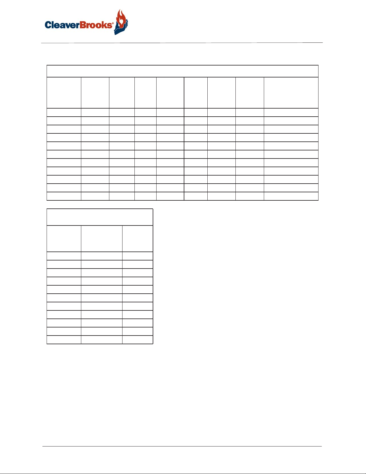
Standard Specifications for EG-EL-ELG Series: Gas, #2 Oil, Gas/Oil Configuration
Separate
Burner
Model
E-84-1 8,400 60 200 4 3 3 1/2 208/230/460/3/60
E-105-1 10,500 75 250 4 5 3 1/2 208/230/460/3/60
E-126-1 12,600 90 300 4 5 3 1/2 208/230/460/3/60
E-147-1 14,700 105 350 4 7 1/2 5 1/2 208/230/460/3/60
E-168-2 16,800 120 400 4 10 5 1/2 208/230/460/3/60
E-210-2 21,000 150 500 4 15 5 3/4 208/230/460/3/60
E-252-2 25,200 180 600 4 15 7 1/2 3/4 230/460/3/60
E-294-3 29,400 210 700 4 20 7 1/2 3/4 230/460/3/60
E-336-3 33,600 240 800 4 20 7 1/2 3/4 460/3
E-378-3 37,800 270 900 4 25 15 1 460/3
E-420-3 42,000 300 1,000 4 30 15 1 460/3
Gas Input
MBtu/hr
#2 Oil
Input
US GPH
BHP
@80%
Eff.
Furnace
Pressure
(“W.C.)
Blower
Motor
HP
Comp.
Module
Motor HP
3 PH
Metering
System
Motor HP
3 PH.
Blower Motor
Volt/PH 60 Hz.
Standard Specifications for EG-EL-ELG Series:
Gas, #2 Oil, Gas/Oil Configuration
Burner
Model
E-84-1 2 1/2 2.1
E-105-1 3 2.2
E-126-1 3 2.5
E-147-1 3 2.7
E-168-2 3 3.0
E-210-2 3 3.9
E-252-2 3 4.3
E-294-3 3 2.6
E-336-3 3 3.1
E-378-3 4 3.6
E-420-3 4 3.7
Standard Gas
Train Pipe Size
(in.)
Gas
Pressure
Required
(PSI)
NOTES:
Input is based on fuel BTU content, listed furnace pressure
and altitude of 2,000 feet or less. If altitude >2,000 feet and
<8,000 feet, derate capacity 4% per 1,000 feet over 2,000.
Consult factory for higher altitudes. If furnace pressure
exceeds listed value, derate capacity 5% for every 0.5 “w.c.
of pressure in excess of stated. Consult factory if derate
exceeds 20%. Gas input is based on natural gas with 1,000
BTU/cu. ft., 0.60 gravity, 0 furnace pressure and the
aforementioned conditions. For total pressure at manifold,
add furnace pressure. Oil input based on 140,000 BTU/gal.
and the aforementioned conditions. Consult factory for 50
Hz. applications.
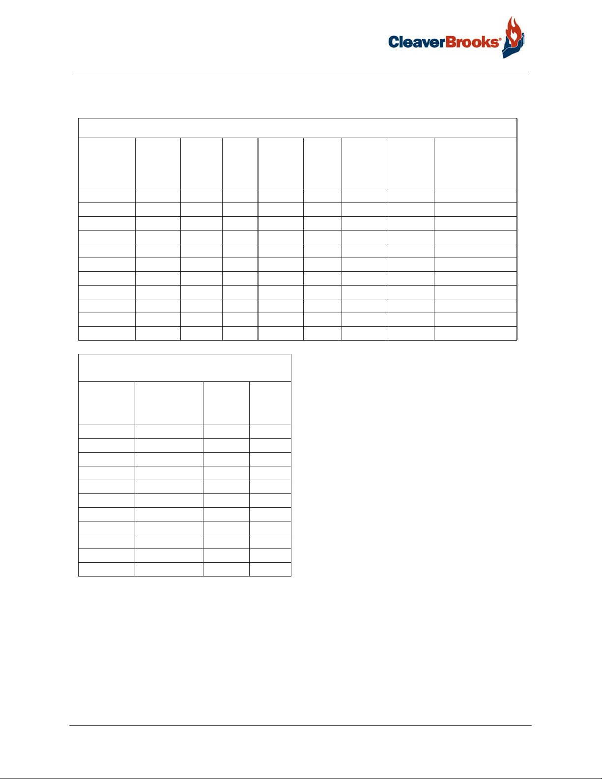
<30 PPM Low NOx Standard Specifications for LNEG-LNELG Series: Gas, Gas/Oil Configuration
Separate
Burner
Model
LNE-84-1 8,400 60 200 4 5 3 1/2 208/230/460/3/60
LNE-105-1 10,500 75 250 4 5 3 1/2 208/230/460/3/60
LNE-126-1 12,600 90 300 4 7 1/2 3 1/2 208/230/460/3/60
LNE-147-1 14,700 105 350 4 10 5 1/2 208/230/460/3/60
LNE-168-2 16,800 120 400 4 15 5 1/2 208/230/460/3/60
LNE-210-2 21,000 150 500 4 20 5 3/4 208/230/460/3/60
LNE-252-2 25,200 180 600 4 25 7 1/2 3/4 230/460/3/60
LNE-294-3 29,400 210 700 4 25 7 1/2 3/4 230/460/3/60
LNE-336-3 33,600 240 800 4 30 7 1/2 3/4 460/3
LNE-378-3 37,800 270 900 4 40 15 1 460/3
LNE-420-3 42,000 300 1,000 4 50 15 1 460/3
Gas
Input
MBtu/hr
#2 Oil
Input
US GPH
BHP
@80%
Eff.
Furnace
Pressure
(“W.C.)
Blower
Motor
HP
Comp.
Module
Motor HP
3 PH
Metering
System
Motor HP
3 PH.
Blower Motor
Volt/PH 60 Hz.
<30 PPM Low NOx Standard Specifications for LNEG-
LNELG Series: Gas, Gas/Oil Configuration
Burner
Model &
Frame Size
LNE-84-1 2 1/2 2.1 6
LNE-105-1 3 2.2 6
LNE-126-1 3 2.5 6
LNE-147-1 3 2.7 6
LNE-168-2 3 3.0 8
LNE-210-2 3 3.9 8
LNE-252-2 3 4.3 8
LNE-294-3 3 2.6 12
LNE-336-3 3 3.1 12
LNE-378-3 3 3.6 12
LNE-420-3 4 3.7 12
Standard Gas
Train Pipe Size
Gas
Pressure
Required
(PSI)
FGR
Line
Piping
Size
NOTES:
Input is based on fuel BTU content, listed furnace
pressure and altitude of 2,000 feet or less. If altitude
>2,000 feet and <8,000 feet, derate capacity 4% per
1,000 feet over 2,000. Consult factory for higher
altitudes. If furnace pressure exceeds listed value,
derate capacity 5% for every 0.5 “w.c. of pressure in
excess of stated. Consult factory if derate exceeds
20%. Gas input is based on natural gas with 1,000
BTU/cu. ft., 0.60 gravity, 0 furnace pressure and the
aforementioned conditions. For total pressure at
manifold, add furnace pressure. Oil input based on
140,000 BTU/gal. and the aforementioned conditions.
Consult factory for 50 Hz. applications.

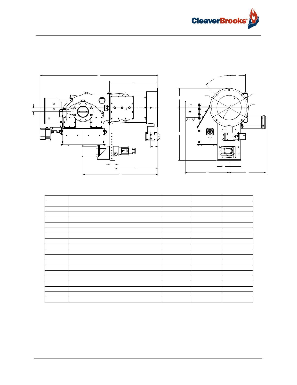
E Series Standard Dimensions - Uncontrolled NOx Configuration
Accompanying dimensions are for layout purposes only
B
A
M
T
N
E
C
DIMENSION
DESCRIPTION SIZE 1
A MOUNTING FLANGE TO PIN
D MOUNTING FLANGE TO SUPPORT
E MOUNTING FLANGE TO GAS INLET
F CENTER LINE TO HINGE
ØG
ØH
ØI
J
ØK
OUTER DIAMETER
INNER DIAMETER
DIAMETER OF BOLT CIRCLE
NUMBER OF MOUNTING HOLE 8 12 8
DIAMTER OF BOLT HOLE
L° OFFSET OF BOLT CIRCLE FROM STARTING POINT
M CENTER LINE TO TOP
N CENTER LINE TO BOTTOM
R CENTER LINE TO RIGHT SIDE 20" 23"
S CENTER LINE TO LEFT SIDE
D
26-1/4" 34-1/16" 36-7/16"
HTGNEL LLAREVOB
HTGNEL TROPPUSC
63-7/8" 77-7/16" 84-9/32"
2-3/4" 2-3/4"
23-1/4" 31-1/2" 33-5/8"
3-3/4"
8-7/8" 10-3/16" 11-11/16"
21"
13-3/8"
19-1/4"
3/4" 15/16" 3/4"
45 15 45
10-1/2"
28-5/8" 36-1/2"
HTDIW TROPPUSP
13-3/16" 13-3/16" 14-3/4"
17-1/2" 18-1/4" 23-7/16"
L°
ØG
P
S R
SIZE 2 SIZE 3
5"
26" 30"
16" 19"
24"
13" 15"
ØH
F
ØI
JX ØK
3
6-5/8"
28-1/4"
42"
26-1/2"
E Series Standard Dimensions - <30 PPM Low NOx Configuration
Accompanying dimensions are for layout purposes only
T
B
A
M
T
N
E
C
U
DIMENSION
A MOUNTING FLANGE TO PIN
DESCRIPTION
D MOUNTING FLANGE TO SUPPORT
E MOUNTING FLANGE TO GAS INLET
F CENTER LINE TO HINGE
ØG
ØH
ØI
J
ØK
OUTER DIAMETER
INNER DIAMETER
DIAMETER OF BOLT CIRCLE
NUMBER OF MOUNTING HOLE 8 12 8
DIAMTER OF BOLT HOLE
L° OFFSET OF BOLT CIRCLE FROM STARTING POINT
M CENTER LINE TO TOP
N CENTER LINE TO BOTTOM
R CENTER LINE TO RIGHT SIDE 20" 23"
S CENTER LINE TO LEFT SIDE
T CENTER LINE TO CENTER LINE OF FGR
U
MOUNTING FLANGE TO CENTER LINE OF FGR
D
SIZE 1
26-1/4" 34-1/16" 36-7/16"
HTGNEL LLAREVOB
HTGNEL TROPPUSC
63-7/8" 77-7/16" 84-9/32"
2-3/4" 2-3/4"
23-1/4" 31-1/2" 33-5/8"
3-3/4"
8-7/8" 10-3/16" 11-11/16"
21"
13-3/8"
19-1/4"
3/4" 15/16" 3/4"
45 15 45
10-1/2"
28-5/8" 36-1/2"
HTDIW TROPPUSP
13-3/16" 13-3/16" 14-3/4"
17-1/2" 18-1/4" 23-7/16"
2-3/16" 6-1/16" 6-13/32"
40-5/8" 50-1/8" 55-1/4"
L°
ØG
S
F
ØH
P
SIZE 2 SIZE 3
3
5"
6-5/8"
26" 30"
16" 19"
24"
28-1/4"
13" 15"
42"
26-1/2"
ØI
JX ØK
R

Profire E/LNE Series
Table of Contents
CHAPTER 1 Introduction 1-1
1.1 — Overview 1-1
1.2 — Description 1-1
1.3 — Operating Controls 1-2
1.3.1 — Control Panel 1-2
1.3.2 — Flame Safeguard Controls 1-2
1.3.3 — Firing Rate Controls 1-3
1.4 — Combustion Air Handling System 1-3
1.5 — Firing Head 1-3
1.6 — Oil System Air Atomizing 1-4
1.6.1 — 3-Way Solenoid Valve 1-4
1.6.2 — Nozzle Assembly 1-4
1.6.3 — Oil Strainer 1-4
1.6.4 — Atomizing Air Proving Switch 1-4
1.6.5 — Oil Metering 1-5
1.6.6 — Separate Compressor Module 1-5
1.7 — Gas System 1-6
1.7.1 — Main Gas Train Components 1-6
1.7.2 — Pilot Gas Train Components 1-8
1.7.3 — Operation 1-9
CHAPTER 2 Installation 2-1
2.1 — Application 2-1
2.2 — Draft Conditions 2-1
750-297
Profire E/LNE Series Manual
i

2.3 — Combustion Chamber Recommendations and E Refractory Dimensions 2-2
2.3.1 — Watertube Boiler Dimensions 2-2
2.3.2 — Firetube Boiler Dimensions 2-3
2.4 — Installation 2-5
2.4.1 — General 2-5
2.4.2 — Refractory Dry Oven 2-5
2.5 — Separate Compressor Module 2-7
2.6 — Typical Oil Supply Loop 2-7
2.7 — Oil Circulating Loop Operation 2-8
2.8 — Circulating Oil Pump 2-11
2.9 — Back Pressure Valve 2-11
2.10 — Gas Piping 2-11
2.11 — Installation Checklist 2-12
CHAPTER 3 Operation 3-1
3.1 — Preparations for Starting 3-1
3.1.1 — Oil Flow 3-2
3.1.2 — Oil Pressure 3-2
3.1.3 — Firing Preparations for Oil Burners 3-2
3.1.4 — Firing Preparations for Gas Burners 3-2
3.2 — Electrical Interference Test 3-2
3.2.1 — Gas Fired 3-3
3.2.2 — Oil Fired 3-3
3.3 — Gas Pilot Flame Adjustment 3-3
3.4 — Startup Sequence 3-3
3.5 — Automatic Shutdown 3-4
ii
Profire E/LNE Series Manual
750-297

3.6 — Manual Shutdown 3-4
3.7 — Safety Shutdown 3-4
3.8 — Startup and Operating 3-5
3.8.1 — Gas Burners 3-5
3.8.2 — Oil Burners 3-6
3.9 — Normal Operation 3-6
3.10 — Shutdown 3-6
CHAPTER 4 Adjustments 4-1
4.1 — Overview 4-1
4.2 — Combustion Adjustment on Gas and Oil 4-1
4.2.1 — Stack Temperature 4-1
4.2.2 — Smoke Measurement 4-2
4.2.3 — Gas Adjustments 4-2
4.2.4 — Fuel Oil Adjustments 4-2
4.3 — Electrical Interference Test 4-2
4.3.1 — Gas Fired 4-2
4.3.2 — Oil Fired 4-2
4.4 — Gas System 4-3
4.4.1 — Gas Pressure 4-3
4.4.2 — Gas Flow 4-3
4.4.3 — Gas Pilot Flame Adjustment 4-3
4.4.4 — Main Gas Pressure Regulator 4-3
4.4.5 — Low Gas Pressure Switch 4-3
4.4.6 — High Gas Pressure Switch 4-4
4.4.7 — Gas Combustion Adjustment 4-4
4.5 — Oil System 4-4
4.5.1 — Oil Metering System 4-4
4.5.2 — Atomizing Air Pressure 4-5
4.5.3 — Atomizing Air Proving Switch 4-5
4.5.4 — Low Oil Pressure Switch 4-5
4.6 — Linkage and Modulating Motor 4-5
750-297
Profire E/LNE Series Manual
iii

4.7 — Cam Trim Adjustment 4-6
4.8 — Parallel Positioning Adjustment 4-7
4.9 — Firing Rate Controls 4-7
4.10 — Dual Manifold Systems 4-9
4.10.1 — Gas Metering Valve Theory of Operation 4-9
4.10.2 — Gas Meterng Valve Setup 4-10
CHAPTER 5 Maintenance 5-1
5.1 — Overview 5-1
5.2 — Control System 5-1
5.2.1 — Programming Control 5-2
5.3 — Impeller and Inlet Cone 5-2
5.4 — Firing Head Inspection 5-2
5.5 — Pilot and Ignition Electrode 5-3
5.6 — Flame Scanner 5-3
5.7 — Oil Nozzle 5-3
5.8 — Diffuser 5-4
5.9 — Firing Rate Controls 5-5
5.10 — Burner Mounting Inspection 5-5
5.11 — Fuel Oil System 5-5
5.11.1 — Fuel Oil Circulating Pump 5-5
5.11.2 — Fuel Oil Strainers 5-5
iv
5.12 — Primary Compressor System 5-6
5.12.1 — Primary Compressor 5-6
750-297
Profire E/LNE Series Manual

5.12.2 — Air Cleaner 5-6
5.12.3 — Air-Oil Tank 5-6
5.12.4 — Oil Level Sight Gauge 5-7
5.12.5 — Compressor Oil Filter (Lube Oil Strainer) 5-7
5.12.6 — Compressor Lubrication 5-7
5.13 — Gas System 5-7
5.13.1 — Motorized Main Gas Valves 5-7
5.13.2 — Solenoid Valves 5-7
5.13.3 — Gas Pressure Regulators 5-8
5.13.4 — Gas Pressure Switches 5-9
5.14 — Electrical System 5-8
5.14.1 — Electric Motors 5-8
5.15 — Checking Flame Failure 5-8
5.15.1 —Pilot Flame Failure 5-8
5.15.2 — Failure to Light Main Flame 5-8
5.15.3 — Loss of Flame 5-9
5.16 — Extended Shutdown 5-9
5.17 — Recommended Maintenance Schedule 5-10
CHAPTER 6 Troubleshooting 6-1
6.1 — Awareness 6-1
6.2 — Emergency Shutdown 6-2
6.3 — Problem/Possible Causes 6-3
CHAPTER 7 Accessories 7-1
7.1 — Overview 7-1
7.2 — Steam Atomizing System 7-1
7.3 — Air Purge System (optional) 7-2
750-297
Profire E/LNE Series Manual
7.4 — Plant Air System 7-2
v

CHAPTER 8 LNE Series FGR System 8-1
8.1 — Description 8-1
8.2 — FGR Shutoff Valve 8-2
8.3 — FGR Control Valve 8-2
8.4 — Air/FGR Damper Assembly 8-4
8.5 — Stack Temperature Interlock 8-4
STARTUP/SERVICE REPORT
WARRANTY POLICY
vi
750-297
Profire E/LNE Series Manual
CHAPTER 1 Introduction
1.1 — Overview
E series burners are assembled, wired, and tested at the factory . They are listed by the Underwriters Laboratory, CSD-1,
NFPA-85, F.M., including the national Electrical Code (NEC), and associated insurance underwriters. Where
applicable, the Canadian Gas Association (CGA) B149 and the Canadian Standards Association (CSA) B140 codes
shall prevail. Other regulatory agency control options are available.
Caution
!
Only factory authorized burner service personnel should start up, adjust, or service this equipment.
The operator must be familiar with the individual functioning of all controls to understand the operations and procedures described in this manual.
1.2 — Description
The E series burners are designed to operate with gas and light oil. The E series oil burners are of the low pressure, air
atomizing (nozzle) type, while the gas burners are of the peripheral mix type. The E series burner operates with full
modulation on gas, light oil or a combination, and features a spark-ignited gas pilot flame. A switch permits
changeover from automatic fully modulated firing to manually set firing at any desired rate between minimum and
maximum. Additional safeguards assure that the burner always returns to the minimum firing position for ignition.
E series burners are designed for automatic, unattended operation except for periodic inspection and maintenance.
After selecting the proper overload settings for the starter, the rest of the control panel components require little
attention except for occasional cleaning.
750-297
Profire E/LNE Series Manual
1-1

Introduction
1.3 — Operating Controls
1.3.1 — Control Panel
The control panel contains a flame safeguard programming control, motor starters, relays, time delays, and terminal
strips mounted internally on a panel sub-base. Lights, switches, potentiometers, a control circuit breaker, and flame
safeguard displays are mounted externally on the panel.
Component Details
On-Off Burner Switch For gas or oil only.
Fuel Selector Switch Gas-Off-Oil
For combination gas-oil burners only.
a) Gas Position: Selects gas as the firing fuel.
b) Off Position: Burner off.
c) Oil Position: Selects oil as the firing fuel.
NOTE: When changing from oil to gas fuel, allow the programmer to complete
post-purge and shutdown before moving the selector switch to the gas position.
This will allow the interlock circuit to de-energize at either the oil-air pump or
the compressor.
Control Circuit Breaker Supplementary low overcurrent protection only. No larger than 15 amps.
Auto-Manual Modulation Selector
Switch
Manual Modulating Control 135 ohm Increases or decreases the burner firing rate manually.
Signal Lamps a) Power On (white): Illuminates when the control circuit is energized (pow-
a) Auto Position: Selects boiler modulation control.
b) Manual Position: Selects 135 ohm potentiometer for manual modulating
control.
ered).
b) Ignition (amber): Illuminates when the ignition transformer is powered, and
gas pilot valve is energized (open).
c) Main Fuel (green): Illuminates when the main fuel valve or valves (gas or oil)
are energized (open).
d) Flame Failure (red): Illuminates when the flame safeguard system fails to
detect pilot or main flame.
1.3.2 — Flame Safeguard Controls
The flame safeguard programmer incorporates a flame sensing cell (scanner) to shut down the burner in the event of
pilot flame or main flame failure. Other safety controls shut down the burner based on sequence of operation as shown
in the manufacturer’s flame safeguard manual.
Warning
!
Read the flame safeguard manual and fully understand its contents before attempting to operate this equipment. Failure to
do so may result in serious personal injury or death.
1-2
Profire E/LNE Series Manual
750-297
Introduction
1.3.3 — Firing Rate Controls
Regardless of the fuel used, burner input is fully modulated between low fire and high fire on boiler demand. The firing
rate is controlled by the potentiometer-regulated modulating motor. The combustion air control damper, oil metering
pump, and/or gas volume butterfly valve are controlled through variable rate rod and lever linkages. The modulating
motor rotates 90º from low to high position. Flow rate through each component is adjusted by positioning the control
rods on the levers and the angular position of levers on shafts. The lever on the modulating motor shafts actuate the
high fire position proving switch.
1.4 — Combustion Air Handling System
The combustion air handling system consists of two major components:
Component Details
Damper Assembly A rotary damper regulates the combustion air volume and is positioned by a
modulating motor. The damper is normally almost closed in the low fire position
and opens as the burner drives toward a high fire position.
Motor Driven Impeller The diameter of the impeller determines available air pressure and the width
determines air capacity in cubic feet per minute. Alternate motor-impeller
combinations are available for 50 cycle or 60 cycle power and for firing against
either moderate or high furnace pressure. All standard impellers are sized for up
to 2,000 ft. altitudes and up to 4” W.C. furnace pressures. Alternate impeller
wheels are available. For higher altitudes and higher furnace pressures, motor
and impeller combinations are determined at the factory.
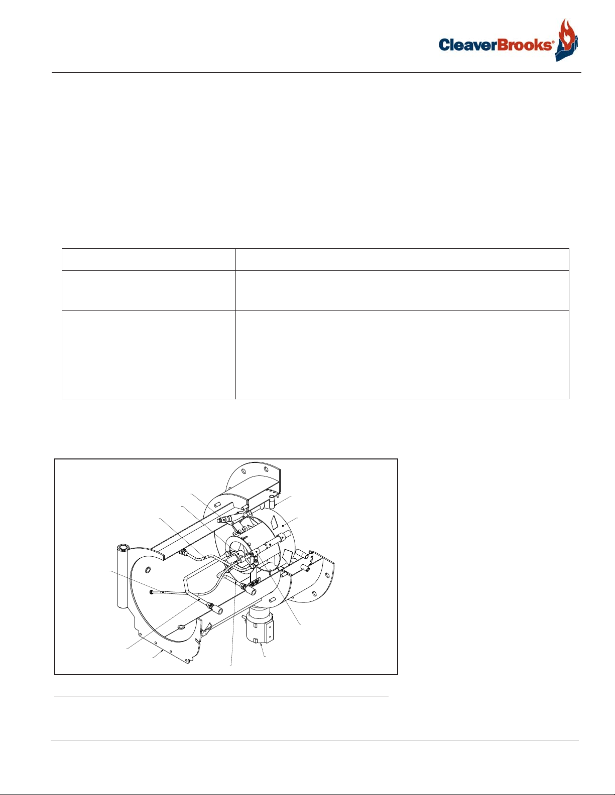
1.5 — Firing Head
AIR ATOMIZING OIL NOZZLE ASSEMBLY
ELECTRODE LEAD
ATOMIZING AIR LINE
FIGURE 1-1. Burner Housing
(SINGLE OR DUAL)
GAS PILOT LINE
BURNER HOUSING
FLAME SCANNER
FUEL OIL LINE
GAS INLET
GAS SPUDS
AIR DIFFUSER
GAS PILOT ASSEMBLY
WITH ELECTRIC SPARK IGNITION
Access to the firing head is provided by
swinging open the impeller housing.
First, disconnect the damper linkage,
release the housing latch, and swing the
housing to the open position. An
internal gas pilot is standard on all
burners. Pilot gas pressure is adjusted at
the pilot pressure regulator.
750-297
Profire E/LNE Series Manual
1-3
Introduction
1.6 — Oil System Air Atomizing
E Model burners use compressed air for atomization. Atomizing air is independent of combustion air. The system is
supplied with a separate compressor module for mounting near the burner.
1.6.1 — 3-Way Solenoid Valve
Metered oil enters the common port of the 3-way solenoid valve. During shutdown, pre- and post-purge, the valve is
de-energized (N.C. port closed) and all metered fuel oil returns to the storage tank. When the valve is energized,
metered oil is directed to the nozzle through the N.C. port.
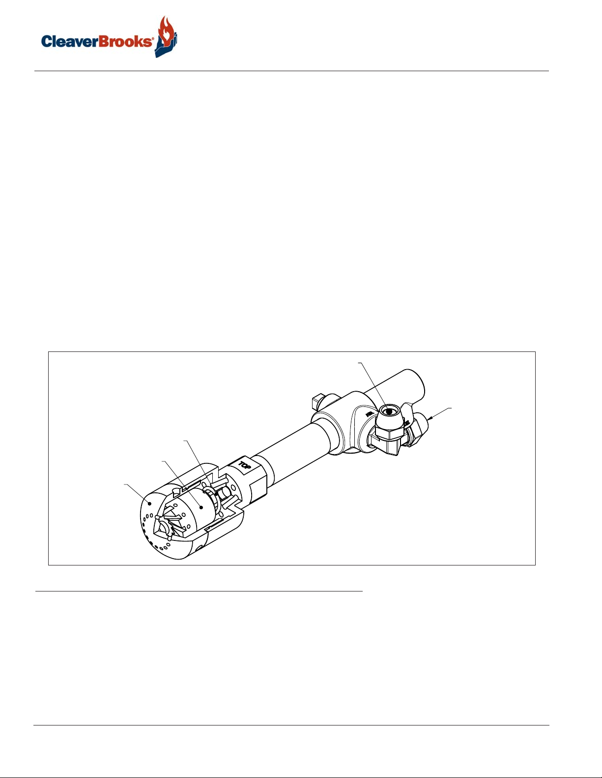
1.6.2 — Nozzle Assembly
The nozzle assembly consists of four main parts: body, compression spring, swirler, and tip. The swirler is held against
the nozzle tip by the compression spring. The nozzle body has inlet ports for air and oil lines. Metered fuel oil enters
the nozzle body and flows through a tube to the swirler. Oil is forced from the core of the swirler to the side ports where
it meets with the atomizing air. Atomizing air enters and passes through the nozzle body to grooves in the swirler,
where it mixes with fuel oil. Air/oil passes through grooves and out of the nozzle orifice in a cone of atomized oil.
Proper velocity and angle of the fine spray ensures good mixing with the combustion air, providing quiet starts and
excellent combustion efficiency. During pre- and post-purge, the nozzle tip is purged with air. This prevents afterdrip or
baked-on residue.
SPRING
SWIRLER
NOZZLE TIP
FIGURE 1-2. Nozzle Assembly
1.6.3 — Oil Strainer
Prevents foreign matter from entering the burner oil system.
ATOMIZING AIR
FUEL OIL
1.6.4 — Atomizing Air Proving Switch
Pressure actuated switch contacts close when sufficient atomizing air pressure is present. The oil valve will not open
unless switch contacts are closed.
1-4
Profire E/LNE Series Manual
750-297

Introduction
1.6.5 — Oil Metering
Fuel oil under nominal pressure in the circulating loop flows to the adjustable positive displacement (volumetric
metering unit). Oil metering is accomplished by changing the piston stroke by means of an eccentric shaft and pin
assembly. The pistons reciprocate in a rotor assembly, turning in a hardened steel sleeve having oil inlet and discharge
slots. During each revolution the pistons go through the following cycle:
1. Inlet Cycle. The piston is at the bottom dead center position. At this position, the cavity between the top of the
piston and the outside diameter of the rotor fills with oil.
2. Discharge Cycle. (180º from inlet cycle) The piston is at the top dead center position. At this position, the oil is
forced out of the discharge port to the nozzle. The piston stroke length is determined by the position of the eccentric
shaft and plate. The piston adjustment plate is positioned by an adjustable eccentric shaft. The eccentric shaft is
positioned by the modulator through adjustable linkage. Counterclockwise rotation of the eccentric shaft increases
the piston stroke (more oil delivered to nozzle); clockwise rotation decreases the amount of oil delivered. When the
eccentric shaft is stationary, at any position, the stroke of the pistons remains constant delivering a constant volume
of oil regardless of viscosity.
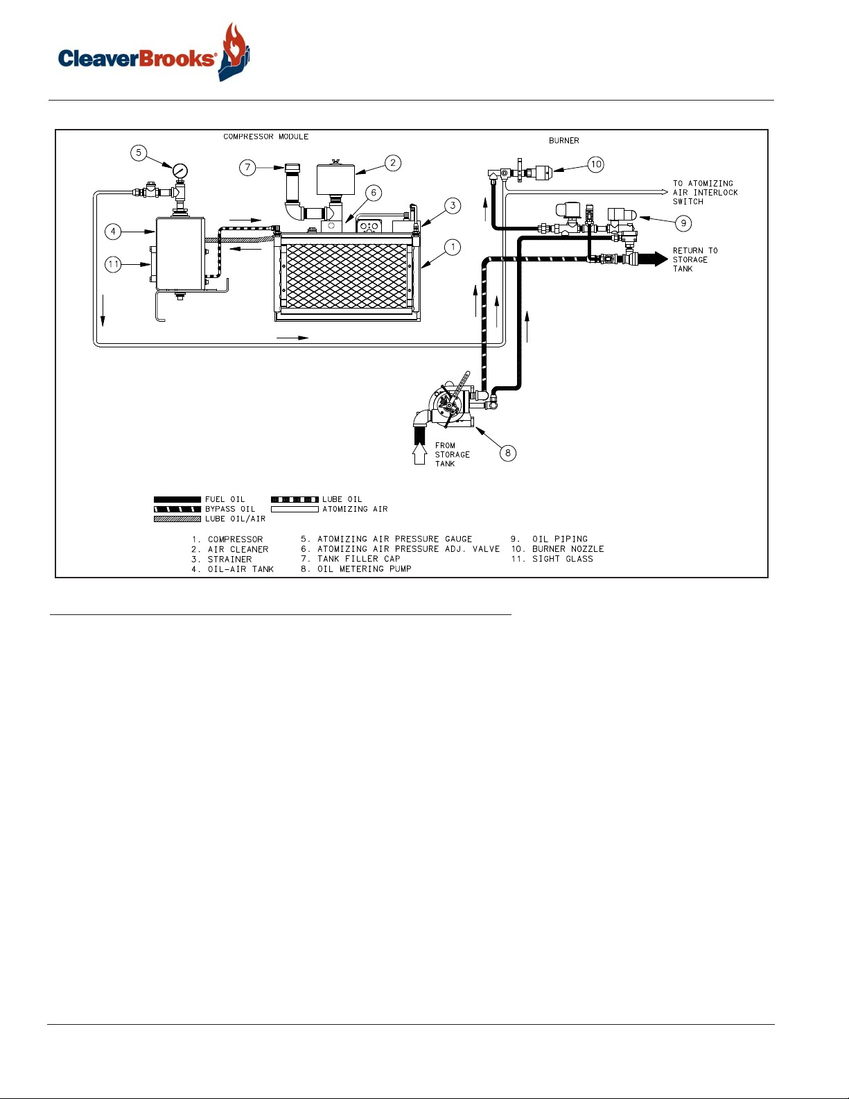
1.6.6 — Separate Compressor Module
EL and ELG burners have a burner mounted oil metering unit and a separate compressor module. The system functions
as follows:
Air is supplied by a positive displacement rotary vane compressor. This provides a constant volume of atomizing air
regardless of pressure. The compressor module includes motor , air-oil reservoir tank, air filter, and lube oil cooling coil.
Air enters the compressor through the filter. The air flows from the compressor into the air-oil separating and reservoir
tank. Filtering material and baffles separate the lube oil from the compressed air. The tank air pressure forces
lubricating oil from the tank to the compressor to lubricate bearings and vanes. A sight glass indicates the level of
lubricating oil in the air/oil reservoir. Lubricating oil must be visible in the gauge glass at all times. Air compression
heat is absorbed in part by the flow of lube oil, creating a hot oil mist. The air/oil mist is cooled by a coil assembly.
Lube oil is also cooled before entering the compressor.
Fuel is delivered to the positive displacement metering pump at 10 to 15 psi. Metered oil is delivered to the common
port of a 3-way solenoid valve for transfer to the burner nozzle through the normally closed port or back to the storage
tank through the normally open port. During pre- and post-purge, metered oil is returned to the tank. During normal
firing, all metered oil is delivered to the nozzle. For the description of typical fuel oil piping installations, see Chapter 2.
Air enters a rotary vane compressor through an air cleaner where it is compressed to atomizing pressure. Air flows from
the compressor to an air/oil tank which serves the multiple purpose of dampening air pulsation, lube oil mist recovery,
lube oil and atomizing air storage. The compressor rotor is cooled and lubricated continuously by oil under pressure
from the air/oil tank. Oil vapor is extracted by a mist eliminator in the upper section of the tank. Atomizing air from the
upper tank section is delivered to the nozzle at a constant volume. Air pressure increases as the burner firing rate
increases. Atomizing pressure may be adjusted by the needle valve located on the air-oil pump. The valve allows air to
be bled from the tank to the compressor inlet. Delivery rate of the fuel oil metering pump is controlled by the
modulating motor through adjustable linkage.
750-297
Profire E/LNE Series Manual
1-5
Introduction
FIGURE 1-3. Compressor Module and Burner
1.7 — Gas System
Gas is introduced into the combustion zone from a circular manifold through multiple ports in the manifold. Firing rate
is determined by the size and number of ports, by manifold pressure, and by combustion zone pressure. The firing rate
is regulated by a rotary, butterfly-type throttling valve at the manifold inlet. The valve is actuated by an adjustable
linkage from the modulating motor. Depending upon specific requirements, one or two safety shutoff motorized main
gas valves are provided for installation in the gas train upstream of the butterfly valve. Safety shutoff gas valves are
wired into the programming control to automatically open and close at the proper time in the operating sequence.
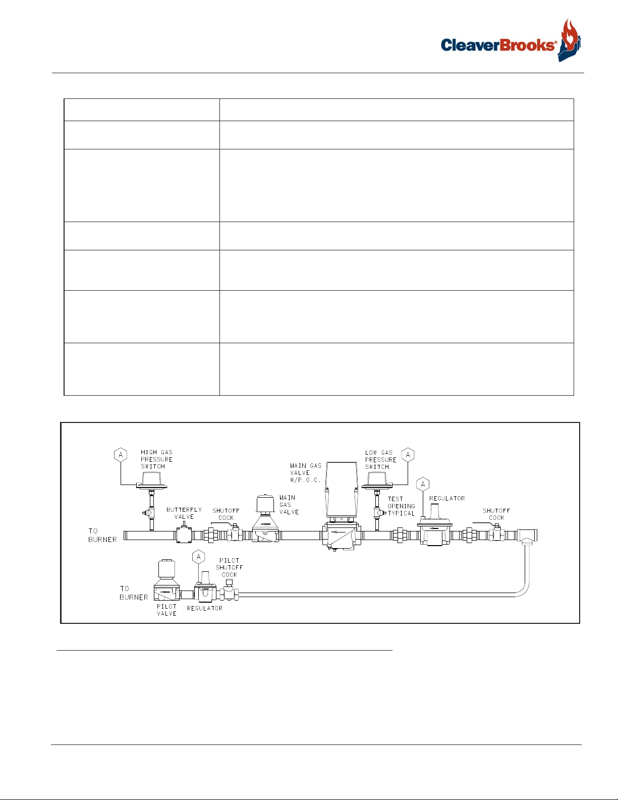
1.7.1 — Main Gas Train Components
Depending upon the requirements of the regulating authority , the gas control system and gas train may consist of some,
or all, of the following items:
1-6
750-297
Profire E/LNE Series Manual
Introduction
Component Description
Gas Volume Valve The butterfly-type valve is positioned by linkage from the modulating motor and
controls the rate of flow of the gas.
Main Gas Valves Electrically operated safety shutoff valve(s) that open to admit gas to the burner.
Standard U.L. burners include:
• Models E84-105: One motorized gas valve w/closure interlock and one solenoid
valve.
• Models E126-630: Two motorized gas valves, one w/closure interlock.
Main Gas Regulator Regulates gas train pressure to specified pressure required at inlet to the gas train.
Input is set my the main gas pressure regulator adjustment.
Main Gas Cocks For manual shutoff of the gas supply upstream of the pressure regulator. A second
shutoff cock downstream of the main gas valve(s) provides a means of testing for
leakage through the gas valve(s).
High Gas Pressure Switch A pressure actuated switch that remains closed when gas pressure is below a pre-
selected setting. Should the pressure rise above the setting, the switch contacts will
open causing main gas valve(s) to close. This switch requires manual reset after
being tripped.
Low Gas Pressure Switch A pressure actuated switch that remains closed when gas pressure is above a pre-
selected setting. Should the pressure drop below this setting, the switch contacts will
open, causing main gas valve(s) to close. This switch requires manual reset after
being tripped.
FIGURE 1-4. Main Gas Train (Model E84 - E105)
750-297
Profire E/LNE Series Manual
1-7
Introduction
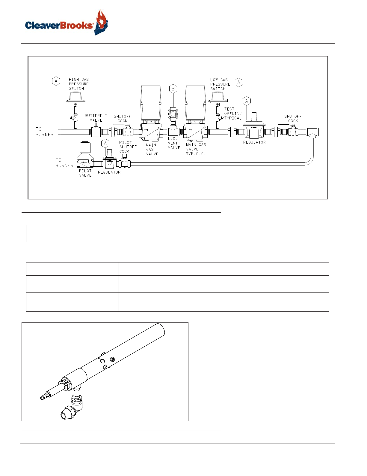
FIGURE 1-5. Main Gas Train (Model E126-E420)
NOTE: These piping layouts are for reference only and are subject to change without notice. Optional equipment may
change a layout.
1.7.2 — Pilot Gas Train Components
Component Description
Gas Pilot Valve A solenoid valve that opens during the ignition period to admit fuel to the pilot. It
closes after main flame is established.
Gas Pressure Regulator Reduces gas pressure to that required by the pilot.
Gas Pilot Shutoff Cock For manually closing the pilot gas supply.
FIGURE 1-6. Gas Pilot
1-8
750-297
Profire E/LNE Series Manual

Introduction
1.7.3 — Operation
Metered gas flows through the main gas shutoff cock, through the pressure regulator to the automatic gas valves and
butterfly valve to the gas manifold.
The butterfly gas valve modulates flow to burner input demand. The butterfly valve is positioned through mechanical
linkage by the modulating motor. The air control damper is positioned simultaneously by the modulating motor.
The automatic gas valve(s) cannot be energized unless the combustion air proving switch is closed. The low and high
gas pressure switches must be closed to prove proper gas pressure.
A normally open vent valve, if required, is located between the two automatic gas valves. This valve is shut when the
automatic gas valves are open. When the automatic valves are closed, the vent valve is open for venting gas to the
outside, should any be present.
750-297
Profire E/LNE Series Manual
1-9

Introduction
1-10
750-297
Profire E/LNE Series Manual

CHAPTER 2 Installation
2.1 — Application
Electrical power available is usually 208 volt, 3-phase, 60 cycle, 230/460 volt, 3-phase, 60 cycle or 380 volt,
3-phase, 50 cycle. Control circuit is 115 volt, single phase, 60 cycle or 115 volt, single phase, 50 cycle. Refer
to the electrical schematic diagram shipped with the burner. Power connections are made at the control panel.
Wiring from the panel to burner mounted components is installed at the factory. Wiring from the burner panel to
boiler controls, low water controls, remote compressor motor, and remotely located fuel valves is furnished by the
installer.
2.2 — Draft Conditions
Automatic over-fire draft control or barometric draft regulators are not usually required except where the system
has a tall chimney. The exact height of a chimney requiring draft control is indeterminate, but draft regulation is
seldom needed for chimneys less than 50 feet high, especially with Scotch Marine or sealed firebox boilers.
750-297
Profire E/LNE Series Manual
2-1
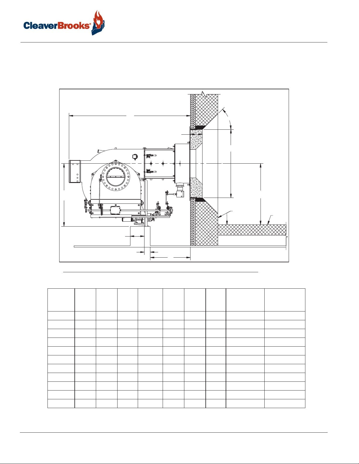
2.3 — Combustion Chamber Recommendations and E Refractory Dimensions
The combustion chamber dimensions should be proportioned to the heating load of the boiler.
2.3.1 - Watertube Boiler Dimensions
Installation
E
45°
A
B
BURNER
C
L
D
STANDARD
FIREBRICK
1-1/2" + A
F
BLOCK INSULATION
C (MIN)
FLOOR
G
FIGURE 2-1. Combustion Chamber Dimensions (Watertube Boiler)
2-2
Burner
Size A B C D E F G
84 10 19 19 31.5* 64 3.5 23 38 74
105 10 19 23 31.5* 64 3.5 23 46 84
126 10 19 24 31.5* 64 3.5 23 50 90
147 12 22 25 31.5* 64 3.5 23 55 100
168 12 27.5 27 37* 78 3.5 31 60 108
210 12 27.5 30 37* 78 3.5 31 70 120
252 15 31.5 30 37* 78 3.5 31 84 132
294 15 31.5 32 42* 87 3.5 33 84 144
336 18 34.6 34 42* 87 3.5 33 86 152
378 18 34.6 36 42* 87 3.5 33 92 160
420 18 34.6 38 42* 87 3.5 33 96 170
* Dimension is for oil applications. Dimension will be less for gas only applications.
Combustion
Chamber
Min. Width
Combustion
Chamber Min.
Length
Profire E/LNE Series Manual
750-297
 Loading...