

Cleaver-Brooks Profire E-84-1, Profire LNE, Profire E-126-1, Profire E-105-1, Profire E-147-1 Installation Operation & Maintenance
...Page 1

Table Of Contents
Profire E/LNE
Burner
Light Oil, Gas, or Combination
Installation
Operation
Maintenance
Manual Part No. 750-297 07/2019
Page 2

E/LNE SERIES
Installation, Operation, and Service Manual
Manual Number: 750-297
Release Date: July 2019
Page 3

Copyright © 2019 by Cleaver-Brooks
All rights reserved. No part of this document may be reproduced, stored in a retrieval system, or transmitted in any
form or by any means without the prior written consent of Cleaver-Brooks.
Cleaver-Brooks
351 21st Street
Monroe, WI 53566
608-325-3141
www.cleaverbrooks.com
Page 4
PREFACE
Warning and caution references have been made in this manual and should be adhered to for proper operation of the burner.
Warning
!
This symbol precedes information which, if disregarded, may result in injury to the user of the burner or to
others.
Caution
!
This symbol precedes information which, if disregarded, may result in damage to the burner.
NOTE: This symbol precedes information which is vital to the operation or maintenance of the burner.
Model designations are based on the type of fuel(s) to be fired and the amount of furnace pressure to be
overcome. Burner size is based on firing rate (rated input in Btu/hr).
Model Standards Fuel-Air Atomization
EG Gas
EL #2 Oil
ELG #2 Oil and Gas
LNEG Gas
LNELG #2 Oil and Gas
Example: The model number on the nameplate is ELG-252, No. 2 oil and gas burner with input rated at
25,200 MBtu per hour, against furnace pressures up to 5” W.C. at 60hz.
NOTE: Firing at higher furnace pressures de-rates the burner by approximately 5% per 1/2 inch of additional
pressure. Consult with the factory.
The installation of a burner shall be in accordance with the regulations of authorities having jurisdiction.
The equipment must be installed in accordance with applicable local, state, or provincial installation
requirements including the National Electrical Code (NEC) and Associated Insurance Underwriters. Where
applicable, the Canadian Gas Association (CGA) B149 and Canadian Standard Association (CSA) B140
and B139 (for oil burners) codes shall prevail. OIl and gas burning equipment shall be connected to flues
having sufficient draft at all times to assure safe and proper operation of the burner.
The E Series burners are designed to burn either gas or light oil No. 1 or 2 as defined by ASTM D396-2010
specifications. Do not use gasoline, crankcase oil, or any oil containing gasoline.
Page 5
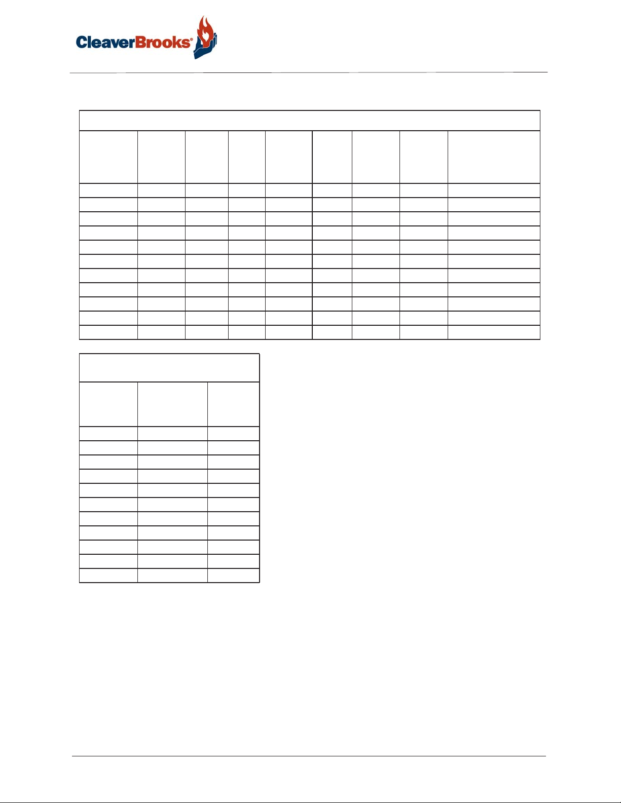
Standard Specifications for EG-EL-ELG Series: Gas, #2 Oil, Gas/Oil Configuration
Separate
Burner
Model
E-84-1 8,400 60 200 4 3 3 1/2 208/230/460/3/60
E-105-1 10,500 75 250 4 5 3 1/2 208/230/460/3/60
E-126-1 12,600 90 300 4 5 3 1/2 208/230/460/3/60
E-147-1 14,700 105 350 4 7 1/2 5 1/2 208/230/460/3/60
E-168-2 16,800 120 400 4 10 5 1/2 208/230/460/3/60
E-210-2 21,000 150 500 4 15 5 3/4 208/230/460/3/60
E-252-2 25,200 180 600 4 15 7 1/2 3/4 230/460/3/60
E-294-3 29,400 210 700 4 20 7 1/2 3/4 230/460/3/60
E-336-3 33,600 240 800 4 20 7 1/2 3/4 460/3
E-378-3 37,800 270 900 4 25 15 1 460/3
E-420-3 42,000 300 1,000 4 30 15 1 460/3
Gas Input
MBtu/hr
#2 Oil
Input
US GPH
BHP
@80%
Eff.
Furnace
Pressure
(“W.C.)
Blower
Motor
HP
Comp.
Module
Motor HP
3 PH
Metering
System
Motor HP
3 PH.
Blower Motor
Volt/PH 60 Hz.
Standard Specifications for EG-EL-ELG Series:
Gas, #2 Oil, Gas/Oil Configuration
Burner
Model
E-84-1 2 1/2 2.1
E-105-1 3 2.2
E-126-1 3 2.5
E-147-1 3 2.7
E-168-2 3 3.0
E-210-2 3 3.9
E-252-2 3 4.3
E-294-3 3 2.6
E-336-3 3 3.1
E-378-3 4 3.6
E-420-3 4 3.7
Standard Gas
Train Pipe Size
(in.)
Gas
Pressure
Required
(PSI)
NOTES:
Input is based on fuel BTU content, listed furnace pressure
and altitude of 2,000 feet or less. If altitude >2,000 feet and
<8,000 feet, derate capacity 4% per 1,000 feet over 2,000.
Consult factory for higher altitudes. If furnace pressure
exceeds listed value, derate capacity 5% for every 0.5 “w.c.
of pressure in excess of stated. Consult factory if derate
exceeds 20%. Gas input is based on natural gas with 1,000
BTU/cu. ft., 0.60 gravity, 0 furnace pressure and the
aforementioned conditions. For total pressure at manifold,
add furnace pressure. Oil input based on 140,000 BTU/gal.
and the aforementioned conditions. Consult factory for 50
Hz. applications.
Page 6
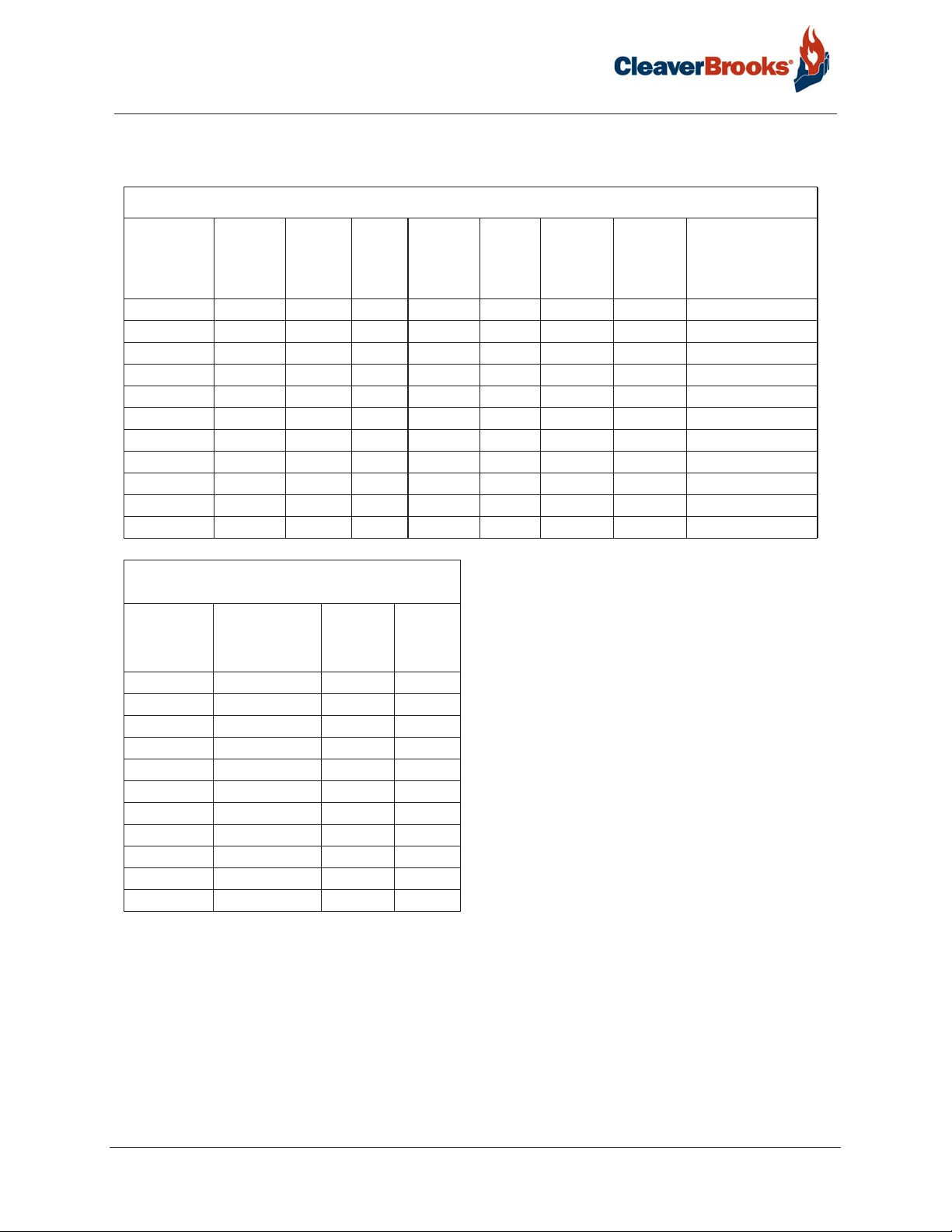
<30 PPM Low NOx Standard Specifications for LNEG-LNELG Series: Gas, Gas/Oil Configuration
Separate
Burner
Model
LNE-84-1 8,400 60 200 4 5 3 1/2 208/230/460/3/60
LNE-105-1 10,500 75 250 4 5 3 1/2 208/230/460/3/60
LNE-126-1 12,600 90 300 4 7 1/2 3 1/2 208/230/460/3/60
LNE-147-1 14,700 105 350 4 10 5 1/2 208/230/460/3/60
LNE-168-2 16,800 120 400 4 15 5 1/2 208/230/460/3/60
LNE-210-2 21,000 150 500 4 20 5 3/4 208/230/460/3/60
LNE-252-2 25,200 180 600 4 25 7 1/2 3/4 230/460/3/60
LNE-294-3 29,400 210 700 4 25 7 1/2 3/4 230/460/3/60
LNE-336-3 33,600 240 800 4 30 7 1/2 3/4 460/3
LNE-378-3 37,800 270 900 4 40 15 1 460/3
LNE-420-3 42,000 300 1,000 4 50 15 1 460/3
Gas
Input
MBtu/hr
#2 Oil
Input
US GPH
BHP
@80%
Eff.
Furnace
Pressure
(“W.C.)
Blower
Motor
HP
Comp.
Module
Motor HP
3 PH
Metering
System
Motor HP
3 PH.
Blower Motor
Volt/PH 60 Hz.
<30 PPM Low NOx Standard Specifications for LNEG-
LNELG Series: Gas, Gas/Oil Configuration
Burner
Model &
Frame Size
LNE-84-1 2 1/2 2.1 6
LNE-105-1 3 2.2 6
LNE-126-1 3 2.5 6
LNE-147-1 3 2.7 6
LNE-168-2 3 3.0 8
LNE-210-2 3 3.9 8
LNE-252-2 3 4.3 8
LNE-294-3 3 2.6 12
LNE-336-3 3 3.1 12
LNE-378-3 3 3.6 12
LNE-420-3 4 3.7 12
Standard Gas
Train Pipe Size
Gas
Pressure
Required
(PSI)
FGR
Line
Piping
Size
NOTES:
Input is based on fuel BTU content, listed furnace
pressure and altitude of 2,000 feet or less. If altitude
>2,000 feet and <8,000 feet, derate capacity 4% per
1,000 feet over 2,000. Consult factory for higher
altitudes. If furnace pressure exceeds listed value,
derate capacity 5% for every 0.5 “w.c. of pressure in
excess of stated. Consult factory if derate exceeds
20%. Gas input is based on natural gas with 1,000
BTU/cu. ft., 0.60 gravity, 0 furnace pressure and the
aforementioned conditions. For total pressure at
manifold, add furnace pressure. Oil input based on
140,000 BTU/gal. and the aforementioned conditions.
Consult factory for 50 Hz. applications.
Page 7

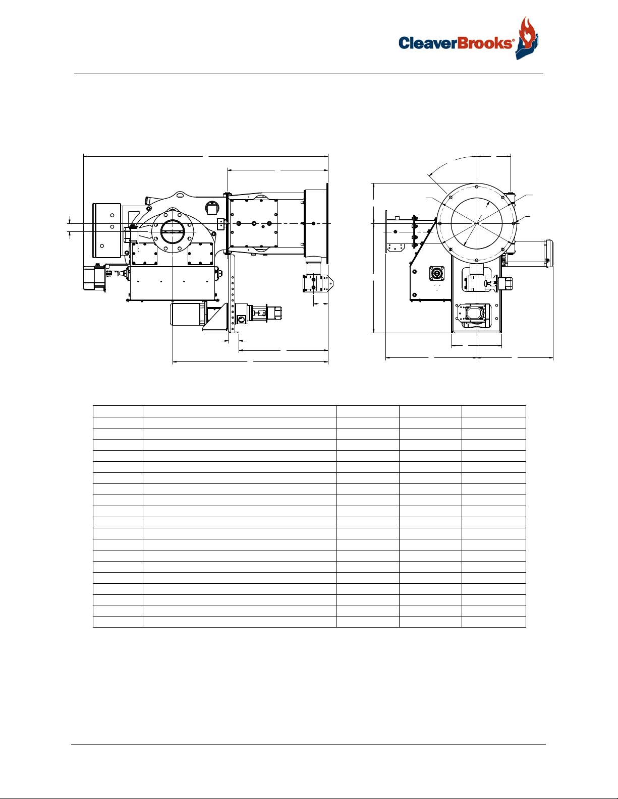
E Series Standard Dimensions - Uncontrolled NOx Configuration
Accompanying dimensions are for layout purposes only
B
A
M
T
N
E
C
DIMENSION
DESCRIPTION SIZE 1
A MOUNTING FLANGE TO PIN
D MOUNTING FLANGE TO SUPPORT
E MOUNTING FLANGE TO GAS INLET
F CENTER LINE TO HINGE
ØG
ØH
ØI
J
ØK
OUTER DIAMETER
INNER DIAMETER
DIAMETER OF BOLT CIRCLE
NUMBER OF MOUNTING HOLE 8 12 8
DIAMTER OF BOLT HOLE
L° OFFSET OF BOLT CIRCLE FROM STARTING POINT
M CENTER LINE TO TOP
N CENTER LINE TO BOTTOM
R CENTER LINE TO RIGHT SIDE 20" 23"
S CENTER LINE TO LEFT SIDE
D
26-1/4" 34-1/16" 36-7/16"
HTGNEL LLAREVOB
HTGNEL TROPPUSC
63-7/8" 77-7/16" 84-9/32"
2-3/4" 2-3/4"
23-1/4" 31-1/2" 33-5/8"
3-3/4"
8-7/8" 10-3/16" 11-11/16"
21"
13-3/8"
19-1/4"
3/4" 15/16" 3/4"
45 15 45
10-1/2"
28-5/8" 36-1/2"
HTDIW TROPPUSP
13-3/16" 13-3/16" 14-3/4"
17-1/2" 18-1/4" 23-7/16"
L°
ØG
P
S R
SIZE 2 SIZE 3
5"
26" 30"
16" 19"
24"
13" 15"
ØH
F
ØI
JX ØK
3
6-5/8"
28-1/4"
42"
26-1/2"
Page 8
E Series Standard Dimensions - <30 PPM Low NOx Configuration
Accompanying dimensions are for layout purposes only
T
B
A
M
T
N
E
C
U
DIMENSION
A MOUNTING FLANGE TO PIN
DESCRIPTION
D MOUNTING FLANGE TO SUPPORT
E MOUNTING FLANGE TO GAS INLET
F CENTER LINE TO HINGE
ØG
ØH
ØI
J
ØK
OUTER DIAMETER
INNER DIAMETER
DIAMETER OF BOLT CIRCLE
NUMBER OF MOUNTING HOLE 8 12 8
DIAMTER OF BOLT HOLE
L° OFFSET OF BOLT CIRCLE FROM STARTING POINT
M CENTER LINE TO TOP
N CENTER LINE TO BOTTOM
R CENTER LINE TO RIGHT SIDE 20" 23"
S CENTER LINE TO LEFT SIDE
T CENTER LINE TO CENTER LINE OF FGR
U
MOUNTING FLANGE TO CENTER LINE OF FGR
D
SIZE 1
26-1/4" 34-1/16" 36-7/16"
HTGNEL LLAREVOB
HTGNEL TROPPUSC
63-7/8" 77-7/16" 84-9/32"
2-3/4" 2-3/4"
23-1/4" 31-1/2" 33-5/8"
3-3/4"
8-7/8" 10-3/16" 11-11/16"
21"
13-3/8"
19-1/4"
3/4" 15/16" 3/4"
45 15 45
10-1/2"
28-5/8" 36-1/2"
HTDIW TROPPUSP
13-3/16" 13-3/16" 14-3/4"
17-1/2" 18-1/4" 23-7/16"
2-3/16" 6-1/16" 6-13/32"
40-5/8" 50-1/8" 55-1/4"
L°
ØG
S
F
ØH
P
SIZE 2 SIZE 3
3
5"
6-5/8"
26" 30"
16" 19"
24"
28-1/4"
13" 15"
42"
26-1/2"
ØI
JX ØK
R
Page 9

Profire E/LNE Series
Table of Contents
CHAPTER 1 Introduction 1-1
1.1 — Overview 1-1
1.2 — Description 1-1
1.3 — Operating Controls 1-2
1.3.1 — Control Panel 1-2
1.3.2 — Flame Safeguard Controls 1-2
1.3.3 — Firing Rate Controls 1-3
1.4 — Combustion Air Handling System 1-3
1.5 — Firing Head 1-3
1.6 — Oil System Air Atomizing 1-4
1.6.1 — 3-Way Solenoid Valve 1-4
1.6.2 — Nozzle Assembly 1-4
1.6.3 — Oil Strainer 1-4
1.6.4 — Atomizing Air Proving Switch 1-4
1.6.5 — Oil Metering 1-5
1.6.6 — Separate Compressor Module 1-5
1.7 — Gas System 1-6
1.7.1 — Main Gas Train Components 1-6
1.7.2 — Pilot Gas Train Components 1-8
1.7.3 — Operation 1-9
CHAPTER 2 Installation 2-1
2.1 — Application 2-1
2.2 — Draft Conditions 2-1
750-297
Profire E/LNE Series Manual
i
Page 10

2.3 — Combustion Chamber Recommendations and E Refractory Dimensions 2-2
2.3.1 — Watertube Boiler Dimensions 2-2
2.3.2 — Firetube Boiler Dimensions 2-3
2.4 — Installation 2-5
2.4.1 — General 2-5
2.4.2 — Refractory Dry Oven 2-5
2.5 — Separate Compressor Module 2-7
2.6 — Typical Oil Supply Loop 2-7
2.7 — Oil Circulating Loop Operation 2-8
2.8 — Circulating Oil Pump 2-11
2.9 — Back Pressure Valve 2-11
2.10 — Gas Piping 2-11
2.11 — Installation Checklist 2-12
CHAPTER 3 Operation 3-1
3.1 — Preparations for Starting 3-1
3.1.1 — Oil Flow 3-2
3.1.2 — Oil Pressure 3-2
3.1.3 — Firing Preparations for Oil Burners 3-2
3.1.4 — Firing Preparations for Gas Burners 3-2
3.2 — Electrical Interference Test 3-2
3.2.1 — Gas Fired 3-3
3.2.2 — Oil Fired 3-3
3.3 — Gas Pilot Flame Adjustment 3-3
3.4 — Startup Sequence 3-3
3.5 — Automatic Shutdown 3-4
ii
Profire E/LNE Series Manual
750-297
Page 11

3.6 — Manual Shutdown 3-4
3.7 — Safety Shutdown 3-4
3.8 — Startup and Operating 3-5
3.8.1 — Gas Burners 3-5
3.8.2 — Oil Burners 3-6
3.9 — Normal Operation 3-6
3.10 — Shutdown 3-6
CHAPTER 4 Adjustments 4-1
4.1 — Overview 4-1
4.2 — Combustion Adjustment on Gas and Oil 4-1
4.2.1 — Stack Temperature 4-1
4.2.2 — Smoke Measurement 4-2
4.2.3 — Gas Adjustments 4-2
4.2.4 — Fuel Oil Adjustments 4-2
4.3 — Electrical Interference Test 4-2
4.3.1 — Gas Fired 4-2
4.3.2 — Oil Fired 4-2
4.4 — Gas System 4-3
4.4.1 — Gas Pressure 4-3
4.4.2 — Gas Flow 4-3
4.4.3 — Gas Pilot Flame Adjustment 4-3
4.4.4 — Main Gas Pressure Regulator 4-3
4.4.5 — Low Gas Pressure Switch 4-3
4.4.6 — High Gas Pressure Switch 4-4
4.4.7 — Gas Combustion Adjustment 4-4
4.5 — Oil System 4-4
4.5.1 — Oil Metering System 4-4
4.5.2 — Atomizing Air Pressure 4-5
4.5.3 — Atomizing Air Proving Switch 4-5
4.5.4 — Low Oil Pressure Switch 4-5
4.6 — Linkage and Modulating Motor 4-5
750-297
Profire E/LNE Series Manual
iii
Page 12

4.7 — Cam Trim Adjustment 4-6
4.8 — Parallel Positioning Adjustment 4-7
4.9 — Firing Rate Controls 4-7
4.10 — Dual Manifold Systems 4-9
4.10.1 — Gas Metering Valve Theory of Operation 4-9
4.10.2 — Gas Meterng Valve Setup 4-10
CHAPTER 5 Maintenance 5-1
5.1 — Overview 5-1
5.2 — Control System 5-1
5.2.1 — Programming Control 5-2
5.3 — Impeller and Inlet Cone 5-2
5.4 — Firing Head Inspection 5-2
5.5 — Pilot and Ignition Electrode 5-3
5.6 — Flame Scanner 5-3
5.7 — Oil Nozzle 5-3
5.8 — Diffuser 5-4
5.9 — Firing Rate Controls 5-5
5.10 — Burner Mounting Inspection 5-5
5.11 — Fuel Oil System 5-5
5.11.1 — Fuel Oil Circulating Pump 5-5
5.11.2 — Fuel Oil Strainers 5-5
iv
5.12 — Primary Compressor System 5-6
5.12.1 — Primary Compressor 5-6
750-297
Profire E/LNE Series Manual
Page 13

5.12.2 — Air Cleaner 5-6
5.12.3 — Air-Oil Tank 5-6
5.12.4 — Oil Level Sight Gauge 5-7
5.12.5 — Compressor Oil Filter (Lube Oil Strainer) 5-7
5.12.6 — Compressor Lubrication 5-7
5.13 — Gas System 5-7
5.13.1 — Motorized Main Gas Valves 5-7
5.13.2 — Solenoid Valves 5-7
5.13.3 — Gas Pressure Regulators 5-8
5.13.4 — Gas Pressure Switches 5-9
5.14 — Electrical System 5-8
5.14.1 — Electric Motors 5-8
5.15 — Checking Flame Failure 5-8
5.15.1 —Pilot Flame Failure 5-8
5.15.2 — Failure to Light Main Flame 5-8
5.15.3 — Loss of Flame 5-9
5.16 — Extended Shutdown 5-9
5.17 — Recommended Maintenance Schedule 5-10
CHAPTER 6 Troubleshooting 6-1
6.1 — Awareness 6-1
6.2 — Emergency Shutdown 6-2
6.3 — Problem/Possible Causes 6-3
CHAPTER 7 Accessories 7-1
7.1 — Overview 7-1
7.2 — Steam Atomizing System 7-1
7.3 — Air Purge System (optional) 7-2
750-297
Profire E/LNE Series Manual
7.4 — Plant Air System 7-2
v
Page 14

CHAPTER 8 LNE Series FGR System 8-1
8.1 — Description 8-1
8.2 — FGR Shutoff Valve 8-2
8.3 — FGR Control Valve 8-2
8.4 — Air/FGR Damper Assembly 8-4
8.5 — Stack Temperature Interlock 8-4
STARTUP/SERVICE REPORT
WARRANTY POLICY
vi
750-297
Profire E/LNE Series Manual
Page 15
CHAPTER 1 Introduction
1.1 — Overview
E series burners are assembled, wired, and tested at the factory . They are listed by the Underwriters Laboratory, CSD-1,
NFPA-85, F.M., including the national Electrical Code (NEC), and associated insurance underwriters. Where
applicable, the Canadian Gas Association (CGA) B149 and the Canadian Standards Association (CSA) B140 codes
shall prevail. Other regulatory agency control options are available.
Caution
!
Only factory authorized burner service personnel should start up, adjust, or service this equipment.
The operator must be familiar with the individual functioning of all controls to understand the operations and procedures described in this manual.
1.2 — Description
The E series burners are designed to operate with gas and light oil. The E series oil burners are of the low pressure, air
atomizing (nozzle) type, while the gas burners are of the peripheral mix type. The E series burner operates with full
modulation on gas, light oil or a combination, and features a spark-ignited gas pilot flame. A switch permits
changeover from automatic fully modulated firing to manually set firing at any desired rate between minimum and
maximum. Additional safeguards assure that the burner always returns to the minimum firing position for ignition.
E series burners are designed for automatic, unattended operation except for periodic inspection and maintenance.
After selecting the proper overload settings for the starter, the rest of the control panel components require little
attention except for occasional cleaning.
750-297
Profire E/LNE Series Manual
1-1
Page 16

Introduction
1.3 — Operating Controls
1.3.1 — Control Panel
The control panel contains a flame safeguard programming control, motor starters, relays, time delays, and terminal
strips mounted internally on a panel sub-base. Lights, switches, potentiometers, a control circuit breaker, and flame
safeguard displays are mounted externally on the panel.
Component Details
On-Off Burner Switch For gas or oil only.
Fuel Selector Switch Gas-Off-Oil
For combination gas-oil burners only.
a) Gas Position: Selects gas as the firing fuel.
b) Off Position: Burner off.
c) Oil Position: Selects oil as the firing fuel.
NOTE: When changing from oil to gas fuel, allow the programmer to complete
post-purge and shutdown before moving the selector switch to the gas position.
This will allow the interlock circuit to de-energize at either the oil-air pump or
the compressor.
Control Circuit Breaker Supplementary low overcurrent protection only. No larger than 15 amps.
Auto-Manual Modulation Selector
Switch
Manual Modulating Control 135 ohm Increases or decreases the burner firing rate manually.
Signal Lamps a) Power On (white): Illuminates when the control circuit is energized (pow-
a) Auto Position: Selects boiler modulation control.
b) Manual Position: Selects 135 ohm potentiometer for manual modulating
control.
ered).
b) Ignition (amber): Illuminates when the ignition transformer is powered, and
gas pilot valve is energized (open).
c) Main Fuel (green): Illuminates when the main fuel valve or valves (gas or oil)
are energized (open).
d) Flame Failure (red): Illuminates when the flame safeguard system fails to
detect pilot or main flame.
1.3.2 — Flame Safeguard Controls
The flame safeguard programmer incorporates a flame sensing cell (scanner) to shut down the burner in the event of
pilot flame or main flame failure. Other safety controls shut down the burner based on sequence of operation as shown
in the manufacturer’s flame safeguard manual.
Warning
!
Read the flame safeguard manual and fully understand its contents before attempting to operate this equipment. Failure to
do so may result in serious personal injury or death.
1-2
Profire E/LNE Series Manual
750-297
Page 17
Introduction
1.3.3 — Firing Rate Controls
Regardless of the fuel used, burner input is fully modulated between low fire and high fire on boiler demand. The firing
rate is controlled by the potentiometer-regulated modulating motor. The combustion air control damper, oil metering
pump, and/or gas volume butterfly valve are controlled through variable rate rod and lever linkages. The modulating
motor rotates 90º from low to high position. Flow rate through each component is adjusted by positioning the control
rods on the levers and the angular position of levers on shafts. The lever on the modulating motor shafts actuate the
high fire position proving switch.
1.4 — Combustion Air Handling System
The combustion air handling system consists of two major components:
Component Details
Damper Assembly A rotary damper regulates the combustion air volume and is positioned by a
modulating motor. The damper is normally almost closed in the low fire position
and opens as the burner drives toward a high fire position.
Motor Driven Impeller The diameter of the impeller determines available air pressure and the width
determines air capacity in cubic feet per minute. Alternate motor-impeller
combinations are available for 50 cycle or 60 cycle power and for firing against
either moderate or high furnace pressure. All standard impellers are sized for up
to 2,000 ft. altitudes and up to 4” W.C. furnace pressures. Alternate impeller
wheels are available. For higher altitudes and higher furnace pressures, motor
and impeller combinations are determined at the factory.
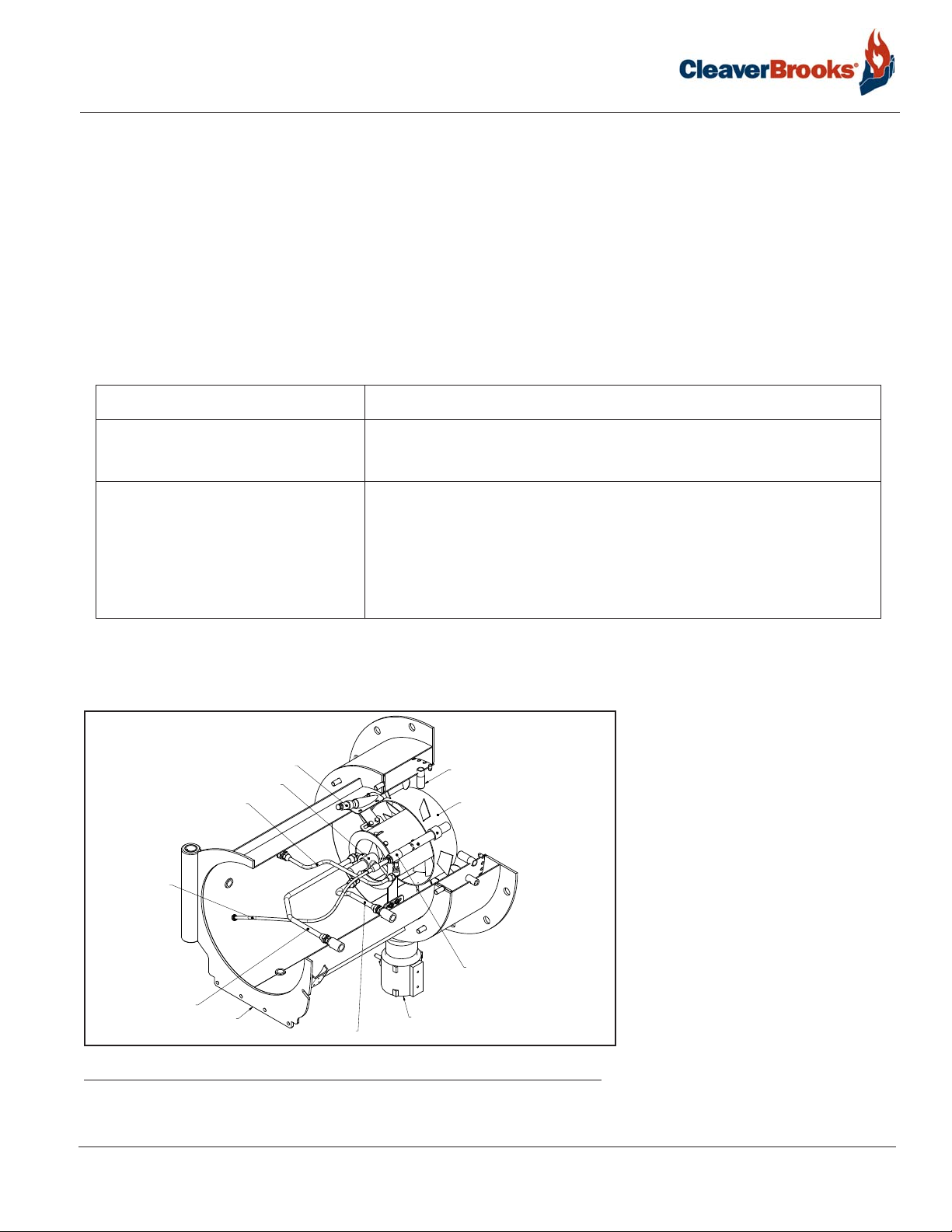
1.5 — Firing Head
AIR ATOMIZING OIL NOZZLE ASSEMBLY
ELECTRODE LEAD
ATOMIZING AIR LINE
FIGURE 1-1. Burner Housing
(SINGLE OR DUAL)
GAS PILOT LINE
BURNER HOUSING
FLAME SCANNER
FUEL OIL LINE
GAS INLET
GAS SPUDS
AIR DIFFUSER
GAS PILOT ASSEMBLY
WITH ELECTRIC SPARK IGNITION
Access to the firing head is provided by
swinging open the impeller housing.
First, disconnect the damper linkage,
release the housing latch, and swing the
housing to the open position. An
internal gas pilot is standard on all
burners. Pilot gas pressure is adjusted at
the pilot pressure regulator.
750-297
Profire E/LNE Series Manual
1-3
Page 18
Introduction
1.6 — Oil System Air Atomizing
E Model burners use compressed air for atomization. Atomizing air is independent of combustion air. The system is
supplied with a separate compressor module for mounting near the burner.
1.6.1 — 3-Way Solenoid Valve
Metered oil enters the common port of the 3-way solenoid valve. During shutdown, pre- and post-purge, the valve is
de-energized (N.C. port closed) and all metered fuel oil returns to the storage tank. When the valve is energized,
metered oil is directed to the nozzle through the N.C. port.
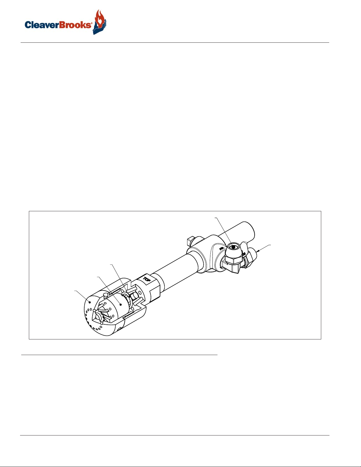
1.6.2 — Nozzle Assembly
The nozzle assembly consists of four main parts: body, compression spring, swirler, and tip. The swirler is held against
the nozzle tip by the compression spring. The nozzle body has inlet ports for air and oil lines. Metered fuel oil enters
the nozzle body and flows through a tube to the swirler. Oil is forced from the core of the swirler to the side ports where
it meets with the atomizing air. Atomizing air enters and passes through the nozzle body to grooves in the swirler,
where it mixes with fuel oil. Air/oil passes through grooves and out of the nozzle orifice in a cone of atomized oil.
Proper velocity and angle of the fine spray ensures good mixing with the combustion air, providing quiet starts and
excellent combustion efficiency. During pre- and post-purge, the nozzle tip is purged with air. This prevents afterdrip or
baked-on residue.
SPRING
SWIRLER
NOZZLE TIP
FIGURE 1-2. Nozzle Assembly
1.6.3 — Oil Strainer
Prevents foreign matter from entering the burner oil system.
ATOMIZING AIR
FUEL OIL
1.6.4 — Atomizing Air Proving Switch
Pressure actuated switch contacts close when sufficient atomizing air pressure is present. The oil valve will not open
unless switch contacts are closed.
1-4
Profire E/LNE Series Manual
750-297
Page 19

Introduction
1.6.5 — Oil Metering
Fuel oil under nominal pressure in the circulating loop flows to the adjustable positive displacement (volumetric
metering unit). Oil metering is accomplished by changing the piston stroke by means of an eccentric shaft and pin
assembly. The pistons reciprocate in a rotor assembly, turning in a hardened steel sleeve having oil inlet and discharge
slots. During each revolution the pistons go through the following cycle:
1. Inlet Cycle. The piston is at the bottom dead center position. At this position, the cavity between the top of the
piston and the outside diameter of the rotor fills with oil.
2. Discharge Cycle. (180º from inlet cycle) The piston is at the top dead center position. At this position, the oil is
forced out of the discharge port to the nozzle. The piston stroke length is determined by the position of the eccentric
shaft and plate. The piston adjustment plate is positioned by an adjustable eccentric shaft. The eccentric shaft is
positioned by the modulator through adjustable linkage. Counterclockwise rotation of the eccentric shaft increases
the piston stroke (more oil delivered to nozzle); clockwise rotation decreases the amount of oil delivered. When the
eccentric shaft is stationary, at any position, the stroke of the pistons remains constant delivering a constant volume
of oil regardless of viscosity.
1.6.6 — Separate Compressor Module
EL and ELG burners have a burner mounted oil metering unit and a separate compressor module. The system functions
as follows:
Air is supplied by a positive displacement rotary vane compressor. This provides a constant volume of atomizing air
regardless of pressure. The compressor module includes motor , air-oil reservoir tank, air filter, and lube oil cooling coil.
Air enters the compressor through the filter. The air flows from the compressor into the air-oil separating and reservoir
tank. Filtering material and baffles separate the lube oil from the compressed air. The tank air pressure forces
lubricating oil from the tank to the compressor to lubricate bearings and vanes. A sight glass indicates the level of
lubricating oil in the air/oil reservoir. Lubricating oil must be visible in the gauge glass at all times. Air compression
heat is absorbed in part by the flow of lube oil, creating a hot oil mist. The air/oil mist is cooled by a coil assembly.
Lube oil is also cooled before entering the compressor.
Fuel is delivered to the positive displacement metering pump at 10 to 15 psi. Metered oil is delivered to the common
port of a 3-way solenoid valve for transfer to the burner nozzle through the normally closed port or back to the storage
tank through the normally open port. During pre- and post-purge, metered oil is returned to the tank. During normal
firing, all metered oil is delivered to the nozzle. For the description of typical fuel oil piping installations, see Chapter 2.
Air enters a rotary vane compressor through an air cleaner where it is compressed to atomizing pressure. Air flows from
the compressor to an air/oil tank which serves the multiple purpose of dampening air pulsation, lube oil mist recovery,
lube oil and atomizing air storage. The compressor rotor is cooled and lubricated continuously by oil under pressure
from the air/oil tank. Oil vapor is extracted by a mist eliminator in the upper section of the tank. Atomizing air from the
upper tank section is delivered to the nozzle at a constant volume. Air pressure increases as the burner firing rate
increases. Atomizing pressure may be adjusted by the needle valve located on the air-oil pump. The valve allows air to
be bled from the tank to the compressor inlet. Delivery rate of the fuel oil metering pump is controlled by the
modulating motor through adjustable linkage.
750-297
Profire E/LNE Series Manual
1-5
Page 20
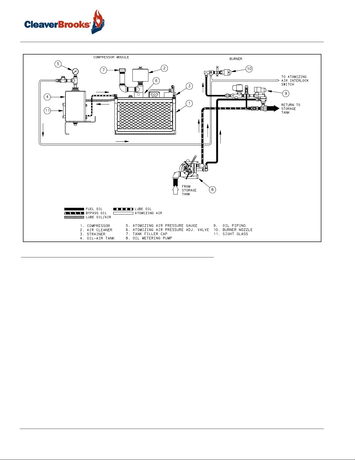
Introduction
FIGURE 1-3. Compressor Module and Burner
1.7 — Gas System
Gas is introduced into the combustion zone from a circular manifold through multiple ports in the manifold. Firing rate
is determined by the size and number of ports, by manifold pressure, and by combustion zone pressure. The firing rate
is regulated by a rotary, butterfly-type throttling valve at the manifold inlet. The valve is actuated by an adjustable
linkage from the modulating motor. Depending upon specific requirements, one or two safety shutoff motorized main
gas valves are provided for installation in the gas train upstream of the butterfly valve. Safety shutoff gas valves are
wired into the programming control to automatically open and close at the proper time in the operating sequence.
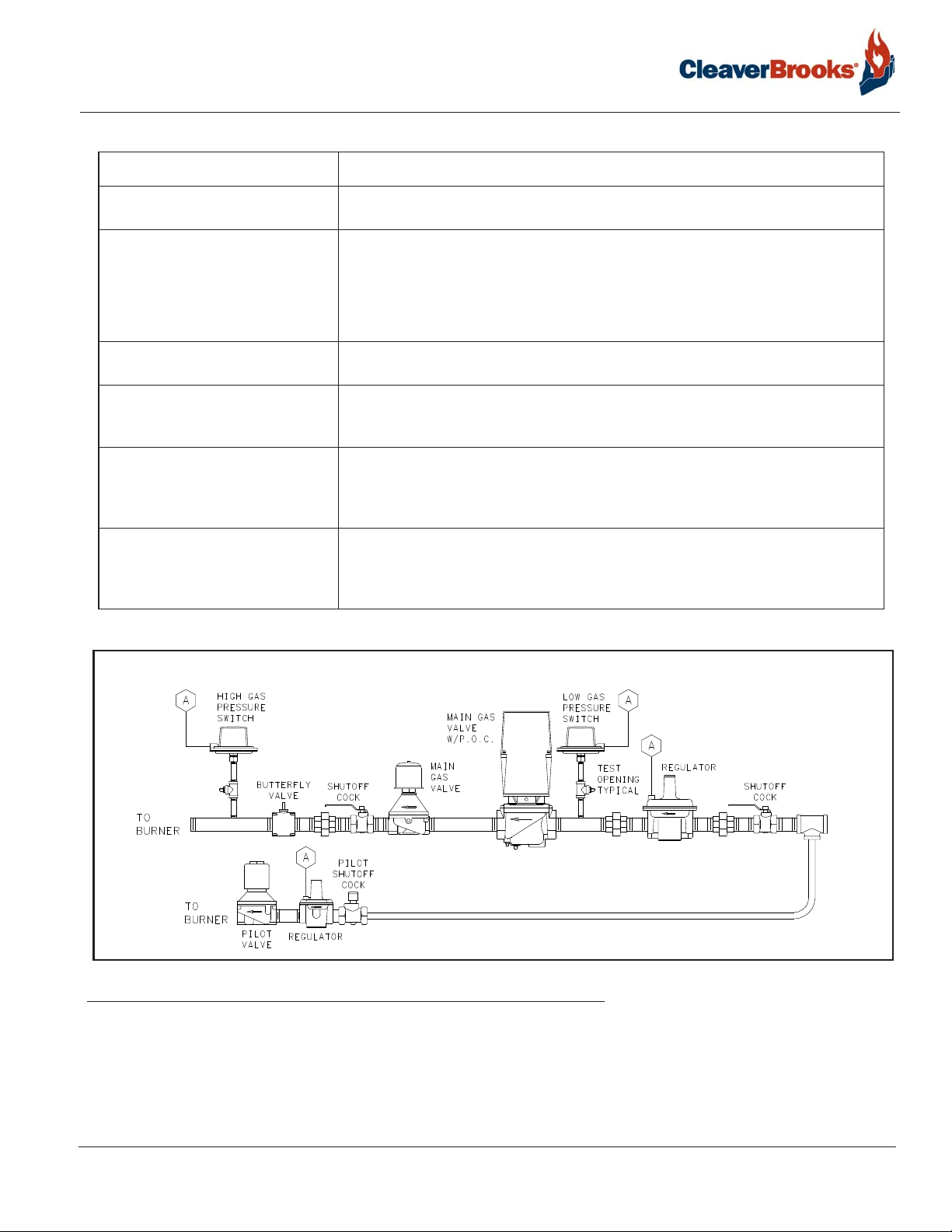
1.7.1 — Main Gas Train Components
Depending upon the requirements of the regulating authority , the gas control system and gas train may consist of some,
or all, of the following items:
1-6
750-297
Profire E/LNE Series Manual
Page 21
Introduction
Component Description
Gas Volume Valve The butterfly-type valve is positioned by linkage from the modulating motor and
controls the rate of flow of the gas.
Main Gas Valves Electrically operated safety shutoff valve(s) that open to admit gas to the burner.
Standard U.L. burners include:
• Models E84-105: One motorized gas valve w/closure interlock and one solenoid
valve.
• Models E126-630: Two motorized gas valves, one w/closure interlock.
Main Gas Regulator Regulates gas train pressure to specified pressure required at inlet to the gas train.
Input is set my the main gas pressure regulator adjustment.
Main Gas Cocks For manual shutoff of the gas supply upstream of the pressure regulator. A second
shutoff cock downstream of the main gas valve(s) provides a means of testing for
leakage through the gas valve(s).
High Gas Pressure Switch A pressure actuated switch that remains closed when gas pressure is below a pre-
selected setting. Should the pressure rise above the setting, the switch contacts will
open causing main gas valve(s) to close. This switch requires manual reset after
being tripped.
Low Gas Pressure Switch A pressure actuated switch that remains closed when gas pressure is above a pre-
selected setting. Should the pressure drop below this setting, the switch contacts will
open, causing main gas valve(s) to close. This switch requires manual reset after
being tripped.
FIGURE 1-4. Main Gas Train (Model E84 - E105)
750-297
Profire E/LNE Series Manual
1-7
Page 22
Introduction
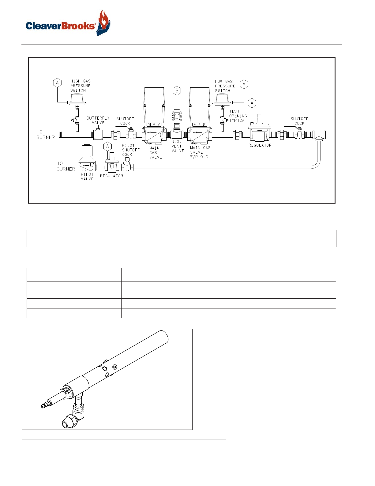
FIGURE 1-5. Main Gas Train (Model E126-E420)
NOTE: These piping layouts are for reference only and are subject to change without notice. Optional equipment may
change a layout.
1.7.2 — Pilot Gas Train Components
Component Description
Gas Pilot Valve A solenoid valve that opens during the ignition period to admit fuel to the pilot. It
closes after main flame is established.
Gas Pressure Regulator Reduces gas pressure to that required by the pilot.
Gas Pilot Shutoff Cock For manually closing the pilot gas supply.
FIGURE 1-6. Gas Pilot
1-8
750-297
Profire E/LNE Series Manual
Page 23

Introduction
1.7.3 — Operation
Metered gas flows through the main gas shutoff cock, through the pressure regulator to the automatic gas valves and
butterfly valve to the gas manifold.
The butterfly gas valve modulates flow to burner input demand. The butterfly valve is positioned through mechanical
linkage by the modulating motor. The air control damper is positioned simultaneously by the modulating motor.
The automatic gas valve(s) cannot be energized unless the combustion air proving switch is closed. The low and high
gas pressure switches must be closed to prove proper gas pressure.
A normally open vent valve, if required, is located between the two automatic gas valves. This valve is shut when the
automatic gas valves are open. When the automatic valves are closed, the vent valve is open for venting gas to the
outside, should any be present.
750-297
Profire E/LNE Series Manual
1-9
Page 24

Introduction
1-10
750-297
Profire E/LNE Series Manual
Page 25

CHAPTER 2 Installation
2.1 — Application
Electrical power available is usually 208 volt, 3-phase, 60 cycle, 230/460 volt, 3-phase, 60 cycle or 380 volt,
3-phase, 50 cycle. Control circuit is 115 volt, single phase, 60 cycle or 115 volt, single phase, 50 cycle. Refer
to the electrical schematic diagram shipped with the burner. Power connections are made at the control panel.
Wiring from the panel to burner mounted components is installed at the factory. Wiring from the burner panel to
boiler controls, low water controls, remote compressor motor, and remotely located fuel valves is furnished by the
installer.
2.2 — Draft Conditions
Automatic over-fire draft control or barometric draft regulators are not usually required except where the system
has a tall chimney. The exact height of a chimney requiring draft control is indeterminate, but draft regulation is
seldom needed for chimneys less than 50 feet high, especially with Scotch Marine or sealed firebox boilers.
750-297
Profire E/LNE Series Manual
2-1
Page 26
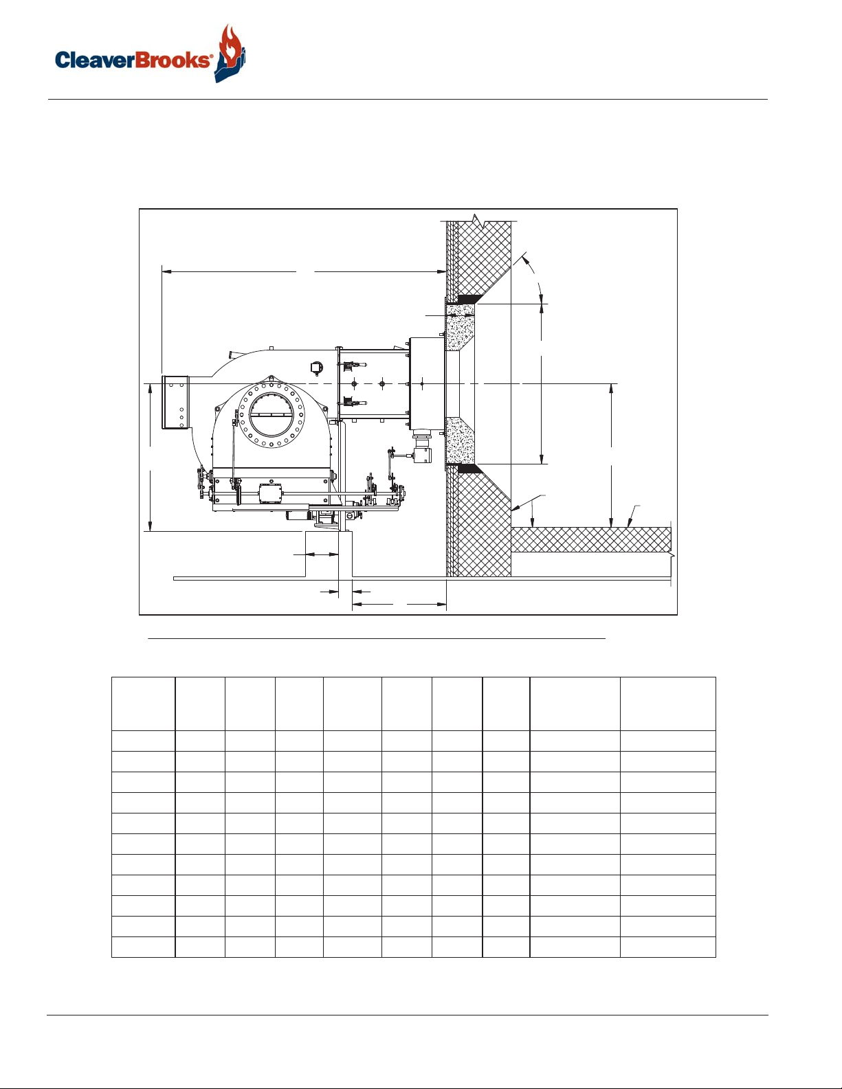
2.3 — Combustion Chamber Recommendations and E Refractory Dimensions
The combustion chamber dimensions should be proportioned to the heating load of the boiler.
2.3.1 - Watertube Boiler Dimensions
Installation
E
45°
A
B
BURNER
C
L
D
STANDARD
FIREBRICK
1-1/2" + A
F
BLOCK INSULATION
C (MIN)
FLOOR
G
FIGURE 2-1. Combustion Chamber Dimensions (Watertube Boiler)
2-2
Burner
Size A B C D E F G
84 10 19 19 31.5* 64 3.5 23 38 74
105 10 19 23 31.5* 64 3.5 23 46 84
126 10 19 24 31.5* 64 3.5 23 50 90
147 12 22 25 31.5* 64 3.5 23 55 100
168 12 27.5 27 37* 78 3.5 31 60 108
210 12 27.5 30 37* 78 3.5 31 70 120
252 15 31.5 30 37* 78 3.5 31 84 132
294 15 31.5 32 42* 87 3.5 33 84 144
336 18 34.6 34 42* 87 3.5 33 86 152
378 18 34.6 36 42* 87 3.5 33 92 160
420 18 34.6 38 42* 87 3.5 33 96 170
* Dimension is for oil applications. Dimension will be less for gas only applications.
Combustion
Chamber
Min. Width
Combustion
Chamber Min.
Length
Profire E/LNE Series Manual
750-297
Page 27

Installation
2.3.2 - Firetube Boiler Dimensions
FIGURE 2-2. Combustion Chamber Dimensions (Firetube Boiler)
Burner Model Boiler HP A B
84 200 34 115
105 250 34 144
126 300 38 158
147 350 38 185
168 400 42 155
210 500 42 195
252 600 46 194
294 700 48 204
336 800 50 230
378 900 60 230
420 1000 60 230
750-297
Profire E/LNE Series Manual
2-3
Page 28

Installation
(
Q
(
(
Q
19.25)
Q
27.63)
29.13)
Q
.6912X
SIZE 1
A
Q
A
13.39
(45°)8X
(30°)12X
(30°)12X
(15°)
29.75)
(
Q
(Q24.00)
SEE FIGURE 2-4
SIZE 1SIZE 2SIZE 3
SIZE 2 SIZE 3
Q
(
(Q28.25)
A
33.25)
A
A
(30°)12X
(Q31.50)
Q
.6912X
16.00
Q
A
(45°)8X
F
G
E
H
Q
19.00
(22.5°)16X
Q
.8116X
A 25.39 28 31
B 21.39 24 27
C2.812 2
D222
E 0.38 0.38 0.38
F 7.25 7.25 7.25
G 3 4.25 4
H 0.25 0.25 0.25
I 1.63 1.63 1.63
J444
K222
FIGURE 2-3. E-Series Refractory Dimensions
45°
C
B
A
J
I
K
D
90°
SECTION A-A
2-4
750-297
Profire E/LNE Series Manual
Page 29

Installation
2.4 — Installation
Caution
!
The housing must be supported when in the open position to prevent damage to the hinges and other components.
Caution
!
The heat exchanger may have areas within the furnace susceptible to heat damage and may require furnace liner tile
and refractory cement filler to adequately protect those surfaces. Specific installation requirements for such
circumstances are beyond the scope of this manual.
2.4.1 - General
The installer will need asbestos-free high-temperature-rope gasket, ceramic fiber blanket (e.g. Kaowool, Cerafelt),
tack spray and masking tape not provided with the burner.
Proper burner operation requires the burner to be installed so that the burner and blast tube are level.
For maximum safety, mating surfaces between the heat exchanger, dry oven and burner must be sealed to
prevent escape of combustion products into the boiler room.
Do not rely on the boiler front plate to fully support the burner. Securely support the burner pedestal to stable
flooring. The factory provides a nominal length burner support leg but variations in job-site floor heights may
require additional support to the reach the floor (see Figure 2-1).
Provide enough clearance in the burner mounting area to allow the burner housing to hinge fully open for service
and maintenance.
2.4.2 - Refractory Dry Oven
Caution
!
For firetube applications:
(a)A dry oven built for a specific application shall have an outer diameter ½" less than the firetube's interior diameter
(Figure 2-3 dim "A"). This gap is required for the soft pack described later in the dry oven installation section.
(b)The firetube must be thermally protected at least 2.5 inches beyond the tube sheet.
The burner may have been purchased with either a custom refractory dry oven sized for a specific heat exchanger
or a standard refractory dry oven sized per Figure 2-3. If a refractory dry oven was not purchased with the burner,
the installer must provide one.
The dry oven provides an initial combustion area required for flame stability so a third-party refractory must
follow the dimensional requirements of Figure 2-3. Scaling the Figure 2-3 outer diameter dimension "A" and
depth dimension "F" is allowed to best fit a specific heat exchanger.
750-297
Profire E/LNE Series Manual
2-5
Page 30

Installation
When retrofitting a heat exchanger, if a flame-shaping dry oven was used with the previous burner, discard that
dry oven.
Dry Oven Installation:
The face of the boiler and refractory dry oven flange must be sealed with asbestos-free ceramic fiber blanket or
rope gasket to prevent emission-gas leakage.
Firetube installation requires the space between the dry oven's outer diameter and the firetube's furnace diameter
to be soft packed as follows:
• Apply tack spray to the outer circumference of the refractory dry oven to help hold ceramic fiber blanket in
place.
• Wrap the outer diameter of the dry oven with ceramic fiber blanket while leaving a 1" space from the dry
oven's front edge to the blanket wrap. The wrap must fill the gap between the refractory outside diameter and
the firetube's internal diameter. The 1" recess keeps the blanket edge from eroding.
• Use masking tape to both secure and compress the ceramic fiber blanket around the dry oven. The wrapped
ceramic fiber blanket must provide a snug fit between the dry oven and the heat exchanger. If necessary,
rework to fill voids in this gap.
• Remove excess ceramic fiber blanket.
FIGURE 2-4. Dry Oven Detail
Burner to boiler-mounted dry oven installation:
• Make sure the dry oven and burner blast tube are concentric.
• The burner flange must be sealed to prevent emission gas leakage. To seal the flange, use the provided flange
gasket or ceramic fiber blanket trimmed to fit.
2-6
Profire E/LNE Series Manual
750-297
Page 31

Installation
2.5 — Separate Compressor Module
For oil burners supplied with a separate compressor module, piping to the burner is installed. Earlier models have
the oil cooler finned coil located below the damper. The earliest units used a coil in the blast tube, but piping to
the compressor and tank is essentially similar. Copper tubing for the installation is not supplied with the burner.
FIGURE 2-5. Separate Compressor Module
2.6 — Typical Oil Supply Loop
Continuous oil circulation must be supplied to the burner at a rate of 50 percent greater than the high fire
burning rate. The oil circulating pump should be located as close as possible to the storage tank to keep suction
lines short and minimize suction loss. Pipe line sizes indicated on the following oil piping schematics are of
ample size to reduce pressure losses. If heating of the fuel oil is required, the lines must be large enough to
prevent restriction of flow through any cold spots in the system. Note that the supply line is approximately 20
inches or higher above the burner metering pump inlet to help eliminate air problems. Above that is an
adjustable, spring-loaded back pressure valve that sets approximately 10 to 15 PSI on the circulating loop. The
return line to the tank is connected at the discharge port of the back pressure valve. Since air rises to the highest
point, it will rise from the supply entrance and pass through the back pressure valve to the return line and on to
the tank. Metered oil is pumped (by the metering pump) to the common port of a 3-way valve. With the 3-way
valve de-energized, the metered oil returns to the tank through the back pressure valve and return line. When the
3-way valve is energized, metered oil is passed on to the burner oil nozzle and atomized by air from the
compressor. The proper strainers, check valves, vacuum, and pressure gauges, etc. should be installed as
indicated. All lines should be pressure tested after installation.
750-297
Profire E/LNE Series Manual
2-7
Page 32

Installation
FIGURE 2-6. Typical Oil Supply Loop
2.7 — Oil Circulating Loop Operation
An oil circulating pump provides continuous oil circulation to the circulation loop. A back pressure valve holds
10 to 15 psi on the loop system. With the oil supply line connected only to the oil metering pump inlet, all oil
must pass through the pump. During pre-purge, unmetered oil flows through a bypass section of the oil metering
pump. Metered oil passes through the metering section to a de-energized 3-way oil valve (common port). Both
unmetered and metered oil must pass through the back pressure valve and return to an oil storage tank. The oil
metering pump will only meter oil. It will not serve as a circulating pump. At trial for main flame (main fuel), the
3-way oil valve is energized admitting metered oil to the nozzle for atomization and fast smooth ignition.
Unmetered oil continues to flow through the bypass section of the oil metering pump and returns to an oil
storage tank.
2-8
Profire E/LNE Series Manual
750-297
Page 33

Installation
TO DRAWER
ASSEMBLY
REQUIRED IF PUMP DOES NOT
HAVE AN INTERNAL RELIEF.
RELIEF VALVE SET AT 50 PSI
GATE
VALVE
STRAINER
RETURN
SUCTION
2-WAY VALVE
ON BURNER
VACUUM
GAUGE
CHECK
VALVE
GATE
VALVE
RELIEF
VALVE
PRESSURE
GAUGE &
NEEDLE
VALVE
GATE
VALVE
GATE
VALVE
3-WAY VALVE
ON BURNER
CHECK
VALVE
OIL METERING
PUMP (SUPPLIED
WITH BURNER)
STRAINER
BACK PRESSURE VALVE
SET AT 10-15 PSI
LOW OIL
PRESSURE
SWITCH
OIL
STORAGE
TANK
TANK TO CIRCULATING PUMP CIRC. PUMP TO BURNER & RETURN
EL, LNEL EL, LNEL
2” 1 1/2”
84, 105, 126, 147, 168, 210
THIS PIPING LAYOUT IS FOR REFERENCE ONLY
AND IS SUBJECT TO CHANGE WITHOUT NOTICE.
OPTIONAL EQUIPMENT MAY CHANGE THIS LAYOUT
FIGURE 2-7. No. 2 Oil Loop E-84 — E-210
OIL
CIRCULATING
PUMP
NO. 2 OIL
RECOMMENDED PIPE SIZE
PIPING BY OTHERS
PIPING BY I.C.
84, 105, 126, 147, 168, 210
750-297
Profire E/LNE Series Manual
2-9
Page 34

REQUIRED IF PUMP DOES NOT
HAVE AN INTERNAL RELIEF.
RELIEF VALVE SET AT 50 PSI
GATE
VALVE
STRAINER
RETURN
SUCTION
TO DRAWER
ASSEMBLY
VACUUM
GAUGE
CHECK
VALVE
GATE
VALVE
2-WAY VALVE
ON BURNER
PRESSURE
GAUGE &
NEEDLE
VALVE
RELIEF
VALVE
GATE
VALVE
GATE
VALVE
Installation
BACK PRESSURE VALVE
SET AT 10-15 PSI
3-WAY VALVE
ON BURNER
LOW OIL
PRESSURE
SWITCH
CHECK
VALVE
OIL METERING
PUMP (SUPPLIED
WITH BURNER)
STRAINER
OIL
STORAGE
TANK
TANK TO CIRCULATING PUMP CIRC. PUMP TO BURNER & RETURN
EL, LNEL EL, LNEL
2” 1 1/2”
252, 294, 336, 378, 420
THIS PIPING LAYOUT IS FOR REFERENCE ONLY
AND IS SUBJECT TO CHANGE WITHOUT NOTICE.
OPTIONAL EQUIPMENT MAY CHANGE THIS LAYOUT
FIGURE 2-8. No. 2 Oil Loop E-252 — E-420
2-10
OIL
CIRCULATING
PUMP
NO. 2 OIL
RECOMMENDED PIPE SIZE
PIPING BY OTHERS
PIPING BY I.C.
252, 294, 336, 378, 420
750-297
Profire E/LNE Series Manual
Page 35

Installation
2.8 — Circulating Oil Pump
A circulating oil pump is required to deliver fuel oil from the storage tank to the burner at a minimum of 150% of
the maximum burner firing rate. The excess oil allows a margin for piping error, viscosity changes in the fuel oil,
and circulating pump wear. Correct pipe sizing is determined by circulating rate, not burner capacity. Install the
pump as close to the supply tanks as possible. Suction lift should be as low as possible. Maximum suction of 15"
Hg vacuum is good practice for either light or heated heavy oil. The strainer should be installed in the suction line
just ahead of the circulating pump to prevent foreign material from entering the pump. Locate the strainer so it
may be easily cleaned.
2.9 — Back Pressure Valve
A back pressure valve, similar to Watson McDaniel type "R," needs to be installed on the return line. This valve
must be installed in an upright vertical position. Before installing the valve, be sure to blow out the pipe line,
removing all dirt, pipe scale and sediment. This type of valve is actuated by the system pressure which enters the
body beneath the main valve. Valve loading is provided by a spring that can be adjusted to the desired set
pressure.
To adjust the set pressure, remove the top cap, loosen the brass locknut and adjust the pressure with the steel
setscrew. By increasing the compression on the spring, screwing down the screw, you increase the set pressure
within the limits of the spring range. Reversing the setscrew lowers the set pressure.
Adjust to 10-15 PSI for No.2 oil systems. When the desired pressure is reached, tighten the locknut and replace
the top cap and gasket.
2.10 — Gas Piping
Refer to Figures 1-4 and 1-5 for typical gas train piping.
Gas service and house piping must supply the quantity of gas demanded by the unit at the pressure required at
the burner gas train inlet. All piping must be in strict accordance with applicable codes, ordinances, and
regulations of the supplying utility. In the absence of other codes, piping should be in accordance with the
following standards: "National Fuel Gas Code" NFPA No. 54, ANSI No. Z 223.1 (for Canada, the Canadian Gas
Association (CGA) B149 and Canadian Standards Association (CSA) B140 codes shall prevail).
Gas train components upstream of the butterfly valve are shipped loose. These components should be mounted
by the installer as close to the butterfly valve as practical. Normally, the control train is ordered to suit a
particular code or insurance regulation, such as Underwriters Laboratories Inc., CGA, or Factory Mutual.
Arrange gas piping at the burner so that the burner is accessible for servicing without disassembly.
The gas pilot supply line must be connected upstream of the main gas regulator. If a reducing bushing is required
between the house piping and the burner piping, it should be close to the burner shut-off valve.
The gas piping must be internally clean and free of foreign material. Before using in service, a leak test must be
performed.
750-297
Profire E/LNE Series Manual
2-11
Page 36

Installation
2.11 — Installation Checklist
All burners are carefully assembled and tested at the factory, but before being placed in service, all connectors
should again be checked for looseness caused during shipment.
Check:
• Electrical terminals in the control panel and on all electrical components.
• Pipe fittings and unions.
• Tubing connections.
• Nuts, bolts, screws.
Before operating pumps, metering heads and compressors, make certain that reservoirs are properly filled with
the specific lubricant. Open all necessary oil shut-off valves. Do not run compressors, pumps, or metering units
without oil.
Before connecting electrical current to any component, be sure the supply voltage is the same as that specified
on component nameplates.
Before burner operation, be sure all motors are rotating in the correct direction.
Before firing, make sure that the refractory flame cone is properly sealed to the burner mounting flange and the
boiler front plate.
Make certain that the operator in charge is properly instructed in the operation and maintenance procedures.
Caution
!
Before opening the gas shutoff valves, read the regulator instructions carefully. Open the shutoff valve slowly to allow
inlet pressure to build up slowly in the regulator until it is fully pressurized. Opening the shutoff valve quickly will
damage the regulator.
Do not exceed the regulator pressure ratings.
Caution
!
Lubricating oil is drained from the air/oil tank before shipment. Before attempting to start the burner, add oil to the
recommended level.
2-12
750-297
Profire E/LNE Series Manual
Page 37

CHAPTER 3 Operation
3.1 — Preparations for Starting
When the installation is complete and all electrical, fuel, water, and vent stack connections are made, make certain said
connections are tight. The operator should become familiar with the burner, boiler controls, and components. To
identify controls and components, refer to contents of Chapter 1. Adjustment procedures given in Chapter 4 should be
reviewed prior to firing. The wiring diagram should also be studied along with the operating sequence of burner
programmer. Read and understand starting instructions before attempting to operate the burner. Before attempting to
start the burner, the following checks must be made:
Item Check
Boiler Check the boiler water level. Be sure all boiler valves are installed correctly and positioned
properly. Set the high limit control slightly above the desired temperature. Set modulating
controls at the desired temperature or pressure.
Burner Check the electrical power supply to the burner in accordance with the nameplate voltage on all
motors and the control circuit. Check the direction or rotation of the motors. Open the housing
to check the electrode setting. Check the gas pilot pressure at the pilot gas regulator. The
normal setting is 3” to 6” W.C.
For protection in shipment, the flame safeguard control chassis is shipped unmounted. Check
all screw connections before attaching the flame safeguard chassis to the base. The screw must
be secure to assure low resistance connections. The relay chassis is mounted on the sub-base
with a screw which, when tightened, completes the connection between the sub-base and
chassis contacts. Press the manual reset button to be sure safety switch contacts are closed.
Check the control linkage for proper movement of the air volume damper and fuel metering
components. This can be done by loosening the linkage at the actuator level and manipulating
by hand.
Check the air shutter and adjust low fire setting.
Oil-Air Tank (Lube Oil) Check the lube oil level in the air-oil tank. Inspect oil level regularly. Loss of oil will damage
the compressor. Fill the tank with non deter gent SAE30 oil to a level midway up the sight glass.
Do not overfill the tank.
For a normal environment use SAE10 oil. Change oil every 2000 hours of operations.
750-297
Profire E/LNE Series Manual
3-1
Page 38

Operation
3.1.1 — Oil Flow
Refer to piping diagrams. Open all valves in the oil suction and return line. The burner oil metering units are not
capable of creating suction. Fuel oil must be supplied to the metering unit at a nominal 10 to 15 psi pressure by a
circulating supply pump.
3.1.2 — Oil Pressure
The system pressure is regulated by the back pressure valve. This should be set between 10 to 15 psi at the burner inlet
after the temperature stabilizes.
3.1.3 — Firing Preparations for Oil Burners
Prior to initial firing, oil flow pressure and temperature should be verified.
Inspect the compressor lube oil sump level. Add oil to bring the oil level to the midpoint or slightly higher in the
reservoir sight glass.
Make certain that the drive belts or couplings are aligned and properly adjusted.
To verify air flow and pressure, momentarily flip the switch “ON” and immediately turn “OFF.” The programmer will
continue through its cycle, however, without ignition or energizing the fuel valves. Observe the air pressure gauge.
With the compressor running and no oil flow, the pressure should be approximately 10 psi. The schematic flow
diagrams in Chapter 1 indicate the flow of fuel and atomizing air.
If the burner is a dual fuel model, make certain that the main gas shutoff cock is closed and the fuel selector switch is
set to “OIL.”
3.1.4 — Firing Preparations for Gas Burners
A representative of the gas utility should turn on the gas. Determine by a test gauge upstream of the burner regulator
that sufficient pressure exists at the entrance to the gas train. The gas pressure regulator must be adjusted to the pressure
required and the pressure setting recorded.
On combination fuel models, set the selector switch to “GAS.” On initial startup, it is recommended that the main gas
shutoff cock remain closed until the programmer has cycled through pre-purge and pilot sequences to determine that
the main gas valve opens. Turn the burner switch “OFF” and let the programmer finish its cycle. Check to see that the
gas valve closes tightly. Set the high and low gas pressure switches.
Check for leaks and determine there is adequate gas pressure available at the burner for operating at full capacity.
Check with the local utility if necessary. Check gas pressure at the pilot and the main burner. Close the manual gas
valve.
3.2 — Electrical Interference Test
Prior to putting the burner into service, conduct the following test to ascertain that the ignition spark will not cause the
flame relay to pull in.
3-2
Profire E/LNE Series Manual
750-297
Page 39

Operation
3.2.1 — Gas Fired
1. Close the pilot and the main line manual gas valves.
2. Start the burner and at the time of the pilot trial, with just the electrical ignition system energized, the flame relay
should not pull in (be energized).
3. Upon completion of successful test, proceed with startup procedures.
3.2.2 — Oil Fired
1. Disconnect the electrical power to the burner.
2. Disconnect the electric oil safety shutoff valve.
3. Reconnect electric power to the burner.
4. Close the pilot line manual gas valve, if used.
5. Start the burner and at the time of the pilot trial, with just the electrical system energized, the flame relay should not
pull in.
6. Upon completion of successful test, disconnect the power supply,
7. Reconnect oil safety shutoff valve and turn on manual pilot gas valve.
8. Reconnect power supply and proceed with startup procedures.
3.3 — Gas Pilot Flame Adjustment
The gas pilot flame is regulated by adjusting the pressure setting of the pilot regulator. Normal setting is 3" to 6" W.C.
when the pilot is burning. The flame must be sufficient to be proven by the flame detector and ignite the main flame.
Although it is possible to visibly adjust the size of the pilot flame, obtain a proper DC volt or microamp reading of the
flame signal.
The flame safeguard amplifier has a meter jack for this purpose. At initial startup and during planned maintenance, test
the pilot flame signal, pilot turndown, and safety switch lockout.
3.4 — Startup Sequence
The programming control sequences the operation of all controls and components through the starting, ignition, firing,
and shutdown cycle. The burner and control system are in starting condition when:
• The operating and high limit control (temperature or pressure) are below their cutoff setting.
• All power supply switches are closed.
• Power is present at the control panel.
Refer to the manufacturer’s literature on programming controls and burner wiring diagrams for detailed information.
1. Begin starting sequence, with burner switch off, and with all manual valves closed. Switch main power on.
2. When firing oil, open the manual oil valves.
3. When firing on gas, open the main manual gas valve.
4. When firing on gas, manually reset the high and low gas pressure switches.
750-297
Profire E/LNE Series Manual
3-3
Page 40

Operation
5. Place the gas.oil selector switch in position for the desired fuel. W ith all limit and operating controls calling for heat,
the burner will follow the Flame Safeguard Sequence.
6. When the burner motor starts, open the gas cock.
7. If firing on gas, when the main fuel lamp lights indicating pilot flame proven, slowly open the second shutoff cock
downstream of the main gas valve(s).
Refer to the manufacturer’s literature on primary control sequence of operations.
3.5 — Automatic Shutdown
Limit or operating controls open:
1. Fuel valves close. Main fuel lamp goes off. Flame safeguard timer starts.
2. Flame safeguard timer and burner motor stop. Burner is ready for startup on the next call for heat.
3.6 — Manual Shutdown
1. Turn gas/oil selector switch off. The burner shuts down in Automatic Shutdown as above.
2. When the burner motor stops, close all manual valves.
3.7 — Safety Shutdown
1. If at any time during the operating cycle a flame failure occurs, the burner shuts down as in Automatic Shutdown,
with an additional post-purge, and the flame failure lamp is energized.
Warning
!
Read the Flame Safeguard manual and fully understand its contents before attempting to operate this equipment. If the
manual is not read and understood, serious personal injury or death may result.
Warning
!
Should a starting failure occur for any reason, combustible fumes may fill the combustion chamber. Never attempt to relight the burner under these conditions. The combustion chamber must first be purged before re-lighting.
Warning
!
Keep fingers away from the combustion air intake below the damper. The damper is actuated with sufficient force to cause
severe injury. Always make high and intermediate rate adjustments when the burner has reached low fire position. Do not
disturb the low fire setting.
A. The lockout switch on the flame safeguard control must be manually reset before the burner will fire again.
3-4
Profire E/LNE Series Manual
750-297
Page 41

Operation
2. If a low water condition occurs, the burner shuts down as in Automatic Shutdown.
3. If a high or low gas pressure condition occurs while firing on gas, the burner shuts down as in Automatic Shutdown.
A. Condition must be corrected and the respective gas pressure switch manually reset before the burner will fire
again on gas.
3.8 — Startup and Operating
3.8.1 — Gas Burners
1. Close the main and pilot gas cocks.
2. Make sure the ON-OFF switch is in the “OFF” position and the fuel selector switch is turned to “GAS.”
3. Actuate the manual reset button of the flame safeguard control to close the safety switch contacts.
4. Set the MANUAL-AUTO switch in the “MANUAL” position.
5. Set the manual potentiometer in the low fire position.
6. Open the gas pilot cock.
7. Set the ON-OFF switch to “ON.” The burner will start and pre-purge. After pre-purge, the ignition transformer and
the gas pilot solenoid are energized. Before proceeding, conduct electrical interference and pilot turndown tests if
not previously done (see Section 3.2).
8. On initial startup it is recommended that the main gas shutoff cock remains closed until the programmer has cycled
through pre-purge and pilot sequence. Then determine that the main gas valve opens. When this is confirmed, turn
the burner switch “OFF” and let the programmer finish its cycle.
9. Check to see that the gas valve has closed tightly. If ignition does not occur, turn the burner switch “OFF” and allow
the programmer to recycle for a new ignition trial.
10. Turn the burner “ON” and after pilot ignition when the flame relay pulls in, the slow opening, motorized, main gas
valve is energized. The main flame should ignite at this time. The gas valve and air damper continue advancing until
high fire is reached.
11. Do not repeat unsuccessful light off attempts without rechecking burner and pilot adjustment. Vent fuel vapors from
the combustion chamber after each unsuccessful light off attempt.
12. Set the gas low fire rate by adjusting the butterfly valve and air linkage.
13. When low fire is adjusted, shut down the burner.
14. Restart several times to be sure the low fire setting is suitable. Readjust if necessary. Never start the burner with fuel
vapor in the furnace. In case of an emergency, open the main power switches and close all fuel valves.
15. After combustion adjustments are satisfactorily set, allow the heating vessel to slowly reach normal operating
pressure or temperature.
16. Turn the potentiometer switch to the high fire position. Check high fire at this point using combustion instruments.
17. Do not disturb established low fire adjustment. Allow the burner to return to low fire position before adjusting high
or intermediate settings.
High fire combustion analysis typically is 9% to 10.5% CO
Sections 3.9 and 3.10.
750-297
Profire E/LNE Series Manual
. When conditions covered above are assured, refer to
2
3-5
Page 42

Operation
3.8.2 — Oil Burners
1. Set the fuel selector switch to “OIL.” On initial startup of a combination burner, it is recommended that oil firing be
adjusted before gas firing. The gas low firing rate is set to match the oil low fire rate.
2. Be sure the ON-OFF switch is in the “OFF” position and the fuel selector switch is on “OIL.”
3. Actuate the manual reset button of the flame safeguard control to close the safety switch contacts.
4. Be sure the MANUAL-AUTO switch in the “MANUAL” position.
5. Set the manual modulating control potentiometer in the “LOW FIRE” position.
6. Open the pilot gas valve (if used).
7. Set the ON-OFF switch to “ON.” The burner will start and pre-purge. After pre-purge, the ignition transformer and
the gas pilot are energized. Before proceeding, conduct electrical interference and pilot turndown tests if not
previously done.
8. Observe the primary atomizing air pressure gauge on the air/oil tank. The gauge reading should be approximately 10
psi during pre-purge.
9. When the pilot flame is proven, the programmer will proceed to the main flame position. Allow the burner to
operate in low fire, to warm the boiler before moving to high fire. Typically, for No. 2 oil, CO
is 8% to 11% at low
2
fire.
10. Turn the manual potentiometer switch to the “HIGH FIRE” position. Check the high fire combustion at this point.
Do not disturb previously established low fire adjustment.
11. Allow the burner to return to the low fire position before adjusting high or intermediate settings. The primary
atomizing air pressure will increase automatically with the oil flow rate. Typically, for No. 2 oil, CO
is 10% to 13%
2
at high fire.
When conditions covered above are assured, refer to Sections 3.9 and 3.10.
3.9 — Normal Operation
Normal operation must be with the MANUAL-AUTO switch set on “AUTO.”
In automatic operation, the operating cycle always proceeds sequentially through pre-purge, pilot ignition, main flame
ignition, run, and post-purge. The length of the purge and ignition trial vary according to the type of programmer used.
During the run cycle, burner input is regulated to the load demand by the modulating pressure or temperature control
on the boiler. The burner will continue to modulate until the operating pressure or temperature is reached.
Programmer control operation should be tested when the burner is initially placed into service, when a control is
replaced, and at scheduled intervals in the maintenance program.
Refer to adjustment procedures and maintenance instruction given in Chapters 4 and 5.
3.10 — Shutdown
When the operating limit control setting is reached or the burner switch is in the “OFF” position, the following
sequence occurs:
3-6
750-297
Profire E/LNE Series Manual
Page 43

Operation
1. The fuel valve(s) de-energize and the flame extinguishes. The blower motor continues running during post-purge.
2. At the end of post-purge, the blower motor is de-energized.
3. The programmer returns to its starting position and stops. The unit is ready to restart.
Abnormal shutdown might result from motor overload, flame outage, low water, current or fuel supply interruption,
combustion or atomizing air pressure below minimum level, tripped circuit breakers, blown fuses, or other interlock
devices. Check for the cause and make the necessary corrections before restarting the burner.
Safety shutdown caused by ignition or flame failure will actuate a red indicator light and energize an audible alarm (if
so equipped). If the programmer has a non-recycling interlock circuit, any interruption in this circuit during the prepurge or firing cycle will cause a safety shutdown. This type of shutdown requires manual reset of the programming
control and must be corrected before operation can be resumed.
Warning
!
An ultraviolet flame sensor electrical spark interference test must be performed after final adjustment. See Section 3.2 in
this chapter for additional information.
750-297
Profire E/LNE Series Manual
3-7
Page 44

Operation
3-8
750-297
Profire E/LNE Series Manual
Page 45

CHAPTER 4 Adjustments
4.1 — Overview
While each burner is tested at the factory for correct operation before shipment, variable conditions such as burning
characteristics of the fuel used and operating load conditions may require further adjustment after installation to assure
maximum operating efficiency.
Prior to placing the boiler into initial service, a complete inspection should be made of all controls, connecting piping,
wiring and all fastenings such as nuts, bolts and setscrews to be sure that no damage or misadjustments occurred during
shipping and installation.
A combustion efficiency analysis made during the initial start-up will help to determine what additional adjustments
are required in a particular installation.
4.2 — Combustion Adjustment on Gas and Oil
Efficient combustion cannot be properly judged by flame appearance, although it may help in making preliminary
settings.
The proper settings of air-fuel ratios must be determined by flue gas analysis. Combustion gas analysis indicates the air
to fuel ratio and the degree of complete combustion. Instruments are available to measure carbon dioxide (CO
oxygen (O
), and carbon monoxide (CO).
2
4.2.1 — Stack Temperature
Net stack temperature is obtained by subtracting the ambient temperature from the flue gas temperature. A high net
stack temperature indicates wasted heat. Stack temperature should be as low as possible without causing flue gas
condensation.
Stack heat loss can be reduced by decreasing either the temperature or the volume of the flue gas, or both. Flue gas
temperature is reduced by improving heat transfer or by reducing excess combustion air. A certain amount of excess air
is necessary to complete combustion. More efficient burners require minimum excess air.
2
),
750-297
Profire E/LNE Series Manual
4-1
Page 46

Adjustments
4.2.2 — Smoke Measurement
Smoke measurements can be made using a variety of different methods. The standards will vary somewhat according
to the equipment used, and instructions accompanying the instrument should be followed.
Smoky combustion can result from:
• Improper air delivery
• Insufficient draft
• Improper fuel viscosity
• Improper fuel-air ratio
• Excessive air leaks in the combustion chamber
• Improper fuel oil temperature
4.2.3 — Gas Adjustments
Low fire combustion analysis typically is 7% to 9% CO
and less than .04% CO (400 ppm). A high fire reading
2
typically is 9% to 10.5% CO2 and less than .04% CO.
4.2.4 — Fuel Oil Adjustments
Adjust for a “clean fire.” Typically for No. 2 oil CO
is 8% to 11% at low fire and 10% to 13% at high fire.
2
4.3 — Electrical Interference Test
Prior to putting the burner into service, conduct the following test to ascertain that ignition spark will not cause the
flame relay to pull in.
4.3.1 — Gas Fired
1. Close the pilot and main line manual gas valves.
2. Start the burner and at time of pilot trial with just the electrical ignition system energized, the flame relay should not
pull in (be energized).
3. Upon completion of successful test, proceed with startup procedures.
4.3.2 — Oil Fired
1. Disconnect the electrical power to the burner.
2. Disconnect the electric oil safety shutoff valve.
3. Reconnect electric power.
4. Close the pilot line manual gas valve, if used.
5. Start the burner and at the time of pilot trial, with just the electrical ignition system energized, the flame relay should
not pull in.
6. Upon completion of successful test, disconnect the power supply.
7. Reconnect the oil safety shutoff valve and turn on the manual pilot gas valve.
8. Reconnect the power supply and proceed with startup procedures.
4-2
750-297
Profire E/LNE Series Manual
Page 47

Adjustments
4.4 — Gas System
4.4.1 — Gas Pressure
Gas must be supplied at a pressure high enough to overcome the pressure loss in the burner gas train and furnace
pressure while running at full input. Refer to nameplate inside control panel for gas pressure requirements at train inlet
and manifold. The pressures listed are based on nominal 1000 Btu/cu ft. natural gas at elevations up to 2000 feet above
sea level.
4.4.2 — Gas Flow
The volume of gas is measured in cubic feet as determined by a meter reading. The gas flow rate required depends on
the heating value (Btu/cu ft.). The supplying utility can provide this information as well as pressure correction factors.
To determine the required number of cubic feet per hour of gas, divide burner input (Btu/hr) by the heating value (Btu/
cu ft.).
NOTE: When checking the input rate, Make sure no other equipment is operating on the same meter.
4.4.3 — Gas Pilot Flame Adjustment
The gas pilot flame is regulated by adjusting the pressure setting of the pilot regulator. Normal setting is 3" to 6" W.C.
when the pilot is burning. The flame must be sufficient to be proven by the flame detector and ignite the main flame.
Although it is possible to visibly adjust the size of the pilot flame, obtain a proper DC volt or microamp reading of the
flame signal.
The flame safeguard amplifier has a meter jack for this purpose. At initial startup and during planned maintenance, test
the pilot flame signal, pilot turndown, and safety switch lockout.
Warning
!
An ultra-violet flame sensor electrical spark interference test must be performed after final adjustment. See Section 4.3 of
this chapter for additional information.
4.4.4 — Main Gas Pressure Regulator
The gas pressure required at the burner manifold is the pres- sure that is required to fire the burner at its rated capacity.
The gas pressure regulator must be adjusted to achieve this pressure to assure full input. Refer to manufacturer's
literature for regulator adjustment.
4.4.5 — Low Gas Pressure Switch
Turn adjusting screw until indicator moves to a pressure setting slightly below the operating gas pressure. The control
will break a circuit if pressure is below this set point. The control should be finally adjusted to prevent operation with
low gas pressure, but not at a pressure so close to normal operating pressure that unnecessary shutdowns occur. The
switch must be manually reset after tripping. To reset, allow gas pressure to rise and press the manual reset button.
750-297
Profire E/LNE Series Manual
4-3
Page 48

Adjustments
4.4.6 — High Gas Pressure Switch
Turn the adjusting screw until the indicator moves to a pressure setting slightly above the maximum operating gas
pressure. The control will break a circuit if pressure exceeds this value. The control should be adjusted to prevent
operation with excessive gas pressure, but not at a pressure so close to normal operating pressure that unnecessary
shutdowns occur.This switch must be manually reset after tripping. To reset, allow gas pressure to drop and press the
manual reset button.
4.4.7 — Gas Combustion Adjustment
After operating for a sufficient period of time to assure a warm boiler, make adjustments for most efficient
combustion.The butterfly gas valve directly controls the rate of flow. The low fire light-off setting should be regarded
as preliminary until proper gas pressure for high fire operation is established.
Determine the actual gas flow from a meter reading at high fire. With the butterfly valve open and with regulated gas
pressure set, the actual flow rate should be quite close to the required input. If corrections are necessary, increase or
decrease the gas pressure by adjusting the gas pressure regulator, following manufacturer's directions for regulator
adjustment.
When proper gas flow is obtained, take a flue gas analysis reading.
With the high fire air-fuel ratio established, the gas pressure regulator needs no further adjusting.
Recheck low fire and adjust if necessary.
Proper setting of the air-fuel ratios at all rates must be determined by combustion analysis. See Section 4.2 of this
chapter for additional information.
NOTE: Check for CO through the entire firing range.
4.5 — Oil System
4.5.1 — Oil Metering System
Fuel oil supply to the separate metering unit must be 10 psi to 20 psi. The oil spray should ignite as soon as the oil
solenoid valve opens. If the oil spray fails to ignite, move the metering unit adjustment lever a few degrees
counterclockwise. This increases the amount of oil at low fire and makes ignition easier, it will also increase the oil on
high fire, and this must be checked later. Once adjusted, the pump should operate with a minimum amount of
adjustment. If a burner failure is caused by the oil metering pump, check the following:
1. Oil tanks are not empty.
2. All oil valves between the burner and the tank are open.
3. The suction line is not airbound.
4. The low fire setting has not been disturbed.
5. There is pressure at the separate metering unit, but not exceeding 20 psi.
6. The pump turns freely.
7. The strainer at the suction side of the circulating pump is not clogged.
8. The burner strainer is not dirty.
4-4
750-297
Profire E/LNE Series Manual
Page 49

Adjustments
9. The nozzle is not plugged or carboned. This will show up as excessive primary air pressure.
10. The oil bypass valve is not bypassing the metered fuel oil.
Internal wear of the pump may take place due to the presence of dirt in the oil and in time this will result in excessive
clearances which reduce the pump capacity.
If the oil metering pump fails to deliver capacity or meters erratically, replace the oil and air pump as a unit and return
the old pump for repair or exchange (where allowed).
4.5.2 — Atomizing Air Pressure
Atomizing air in the air/oil tank is regulated by adjusting valve in the return air line on integral metering units or in the
air inlet on air compressor module burners. The air pressure is indicated by the pressure gauge at the air/oil tank.
A minimum of 10 psi air pressure in low fire is suggested. As the firing rate increases, the air pressure also increases.
Air pressure will be less with light oils. If any change in atomizing air pressure is made, check ignition several times for
reliable light off. Adjustments should be set to obtain reliable ignition with best low and high fire combustion results.
If the required atomizing air pressure cannot be maintained, a lack of lubricating oil may be the cause or the intake filter
may be dirty.
4.5.3 — Atomizing Air Proving Switch
The knurled nut between the switch and bellows is turned in to raise pressure setting. The minimum amount of
atomizing air is during pre- and post-purge. During pre-purge, adjust switch until it breaks the circuit. Readjust the
switch above this circuit breakpoint to actuate under a condition of minimum pressure, but not so close as to cause
nuisance shutdowns. Since the pressure of the atomizing air is at minimum when no fuel is present at the nozzle,
adjustment of the switch should be made while the unit is purging, but not firing.
4.5.4 — Low Oil Pressure Switch
The low oil pressure switch is adjusted at the minimum setting of 4 psi. Turning the knob clockwise will increase
pressure, counterclockwise will decrease pressure.
4.6 — Linkage and Modulating Motor
The linkage consists of adjustable cams, levers, rods and ball joints that transmit motion from the modulating motor to
the air damper, gas butterfly valve, and oil metering unit. When properly adjusted, coordinated movement of the air and
fuel control devices provide proper fuel/air ratios through the firing range. In linkage adjustments, several important
factors serve as guides:
• The modulating motor must be able to complete its full travel range. Restrictions will damage the motor and/or the
linkage.
• Lever and rod adjustments should be made with the motor in the low fire position.
The modulating motor will be stopped at the end of its stroke by an internal limit switch. Combustion gas analysis
indicates the air to fuel ratio and the degree of complete combustion. The closer the rod comes to parallel with the lever,
the slower the rod moves.The angles of the driven levers on the jackshaft can be adjusted to vary the rate
750-297
Profire E/LNE Series Manual
4-5
Page 50

Adjustments
of change. The closer the rod to the hub of the lever, the less distance it will travel.Increasing the lever length on the
damper, metering unit and valve(s) decreases flow rate.
4.7 — Cam Trim Adjustment
After low and high fire adjustments are complete, final adjustment is made with the cam assembly to obtain a good air/
fuel ratio throughout the entire firing range.The input of combustion air is fixed at any given point in the modulating
cycle. The fuel input may be varied to obtain correct flue gas readings. The adjustment is made to the metering cam by
means of the 14 adjusting screws which are turned in (clockwise from the hex-socket end) to increase the flow of fuel,
and out (counterclockwise from the hex-socket end) to decrease it. A 3/32” hex key is required. It will be necessary to
cut off the short end of a hex key to approximately 3/8” to adjust the first two socket head setscrews at the low fire
position. Take a combustion analysis at various points of the cam profile. Adjustment can be made without cycling the
burner, then operate the automatic modulating cycle to assure satisfactory results. Tighten the locking setscrews.
NOTE: It is essential that the cam spring, cam follower bearing wheel, and cam follower arm at the pivot point be greased
sparingly every month to ensure smooth operation of the cam assembly. Regular automotive bearing grease should be used.
FIGURE 4-1. Cam Trim Adjustment
4.8 — Parallel Positioning Adjustment
For parallel positioning systems refer to the control manufacturer's documentation and to the accompanying wiring
diagram for information on adjusting the system. In a properly tuned parallel positioning system the independent
4-6
Profire E/LNE Series Manual
750-297
Page 51

Adjustments
actuators for fuel, air, and FGR (if so equipped) will be coordinated to provide optimum combustion throughout the
firing range.
4.9 — Firing Rate Controls
Firing rate adjustments are made at the modulating motor linkages to the combustion air inlet damper, air-oil metering
pump, and main gas butterfly valve. Settings are determined by the operating length of the levers and the angular
position on the shafts. Increasing the lever lengths on damper, pump or valve decreases the flow rate. Driving and
driven levers are approximately parallel, but the angles can be adjusted to vary the rate of change. The most rapid rod
travel occurs when the lever is perpendicular to the rod. The closer the rod comes to being parallel with the lever, the
slower the rod moves. ALWAYS allow the burner to return to low fire position before adjusting high or intermediate
settings. DO NOT alter low fire settings.
Normally, the air control damper will be approximately 1" open in low fire position. Excessive opening in low fire can
cause pilot ignition problems. Air to the pilot is supplied under pressure to compensate for variations in furnace
pressure, but the damper must be in low fire position for reliable ignition.
Warning
!
Keep fingers away from the air intake below the damper. The damper is actuated with sufficient force to cause severe injury.
750-297
Profire E/LNE Series Manual
4-7
Page 52

FUEL OIL
METERING PUMP
Adjustments
GAS BUTTERFLY VALVE
COMBUSTION
AIR DAMPER
FUEL OIL
METERING PUMP
MODULATING MOTOR
LOW FIRE POSITION
GAS BUTTERFLY VALVE
4-8
COMBUSTION
AIR DAMPER
MODULATING MOTOR
HIGH FIRE POSITION
FIGURE 4-2. Firing Rate Control Positions
750-297
Profire E/LNE Series Manual
Page 53

Adjustments
4.10 — Dual Manifold Systems
Certain models may use a dual-gas manifold for optimal gas/air mixing. These systems use two gas-metering-butterfly
valves to control the gas flow into their respective manifolds as shown in Figure 4-3. The Secondary valve controls the
low-to-mid-fire gas and the Primary valve controls the mid-to-high-fire gas.
FIGURE 4-3. Dual Manifold
4.10.1 — Gas Metering Valve Theory of Operation
Figure 4-4 provides the approximate valve-opening positions with respect to firing rate. The burner control may increment position in terms of percent open or degrees open but they are largely equivalent for the purposes of this setup
instruction.
750-297
Profire E/LNE Series Manual
4-9
Page 54

Primary and Secondary BuƩerŇy PosiƟon with respect to Firing Rate
Manifold BuƩerŇy Valve Opening
NOTE: V alues repr esent Valve O pening in % or
Degrees depending on the Control being used
Adjustments
Primary
(larger valve)
5.0 Low Fire 5.0 Low Fire
5.5 10.0
6.0 15.0
6.5 20.0
7.0 25.0
7.5 30.0
8.0 35.0
8.5 40.0 Secondary
9.0 45.0
9.5 50.0
10.0 55.0
10.5 Mid Fire 60.0 Mid Fire
15.0 60.5
20.0 61.0
25.0 61.5 Primary
30.0 62.0
35.0 62.5
40.0 63.0
45.0 63.5
50.0 64.0
55.0 64.5
60.0 High Fire 65.0 High Fire
FIGURE 4-4. Primary and Secondary Valve Positions
Secondary
65
60
OPENING ->
5
Low Fire Mid Fire (50%) High Fire
FIRING RATE ->
4.10.2 — Gas Meterng Valve Setup
• Both servos are at the approximate same position at light off and/or low fire.
• From low to mid fire (approximately 50% rate), use larger changes to the Secondary butterfly position and smaller
changes to the Primary butterfly position.
• From the mid to high fire, make larger changes to the Primary butterfly position and smaller changes to the Second-
ary butterfly position.
Certain positioning controls require servo-position changes through the entire firing rate. Consequently, nominal
movements of the primary valve through the low-to-mid-fire range and nominal movements of the secondary valve
through the mid-to-high-fire range satisfy these controller requirements only; the position changes should have little
effect on the combustion rate.
4-10
Profire E/LNE Series Manual
750-297
Page 55

CHAPTER 5 Maintenance
5.1 — Overview
Warning
!
Any cover plates, enclosures, or guards anchored to the burner, or any burner related equipment, must remain in position at
all times. Only during maintenance and service shutdown can these cover plates, enclosures, or guards be removed. They
must be replaced, and securely anchored before testing, adjusting, or running the burner or burner related equipment.
Caution
!
It is important that you provide support for the housing when in the open position to prevent damage to the hinges and other
components.
A maintenance program avoids unnecessary down time, costly repairs, and promotes safety. It is recommended that a
record be maintained of daily, weekly, monthly, and yearly maintenance activities.
Electrical and mechanical devices require systematic and periodic inspection and maintenance. Any “automatic”
features do not relieve the operator from responsibility, but rather free him from certain repetitive chores, providing
time for upkeep and maintenance.
Unusual noise, improper gauge reading, leak, sign of overheating, etc., can indicate a developing malfunction,
requiring corrective action.
5.2 — Control System
Most operating controls require very little maintenance beyond regular inspection. Examine electrical connections.
Keep the controls clean. Remove any dust from the interior of the control. Covers should be left on controls at all times.
Keep the control cabinet doors closed. Dust and dirt can damage motor starters and relay contacts. Starter contacts are
plated with silver and are not harmed by discoloration. Never use files or abrasive materials such as sandpaper on
contact points.
750-297
Profire E/LNE Series Manual
5-1
Page 56

Maintenance
5.2.1 — Programming Control
This control requires no adjustment, nor should any attempt be made to alter contact settings or timing logic. Those
programmers with contacts may require occasional cleaning. If so, follow instructions given in the manufacturer's
bulletin. Never use abrasive materials. The manufacturer's bulletin also contains troubleshooting information. The
flame detector lens should be cleaned as often as conditions demand. A periodic safety check procedure should be
established to test the complete safeguard system. Tests should verify safety shutdown with a safety lock out upon
failure to ignite the pilot or the main flame, and upon loss of flame. Each of these conditions should be checked on a
scheduled basis. The safety check procedures are contained in the manufacturer's bulletin.
5.3 — Impeller and Inlet Cone
Proper clearance between the impeller and the inlet housing set at 3/8” nominal. Adjust the inlet cone so it is centered
in the inlet of the impeller and tighten the bolts. There should be no contact between the inlet cone and the impeller.
Inserting a bar through the impeller blade and using it as a lever will only damage the blade and also void the impeller
warranty.
5.4 — Firing Head Inspection
Disconnect the damper linkage, release the impeller housing latches, and swing the housing open for access to the
firing head. Inspect the flame scanner lens to be sure it is clean Inspect the lead wire to the ignition electrode. It must be
firmly attached and the insulation should be clean and free of cracks. The oil nozzle should be inspected periodically
depending on the grade of oil burned and the cleanliness of the environment.
SCANNER
GAS SPUD
PILOT
GAS MANIFOLD
DIFFUSER
DIFFUSER
FIGURE 5-1. Firing Head Assembly
5-2
FIRING HEAD ASSEMBLY
750-297
Profire E/LNE Series Manual
Page 57

Maintenance
5.5 — Pilot and Ignition Electrode
1/8"
FIGURE 5-2. Pilot Electrode Gap
The ignition transformer requires little attention other than making sure the
ignition wire is firmly attached to the transformer and the electrode. Be
sure the wire insulation is in good condition and not grounded. Failure to
keep the ignition electrode clean and properly set can cause faulty
operation. Refer to Figure 5-3 for electrode gap setting and position. The
pilot assembly is supported by a socket in the diffuser and gas inlet tube.
No adjustment is required except proper positioning of the electrode wire.
5.6 — Flame Scanner
The scanner must be clean. Even a small amount of contamination will reduce the flame signal. Wipe the scanner lens
with a clean soft cloth.
5.7 — Oil Nozzle
Successful burner operation requires use of the proper style nozzle tip and keeping the orifice clean. Standard nozzle
tips furnished on the burners are of a special emulsifying type which delivers a spray of extreme fineness and at an
angle which insures proper mixing with the air stream. Unsatisfactory performance and loss of efficiency can result
from the use of nonstandard nozzle tips. If the burner flame becomes stringy or lazy , it is possible that the nozzle spring
is not properly in place or the nozzle is clogged. This problem is usually indicated by an abnormally high reading on the
atomizing air pressure gauge on the air-oil tank. To remove the nozzle:
1. Disconnect the oil and air tubes to the nozzle assembly.
2. Loosen the three 1/4” screws holding the nozzle spider bracket to the diffuser.
3. Withdraw the nozzle and bracket assembly.
To clean the nozzle tip and swirler:
1. Unscrew the tip from the nozzle body. Use care not to distort the tube.
2. Hold the nozzle body in a vise or use two wrenches, one on the body and one on the tip.
3. Disassemble the nozzle tip.
4. Carefully clean all parts in solvent and reassemble the nozzle.
750-297
Profire E/LNE Series Manual
5-3
Page 58

Maintenance
To insure proper atomizing, the tip must be screwed in tightly with the swirler seating spring pressing the swirler tight
against the nozzle tip. Turn the swirler a few times to be sure it fits snugly in the nozzle and the spring is pressing the
two parts firmly together. When reinstalling, be sure the nozzle is centered with the proper distance from the diffuser.
Caution
!
Do not attempt to use wire or a sharp metal tool to clean the nozzle orifice as this will distort the fine orifices and ruin the
nozzle. Use a sharp pointed piece of soft wood.
MANIFOLD
AIR CONNECTION
OIL CONNECTION
TUBE WELDMENT
NOTE SLEEVE MUST BE SCREWED TIGHTLY INTO
NOZZLE BODY SO THAT THE O-RING AND SLEEVE
EXTEND THE PROPER DISTANCE INTO THE
MANIFOLD. DO NOT DISTORT OR CUT THE
O-RING WHEN INSERTING SLEEVE ASSEMBLY
INTO MANIFOLD BORE
POSITIONING COLLAR
NOZZLE BODY
SWIRLER
NOZZLE TIP
FIGURE 5-3. Oil Nozzle
5.8 — Diffuser
The diffuser is factory set and does not require attention under normal operating conditions. If fouled with carbon, the
diffuser should be removed for cleaning:
1. First remove the electrode leads, the gas pilot assembly, air and oil tubes before you attempt to remove the diffuser.
2. Mark the diffuser relative position to the blast tube, with a scribed or pencil line where the three mounting screws
are located, to insure that the diffuser is placed back in the same position.
3. Remove the three screws holding the diffuser to the blast tube and slowly pull the diffuser along the blast tube
towards the firing head.
4. Clean all carbon from the diffuser vanes and reinstall in reverse order of disassembly aligning the diffuser with the
scribed marks.
5. When reinstalling, be sure the diffuser is centered with the proper distance.
5-4
750-297
Profire E/LNE Series Manual
Page 59

Maintenance
5.9 — Firing Rate Controls
Check all rods and linkages, Make sure all connections are tight. Adjust if necessary. Perform a combustion test as
explained in Chapter 4, and readjust the burner if necessary.
5.10 — Burner Mounting Inspection
The seal between the burner flange and furnace front plate must not permit combustion gases to escape. Periodic
inspection is important. Replace the gasket if necessary . Inspect the burner head for signs of discoloration. A change the
head color paint might indicate gas leakage between the dry oven and the boiler refractory. If leakage occurs, refer to
Chapter 2, Section 2.4, for proper sealing procedure.
NOTE: It is essential that the cam spring, cam follower bearing wheel, and cam follower arm at the pivot point be greased
sparingly every month to ensure smooth operation of the cam assembly. Regular automotive bearing grease should be used.
5.11 — Fuel Oil System
5.11.1 — Fuel Oil Circulating Pump
Failure of the circulating pump to deliver sufficient oil may be due to one of the following reasons:
• Insufficient fuel oil in the storage tank.
• Suction line or check valve clogged.
• Air leaks or air traps in the suction line. If the line has a high point at which an air trap can occur, the line must be
changed.
• Oil strainer clogged (line strainer or burner strainer).
• Suction line piping too small (see Chapter 2).
• Pump rotating in wrong direction.
• Three-phase pump motor operating on single-phase because of fuse failure.
• Low voltage applied to pump motor.
5.11.2 — Fuel Oil Strainers
Oil strainers should be cleaned frequently to maintain a free and full flow of fuel. The strainer screen must be removed
and cleaned at regular intervals. The screen should be removed and cleaned thoroughly by immersing it in solvent and
blowing it dry with compressed air. Light oil strainers should be cleaned each month.
NOTE: Fuel oil sometimes will not leak out through a suction line joint when the burner is idle, but the same joint may
allow air leakage inward when a vacuum is created in the line by pump action. The cause of a pulsating burner fire can often
be traced directly to air leakage in the oil suction line. Always be sure the suction line joints are absolutely air tight.
Caution
!
Do not attempt field repair of the compressor. Installation of a new compressor is mandatory. Send the old compressor in for
repair or exchange (where allowed).
750-297
Profire E/LNE Series Manual
5-5
Page 60

Maintenance
Caution
!
Do not attempt to disassemble the oil metering pump in the field. Any attempt will void the warranty or the exchange policy.
5.12 — Primary Compressor System
5.12.1 — Primary Compressor
The air compressor itself requires little maintenance, however, its life is dependent upon sufficient clean, cool
lubricating oil. The oil level in the air-oil tank must be checked regularly. Lack of oil will damage the compressor.
Disassembly or field repairs to the air compressor are not recommended. Check the air-oil tank sight glass for proper
oil level. the level should be kept at midpoint up the glass. The compressor rotor must turn freely. All tube connections
must be air tight.
Alignment of the compressor and motor sheaves and proper belt tension are important.
Belt tension is adjusted according to the displacement on the belt with thumb pressure. The displacement should be 3/8
to 1/2 inch.
To adjust, loosen the two bolts on the compressor mounting flange and the three setscrews which hold the compressor
in place.
The mounting flange is slotted at the top, which permits belt tightening. If the slot in the mounting flange is insufficient
for obtaining proper belt tension, the modular base has two extra holes for this purpose.
Move the top bolt to the next hole and adjust. Tighten bolts and setscrews. Replace belt guards. Replace the belt if it
becomes frayed or cracked.
Caution
!
The metering pump is lubricated by fuel oil and must not be operated longer than one minute if it’s not pumping oil. Failure
to comply will result in premature pump failure and void any warranty implied or otherwise.
5.12.2 — Air Cleaner
Never operate the compressor without the air cleaner in place. The cleaner should be cleaned at regular intervals. The
correct oil level must be maintained in the air cleaner. Use the same oil used for air compressor lubrication.
5.12.3 — Air-Oil Tank
Check the lube oil level in the air-oil tank. Inspect oil level regularly as loss of oil will damage the compressor. Change
oil every 2,000 hours of operation. The air-oil tank should be drained once a year and thoroughly flushed. Remove the
mist eliminator pads or steel wool (No. 3 coarse grade American steel wool or equivalent) from the upper section of the
tank, wash thoroughly in kerosene and dry. Refill with non-detergent SAE30 oil to a level midway up the sight glass.
For normal environment use SAE30 oil. For a 32º F and below environment use SAE10 oil.
5-6
Profire E/LNE Series Manual
750-297
Page 61

Maintenance
5.12.4 — Oil Level Sight Gauge
The oil level sight gauge can be cleaned by removing it from the air-oil tank and soaking it in a detergent solution. If
cleaning the gauge proves unsatisfactory, replace it.
5.12.5 — Compressor Oil Filter (Lube Oil Strainer)
The lube oil strainer prevents foreign materials from entering the compressor. It is important to replace the compressor
oil filter at the same interval as changing the lubricating oil (every 2,000 hours of operation).
5.12.6 — Compressor Lubrication
A separate compressor has a lubricating oil fill pipe in the air inlet to the compressor. Lubricating oil must be visible in
the gauge glass at all times. There is no specific level required as long as oil is visible. Do not operate if oil is not
visible. Oil with proper viscosity must be used. SAE 30 non-detergent is recommended in a normal operating
environment and SAE 10 non-detergent oil for a 32º F and below environment. Name brands known to perform
satisfactorily include Havoline (Texaco), Mobil Oil (Mobil), Shell X100 and Permalube (American).
Caution
!
Oil must NEVER be added unless the pump is in operation and the stainer screen is in place. Failure to follow these
instructions can cause damage to the equipment.
When adding oil: Remove the cover from the fill pipe and add oil through the conical strainer in the pipe with the unit
running. The oil and its container should be clean. Although there is a strainer in the lube oil line, its purpose is to
remove any unwanted materials rather than to act as a filter for unclean oil.
5.13 — Gas System
Caution
!
Disconnect all power before servicing the valves.
5.13.1 — Motorized Main Gas Valves
Should the valve fail to operate, check for voltage at the valve. Make certain that the main shutoff cock is closed prior
to testing. The actuator is not field repairable nor should it be disassembled. Replace the actuator if the valve fails to
operate. After replacement, cycle the valve with the fuel shutoff to determine that it opens and closes. If the valve has a
visual indicator, observe its position for correct operation.
5.13.2 — Solenoid Valves
A slight hum from the solenoid is normal when the coil is energized. Should the valve fail to operate, check that there is
voltage at the valve coil. If there is no voltage at coil, check for loose wiring connections. If there is proper voltage at
the valve coil and the valve still fails to open, replace the coil. Refer to manufacturer's bulletin for correct procedure in
coil replacement.
750-297
Profire E/LNE Series Manual
5-7
Page 62

Maintenance
Should it become necessary to replace the complete valve, be sure that the flow is in the direction of the arrow on the
body.
Test for gas leaks and check valve action several times to ensure proper operation before attempting to relight the
burner.
5.13.3 — Gas Pressure Regulators
Check the gas pressure at the outlet of the regulator on the main and pilot lines. Check for abnormal reading and against
original pressures set at initial start-up.
5.13.4 — Gas Pressure Switches
Inspect the low and high gas pressure switch settings and correct response to pressure variations.
5.14 — Electrical System
Because of the many types of flame safeguard systems applicable to this equipment, complete descriptions of all burner
electrical systems are beyond the scope of this manual. An individual electrical schematic drawing is shipped with each
burner and complete operation and troubleshooting instructions are available from the various flame safeguard system
manufacturers.
5.14.1 — Electric Motors
Motor supply voltage must not vary more than 10 percent from nameplate ratings. At initial startup and at least once a
year thereafter, check the motor current with a meter while the burner is in high fire position. If the reading exceeds the
nameplate rating plus service factor, determine the cause and correct it immediately. In dusty locations, clean the motor
regularly to assure adequate cooling. Lubricate in accordance with the manufacturer's instructions.
5.15 — Checking Flame Failure
5.15.1 — Pilot Flame Failure
1. Shut off the main fuel supply and close the gas pilot shutoff cock.
2. The pilot ignition circuit will be energized at the end of the pre-purge period. There should be an ignition spark, but
no flame. Since there is no flame to be detected, the program relay will signal the condition.
3. The ignition circuit will de-energize and the control will lock out on a safety shutdown and the flame failure light
will be activated.
4. The blower will run through post-purge and stop. Turn the burner switch off and reset the safety switch. Re-open the
gas pilot shutoff cock and re-establish main fuel supply.
5.15.2 — Failure to Light Main Flame
1. Shut off the main fuel supply and leave the gas pilot shutoff cock open.
2. Turn the switch on. The pilot will light upon completion of the pre-purge period. The main fuel valves will be
energized, but there should be no main flame.
5-8
Profire E/LNE Series Manual
750-297
Page 63

Maintenance
3. The fuel valves de-energize within four seconds after the main burner ignition trial ends. The control will lock out
on a safety shutdown.
4. The flame failure light (and optional alarm) will be activated. The blower motor will run through the post-purge and
stop. Turn the burner switch off and reset the safety switch. Re-establish main fuel supply.
5.15.3 — Loss of Flame
1. With the burner in normal operation, shut off the main burner fuel supply to extinguish main flame.
2. The fuel valves will be de-energized and the relay will signal the condition within four seconds. The control will
then lock out on a safety shutdown.
3. The flame failure light (and optional alarm) ill be activated. The blower motor will run through the post-purge
period and stop.
4. Turn the burner switch off and reset the safety switch. Re-establish the main fuel supply.
5.16 — Extended Shutdown
When shutting down the burner for an extended period of time, the operator should use the following general guidelines
to protect the burner from its surrounding elements. This will add to the operating life of the burner.
1. Turn the main electrical disconnect switch to the burner to “OFF.”
2. Close all main fuel valves.
3. If the burner operates in a damp environment, cover it with plastic to protect all electrical components from
moisture. Remove the flame safeguard control and store in a dry atmosphere.
750-297
Profire E/LNE Series Manual
5-9
Page 64

5.17 — Recommended Maintenance Schedule
Item Service By Remarks
DAILY
Gauges, Monitors, Indicators Operator Make visual inspection and record readings in log.
Instrument & Equipment Settings Operator Make visual check against recommended specifications.
Low Water, Fuel Cutoff & Alarms Operator Refer to instructions.
WEEKLY
Firing Rate Control Operator Verify factory settings.
Igniter Operator Make visual inspection. Check flame signal strength.
Pilot & Main Fuel Valves Operator Open limit switch. Make audible and visual check. Check valve
position indicators, and check fuel meters.
Flame Failure Controls Operator Close manual fuel supply for (1) pilot and (2) main fuel cock and/
or valve(s). Check safety shutdown timing. Record in log.
Flame Signal Strength Controls Operator Read and log the flame signal for both pilot and main flame.
Notify Service if readings are very high, very low, or fluctuating.
Linkages Operator Check all burner linkage for tightness. Tighten if required.
MONTHLY
Low Fan Pressure Interlock Operator Manually adjust until switch opens.
High & Low Gas Pressure
Interlocks
Scanner & Diffuser Operator Check, inspect, and clean for soot buildup.
Pilot Assembly Operator Check for loosening of components, erosion, or carbon buildup.
ANNUALLY
Strainer (Oil Units) Operator Replace or clean the oil strainer element.
Impeller Operator Inspect and clean the combustion impeller.
Combustion Test Service Tech Perform a complete combustion test. Adjust burner if necessary.
Pilot Turndown Test Service Tech Required after any adjustment to flame, scanner, or pilot
Operating Controls Service Tech Refer to instructions.
Operator Refer to instructions. Manually adjust until switch opens.
Read and log data.
adjustment.
Maintenance
5-10
750-297
Profire E/LNE Series Manual
Page 65

CHAPTER 6 T r oubleshooting
Warning
!
Troubleshooting should be performed only by personnel who are familiar with the equipment and who have read and
understood the contents of this manual. Failure to follow these instructions could result in serious personal injury or death.
Warning
!
Disconnect and lockout the main power supply in order to avoid the hazard of electrical shock. Failure to follow these
instructions could result in serious personal injury or death.
6.1 — Awareness
Chapter 6 assumes that:
• The unit in question has been properly installed and that it has been running for some time.
• The operator has become thoroughly familiar with both the burner and the manual by this time.
The points set forth under each heading are brief, possible causes, suggestions or clues to simplify locating the source
of the trouble. Methods of correcting the trouble, once it has been identified, may be found elsewhere in this manual.
If the burner will not start or operate properly, the Troubleshooting section should be referred to for assistance in
pinpointing problems that may not be readily apparent.
The program relay has the capability to self-diagnose and to display a code or message that indicates the failure
condition. Refer to the control bulletin for specifics and suggested remedies.
Familiarity with the programmer and other controls in the system may be obtained by studying the contents of this
manual. Knowledge of the system and its controls will make trouble shooting that much easier. Costly downtime or
delays can be prevented by systematic checks of actual operation against the normal sequence to determine the stage at
which performance deviates from normal. Following a set routine may help to detect obvious conditions, often ones
that are relatively simple to correct.
750-297
Profire E/LNE Series Manual
6-1
Page 66

Troubleshooting
If an obvious condition is not apparent, check the continuity of each circuit with a voltmeter or test lamp. Each circuit
can be checked and the fault isolated and corrected. In most cases, circuit-checking can be accomplished between
appropriate terminal on the terminal boards in the control cabinet or entrance box. Refer to the wiring schematic
supplied for terminal identification.
Never attempt to circumvent any of the safety features.
Warning
!
The cause for loss of flame or any other unusual condition should be investigated and corrected before attempting to restart.
Failure to do so may result in serious personal injury or death.
Warning
!
Do not repeat unsuccessful lighting attempts without rechecking the burner and pilot adjustments. Damage to the boiler or
serious personal injury or death may result.
Warning
!
Do not relight the pilot or attempt to start the main burner, either oil or gas, if the combustion chamber is hot and/or if gas or
oil vapor combustion gases are present in the furnace or flue passages or when excess oil has accumulated. Promptly correct
any conditions causing leakage. Failure to follow these instructions could result in serious personal injury or death.
6.2 — Emergency Shutdown
In case of emergency, shut down the burner by turning the ON-OFF switch to the “OFF” position. Turn the fuel selector switch to the “OFF” position. Shut off the main manual fuel shut off valves on the fuel supply line. The unit can also
be shut down with the main electrical power disconnect. Inspect the burner carefully and troubleshoot before re-starting
the unit. Follow instructions in Chapter 3 for starting and operating.
6-2
750-297
Profire E/LNE Series Manual
Page 67

Troubleshooting
6.3 — Problem/Possible Causes
Problem Possible Causes
Burner Does Not Start 1. No voltage at the program relay power input terminals.
a. Main disconnect switch open.
b. Blown control circuit fuse.
c. Loose or broken electrical connection.
2. Program relay safety switch requires resetting.
3. Limit circuit not completed - no voltage at end of limit circuit program relay terminal.
a. Pressure or temperature is above setting of operation control
b. Water below required level. Low-water light (and alarm horn) should indicate this
condition. Check manual reset button, if provided, on low-water control.
c. Fuel pressure must be within settings of low pressure and high pressure switches.
d. Check burner air proving switch and high-fire limit switch.
4. Fuel valve interlock circuit not completed.
a. Fuel valve auxiliary switch not closed.
No Ignition 1. Lack of spark.
a. Electrode grounded or porcelain cracked.
b. Improper electrode setting.
c. Loose terminal on ignition cable, cable shorted.
d. Inoperative ignition transformer.
e. Insufficient or no voltage at pilot ignition circuit terminal.
2. Spark but no flame.
a. Lack of fuel - no gas pressure, closed valve, empty tank, broken line, etc.
3. Low-fire switch open in low-fire proving circuit.
a. Damper motor not closed, slipped cam, defective switch.
b. Damper jammed or linkage binding.
4. Running interlock circuit not completed.
a. Combustion or atomizing air proving switches defective or not properly set.
b. Motor starter interlock contact not closed.
750-297
Profire E/LNE Series Manual
6-3
Page 68

Problem Possible Causes
Pilot Flame, but No Main
Flame
Burner Stays in Low-Fire 1. Pressure or temperature above modulating control setting.
Shutdown Occurs During
Firing
1. Insufficient pilot flame.
2. Gas fired unit:
a. Manual gas cock closed.
b. Main gas valve inoperative.
c. Gas pressure regulator inoperative.
3. Oil fired unit:
a. Oil supply cut off by obstruction, closed valve, or loss of suction.
b. Supply pump inoperative.
c. No fuel.
d. Main oil valve inoperative.
e. Check oil nozzle, gun, and lines.
4. Flame detector defective, sight tube obstructed or lens dirty.
5. Insufficient or no voltage at main fuel valve circuit terminal.
2. Manual-automatic switch in wrong position.
3. Inoperative modulating motor.
4. Defective modulating control.
5. Binding or loose linkages, cams, setscrews, etc.
1. Loss or stoppage of fuel supply.
2. Defective fuel valve, loose electrical connection.
3. Flame detector weak or defective.
4. Scanner lens dirty or sight tube obstructed.
5. If the programmer lockout switch has not tripped, check the limit circuit for an opened
safety control.
6. If the programmer lockout switch has tripped:
a. Check fuel lines and valves.
b. Check flame detector.
c. Check for open circuit in running interlock circuit.
d. The flame failure light is energized by ignition failure, main flame failure, inadequate
flame signal, or open control in the running interlock circuit.
7. Improper air/fuel ratio (lean fire).
a. Slipping linkage.
b. Damper stuck open.
c. fluctuating fuel supply.
Temporary obstruction in the fuel line.
Temporary drop in gas pressure.
Orifice gate valve accidentally opened (heavy oil).
8. Interlock device inoperative or defective.
9. Air in the oil lines. Bleed lines.
Troubleshooting
6-4
750-297
Profire E/LNE Series Manual
Page 69

Troubleshooting
Problem Possible Causes
Modulating Motor Does
Not Operate
1. Manual/automatic switch in wrong position.
2. Linkage loose or jammed.
3. Motor does not drive to open or close during pre-purge or close on burner shutdown.
a. Motor defective.
b. Loose electrical connection.
c. Damper motor transformer defective.
4. Motor does not operate on demand.
a. Manual/automatic switch in wrong position.
b. Modulating control improperly set or inoperative.
c. Motor defective.
d. Loose electrical connection.
e. Damper motor transformer defective.
750-297
Profire E/LNE Series Manual
6-5
Page 70

Troubleshooting
6-6
750-297
Profire E/LNE Series Manual
Page 71

CHAPTER 7 Accessories
7.1 — Overview
The E Series burners are available with a wide selection of accessories. This section will cover some of the most popular accessories.
7.2 — Steam Atomizing System
FIGURE 7-1. Steam Atomizing System
750-297
Profire E/LNE Series Manual
7-1
Page 72

Accessories
The steam atomizing line is shipped loose and must be piped and wired to the burner as shown in the diagram below.
Refer to the wiring diagram for the electrical connection. The air compressor is used for cold oil startup. Start the boiler
with the air atomizing system first. Once the boiler reaches operating pressure, shut down the unit, close the shut-off
valve on the air line and open the one on the steam line. Set the Air / Steam switch to the Steam position. Restart the
unit with the steam atomizing system. You must have a minimum of 70 PSI at the inlet of the steam regulator. Open the
needle valve to its maximum. Adjust your steam pressure with the regulator to have 30 PSI on the discharge side of the
regulator. While the unit is purging, screw in and adjust the needle valve to have 10-15 PSI in low fire. Install a
pressure gauge to monitor the pressure. One or two regulator is supplied depending on the boiler operating steam
pressure. Follow the instructions in the Chapter 4, Adjustments, to set up the burner. Fine tune the steam atomizing
with the needle valve.
7.3 — Air Purge System (optional)
The nozzle line air purge option is used to
purge the oil out of the nozzle line using
the air compressor on a burner shutdown.
The air purge line is mounted and piped on
the burner. The air line from the
compressor to the air purge line is by
others.
FIGURE 7-2. Air Purge System
7.4 — Plant Air System
The E series burners are able to operate with a plant air system instead of the standard IC compressor. In such cases, the
burner is supplied with an atomizing air regulating line.
Adjust the air pressure with the regulator and fine tune with the needle valve to have 10-15 psi on low fire. Refer to
Chapter 4 to setup the burner.
7-2
Profire E/LNE Series Manual
750-297
Page 73

Accessories
FROM
SUPPLY
AIR
FIGURE 7-3. Plant Air System/Top Loaded with Air
WIRE TO FLAME
SAFEGUARD BLOWER
MOTOR TERMINAL
AIR
FLOW
750-297
Profire E/LNE Series Manual
7-3
Page 74

FROM
AIR
SUPPLY
Accessories
OIL PRESSURE DOWN STREAM
OF OIL METERING VALVE/NOZZLE
PRESSURE TO TOP LOAD AIR
PRESSURE REGULATING VALVE
NOTE:
1 - AIR PRESSURE REGULATOR SHOULD HAVE TRIM KIT
TO ALLOW OIL OVER REGULATOR
FIGURE 7-4. Plant Air System/Top Loaded with Oil
WIRE TO FLAME
SAFEGUARD BLOWER
MOTOR TERMINAL
AIR
FLOW
7-4
750-297
Profire E/LNE Series Manual
Page 75

CHAPTER 8 LNE Series FGR System
NOTE: Check all burner and FGR wiring before operating the unit. Turn all power off when working with any wiring.
Power must be turned off at the disconnect to the boiler. Boiler operation and FGR adjustment must be done by a qualified
Cleaver-Brooks service representative.
8.1 — Description
The Profire Flue Gas Recirculation (FGR) system is designed to reduce NOx emissions from boilers retrofitted with
Profire burners by adding a percentage of flue gas to the combustion process. A burner combustion air fan is used to
pull flue gas from the stack through the FGR duct and inject it into the combustion zone.
Typical sizing for the FGR ducts are shown in Figure 8-4. All FGR duct piping should be covered with a minimum of
2" of insulation, and supported as required. The following controls are used in the FGR duct for safe operation of the
system.
FIGURE 8-1. General Layout of the Burner
750-297
Profire E/LNE Series Manual
8-1
Page 76

8.2 — FGR Shutoff Valve
LNE Series FGR System
The FGR Shutoff valve is located as close to the stack as
possible. A modutrol motor with a 90º stroke opens and
closes the FGR shutoff valve in 15 seconds. Proof of
closure for the shutoff valve is provided by an auxiliary
switch in the modutrol motor. The modutrol motor has a
maximum temperature rating of 150º F. This valve
should never be mounted with the motor shaft in a
vertical position. Damage to the modutrol motor will
result. During pre-purge and post-purge, the FGR
shutoff valve is closed to prevent any unused gas fumes
from returning to the combustion zone.
FIGURE 8-2. FGR Shutoff Valve
8.3 — FGR Control Valve
Warning
!
Before starting the boiler, make sure the control valve is closed. The boiler must never be operated if the control valve is
open. This will result in hot combustion gases flowing backwards in the system. This will damage the system and can cause
bodily harm.
The FGR control valve is mounted to the FGR damper on the burner. A burner mounted modutrol motor with link- age
connections coordinates the air, fuel and NO
range. The modutrol motor must be able to complete its full travel range. Restrictions will damage the motor and/or the
linkage. Linkage consists of adjustable levers, rods and ball joints that transmits motion from the modutrol motor to the
FGR control valve. Lever and rod adjustments should be made with the motor in the low fire position. The angles of the
driven levers on the modutrol motor jackshaft can be adjusted to vary the rate of change. The closer the rod is to the
level, hub, the less distance the rod and control valve blade will travel.
control devices to provide proper fuel/air/NOx ratios through the firing
x
8-2
750-297
Profire E/LNE Series Manual
Page 77

LNE Series FGR System
FGR CONTROL VALVE
MODULATING MOTOR
FGR - LOW FIRE
MODULATING MOTOR
FGR CONTROL VALVE
FIGURE 8-3. FGR Control Valve and Control Positions
750-297
Profire E/LNE Series Manual
FGR - HIGH FIRE
8-3
Page 78

LNE Series FGR System
8.4 — Air/FGR Damper Assembly
The Air/FGR damper regulates the volume of combustion air. Position of the rotary damper blade is controlled by a
modutrol motor.
The damper blade in the low fire position is normally approximately 1" open at low fire. The Air/FGR damper and
FGR control valve blades open as the modutrol motor drives toward the high fire position where flue gas is pulled into
the regulated combustion air flow above the damper blade as controlled by the FGR control valve. Combustion air
mixed with flue gas is passed on through the blast tube to the combustion zone.
8.5 — Stack Temperature Interlock
An optional stack temperature interlock device monitors flue gas temperature in the stack. The stack temperature
interlock is used as a low fire hold device. The stack temperature interlock is set at 25 degrees F below the minimum
stack temperature at low fire (nominal 200º F). After the stack temperature rises above the set point, the interlock
closes and allows the burner to modulate.
8-4
750-297
Profire E/LNE Series Manual
Page 79

LNE Series FGR System
FIGURE 8-4. Temperature Interlocks
750-297
Profire E/LNE Series Manual
8-5
Page 80

Minimal Pipe Size (Schedule 10 Pipe)
Burner
Model
LNE-84 8” 8” 8” 8” 10” 10” 10” 12”
LNE-105 8” 8” 8” 8” 10” 10” 10” 12”
LNE-126 8” 8” 8” 8” 10” 10” 10” 12”
LNE-147 8” 8” 8” 8” 10” 10” 10” 12”
LNE-168 10” 10” 10” 10” 12” 12” 14” 14”
LNE-210 10” 10” 10” 10” 12” 12” 14” 14”
LNE-252 10” 10” 10” 10” 12” 12” 14” 14”
LNE-294 12” 12” 12” 12” 14” 14” 16” 16”
LNE-336 12” 12” 12” 12” 14” 14” 16” 16”
LNE-378 12” 12” 12” 12” 14” 14” 16” 16”
LNE-420 12” 12” 12” 12” 14” 14” 16” 16”
Maximum Feet From Burner to Boiler Stack
20’ 30’ 40’ 50’ 75’ 100’ 150’ 200’
LNE Series FGR System
Equivalent Lineal Feet for Schedule 10 Pipe Fittings
Pipe Fittings Nominal Pipe Size
6” 8” 10” 12” 14” 16” 18”
45º Elbow 8.0’ 10.7’ 13.3’ 16.0’ 18.7’ 21.3’ 24.0’
90º Elbow 15.0’ 20.0’ 25.0’ 30.0’ 35.0’ 40.0’ 45.0’
LG R 90 Elbow 10.0’ 13.5’ 17.0’ 20.0’ 23.5’ 26.7’ 30.0’
Schedule 40 pipe pressure drops will be slightly higher/greater.
8-6
750-297
Profire E/LNE Series Manual
Page 81

Startup/Service Report
The following information should be filled in by the service technician at startup or after any adjustment to the burner.
A copy of the startup report MUST be forwarded to C-B in order to validate the warranty of the burner.
Burner Model _______________ Serial Number_______________ Startup Date_______________
Voltage Amperage
Electric Motors
Control Voltage
Blower Motor
Air Compressor
Air-Oil or Metering
Test Conducted
Firing Rate MMBtu/gph Aux. LWCO
Stack Temp (gross) º F High Water Cutoff
Room Temp º F Operating Limit
O2% High Limit
CO% Operating Control
CO (PPM) Stack Temp Interlock
NOx (PPM) Flame Failure
Smoke (Bacharach) Combustion Air Switch
Combustion Eff. % High Purge Switch
Stack Draft “ W.C. Low Fire Interlock
Furnace Pressure “ W.C. Oil Pressure Switch
Blast Tube Pressure “ W.C. Oil Valve w/P.O.C.
Steam Pressure PSIG
Water Temp º F High Gas Pressure Switch
Supply Oil Pressure PSIG Low Gas Pressure Switch
Return Oil Pressure PSIG Gas Valve P.O.C.
Vacuum Oil Pump “ HG Pilot Turndown Test
Oil Temp Flame Signal Pilot
Atom. Air Pressure (For Low NOx Burners)
Gas Pressure @ Burner
Manifold “W.C.
Center Gas Pressure “W.C. FGR Valve P.O.C.
Gas Pressure @ Regulator Inlet PSIG
Gas Pressure @ Regulator Outlet PSIG
Pilot Gas Pressure @ Regulator Outlet “W.C.
Flame Signal Main Low 50% High
L1 L2 L3 L1 L2 L3
Gas Oil Control Check Test Set Point
Low 50% High Low 50% High
Inner Manifold Blast Tube Temp
Outer Manifold FGR Line Purge Switch
Low W ater Cutoff
Interlock
Interlock
Interlock
Adjusted by:
Date:
Accepted by:
(Signature Required)
Page 82

750-297
Profire E/LNE Series Manual
Page 83

Warranty Policy
Limited Warranty: The Company warrants that at the time of shipment, the equipment manufactured by it shall be
merchantable, free from defects in material and workmanship and shall possess the characteristics represented in
writing by the Company. The Company's warranty is conditioned upon the equipment being properly installed and
maintained and operated within the equipment's capacity under normal load conditions with competent supervised
operators.
Equipment, accessories, and other parts and components not manufactured by the Company are warranted only to the
extent of and by the original manufacturer's warranty to the Company. In no event shall such other manufacturer's
warranty create any more extensive warranty obligations of the Company to the Buyer than the Company's warranty
covering equipment manufactured by the Company.
Exclusions From Warranty: (I) THE FOREGOING IS IN LIEU OF ALL OTHER WARRANTIES, ORAL OR
EXPRESS OR IMPLIED, INCLUDING ANY WARRANTIES THAT EXTEND BEYOND THE DESCRIPTION OF
THE EQUIPMENT. THERE ARE NO EXPRESS WARRANTIES OTHER THAN THOSE CONTAINED HEREIN
TO THE EXTENT PERMITTED BY THE LAW. THERE ARE NO IMPLIED WARRANTIES OF FITNESS FOR A
PARTICULAR PURPOSE. THE PROVISIONS AS TO DURATION, WARRANTY ADJUSTMENT AND
LIMITATION OF LIABILITY SHALL BE THE SAME FOR BOTH IMPLIED WARRANTIES (IF ANY) AND
EXPRESSED WARRANTIES.
(II) The Company's warranty is solely as stated in (a) above and does not apply or extend, for example, to: expendable
item; ordinary wear and tear; altered units; units repaired by persons not expressly approved by the Company; materials
not of the Company's manufacture; or damage caused by accident, the elements, abuse, misuse, temporary heat,
overloading, or by erosive or corrosive substances or by the alien presence of oil, grease, scale, deposits or other
contaminants in the equipment.
Warranty Adjustment: Buyer must make claim of any breach of any warranty by written notice to the Company's
home office within thirty (30) days of the discovery of any defect. The Company agrees at its option to repair or
replace, BUT NOT INSTALL, F.O.B. Company's plant, any part or parts of the equipment which within twelve (12)
months from the date of initial operation but no more than eighteen (18) months from date of shipment shall prove the
Company's satisfaction (including return to the Company's plant, transportation prepaid, for inspection, if required by
the Company) to be defective within the above warranty. Any warranty adjustments made by the Company shall not
extend the initial warranty period set forth above. Expenses incurred by Buyer in replacing or repairing or returning the
equipment or any part or parts will not be reimbursed by the Company.
Spare and Replacement Parts Warranty Adjustment: The Company sells spare and replacement parts. This
subparagraph (10.4) is the warranty adjustment for such parts. Buyer must make claim of any breach of any spare or
replacement parts by written notice to the Company's home office within thirty (30) days of the discovery of any
alleged defect for all such parts manufactured by the company. The Company agrees at its option to repair or replace,
BUT NOT INSTALL, F.O.B. Company's plant, any part or parts or material it manufacture which, within one (1) year
from the date of shipment shall prove to Company's satisfaction (including return to the Company's plant,
transportation prepaid, for inspection, if required by the Company) to be defective within this part warranty. The
warranty and warranty period for spare and replacement parts not manufactured by the company (purchased by the
Company, from third party suppliers) shall be limited to the warranty and warranty adjustment extended to the
Company by the original manufacturer of such parts; In no event shall such other manufacturer's warranty create any
more extensive warranty obligations of the Company to the Buyer for such parts than the Company's warranty
750-297
Profire E/LNE Series Manual
Page 84

adjustment covering part manufactured by the Company as set forth in this subparagraph (10.4). Expenses incurred by
Buyer in replacing or repairing or returning the spare or replacement parts will not be reimbursed by the Company.
Limitation of Liability: The above warranty adjustment set forth Buyer's exclusive remedy and the extent of the
Company's liability for breach of implied (if any) and express warranties, representations, instructions or defects from
any cause in connection with the sale or use of the equipment. THE COMPANY SHALL NOT BE LIABLE FOR ANY
SPECIAL, INDIRECT OR CONSEQUENTIAL DAMAGES OR FOR LOSS, DAMAGE OR EXPENSE, DIRECTLY
OR INDIRECTLY ARISING FROM THE USE OF THE EQUIPMENT OR FROM ANY OTHER CAUSE
WHETHER BASED ON WARRANTY (EXPRESS OR IMPLIED) OR TORT OR CONTRACT, and regardless of
any advice or recommendations that may have been rendered concerning the purchase, installation, or use of the
equipment.
750-297
Profire E/LNE Series Manual
 Loading...