

CleaverBrooks Profile LNS1 Series, Profile S1 Series, Profile S1G, Profile S1L, Profile S1LG Installation, Operation, Service Parts
...Page 1

Table Of Contents
Profire S1/LNS1
Burner
Light Oil, Gas, or Combination
Installation
Operation
Service
Parts
Manual Part No. 750-208 07/2019
Page 2

Page 3

Monroe, Wisconsin
www.cleaverbrooks.com
Page 4

S1/SERIES TABLE OF CONTENTS
SECTION 1:0
OPERATING PRECAUTIONS ................................................1
MODEL DESIGNATIONS, SIZES & INPUTS
CHAPTER 1. INTRODUCTION
A. GENERAL INFORMATION ................................................3
B. DESCRIPTION
C. OPERATING CONTROLS .................................................3
D. FLAME SAFEGUARD CONTROLS ...................................4
E. COMBUSTION AIR HANDLING SYSTEM ........................4
F. FIRING RATE CONTROLS................................................4
G. FIRING HEAD ....................................................................4
H. OIL SYSTEM AIR ATOMIZING ...................................... 4-5
I. GAS SYSTEM ................................................................ 6-7
CHAPTER 2. INSTALLATION
A. APPLICATION....................................................................8
B. INSTALLATION
C. PACKING PLASTIC REFRACTORY AROUND OVEN .....8
D. SEPARATE COMPRESSOR MODULE .............................8
E. TYPICAL OIL SUPPLY LOOP ............................................8
F. CIRCULATING OIL PUMP .................................................8
G. OIL PRESSURE REGULATOR..........................................8
H. GAS PIPING ......................................................................8
MOUNTING SKETCHES.
I. INSTALLATION CHECK LIST ..........................................10
OIL PIPING SCHEMATICS.
GAS PIPING SCHEMATICS.
GENERAL ARRANGEMENT
MOTOR ROTATION
CAUTION
.............................................................................15
...................................................................3
..................................................................8
................................................. 9-10
.................................................11
...............................................12
................................................13
.............................................................14
.........................2
CHAPTER 5. MAINTENANCE
A. GENERAL.
B. CONTROL SYSTEM.
C. PROGRAMMING CONTROL .......................................... 29
D. FIRING HEAD INSPECTION ........................................... 29
E. PILOT AND IGNITION ELECTRODE
F. FLAME SCANNER.
G. OIL NOZZLE
H. DIFFUSER ....................................................................... 31
I. FIRING RATE CONTROLS
J. BURNER MOUNTING INSPECTION.
K. FUEL OIL SYSTEM .........................................................32
L. GAS SYSTEM.
M. ELECTRICAL SYSTEM ...................................................33
N. EXTENDED SHUTDOWN.
O. COMMON VENT LINE
P. MAINTENANCE FLOW CHART
CHAPTER 6. TROUBLE SHOOTING
A. AWARENESS.
B. EMERGENCY SHUTDOWN.
TROUBLE SHOOTING GUIDE.
....................................................................... 29
....................................................... 29
..............................29
.......................................................... 29
.................................................................... 31
............................................... 32
.............................. 32
................................................................. 32
.............................................. 33
....................................................33
....................................... 34
.................................................................. 35
........................................... 35
......................................36-38
SECTION 2:0
CHAPTER 7. LOW NOx SYSTEM
A. F.G.R. SHUT-OFF VALVE
B. F.G.R. DAMPER ASSEMBLY ..........................................2-3
WARRANTY POLICY.
START-UP / SERVICE REPORT.
PRODUCT SATISFACTION SURVEY
.................................................. 1
.........................................................4-5
........................................... 6
...................................7
CHAPTER 3. OPERATION
A. PREPARATION FOR STARTING ....................................16
B. ELECTRICAL INTERFERENCE TEST
C. GAS PILOT FLAME ADJUSTMENT ................................17
D. START-UP SEQUENCE ..................................................17
E. AUTOMATIC SHUTDOWN ..............................................17
F. MANUAL SHUTDOWN ....................................................17
G. SAFETY SHUTDOWN .....................................................17
H. START-UP AND OPERATING. ........................................18
I. NORMAL OPERATION.
J. SHUTDOWN.
CHAPTER 4. ADJUSTMENTS
A. GENERAL ....................................................................... 20
B. COMBUSTION ADJUSTMENT ON GAS AND OIL...... ...20
C. ELECTRICAL INTERFERENCE TEST.............................20
D. GAS SYSTEM.............................................................20-22
E. OIL SYSTEM...............................................................22-23
F. LINKAGE - MODULATING MOTOR............ .... ................23
G. FIRING RATE CONTROLS.............................. ................23
AIR DAMPER BOX ARRANGEMENT.................................
GAS LINKAGE ADJUSTMENTS.................................
OIL LINKAGE ADJUSTMENTS.................................
F.G.R. BLADE LINKAGE ADJUSTMENTS...........................
AIR DAMPER BLADE LINKAGE ADJUSTMENTS...............
....................................................................19
....................................................18
...................... 16-17
. 24
......... 25
........... 26
27
28
SECTION 3:0
PARTS SECTION
FIRING HEAD ASSEMBLY
HOUSING COMPONENTS
AIR DAMPER BOX................................................................. 8
AIR DAMPER BOX COMPONENTS
MOD MOTOR
MAXON VALVE
GAS BUTTERFLY & LINKAGES
OIL NOZZLE COMPONENTS
OIL TRAIN
AIR COMPRESSOR
....................................................................... 11
.................................................................... 12
............................................................................ 16
....................................................5
.................................................6-7
.................................9-10
..................................... 13-14
.............................................. 15
............................................................. 17
Page 5

Monroe, Wisconsin
www.cleaverbrooks.com
Page 6

OPERATING PRECAUTIONS
This operating manual presents information that will help to properly operate and care
for the equipment. Study its contents carefully. The unit will provide good service and
continued operation if proper operating and maintenance instructions are followed. No
attempt should be made to operate the unit until the principles of operation and all of
the components are thoroughly understood. Only trained and authorized personnel
should be allowed to operate, adjust or repair this equipment.
If you are operating a burner(s), it is your responsibility to ensure that such operation
is in full accordance with all applicable safety requirements and codes.
Placed on all CB Prore burners are warning or caution labels designed to inform the
operator of potential hazards and stress important information.
These symbols and their meanings are as follows:
WARNING
FAILURE TO INSTALL AND OPERATE THIS EQUIPMENT IN ACCORDANCE WITH THE
MANUFACTURERS RECOMMENDED INSTRUCTIONS AND INDUSTRY STANDARDS AND
PRACTICES CAN RESULT IN FIRE, EXPLOSION, PROPERTY DAMAGE AND/OR PERSONAL INJURY !! READ THIS MANUAL IN IT’S ENTIRIETY PRIOR TO ANY ATTEMPT TO
COMMISSION THIS EQUIPMENT. INSTALLATION, STARTUP, OPERATION AND MAINTENANCE OF THIS EQUIPMENT MUST BE PERFORMED ONLY BY FACTORY AUTHORIZED,
EXPERIENCED AND QUALIFIED PERSONEL.
WARNING
HAZ A RD OF EL E CT RI C S HO CK !! !
MORE THAN ONE DISCONNECT MAY BE
REQUIRED TO DISCONNECT ALL POWER
TO THIS PANEL. SERIOUS PERSONAL
INJURY OR DEATH MAY RESULT.
WARNING
TO AVOID PERSONAL INJURY
FROM MOV I N G PARTS, SH U T OFF
ALL EL E C T R I C A L POWER BE F O R E
SERVICING THIS EQUIPMENT.
CAUTION
ONLY FACTORY AUTHORIZED BURNER
SE RV IC E PE RS ON NE L S HO UL D
START UP, ADJUST, OR SERVICE THIS
EQUIPMENT.
WARNING
READ PRODUCT MANUAL AND FULLY
U N DE R S TA N D I T S C O N TE N T S
BEFOREATTEMPTING TO OPERATE
THIS EQUIPMENT. SERIOUS PERSONAL
INJURY OR DEATH MAY RESULT.
CAUTION
PROVIDE SUPPORT FOR THIS PANEL
TO PREVENT DAMAGE TO THE
ELECTRICAL COMPONENTS.
CAUTION
AFTER FINAL FUEL INPUT ADJUSTMENTS
ARE MADE, VERIFY FUEL INPUT BY
METER IF POSSIBLE
Sec1:1
Page 7

Further warning and caution references have been
made in this manual and should be adhered to for
smooth operation of the burner.
This symbol precedes information
WARNING
CAUTION
NOTE
Model designations are based on the type of fuel(s) to
be red and the amount of furnace pressure to be overcome. Burner size is based on ring rate (rated input in
BTU/HR).
which, if disregarded, may result
in injury to the user of the burner
or to others.
This symbol precedes information
which, if disregarded, may result
in damage to the burner.
This symbol precedes information
which is vital to the operation or
maintenance of the burner.
BURNER MAX.BURNER GAS INPUT
SIZE MBTU/HR.
462 46,200,000
504 50,400,000
546 54,600,000
588 58,800,000
630 63,000,000
Gas input based on natural gas at 1,000
Btu/cu.ft and 0.60 specic gravity
BURNER MAX.BURNER OIL INPUT
SIZE US G.P.H.
MODELS
STANDARD FUEL - AIR ATOMIZATION
S1G GAS
S1L #2 OIL
S1LG #2 OIL and GAS
LNS1G LOW Nox < 30 ppm GAS
LNS1LG LOW NOx #2 OIL and GAS
THE INSTALLATION OF A BURNER SHALL BE
IN ACCORDANCE WITH THE REGULATIONS
OF AUTHORITIES HAVING JURISDICTION. THE
EQUIPMENT MUST BE INSTALLED IN ACCORDANCE
WITH APPLICABLE LOCAL, STATE OR PROVINCIAL
INSTALLATION REQUIREMENTS INCLUDING
THE NATIONAL ELECTRICAL CODE (NEC) AND
ASSOCIATED INSURANCE UNDERWRITERS.
WHERE APPLICABLE, THE CANADIAN GAS
ASSOCIATION (CGA) B149 AND CANADIAN
STANDARD ASSOCIATION (CSA) B140 AND B139
(FOR OIL BURNERS) CODES SHALL PREVAIL.
OIL AND GAS BURNING EQUIPMENT SHALL BE
CONNECTED TO FLUES HAVING SUFFICIENT
DRAFT AT ALL TIMES, TO ASSURE SAFE AND
PROPER OPERATION OF THE BURNER.
462 330
504 360
546 390
588 420
630 450
Oil input based on No.2 oil at 140,000Btu/gal
THE S1/SERIES BURNERS ARE DESIGNED TO BURN
EITHER GAS OR LIGHT OIL No.1 OR 2 AS DEFINED
BY ASTM D396-1978 SPECIFICATIONS, AND HEAVY
OILS.
DO NOT USE GASOLINE, CRANKASE OIL, OR ANY
OIL CONTAINING GASOLINE.
Sec1:2
Page 8

CHAPTER 1
INTRODUCTION
A. GENERAL INFORMATION
CB Prore S1/Series burners are assembled, wired and
tested at the factory. They are listed by the Underwriters
Laboratory, CSD-1, NFPA-85, I.R.I., F.M., including the
National Electrical Code (NEC) and associated insurance
underwriters. Where applicable, the Canadian Gas Association (CGA) B149 and Canadian Standards Association
(CSA) B140 codes shall prevail. Other regulatory agency
control options are available.
CAUTION
ONLY FACTORY AUTHORIZED BURNER
SERVICE PERSONNEL SHOULD START-UP,
ADJUST, OR SERVICE THIS EQUIPMENT
The operator must be familiar with the individual functioning
of all controls to understand the operations and procedures
described in the manual. Identify and locate each item
in the illustrations as they are described in the following
sections.
B. DESCRIPTION
The CB Prore S1/Series oil burners are of the low
pressure, air atomizing (nozzle) type. Gas burners are
of the peripheral mix type. All burners feature ignition by
spark-ignited gas pilot ame. With either fuel, the burner
operates with full modulation. A switch permits changeover
from automatic fully modulated ring to manually set ring
at any desired rate between minimum and maximum. Additional safeguards assure that the burner always returns
to minimum ring position for ignition.
S1/Series burners are designed for automatic, unattended
operation except for periodic inspection and maintenance.
After selecting the proper overload settings for the starter,
the rest of the control panel components require little attention except for occasional cleaning.
C. OPERATING CONTROLS
The burner is supplied with a remote control panel and
with a burner mounted junction box.
CONTROL PANEL
The control panel contains a ame safeguard program-
ming control, motor starters, relays, time delays and terminal strips mounted internally on a panel sub-base. Lights,
switches, potentiometers, a control circuit breaker and ame
safeguard displays are mounted externally on the panel as
indicated below.
1. ON-OFF BURNER SWITCH - (for gas or oil only)
2. FUEL SELECTOR SWITCH - Gas-Off-Oil
(for combination gas-oil burners only)
Gas position: Selects gas as the ring fuel .
NOTE
WHEN CHANGING FROM OIL TO GAS FUEL,
ALLOW PROGRAMMER TO COMPLETE
POST PURGE AND SHUTDOWN BEFORE
MOVING SELECTOR SWITCH TO GAS POSITION. THIS WILL ALLOW THE INTERLOCK
CIRCUIT TO OIL-AIR PUMP OR COMPRESSOR TO DE-ENERGIZE
Off position: Burner off.
Oil position: Selects oil as the ring fuel.
3. CONTROL CIRCUIT BREAKER - supplementary
low overcurrent protection only. No larger than 15
amps.
4. AUTO-MANUAL
MODULATION SELECTOR SWITCH.
Auto Position: Selects boiler modulation control.
Manual Position: Selects 135 ohm potentiometer
for manual modulating control.
5. MANUAL MODULATING CONTROL 135 ohm
Increases or decreases the burner ring rate
manually.
6. SIGNAL LAMPS.
a. POWER ON (white) illuminates when the control
circuit is energized (powered).
b. IGNITION (amber) illuminates when the ignition
transformer is powered, and gas pilot valve is
energized (opened).
c. MAIN FUEL (green) illuminates when the main
fuel valve or valves (gas or oil) are energized
(open).
d. FLAME FAILURE (red) illuminates when the
ame safeguard system fails to detect pilot or
main ame.
WARNING
READ THE FLAME SAFEGUARD MANUAL
AND FULLY UNDERSTAND ITS CONTENTS
BEFORE ATTEMPTING TO OPERATE THIS
EQUIPMENT. SERIOUS PERSONAL INJURY
OR DEATH MAY RESULT.
Sec1:3
Page 9
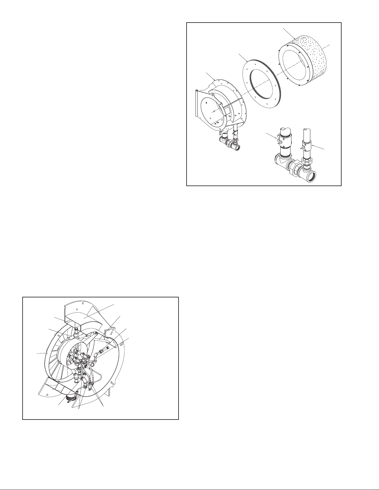
D. FLAME SAFEGUARD CONTROLS
PRIMARY GAS
BUTTERFLY VALVE
SECONDARY GAS
BUTTERFLY VALVE
BURNER HEAD ASSEMBLY
WITH DUAL GAS
MANIFOLD
GASKET
REFRACTORY
DRY OVEN
570-057
1-Dual gas manifold
2-Primary gas orifices
3-Secondary gas spuds
4-Diffuser
5-Scanner tube
6-Gas pilot line
7-Pilot
8-Oil Nozzles
9-Oil lines
10-Air atomizing line
1
2
3
4
5
6
7
8
9
10
021-0583
The ame safeguard programmer incorporates a ame
sensing cell (scanner) to shut down the burner in the event
of pilot ame or main ame failure. Other safety controls
shut down the burner based on sequence of operation as
shown in the manufacturers ame safeguard manual.
E. COMBUSTION AIR HANDLING SYSTEM
The combustion air handling system consists of two major
components:
1. DAMPER ASSEMBLY.
A multi blade system regulates the combustion air volume
and is positioned by a modulating motor. The dampers are
normally ALMOST CLOSED in the low-re position and
opens as the burner drives toward a high-re position.
2. MOTOR DRIVEN IMPELLER.
The diameter of the impeller determines available air pressure and the width determines air capacity in cubic feet per
minute. Alternate motor-impeller combinations are available
for 50 cycle or 60 cycle power and for ring against either
moderate or high furnace pressure. For higher altitudes and
higher furnace pressures, motor and impeller combinations
are determined at the factory.
F. FIRING RATE CONTROLS
Regardless of the fuel used, burner input is fully modulated
between low re and high re on boiler demand. Firing rate
is controlled by the potentiometer-regulated modulating
motor. Combustion air control damper, oil metering valve
and/or gas volume buttery valves are through variable
rate rod and lever linkages. The modulating motor rotates
90 degrees from low to high position.
Flow rate through each component is adjusted by positioning the control rods on the levers and the angular position
of levers on shafts. Lever on the modulating motor shafts
actuate the high re position proving switch.
G. FIRING HEAD
Access to the ring head is provided by swinging open
the impeller housing. First, disconnect the damper linkage,
Figure 1-1
Sec1:4
Figure 1-2
release the housing latch and swing the housing to open
position. An internal gas pilot is standard on all burners.
Pilot gas pressure is adjusted at the pilot pressure regulator.
H. OIL SYSTEM AIR ATOMIZING
S1 Model burners use compressed air for atomization.
Atomizing air is independent of combustion air. The system
is supplied with a separate compressor module for mounting near the burner.
3-WAY SOLENOID VALVE.
Metered oil enters the common port of the 3-way solenoid
valve. During shutdown, pre and post purge the valve is
de-energized (N.C. port closed) and all metered fuel oil
returns to the storage tank. When the valve is energized,
metered oil is directed to the nozzle through the normally
closed port.
NOZZLE ASSEMBLY.
The nozzle assembly consists of four main parts: body,
compression spring, swirler, and tip. The swirler is held
against the nozzle tip by the compression spring. The
nozzle body has inlet ports for air and oil lines. Metered
fuel oil enters the nozzle body and ows through a tube to
the swirler. Oil is forced from the core of the swirler to the
side ports where it meets with the atomizing air. Atomizing
air enters and passes through the nozzle body to grooves
in the swirler, where it mixes with fuel oil. Air/oil passes
through grooves and out of the nozzle orice in a cone of
atomized oil. Proper velocity and angle of the ne spray
ensures good mixing with the combustion air, providing
quiet starts and excellent combustion efciency.
Page 10
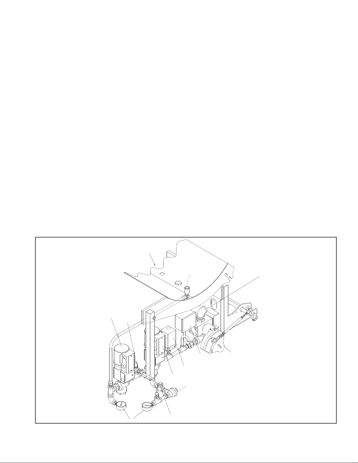
OIL STRAINER
VALVE, 1/2" MOTORIZED 3-WAY OIL
VALVE, MAXON FLOW CONTROL
SWITCH, HIGH OIL PRESSURE
VALVE, 1/2" HORIZONTAL CHECK
SWITCH, LOW OIL PRESSURE
GAUGE, 0-60 PSI
VALVE, 1/2" RELIEF
VALVE, 1/2" MOTORIZED 2-WAY
INLET
FROM SUPPLY
REFERENCE:
GAS MANIFOLD
ASSEMBLY
RETURN
TO SUPPLY
METERED OIL
TO NOZZLE
Prevents foreign matter from entering the burner oil
system.
ATOMIZING AIR PROVING SWITCH
Pressure actuated switch contacts close when sufcient
atomizing air pressure is present.The oil valve will not open
unless switch contacts are closed.
SEPARATE COMPRESSOR MODULE
All burners have a burner mounted oil metering unit and
a separate compressor module. The system functions as
follows:
AIR COMPRESSOR MODULE
Air is supplied by a positive displacement rotary vane
compressor. This provides a constant volume of atomizing air regardless of pressure. The compressor module
includes motor, air/oil reservoir tank, air lter and lube oil
cooling coil. Air enters the compressor through the lter.
The air ows from the compressor into the air-oil separating
and reservoir tank. Filtering material and bafes separate
the lube oil from the compressed air. The tank air pressure forces lubricating oil from the tank to the compressor
to lubricate bearings and vanes. A sight glass indicates
the level of lubricating oil in the air/oil reservoir. Lubricating oil must be visible in the gauge glass at all times. Air
compression heat is absorbed in part by the ow of lube
oil, creating a hot oil mist. The air/oil mist is cooled by a
coil assembly. Lube oil is also cooled before entering the
compressor.
OIL METERING
The oil metering unit is a MAXON Synchro ow control
valve. The multiple screw cam assembly provides mechanical adjustment capabilities to the fuel ratio at each valve
position throughout the entire capacity range.
OPERATION
Fuel is delivered to the metering system at 50 to 70 psi.
Metered oil is delivered to the common port of a 3-way
solenoid valve for transfer to the burner nozzle through the
normally closed port or back to the storage tank through the
normally open port. During pre- and post purge, metered
oil is returned to the tank. During normal ring, all metered
oil is delivered to the nozzle.
Air enters a rotary vane compressor through an air cleaner
where it is compressed to atomizing pressure. Air ows
from the compressor to an air/oil tank which serves the
multiple purpose of dampening air pulsation, lube oil mist
recovery, lube oil and atomizing air storage. Oil vapor is
extracted by a mist eliminator in the upper section of the
tank. Atomizing air from the upper tank section is delivered
to the nozzle at a constant volume. Air pressure increases
as the burner ring rate increases. Atomizing pressure may
be adjusted by the valve located on the compressor air
breather. The valve allows air to be bled from the tank to
the compressor inlet. Delivery rate of the fuel oil metering
is controlled by the modulating motor through adjustable
linkage.
Figure 1-3
Sec1:5
Page 11

I. GAS SYSTEM
Gas is introduced into the combustion zone from a
circular manifold through multiple ports in the blast tube,
and through a pre-mix zone. Firing rate is determined by
the size and number of ports, by manifold pressure and by
combustion zone pressure. The ring rate is regulated by
a rotary, buttery type throttling valve at the manifold inlet.
The valve is actuated by an adjustable linkage from the
modulating motor. Depending upon specic requirements,
one or two safety shutoff, motorized main gas valves are
provided for installation in the gas train upstream of the
buttery valves. Safety shutoff gas valves are wired into
the programming control to automatically open and close
at the proper time in the operating sequence.
MAIN GAS TRAIN COMPONENTS
Depending upon the requirements of the regulating authority, the gas control system and gas train may consist
of some, or all, of the following items. A typical gas train
is shown in Figure 1-4.
GAS VOLUME VALVE.
Two buttery type valves are positioned by linkage from the
modulating motor and controls the rate of ow of gas.
MAIN GAS VALVES.
Electrically operated safety shutoff valve(s) that open to
admit gas to the burner. Standard U.L. burners include: One
motorized gas valve w/closure interlock and one standard
motorized valve.
MAIN GAS REGULATOR
Regulates gas train pressure to specied pressure required at inlet to gas train. Input is set by main gas pressure
regulator adjustment.
MAIN GAS COCKS
For manual shutoff of the gas supply upstream of the
pressure regulator. A second shutoff cock downstream
of the main gas valve(s) provides a means of testing for
leakage through the gas valve(s).
HIGH GAS PRESSURE SWITCH.
A pressure actuated switch that remains closed when
gas pressure is below a pre-selected setting. Should the
pressure rise above the setting, the switch contacts will open
causing main gas valve(s) to close. This switch requires
manual reset after being tripped.
LOW GAS PRESSURE SWITCH.
A pressure actuated switch that remains closed when
gas pressure is above a pre-selected setting. Should the
pressure drop below this setting, the switch contacts will
open, causing main gas valve(s) to close. This switch
requires manual reset after being tripped.
PILOT GAS TRAIN
GAS PILOT VALVE.
A solenoid valve that opens during the ignition period to
admit fuel to the pilot. It closes after main ame is established.
GAS PRESSURE REGULATOR.
Reduces gas pressure to that required by the pilot.
GAS PILOT SHUT-OFF COCK.
For manually closing the pilot gas supply.
Sec1:6
Figure 1-4
Page 12

OPERATION
Metered gas ows through the main gas shutoff cock,
through the pressure regulator to the automatic gas valves
and buttery valve to the gas manifold.
The buttery gas valve modulates ow to burner input
demand. The buttery valves are positioned through
mechanical linkage by the modulating motor. The air control
damper is positioned simultaneously by the modulating
motor.
The automatic gas valve(s) cannot be energized unless
the combustion air proving switch is closed. The low and
high gas pressure switches must be closed to prove proper
gas pressure.
A normally open vent valve, if required, is located between
the two automatic gas valves. This valve is shut when
the automatic gas valves are open. When the automatic
valves are closed, the vent valve is open for venting gas
to the outside, should any be present.
Sec1:7
Page 13

CHAPTER 2
INSTALLATION
A. APPLICATION
Electrical power available is usually 230/460 volt, 3
phase, 60 cycle, or 380 volt, 3 phase, 50 cycle. Control
circuit is 115 volt, single phase, 60 cycle or 115 volt, single
phase, 50 cycle. Refer to the electrical schematic diagram
shipped with the burner. Power connections are made at
the control panel. The burner is furnished with a burner
mounted junction box and remote control panel. Wiring
from the burner junction box to remote panel, panel to boiler
controls, low water controls, remote compressor motor and
remotely located fuel valves is furnished by the installer.
B. INSTALLATION
Locate the burner properly. The burner is designed for
operation with the blast tube level. Do not tilt burner up or
excessively downward. Installation of the refractory oven
or combustion cone, shipped with the burner, is shown in
Figures 2-1 and 2-2. Securely support the burner pedestal
on the oor or foundation. Allow enough clearance at the
rear of the burner to allow the housing to swing open for
service and maintenance. The face of the boiler and burner
ange must be sealed with the gasket provided with the
burner. Carefully place the gasket over the dry oven bolts
before it is mounted onto the burner ange. The I.D. of
the dry oven and burner blast tube are concentric. Due to
bolt hole tolerances, the dry oven may have to be shifted
to accomplish this. After the dry oven nuts are properly
tightened, the burner and dry oven assembly can then be
mounted into the boiler.
C. PACKING PLASTIC REFRACTORY
AROUND OVEN
The area between the outside circumference of the dry
oven and existing refractory should be packed with Kaiser
Refractory Mono T-9 Airset or equal within two hours after
coating the dry oven with Trowleze. From inside the furnace,
ram plastic refractory from the front to the rear parallel to
outside surface of the dry oven.
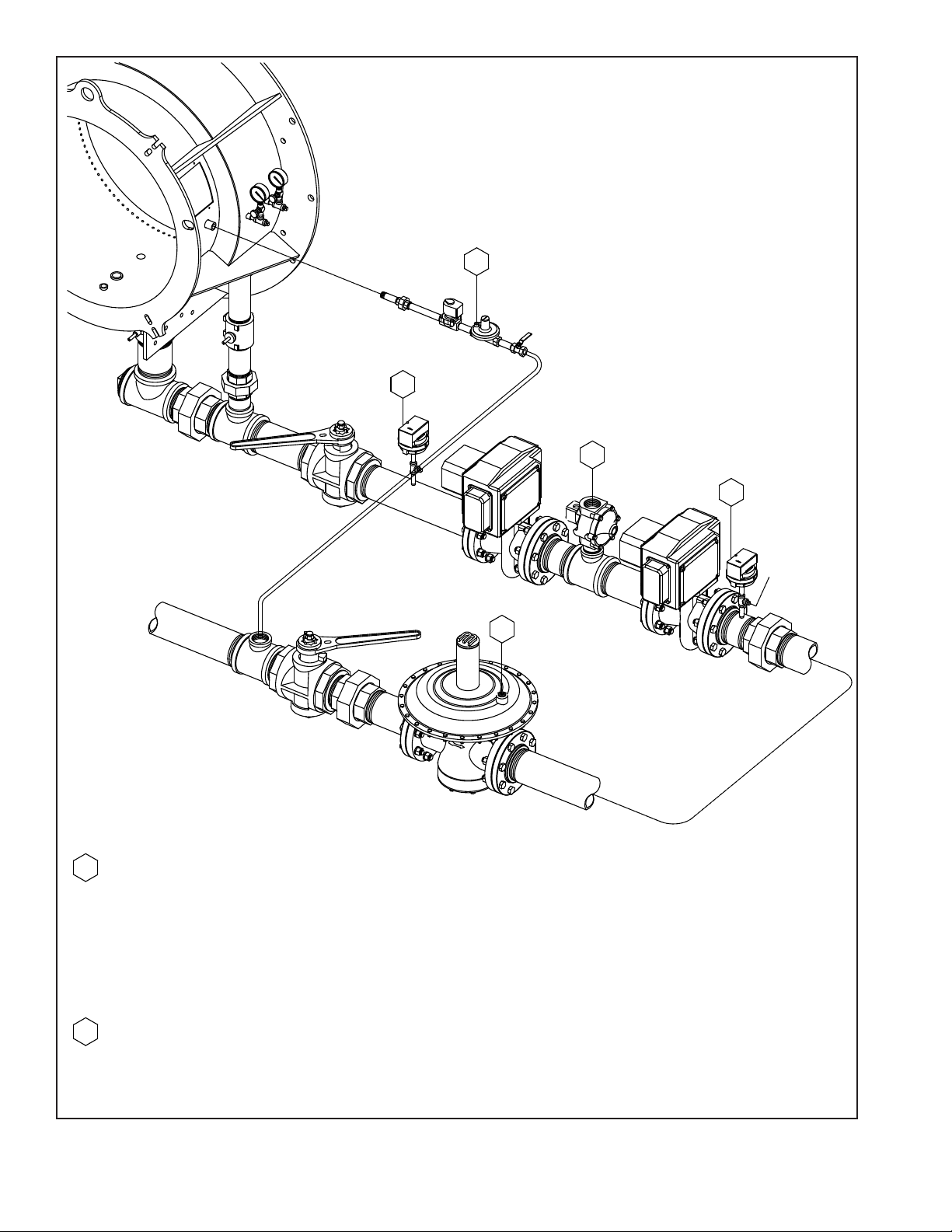
supply entrance and pass through the return line and on to
the tank. Metered oil is pumped (by the metering pump) to
the common port of a 3-way valve. With the 3-way valve
de-energized, the metered oil returns to the tank through
the back pressure valve and return line. When the 3-way
valve is energized, metered oil is passed on to the burner
oil nozzle and atomized by air from the compressor. The
proper strainers, check valves, vacuum and pressure
gauges, etc. should be installed as indicated. All lines
should be pressure tested after installation.
CAUTION
IT IS IMPORTANT THAT YOU PROVIDE
S U P P O R T F O R T H E H O U S I N G
WHEN IN THE OPEN POSITI O N TO
PREVENT DAMAGE TO THE HINGES
AN D SUBSEQUE NT COMPONE NTS.
F. CIRCULATING OIL PUMP
A circulating oil pump is required to deliver fuel oil from
the storage tank to the burner at a minimum of 150% of
the maximum burner ring rate. The excess oil allows a
margin for piping error, viscosity changes in the fuel oil,
and circulating pump wear. Correct pipe sizing is determined by circulating rate , not burner capacity. Install the
pump as close to the supply tanks as possible. Suction lift
should be as low as possible. Maximum suction of 15" Hg
vacuum is good practice for either light or heated heavy
oil. The strainer should be installed in the suction line just
ahead of the circulating pump to prevent foreign material
from entering the pump. Locate the strainer so it may be
easily cleaned.
G. OIL PRESSURE REGULATOR
An oil pressure regulator should be installed in the supply line, close to the burner to regulate oil pressure. Oil
pressure is 50 to 70 PSI to the metering valve.
D. SEPARATE COMPRESSOR MODULE
For oil burners supplied with the separate compressor
module, piping to the burner is installed as shown in Figure
2-4. Copper tubing for the installation is not supplied with
the burner.
E. TYPICAL OIL SUPPLY LOOP
Continuous oil circulation must be supplied to the burner
at a rate of 50 percent greater than the high-re burning
rate. The oil circulating pump should be located as close as
possible to the storage tank to keep suction lines short and
minimize suction loss. Note that the supply line is higher
above the burner metering pump inlet to help eliminate air
problems. The return line to the tank is connected at the
discharge port of the 3-way valve. Note that the return line
should be a minimum of 20 inches higher than the supply
line. Since air rises to the highest point, it will rise from the
Sec1:8
H. GAS PIPING
Refer to Figures, 2-6 for typical gas piping schematics.
Gas service and house piping must supply the quantity
of gas demanded by the unit at the pressure required at
the burner gas train inlet. All piping must be in strict accordance with applicable codes, ordinances and regulations of
the supplying utility. In the absence of other codes, piping
should be in accordance with the following standards:
"National Fuel Gas Code" NFPA No. 54, ANSI No. Z 223.1.
(for Canada: the Canadian Gas Association (CGA) B149
and Canadian Standards Association (CSA) B140 codes
shall prevail)
Gas train components upstream of the buttery valve
are shipped loose. These components should be mounted
by the installer as close to the buttery valve as practical.
Normally, the control train is ordered to suit a particular code
Page 14

1
2
3
BOILER FRONT PLATE
BURNER MOUNTING FLANGE
(2) 1" INSULATING BLANKETS
(KAO-WOOL, CERABLANKET OR DURABLANKET)
2" BLOCK INSULATION
COAT OUTER CIRCUMFERENCE
OF DRY OVEN CONE WITH TROWLEZE
PACK WITH PLASTIC REFRACTORY
KAISER MONO T-9 AIR SET OR EQUAL
(RAM FROM FRONT TO REAR)
1" GASKET SUPPLIED WITH BURNER
STEEL WRAPPER ON CONE
DRY OVEN CONE SUPPLIED WITH BURNER
WRAP DRY OVEN CONE WITH KAO-WOOL
(COAT BOTH SIDES WITH TROWLEZE)
REV DESCRIPTION RELEASE # DRAWN BY REVIEW BY
A
UPDATED TO CURRENT
CAD SOFTWARE
-
GAS
07/30/08
JCS
07/30/08
45°
MIN
FIREBRICK
1
2
3
BOILER FRONT PLATE
BURNER MOUNTING FLANGE
2.5" MINIMUM
TUBE
SHEET
(2) 1" INSULATING BLANKETS
(KAO-WOOL, CERABLANKET OR DURABLANKET)
2" BLOCK INSULATION
COAT OUTER CIRCUMFERENCE
OF DRY OVEN CONE WITH TROWLEZE
PACK WITH PLASTIC REFRACTORY
KAISER MONO T-9 AIR SET OR EQUAL
(RAM FROM FRONT TO REAR)
1" GASKET SUPPLIED WITH BURNER
STEEL WRAPPER ON CONE
DRY OVEN CONE SUPPLIED WITH BURNER
WRAP DRY OVEN CONE WITH KAO-WOOL
(COAT BOTH SIDES WITH TROWLEZE)
45°
MIN
7
REV DESCRIPTION RELEASE # DRAWN BY REVIEW BY
A
UPDATED TO CURRENT
CAD SOFTWARE
-
GAS
07/30/08
JCS
07/30/08
NOTES:
1. LAY THE DRY OVEN ON THE FLOOR WITH THE STUDS UP. CAREFULLY PRESS THE GASKET OVER THE STUDS.
2. LIFT THE DRY OVEN ONTO THE BURNER FLANGE AND GENTLY TIGHTEN THE BOLTS.
3. MAKE SURE THE DRY OVEN IS CENTERED ON THE BURNER FLANGE SO THE SPACE IS EQUAL ALL AROUND THE BURNER BLAST TUBE
4. MAKE SURE THAT NONE OF THE GASKET IS PROTRUDING INTO THE AIR STREAM. TIGHTEN THE DRY OVEN NUTS.
5. WRAP THE DRY OVEN WITH TROWLEZE COATED KAO-WOOL AND LIFT THE BURNER ONTO THE BURNER STUDS AND BOLT SECURELY IN PLACE.
6. FINISH REFRACTORY WORK INSIDE FURNACE.
BURNER MOUNTING DETAILS FOR WATERTUBE BOILERS
Figure 2-1
NOTES:
1. LAY THE DRY OVEN ON THE FLOOR WITH THE STUDS UP. CAREFULLY PRESS THE GASKET OVER THE STUDS.
2. LIFT THE DRY OVEN ONTO THE BURNER FLANGE AND GENTLY TIGHTEN THE BOLTS.
3. MAKE SURE THE DRY OVEN IS CENTERED ON THE BURNER FLANGE SO THE SPACE IS EQUAL ALL AROUND THE BURNER BLAST TUBE
4. MAKE SURE THAT NONE OF THE GASKET IS PROTRUDING INTO THE AIR STREAM. TIGHTEN THE DRY OVEN NUTS.
5. WRAP THE DRY OVEN WITH TROWLEZE COATED KAO-WOOL AND LIFT THE BURNER ONTO THE BURNER STUDS AND BOLT SECURELY IN PLACE.
6. FINISH REFRACTORY WORK INSIDE FURNACE.
BURNER MOUNTING DETAILS FOR SCOTCH MARINE BOILERS
Sec1:9
Figure 2-2
Page 15
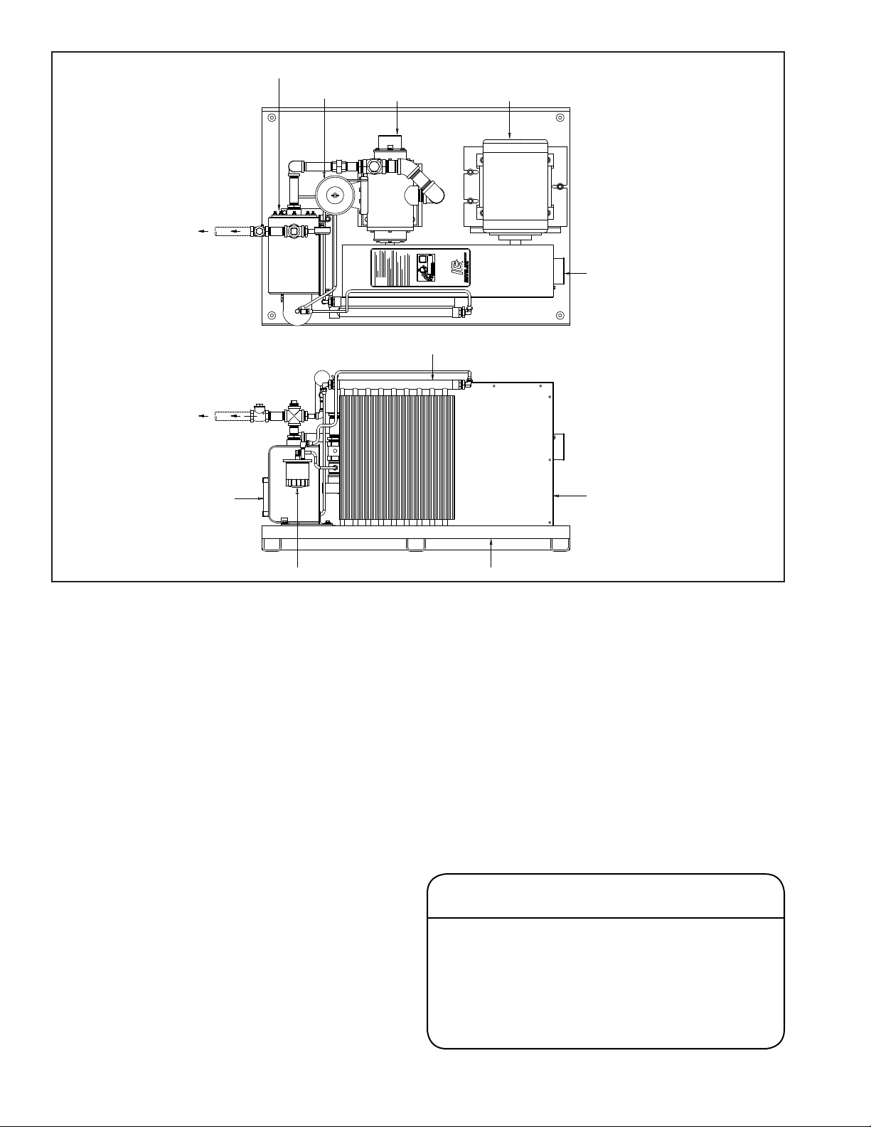
570-071
ATOMIZING
AIR TO
NOZZLE
RADIATOR
R
ELECTRICAL
JUNCTION
BOX
COMPRESSOR BASE
BELT
GUARD
ASSY.
AIR
BREATHER
SIGHT
GLASS
OIL FILTER
MOTORCOMPRESSOR
OIL/AIR
TANK
or insurance regulation - such as Underwriters Laboratories
, Inc., CGA, Factory Mutual, or Industrial Risk Insurance.
Arrange gas piping at the burner so that the burner is
accessible for servicing without disassembly.
The gas pilot supply line must be connected upstream
of the main gas regulator. If a reducing bushing is required
between the house piping and the burner piping, it should
be close to the burner shut-off valve.
The gas piping must be internally clean and free of
foreign material. Before using in service, a leak test must
be performed.
I. INSTALLATION CHECKLIST
All burners are carefully assembled and tested at the
factory, but before being placed in service, all connectors
should again be checked for looseness caused during
shipment.
Check:
1. Electrical terminals in the control panel and on
all electrical components.
2. Pipe ttings and unions.
3. Tubing connections.
4. Nuts, bolts, screws.
Before operating pumps, metering heads and compres-
Figure 2-3
sors, make certain that reservoirs are properly lled with
the specic lubricant. Open all necessary oil shut-off
valves. Do not run compressors, pumps, or metering
units without oil.
Before connecting electrical current to any component,
be sure the supply voltage is the same as that specied
on component nameplates.
Before burner operation, be sure all motors are rotating
in the correct direction. See Motor Rotation Reference on
Sec1:13.
Before ring, make sure that the refractory ame cone
is properly sealed to the burner mounting ange and the
boiler front plate.
Make certain that the operator in charge is properly
instructed in the operation and maintenance procedures.
CAUTION
THE BURNER REFRACTORY CONE IS AIR-CURED
ONLY. HEAT-CURING MUST BE INITIATED AT
INITIAL START-UP. RUN THE BURNER AT LOW
FIRE FOR A PERIOD OF 6 TO 8 HOURS BEFORE
STARTING TO GRADUALY INCREASE THE FIRING
RATE. FAILURE TO DO SO WILL RESULT IN
DAMAGE AND CRACKS IN THE REFRACTORY.
Sec1:10
Page 16
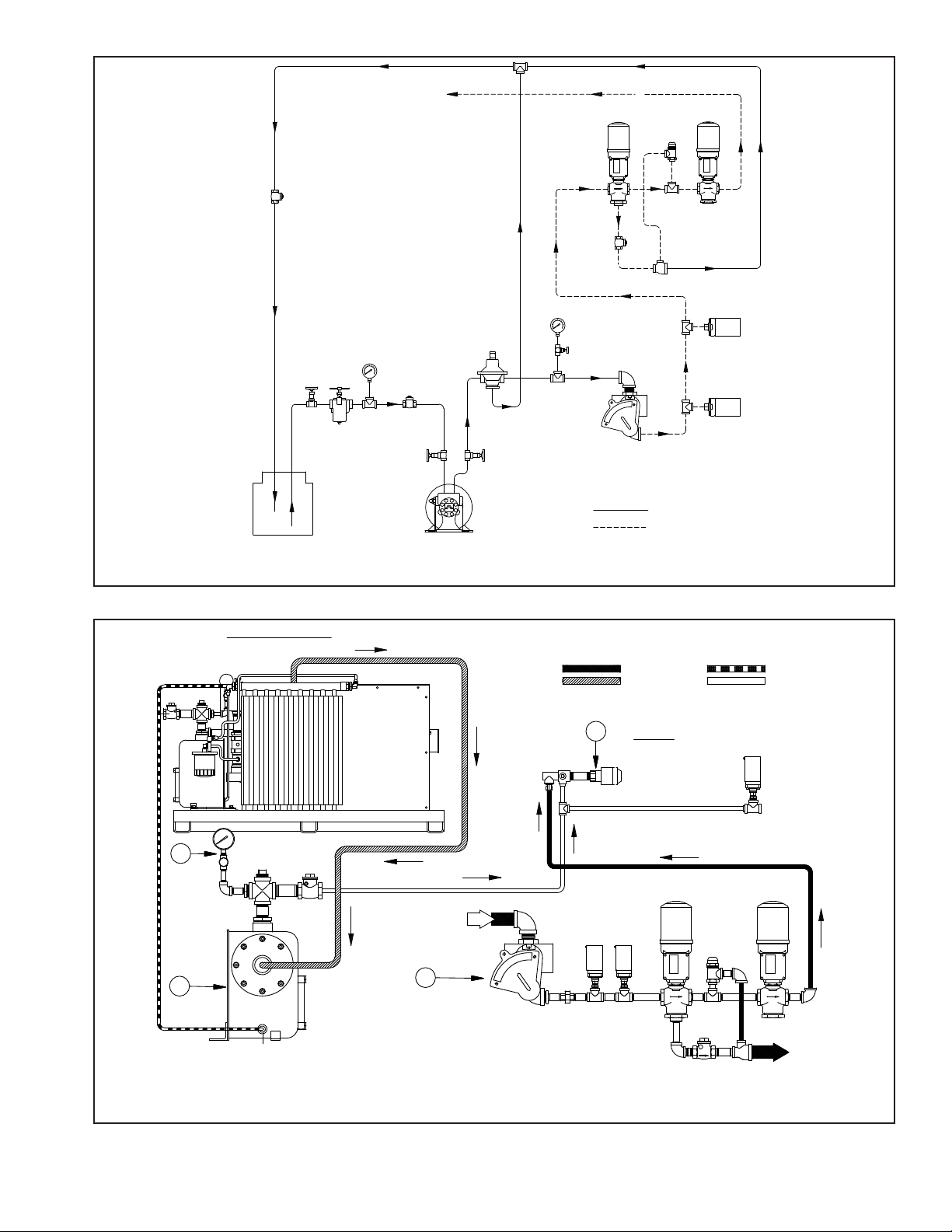
570-070
PRESSURE
REDUCING
STATION
PRESSURE
RELIEF
VALVE
CHECK
VALVE
2-WAY VALVE
(ON BURNER)
H.O.P.S.
L.O.P.S.
NO. 2 OIL PIPING ARRANGEMENT
RETURN
SUCTION
CHECK
VALVE
3-WAY VALVE
(ON BURNER)
OIL METER
(SUPPLIED
WITH BURNER)
PRESSURE
GAUGE &
NEEDLE
VALVE
CHECK
VALVE
VACUUM
GAUGE
STRAINER
GATE
VALVE
GATE
VALVE
GATE
VALVE
PIPING BY OTHERS
PIPING BY CB PROFIRE
OIL
CIRCULATING
PUMP
OIL
STORAGE
TANK
TO DRAWER
ASSEMBLY
570-072
1
3
4
PIPING LEGEND
ATOMIZING
AIR INTERLOCK
SWITCH
BURNER
FROM
STORAGE
TANK
RETURN TO
STORAGE
TANK
2
AIR/LUBE OIL
COMPRESSOR MODULE
1. ATOMIZING AIR PRESS. GAUGE
(SUGGESTED LOCATION)
2. OIL-AIR TANK
3. OIL PIPING
4. BURNER NOZZLE ASSEMBLY
FUEL OIL
ATOMIZING AIR
LUBE OIL
Figure 2-4
Sec1:11
Figure 2-5
Page 17
B
A
1) NORMALLY OPEN VENT VALVE LINE
SHALL BE HALF OF THE MAIN GAS
TRAIN PIPING SIZE. (3/4" MIN.)
1) FULL SIZE (1/4" OR LARGER) PIPE TO
BE RUN FROM THE VENT OPENING TO
OUTSIDE OF BUILDING.
2) NO TRAPS ALLOWED IN VENT LINE.
3) VENT LINE SHALL TERMINATE AWAY FROM
ALL DOORS AND WINDOWS.
4) PROVISIONS SHALL BE MADE TO PREVENT
FOREIGN OBJECTS FROM ENTERING
VENT PIPING.
A
REGULATOR
SHUTOFF
COCK
HIGH GAS
PRESSURE
SWITCH
A
Maxon
Maxon
570-0076
B
PILOT
VALVE
PILOT
SHUTOFF
COCK
TEST
OPENING
TYPICAL
REGULATOR
N.O.
VENT
VALVE
MAIN GAS
VALVE
W/P.O.C.
MAIN GAS
VALVE
SHUTOFF
COCK
LOW GAS
PRESSURE
SWITCH
A
A
BURNER MOUNTING DETAILS FOR SCOTCH MARINE BOILERS
Sec1:12
Figure 2-6
Page 18
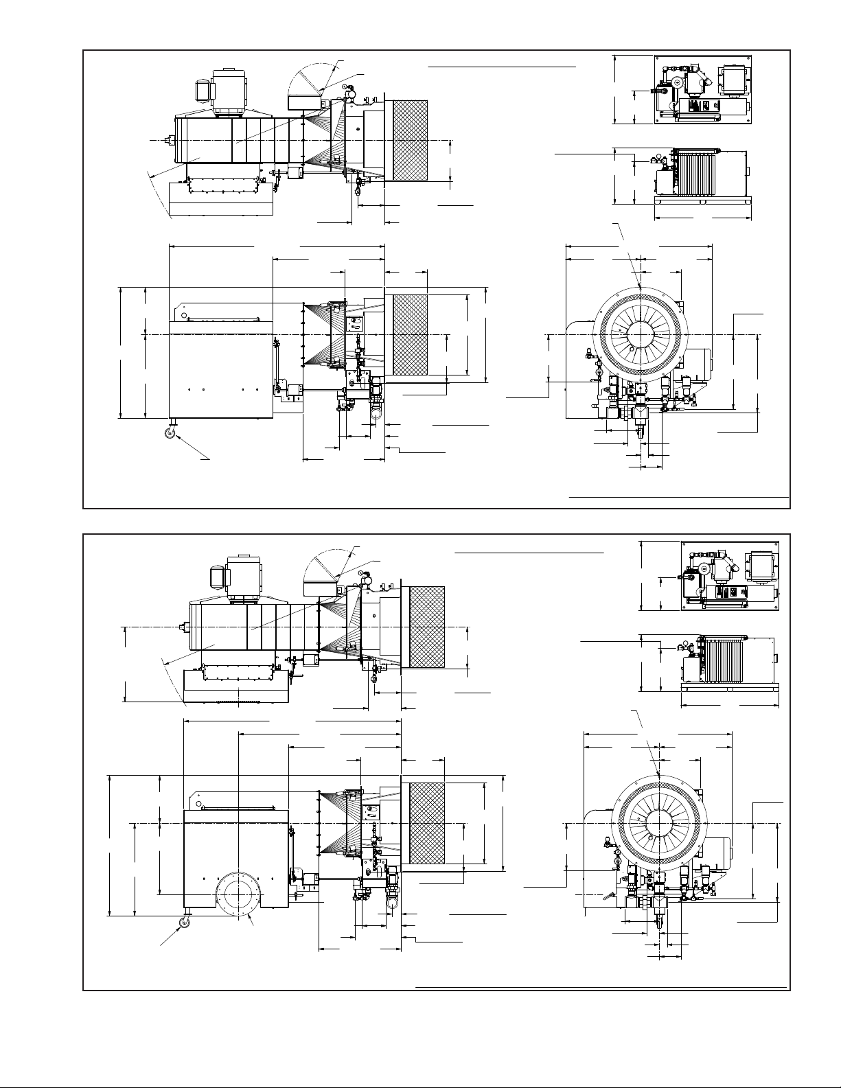
S1-SERIES DIMENSION DIAGRAM
R
GENERAL DIMENSIONS
570-096
16-1/8
28
GAS TRAIN CONNECTION
FROM EITHER SIDE
16-3/4
OIL
INLET
55-3/8
23-1/2
103-3/4 R
72-1/2
41-1/4
64-3/4
106-1/2
21-1/8
34
OIL
INLET
16-1/4
(12) HOLES 3/4" DIA.
EQUALLY SPACED AS SHOWN
ON A 45" DIA. B.C.
NOTE:
THESE DIMENSIONS ARE FOR REFERENCE
ONLY. SPECIFICATIONS AND DIMENSIONS
ARE SUBJECT TO CHANGE WITHOUT NOTICE.
AIR OUTLET
1" NPT
48
GAS PILOT
INLET
6-1/4
10-5/8
3-7/8
OIL
RETURN
MAIN GAS
INLET
38-5/8
36-7/8
13-1/4
20-1/4
OIL INLET
1" NPT
23-7/8
21
11-3/4
35-1/237
OIL RETURN
1-1/4" NPT
23-1/8
40-5/8
22-1/2
7-3/8
4 3/8
ELECTRICAL
JUNCTION BOX
39-5/8
ADJUSTABLE BURNER SUPPORT
(5" WHEEL ASSEMBLY)
L
HINGE C
19-3/4
HINGE C
20
L
MAIN GAS
INLET 4" NPT
GAS PILOT
INLET
1/2" NPT
47
16-3/8 R
R
LNS1-SERIES DIMENSION DIAGRAM (BOTTOM ACCESS)
GENERAL DIMENSIONS
69
35
45-1/2
16-1/8
28
21-1/8
34
AIR OUTLET
1" NPT
48
570-097
16-3/8 R
47
GAS PILOT
INLET
1/2" NPT
MAIN GAS
INLET 4" NPT
L
20
HINGE C
19-3/4
HINGE C
L
ADJUSTABLE
BURNER SUPPORT
(5" WHEEL ASSEMBLY)
39-5/8
ELECTRICAL
JUNCTION BOX
4 3/8
7-3/8
22-1/2
40-5/8
23-1/8
OIL RETURN
1-1/4" NPT
37 35-1/2
11-3/4
21
23-7/8
OIL INLET
1" NPT
20-1/4
13-1/4
36-7/8
38-5/8
MAIN GAS
INLET
OIL
RETURN
3-7/8
10-5/8
6-1/4
GAS PILOT
INLET
NOTE:
THESE DIMENSIONS ARE FOR REFERENCE
ONLY. SPECIFICATIONS AND DIMENSIONS
ARE SUBJECT TO CHANGE WITHOUT NOTICE.
(12) HOLES 3/4" DIA.
EQUALLY SPACED AS SHOWN
ON A 45" DIA. B.C.
16-1/4
106-1/2
72-1/2
103-3/4 R
23-1/2
55-3/8
79-3/4
OIL
INLET
36-1/2
F.G.R. INLET
CONNECTION
F.G.R. INLET
13-1/4" ID. x 21" OD.
(12) TAPPED HOLES 1/2-13 UNC.
EQUALLY SPACED AS SHOWN ON
A 18-3/4" DIA. B.C.
GAS TRAIN CONNECTION
FROM EITHER SIDE
OIL
INLET
16-3/4
Figure 2-7
Sec1:13
Figure 2-8
Page 19
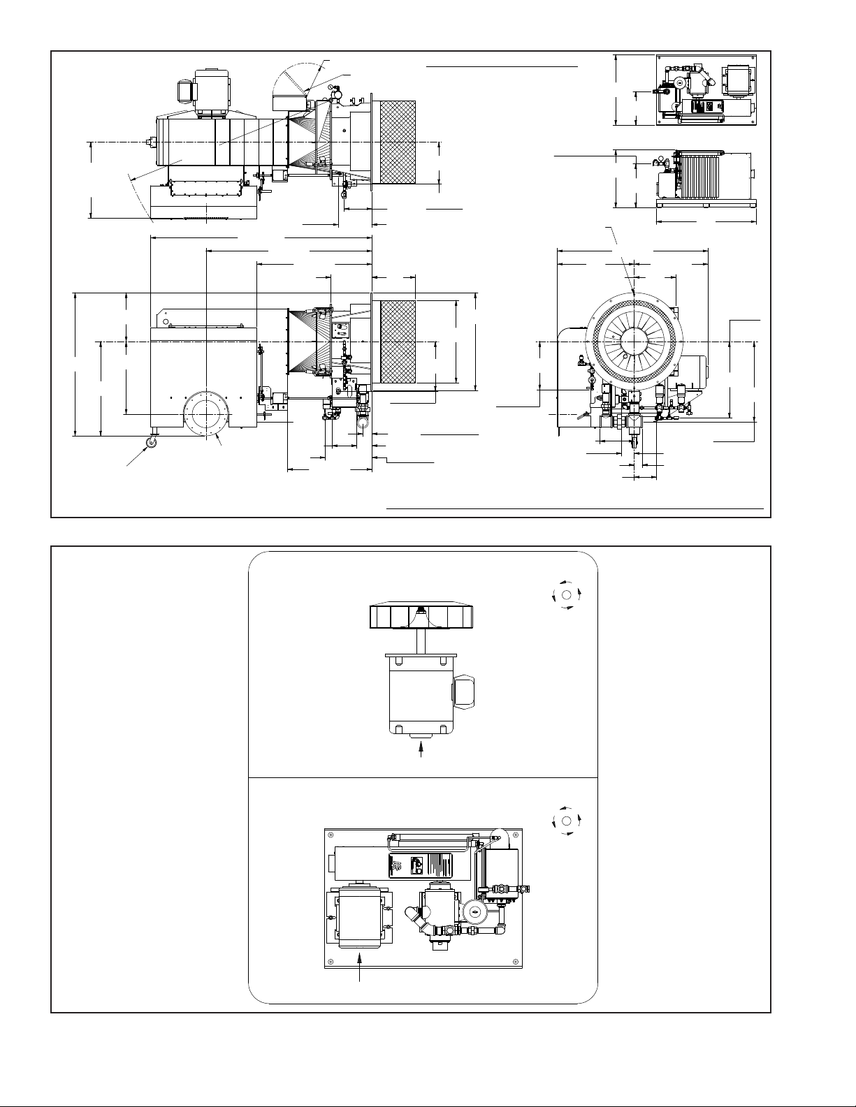
Figure 2-9
R
LNS1-SERIES DIMENSION DIAGRAM (BOTTOM ACCESS)
GENERAL DIMENSIONS
69
35
45-1/2
16-1/8
28
21-1/8
34
AIR OUTLET
1" NPT
48
570-097
16-3/8 R
47
GAS PILOT
INLET
1/2" NPT
MAIN GAS
INLET 4" NPT
L
20
HINGE C
19-3/4
HINGE C
L
ADJUSTABLE
BURNER SUPPORT
(5" WHEEL ASSEMBLY)
39-5/8
ELECTRICAL
JUNCTION BOX
4 3/8
7-3/8
22-1/2
40-5/8
23-1/8
OIL RETURN
1-1/4" NPT
37 35-1/2
11-3/4
21
23-7/8
OIL INLET
1" NPT
20-1/4
13-1/4
36-7/8
38-5/8
MAIN GAS
INLET
OIL
RETURN
3-7/8
10-5/8
6-1/4
GAS PILOT
INLET
NOTE:
THESE DIMENSIONS ARE FOR REFERENCE
ONLY. SPECIFICATIONS AND DIMENSIONS
ARE SUBJECT TO CHANGE WITHOUT NOTICE.
(12) HOLES 3/4" DIA.
EQUALLY SPACED AS SHOWN
ON A 45" DIA. B.C.
16-1/4
106-1/2
72-1/2
103-3/4 R
23-1/2
55-3/8
79-3/4
OIL
INLET
36-1/2
F.G.R. INLET
CONNECTION
F.G.R. INLET
13-1/4" ID. x 21" OD.
(12) TAPPED HOLES 1/2-13 UNC.
EQUALLY SPACED AS SHOWN ON
A 18-3/4" DIA. B.C.
GAS TRAIN CONNECTION
FROM EITHER SIDE
OIL
INLET
16-3/4
BURNER AIR
IMPELLER
AIR
COMPRESSOR
MOTOR ROTATION, COUNTER CLOCKWISE REFERENCE
570-0075
ROTATION IS DETERMINED BY FACING THE REAR OF THE MOTOR
MOTOR ROTATION, COUNTER CLOCKWISE REFERENCE
ROTATION IS DETERMINED BY FACING THE REAR OF THE MOTOR
REAR
R
REAR
Sec1:14
Figure 2-10
Page 20

CAUTION
CAUTION
BEFORE OPENING THE GAS SHUT-OFF
VALVES, READ THE REGULATOR INSTRUCTIONS CAREFULLY. OPEN SHUTOFF VALVE SLOWLY TO ALLOW INLET
PRESSURE TO BUILD-UP SLOWLY IN THE
REGULATOR UNTIL IT IS FULLY PRESSURIZED. OPENING THE SHUT-OFF VALVE
QUICKLY WILL DAMAGE THE REGULATOR.
DO NOT EXCEED THE REGULATOR PRESSURE RATINGS.
LUBRICATING OIL IS DRAINED FROM THE
AIR OIL TANK BEFORE SHIPMENT.
BEFORE ATTEMPTING TO START THE
BURNER, ADD OIL TO THE RECOMMENDED LEVEL .
Sec1:15
Page 21

CHAPTER 3
OPERATION
A. PREPARATIONS FOR STARTING
When the installation is complete and all electrical, fuel,
water and vent stack connections are made, make certain
said connections are tight. The operator should become
familiar with the burner, boiler controls and components.
To identify controls and components, refer to contents
of Chapter 1. Adjustment procedures given in Chapter
4 should be reviewed prior to ring. The wiring diagram
should also be studied along with the operating sequence
of burner programmer.
Read and understand starting instructions before attempting to operate the burner. Before attempting to start
the burner, the following checks must be made:
1. BOILER.
Check the boiler water level. Be sure all boiler valves
are installed correctly and positioned properly. Set the
high limit control sightly above the desired temperature.
Set modulating controls at the desired temperature or
pressure.
2. BURNER.
Check the electrical power supply to the burner in accordance with the nameplate voltage on all motors and
the control circuit. Check the direction or rotation of the
motors. Open the housing to check the electrode setting.
Refer to Chapter 5, Figure 5-2, Sec1:30. Check the gas
pilot pressure at the pilot gas regulator. Normal setting is
18" to 20" W.C.
For protection in shipment, the ame safeguard control
chassis is shipped unmounted. Check all screw connec-
tions before attaching ame safeguard chassis to base.
Screw must be secure to assure low resistance connections. The relay chassis is mounted on the sub-base with
a screw which, when tightened, completes the connection
between the sub-base and chassis contacts. Press manual
reset button to be sure safety switch contacts are closed.
Check control linkage for proper movement of the air
volume damper and fuel metering components. This can
be done by loosening the linkage at the actuator level and
manipulating by hand.
Check the air shutter and adjust low-re setting.
3. FIRING PREPARATIONS FOR OIL BURNERS.
Prior to initial ring, oil ow pressure and temperature
should be veried.
Inspect the compressor lube oil sump level. Add oil to
bring the oil level to the midpoint or slightly higher in the
reservoir sight glass. Fill with non-detergent SAE30 oil.
Make certain that the drive belts or couplings are aligned
and properly adjusted.
To verify air ow and pressure, momentarily ip the switch
“ON” and immediately turn “OFF”. The programmer will
continue through its cycle, however, without ignition or energizing the fuel valves. Observe the air pressure gauge.
With compressor running and no oil ow, the pressure
should be approximately 10 psi.
If the burner is a dual fuel model, make certain that the
main gas shut off cock is closed and the fuel selector switch
set to “OIL”.
OIL FLOW.
Open all valves in the oil suction and return line. The
burner oil metering units are not capable of creating suction.
Fuel oil must be supplied to the metering unit at a nominal
50 to 70 psi pressure by a circulating supply pump.
A vacuum (or compound pressure-vacuum) gauge should
be installed in the oil suction line, and its reading noted.
This gauge indicates the tightness of the suction system.
4. OIL- AIR TANK (LUBE OIL).
Check the lube oil level in the air-oil tank. Inspect oil level
regularly. Loss of oil will damage the compressor. Fill the
tank with non detergent SAE30 oil to a level midway up
the sight glass. Do not overll the tank.
For normal environment use SAE30 oil. For a 32 degree
F. and below environment use SAE10 oil. Change oil every
2000 hours of operation.
5. FIRING PREPARATIONS FOR GAS BURNERS.
A representative of the gas utility should turn on the gas.
Determine by a test gauge upstream of the burner regulator
that sufcient pressure exists at the entrance to the gas
train. The gas pressure regulator must be adjusted to the
pressure required and the pressure setting recorded.
On combination fuel models, set the selector switch to
gas. On initial start-up, it is recommended that the main
gas shutoff cock remain closed until the programmer has
cycled through pre-purge and pilot sequences to determine
that the main gas valve opens. Turn the burner switch "OFF"
and let programmer nish its cycle. Check to see that gas
valve closes tightly. Set the high and low gas pressure
switches.
Check for leaks and determine there is adequate gas
pressure available at the burner for operating at full capacity.
Check with the local utility if necessary. Check gas pressure at the pilot and the main burner. Close the manual
gas valve.
B. ELECTRICAL INTERFERENCE TEST
Prior to putting the burner into service, conduct the following test to ascertain that the ignition spark will not cause
the ame relay to pull in.
1. GAS FIRED.
Close the pilot and the main line manual gas valves.
Start the burner and at time of pilot trail with just the
electrical ignition system energized, the ame relay
should not pull in (i.e. be energized).
Upon completion of successful test, proceed with
start-up proceedures.
Sec1:16
Page 22

2. OIL FIRED
Disconnect the electrical power to the burner.
Disconnect the electric oil safety shutoff valve.
Reconnect electric power to the burner. Close the pilot
line manual gas valve, if used.
Start burner and at the time of pilot trial, with just the
electrical ignition system energized, the ame relay
should not pull in.
Upon completion of successful test, disconnect power
supply. Reconnect oil safety shutoff valve and turn on
manual pilot gas valve. Reconnect power supply and
proceed with start-up procedures.
C. GAS PILOT FLAME ADJUSTMENT
The gas pilot ame is regulated by adjusting the pressure setting of the pilot regulator. Normal setting is 18"
to 20" WC when the pilot is burning. The ame must be
sufcient to be proven by the ame detector and ignite the
main ame.
Although it is possible to visibly adjust the size of the
pilot ame, obtain a proper DC volt or microamp reading
of the ame signal.
The ame safeguard amplier has a meter jack for this
purpose. At initial start-up and during planned maintenance,
test the pilot ame signal, pilot turndown, and safety switch
lockout.
D. START-UP SEQUENCE
The programming control sequences the operation of all
controls and components through the starting, ignition, ring, and shutdown cycle. The burner and control system
are in starting condition when:
a. The operating and high limit control (temperature or
pressure) are below their cutoff setting;
b. All power supply switches are closed;
c. Power is present at the control panel.
Refer to the manufacturers literature on programming
controls and burner wiring diagrams for detailed information.
Begin starting sequence, with burner switch off, and 1.
with all manual valves closed. Switch main power
on. (Power On) light.
When ring oil, open the manual oil valves.2.
When ring on gas, open the main manual gas valve.3.
When ring on gas, manually reset the high and low 4.
gas pressure switches.
Place the gas / oil selector switch in position for 5.
desired fuel. With all limit and operating
controls calling for heat, the burner will follow the
Flame Safeguard Sequence below.
When the burner motor starts, open the gas cock.6.
If ring on gas, when the main fuel lamp lights 7.
indicating pilot ame proven open the the manual
leak test valve.
Time in Seconds External Operation
0 Provided the fuel valve is proven closed
the burner motor and ame safeguard
timer will start.
7 Air ow must be proven before ignition,
or the ame safeguard will lockout. If
the interlock circuit opens during a ring
period, the burner will shut off and the
ame safeguard will lockout.
60 Firing on gas and providing the air ow
and low-re have been proven, the pilot
ignition transformer and ignition lamp are
energized and the gas pilot valve opens
to ignite the pilot.
70 Firing on oil, providing air ow and pilot
have been proven, the main fuel lamp
lights. When on gas or oil, the main
valve opens to ignite the burner at low
re.
80 The pilot ignition transformer is de-ener-
gized, and the main safety shut-off pilot
valve closes, scanner proves main ame
only. If the low/auto swtich is in the auto
position, the following will occur:
On gas, the buttery valve and the burner air louvre moves to "low-re" position.
On oil, the metering pump and the burner
air louvre moves to "low-re" position.
100 "Normal run" position. Burner continues.
E. AUTOMATIC SHUTDOWN
Limit or operating controls open:
100 Fuel valves close. Main fuel lamp goes
off. Flame safeguard timer starts.
115 Flame safeguard timer and burner motor
stop. Burner is ready for start-up on the
next call for heat.
F. MANUAL SHUTDOWN
1. Turn gas/oil selector switch off. Burner shuts down in
Automatic Shutdown as above.
2. When burner motor stops, close all manual valves.
G. SAFETY SHUTDOWN
1. If at any time during the operating cycle a ame failure
occurs, the burner shuts down as in Automatic Shutdown,
with an additional post-purge, and the ame failure lamp
is energized.
A. The lockout switch on the ame safeguard control
must be manually reset before the burner will re
again.
2. If a low water condition occurs, the burner shuts down
as in Automatic Shutdown.
3. If a high or low gas pressure condition occurs while
ring on gas, the burner shuts down as in Automatic
Shutdown.
A. Condition must be corrected and the respective gas
pressure switch manually reset before the burner
will re again on gas.
Sec1:17
Page 23

H. START-UP AND OPERATING
GAS BURNERS
Close the main and pilot gas cocks. Make sure the
“ON-OFF” switch is in the “OFF” position and the fuel selector switch on “GAS”. Actuate the manual reset button
of the ame safeguard control to close the safety switch
contacts.
Set the “MANUAL-AUTO” switch in the “MANUAL” position.
Set the manual potentiometer in low re position.
Open the gas pilot cock.
Set the “ON-OFF” switch to “ON”. The burner will start
and pre-purge. After pre-purge, the ignition transformer and
the gas pilot solenoid are energized. Before proceeding,
conduct electrical interference and pilot turndown tests if
not previously done. Refer to Paragraph B.
On initial start-up it is recommended that the main gas
shutoff cock remain closed until the programmer has cycled
through prepurge and pilot sequence. Then determine that
main gas valve opens. When this is conrmed, turn the
burner switch “OFF” and let programmer nish its cycle.
Check to see that gas valve has closed tightly. If ignition
does not occur, turn the burner switch “OFF” and allow
programmer to recycle for a new ignition trial.
start-up of a combination burner, it is recommended that
oil ring be adjusted before gas ring. Gas low ring rate
is set to match oil low re rate.
Be sure the “ON-OFF” switch is in the “OFF” position and
the fuel selector switch is on “OIL”. Actuate the manual
reset button of the ame safeguard control to close the
safety switch contacts. Be sure the “MANUAL-AUTO”
switch is in “MANUAL” position. Set manual modulating
control potentiometer in “LO” re position.Open the pilot
gas valve (if used).
Set the “ON-OFF” switch to “ON”. The burner will start
and pre-purge. After pre-purge, the ignition transformer
and the gas pilot are energized. Before proceeding, conduct electrical interference and pilot turndown tests if not
previously done. Refer to Chapter 4, Sections C and D.
Observe the primary atomizing air pressure gauge on the
air/oil tank. The gauge reading should be approximately
10 psi during pre-purge.
When the pilot ame is proven, the programmer will proceed to the main ame position. Allow the burner to operate
in low re, to warm the boiler before moving to high-re.
Turn burner “ON” and after pilot ignition when the ame
relay pulls in, the slow opening, motorized, main gas valve
is energized. Slowly open the downstream manual shutoff
gas cock. Main ame should ignite at this time. The gas
valve and air damper continue advancing until high re is
reached.
Do not repeat unsuccessful light off attempts without
rechecking burner and pilot adjustment. Vent fuel vapors
from the combustion chamber after each unsuccessful
light off attempt. Set the gas low re rate by adjusting
buttery valve and air linkage. When low re is adjusted,
shut down burner. Restart several times to be sure the
low re setting is suitable. Readjust if necessary. Never
start the burner with fuel vapor in the furnace. In case of
emergency, open main power switches and close all fuel
valves. After combustion adjustments are satisfactorily set,
allow the heating vessel to slowly reach normal operating
pressure or temperature.
Turn the potentiometer switch to the high re position.
Check high re at this point using combustion instru-
ments.
Do not disturb established low re adjustment. Allow the
burner to return to low re position before adjusting high
or intermediate settings.
High re combustion analysis typically is 9 to 10.5 percent
CO2. When conditions covered above are assured, refer
to Sections I and J.
OIL BURNERS
The fuel selector switch should be set to “OIL”. On initial
Typically, for No. 2 through 4 oil, CO2 is 8 to 11 percent
at low re.
Turn the manual potentiometer switch to the high re
position. Check high re combustion at this point. Do not
disturb previously established low re adjustment. Allow
the burner to return to low re position before adjusting
high or intermediate settings. The primary atomizing air
pressure will increase automatically with the oil ow rate.
Typically, for No. 2 oil, CO2 is 10 to 13 percent at high
re.
When conditions covered above are assured, refer to
sections I and J
I. NORMAL OPERATION
Normal operation must be with the “MANUAL-AUTO”
switch selector at “AUTO”.
In automatic operation, the operating cycle always proceeds sequentially through pre-purge, pilot ignition, main
ame ignition, run and post-purge. The length of purge
and ignition trial vary according to the type of programmer
used.
During the run cycle, burner input is regulated to the load
demand by the modulating pressure or temperature control
on the boiler. The burner will continue to modulate until
the operating pressure or temperature is reached.
Programmer control operation should be tested when
the burner is initially placed into service, when a control is
replaced, and at scheduled intervals in the maintenance
program.
Refer to adjustment procedures and maintenance instructions given in Chapters 4 and 5.
Sec1:18
Page 24

J. SHUTDOWN
When the operating limit control setting is reached or
the burner switch is turned “OFF”, the following sequence
occurs:
The fuel valve(s) de-energize and ame extinguishes.
The blower motor continues running during post-purge.
At the end of the post-purge, the blower motor is de-energized. The programmer returns to its starting position
and stops. Unit is ready to restart.
Abnormal shutdown might result from motor overload,
ame outage, low water, current or fuel supply interruption,
combustion or atomizing air pressure below minimum level,
tripped circuit breakers, blown fuses, or other interlock
devices. Check for cause and correct before restarting
burner.
Safety shutdown caused by ignition or ame failure will
actuate a red indicator light and energize an audible alarm
(if so equipped). If the programmer has a non-recycling
interlock circuit, any interruption in this circuit during the
pre-purge or ring cycle will cause a safety shutdown. This
type of shutdown requires manual reset of the programming control and must be corrected before operation can
be resumed.
WARNING
AN ULTRAVIOLET FLAME SENSOR ELECTRICAL SPARK
INTERFERENCE TEST MUST BE PERFORMED AFTER
FINAL ADJUSTMENT. SEE THIS SECTION PARAGRAPH
"B" FOR ADDITIONAL INFORMATION.
Sec1:19
Page 25

CHAPTER 4
ADJUSTMENTS
A. GENERAL
While each burner is tested at the factory for correct
operation before shipment, variable conditions such as
burning characteristics of the fuel used and operating load
conditions may require further adjustment after installation
to assure maximum operating efciency.
Prior to placing the boiler into initial service, a complete
inspection should be made of all controls, connecting
piping, wiring and all fastenings such as nuts, bolts and
setscrews to be sure that no damage or misadjustments
occurred during shipping and installation.
A combustion efciency analysis made during the initial
start-up will help to determine what additional adjustments
are required in a particular installation.
B. COMBUSTION ADJUSTMENT ON GAS
AND OIL
Efcient combustion cannot be properly judged by ame
appearance, although it may help in making preliminary
settings.
The proper settings of air-fuel ratios must be determined
by ue gas analysis. Combustion gas analysis indicates
the air to fuel ratio and the degree of complete combustion.
Instruments are available to measure carbon dioxide (CO2),
oxygen (O2), and carbon monoxide (CO).
STACK TEMPERATURE
Net stack temperature is obtained by subtracting the
ambient temperature from the ue gas temperature. A
high net stack temperature indicates wasted heat. Stack
temperature should be as low as possible without causing
ue gas condensation.
Stack heat loss can be reduced by decreasing either the
temperature or the volume of the ue gas, or both. Flue
gas temperature is reduced by improving heat transfer or
by reducing excess combustion air. A certain amount of
excess air is necessary to complete combustion. More
efcient burners require minimum excess air.
SMOKE MEASUREMENT
Smoke measurements can be made using a variety
of different methods. The standards will vary somewhat
according to the equipment used, and instructions accompanying the instrument should be followed.
Smoky combustion can result from: Improper air delivery,
insufcient draft, improper fuel viscosity, improper fuel-air
ratio, excessive air leaks in the combustion chamber, or
improper fuel oil temperature.
GAS ADJUSTMENTS
Low re combustion analysis typically is 7 to 9 percent
CO2 and less than .04 percent CO (400 ppm). High re
reading typically is 9 to 10.5 percent CO2 and less than
.04 percent CO.
FUEL OIL ADJUSTMENTS
Adjust for a “clean re”. Typically for No. 2 oil, CO2 is 8
to 11 percent at low re and 10 to 13 percent at high re,
with a maximum of #1 spot (ATSM D2156 Shell-Bacharach
scale).
C. ELECTRICAL INTERFERENCE TEST
Prior to putting the burner into service, conduct the following test to ascertain that ignition spark will not cause
the ame relay to pull in.
GAS FIRED
Close the pilot and main line manual gas valves.
Start the burner and at time of pilot trial with just the
electrical ignition system energized, the ame relay should
not pull in (i.e. be energized).
Upon completion of successful test, proceed with start-up
procedures.
OIL FIRED
Disconnect the electrical power to the burner.
Disconnect the electric oil safety shutoff valve.
Reconnect electric power. Close the pilot line manual
gas valve, if used.
Start burner and at the time of pilot trial, with just the
electrical ignition system energized, the ame relay should
not pull in.
Upon completion of successful test, disconnect power
supply. Reconnect oil safety shutoff valve and turn on
manual pilot gas valve. Reconnect power supply and
proceed with start-up procedures.
D. GAS SYSTEM
GAS PRESSURE
Gas must be supplied at a pressure high enough to
overcome the pressure loss in the burner gas train and
furnace pressure while running at full input. Refer to nameplate inside control panel for gas pressure requirements
at train inlet and manifold. The pressures listed are based
on nominal 1000 Btu/cu ft natural gas at elevations up to
2000 feet above sea level.
GAS FLOW
The volume of gas is measured in cubic feet as determined
by a meter reading. The gas ow rate required depends
on the heating value (Btu/cu ft). The supplying utility can
provide this information as well as pressure correction
factors. To determine the required number of cubic feet
per hour of gas, divide burner input (Btu/hr) by the heating
value (Btu/cu ft).
NOTE
WHEN CHECKING THE INPUT RATE, MAKE SURE
NO OTHER EQUIPMENT IS OPERATING ON THE
SAME METER.
Sec1:20
Page 26

The ame safeguard amplier has a meter jack for this
SHUT/OPEN
SCALE & VALVE
STEM
SHUT/OPEN
SCALE & VALVE
STEM
1
/
2
PRIMARY
GAS VALVE
1
/
2
SHUT
OPEN
1
/
2
OPEN
S
H
U
T
OPEN
SECONDARY
GAS VALVE
DEC.
INC.
INC.
DEC.
INC.
DEC.
SHAFT
ROTATION
VALVE STEM
ROTATION
VALVE STEM
ROTATION
570-074
purpose. At initial start-up and during planned maintenance,
test the pilot ame signal, pilot turndown, and safety switch
lockout.
MAIN GAS PRESSURE REGULATOR
The gas pressure required at the burner manifold is the pres-
sure that is required to re the burner at its rated capacity.
The gas pressure regulator must be adjusted to achieve
this pressure to assure full input. Refer to manufacturer’s
literature for regulator adjustment.
WARNING
AN ULTRA-VIOLET FLAME SENSOR ELECTRICAL SPARK INTERFERENCE TEST MUST BE
PERFORMED AFTER FINAL ADJUSTMENT.
SEE SECTION C OF THIS CHAPTER FOR
ADDITIONAL INFORMATION.
LOW GAS PRESSURE SWITCH
Turn adjusting screw until indicator moves to a pressure
setting slightly below the operating gas pressure. The
control will break a circuit if pressure is below this set point.
The control should be nally adjusted to prevent operation
with low gas pressure, but not at a pressure so close to
normal operating pressure that unnecessary shutdowns
occur. The switch must be manually reset after tripping.
To reset, allow gas pressure to rise and press the manual
reset button.
reading.
With the high re air-fuel ratio established, the gas pressure regulator needs no further adjusting.
Recheck low re and adjust if necessary.
Proper setting of the air/fuel ratios at all rates must be
determined by combustion analysis.
GAS VALVES ADJUSTMENT
The secondary valve feeds gas to the inner spuds. A slot
in the valve stem in relationship to the shut/open scale on
the valve indicates the blade position. Both low and high-
re positions are approximate. Adjustments to the valve
should be made on the secondary valve linkage arm. To
increase the travel, move the linkage arm closer to the pivot
point. To decrease the travel, move the linkage arm away
from the pivot point. The primary valve which feeds the
outer spuds should be adjusted as normal. See Diagrams
4-5 at the end of this section for adjustments.
HIGH GAS PRESSURE SWITCH
Turn adjusting screw until indicator moves to a pressure
setting slightly above the maximum operating gas pressure.
The control will break a circuit if pressure exceeds this value.
The control should be adjusted to prevent operation with
excessive gas pressure, but not at a pressure so close to
normal operating pressure that unnecessary shutdowns
occur.This switch must be manually reset after tripping.
To reset, allow gas pressure to drop and press the manual
reset button.
GAS COMBUSTION ADJUSTMENT
After operating for a sufcient period of time to assure a
warm boiler, make adjustments for most efcient combustion.The buttery gas valve directly controls the rate of
ow. The low re light-off setting should be regarded as
preliminary until proper gas pressure for high re operation
is established.
Determine the actual gas ow from a meter reading at
high re. With the buttery valve open and with regulated
gas pressure set, the actual ow rate should be quite close
to the required input. If corrections are necessary, increase
or decrease the gas pressure by adjusting the gas pressure
regulator, following manufacturer’s directions for regulator
adjustment.
When proper gas ow is obtained, take a ue gas analysis
Figure 4-1
CAM TRIM ADJUSTMENT
Fine tuning the modulating cam.
After low and high re adjustments are complete, nal
adjustment is made with the cam assembly to obtain a
good air/fuel ratio throughout the entire ring range. The
input of combustion air is xed at any given point in the
modulating cycle. The fuel input may be varied to obtain
correct ue gas readings. The adjustment is made to the
metering cam by means of the 14 adjusting screws which
are turned in (clockwise from the hex-socket end) to in-
crease the ow of fuel, and out (counterclockwise from
the hex-socket end) to decrease it. A 3/32" hex key is
required. It will be necessary to cut off the short end of the
hex key to approximately 3/8" to adjust the rst two socket
head setscrews at the low re position. Take a combustion
analysis at various points of the cam prole. Adjustment
can be made without cycling the burner then operate the
Sec1:21
Page 27

Figure 4-2
570-068
SETPOINT
LOCKING
SETSCREWS
ROTATION
90° FULL
SWING
FUEL
INPUT
INCREASE
FUEL
INPUT
DECREASE
CAM TRIM SETPOINTS
(TURNING SETSCREW CLOCKWISE
WILL INCREASE FUEL INPUT)
LOW FIRE START POSITION
OF ROLLER GUIDE MUST FALL
WITHIN THESE LIMITS
RETURN SPRING
TENSION SETTING
TENSION
INCREASE
LINKAGE ARM FOR F.G.R. VALVE
OR GAS BUTTERFLY VALVE
TENSION
DECREASE
DRIVE
LINKAGE ROD
ASSEMBLY
ROLLER
GUIDE
SETTING
FUEL
INPUT
DECREASE
FUEL
INPUT
DECREASE
FUEL
INPUT
INCREASE
FUEL
INPUT
INCREASE
ROLLER GUIDE
DRIVEN
LINKAGE ARM
SETTING
FUEL
INPUT
DECREASE
FUEL
INPUT
INCREASE
automatic modulating cycle to assure satisfactory results.
Tighten the locking set screws.
E. OIL SYSTEM
OIL METERING SYSTEM.
Fuel oil supply to the integral metering unit must be 50
to 70 psi. The oil spray should ignite as soon as the oil
solenoid valve opens. If a burner failure occurs, check the
following:
1. See that the oil tanks are not empty.
2. That all oil valves between the burner and the tank are
open.
3. That the suction line is not airbound.
4. That the low-re setting has not been disturbed.
5. That there is pressure at the integral metering unit, but
not to exceed 80 psi.
6. That the circulating pump turns freely.
7. Check for a clogged strainer at the suction side of the
circulating pump.
8. Check for a dirty burner strainer.
9. Check for a plugged or carboned nozzle. This will
show up as excessive primary air pressure.
10.That the oil by-pass valve is not by-passing the
metered fuel oil.
To adjust the metering valve, proceed as follows:
1. Check that the air dampers are closed.
2. During pre-purge, check that the valve travels its full
quadrant range from minimum to maximum.
3. The oil ow is adjusted by screwing "in" the locking allen
screws located on the side of the valve. With SYNCHRO
valve at minimum position, screw down (clockwise) to permit
fuel ow to the burner. Once your ame is established and
rened at this position, screw all remaining screws down at
Sec1:22
least the same level as your rst adjusting screw.
4. A preliminary setting can be established with all the remaining screws. Generally each succeeding screw needs
to be screwed in approximately one full turn deeper than
its preceding screw. A smooth "stair-step" gradient preset at this point from low to high will simplify the remaining
adjustment steps.
5. Adjust each screw to match the air supply and obtain a
clean re. Take combustion analysis as referred in section B.
6. Advance valve to the #2 screw position and adjust.
7. Progressively work your way up through each adjusting
screw position, developing a smooth progression slope from
your rst screw to the maximum position. Take combustion
readings at each point. To adjust the ame at any position,
you must move the ow control valve to the number you
desire to adjust. This aligns the adjusting screw directly
on top of the fuel valve plunger. A resulting adjustment of
the screw is directly applied to the fuel valve plunger and
its interconnected valve body linkage.
8. Rene adjustments as needed, always turning valve so
that position indicator matches screw being adjusted. To
avoid possible damage to cam strips, always turn all higher
numbered screws in as far as the last one adjusted. For
more fuel, turn screw in (clockwise). For less fuel, turn
screw out (counter-clockwise). If screw must be turned
in ush with carrier casting, increase fuel pressure and
re-adjust.
9. Cycle burner from minimum to maximum and rene
adjustments if necessary. Always set ow control valve to
the numbered position you wish to adjust.
See Diagram 4-6 for adjustments.
ATOMIZING AIR PRESSURE.
Atomizing air in the air/oil tank is regulated by adjusting
Page 28

valve in the return air line on integral metering units or in
the air inlet on air compressor module burners. The air
pressure is indicated by the pressure gauge at the air/oil
tank. A minimum of 10 psi air pressure in low re is suggested. As the ring rate increases, the air pressure also
increases. Air pressure will be less with light oils. If any
change in atomizing air pressure is made, check ignition
several times for reliable light off. Adjustments should be
set to obtain reliable ignition with best low and high re
combustion results. If the required atomizing air pressure
cannot be maintained, a lack of lubricating oil may be the
cause or the intake lter may be dirty.
Figure 4-3
ATOMIZING AIR PROVING SWITCH.
The knurled nut between the switch and bellows is turned
in to raise pressure setting. The minimum amount of atomizing air is during pre- and post-purge. During pre-purge,
adjust switch until it breaks the circuit. Readjust switch
above this circuit break point to actuate under a condition
of minimum pressure, but not so close as to cause nuisance
shutdowns. Since the pressure of the atomizing air is at
minimum when no fuel is present at the nozzle, adjustment
of the switch should be made while the unit is purging, but
not ring.
indicates the air to fuel ratio and the degree of complete
combustion. The closer the rod comes to parallel with
the lever, the slower the rod moves. The angles of the
driven levers on the jackshaft can be adjusted to vary
the rate of good air/fuel ratio throughout the entire ring
range. The input of combustion air is xed at any given
point in the modulating cycle. The fuel input may be
varied to obtain correct ue gas readings. The adjustment is made to the metering cam by means of the 14
adjusting screws which are turned in (clockwise from
the hex-socket end) to increase the ow of fuel, and out
(counterclockwise from the hex-socket end) to decrease
it. A 3/32" hex key is required. It will be necessary to
cut off the short end of the hex key to approximately
3/8" to adjust the rst two socket head setscrews at the
low re position. Take a combustion analysis at various points of the cam prole. Adjustment can be made
without cycling the burner; then operate the automatic
modulating cycle to assure satisfactory results. Tighten
the locking set screws.
G. FIRING RATE CONTROLS
Firing rate adjustments are made at the modulating
motor linkages to the combustion air inlet damper, oil
metering valve and main gas buttery valve. Settings
are determined by the operating length of the levers
and the angular position on the shafts. Increasing the
lever lengths on damper, pump or valve decreases the
ow rate. Driving and driven levers are approximately
parallel, but the angles can be adjusted to vary the rate of
change. The most rapid rod travel occurs when the lever
is perpendicular to the rod. The closer the rod comes to
being parallel with the lever, the slower the rod moves.
ALWAYS allow the burner to return to low re position
before adjusting high or intermediate settings. DO NOT
alter low re settings. Normally, the air control damper
will be almost closed in low re position. For best pilot
operation, the damper should be set as low as possible.
Excessive opening in low re can cause pilot ignition
problems. Air to the pilot is supplied under pressure to
compensate for variations in furnace pressure, but the
damper must be in low re position for reliable ignition.
(See Figure 4-4, 4-7, 4-8)
F. LINKAGE-MODULATING MOTOR
The linkage consists of adjustable cams, levers, rods and
ball joints that transmit motion from the modulating motor to
the air damper, gas buttery valve, and oil metering unit.
When properly adjusted, coordinated movement of the
air and fuel control devices provide proper fuel/air ratios
through the ring range. In linkage adjustments, several
important factors serve as guides:
1. The modulating motor must be able to complete its
full travel range. Restrictions will damage the motor
and /or the linkage.
2. Lever and rod adjustments should be made with
the motor in the low re position.
The modulating motor will be stopped at the end of its
stroke by an internal limit switch. Combustion gas analysis
Sec1:23
Page 29

HIGH FIRE
INTERLOCK
SWITCH
PRIMARY AIR
PRESSURE
SWITCH
AIR DAMPER BLADE
ROD & LINKAGES
ADJUSTMENT
DECREASE
TO GAS/OIL
LINKAGES
REVERSING
ACTUATOR
INCREASE
INCREASE
DECREASE
570-093
Figure 4-4
Sec1:24
Page 30

INITIAL FUEL
VALVE BLADE
POSITIONING
FUEL INPUT
DECREASE
PRIMARY GAS LINKAGE
(SHOWN AT LOW-FIRE POSITION)
FUEL INPUT
INCREASE
FUEL INPUT
INCREASE
FUEL INPUT
DECREASE
FUEL INPUT
DECREASE
SECONDARY GAS LINKAGE
(SHOWN AT LOW-FIRE POSITION)
FUEL INPUT
INCREASE
FUEL INPUT
INCREASE
FUEL INPUT
DECREASE
INITIAL FUEL
VALVE BLADE
POSITIONING
570-088
Sec1:25
Figure 4-5
Page 31

(TOP VIEW)
INITIAL OIL
FLOW CONTROL
VALVE POSITIONING
OIL FLOW CONTROL VALVE
(SHOWN AT LOW-FIRE POSITION)
FUEL INPUT
DECREASE
REF.
FUEL INPUT
INCREASE
INCREASE
AIR DAMPER DRIVE LINKAGE
(SHOWN AT LOW-FIRE POSITION)
DECREASE
INCREASE
REF.
DECREASE
570-089
Sec1:26
Figure 4-6
Page 32

F.G.R. BLADE LINKAGE (BOTTOM ACCESS)
(SHOWN AT LOW-FIRE POSITION)
DECREASE
INCREASE
INC.
DEC.
CAM FOLLOWER WHEEL
REF.
POSITIONED UNDER 1ST
ADJUSTMENT SCREW
BOTTOM HOLE
F.G.R. BLADE LINKAGE (TOP ACCESS)
(SHOWN AT LOW-FIRE POSITION)
INC.
(MAXIMUM SPRING TENSION)
DECREASE
INCREASE
REF.
Sec1:27
DEC.
CAM FOLLOWER WHEEL
POSITIONED UNDER 1ST
ADJUSTMENT SCREW
BOTTOM HOLE
(MAXIMUM SPRING TENSION)
570-090
Figure 4-7
Page 33

AIR DAMPER BLADE LINKAGES
(SHOWN AT LOW-FIRE POSITION)
END
HOLE
END
HOLE
4th
HOLE
23°
35°
53°
69°
6 5/16
REF
6 3/4
REF
DRIVE
ARM
6 3/8
REF
37°
35°
5th
HOLE
53°
6th
HOLE
3rd
HOLE
LEFT SIDE
LINKAGE
Sec1:28
RIGHT SIDE
LINKAGE
570-090
Figure 4-8
Page 34

CHAPTER 5
MAINTENANCE
WARNING
ANY COVER PLATES, ENCLOSURES, OR
GUARDS ANCHORED TO THE BURNER, OR
ANY BURNER RELATED EQUIPMENT, MUST
REMAIN IN POSITION AT ALL TIMES. ONLY
DURING MAINTENANCE AND SERVICE
SHUTDOWN CAN THESE COVER PLATES,
ENCLOSURES, OR GUARDS BE REMOVED.
THEY MUST BE REPLACED, AND SECURELY
ANCHORED BEFORE TESTING, ADJUSTING,
OR RUNNING THE BURNER OR BURNER
RELATED EQUIPMENT.
CAUTION
IT IS IMPORTANT THAT YOU PROVIDE SUPPORT
FOR THE HOUSING WHEN IN THE OPEN POSITION TO PREVENT DAMAGE TO THE HINGES
AND SUBSEQUENT COMPONENTS.
A. GENERAL
A maintenance program avoids unnecessary down time,
costly repairs, and promotes safety. It is recommended
that a record be maintained of daily, weekly, monthly, and
yearly maintenance activities.
Electrical and mechanical devices require systematic
and periodic inspection and maintenance. Any “automatic”
features do not relieve the operator from responsibility, but
rather free him from certain repetitive chores, providing
time for upkeep and maintenance.
Unusual noise, improper gauge reading, leak, sign of
overheating, etc., can indicate a developing malfunction,
requiring corrective action.
tions demand. A periodic safety check procedure should be
established to test the complete safeguard system. Tests
should verify safety shutdown with a safety lock out upon
failure to ignite the pilot or the main ame, and upon loss
of ame. Each of these conditions should be checked
on a scheduled basis. The safety check procedures are
contained in the manufacturer’s bulletin.
D. FIRING HEAD INSPECTION
Disconnect the damper linkage, release the impeller
housing latch and swing the housing open for access to the
ring head. Inspect the ame scanner lends to be sure it
is clean and the support tube is in proper position to sight
the ame through the hole in the diffuser. Inspect the lead
wire to the ignition electrode. It must be rmly attached
and the insulation should be clean and free of cracks. The
oil nozzle should be inspected periodically depending on
the grade of oil burned and the cleanliness of the environment.
E. PILOT AND IGNITION ELECTRODE
The ignition transformer requires little attention other
than making sure the ignition wire is rmly attached to the
transformer and the electrode. Be sure the wire insulation
is in good condition and not grounded. Failure to keep the
ignition electrode clean and properly set can cause faulty
operation. Refer to Figure 5-1, for electrode gap setting
and position. The pilot assembly is supported by a socket
in the diffuser and gas inlet tube. No adjustment is required
except proper positioning of the electrode wire.
IGNITION PILOT ELECTRODE SETTING
GAP - 3/32"
B. CONTROL SYSTEM
Most operating controls require very little maintenance
beyond regular inspection. Examine electrical connections. Keep the controls clean. Remove any dust from the
interior of the control. Covers should be left on controls
at all times. Keep the control cabinet doors closed. Dust
and dirt can damage motor starters and relay contacts.
Starter contacts are plated with silver and are not harmed
by discoloration. Never use les or abrasive materials
such as sandpaper on contact points.
C. PROGRAMMING CONTROL
This control requires no adjustment, nor should any attempt be made to alter contact settings or timing logic. Those
programmers with contacts may require occasional cleaning. If so, follow instructions given in the manufacturer’s
bulletin. Never use abrasive materials. The manufacturer’s
bulletin also contains troubleshooting information. The
ame detector lens should be cleaned as often as condi-
Sec1:29
570-013
Figure 5-1
F. FLAME SCANNER
The scanner must be clean. Even a small amount of
contamination will reduce the ame signal. Wipe the scanner lens with a clean soft cloth.
Page 35

GAS PILOT
LINE
FUEL
OIL
ATOMIZING
AIR
NOZZLE BODY
570-077
DIFFUSER
NOZZLE, TIP & SWIRLER
ELECTRODE
PILOT
GAS
SPUDS
S1 STANDARD DRAWER ASSEMBLY
MANIFOLD
TUBE
SLEEVE
O-RING
NOZZLE BODY
FUEL
OIL
ATOMIZING
AIR
GAS PILOT
LINE
CABLE
GUIDE
CABLE
ELECTRODE
PILOT
GAS
SPUD
LNS1 DRAWER ASSEMBLY
BLAST TUBE
ASSEMBLY
NOZZLE TIP
SWIRLER &
SPRING
DIFFUSER
570-094
Figure 5-2
Sec1:30
Page 36

570-0078
PRIMARY
GAS PORTS
GAS PILOT
ASSEMBLY
OIL TO
NOZZLE
SECONDARY
GAS SPUD
SCANNER TUBE
WITH EXTERNAL
SCANNER
ATOMIZING AIR
TO NOZZLE
REFRACTORY
OVEN
BURNER
MOUNTING
GASKET
(CUT) SIDE VIEW OF INTERNALS
FIRING HEAD ASSEMBLY
7/8" FROM NOZZLE TIP TO
DIFFUSER FRONT (CONE)
2" FROM DIFFUSER FACE
TO BURNER MTG. FLANGE
DO NOT ATTEMPT TO USE WIRE OR A SHARP
METAL TOOL TO CLEAN THE NOZZLE ORIFICE
AS THIS WILL DISTORT THE FINE ORIFICE AND
RUIN THE NOZZLE. USE A SHARP POINTED
PIECE OF SOFT WOOD.
IT IS ESSENTIAL THAT THE CAM SPRING,
CAM FOLLOWER BEARING WHEEL AND CAM
FOLLOWER ARM AT THE PIVOT POINT BE
GREASED SPARINGLY EVERY MONTH TO
ENSURE SMOOTH OPERATION OF THE CAM
ASSEMBLY. REGULAR AUTOMOTIVE BEARING GREASE SHOULD BE USED.
G. OIL NOZZLE
Successful burner operation requires use of the proper style
nozzle tip and keeping the orice clean. Standard nozzle
tips furnished on the burners are of a special emulsifying
type which delivers a spray of extreme neness and at
an angle which insures proper mixing with the air stream.
Unsatisfactory performance and loss of efciency can result from the use of nonstandard nozzle tips. If the burner
ame becomes stringy or lazy, it is possible that the nozzle
spring is not properly in place or the nozzle is clogged. This
problem is usually indicated by an abnormally high reading
on the atomizing air pressure gauge on the air-oil tank. To
CAUTION
NOTE
Figure 5-3
remove the nozzle, disconnect the oil and air tubes to the
nozzle assembly. Refer to Figure 2. To clean the nozzle
tip and swirler, unscrew the tip from the nozzle body. Use
care not to distort the tube. Hold the nozzle body in a vise
or use two wrenches, one on the body and one on the
tip. Disassemble the nozzle tip. Carefully clean all parts
in solvent and reassemble the nozzle. To insure proper
atomizing, the tip must be screwed in tightly with the swirler
seating spring pressing the swirler tight against the nozzle
tip. Turn the swirler a few times to be sure it ts snugly in
the nozzle and the spring is pressing the two parts rmly
together. When reinstalling, be sure the nozzle is centered
with the proper distance from the diffuser.
H. DIFFUSER
The diffuser is factory set and does not require attention
under normal operating conditions. If fouled with carbon,
the diffuser should be removed for cleaning. First remove
the electrode and scanner leads, the gas pilot assembly,
air and oil tubes and the nozzle support assembly, before
you attempt to remove the diffuser. Mark the diffuser relative position to the blast tube, with a scribed or pencil line
where the three mounting screws are located, to insure that
the diffuser is placed back in the same position. Remove
the three screws holding the diffuser to the blast tube and
slowly pull the diffuser along the blast tube towards the
ring head. Keep the diffuser as parallel as possible. If it
should became stuck or tight, do not apply any tool which
would distort the shape or blade conguration. A small
wooden block tapped gently against the diffuser's outer
edge will help expedite its removal. Clean all carbon from
the diffuser vanes and reinstall in reverse order,
Sec1:31
Page 37

aligning the diffuser with the scribed marks. Do not attempt to drive the diffuser back along the blast tube with
anything other than a small block of wood tapped against
the diffuser's outer edge. When reinstalling, be sure the
diffuser is centered.
I. FIRING RATE CONTROLS
Check all rods and linkages. Make sure all connections
are tight. Adjust if necessary. Perform a combustion test
as per Chapter 4 Adjustments, and readjust burner if necessary.
J. BURNER MOUNTING INSPECTION
The seal between the burner ange and furnace front
plate must not permit combustion gases to escape. Periodic inspection is important. If leakage occurs, refer to
Chapter 2, Section D for proper sealing procedure.
K. FUEL OIL SYSTEM
FUEL OIL CIRCULATING PUMP.
Failure of the circulating pump to deliver sufcient oil may
be due to one of the following reasons:
1. Insufcient fuel oil in the storage tank.
2. Suction line or check valve clogged.
3. Air leaks or air traps in the suction line. If the line has
a high point at which an air trap can occur, the line
must be changed.
4. Oil strainer clogged (line strainer or burner strainer).
5. Suction line piping too small.
6. Pump rotating in wrong direction
7. Three phase pump motor operating on single phase
because of fuse failure.
8. Low voltage applied to pump motor.
PRIMARY AIR COMPRESSOR
The air compressor itself requires little maintenance,
however its life is dependent upon sufcient clean, cool
lubricating oil. The oil level in the air-oil tank must be
checked regularly. Lack of oil will damage the compressor.
Disassembly or eld repairs to the air compressor are not
recommended. Check the air-oil tank sight glass for proper
oil level. The level should be kept at midpoint up the glass.
The compressor rotor must turn freely. All tube connections
must be air tight.
Alignment of the compressor and motor sheaves and
proper belt tension are important.
Belt tension is adjusted according to the displacement
on the belt with thumb pressure. The displacement should
be 3/8 to 1/2 inch.
To adjust, loosen the two bolts on the compressor mounting
ange and the three setscrews which hold the compressor
in place.
The mounting ange is slotted at the top, which permits
belt tightening. If the slot in the mounting ange is insufcient for obtaining proper belt tension, the modular base
has two extra holes for this purpose.
Move the top bolt to the next hole and adjust. Tighten
bolts and setscrews. Replace belt guards. If belt becomes
frayed or cracked, replace it.
CAUTION
DO NOT ATTEMPT FIELD REPAIR OF THE
COMPRESSOR. INSTALLATION OF A NEW
COMPRESSOR IS MANDATORY. SEND THE OLD
COMPRESSOR IN FOR REPAIR OR EXCHANGE
(WHERE ALLOWED).
AIR CLEANER
Never operate the compressor without the air cleaner in
place. The cleaner should be cleaned at regular intervals.
The correct oil level must be maintained in the air cleaner.
Use the same oil used for air compressor lubrication.
OIL-AIR TANK
Check the lube oil level in the oil -air tank. Inspect oil
level regularly as loss of oil will damage the compressor.
Change oil every 2000 hours of operation. The oil-air tank
should be drained once a year and thoroughly ushed.
Remove the mist eliminator pads from the upper section of
the tank, wash thoroughly in kerosene and dry. Rell with
non detergent SAE30 oil to a level midway up the sight
glass. For normal environment use SAE30 oil. For a 32
degree F. and below environment use SAE10 oil.
OIL LEVEL SIGHT GAUGE
The oil level sight gauge can be cleaned by removing it
from the air-oil tank and soaking it in a detergent solution.
If cleaning the gauge proves unsatisfactory, replace it.
COMPRESSOR OIL FILTER (Lube Oil Strainer)
The lube oil strainer prevents foreign materials from
entering the compressor. The strainer screen must be
cleaned at regular intervals.
The screen is easily removed for cleaning by unscrewing
the bottom plug. Immerse in solvent and thoroughly
clean.
OIL STRAINERS
Oil strainers should be cleaned frequently to maintain
a free and full ow of fuel. The strainer screen must be
removed and cleaned at regular intervals. The screen
should be removed and cleaned thoroughly by immersing
it in solvent and blowing it dry with compressed air. Light
oil strainers should be cleaned each month. Heavy oil
strainers should be checked and cleaned as often as the
experience indicates the necessity.
L. GAS SYSTEM
MOTORIZED MAIN GAS VALVES.
Should the valve fail to operate, check for voltage at the
valve. Make certain that the main shutoff cock is closed
prior to testing. The actuator is not eld repairable nor
should it be disassembled. Replace the actuator if the
valve fails to operate. After replacement, cycle the valve
with the fuel shutoff to determine that it opens and closes.
If the valve has a visual indicator, observe its position for
correct operation.
Sec1:32
Page 38

SOLENOID VALVES.
A slight hum from the solenoid is normal when the coil
is energized. Should the valve fail to operate, check that
there is voltage at the valve coil. If there is no voltage at
coil, check for loose wiring connections. If there is proper
voltage at the valve coil and the valve still fails to open,
replace the coil. Refer to manufacturer’s bulletin for correct
procedure in coil replacement.
Should it become necessary to replace the complete
valve, be sure that the ow is in the drection of the arrow
on the body.
Test for gas leaks and check valve action several times
to ensure proper operation before attempting to relight
burner.
CAUTION
ALL POWER MUST BE DISCONNECTED
BEFORE SERVICING THE VALVES.
M. ELECTRICAL SYSTEM
Because of the many types of ame safeguard systems
applicable to this equipment, complete descriptions of all
D/Series burner electrical systems are beyond the scope
of this manual. An individual electrical schematic drawing
is shipped with each burner and complete operation and
troubleshooting instructions are available from the various
ame safeguard system manufacturers.
ELECTRIC MOTORS.
Motor supply voltage must not vary more than 10 percent
from nameplate ratings. At initial start-up and at least once
a year thereafter, check the motor current with a meter while
the burner is in high re position. If the reading exceeds
the nameplate rating plus service factor, determine the
cause and correct it immediately. In dusty locations, clean
the motor regularly to assure adequate cooling. Lubricate
in accordance with the manufacturer’s instructions.
N. EXTENDED SHUTDOWN
When shutting down the burner for an extended period of
time, the operator should use the following general guidelines to protect the burner from its surrounding elements.
This will add to the operating life of the burner.
1. Turn the main electrical disconnect switch to the
burner to OFF.
2. Close all main fuel valves.
3. If the burner operates in a damp environment, cover
it with plastic to protect all electrical components
from moisture. Remove the ame safeguard control
and store in a dry atmosphere.
O. COMMON VENT LINE
1) FULL SIZE (1/4" OR LARGER) PIPE TO BE RUN FROM THE VENT OPENING TO OUTSIDE OF BUILDING.
A
2) NO TRAPS ALLOWED IN VENT LINE.
3) VENT LINE SHALL TERMINATE AWAY FROM ALL DOORS AND WINDOWS.
4) PROVISIONS SHALL BE MADE TO PREVENT FOREIGN OBJECTS FROM ENTERING VENT PIPING.
1) NORMALLY OPEN VENT VALVE SHALL BE HALF OF THE MAIN GAS TRAIN PIPING SIZE (3/4" MIN.).
B
TYPICAL GAS TRAIN
561-098
Figure 5-4
Sec1:33
Page 39

P. MAINTENANCE FLOW CHART RECOMMENDED TEST SCHEDULE
ITEM SERVICE BY REMARKS
DAILY
Gauges, Monitors,
and Indiactors
Instrument and
Equipment Settings
Low water, Fuel cutoff and Alarms
Firing rate control Operator Verify factory settings
Igniter Operator Make visual inspection. Check ame signal strength.
Pilot and Main Fuel
Valves
Flame Failure
Controls
Flame Signal Strength
Controls
Linkages Operator Check all burner linkages for tightness. Tighten if
Operator Make visual inspection and record readings in log.
Operator Make visual check against recommended
specications.
Operator Refer to instructions.
WEEKLY
Operator Open limit switch. Make audible and visual check.
Check valve position indicators, and check fuel
meters.
Operator Close manual fuel supply for (1) pilot and (2) main fuel
cock and/or valve(s). Check safety shutdown timing.
Record in log.
Operator Read and log the ame signal for both pilot and main
ame. Notify Service if readings are very high, very
low, or uctuating.
required.
MONTHLY
Low Fan Pressure
Interlock
High and Low Gas
Pressure Interlocks
Scanner and Diffuser Operator Check, inspect and clean for soot buildup.
Pilot Assembly Operator Check for loosening of components, erosion or carbon
Strainer (Oil units) Operator Replace or clean the oil strainer element.
Impeller Operator Inspect and clean the combustion impeller.
Combustion Test Service
Pilot Turndown Test Service
Operating Controls Service
Operator Manually adjust until switch opens
Operator Refer to instructions. Manually adjust until switch
opens.
buildup.
ANNUALLY
Perform a complete combustion test. Adjust burner if
Technician
Technician
Technician
necessary. Read and log data.
Required after any adjustment to ame, scanner, or
pilot adjustment.
Refer to instructions.
Sec1:34
Page 40

CHAPTER 6
TROUBLE SHOOTING
WARNING
TROUBLE SHOOTING SHOULD BE PERFORMED
ONLY BY PERSONNEL WHO ARE FAMILIAR WITH
THE EQUIPMENT AND WHO HAVE READ AND
UNDERSTOOD THE CONTENTS OF THIS MANUAL. FAILURE TO FOLLOW THESE INSTRUCTIONS COULD RESULT IN SERIOUS PERSONAL
INJURY OR DEATH.
WARNING
DISCONNECT AND LOCK OUT THE MAIN POWER SUPPLY IN ORDER TO AVOID THE HAZARD
OF ELECTRICAL SHOCK. FAILURE TO FOLLOW
THESE INSTRUCTIONS COULD RESULT IN SERIOUS PERSONAL INJURY OR DEATH.
A. AWARENESS
Chapter 6 assumes that:
1. The unit in question has been properly installed and
that it has been running for some time.
2. The operator has become thoroughly familiar with both
the burner and the manual by this time.
The points set forth under each heading are brief, possible causes, suggestions or clues to simplify locating the
source of the trouble. Methods of correcting the trouble,
once it has been identied, may be found elsewhere in this
manual.
If the burner will not start or operate properly, the Trouble
Shooting Section should be referred to for assistance in
pinpointing problems that may not be readily apparent.
The program relay has the capability to self-diagnose
and to display a code or message that indicates the failure
condition. Refer to the control bulletin for specics and
suggested remedies.
Familiarity with the programmer and other controls in the
system may be obtained by studying the contents of this
manual. Knowledge of the system and its controls will make
trouble shooting that much easier. Costly downtime
or delays can be prevented by systematic checks of actual
operation against the normal sequence to determine the
stage at which performance deviates from normal. By
following a set routine may possibly eliminate overlooking
an obvious condition, often one that is relatively simple to
correct.
If an obvious condition is not apparent, check each continuity of each circuit with a voltmeter or test lamp. Each
circuit can be checked and the fault isolated and corrected.
In most cases, circuit checking can be accomplished
between appropriate terminals on the terminal boards in
the control cabinet or entrance box. Refer to the wiring
schematic supplied for terminal identication.
NEVER ATTEMPT TO CIRCUMVENT ANY OF THE
SAFETY FEATURES.
WARNING
THE CAUSE FOR LOSS OF FLAME OR ANY
OTHER UNUSUAL CONDITION SHOULD BE
INVESTIGATED AND CORRECTED BEFORE
ATTEMPTING TO RESTART. FAILURE TO DO
SO MAY RESULT IN SERIOUS PERSONAL
INJURY OR DEATH.
WARNING
DO NOT REPEAT UNSUCCESSFUL
LIGHTING ATTEMPTS WITHOUT
RECHECKING THE BURNER AND PILOT
ADJUSTMENTS. DAMAGE TO THE
BOILER OR SERIOUS PERSONAL INJURY
OR DEATH MAY RESULT.
WARNING
DO NOT RE-LIGHT THE PILOT OR ATTEMPT
TO START THE MAIN BURNER, EITHER OIL
OR GAS, IF THE COMBUSTION CHAMBER
IS HOT AND/OR IF GAS OR OIL VAPOR
COMBUSTION GASES ARE PRESENT IN
THE FURNACE OR FLUE PASSAGES OR
WHEN EXCESS OIL HAS ACCUMULATED.
PROMPTLY CORRECT ANY CONDITIONS
CAUSING LEAKAGE. FAILURE TO FOLLOW
THESE INSTRUCTIONS COULD RESULT IN
SERIOUS PERSONAL INJURY OR DEATH.
B. EMERGENCY SHUT DOWN
In case of emergency, shut down the burner by turning
the On-Off switch to the "OFF" position. Turn the fuel
selector switch to the OFF position. Shut off the main
manual fuel shut off valves on the fuel supply line. The
unit can also be shut down with the main electrical power
disconnect. Inspect the burner carefully and trouble
shoot before re-starting the unit. Follow instruction in
Chapter 3 for starting and operating.
Sec1:35
Page 41

TROUBLE SHOOTING
PROBLEM SOLUTION
BURNER DOES NOT START
1. No voltage at program relay power input terminals.
a. Main disconnect switch open.
b. Blown control circuit fuse.
c. Loose or broken electircal connection.
2. Program relay safety switch requires resetting
3. Limit circuit not completed - no voltage at end of limit circuit program relay
terminal.
a. Pressure or temperature is above setting of opeartion control.
b. Water below required level.
Low-water light (and alarm horn) should indicate this condition.
Check manual reset button, if provided, on low-water control.
c. Fuel pressure must be within settings of low pressure and high pressure
switches.
d. Check burner air proving switch and high re limit switch.
e. Heavy oil red unit-oil temperature below minimum settings.
4. Fuel valve interlock circuit not completed.
a. Fuel valve auxiliary switch not closed.
NO IGNITION
1. Lack of spark.
a. Electrode grounded or porcelain cracked.
b. Improper electrode setting.
c. Loose terminal on ignition cable; cable shorted.
d. Inoperative ignition transformer.
e. Insufcient or no voltage at pilot ignition circuit terminal.
2. Spark but no ame.
a. Lack of fuel - no gas pressure, closed valve, empty tank, broken line, etc.
3. Low re switch open in low re proving circuit.
a. Damper motor not closed, slipped cam, defective switch.
b. Damper jammed or linkage binding.
4. Running interlock circuit not completed.
a. Combustion or atomizing air proving switches defective or not properly set.
b. Motor starter interlock contact not closed.
Sec1:36
Page 42

TROUBLE SHOOTING
PROBLEM SOLUTION
PILOT FLAME, BUT NO MAIN
FLAME
BURNER STAYS IN LOW FIRE
1. Insufcient pilot ame.
2. Gas red unit.
a. Manual gas cock closed.
b. Main gas valve inoperative.
c. Gas pressure regulator inoperative.
3. Limit circuit not completed - no voltage at end of limit circuit program relay
terminal.
a. Oil supply cut off by obstruction, closed valve, or loss of suction.
b. Supply pump inoperative.
c. No fuel.
d. Main oil valve inoperative.
e. Check oil nozzle, gun and lines.
4. Flame detector defective, sight tube obstructed or lens dirty.
5. Insufcient or no voltage at main fuel valve circuit terminal.
1. Pressure or temperature above modulating control setting.
SHUTDOWN OCCURS
DURING FIRING
2. Manual-automatic switch in wrong position.
3. Inoperative modulating motor.
4. Defective modulating control.
5. Binding or loose linkages, cams, setscrews, etc.
1. Loss or stoppage of fuel supply.
2. Defective fuel valve; loose electrical connection.
3. Flame detector weak or defective.
4. Scanner lens dirty or sight tube obstructed.
5. If the programmer lockout swtich has not tripped, check the limit circuit for an
opened safety control.
Sec1:37
Page 43

TROUBLE SHOOTING
PROBLEM SOLUTION
SHUTDOWN OCCURS
DURING FIRING (cont).
MODULATING MOTOR
DOES NOT OPERATE
6. If the programmer lockout switch has tripped.
a. Check fuel lines and valves.
b. Check ame detector.
c. Check for open circuit in running interlock circuit.
d. The ame failure light is energized by ignition failure, main ame failure,
inadequate ame signal, or open control in the running interlock circuit.
7. Improper air/fuel ratio (lean re).
a. Slipping linkage.
b. Damper stuck open.
c. Fluctuating fuel supply.
Temporary obstruction in the fuel line.
Temporary drop in gas pressure.
Orice gate valve accidentally opened (heavy oil)
8. Interlock device inoperative or defective.
9. Air in the oil lines. Bleed lines.
1. Manual/automatic switch in wrong position.
2. Linkage loose or jammed.
3. Motor does not drive to open or close during pre-purge or close on burner
shutdown.
a. Motor defective.
b. Loose electrical connection.
c. Damper motor transformer defective.
4. Motor does not operate on demand.
a. Manual/automatic switch in wrong position.
b. Modulating control improperly set or inoperative.
c. Motor defective
d. Loose electrical connection.
e. Damper motor transformer defective.
Sec1:38
Page 44

LNS1 SERIES
Installation,
Operation,
and
Service Manual
WARNING
ONLY FAC TORY AUTHOR I Z E D BURNER
SERVICE PERSONNEL SHOULD START- UP,
ADJUST, OR SERVICE THIS EQUIPMENT.
Page 45

Page 46

CHAPTER 7
WARNING:
THE F.G.R. SHUTOFF VALVE SHOULD NEVER BE
MOUNTED IN THIS POSITION! THE MODUTROL
MOTOR CAN NOT BE MOUNTED VERTICALLY, (VERTICAL
IS DEFINED BY THE AXIS OF THE MOD. MOTOR SHAFT)
DAMAGE TO THE MODUTROL MOTOR WILL RESULT.
LOW NOx SYSTEM
This section covers the adjustments for the Low NOx
burners. The Low NOx burners are equipped with a Flue
Gas Recirculation system (F.G.R.). The ue gases are
duct to the air housing and the burner combustion air fan
is used to pull ue gases from the stack. The F.G.R. rate is
controlled by a damper blade linked to the modutrol motor.
Top or bottom connection is used with a anged adaptor to
the damper box. Fresh air and F.G.R. is mixed and injected
in the combustion zone. All F.G.R. duct piping should be
covered with a minimum of 2" of insulation and supported
as required. The burner is designed to operate with < 30
ppm NOx corrected @ 3% O2 throughout the ring range,
when ring natural gas. The following controls are used
for a safe operation of the system.
A. F.G.R. SHUTOFF VALVE. (Figure 7-1)
The F.G.R. shutoff valve is located as close to the stack as
possible. A modutrol motor with a 90 degree stroke opens
and closes the F.G.R. shutoff valve in 15 seconds. Proof
of closure for the shutoff valve is provided by an auxiliary
switch in the modutrol motor. The modutrol motor has a
maximum temperature rating of 150°F. This valve should
never be mounted with a motor shaft in a vertical position.
Damage to the modutrol motor will result. During pre purge
and post purge, the F.G.R. shutoff valve is closed to prevent
any unused gas fumes from returning to the combustion
zone.
B. F.G.R. DAMPER ASSEMBLY (Figure 7-3,
7-4)
The F.G.R. control is mounted to a F.G.R. damper on
the burner. A burner mounted modutrol motor with linkage connections, coordinates the air, fuel and NOx control
devices to provide proper fuel/air/NOx ratios through the
ring range. The modutrol motor must be able to complete its full travel range. Restrictions will damage the
motor and /or the linkage. Linkage consists of adjustable
levers, rods and ball joints that transmits motion from the
modutrol motor to the F.G.R. control damper. Lever and
rod adjustments should be made with the motor in the
low-re position. The angles of the driven levers on the
modutrol motor jackshaft can be adjusted to vary the rate
of change. The closer the rod is to the lever hub, the less
distance the rod and control blade will travel.
The F.G.R. damper regulates the volume of combustion air. Position of the damper blade is controlled by a
modutrol motor. The damper blade in the low re position
is normally almost closed. The F.G.R. damper and F.G.R.
control valve blades open as the modutrol motor drives
toward the high re position where ue gas is pulled into
the regulated combustion air ow above the damper blade
as controlled by the F.G.R. control valve. Combustion air
mixed with ue gas is passed on through the blast tube to
the combustion zone. Follow the instructions in Chapter
4 for the adjustment procedures.
NOTE
IT IS SUGGESTED THAT ALL F.G.R. PIPING BE
SCH #40, 14" I.D., AND BE COVERED WITH A
MINIMUM OF 2" OF INSULATION
Figure 7-1
Sec2:1
Figure 7-2
Page 47

570-065
INCREASE
DECREASE
INCREASE
DECREASE
FGR DAMPER
BLADE
TOP FGR ADAPTOR
AIR BOX ASSEMBLY
MODULATING
MOTOR
CAM TRIM
HIGH FIRE
LIMIT SWITCH
BOTTOM
FGR COVER
SILENCER
AIR DAMPER
BLADES
Sec2:2
Figure 7-3
Page 48

570-066
INCREASE
DECREASE
INCREASE
DECREASE
AIR DAMPER
ASSEMBLY
TOP FGR
COVER
BOTTOM FGR ADAPTER
SILENCER
CAM
HIGH FIRE
SWITCH
Sec2:3
Figure 7-4
Page 49

Warranty Policy
A. LIMITED WARRANTY
The Company warrants that at the time of shipment, the equipment manufactured by it shall be merchantable,
free from defects in material and workmanship and shall possess the characteristics represented in writing by the
Company. The Company's warranty is conditioned upon the equipment being properly installed and maintained
and operated within the equipment's capacity under normal load conditions with competent supervised operators.
Equipment, accessories and other parts and components not manufactured by the Company are warranted only to
the extent of and by the original manufacture's warranty to the Company; In no event shall such other manufacturer's
warranty create any more extensive warranty obligations of the Company to the Buyer than the Company's warranty
covering equipment manufactured by the Company.
B. EXCLUSIONS FROM WARRANTY
(I) THE FOREGOING IS IN LIEU OF ALL OTHER WARRANTIES, ORAL OR EXPRESS OR IMPLIED, INCLUDING
ANY WARRANTIES THAT EXTEND BEYOND THE DESCRIPTION OF THE EQUIPMENT. THERE ARE NO
EXPRESS WARRANTIES OTHER THAN THOSE CONTAINED HEREIN TO THE EXTENT PERMITTED BY THE
LAW. THERE ARE NO IMPLIED WARRANTIES OF FITNESS FOR A PARTICULAR PURPOSE. THE PROVISIONS
AS TO DURATION, WARRANTY ADJUSTMENT AND LIMITATION OF LIABILITY SHALL BE THE SAME FOR
BOTH IMPLIED WARRANTIES (IF ANY) AND EXPRESSED WARRANTIES.
(II) The Company's warranty is solely as stated in (a) above and does not apply or extend, for example, to:
expendable item; ordinary wear and tear; altered units; units repaired by persons not expressly approved by the
Company; materials not of the Company's manufacture; or damage caused by accident, the elements, abuse,
misuse, temporary heat, overloading, or by erosive or corrosive substances or by the alien presence of oil, grease,
scale, deposits or other contaminants in the equipment.
C. WARRANTY ADJUSTMENT
Buyer must make claim of any breach of any warranty by written notice to the Company's home ofce within thirty
(30) days of the discovery of any defect. The Company agrees at its option to repair or replace, BUT NOT INSTALL,
F.O.B. Company's plant, any part or parts of the equipment which within twelve (12) months from the date of initial
operation but no more than eighteen (18) months from date of shipment shall prove the Company's satisfaction
(including return to the Company's plant, transportation prepaid, for inspection, if required by the Company) to be
defective within the above warranty. Any warranty adjustments made by the Company shall not extend the initial
warranty period set forth above. Expenses incurred by Buyer in replacing or repairing or returning the equipment or
any part or parts will not be reimbursed by the Company.
D. SPARE AND REPLACEMENT PARTS WARRANTY ADJUSTMENT
The Company sells spare and replacement parts. This subparagraph (d) is the warranty adjustment for such parts.
Buyer must make claim of any breach of any spare or replacement parts by written notice to the Company's home
ofce within thirty (30) days of the discovery of any alleged defect for all such parts manufactured by the company.
The Company agrees at its option to repair or replace, BUT NOT INSTALL, F.O.B. Company's plant, any part or
parts or material it manufacture which, within one (1) year from the date of shipment shall prove to Company's
satisfaction (including return to the Company's plant, transportation prepaid, for inspection, if required by the
Company) to be defective within this part warranty. The warranty and warranty period for spare and replacement
parts not manufactured by the company (purchased by the Company, from third party suppliers) shall be limited to
the warranty and warranty adjustment extended to the Company by the original manufacturer of such parts; In no
event shall such other manufacturer's warranty create any more extensive warranty obligations of the Company to
the Buyer for such parts than the Company's warranty adjustment covering part manufactured by the Company as
set forth in this subparagraph (d). Expenses incurred by Buyer in replacing or repairing or returning the spare or
replacement parts will not be reimbursed by the Company.
Sec2:4
Page 50

E. LIMITATION OF LIABILITY
The above warranty adjustment set forth Buyer's exclusive remedy and the extent of the Company's liability
for breach of implied (if any) and express warranties, representations, instructions or defects from any cause in
connection with the sale or use of the equipment. THE COMPANY SHALL NOT BE LIABLE FOR ANY SPECIAL,
INDIRECT OR CONSEQUENTIAL DAMAGES OR FOR LOSS, DAMAGE OR EXPENSE, DIRECTLY OR
INDIRECTLY ARISING FROM THE USE OF THE EQUIPMENT OR FROM ANY OTHER CAUSE WHETHER
BASED ON WARRANTY (EXPRESS OR IMPLIED) OR TORT OR CONTRACT, and regardless of any advices or
recommendations that may have been rendered concerning the purchase, installation, or use of the equipment.
Sec2:5
Page 51

START-UP / SERVICE REPORT
The following information should be lled in by the service technician at start-up or after any adjustment to the burner.
A copy of the start-up report MUST be returned to CB in order to validate the warranty of the burner.
Burner Model Serial Number Start-up Date
GAS OIL
Test Conducted
Firing Rate MMBtu / gph
Stack Temp (Gross) oF
Room Temp oF
O2%
CO2%
CO (PPM)
NOx (PPM)
Smoke (Bacharach)
Combustion Eff.%
Stack Draft "W.C.
Furnace Pressure "W.C.
Blast tube Pressure "W.C.
Steam Pressure PSIG
Water Temperature oF
Supply oil pressure PSIG
Return oil pressure PSIG
Vacuum oil pump "HG
Oil Temperature
Atom. air pressure
Gas Pressure @ Burner Inner Manifold
Low 50% High Low 50% High
Control Checks Test Set Point
Low Water Cut Off
Aux. LWCO
High Water Cut Off
Operating Limit
High Limit
Operating Control
Stack Temp Interlock
Flame Failure
Combustion Air Switch
High Purge Switch
Low Fire Interlock
Oil Pressure Switch
Oil Valve with P.O.C.
Interlock
High Gas Pressure
Switch
Low Gas Pressure
Switch
Gas Valve P.O.C.
Interlock
Pilot Turndown Test
Flame Signal Pilot
Manifold "W.C. Outer Manifold
Center Gas pressure "W.C.
Gas Pressure @ Regulator Inlet PSIG
Gas Pressure @ Regulator Outlet PSIG
Pilot Gas Pressure @ Regulator Outlet "W.C.
Flame Signal Main Low 50% High
Voltage Amperage
Electric Motors L1 L2 L3 L1 L2 L3
Control Voltage
Blower Motor
Air Compressor
Air-Oil or Metering
Sec2:6
(For Low NOx Burners)
Blast Tube Temp.
Interlock
FGR Line Purge Switch
FGR Valve P.O.C.
Switch
Adjusted by:
Date:
Accepted by:
(Signature Required)
Page 52

PRODUCT SATISFACTION
SURVEY
Burner Model
As a requirement of our ISO certication, please ll-in this form and return to CB Prore.
Please rate your satisfaction with the following:
Delivery time
Apperance of equipment after delivery
Piping and tubing
Wiring
All components arrived with equipment
Ease of start-up
Performance of equipment
Quality of information provided
Sales
Engineering
Service
Parts
Overall way any problems were handled
Comments:
Serial Number
Poor Good Excellent
Date: By:
Sec2:7
Page 53

S1 / LNS1 SERIES
Parts
Manual
Page 54

S1 & LNS1 SERIES PARTS SECTION
INSTRUCTIONS FOR THE USE OF THIS PART BOOK
WHEN ORDERING REPAIR PARTS, PLEASE INCLUDE PART NUMBER, THE BURNER SERIAL NUMBER,
MODEL, SIZE, AND VOLTAGE. THE INFORMATION CAN BE OBTAINED FROM THE BURNER NAMEPLATE
AND THE VOLTAGE FROM THE DATA LABEL ON THE PANEL DOOR.
WHEN ORDERING FAN WHEELS, GIVE THE OVERALL DIAMETER, WIDTH, BORE, MANUFACTURER, AND
MOTOR HP.
THIS PARTS BOOK DOES NOT INCLUDE SUCH COMMON HARDWARE ITEMS AS NUTS, WASHERS, ELECTRICAL PARTS, COPPER TUBING, FLARE FITTINGS, AND PIPE. ITEMS SUCH AS THESE CAN BE READILY
PURCHASED LOCALLY.
THE FOLLOWING PARTS ARE SOLD ON EXCHANGE BASIS:
OIL-AIR METERING PUMPS, OIL AND AIR PUMPS, BEARING ASSEMBLY, AIR MODULATORS, AND RELIEF
VALVES.
PARTS SHIPPING POLICY
ALL ORDERS FOR STOCKED ITEMS WILL BE PROCESSED AND READY FOR SHIPMENT WITHIN (24) HOURS
OF ITS RECEIPT.
AIR SHIPMENTS (U.P.S. OR OTHERWISE) WILL BE SHIPPED THE SAME DAY IF ORDER IS RECEIVED BEFORE 2:30 P.M. (WEATHER PERMITTING).
GROUND SHIPMENTS TO WISCONSIN AND BORDERING STATES WILL BE SHIPPED THE SAME DAY UPON
REQUEST.
ALL PARTS ORDERS AND EXHCNAGE PARTS MUST BE SENT TO:
CB PROFIRE
351 -21st STREET
MONROE, WISCONSIN 53566
PLANT PHONE: (608) 325-3141
FAX: (608) 325-4379
PARTS DIRECT: (608) 325-5003
FAX: (608) 329-3190
Sec3:1
Page 55

RETURN GOODS PROCEDURES (CREDIT OR REPLACEMENT PARTS)
Defective WARRANTY PARTS OR PARTS to be repaired are not to be returned to the PARTS DEPARTMENT without calling for
a RETURN GOODS AUTHORIZATION NUMBER.
1) Before any item is RETURNED, PLEASE CALL THE PARTS DEPARTMENT TO OBTAIN AN RGA
(RETURN GOODS AUTHORIZATION) NUMBER. PLEASE HAVE THE FOLLOWING INFORMATION
AVAILABLE WHEN CALLING:
A) PART NUMBER OF ITEM
B) DESCRIPTION OF ITEM
C) REASON FOR THE RETURN WITH A FULL DESCRIPTION OF THE DEFECT(S)
D) PARTS ORDER OR SALES ORDER ITEM WAS PURCHASED ON
E) NAME, ADDRESS, AND DATE OF INSTALLATION
F) DO YOU WANT CREDIT OR REPLACEMENT BEING ISSUED
2) Once an RGA number HAS BEEN ISSUED, THE ITEM MAY BE RETURNED. YOU WILL HAVE THIRTY
(30) DAYS TO RETURN THE ITEM FROM THE DATE OF THE RGA BEING ISSUED OR THERE WILL
BE A 10% HANDLING CHARGE.
3) RETURNED GOODS MUST HAVE THE RGA NUMBER APPEARING ON THE ADDRESS LABEL
ATTACHED TO THE OUTSIDE OF THE BOX BEING RETURNED. IF THE RGA NUMBER IS NOT
ON THE LABEL, YOUR CREDIT MAY BE DELAYED AND THERE WILL BE A $50.00 SERVICE
CHARGE FOR PAPERWORK. ALL NEW PARTS RETURNED TO THE FACTORY WILL BE CHARGED
WITH A 25% RESTOCKING FEE.
PLEASE NOTE:
FAILURE TO PROVIDE COMPLETE AND CORRECT INFORMATION MAY RESULT IN DELAYED OR CREDIT REFUSAL.
RETURN OF WARRANTY PARTS: WARRANTY PARTS MUST BE RETURNED TO THE FACTORY FREIGHT PREPAID,
WITHIN THIRTY (30) DAYS AFTER A NEW PART HAS BEEN RECEIVED OR THERE WILL BE A 10% HANDLING CHARGE.
SHIPPING CHARGES: ON A WARRANTY PART, WE WILL ASSUME STANDARD SHIPPING CHARGES. THIS DOES NOT
INCLUDE SPECIAL HANDLING SUCH AS AIR FREIGHT, U.P.S. NEXT DAY AIR SERVICE, OR U.P.S. SECOND DAY AIR
SERVICE, ETC.
MOTOR WARRANTY POLICY:
THE FOLLOWING PROCEDURE MUST BE USED FOR PROPER REPLACEMENT AND/OR REPAIR OF ELECTRIC MOTORS
THAT HAVE FAILED UNDER WARRANTY.
1) Remove motor from unit and take motor to a MANUFACTURER AUTHORIZED SERVICE STATION.
2) The service station will determine the warranty status by INSTALLATION DATE OF THE UNIT, AND
DATE OF FAILURE, along with the age of the motor, determined by the CODE DATE.
3) If the unit is within warranty, the unit will be inspected for cause of failure and repair requirements.
4) If the unit is within warranty limitations, the service station will repair on a "NO CHARGE" basis.
5) If the repairs are extensive, the service station will contact the motor manufacturer warranty manager to
decide if the motor is to be repaired or replaced.
EXCEPTION TO THE ABOVE PROCEDURE:
EMERGENCY SITUATIONS MAY DICTATE THAT BECAUSE OF THE DISTANCE BETWEEN USER AND AUTHORIZED
SERVICE STATIONS, SEVERE DAMAGE OR INTERRUPTIONS MAY RESULT.
THE FOLLOWING PROCEDURE SHOULD BE USED:
1) SELECT A KNOWLEDGEABLE MOTOR REPAIR SHOP.
2) REPAIR SHOP TO CONTACT MOTOR MANUFACTURER WARRANTY REPAIR MANAGER,
DETAILING REPAIRS NECESSARY ALONG WITH THE COMPLETE NAMEPLATE DATA BEFORE ANY
REPAIRS ARE MADE.
3) IF ANY PROBLEMS OCCUR, THE CB PROFIRE PARTS DEPT. WILL PROVIDE ASSISTANCE.
Sec3:2
Page 56

FAILURE TO FOLLOW THE NEXT PROCEDURE WILL RESULT IN
REPAIRS BEING MADE AT THE CUSTOMERS EXPENSE.
*MARATHON ELECTRIC - ELECTRIC MOTORS WARRANTY REPAIR PROCEDURE
THE FOLLOWING PROCEDURE MUST BE USED FOR PROPER REPLACEMENT AND/R REPAIR OF MARATHON
ELECTRIC MOTORS THAT HAVE FAILED UNDER WARRANTY.
1) END USER WILL REMOVE MOTOR FROM UNIT AND TAKE FAILED MOTOR TO MARATHON ELECTRIC
AUTHORIZED SERVICE STATION.
2) SERVICE STATION WILL DETERMINE WARRANTY STATUS BY INSTALLATION DATE OF UNIT AND DATE OF
FAILURE ALONG WITH AGE OF MOTOR DETERMINED BY DATE CODE.
3) IF WINTHIN WARRANTY LIMITATIONS, UNIT WILL BE INSPECTED FOR CAUSE OF FAILURE AND REPAIR
REQUIREMENTS. DETERMINATION WILL BE MADE THAT FAILURE WAS CAUSED BY DEFECT IN
MATERIALS OR WORKMANSHIP AND NOT BY MISUSE, ABUSE, ACCIDENT, OR OTHER EXCLUSIONS
LISTED IN OUR WARRANTY.
4) IF MINOR REPAIR IS REUIRED, SERVICE STATION WILL REPAIR MOTOR AND RETURN TO USER ON A
"NO CHARGE" BASIS.
5) IF MAJOR REPAIR (REWIND) IS REQUIRED, SERVICE STATION MAY:
A) REWIND MOTOR AND RETURN TO USER ON A "NO CHARGE" BASIS IF USER REQUIREMENT IS
NOT AN EMERGENCY AND REPAIR CAN BE MADE WITHIN MARATHON ELECTRIC PRICE
GUIDELINES, OR
B) NAMEPLATE WILL BE REMOVED AND ALONG WITH A REPORT OF CAUSE OF FAILURE WILL BE
GIVEN TO THE USER.
6) USER WILL PRESENT NAMEPLATE AND REPORT TO DISTRIBUTOR.
7) DISTRIBUTOR WILL FURNISH USER WITH A NEW MOTOR, NO CHARGE, EITHER FROM HIS INVENTORY
OR SECURE REPLACEMENT UNIT DIRECT FROM PARENT ORGANIZTION.
*MARATHON ELECTRIC
WARRANTY REPAIR PROCEDURE, DPN-79-113
ELECTRIC MOTORS, 48-215 FRAME
Sec3:3
Page 57

TABLE OF CONTENTS
SECTION 3:0
FIRING HEAD ASSEMBLY .......................................................................................
HOUSING COMPONENTS .......................................................................................
AIR DAMPER BOX ....................................................................................................
AIR DAMPER BOX COMPONENTS .........................................................................
MOD MOTOR ............................................................................................................
MAXON VALVE .........................................................................................................
GAS BUTTERFLY & LINKAGES ...............................................................................
OIL NOZZLE COMPONENTS ...................................................................................
OIL TRAIN .................................................................................................................
AIR COMPRESSOR ..................................................................................................
5
6-7
8
9-10
11
12
13-14
15
16
17
Sec3:4
Page 58

ITEM REQD. PART NO. DESCRIPTION
1 1 040-00446 GAS MANIFOLD ASSEMBLY
2 1 275-00567 DIFFUSER ASSEMBLY - MODELS 462 & 504
2 1 275-00568 DIFFUSER ASSEMBLY - MODELS 546, 588 & 630
3 1 032-01146 DRY OVEN GASKET
4 1 048-00197 GAS PILOT ASSEMBLY
5 1 279-00141 DRY OVEN ASSEMBLY
6 1 042-00101 SECONDARY GAS SPUD ASSEMBLY
7 1 940-01195 4" NPT FULL PORT GAS BUTTERFLY VALVE
8 1 940-01230 2-1/2" NPT FULL PORT GAS BUTTERFLY VALVE
Sec3:5
570-057
Page 59

ITEM REQD. PART NO. DESCRIPTION
1 1 119-477 JUNCTION BOX
2 1 040-0448 TRANSITION HOUSING
3 1 032-1060 FAN HOUSING SEAL GASKET
4 1 56-290 HINGE PIN
5 1 914-205 RETAINING SNAP RING
6 1 32-1127 ACCESS COVER GASKET
7 1 19-593 SCANNER AND ACCESS COVER
8 1 031-00036 SIGHT GLASS
9 1 869-184 SIGHT GLASS NUT
10 1 040-00446 GAS MANIFOLD ASSEMBLY (MANIFOLD ONLY)
11 2 043-00013 TOGGLE CLAMP LATCH
12 1 836-301 SAFETY INTERLOCK SWITCH
13 1 10-1018 SWITCH BRACKET
14 1 085-0939 BURNER SUPPORT
Sec3:6
570-060
Page 60

ITEM REQD. PART NO. DESCRIPTION
1 1 040-0465 HOUSING
2 1 894-01368 MOTOR 60 HP - MODELS 462
2 1 894-01372 MOTOR 75 HP - MODELS 504, 546, 588 & 630
3 4 152-00017 RUBBER CUSHION
4 1 085-0925 MOTOR BRACKET SUPPORT - 60 HP MOTOR
4 1 085-0923 MOTOR BRACKET SUPPORT - 75 HP MOTOR
5 1 077-0256 MOTOR MOUNTING FLANGE
6 1 008-01838 LEG SUPPORT BRACKET
7 1 085-0943 WHEEL ASSEMBLY
Sec3:7
570-058
Page 61

ITEM REQD. PART NO. DESCRIPTION
1 1 040-0465 BURNER HOUSING
2 1 091 - SPACER
3 1 192-0344 IMPELLER - 60 HP MOTOR - MODELS 462
3 1 192-0327 IMPELLER - 75 HP MOTOR - MODELS 504, 546, 588 & 630
4 1 869-00185 HEX LOCK NUT
5 1 265-0148 AIR INLET CONE ASSEMBLY
6 1 427-0206 AIR DAMPER BOX ASSEMBLY
7 1 461-138 SILENCER ASSEMBLY
Sec3:8
570-059
Page 62

570-065
ITEM REQD. PART NO. DESCRIPTION
1 1 097-00364 FGR TRANSITION ASSEMBLY
2 1 427-00206 DAMPER BOX ASSEMBLY
3 3 067-00485 LINKAGE ROD ASSEMBLY
4 4 002-00141 LINKAGE ARM
5 1 019-00581 FGR OPENING COVER
6 1 461-00138 SILENCER ASSEMBLY
7 1 807-00341 BEARING
8 1 002-00378 LINKAGE ARM
ITEM REQD. PART NO. DESCRIPTION
9 1 008-01272 SWITCH MOUNTING BRACKET
10 1 836-00301 HIGH FIRE INTERLOCK SWITCH
11 1 067-00355 LINKAGE ROD ASSEMBLY
12 1 313-00015 CAM ASSEMBLY
13 1 476-00082 CAM TRIM ARM ASSEMBLY
14 1 067-00472 FGR CONTROL BLADE SHAFT
15 1 005-00525 FGR CONTROL BLADE
Sec3:9
Page 63

570-066
ITEM REQD. PART NO. DESCRIPTION
1 1 097-00364 FGR TRANSITION ASSEMBLY
2 1 427-00206 DAMPER BOX ASSEMBLY
3 3 067-00485 LINKAGE ROD ASSEMBLY
4 4 002-00141 LINKAGE ARM
5 1 019-00581 FGR OPENING COVER
6 1 461-00136 SILENCER ASSEMBLY
7 1 807-00341 BEARING
8 1 002-00378 LINKAGE ARM
ITEM REQD. PART NO. DESCRIPTION
9 1 008-01272 SWITCH MOUNTING BRACKET
10 1 836-00301 HIGH FIRE INTERLOCK SWITCH
11 1 067-00448 LINKAGE ROD ASSEMBLY
12 1 313-00015 CAM ASSEMBLY
13 1 476-00082 CAM TRIM ARM ASSEMBLY
14 1 067-00472 FGR CONTROL BLADE SHAFT
15 1 005-00525 FGR CONTROL BLADE
Sec3:10
Page 64

ITEM REQD. PART NO. DESCRIPTION
1 1 894-1346 MOD MOTOR
2 1 002-259 LINKAGE ARM
3 1 67-490 LINKAGE ROD ASSEMBLY
4 1 807-344 BEARING
5 1 18-149 COLLAR
6 1 010-0309 BUSHING ASSEMBLY
7 1 008-1832 MOD MOTOR BRACKET ASSEMBLY
Sec3:11
570-064
Page 65

ITEM REQD. PART NO. DESCRIPTION
1 1 940-01516 VALVE, MAXON FLOW CONTROL
2 8 868-00104 CAPSCREW, 5/16-18 X 1" LG. HEX HD
3 4 952-00114 WASHER, 5/16" LOCK
4 4 952-00253 WASHER, 5/16" FLAT
5 1 C-085-0939 SUPPORT ASSEMBLY, BURNER & LINKAGE
6 4 868-00102 CAPSCREW, 1/2-13 X 1-1/2" LG. HEX HD
7 4 869-00209 NUT, 1/2" SPINLOCK
8 2 807-00344 BEARING, FLANGED
9 5 869-00206 NUT, 5/16" SPINLOCK
10 1 B-067-0487 ROD, LINKAGE ASSEMBLY
11 1 010-00343 BUSHING ASSEMBLY (REF. B-010-0307)
12 1 A-002-0259 ARM, LINKAGE
13 1 868-00128 CAPSCREW, 5/16-18 X 1-1/4" LG. HEX HD
14 1 018-00149 COLLAR
035-0490
Sec3:12
Page 66

570-061
ITEM REQD. PART NO. DESCRIPTION
1 1 040-00446 MANIFOLD ASSEMBLY
2 1 313-14 CAM ASSEMBLY - LEFT HAND
3 1 476-84 CAM FOLLOWER ASSEMBLY
4 1 10-343 BUSHING ASSEMBLY
5 1 085-0939 BURNER SUPPORT
6 1 807-344 BEARING, FLANGED 2PT, 3/4" SHAFT
7 1 940-1230 2-1/2" FULL PORT VALVE
8 1 002-00014 LINKAGE ARM
9 16 847-00260 GUIDE, CAM SPRINGS
10 2 71-24 SCREW, SPRING FASTENER
11 1 860-301 SCREW LOCKING SET KIT (16 PER KIT)
ITEM REQD. PART NO. DESCRIPTION
12 1 82-153 SPRING, ROLLER GUIDE, CAM
13 1 313-14 CAM ASSEMBLY - LEFT HAND
14 16 860-299 SCREW SET
15 1 69-303 ROLLER GUIDE ASSEMBLY
16 1 2-13 ARM, LINKAGE, 5/16" SHAFT, 17 HOLES
17 1 8-1356 BRACKET, LINKAGE ARM
18 1 74-506 SHAFT, LINKAGE ARM
19 2 807-339 BEARING, NYLON, 3/8" I.D.
20 2 82-155 SPRING
21 1 --- SCREW
Sec3:13
Page 67

570-062
ITEM REQD. PART NO. DESCRIPTION
1 1 040-00446 MANIFOLD ASSEMBLY
2 1 313-14 CAM ASSEMBLY - LEFT HAND
3 1 476-84 CAM FOLLOWER ASSEMBLY
4 1 10-343 BUSHING ASSEMBLY
5 1 085-0939 BURNER SUPPORT
6 1 807-344 BEARING, FLANGED 2PT, 3/4" SHAFT
7 1 940-1195 4" FULL PORT VALVE
8 1 002-00014 LINKAGE ARM
9 16 847-00260 GUIDE, CAM SPRINGS
10 2 71-24 SCREW, SPRING FASTENER
11 1 860-301 SCREW LOCKING SET KIT (16 PER KIT)
12 1 82-153 SPRING, ROLLER GUIDE, CAM
ITEM REQD. PART NO. DESCRIPTION
13 1 313-14 CAM ASSEMBLY - LEFT HAND
14 16 860-299 SCREW SET
15 1 69-303 ROLLER GUIDE ASSEMBLY
16 1 2-13 ARM, LINKAGE, 5/16" SHAFT, 17 HOLES
17 1 8-1356 BRACKET, LINKAGE ARM
18 1 74-506 SHAFT, LINKAGE ARM
19 2 807-339 BEARING, NYLON, 3/8" I.D.
20 2 82-155 SPRING
21 1 --- SCREW
22 1 67-489 LINKAGE ROD ASSEMBLY
23 1 074-621 EXTENSION
Sec3:14
Page 68

021-0583
ITEM REQD. PART NO. DESCRIPTION
21 2 B-048-0203 TIP, NOZZLE (REF. 528-00050)
22 2 B-109-0051 SWIRLER (REF. 528-00050)
23 2 082-00121 SPRING
24 2 A-277-0107 BODY, NOZZLE
25 2 A-090-0559 TUBE, SLEEVE ASSEMBLY
26 2 853-00613 O-RING
27 2 857-00169 NIPPLE, 3/4" X 3-1/2" LG.
28 2 858-00101 PLUG, 1/4" PIPE
29 2 B-106-0101 MANIFOLD, AIR/OIL INLET
30 3 857-00153 NIPPLE, 1/2" X 1-1/2"LG
ITEM REQD. PART NO. DESCRIPTION
31 2 847-00548 ELBOW, 3/4" X 1/2" REDUCING
32 1 858-00217 UNION, 3/4" PIPE
33 2 857-00167 NIPPLE, 3/4" X 2-1/2" LG.
34 2 859-00081 ELBOW, 3/4" X 90° PIPE
35 3 845-00313 F.F., 1/2"ODC. X 1/2" MPT. X 90°
36 4 845-00224 NUT, 1/2" FLARE
37 1 857-00163 NIPPLE, 3/4" CLOSE
38 1 847-00426 BUSHING, REDUCING 1" TO 3/4"
39 1 845-00312 F.F., 1/2" ODC. X 1/2" MPT. X STR.
40 1 A-085-0894 NOZZLE SUPPORT ASSEMBLY
Sec3:15
Page 69

ITEM REQD. PART NO. DESCRIPTION
1 2 859-00082 ELBOW, 1" X 90° PIPE
2 2 857-00175 NIPPLE, 1" X CLOSE
3 1 940-01516 VALVE, MAXON FLOW CONTROL
4 1 817-00110 SWITCH, HIGH OIL PRESSURE
5 1 900-00290 SIPHON, 1/4" PIPE
6 1 847-00056 BUSHING, 1" X 1/2" REDUCER
7 5 857-00153 NIPPLE, 1/2" X 1-1/2" LG.
8 1 858-00216 UNION, 1/2" PIPE
9 2 847-00260 TEE, 1/2" X 1/2" X 1/4" REDUCING
10 3 857-00157 NIPPLE, 1/2" X 3-1/2" LG.
11 1 940-01233 VALVE, 1/2" MOTORIZED 3-WAY OIL
12 2 857-00151 NIPPLE, 1/2" CLOSE
13 1 940-01169 VALVE, 1/2" HORIZONTAL CHECK
14 1 919-00182 PLUG, 1-1/4" PLASTIC PIPE
15 1 847-00794 TEE, 1-1/4" X 3/4" X 1/2" REDUCING
16 1 847-00152 BUSHING, 3/4" X 1/2" REDUCER
17 2 857-00155 NIPPLE, 1/2" X 2-1/2" LG.
505-0330
ITEM REQD. PART NO. DESCRIPTION
18 3 859-00024 TEE, 1/2" X 1/2" X 1/2" PIPE
19 2 847-00419 BUSHING, 1/2" X 1/4" REDUCER
20 2 850-00003 GAUGE, 0-60 PSI
21 2 845-00046 F.F., 3/8" ODC. X 3/8" MPT. X STR.
22 2 845-00043 NUT, 3/8" FLARE
23 2 859-00080 ELBOW, 1/2" X 90°
24 1 845-00312 F.F., 1/2" ODC. X 1/2" MPT. X STR.
25 2 845-00224 NUT, 1/2" FLARE
26 1 939-00027 TUBING, 1/2" ODC.
27 1 857-00128 NIPPLE, 1/4" X 1-1/4" LG.
28 1 817-00687 SWITCH, LOW OIL PRESSURE
29 1 845-00313 F.F., 1/2" ODC. X 1/2" MPT. X 90°
30 1 C-008-1830 BRACKET, OIL PIPING SUPPORT
31 1 007-00209 U-BOLT, 1-1/8" DIA.
32 1 940-01224 VALVE, 1/2" RELIEF
33 1 939-00070 TUBING, 3/8" ODC.
34 1 940-01190 VALVE, 1/2" MOTORIZED 2-WAY
Sec3:16
Page 70

570-073
ITEM REQD. PART NO. DESCRIPTION
1 1 035-00440 RADIATOR GUIDE ASSEMBLY
2 1 017-00234 RADIATOR ASSEMBLY
3 1 848-00514 ELECTRICAL JUNCTION BOX
4 1 039-00446 AIR FLOW DUCT ASSEMBLY
5 1 035-00439 BELT GUARD WELDMENT
6 1 951-00174 FAN BLADE
7 1 074-00516 FAN MOUNTING SHAFT
8 1 809-00223 V-BELT
9 1 810-00073 BUSHING
10 1 921-00538 SHEAVE
11 1 810-00072 BUSHING
12 1 921-00537 SHEAVE
13 1 894-01380 MOTOR, 15 HP, 3 PH 208 VOLT
13 1 894-01381 MOTOR, 15 HP, 3 PH 230/460 VOLT
14 1 059-01284 MOTOR MOUNTING PLATE
ITEM REQD. PART NO. DESCRIPTION
15 1 003-00377 COMPRESSOR BASE
16 1 035-00438 COMPRESSOR SHAFT END GUARD
17 1 505-00322 AIR COMPRESSOR
18 1 941-00127 1-1/2" NPT SHUTOFF VALVE
19 1 923-00112 AIR FILTER
20 1 940-01281 1-1/2" NPT HORIZONTAL CHECK VALVE
21 1 851-00180 SIGHT GLASS
22 1 832-00925 LOW LUBE OIL SENSOR (OPTIONAL)
23 1 538-00176 OIL/AIR TANK ASSEMBLY
24 1 843-00106 OIL FILTER
25 1 010-00315 OIL FILTER MOUNTING BUSHING
26 1 940-01279 1" NPT HORIZONTAL CHECK VALVE
27 1 850-00003 GAUGE, 0-60 PSI
28 1 941-00587 1/4" NPT NEEDLE VALVE
Sec3:17
Page 71

Sec3:18
Page 72

e-mail: info@cleaverbrooks.com
Web Address: http://www.cleaverbrooks.com
 Loading...