

Page 1
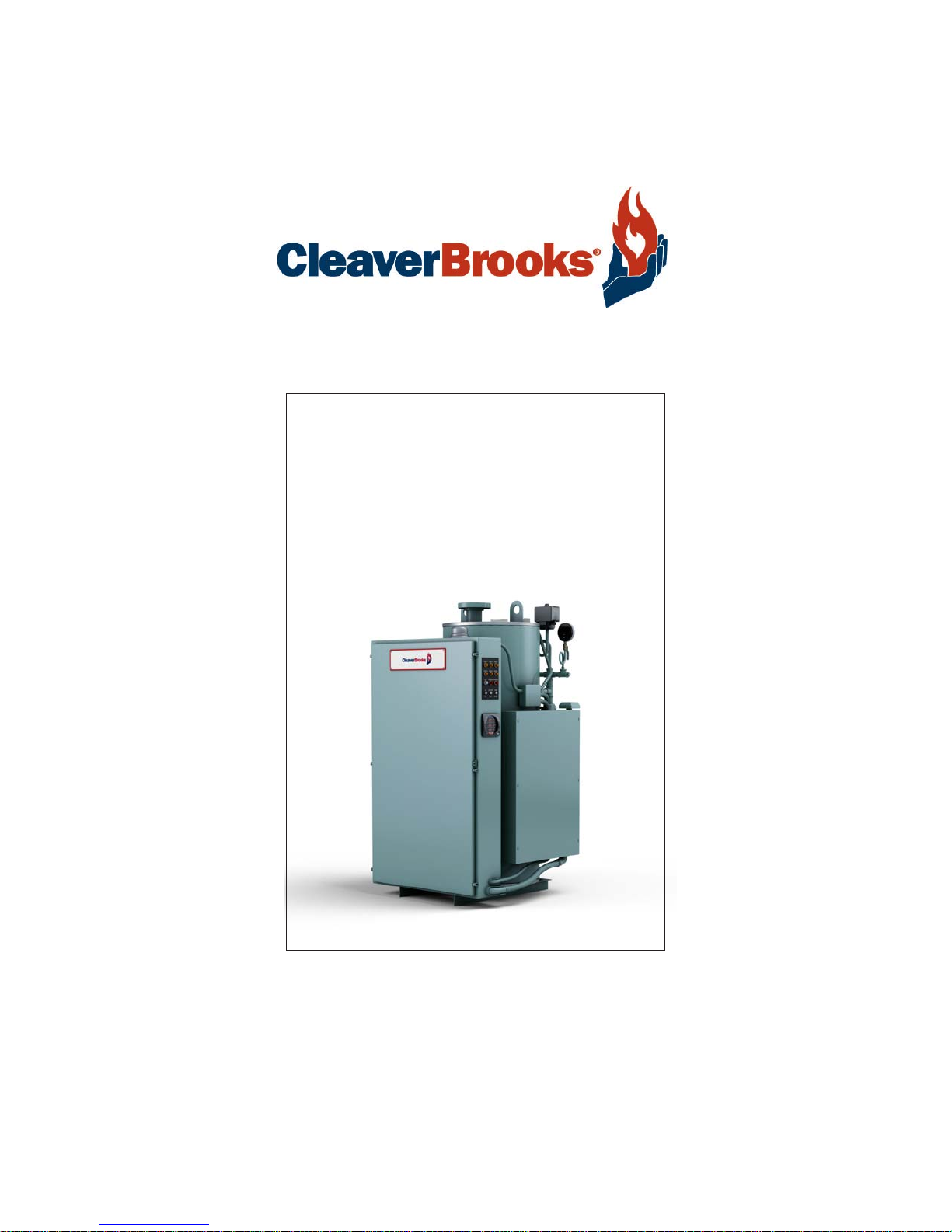
Models S, CR & HSB
Electric Boilers
Steam
Operation and Maintenance Manual
750-137
11/2012
Page 2

Page 3

CLEAVER-BROOKS
Models S, CR & HSB
Electric Boilers - Steam
Operation and Maintenance Manual
Cleaver-Brooks 2012
Please direct purchase orders for replacement manuals to your local Cleaver-Brooks authorized representative
Manual Part No. 750-137
11/2012
Printed in U.S.A.
Page 4

!
WARNING
DANGER
DO NOT OPERATE, SERVICE, OR REPAIR THIS EQUIPMENT UNLESS YOU FULLY UNDERSTAND ALL
APPLICABLE SECTIONS OF THIS MANUAL.
DO NOT ALLOW OTHERS TO OPERA TE, SER VICE, OR REP AIR THIS EQUIPMENT UNLESS THEY FULL Y
UNDERSTAND ALL APPLICABLE SECTIONS OF THIS MANUAL.
FAILURE TO FOLLOW ALL APPLICABLE WARNINGS AND INSTRUCTIONS MAY RESULT IN SEVERE
PERSONAL INJURY OR DEATH.
This instruction and maintenance manual presents information that will help to properly operate and care for
the equipment. Study its contents carefully. The unit will provide good service and continued operation if
proper operating and maintenance instructions are followed.
Cleaver-Brooks boilers are designed and engineered to give long life and excellent service on the job. The
electrical and mechanical devices supplied were chosen because of their known ability to perform, however,
proper operating techniques and maintenance procedures must be followed at all times. Although these
components afford a high degree of protection and safety, operation of the equipment is not to be considered
free from the hazards inherent in handling electricity, pressurized hot water, and steam.
It is solely the operator’s responsibility to properly operate and maintain the equipment. No amount of written instructions can replace intelligent thinking and reasoning and this manual is not intended to relieve the
operating personnel of the responsibility for proper operation or the application of timely preventive maintenance.
It is recommended that a boiler room log or other permanent record be maintained. Recordings of daily,
weekly, monthly, and yearly maintenance activities and recording of may unusual operation will serve as a
valuable guide to any necessary investigation.
It is customary to engage the services of a qualified water treatment company or a water consultant to recommend the proper water treating practices. Contact your local Cleaver-Brooks authorized representative for
details about Cleaver-Brooks water treatment services.
The operation of this equipment must comply with all requirements or regulations of the insurance company
and/or any other authority having jurisdiction. These legal requirements take precedence over anything contained herein.
Page 5

Model S, CR & HSB Electric Boilers
Table of Contents
CHAPTER 1 General Description 1-1
1.1 — Introduction 1-1
1.1.1 — Safety Precautions 1-1
1.1.2 — Abbreviations 1-2
1.2 — Application 1-2
1.3 — Description 1-2
1.4 — Principles of Operation 1-5
CHAPTER 2 Installation Instructions 2-1
2.1 — Receiving Inspection 2-1
2.2 — Location 2-1
2.3 — Piping 2-1
2.4 — Electrical 2-2
2.4.1 — Electrical Installation Checklist 2-3
2.4.2 — Recommended Torque Settings 2-4
CHAPTER 3 Pre-Start Preparation 3-1
3.1 — Inspection 3-1
3.2 — Boiler and System Cleaning 3-2
3.3 — Boiler Water Treatment 3-3
750-137 (revised 2012)
Model S, CR & HSB Electric Boiler Manual
i
Page 6

CHAPTER 4 Operating Instructions 4-1
4.1 — Initial Startup 4-1
4.2 — Control Adjustment 4-2
4.2.1 — Pressure Control Setup 4-2
4.3 — Blowdown 4-3
4.3.1 — Vessel Blowdown 4-3
4.3.2 — Gauge Glass Blowdown 4-3
4.3.3 — Water Level Control Blowdown 4-4
4.4 — Maintenance 4-4
4.4.1 — Quarterly Procedure 4-4
4.4.2 — Annual Procedure 4-5
4.5 — Element Replacement Procedure 4-5
4.5.1 — Replacement of Individual Elements 4-6
CHAPTER 5 Troubleshooting 5-1
5.1 — Problems, Causes, and Actions 5-1
CHAPTER 6 Parts 6-1
ii
750-137 (revised 2012)
Model S, CR & HSB Electric Boiler Manual
Page 7
CHAPTER 1 General Description
1.1 — Introduction
1.1.1 — Safety Precautions
A complete understanding of this manual is required before attempting to operate or maintain the equipment.
It is essential to read and understand all safety precautions before attempting to operate the equipment.
Failure to follow these precautions may result in damage to equipment, serious personal injury, or death.
The equipment should be operated and maintained only by personnel who have read this manual and who have
a working knowledge and understanding of the equipment.
Warning
!
Warning indicates a potentially hazardous situation which, if not avoided, could result in serious injury or death.
Caution
!
Caution indicates a potentially hazardous situation which, if not avoided, could result in damage to the equipment.
NOTE: ”NOTE:” indicates information that is vital to the operation of the equipment.
750-137 (revised 2012)
Model S, CR & HSB Electric Boiler Manual
1-1
Page 8

1.1.2 — Abbreviations
Following is an explanation of the abbreviations, acronyms, and symbols used in this manual.
Abbreviation Explanation Abbreviation Explanation
ASME American Society of Mechani-
cal Engineers
AR Automatic Reset MR Manual Reset
BHP Boiler Horsepower pH Measure of the degree of acid
BTU British Thermal Unit P/N Part Number
C Degree Celsius PPB Parts Per Billion
F Degree Fahrenheit PPM Parts Per Million
GPM Gallons Per Minute PSI Pounds Per Square Inch
Ht Height T Temperature
Hz Hertz TC Temperature Control
KW Kilowatt TI Temperature Gauge
Lb Pound wsi Watts Per Square Inch
LWCO Low Water Cut Off
or base of a solution
General Description
1.2 — Application
The Cleaver-Brooks models S, CR & HSB are Immersion Element Steam Boilers designed for the heavy duty, continuous demand of commercial and industrial applications. They can be used as a primary, supplementary, or
auxiliary source of stem for space and process heating. The model HSB comes equipped with a 75 wsi Incoloy
element. The models S and CR come equipped with a 67 wsi Incoloy element. Some 600v models are equipped
with a 78 wsi Incoloy element.
1.3 — Description
Typical Cleaver-Brooks Models S, CR & HSB Steam Boilers are shown in Figures 1-1, 1-2, and 1-3. Illustrated
are packaged steam boilers with either horizontal or vertical insulated vessels. The boilers include control cabinets mounted on a common base and operating controls, elements, fuses, contactors, safety valve, and instrumentation. All boilers are wired, piped, tested, and ready for installation.
The vessel construction complies with ASME Boiler & Pressure Vessel Code: either Section I, “Power Boilers,” or
Section IV, “Low Pressure Heating Boilers.” Section I vessels are either “M” stamped for 100 psi design and up
to 90 psi operating pressure (models S & CR-120 through 162) or “S” stamped for operation and design pressures of 125 psi or more. Section IV vessels have the “H” stamp for 15 psi design for 13 psi maximum operating
pressure. All boilers are National Board inspected and registered, and are UL listed.
Refer to the Dimension Diagram (DD) and Wiring Diagram (WD) prepared by Cleaver-Brooks for your specific
installation.
1-2
750-137 (revised 2012)
Model S, CR & HSB Electric Boiler Manual
Page 9

1.3 — Description
The following items are standard on all Cleaver-Brooks Electric Steam Boilers.
Component Description
1. Main Lugs for Supply Circuit Standard boilers are supplied with solderless wire connectors suitable for
copper supply wires. The main lugs are mounted on distribution busses
that provide individual connections for each heating element circuit. Standard boilers are designed for top connection to main power supply.
2. Supplemental Internal Protection
Fuses
3. Built-In Magnetic Contactors All boilers use definite purpose magnetic contactors designed for use with
4. Heating Elements Standard heating elements are Incoloy sheathed and rated at 75 watts
5. 120 Volt Control Circuit All boilers have 120 volt control circuits. Control circuit transformers with
6. Customer Control Interlock Con-
nection
7. High Pressure Cutoff All standard boilers with more than 2 control steps are supplied with one
8. Water Level Controller/Low Water
Cutoff
Boilers are provided with supplemental internal protection fuses rated at
approximately 125% of the element circuit load. These current-limiting
cartridge fuses have a minimum 200,000 ampere interrupting capacity to
provide protection for the element circuit wiring.
resistance heating loads. Contactors are rated for at least 50 amps resistive load and a minimum of 500,000 duty cycles.
per square inch (model HSB), or 67 or 78 wsi (models S and CR). These
elements are individually replaceable.
primary fusing and grounded secondary are provided on all models,
except when the customer specifies a 208/120 volt, 3-phase, 4-wire configuration. All boilers have 120 volt control circuits and are available for
either 50 or 60 Hz.
A terminal slip is provided on all boilers for connection of the customer’s
control devices and interlocks.
automatic-resetting and one manual-resetting high pressure cutoff. These
normally are set at 10% and 5% below the safety valve set pressure
respectively, unless otherwise specified. On smaller boilers, one autoresetting high pressure cutoff is standard as a backup to the limit duty
rated pressure control.
An automatic resetting, float type, combination low water cutoff and
water level controller is installed on each Cleaver-Brooks electric steam
boiler. If the vessel water level drops, the controller closes a switch, which
may be used to operate either a feed-pump relay or feedwater solenoid
valve. If the water level drops below the cutoff level, the heating elements
are de-energized by the controller until the water level returns to operating
level.
750-137 (revised 2012)
Model S, CR & HSB Electric Boiler Manual
1-3
Page 10

General Description
Component Description
9. Pressure Control System Boilers with 1 and 2 stages of control are standardly provided with on-off
pressure controls. Larger boilers are provided with a solid state, proportional, modulating step-type pressure control system. As the system
steam pressure varies, the pressure control system proportions the input
power to the boiler demand, by increasing (or decreasing) the number of
heating element groups (steps) in use.
Both control systems (on-off and proportional) have adjustable pressure
ranges. The on-off controls have fixed differentials. The proportioning controls have adjustable proportioning ranges.
This proportional solid state electronic sequencers also have an adjustable
time delay between steps varying from 5 seconds up to 10 minutes.
These adjustable controls enable the boiler to be tuned to the system it
regulates in order to optimize boiler responsiveness and system operation.
The controller features rapid recycling after power interruption. When
power is restored, the boiler starts with all elements off. To prevent current surges, the step control ensures that the element groups are switched
on, one at a time.
10. Pilot Switch and Pilot Lights Pilot lights are standardly provided to indicate “power on,” “high pressure,” and “low water.”
11. Safety Valve The safety valve is properly sized according to the boiler’s electrical rating
and per ASME and National Board.
12. Built-In Condensate/make-Up
Tank and Feedpump (model CR boilers only)
This includes a condensate return tank and feedwater pump, completely
wired and piped. The condensate return tank is provided with a float-type
make-up valve, drain valve, and the necessary condensate return, vent,
and overflow connections.
The following optional equipment can be furnished by Cleaver-Brooks. The Dimension Drawings (DD) and Wiring
Diagrams (WD) shows the optional boiler equipment:
1. Manual reset low water cutoff
2. Auxiliary low water cutoff (manual or auto-reset)
3. Low pressure alarm
4. Pilot lights for individual steps
5. Toggle switches to enable/disable individual steps
6. Solid state progressive sequencing step control
7. Preheat switch
8. Demand limiting controls or interface
9. Control cabinet door interlock
10. Boiler disconnect switch or circuit breaker (with or without shunt trip, shipped loose for field mounting)
11. Ground fault detection
12. Metering ammeter, voltmeter or KWH meter
13. Alarm circuit (with or without horn/silence push button)
14. Automatic surface blowdown system
15. Local/remote modulation switch
16. SCR controller
1-4
750-137 (revised 2012)
Model S, CR & HSB Electric Boiler Manual
Page 11

1.4 — Principles of Operation
17. Feedwater valve
18. Other miscellaneous options
1.4 — Principles of Operation
Immersion element steam boilers consist of a number of resistance-type heating elements assembled within a
pressure vessel. Electrical power applied to these elements is converted into heat and conducted into the surrounding water. Steam bubbles form at the element surface and then rise to the steam place at the top of the
vessel.
Controls are provided in order to match the input of electricity with the load requirements of the system. Heating
elements are switched on and off by magnetic contactors in response to the pressure control system. The simplest pressure control consists of a single pressure activated switch that energizes all heating elements simultaneously. This on-off control is suitable for small steam boilers (single stage). For 2-stage boilers, two pressure
controls are used to provide on-off switching of selected element groups at different settings.
The close control of boiler output demanded by large, complex, or critical steam systems requires the use of fully
modulating step controls. To proportion input power to steam demand, these modulating step controls select the
number of heating element groups, or steps, in sequence, in order to maintain the desired steam pressure.
750-137 (revised 2012)
Model S, CR & HSB Electric Boiler Manual
1-5
Page 12

General Description
1-6
750-137 (revised 2012)
Model S, CR & HSB Electric Boiler Manual
Page 13

CHAPTER 2 Installation Instructions
Warning
!
Installation should be performed only by qualified personnel who are familiar with this equipment. Failure to heed
this warning may result in serious personal injury or death.
Before proceeding, make sure you have read and understand the contents of this manual. Failure to do so may result
in serious personal injury or death.
2.1 — Receiving Inspection
Each Model S, CR and HSB boiler is completely inspected at the factory and carefully packaged for shipment.
Inspect the packing for signs of exterior damage. After placing the unit as close as possible to the point of actual
installation, carefully uncrate and check all boxes and cartons against the packing slip. In case of damage or
shortage, notify the carrier immediately.
2.2 — Location
Consult local codes for specific requirements. Refer to the Dimension Drawings (DD) and Wiring Diagram (WD)
prepared by Cleaver-Brooks for your specific installation. Position the boiler to provide adequate clearance on all
sides for necessary access when operating and servicing the boiler.
Set the boiler on a strong foundation and make sure it is level. The boiler must be level so that the water gauge
glass indicates the true water level and so that the water level controller functions properly.
2.3 — Piping
Install the steam and water lines according to the job requirement.
750-137 (revised 2012)
Model S, CR & HSB Electric Boiler Manual
2-1
Page 14

Installation Instructions
The steam piping from the boiler to the point of steam use must be pitched to assure proper drainage of condensate formed in the steam line. If possible, pitch the horizontal runs away from the boiler and provide a drip leg at
the end of the run and at any other low points so that the condensate runs away from the boiler.
A condensate return line must be installed with a minimum pitch of 1/4” per foot toward the condensate
receiver.
When a direct water feed is used, the water supply main must have a pressure of at least ten pounds greater
than the maximum pressure at which the boiler is to be operated. A solenoid valve is usually required to control
the flow of feedwater to the boiler. Solenoid valves should be sized to feed the boiler at twice the steaming rate
(#/hr. divided by 500 = steaming rate in gpm). The coil should be the same voltage as the boiler control circuit
(refer to the Wiring Diagram).
Warning
!
Discharge from the boiler blowdown and safety valves is hot and could burn or scald personnel. It is of the utmost
importance that these valves are piped to a safe point of discharge, and that pipes are insulated or guarded to prevent burns due to accidental contact, serious personal injury, or death. The piping for all blowdown must be the same
size as the blowdown valve.
NOTE: These water and steam pipe installation instructions are for your guidance only. In all piping installations, be
sure to check that the piping is in accordance with applicable federal, state, and local codes, regulations, and other
statutory requirements.
It is recommended that a vacuum breaker be installed in the steam line when a condensate return system is
being used. The breaker will prevent flooding of the boiler during shutdown.
2.4 — Electrical
Warning
!
Lockout and disconnect main power before proceeding with electrical installation in order to avoid the hazard of electrical shock, which could cause serious personal injury or death.
The procedures listed here are based on requirements of the National Electrical Code. Local electrical codes and/
or boiler codes may require slightly different procedures. It is therefore recommended that the electrical installation be performed under the supervision of a qualified and licensed electrical contractor familiar with local codes
and inspection procedures.
Typical electric steam boilers are designed for top connection to the main supply lugs and are supplied with solderless wire connectors suitable for copper supply wires.
• The main supply lugs should be tightened (with power off) every 24 hours for the first week of operation.
• After the first 30 days of operation, all electrical power connections should be tightened (with power off).
2-2
750-137 (revised 2012)
Model S, CR & HSB Electric Boiler Manual
Page 15

2.4 — Electrical
If aluminum supply wires are selected, Cleaver-Brooks strongly recommends that the installing electrical contractor splice a short length of copper wire to the aluminum supply conductors and terminate this copper wire in the
main supply lugs on the unit. If copper splices are not used and the customer chooses to terminate the aluminum
supply wires directly in the main supply lugs, the following points should be carefully followed:
• An oxide inhibitor paste should be applied liberally to the conductors.
• The main supply lugs should be tightened (with power off) every 24 hours for the first week of operation.
• After the first week, the main supply lugs should be tightened (with power off) once every 30 days.
•
After the first 30 days of operation, all electrical power connections should be tightened (with power off).
Warning
!
Before tightening the main supply lugs, lockout and disconnect the main power to avoid the hazard of electrical
shock, which could cause serious personal injury or death.
Caution
!
Main supply lugs should be tightened every 24 hours during the first week of operation in order to avoid damage to
the equipment. After the first week, the main supply lugs should be tightened (with power off) once every
30 days.
After the first 30 days of operation, all electrical power connections should be tightened (with power off).
Power wiring should be selected for high temperature use (minimum wire rating, 75 deg. C per National Electrical Code) and/or per local electrical codes.
2.4.1 — Electrical Installation Checklist
1. Check all electrical connections for tightness. Vibration during transit sometimes loosens connections. See
Section 2.4.2 for recommended torque settings.
2. Check the boiler nameplate for the boiler kilowatt rating, frequency, voltage, amperage, and to determine
whether it is single or three-phase.
3. Check the electrical supply voltage to verify that it conforms to the boiler requirements, and that sufficient cir-
cuit capacity is available for the boiler.
4. Refer to the Wiring Diagram (WD) prepared by Cleaver-Brooks for your specific installation for the number and
rating of supply circuits required by the boiler.
5. Refer to the Wiring Diagram (WD) prepared by Cleaver-Brooks for your specific installation for proper wire and
conduit sizes for these ratings.
6. Install the wiring to the boiler and connect it to the main supply lugs as indicated on the boiler Wiring Diagram
(WD).
7. All Cleaver-Brooks electric steam boilers are supplied with factory-mounted magnetic contactors. All internal
circuits are factory installed and tested.
8. The external solenoid valves for the feedwater supply may be connected to the boiler control circuit. Refer to
the boiler Wiring Diagram (WD) for details and voltage.
750-137 (revised 2012)
Model S, CR & HSB Electric Boiler Manual
2-3
Page 16

Installation Instructions
9. If an external feedwater pump is to be used, it will require a separate electrical supply circuit and a magnetic
motor starter (coil not to exceed 25-VA). This circuit can be controlled through the unit control circuit. CR
Series boilers have built-in boiler feed pump and controls.
10. Upon completion of all installation work, recheck all of the connections for tightness and test for correct con-
trol circuit operation as described in Chapter 4 of this manual. See Section 2.4.2 for recommended torque
settings.
Warning
!
To avoid the hazard of electrical shock: On boilers requiring more than one supply circuit, be sure that phasing is correct and circuits are not “mixed” before energizing. Failure to obser ve this warning could cause serious personal
injury or death.
2.4.2 — Recommended Torque Settings
The following table notes typical torque settings only, as recommended by Cleaver-Brooks. Specific components
may differ between boilers. ALWAYS adhere to each component’s recommended torque setting for specific wire
size and type (often located on component’s factory label).
Recommended torque settings
Electric boilers - main control panel
Power distribution blocks (6AWG - load side) 45 in lbs
Fuse blocks for contactors (6AWG) 45 in lbs
Contactor, 50A res. (6AWG - line side) 45 in lbs
Contactor, 50A res. (8AWG - load side) 40 in lbs
Caution
!
Specific components may differ between boilers. ALWAYS adhere to each component’s recommended
torque setting for specific wire size and type (often located on component’s factory label).
2-4
750-137 (revised 2012)
Model S, CR & HSB Electric Boiler Manual
Page 17

CHAPTER 3 Pr e-Start Pr eparation
Warning
!
Before proceeding, make certain Chapters 1 and 2 of this manual have been read and understood. Failure to do so
may result in serious personal injury or death.
Pre-startup should be performed by a qualified technician who is familiar with this equipment. Failure to heed this
warning may result in serious personal injury or death.
3.1 — Inspection
Boilers which have been exposed to dust or wet or humid conditions must be thoroughly cleaned and dried out.
The buildup of dust and rust on the contactors or moisture at the terminal end of the elements may result in
severe damage. The following precautions must be taken:
Warning
!
Lockout and disconnect the main power to avoid the hazard of electrical shock, which could result in serious personal
injury or death.
1. Make certain all electrical connections and element terminals are thoroughly cleaned, dried, and tightened.
2. Inspect all contactors, fuse bases, and wire bundles for stray or loose metal objects (screws, bolts, metal
shavings, knockout slugs, etc.) that may lodge there. All such material must be removed before startup.
3. The elements may accumulate moisture during shipment or storage prior to operation. This moisture will turn
to steam when the elements are turned on, rupturing the element casing.
Caution
!
Moisture in the elements may result in damage to the elements.
750-137 (revised 2012)
Model S, CR & HSB Electric Boiler Manual
3-1
Page 18

Pre-Start Preparation
Warning
!
Lock out and disconnect the main power to avoid the hazard of electrical shock, which could result in serious personal injury or death.
To check for this condition, take a reading with an ohmmeter between one of the contactor terminals (load side)
to ground for each contactor. If the reading is less than 17,000 ohms for a standard 3-phase connection, or
50,000 ohms for a single element, remove the fuses going to that contactor. The fuses should be removed so
that, during the first day of operation, the affected element will not be energized, allowing the hot boiler to drive
the moisture out at a controlled rate.
There are alternate heating methods. Direct a heat lamp at the offending elements or remove the element assembly, bake it in a 200º F oven for 8 hours, then reinstall and rewire. Following any of these procedures, the suspect element then may be put in operation by replacing the fuses after the elements have been rechecked with
an ohmmeter.
3.2 — Boiler and System Cleaning
The entire steam system must be cleaned prior to startup. No matter how carefully a system is installed, it will
be contaminated with pipe dope, thread cutting oils, soldering flux, rust preventatives, core sand, welding slag,
and dirt, sand, or clays.
Cleaning a how water system (either steel or copper piping) is neither difficult nor expensive. The three most
common materials used for cleaning are (in order of preference):
• Trisodium Phosphate (TSP)
• Sodium Carbonate
• Sodium Hydroxide (lye)
Prepare the cleaning solutions as follows, DO NOT mix together different types of cleaners.
Material Specifications
Trisodium Phosphate (TSP) one lb. for every fifty gallons in the system
NOTE: Check local codes for restrictions on the use of TSP.
Sodium Carbonate one lb. for every thirty gallons in the system
Sodium Hydroxide (lye) one lb. for every fifty gallons in the system
NOTE: Do not use Sodium Hydroxide for copper or galvanized systems.
Cleaning compounds are hazardous and personal protective equipment must be used when mixing or handling chemicals and chemical solutions in order to avoid possible serious personal injury or death.
3-2
Warning
!
750-137 (revised 2012)
Model S, CR & HSB Electric Boiler Manual
Page 19

3.3 — Boiler Water Treatment
Fill, vent, and circulate the system with one of the solutions, allowing it to reach operating temperatures, if possible. After circulating for three hours, drain the system completely and refill it with fresh water. Usually enough
of the cleaner will adhere to the piping to give an alkaline solution satisfactory for operation. A pH reading
between 8.5 and 9.5 is preferred, and a small amount of cleaner can be added, if necessary, to raise the pH
value.
There are definite indications of an unclean system. If any of the following conditions are present when filling the
system, the boiler and associated system piping need cleaning:
• Obviously discolored, dirty water.
• A pH or alkalinity test that gives a pH test reading below 7 (below 7 indicates the water in the system is acidic
and corrosive).
• The appearance of dirty foam or scum lines on the surface.
In some cases, there are sufficient quantities of such materials to break down chemically during the operation of
the system causing gas formation and acidic system water. All such materials should be removed.
Steam systems, in most cases, naturally operate with a pH of 8.5 or higher. If a system indicates pH values
below 7 on the scale the following conditions may be present:
• Gas formation in the system.
• Pump seal and gland problems.
• Air vent sticking and leaking.
• Piping leaks at the joints.
If system deterioration is permitted and leaks develop and water losses increase, it is possible to cause serious
damage to the boiler. Therefore, it is important to have a closed system that is clean, neutral, and water tight.
3.3 — Boiler Water Treatment
The recommended water quality to facilitate keeping the boiler clean and to prevent corrosion and scaling is:
pH 8.3 - 10.5
Iron 0.1 PPM maximum
Alkalinity <600 PPM maximum
Chlorides 30 mg/liter maximum
Oxygen 0.1 mg/liter maximum
Specific Conductivity 4500 mmho/cm
Total Hardness <3 PPM maximum
These recommended guidelines do not include all dissolved minerals. For more information about maintaining
water quality, contact your Cleaver-Brooks local representative.
The purchaser should be sure that the boiler is not operated for long periods for approval tests, temporary heat,
or any other operations without water treatment. It also should be noted that water boilers will need chemical
treatment for the first filling of water and additional periodic chemical treatment.
750-137 (revised 2012)
Model S, CR & HSB Electric Boiler Manual
3-3
Page 20

Pre-Start Preparation
Water treatment may vary from season to season or over a period of time; therefore, there should be a requirement that the water treatment procedure be checked no less than four times a year, and possibly more frequently, as the local water conditions may require.
3-4
750-137 (revised 2012)
Model S, CR & HSB Electric Boiler Manual
Page 21

CHAPTER 4 Operating Instructions
Warning
!
Make certain all startup procedures listed in Chapter 3 have been completed prior to proceeding.
Before gaining access to any electrical wiring or controls, disconnect and lockout the main power to the boiler to
avoid the hazard of electrical shock, which could result in serious personal injury or death.
4.1 — Initial Startup
1. Close the control cabinet doors.
2. Close all blowdown valves and steam outlet valves, including the gauge drain valves and the water level con-
troller.
3. Close the main power switch(es).
4. Turn on the pilot switch to energize the control circuit. Both the white “power on” and the red “low water”
pilot lights will light.
5. Monitor the gauge glass until the water nears the halfway mark on the glass and the red, low water alarm
light de-energizes.
NOTE: On CR model boilers the boiler feed pump may be capable of pumping water from the condensate receiver
into the boiler faster than the make-up water feeder can handle. Therefore, on initial startup of the CR boilers, it may
be necessary to fill the boiler vessel by intermittently turning the pilot switch off and on to allow the make-up water
feeder in the boiler condensate receiver to catch up. Under normal operation, when condensate is being returned to
the receiver, the make-up feeder will adequately maintain the water level in the receiver.
6. Listen for the contactors to snap closed, which indicates that the elements are being energized.
7. Monitor the pressure and the water level.
8. When the pressure reaches the operating setting of the pressure controller, the contactors will start to drop
out.
9. The boiler now can be placed in service by slowly opening the steam outlet valve. Adequate draining and slow
warming of the piping will help to avoid water hammer and excessive temperature gradients in the piping.
750-137 (revised 2012)
Model S, CR & HSB Electric Boiler Manual
4-1
Page 22

Operating Instructions
4.2 — Control Adjustment
The operating pressure and the high pressure limits have been set at the factory to comply with the customer’s
specifications and normally do not require resetting. However, the demands upon your particular boiler may
require some deviation from the factory settings. If adjustments are necessary, use the following information as a
guide.
FIGURE 4-1. Pressure Control Unit
4.2.1 — Pressure Control Setup
Adjustments are made using the knobs on the front of the controller.
High Limit Setpoint
The SETPOINT setting determines the pressure value at which safety shutdown will occur. NOTE: The high limit
setpoint value can be less than or equal to the Maximum Fixed Stop Limit value (factory set at the maximum
allowable working pressure of the vessel) but cannot exceed this value.
On/Off Control
When pressure increases to the SETPOINT, the control relay contacts open. The relay contacts close when the
pressure decreases to a level equal to the setpoint minus the DIFFERENTIAL.
Modulate
When the pressure decreases to the modulation SETPOINT, the controller output current will be 20 mA. The current remains constant at all pressures below the modulation setpoint.
When the pressure increases above the modulation setpoint, the current decreases linearly until the modulation
RANGE point is reached. The output current will be 4 mA at and above this pressure.
4-2
750-137 (revised 2012)
Model S, CR & HSB Electric Boiler Manual
Page 23

4.3 — Blowdown
NOTE: Boiler controls may vary depending on boiler model. Consult
the appropriate literature for information specific to your application.
4.3 — Blowdown
Initially, blowdowns (bottom and water column) should be performed daily until experience suggests otherwise.
Where low pressure steam boilers are used solely for heating, and where practically all of the condensate is
returned to the boiler, blowdown only as often as concentration of solids requires. Boilers used for process steam
that require high make-up should be blown down frequently to maintain chemical concentrations at the required
levels and to remove precipitated solids.
4.3.1 — Vessel Blowdown
1. Allow the boiler to attain full steam pressure.
2. Turn off the pilot switch.
3. Open the vessel blowdown valve to the full open position to allow the water to escape as rapidly as possible in
order to remove the sediment.
4. Close the blowdown valve.
5. Allow the boiler to refill. When the water is near the normal operating level, re-close the pilot switch.
NOTE: Most element failures are caused by neglect to regularly blowdown.
Blowdown the vessel as necessary to maintain the recommended levels of total dissolved solids.
4.3.2 — Gauge Glass Blowdown
The water gauge glasses should be kept clean. Dirt on or in the gauge glass may be mistaken for the water level.
To clean or blowdown the gauge glass, the boiler should be at its operating pressure.
1. Fully close both the top and bottom gauge glass isolation valves.
2. Open the drain cock.
3. Open the top valve briefly to purge the dirt and debris from the piping, then close.
4. Open the bottom valve in the same manner as step “3,” then close.
5. Close the drain cock on the bottom valve.
6. Crack the top valve just enough to allow the slow passage of pressure. When the flow has ceased, fully open
the valve.
7. Crack the bottom valve just enough to allow the slow seepage of water to enter the glass.
8. Continue to crack the bottom valve until the water level stabilizes. Then slowly open the valve to its full posi-
tion.
750-137 (revised 2012)
Model S, CR & HSB Electric Boiler Manual
4-3
Page 24

Operating Instructions
4.3.3 — Water Level Control Blowdown
Caution
!
Be sure to flush your low water cutoff DAILY in order to avoid damage to the equipment.
The float type combination water level control and the low water cutoff must also be flushed while the boiler is in
operation. Open the blowoff valve on the water column, draining the water from the control. Close the valve. To
check the operation of the water level control and the low water cutoff, slowly open the blowoff valve on the
boiler and drain the water just below the bottom of the sight glass. If the magnetic contactors do not turn off, the
low water cutoff should be checked. Close the valve. The water level should be restored automatically.
Caution
!
Do not leave the magnetic contactors on after the water recedes from the sight gauge. To do so may result in damage
to the equipment.
4.4 — Maintenance
4.4.1 — Quarterly Procedure
Warning
!
Lockout and disconnect the main power before tightening the main supply lugs in order to avoid the hazard of electrical shock, which could result in serious personal injury or death.
Tighten the main supply lugs every 24 hours during the first week of operation.
1. While the boiler is operating, lower the pressure setting drastically on the control pressure and listen for the
magnetic contactors to open. Then return the setting to normal and again listen for the magnetic contactors to
close.
2. Turn off the control pilot switch and the main power supply switch. This is a safety measure to prevent acci-
dental turn-on of power.
3. Tighten all the electrical connections that could have loosened due to heat expansion and contraction. Pay
particular attention to the main lugs that receive the power circuit. Examine all the relays and the magnetic
contactors for pitting, corrosion, burned or welded contacts, or inoperative 120-volt coils. INspect for blown
fuses or discoloration of fuse clips, which would indicate a loose fit. Correct malfunctions as required. If the
boiler was supplied with a probe-type auxiliary low water cutoff, remove the low water cutoff probe from the
vessel, clean the probe, and reinstall it.
When checking the element terminal connections, use a wrench on both nuts to avoid twisting the terminal stud and
damaging the equipment.
If all elements have been operating normally and each element bank draws its rated current or amperage, where
4-4
Caution
!
750-137 (revised 2012)
Model S, CR & HSB Electric Boiler Manual
Page 25

4.5 — Element Replacement Procedure
AMPS (3 phase) = Watts
Volts x 1.73
or
AMPS (1 phase) =
Watts
Volts
no further element tests are necessary.
However, if there is a low or unbalanced amp reading, further tests with an ohmmeter may be necessary to
detect the open or shorted elements in the group. To test individual elements for continuity with an ohmmeter,
the jumpers between elements must first be removed.
4.4.2 — Annual Procedure
The boiler should be drained and cleaned to remove any accumulated scale or sludge. This normally can be done
concurrently with an annual inspection. More frequent cleaning may be required if the boiler supply water contains sediment or if a considerable amount of make-up water is used to replace system losses. The annual checkout and startup procedure is otherwise identical with the quarterly procedure.
4.5 — Element Replacement Procedure
The individually replaceable electric heating elements are readily accessible for fast, easy, on-the-job maintenance. They can be removed and replaced with standard tools. The small physical size of each element means
the element bundle is lighter and simpler to remove.
Warning
!
Before element replacement, lockout and disconnect the main power. Also, before element replacement, make certain the boiler is cooled to an ambient temperature before draining below the element opening. Failure to heed this
warning could result in serious personal injury or death.
750-137 (revised 2012)
Model S, CR & HSB Electric Boiler Manual
4-5
Page 26

4.5.1 — Replacement of Individual Elements
Operating Instructions
FIGURE 4-2. Heating Elements
1. Make a sketch or a drawing of the element bussing and label the wires in order to simplify later reconnection.
Refer to wiring diagram provided by Cleaver-Brooks for your installation.
2. Disconnect the wires and remove the element assembly flange bolts.
NOTE: To assist in breaking free the gasket, insert one of the flange bolts into the tapped hole provided.
3. Remove the element assembly by pulling it straight out.
4. Remove the jumper wires and the brass ferrule nuts from the element.
5. Slide the element toward the dry side (about 2”) to expose the brass ferrules on the element. Cut off the fer-
rules with a hacksaw. Slide the element out of the steel flange toward the wet side.
6. Inspect and clean the thread and the seat of the steel flange where the new ferrule will seal. If the seats are
pitted or rusted, it will be impossible to seal the new elements. Therefore, a new flange may be required.
7. Screw the new ferrule nuts (these are furnished with the replacement element) into the cleaned or new flange
plate (finger tight).
8. Slide the element into position. Make sure the element protrudes beyond the ferrule nut approximately 1/4”,
or to match the original assembly. Some boiler models require the element sheath to extend out further than
1/4”, so duplicate the original assembly as closely as possible.
NOTE: Since the elements often differ in length, check to assure that there is an adequate clearance (3/4” min.)
between the end of the element and the opposite side vessel wall. Check by measuring both the element extension
(from flange to tip) and the distance from the tank flange face to the vessel wall.
4-6
750-137 (revised 2012)
Model S, CR & HSB Electric Boiler Manual
Page 27

4.5 — Element Replacement Procedure
9. Hold the element to prevent twisting while tightening the ferrule nuts. Tighten the nuts to approximately 45 ft.
lbs. (35 ft. lbs. for 208 and 240 Volt elements). You will feel the ferrule separate from the nut while tightening. A properly tightened ferrule nut will have separated from its ferrule and the ferrule will be squeezed or
compressed onto the element sheath, thus providing a tight seal.
10. Replace the element assembly into the boiler, using a new gasket and anti-seize compound on gaskets and
bolts. Torque the element flange bolts to 90 - 100 ft. lbs.
11. When the boiler is filled and pressurized, inspect for leaks. If leaks are detected around the brass ferrules,
tighten the nuts in 5 ft lb increments up to a maximum of 70 ft lb (60 ft lb for 208 and 240 Volt elements)
until leaks are no longer detected.
12. Rewire the element ends. Torque element stud nuts to 35 in lb.
750-137 (revised 2012)
Model S, CR & HSB Electric Boiler Manual
4-7
Page 28

Operating Instructions
4-8
750-137 (revised 2012)
Model S, CR & HSB Electric Boiler Manual
Page 29

CHAPTER 5 T r oubleshooting
5.1 — Problems, Causes, and Actions
Warning
!
Troubleshooting should be performed only by a qualified technician who is familiar with the equipment and who has
read and understands this manual. Failure to heed this warning could result in serious personal injury or death.
During troubleshooting, when possible, disconnect and lockout the main power to avoid the hazard of electrical
shock, which could result in serious personal injury or death.
Problem Possible Cause Action
Pilot switch set to “power on,” pilot
light off.
High pressure/temperature alarm
pilot light on.
• Main power supply not on.
• Control transformer fuse is blown.
• Control transformer inoperative.
• Pilot light burned out.
• Pressure/temperature has
exceeded setpoint on auto reset
limit control.
• Pressure/temperature has
exceeded setpoint on manual
reset limit control.
• Energize power supply.
• Check for loose connections, then
replace fuse.
• Check for proper wiring/loose
connections, replace transformer.
• Check for loose connections,
replace light.
• Allow pressure/temperature to fall
below setpoint less control differential. Raise setting if necessary,
but not above design limit or
manual reset setting.
• Allow pressure/temperature to fall
below setpoint less control differential. Depress reset button.
Raise setting if necessary, but not
above design limit.
750-137 (revised 2012)
Model S, CR & HSB Electric Boiler Manual
5-1
Page 30

Problem Possible Cause Action
Low water alarm pilot light on.
Control power pilot light on, alarm
pilot lights off, contactors not energized.
Steps do not all energize.
Steps do not draw rated current
Contactors noisy (chatter).
• Float-type LWCO: Water below
cutoff line on float cage.
• Float-type LWCO: Float stuck/
switch mechanism jammed.
• Probe-type LWCO: Probe circuit
open/water below cutoff level.
• Probe-type LWCO: Probe or relay
faulty.
• Alarm pilot light(s) burned out.
• Step control fuse blown.
• Pressure/temperature control
improperly wired to step control.
• Step control faulty.
• Contactor coil inoperative.
• Step control relay(s) faulty.
• Branch circuit fuse(s) blown.
• Element bussing improper.
• Element(s) open.
• Contactors damp/dirty.
• Assure unit has proper water
level. Check that LWCO line is at
proper level.
• Check that float blocking plug
has been removed. Perform blowdown of float cage. Assure switch
plate operates freely.
• Check for loose connections/
improper wiring. Assure unit has
proper water level.
• Replace probe or relay.
• Replace pilot light(s).
• Replace fuse.
• Check that wiring is per control
literature and per unit wiring diagram.
• Replace step control.
• Check for loose coil connection.
Replace contactor.
• Check that relay is tight in socket.
Replace relay.
• Check element(s) for proper ohms
and resistance to ground then
replace fuse(s).
• Check that element bussing is per
wiring diagram.
• Replace faulty element(s).
• Blowout contactors with com-
pressed air. Remove contactor,
disassemble and clean, and
replace contactor.
Troubleshooting
5-2
750-137 (revised 2012)
Model S, CR & HSB Electric Boiler Manual
Page 31

CHAPTER 6 Parts
Be sure to furnish complete information when ordering parts. Include the boiler serial number (displayed on the
name plate which is attached to the front of the boiler) on your order. The order should state:
• the Cleaver-Brooks part number
• the name and description of the required part
• the quantity required
• method of shipment
• date the part(s) is needed by
Repair or replacement parts should be ordered from your authorized Cleaver-Brooks representative.
750-137 (revised 2012)
Model S, CR & HSB Electric Boiler Manual
6-1
Page 32

Elements
Part Number Description
129-00100-000 Ferrule Nuts, for 208/240V Heating Elements (.315" ID)
129-00104-000 Ferrule Nuts, for 380/415/480/600V Heating Elements (.475" ID)
129-00409-000 Element Flange Gasket, 8"
129-00204-000 Element Flange Gasket, 10"
Consult Factory for P/N Heating Elements
Contactors
Part Number Description
833-05099-000 Contactor, 50A, 3 Pole
Parts
Fuse Blocks and Fuses
Part Number Description
848-01044-000 Fuse Block, Class T, 3 Pole, 30A, 600V
848-01019-000 Fuse Block, Class T, 3 Pole, 60A, 600V
884-00155-000 Fuse Block, Front-Mounted, Class T, 3 Pole, 60A, 600V
832-01568-000 Fuse Cartridge, Class T, 30A, 600V
832-01371-000 Fuse Cartridge, Class T, 50A, 600V
832-01376-000 Fuse Cartridge, Class T, 60A, 600V
6-2
750-137 (revised 2012)
Model S, CR & HSB Electric Boiler Manual
Page 33

Operating/Modulating/Limit Controls
Part Number Description
817-03186-000 Modulating Pressure Control, 0-15 PSI
817-03187-000 Modulating Pressure Control, 0-150 PSI
817-03188-000 Modulating Pressure Control, 0-300 PSI
817-04094-000 High Limit Control, Manual Reset, 2-15 PSI
817-04092-000 High Limit Control, Manual Reset, 15-150 PSI
817-04149-000 High Limit Control, Manual Reset, 58-250 PSI
817-04095-000 Operating Limit Control, Auto Reset, 2-15 PSI
817-04093-000 Operating Limit Control, Auto Reset, 15-150 PSI
817-04147-000 Operating Limit Control, Auto Reset, 58-250 PSI
997-10815-000 UDC2500 w/ RS-485 Modbus Communication
Step Controllers
Part Number Description
833-03551-000 3-4 Steps
833-03552-000 4-8 Steps
833-03552-000 and 833-03551-000 8-12 Steps (Master and Slave)
833-03552-000 and 833-03552-000 13-16 Steps (Master and Slave)
833-03553-000 and 833-03554-000 17-18 Steps (Master and Slave)
833-03553-000 and 833-03555-000 19-20 Steps (Master and Slave)
833-03553-000 and 833-03556-000 21-22 Steps (Master and Slave)
833-03553-000 and 833-03557-000 23-24 Steps (Master and Slave)
750-137 (revised 2012)
Model S, CR & HSB Electric Boiler Manual
6-3
Page 34

Control Transformers
Part Number Description
832-01801-000 Control Transformer, 500VA, 208V Pri, 120V Sec
832-01910-000 Control Transformer, 500VA, 380/415V Pri, 120V Sec
832-01802-000 Control Transformer, 500VA, 240/480V Pri, 120V Sec
832-01911-000 Control Transformer, 500VA, 600V Pri, 120V Sec
832-01912-000 Control Transformer, 1000VA, 208V Pri, 120V Sec
832-01913-000 Control Transformer, 1000VA, 380/415V Pri, 120V Sec
832-01803-000 Control Transformer, 1000VA, 240/480V Pri, 120V Sec
832-01914-000 Control Transformer, 1000VA, 600V Pri, 120V Sec
832-00235-000 Transformer, Damper, 40VA, 120V Pri, 24V Sec
Parts
Toggle
Switches
Part Number Description
836-00706-000 Toggle, SPST, On-Off
836-00398-000 Toggle, Momentary, SPST, NC
836-00399-000 Toggle, Momentary, SPST, NO
836-00211-000 Toggle, DPDT
Pilot Lights
Part Number Description
881-00249-000 White, Neon Type
881-00250-000 Amber, Neon Type
881-00251-000 Red, Neon Type
Miscellaneous
Part Number Description
997-10943-000 Safety Door Interlock, 115Vac, 60Hz, for single door enclosures
997-00148-000 Safety Door Interlock, 115Vac, 60Hz, for dual door enclosures
817-00239-000 Alarm Bell, 4"
817-00468-000 Alarm Bell, 6"
817-03096-000 Alarm Horn, 4", NEMA 1
836-01461-000 Panel High-Temperature Thermostat Switch
Consult factory for special/custom parts or for parts not shown on this list.
6-4
750-137 (revised 2012)
Model S, CR & HSB Electric Boiler Manual
Page 35

Page 36

e-mail: info@cleaverbrooks.com
Web Address: http://www.cleaverbrooks.com
 Loading...