

CleaverBrooks FLX 150, FLX 250, FLX 200, FLX 400, FLX 450 Operation, Service And Parts Manual
...Page 1
Table Of Contents
$30.00 U.S.
CLEAVER-BROOKS
MODEL FLX
PACKAGED BOILER
Operation, Service, and Parts Manual
1,500,000 to
12,000,000 Btu/hr
Hot Water and
Steam
Fuel: Light Oil, Gas
or Combination
Manual Part No. 750-177 r4
6/2001
Page 2
SAFETY PRECAUTIONS AND
ABBREVIATIONS
Safety Precautions
Abbreviations
Following is an explanation of the abbreviations, acronyms,
and symbols used in this manual.
It is essential to read and understand the following safety
precautions before attempting to operate the equipment.
Failure to follow these precautions may result in damage to
equipment, serious personal injury, or death. A complete
understanding of this manual is required before attempting to
start-up, operate or maintain the equipment. The equipment
should be operated only by personnel who have a working
knowledge and understanding of the equipment.
The following symbols are used throughout this manual:
!
WARNING
DANGER
This symbol indicates a potentially
hazardous situation which, if not
avoided, could result in serious
personal injury, or death.
!
CAUTION
DANGER
This symbol indicates a potentially hazardous situation which, if not avoided, could
result in damage to the equipment.
Note: This symbol indicates information
that is vital to the operation of this
equipment.
AC Alternating Current
AR Automatic Reset
ASME American Society of Mechanical Engineers
ASTM American Society of Testing and Materials
BHP Boiler Horsepower
BTU British Thermal Unit
°C Degrees Celsius
CFH Cubic Feet per Hour
Cu Ft Cubic Feet
DC Direct Current
°F Degrees Fahrenheit
FM Factory Mutual
FS Flame Safeguard
ft Feet
GPM Gallons per Minute
Hd Head
HT Height
HTB High Turndown Burner
HZ He rt z
O Inches of Water
In H
2
IRI Industrial Risk Insurance
Lb Pound
LWCO Low-Water Cut-Off
M Million
MFD Micro-Farad
MR Manual Reset
NEC National Electric Code
No. Number
pH Measure of the degree of acid or base of a
solution
P/N Part Number
PPM Parts Per Million
PR Program Relay
psi Pounds Per Square Inch
SAE Society of Automotive Engineers
scfh Standard Cubic Feet per Hour
T Tempera ture
TC Temperature Control
TI Temperature Gauge
Page 3

MODEL FLX
PACKAGED BOILER
Operation, Service, and Parts Manual
1,500,000 to 12,000,000 Btu/hr
Fuel: Light Oil, Gas or Combination
Cleaver-Brooks 2001
Please direct purchase orders for replacement manuals to your local Cleaver-Brooks authorized representative
Manual Part No. 750-177 R4
Revised 6/2001
Printed in U.S.A.
Page 4

!
WARNING
DANGER
DO NOT OPERATE, SERVICE, OR REPAIR THIS EQUIPMENT UNLESS YOU FULLY UNDERSTAND ALL
APPLICABLE SECTIONS OF THIS MANUAL.
DO NOT ALLOW OTHERS TO OPERATE, SERVICE, OR REPAIR THIS EQUIPMENT UNLESS THEY FULLY
UNDERSTAND ALL APPLICABLE SECTIONS OF THIS MANUAL.
FAILURE TO FOLLOW ALL APPLICABLE WARNINGS AND INSTRUCTIONS MAY RESULT IN SEVERE
PERSONAL INJURY OR DEATH.
TO: Owners, Operators and/or Maintenance Personnel
This operating manual presents information that will help to properly operate and care for the equipment. Study its contents
carefully. The unit will provide good service and continued operation if proper operating and maintenance instructions are followed. No attempt should be made to operate the unit until the principles of operation and all of the components are thoroughly
understood. Failure to follow all applicable instructions and warnings may result in severe personal injury or death.
It is the responsibility of the owner to train and advise not only his or her personnel, but the contractors' personnel who are servicing, repairing or operating the equipment, in all safety aspects.
Cleaver-Brooks equipment is designed and engineered to give long life and excellent service on the job. The electrical and
mechanical devices supplied as part of the unit were chosen because of their known ability to perform; however, proper operating techniques and maintenance procedures must be followed at all times. Although these components afford a high degree
of protection and safety, operation of equipment is not to be considered free from all dangers and hazards inherent in handling
and firing of fuel.
Any "automatic" features included in the design do not relieve the attendant of any responsibility. Such features merely free
him of certain repetitive chores and give him more time to devote to the proper upkeep of equipment.
It is solely the operator’s responsibility to properly operate and maintain the equipment. No amount of written instructions can
replace intelligent thinking and reasoning and this manual is not intended to relieve the operating personnel of the responsibility
for proper operation. On the other hand, a thorough understanding of this manual is required before attempting to operate, maintain, service, or repair this equipment.
Because of state, local, or other applicable codes, there are a variety of electric controls and safety devices which vary considerably from one boiler to another. This manual contains information designed to show how a basic burner operates.
Operating controls will normally function for long periods of time and we have found that some operators become lax in their
daily or monthly testing, assuming that normal operation will continue indefinitely. Malfunctions of controls lead to uneconomical operation and damage and, in most cases, these conditions can be traced directly to carelessness and deficiencies in
testing and maintenance.
It is recommended that a boiler room log or record be maintained. Recording of daily, weekly, monthly and yearly maintenance
activities and recording of any unusual operation will serve as a valuable guide to any necessary investigation.
Most instances of major boiler damage are the result of operation with low water. We cannot emphasize too strongly the need
for the operator to periodically check his low water controls and to follow good maintenance and testing practices. Cross-connecting piping to low water devices must be internally inspected periodically to guard against any stoppages which could obstruct the free flow of water to the low water devices. Float bowls of these controls must be inspected frequently to check for
the presence of foreign substances that would impede float ball movement.
The waterside condition of the pressure vessel is of extreme importance. Waterside surfaces should be inspected frequently to
check for the presence of any mud, sludge, scale or corrosion.
The services of a qualified water treating company or a water consultant to recommend the proper boiler water treating practices
are essential.
The operation of this equipment by the owner and his or her operating personnel must comply with all requirements or regulations of his insurance company and/or other authority having jurisdiction. In the event of any conflict or inconsistency between
such requirements and the warnings or instructions contained herein, please contact Cleaver-Brooks before proceeding.
i
Page 5

TABLE OF CONTENTS
Chapter 1
Basics of Flexible Watertube Operation
A. General. . . . . . . . . . . . . . . . . . . . . . . . . . . . . . . . . . . . . . . . . . . . . . . . . . . . . . . . . . . . . . . . . . . . . . . . 1-1
B. The Boiler. . . . . . . . . . . . . . . . . . . . . . . . . . . . . . . . . . . . . . . . . . . . . . . . . . . . . . . . . . . . . . . . . . . . . . 1-2
C. Construction . . . . . . . . . . . . . . . . . . . . . . . . . . . . . . . . . . . . . . . . . . . . . . . . . . . . . . . . . . . . . . . . . . . . 1-2
D. Steam Controls (All Fuels) . . . . . . . . . . . . . . . . . . . . . . . . . . . . . . . . . . . . . . . . . . . . . . . . . . . . . . . . 1-2
E. Hot Water Controls (All Fuels) . . . . . . . . . . . . . . . . . . . . . . . . . . . . . . . . . . . . . . . . . . . . . . . . . . . . . 1-4
Chapter 2
ProFire™ Burner Operation and Control
A. General. . . . . . . . . . . . . . . . . . . . . . . . . . . . . . . . . . . . . . . . . . . . . . . . . . . . . . . . . . . . . . . . . . . . . . . . 2-1
B. Burner. . . . . . . . . . . . . . . . . . . . . . . . . . . . . . . . . . . . . . . . . . . . . . . . . . . . . . . . . . . . . . . . . . . . . . . . . 2-1
C. Recommended Fuels and Ventilation. . . . . . . . . . . . . . . . . . . . . . . . . . . . . . . . . . . . . . . . . . . . . . . . . 2-1
D. Controls and Components . . . . . . . . . . . . . . . . . . . . . . . . . . . . . . . . . . . . . . . . . . . . . . . . . . . . . . . . . 2-2
Chapter 3
Pressure Vessel Care
A. General. . . . . . . . . . . . . . . . . . . . . . . . . . . . . . . . . . . . . . . . . . . . . . . . . . . . . . . . . . . . . . . . . . . . . . . . 3-1
B. Hot Water Boilers. . . . . . . . . . . . . . . . . . . . . . . . . . . . . . . . . . . . . . . . . . . . . . . . . . . . . . . . . . . . . . . . 3-1
C. Water Requirements (Steam Boilers). . . . . . . . . . . . . . . . . . . . . . . . . . . . . . . . . . . . . . . . . . . . . . . . . 3-3
D. Water Treatment. . . . . . . . . . . . . . . . . . . . . . . . . . . . . . . . . . . . . . . . . . . . . . . . . . . . . . . . . . . . . . . . . 3-4
E. Blowdown . . . . . . . . . . . . . . . . . . . . . . . . . . . . . . . . . . . . . . . . . . . . . . . . . . . . . . . . . . . . . . . . . . . . . 3-4
F. Cleaning . . . . . . . . . . . . . . . . . . . . . . . . . . . . . . . . . . . . . . . . . . . . . . . . . . . . . . . . . . . . . . . . . . . . . . . 3-6
G. Boilout . . . . . . . . . . . . . . . . . . . . . . . . . . . . . . . . . . . . . . . . . . . . . . . . . . . . . . . . . . . . . . . . . . . . . . . . 3-6
H. Washing Out. . . . . . . . . . . . . . . . . . . . . . . . . . . . . . . . . . . . . . . . . . . . . . . . . . . . . . . . . . . . . . . . . . . . 3-8
I. Periodic Inspection . . . . . . . . . . . . . . . . . . . . . . . . . . . . . . . . . . . . . . . . . . . . . . . . . . . . . . . . . . . . . . . 3-8
I. Preparation For Extended Lay-up . . . . . . . . . . . . . . . . . . . . . . . . . . . . . . . . . . . . . . . . . . . . . . . . . . . . 3-9
Chapter 4
Sequence Of Operation
A. General. . . . . . . . . . . . . . . . . . . . . . . . . . . . . . . . . . . . . . . . . . . . . . . . . . . . . . . . . . . . . . . . . . . . . . . . 4-1
B. Circuit And Interlock Controls. . . . . . . . . . . . . . . . . . . . . . . . . . . . . . . . . . . . . . . . . . . . . . . . . . . . . . 4-1
C. Sequence Of Operation - Oil Or Gas . . . . . . . . . . . . . . . . . . . . . . . . . . . . . . . . . . . . . . . . . . . . . . . . . 4-2
D. Flame Loss Sequence. . . . . . . . . . . . . . . . . . . . . . . . . . . . . . . . . . . . . . . . . . . . . . . . . . . . . . . . . . . . . 4-3
ii
Page 6

TABLE OF CONTENTS(continued)
Chapter 5
Starting And Operating Instructions
A. General Preparation for Initial Startup . . . . . . . . . . . . . . . . . . . . . . . . . . . . . . . . . . . . . . . . . . . . . . . 5-1
B. Startup Procedures . . . . . . . . . . . . . . . . . . . . . . . . . . . . . . . . . . . . . . . . . . . . . . . . . . . . . . . . . . . . . . . 5-5
C. Burner Adjustments, Single Fuel Natural Gas. . . . . . . . . . . . . . . . . . . . . . . . . . . . . . . . . . . . . . . . . . 5-7
D. Burner Adjustments, Single Fuel Oil Fired . . . . . . . . . . . . . . . . . . . . . . . . . . . . . . . . . . . . . . . . . . . 5-11
E. Burner Adjustments, Combination. . . . . . . . . . . . . . . . . . . . . . . . . . . . . . . . . . . . . . . . . . . . . . . . . . 5-14
F. Startup, Operating and Shutdown - All Fuels. . . . . . . . . . . . . . . . . . . . . . . . . . . . . . . . . . . . . . . . . . 5-19
G. Control, Operational Tests and Checks . . . . . . . . . . . . . . . . . . . . . . . . . . . . . . . . . . . . . . . . . . . . . . 5-20
Chapter 6
Adjustment Procedures
A. General. . . . . . . . . . . . . . . . . . . . . . . . . . . . . . . . . . . . . . . . . . . . . . . . . . . . . . . . . . . . . . . . . . . . . . . . 6-1
B. Linkage - Modulating Motor & Air Damper . . . . . . . . . . . . . . . . . . . . . . . . . . . . . . . . . . . . . . . . . . . 6-1
C. Modulating Motor . . . . . . . . . . . . . . . . . . . . . . . . . . . . . . . . . . . . . . . . . . . . . . . . . . . . . . . . . . . . . . . 6-2
D. Modulating Motor Switches Low Fire and High Fire . . . . . . . . . . . . . . . . . . . . . . . . . . . . . . . . . . . . 6-2
E. Burner Operating Controls - General . . . . . . . . . . . . . . . . . . . . . . . . . . . . . . . . . . . . . . . . . . . . . . . . . 6-2
F. Modulating Pressure Control (Steam). . . . . . . . . . . . . . . . . . . . . . . . . . . . . . . . . . . . . . . . . . . . . . . . . 6-5
G. Operating Limit Pressure Control (Steam). . . . . . . . . . . . . . . . . . . . . . . . . . . . . . . . . . . . . . . . . . . . . 6-5
H. High Limit Pressure Control (Steam) . . . . . . . . . . . . . . . . . . . . . . . . . . . . . . . . . . . . . . . . . . . . . . . . 6-5
I. Modulating Temperature Control (Hot Water) . . . . . . . . . . . . . . . . . . . . . . . . . . . . . . . . . . . . . . . . . . 6-6
J. Operating Limit Temperature Control (Hot Water). . . . . . . . . . . . . . . . . . . . . . . . . . . . . . . . . . . . . . . 6-6
K. High Limit Temperature Control (Hot Water) . . . . . . . . . . . . . . . . . . . . . . . . . . . . . . . . . . . . . . . . . . 6-6
L. Low Water Cutoff Devices. . . . . . . . . . . . . . . . . . . . . . . . . . . . . . . . . . . . . . . . . . . . . . . . . . . . . . . . . 6-6
M. Combustion Air Proving Switch . . . . . . . . . . . . . . . . . . . . . . . . . . . . . . . . . . . . . . . . . . . . . . . . . . . . 6-6
N.Gas Pilot Flame Adjustments . . . . . . . . . . . . . . . . . . . . . . . . . . . . . . . . . . . . . . . . . . . . . . . . . . . . . . . 6-6
O. Gas Pressure and Flow Information. . . . . . . . . . . . . . . . . . . . . . . . . . . . . . . . . . . . . . . . . . . . . . . . . . 6-7
P. Gas Fuel Combustion Adjustment . . . . . . . . . . . . . . . . . . . . . . . . . . . . . . . . . . . . . . . . . . . . . . . . . . . 6-8
Q. Low Gas Pressure Switch . . . . . . . . . . . . . . . . . . . . . . . . . . . . . . . . . . . . . . . . . . . . . . . . . . . . . . . . . 6-9
R. High Gas Pressure Switch . . . . . . . . . . . . . . . . . . . . . . . . . . . . . . . . . . . . . . . . . . . . . . . . . . . . . . . . . 6-9
S. Fuel Oil Pressure and Temperature - General. . . . . . . . . . . . . . . . . . . . . . . . . . . . . . . . . . . . . . . . . . . 6-9
T. Fuel Oil Combustion Adjustment. . . . . . . . . . . . . . . . . . . . . . . . . . . . . . . . . . . . . . . . . . . . . . . . . . . 6-10
U. Low Oil Pressure Switch . . . . . . . . . . . . . . . . . . . . . . . . . . . . . . . . . . . . . . . . . . . . . . . . . . . . . . . . . 6-11
Chapter 7
Trouble Shooting . . . . . . . . . . . . . . . . . . . . . . . . . . . . . . . . . . . . . . . . . . . . . . . . . . . . . . . . . . . . . . . . 7-1
iii
Page 7

TABLE OF CONTENTS(continued)
Chapter 8
Inspection And Maintenance
A. General. . . . . . . . . . . . . . . . . . . . . . . . . . . . . . . . . . . . . . . . . . . . . . . . . . . . . . . . . . . . . . . . . . . . . . . . 8-1
B. Periodic Inspection. . . . . . . . . . . . . . . . . . . . . . . . . . . . . . . . . . . . . . . . . . . . . . . . . . . . . . . . . . . . . . . 8-1
C. Fireside Cleaning . . . . . . . . . . . . . . . . . . . . . . . . . . . . . . . . . . . . . . . . . . . . . . . . . . . . . . . . . . . . . . . . 8-2
D. Upper Pass Cleaning . . . . . . . . . . . . . . . . . . . . . . . . . . . . . . . . . . . . . . . . . . . . . . . . . . . . . . . . . . . . . 8-2
E. Controls . . . . . . . . . . . . . . . . . . . . . . . . . . . . . . . . . . . . . . . . . . . . . . . . . . . . . . . . . . . . . . . . . . . . . . . 8-4
F. Oil Burner Maintenance . . . . . . . . . . . . . . . . . . . . . . . . . . . . . . . . . . . . . . . . . . . . . . . . . . . . . . . . . . . 8-6
G. Gas Burner Maintenance . . . . . . . . . . . . . . . . . . . . . . . . . . . . . . . . . . . . . . . . . . . . . . . . . . . . . . . . . . 8-7
H. Refractory . . . . . . . . . . . . . . . . . . . . . . . . . . . . . . . . . . . . . . . . . . . . . . . . . . . . . . . . . . . . . . . . . . . . . 8-7
I. Casing Seals. . . . . . . . . . . . . . . . . . . . . . . . . . . . . . . . . . . . . . . . . . . . . . . . . . . . . . . . . . . . . . . . . . . . . 8-7
Chapter 9
ProFire Burner Parts . . . . . . . . . . . . . . . . . . . . . . . . . . . . . . . . . . . . . . . . . . . . . . . . . . . . . . . . . . . .9-1, 9-14
Casing Parts . . . . . . . . . . . . . . . . . . . . . . . . . . . . . . . . . . . . . . . . . . . . . . . . . . . . . . . . . . . . . . . . .9-15, 9-32
Controls. . . . . . . . . . . . . . . . . . . . . . . . . . . . . . . . . . . . . . . . . . . . . . . . . . . . . . . . . . . . . . . . . . . . . 9-33, 9-39
iv
Page 8

Notes
v
Page 9
CHAPTER 1
GENERAL DESCRIPTION
A. General . . . . . . . . . . . . . . . . . . . . . . . . . . . . . . . . . . 1-1
B. The Boiler . . . . . . . . . . . . . . . . . . . . . . . . . . . . . . . . 1-2
C. Construction . . . . . . . . . . . . . . . . . . . . . . . . . . . . . . 1-2
D. Steam Controls (All Fuels) . . . . . . . . . . . . . . . . . . . 1-2
E. Hot Water Controls (All Fuels) . . . . . . . . . . . . . . . . 1-4
A. General
The information in this manual applies directly to CleaverBrooks FLX Model boilers in sizes ranging from 1,500,000
to 12,000,000 Btu/hr input.
Fuel Series
700- Gas
100-No.2 0il
!
CAUTION
DANGER
The care taken in placing the boiler into initial
service is vital to continuous, reliable operation.
If the boiler is to be used for temporary heat (for
example in new construction), properly treated
water must be used. Failure to do so can be
detrimental to the boiler.
200 - Combination Gas & No.2 Oil
Design Pressure
160 psig hot water
15 psig steam
150 psig steam
750-177 1-1
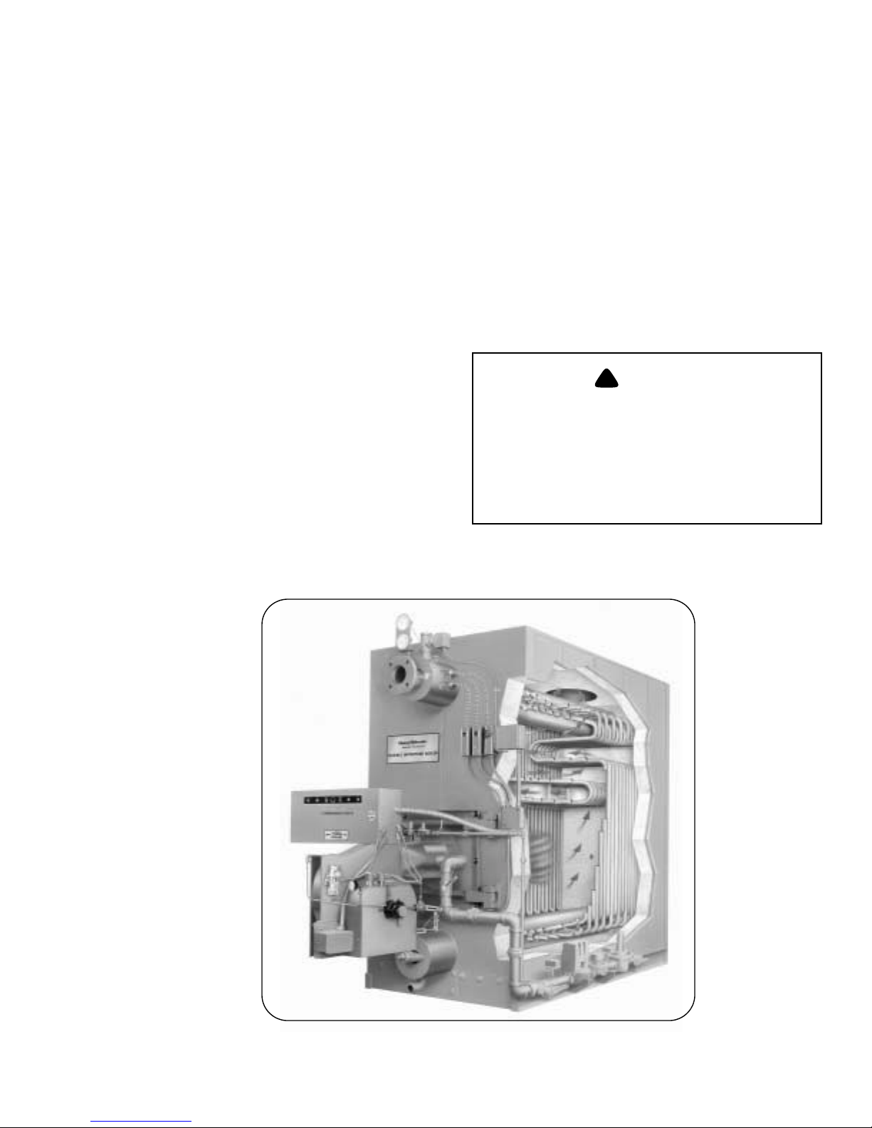
Figure 1-1: FLX Cut Away
Page 10

Chapter 1 GENERAL DESCRIPTION
B. The Boiler
The Cleaver-Brooks Model FLX is a five-pass steel boiler
with flexible watertubes formed and arranged so as to direct
the flow of combustion gases through the boiler. The pressure
vessel conforms to Section I or IV of the ASME code. The
pressure vessel consists of the formed tubes, the external
downcomer, and the top and bottom drums to which they
connect. The heated area of the pressure vessel is contained
within a gas tight insulated casing that is composed of
removable formed steel panels.
Always order genuine Cleaver-Brooks parts from your
local Cleaver-Brooks authorized representative.
The boiler and related equipment installation are to be in
compliance with the standards of the National Board of Fire
Underwriters. Installation should also conform to state and
local codes governing such equipment. Prior to installation,
the proper authorities having jurisdiction are to be consulted,
permits obtained, etc. All boilers in the above series comply,
when equipped with optional equipment, to Industrial Risk
Insurers (IRI), Factory Mutual (FM), or other insuring
underwriters requirements.
The Model FLX boiler is a packaged watertube boiler of
welded steel construction and consists of a pressure vessel,
burner, burner controls, forced draft fan, damper, refractory,
and appropriate boiler trim.
The type of service that your boiler is required to provide has
an important bearing on the amount of waterside care it will
require.
!
CAUTION
DANGER
Waterside care is of prime importance. For
specific information or assistance with your
water treatment requirements, contact your
Cleaver-Brooks service and parts represen
tative. Failure to follow these instructions
could result in equipment damage
Feedwater equipment should be checked and ready for use.
Be sure that all valves, piping, boiler feed pumps, and
receivers are installed in accordance with prevailing codes
and practices.
Water requirements for both steam and hot water boilers are
essential to boiler life and length of service. Constant
attention to water requirements will pay dividends in the form
of longer life, less down-time, and prevention of costly
repairs. Care taken in placing the pressure vessel into initial
service is vital. The waterside of new boilers and new or
remodeled steam or hot water systems may contain oil, grease
or other foreign matter. A method of boiling out the vessel to
remove accumulations is described in Chapter 3.
The operator should be familiar with Chapter 3 before
attempting to place the unit into operation.
-
Hot water is commonly used in heating applications with the
boiler supplying water to the system at 180 °F to 220 °F. The
operating pressure for hot water heating systems usually is
30 psig to 125 psig.
Steam boilers are designed for low and high pressure applications. Low pressure boilers are limited to 15 psig design
pressure, and are typically used for heating applications.
High pressure boilers are limited to 150 psig design pressure,
and are typically used for process steam applications.
Steam and hot water boilers are defined according to design
pressure and operating pressure. Design pressure is the max
imum pressure used in the design of the boiler for the purpose of calculating the minimum permissible thickness or
physical characteristics of the pressure vessel parts of the
boiler. Typically, the safety valves are set at or below design
pressure. Operating pressure is the pressure of the boiler at
which it normally operates. The operating pressure usually is
maintained at a suitable level below the setting of the pres
sure relieving valve(s) to prevent their frequent opening during normal operation.
-
C. Construction
Steam boilers designed for 15 psig and hot water boilers
designed for 250°F at 160 psi or less are constructed in
accordance with Section IV, Heating Boilers, of ASME Code.
Steam boilers designed for 150 psig are constructed in
accordance with Section I, Power Boilers, of the ASME
Code.
D. Steam Controls (All Fuels)
-
1. Operating Limit Pressure Control (Figures 1-2 and 1-3):
Breaks a circuit to stop burner operation on a rise of
boiler pressure at a selected setting. It is adjusted to stop
or start the burner at a preselected pressure setting.
2. High Limit Pressure Control (Figure 1-2 and 1-3):
Breaks a circuit to stop burner operation on a rise of
pressure above a selected setting. It is adjusted to stop the
burner at a preselected pressure above the operating limit
control setting. The high limit pressure control is
equipped with a manual reset.
1-2 750-177
Page 11
GENERAL DESCRIPTION Chapter 1
3. Modulating Limit Pressure Control (Figure 1-2 and 1-3):
Senses changing boiler pressures and transmits the
information to the modulating motor to change the
burner firing rate when the manual-automatic switch is
set on “automatic.”
4. Low Water Cutoff and Pump Control (Figure 1-2, 1-4
and 1-5): Float-operated control responds to the water
level in the boiler. It performs two distinct functions:
•Stops firing of the burner if water level lowers below the
safe operating point. Energizes the low-water light in the
control panel; also causes low-water alarm bell (optional
equipment) to ring. Code requirements of some models
require a manual reset type of low-water cutoff.
•Starts and stops the feedwater pump (if used) to maintain
water at the proper operating level.
!
CAUTION
DANGER
Determine that the main and auxiliary low
water cutoffs and pump control are level af
ter installation and throughout the equipment’s operating life. Failure to follow these
instructions could result in equipment dam
age.
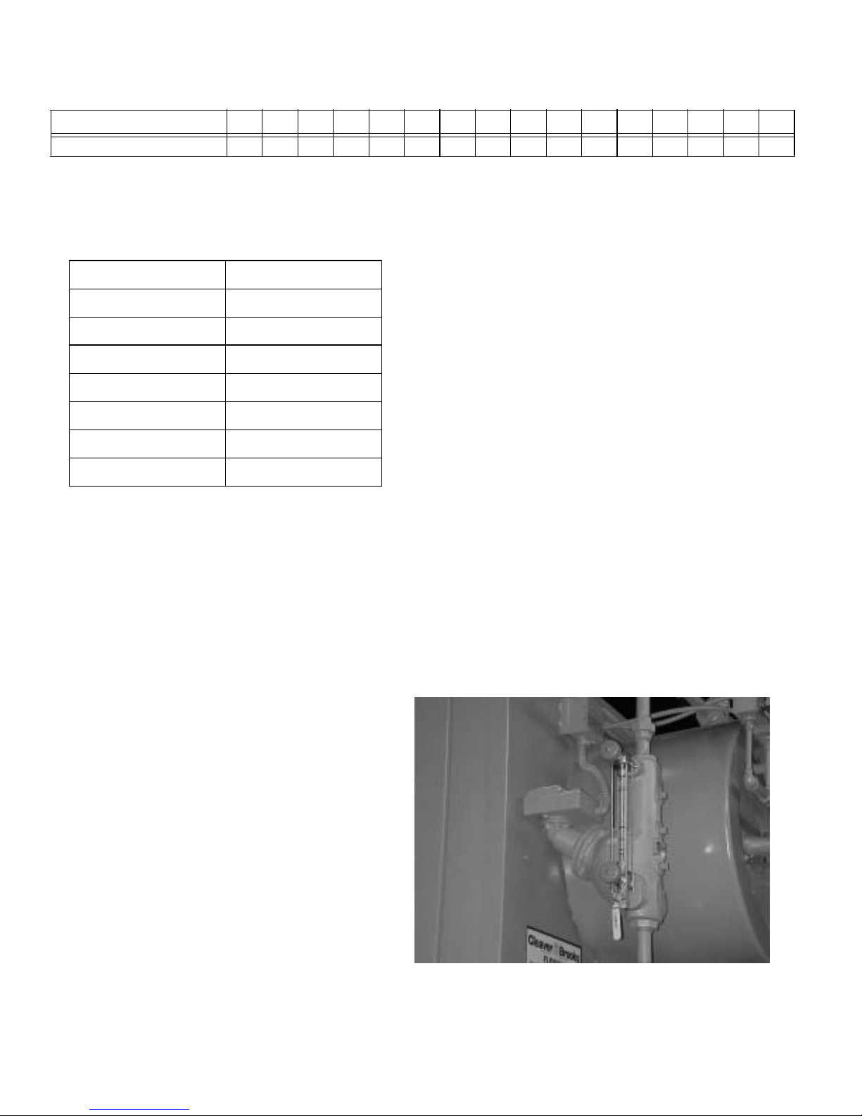
5. Water Column Assembly (Figure 1-2): Houses the lowwater cutoff and pump control and includes the water
gauge glass, gauge glass shutoff cocks.
6. Water Column Drain Valve (Figure 1-2): Provided so
that the water column and its piping can be flushed
regularly to assist in maintaining cross-connecting
piping and in keeping the float bowl clean and free of
sediment. A similar drain valve is furnished with
auxiliary low-water cutoff for the same purpose.
7. Gauge Glass Drain Valve (Figure 1-2): Provided to flush
the gauge glass.
8. Safety Valve(s) (Figure 1-6 and 1-8): Prevent buildup
over the design pressure of the pressure vessel. The size,
rating and number of valves on a boiler is determined by
the ASME Boiler Code. The safety valves and the
discharge piping are to be installed to conform to the
ASME code requirements. The installation of a valve is
of primary importance to its service life. A valve must be
mounted in a vertical position so that discharge piping
and code-required drains can be properly piped to
prevent buildup of back pressure and accumulation of
foreign material around the valve seat area. Apply only a
moderate amount of pipe compound to male threads and
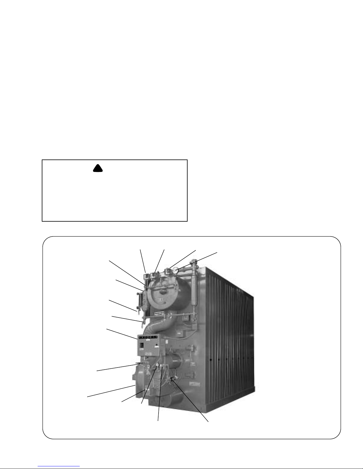
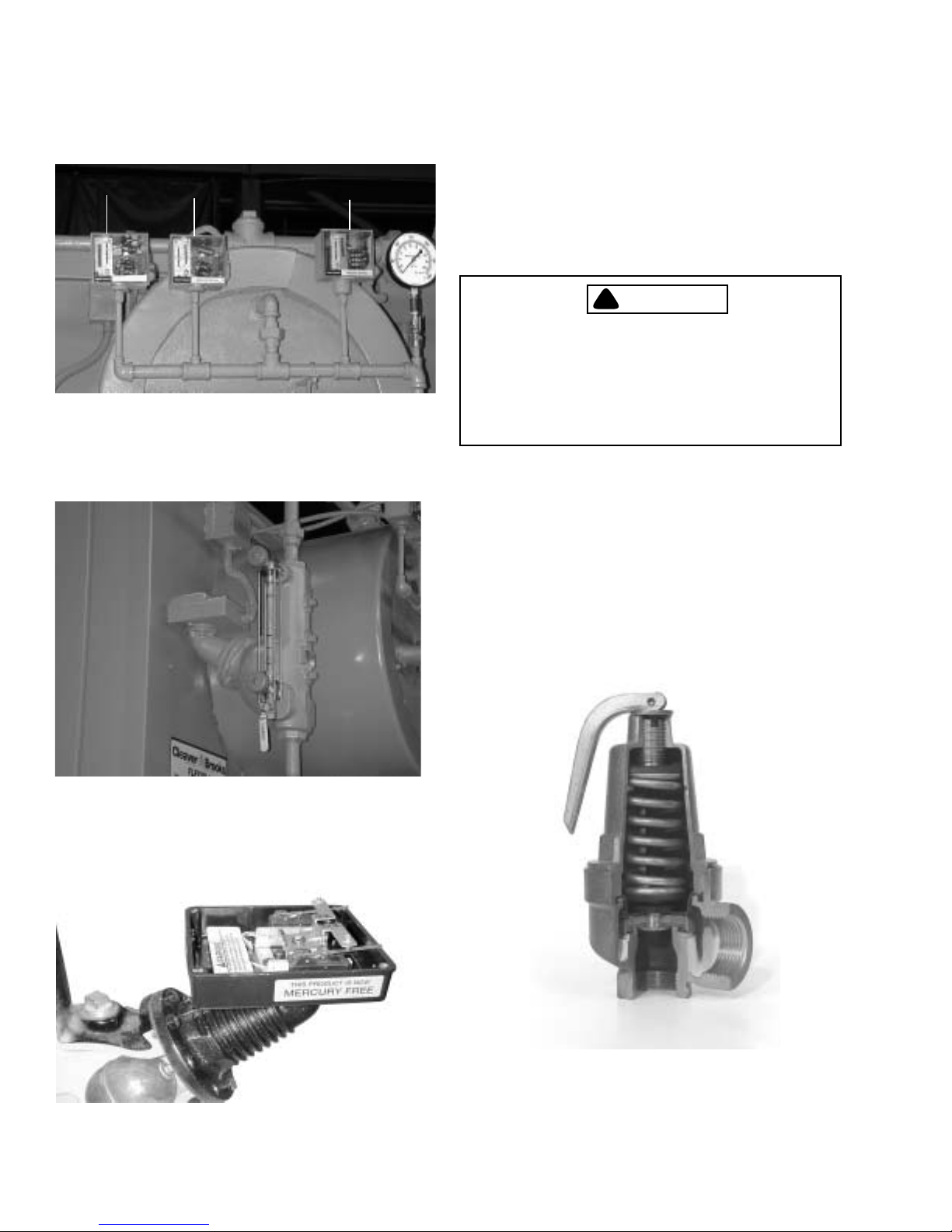
WATER COLUMN
LOW WATER CUTOFF
AND PUMP CONTROL
CONTROL PANEL
FLAME
DETECTOR
FORCED DRAFT
FAN MOT OR
GAUGE GLASS
DRAIN VALVE
WATER COLUMN
DRAIN VALVE
MODULATING
MOTOR
HIGH LIMIT
PRESSURE
OIL SUPPLY
PRESSURE
GAUGE
OPERATING LIMIT
PRESSURE
CONTROL
MODULATING LIMIT
PRESSURE
CONTROLCONTROL
STEAM PRESSURE
GAUGE
750-177 1-3
OIL SOLENOID
VALV ES
OIL PUMP
Figure 1-2: Typical Steam Boiler - Light Oil Fired
Page 12
Chapter 1 GENERAL DESCRIPTION
avoid overtightening, which can distort the seats. Use
only flat-jawed wrenches on the flats provided. When
installing a flange-connected valve, use a new gasket and
12
1. HIGH LIMIT PRESSURE CONTROL
2. OPERATING LIMIT PRESSURE CONTROL
3. MODULATING PRESSURE CONTROL
Figure 1-3: Steam Controls
3
draw the mounting bolts down evenly. Do not install or
remove side outlet valves by using a pipe or wrench in
the outlet.
!
WARNING
DANGER
Only properly certified personnel such as
the safety valve manufacturer’s certified
representative can adjust or repair the
boiler safety valves. Failure to follow these
instructions could result in serious
personal injury or death
E. Hot Water Controls (All Fuels)
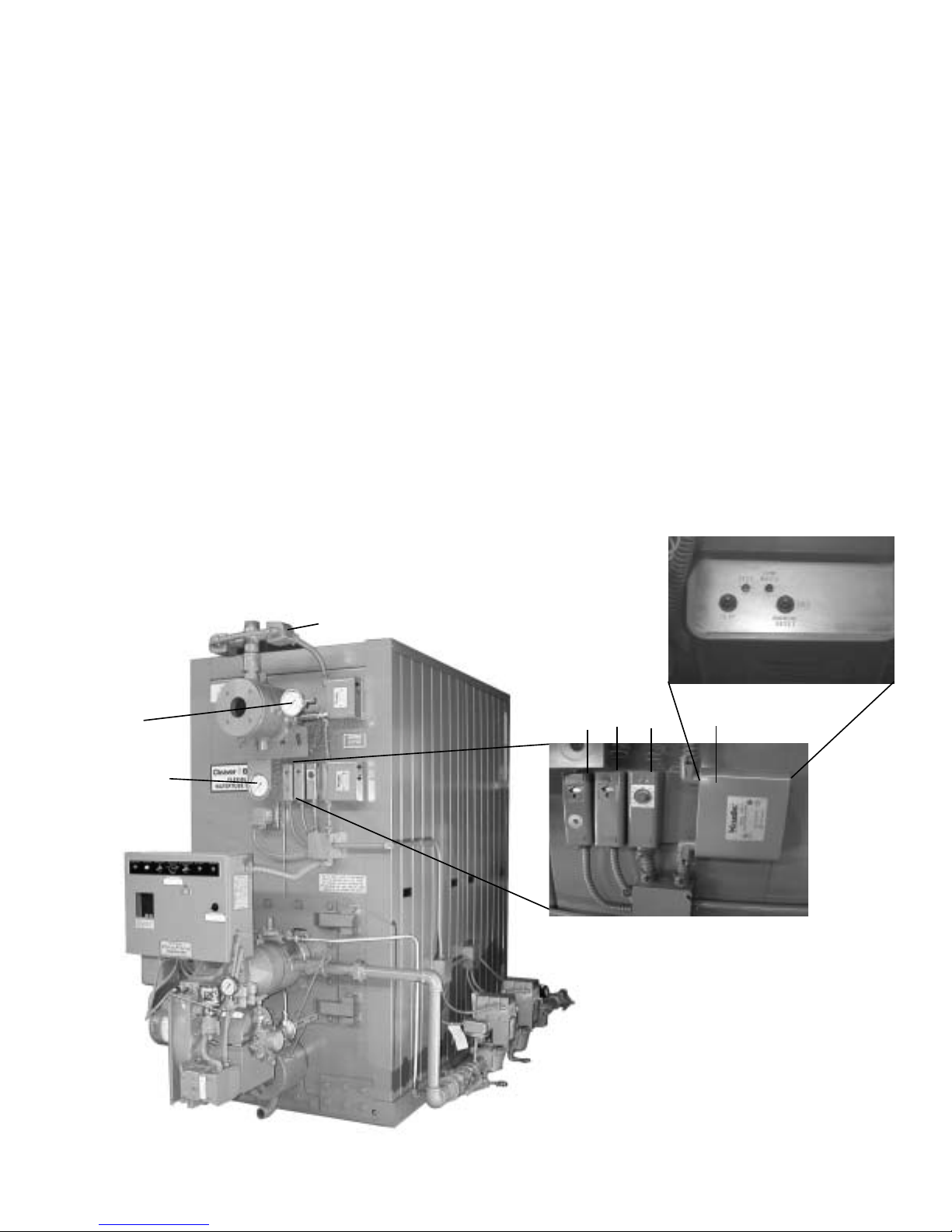
Figure 1-4: Low Water Cut Off (LWCO)
1. Water Temperature Gauge (Figure 1-7): Indicates the
boiler internal water pressure.
2. Water Pressure Gauge (Figure 1-7): Indicates the internal
pressure of the boiler.
3. Operating Limit Temperature Control (Figure 1-7):
Breaks a circuit to stop burner operation on a rise of
boiler temperature at a selected setting. It is adjusted to
Figure 1-5: Low Water Cut Off Pump Control
(Cutaway)
1-4 750-177
Figure 1-6: Safety Valve Cutaway
Page 13
GENERAL DESCRIPTION Chapter 1
stop or start the burner at a preselected operating
temperature.
4. High Limit Temperature Control (Figure 1-7): Breaks a
circuit to stop burner operation on a rise of temperature
at a selected setting. It is adjusted to stop burner at a
preselected temperature above the operating control
setting. The high limit temperature control is equipped
with a manual reset.
5. Modulating Temperature Control (Figure 1-7): Senses
changing boiler water temperature and transmits the
information to the modulating motor to change the
burner firing rate when the manual-automatic switch is
set on “automatic.”
6. Low Water Cutoff (Figure 1-7): Breaks the circuit to stop
burner operation if the water level in the boiler drops
below safe operating point, activating low-water light
and optional alarm bell if burner is so equipped.
7. Auxiliary Low Water Cutoff (Not Shown) (Optional):
Breaks the circuit to stop burner operation if the water
level in the boiler drops below the master low-water
cutoff point.
8. Safety Valve(s) (Figure 1-6 and 1-8): Prevent buildup
over the design pressure of the pressure vessel. The size,
rating and number of valves on a boiler is determined by
the ASME Boiler Code. The safety valves and the
discharge piping are to be installed to conform to the
ASME code requirements. The installation of a valve is
of primary importance to its service life. A valve must be
mounted in a vertical position so that discharge piping
and code-required drains can be properly piped to
prevent buildup of back pressure and accumulation of
foreign material around the valve seat area. Apply only a
moderate amount of pipe compound to male threads and
avoid overtightening, which can distort the seats. Use
only flat-jawed wrenches on the flats provided. When
installing a flange-connected valve, use a new gasket and
draw the mounting bolts down evenly. Do not install or
WATER
PRESSURE
GAUGE
WATER
TEMPERATURE
GAUGE
LOW WATER CUTOFF PROBE
23
1
1. High Limit Temperature Control
2. Operating Limit Temperature Control
3. Modulating Temperature Control
4. Low Water Cutoff Control
4
750-177 1-5
Figure 1-7: Hot Water Controls
Page 14
Chapter 1 GENERAL DESCRIPTION
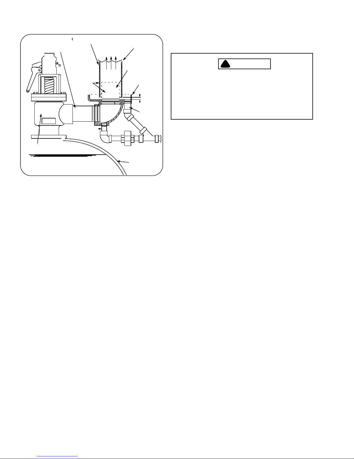
SUPPORT FROM BUILDING
DISCHARGE OPENING
MUST BE EQUAL TO OR LARGER THAN
INLET
SAFETY VALVE
NOTICE: BACK-PRESSURE OF STEAM EXHAUST SYSTEM MUST BE LESS THAN 6% OF SAFETY VALVE SETTING.
WATER LEVEL
CONSTRUCTION
CAUTION - VENT
PIPE
MUST NOT
TOUCH DRIP
PAN EXTENSION
DRIP ELL DRAIN
TO STEAM
VENT
VENT PIPE
DRIP PAN
EXTENSION
AND ELBOW
OPEN DRAIN
TO WASTE
BOILER SHELL
Figure 1-8: Recommended Piping For Steam
Relief Valve (Not furnished by Cleaver-Brooks)
DRIP PAN
1 1/2”
MIN.
DRIP PAN
DRAIN
remove side outlet valves by using a pipe or wrench in
the outlet.
!
WARNING
DANGER
Only properly certified personnel such as
the relief valve manufacturer’s certified
representative can adjust or repair the
boiler relief valves. Failure to follow these
instructions could result in serious
personal injury or death.
1-6 750-177
Page 15

CHAPTER 2
ProFire Burner Operation and Control
A. GENERAL . . . . . . . . . . . . . . . . . . . . . . . . . . . . . . . . 1
B. BURNER. . . . . . . . . . . . . . . . . . . . . . . . . . . . . . . . . . 1
C. RECOMMENDED FUELS AND VENTILATION . 2
D. CONTROLS AND COMPONENTS . . . . . . . . . . . . 2
The burner and all boiler related equipment must be installed
in accordance with applicable local, state or provincial
installation requirements including the National Electrical
Code (NEC) and associated insurance underwriters. Where
applicable, the Canadian Gas Association (CGA) B149 and
Canadian Standards Association (CSA) B140 codes shall
prevail.
Note: If the boiler is not equipped with a
ProFire burner, Please refer to the specific
Operation and Maintenance manual for the
burner supplied.
Note: The main power disconnect for this
equipment must be conspicuously labeled
and placed within
system, and/or equipped with lockout
provisions.
Note: This manual must be readily available
to all operators, and maintained in legible
condition.
sight of the operating
A. GENERAL
The information provided in this manual covers ProFire
burners installed on Flextube boilers.
The information in this chapter provides guidance for startup,
testing, and adjustment of the Cleaver-Brooks ProFire burner.
Personnel working on or operating the burner or related
equipment must become familiar with all the procedures and
information contained in this manual prior to initial startup,
operation and/or adjustment of the burner.
This chapter applies exclusively to the Cleaver-Brooks
ProFire Burner, and focuses specifically on tasks related to
adjustment of linkages and controls for efficient combustion
and safe operation, pre-startup checkout and initial burner
startup.
B. BURNER
The ProFire Burner is designed to operate with natural gas or
light oil at input rates from 1.5 to 12.0 MMBtu/hr. The burner
can be configured to burn natural gas only, oil only, or as a
natural gas or oil burner.
The burner includes all components and controls required for
automatic modulating burner operation, and is also capable of
operation over the full range under manual control.
The model number completely identifies its configuration.
This information is located on the unit parts list, shipped with
the burner. The model number components are as follows:
GP - W - X - Y - Z
Where:
GP designates the burner orientation, blower housing
down.
W designates the fuel; gas, oil, or combination (700, 100,
or 200, respectively).
• 100-Light Oil
• 200- Light Oil and Natural Gas
• 700- Natural Gas
X designates the frame size of the burner (1, 2, 3 & 4).
Y designates burner capacity (MMBtu/hr).
Z designates the insurance underwriter.
For Example:
GP - 700 - 2 - 3.5 - IRI
750-177 2-1
2-1
Page 16
Chapter 2 ProFire Burner Operation and Control
MODEL NO. 150 200 250 300 350 400 450 500 550 600 700 800 900 1000 1100 1200
Gas
15480 20640 25800 30960 36120 41280 46440 51600 56760 61920 72240 82560 92280 103200 113520 123840
(scfh)
Comb
Air
(Dry)
Oil (scfh)
NOTES:
1. Natural gas @ 1000 Btu/cu-ft.
2. No. 2 oil @ 140,000 Btu/gal.
1207 1609 2012 2414 2817 3219 3621 4024 4426 4828 5633 6438 7243 8048 8853 9658
(lb/hr)
17050 22733 28414 34098 39782 45463 51146 56831 62514 68196 79562 90928 102294 113662 125028 136394
1269 1692 2115 2538 2961 3384 3807 4231 4654 5077 5923 6769 7640 8462 9308 10154
(lb/hr)
Table 2-1: Combustion Air Flow Requirements
indicates a blower housing “down” unit that burns only
natural gas; it is made of size-two components, and is rated
D
for 3.5 MMBtu/hr fuel input at high fire and is configured to
meet IRI (Industrial Risk Insurers) standards.
ABC
EFG
C. RECOMMENDED FUELS AND
VENTILATION
ProFire burners are designed to burn either natural gas or
light oil (#2), as defined by ASTM D396 - 1978 specification.
!
WARNING
DANGER
This burner is designed to burn only those
fuels shown on the burner data plate.
Burning fuels not specified on the data plate
could cause damage to the equipment, or
can result in serious personal injury or
death.
Note: Structural enclosures for this
equipment must be configured to allow
ample flow of combustion and ventilation
air. See Table 2-1 for combustion air volume
requirements.
D. CONTROLS AND COMPONENTS
The burner can be equipped with special operating controls,
various types of flame safeguard systems, and/or a system to
minimize NOx emissions. The wiring and dimension
diagrams and construction reference list (available with the
burner) confirm the specific features and equipment included.
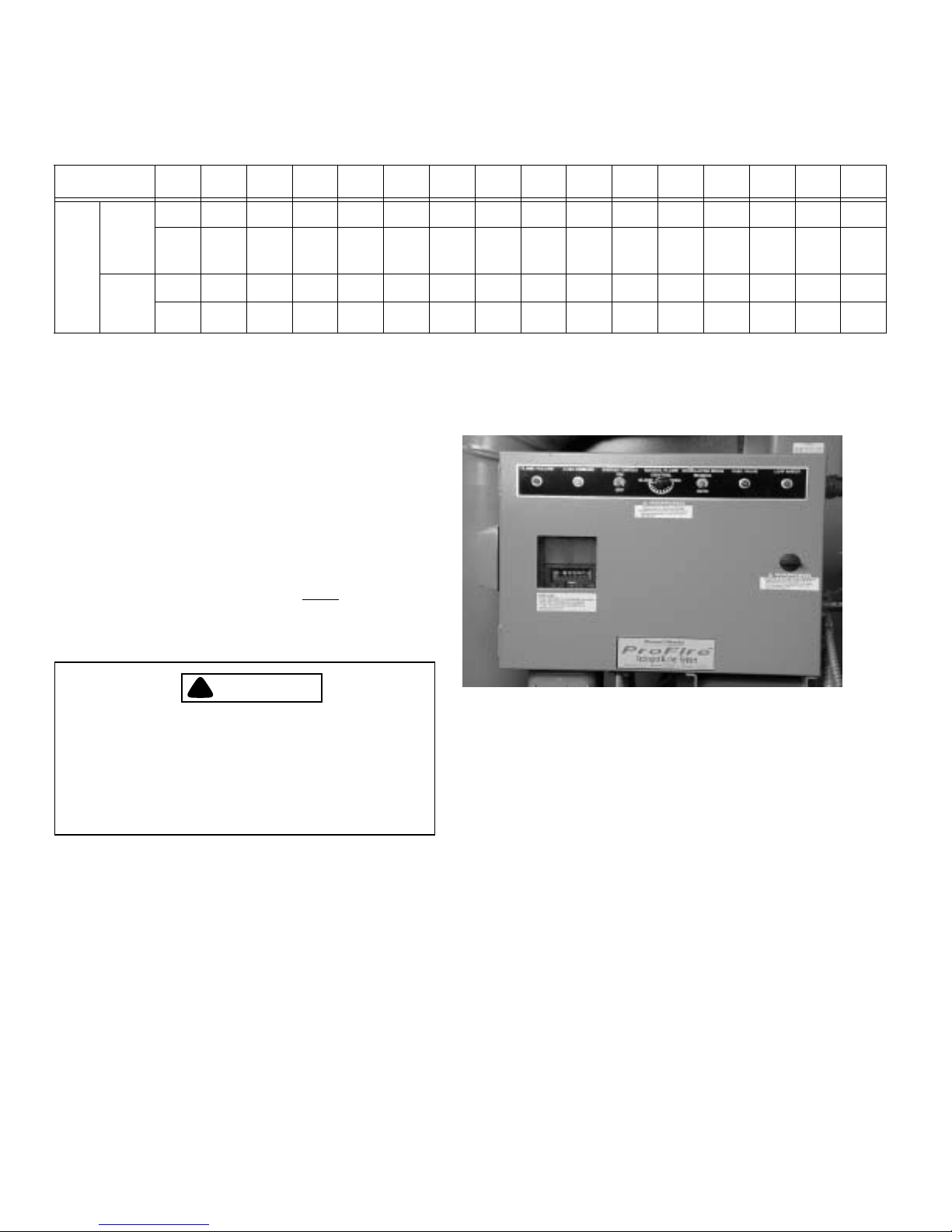
Refer to Figures 2-1 and 2-2 for component locations. The
A. FLAME FAILURE LIGHT
B. LOAD DEMAND LIGHT
C. BURNER SWITCH
D. MANUAL FLAME CONTROL
E. MANUAL-AUTO SWITCH
F. FUEL VALVE LIGHT
G. LOW WATER LIGHT
8
Figure 2-1: Control Cabinet
following list describes components and basic functions of
the burner.
1. Electrical Control Cabinet (Figure 2-1): The control
cabinet houses many of the electrical control
components and the flame safeguard. The operator
control switches and indicator lights are located on the
face of the control cabinet door. The following controls
and indicators are provided:
• Flame Failure Light: Illuminates (red) 20 seconds after the flame is extinguished. When this
happens, the system automatically shuts down;
manual reset of the flame safeguard is required.
2-2 750-177
• Load Demand Light: Illuminates (white) when
Page 17

ProFire Burner Operation and Control Chapter 2
the boiler operating controls indicate a demand
for hot water or steam.
• Burner Switch: Activates or deactivates the operating cycle of the flame safeguard control.
• Manual Flame Control: When in Manual Mode,
it provides manual adjustment of the burner fir
A
-
B
ing rate between low-fire and high-fire operation.
• Manual-Auto Switch: Allows the operator to
override the automatic boiler controls for manual
firing rate adjustment.
• Fuel Valve Light: Illuminates (green) when the
selected fuel valve is energized.
A. FLAME SAFEGUARD
B. FUEL SELECTION SWITCH
• Low Water Light: Illuminates (red) when the
boiler low-water cutoff control is activated.
2. Flame Safeguard (Figure 2-2): The flame safeguard
controls the operating sequences of the combustion
system (prepurge, pilot, firing, and shutdown). The
control also monitors the flame, using a scanner which is
sensitive to specific flame frequencies. The flame
safeguard also automatically shuts down the burner
when the flame signal becomes too weak. Different types
of flame safeguard devices can be installed in the
combustion systems. Check the wiring diagram for your
burner for information on the specific unit installed on
your burner.
3. Fuel Selection Switch (Figure 2-2): Allows the operator
to select either gas or oil as the active fuel on
combination burners. (The switch is located inside the
control cabinet.)
4. Pilot Gas Train (Figure 2-3). The standard pilot gas train
consists of a manual stopcock, a gas pressure regulator,
and a solenoid-operated gas shut-off valve. The gas pilot
valve assembly controls a relatively small flow rate of
natural gas to operate the gas-electric pilot.
5. Blast Tube (Figure 2-3). The blast tube functions as a
duct for combustion air, and houses the fuel nozzle(s),
gas pilot assembly, diffuser, and air baffle assemblies.
Figure 2-2: Control Cabinet (Open)
A
B
F
C
A. PILOT GAS TRAIN
B. BLAST TUBE
C. BLOWER HOUSING
D. COMBUSTION AIR FAN MOTOR
E. IGNITION TRANSFORMER
F. COMBUSTION AIR PROVING SWITCH
Figure 2-3: ProFire Burner (Left Side)
E
D
6. Blower Housing (Figure 2-3). The blower housing
encloses the impeller. The fan drive motor is mounted
directly to the blower housing.
7. Combustion Air Fan Motor (Figure 2-3). The electric
motor drives the combustion air fan and the oil pump (if
so equipped).
8. Ignition Transformer (Figure 2-3). The ignition
transformer produces the high voltage required for spark
generation by the pilot electrode(s).
9. Combustion Air Proving Switch (Figure 2-3). The
combustion air proving switch provides confirmation to
the flame safeguard that the combustion air fan is
750-177 2-3
Figure 2-4: Impeller
Page 18
Chapter 2 ProFire Burner Operation and Control
providing air flow. The fuel supply valves will not open
if this switch does not sense adequate air pressure.
10. Impeller (Figure 2-4). The impeller is designed with
backwards-inclined vanes. It is located inside the blower
housing, and is driven by the combustion air fan motor.
The impeller provides combustion air to the burner
assembly. Removing the impeller requires the use of the
impeller puller, part number 943-388 (Figure 2-8)
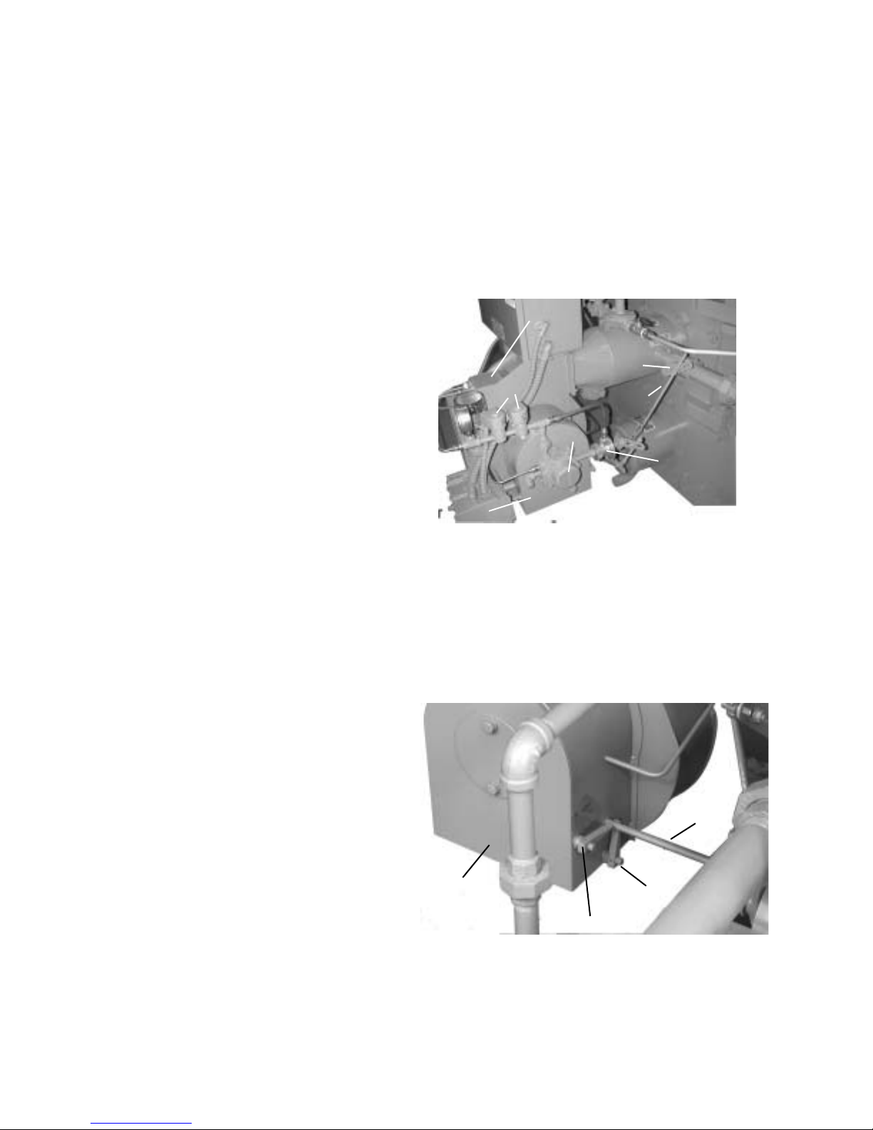
11. Gas Butterfly Valve (Figure 2-5). The gas butterfly valve
regulates the flow rate of natural gas into the burner. The
gas butterfly valve is connected, by linkage and a jack
shaft, to the modulating motor, which provides the rotary
motion to open and close the valve.
12. Valve Linkage (Figure 2-5). The valve linkage transfers
the modulating motion from the main air shutter shaft to
the fuel metering valve shafts. The linkage provides a
means of adjustment to maintain the correct fuel-to-air
ratio over the entire burner operating range, high fire to
low fire.
13. Oil Metering Valve (Figure 2-5). The oil metering valve
regulates the flow rate of oil into the burner. The oil
metering valve is connected by linkage and a jack shaft
to the modulating motor, which provides the rotary
motion to open and close the valve.
14. Oil Pump (Figure 2-5). The oil pump provided for oil
burning is coupled to an extension of the combustion air
fan shaft.
15. Modulating Motor (Figure 2-5). The modulating motor is
coupled to the jack shaft that operates the main air shutter
and the fuel valve linkages. The modulating motor
produces the torque and rotary positioning required for
firing rate control.
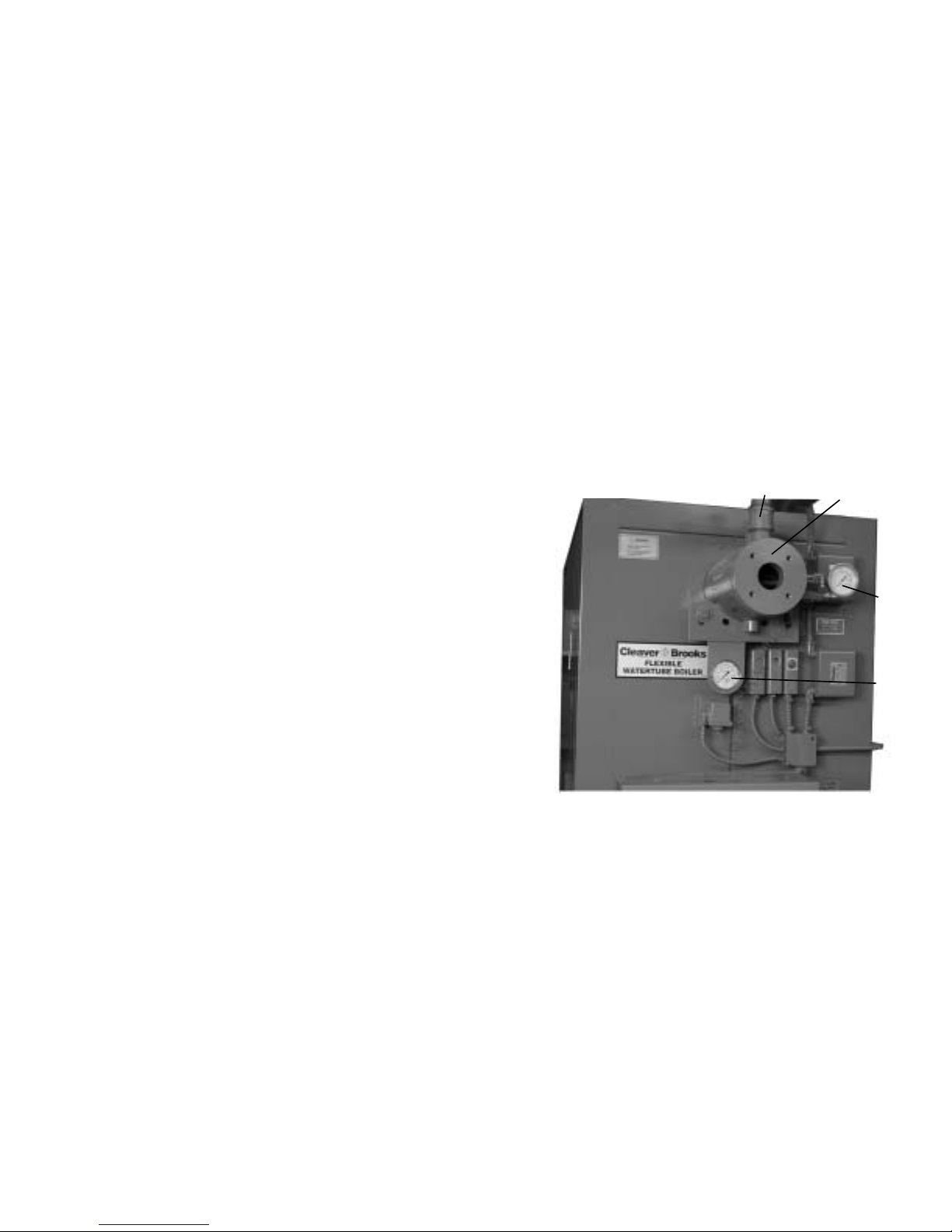
20. Airbox (Figure 2-6). The airbox is attached to the inlet side of
the fan housing. It serves as the inlet and flow regulating
valve for combustion air, and houses the combustion air
control shutters.
21. Main Air Shutter Shaft (Figure 2-6). The main air shutter
modulates the combustion air between low fire and high fire
conditions. The shaft connects the modulating motor to the
main air shutter and to the fuel valve linkage assemblies.
G
A
F
B
D
C
E
A. GAS BUTTERFLY VALVE
B. VALVE LINKAGE
C. OIL METERING VALVE
D. OIL PUMP
E. MODULATING MOTOR
F. OIL SOLENOID VALVES
G. REAR CAP
Figure 2-5: Oil And Gas Piping To Burner
16. Oil Solenoid Valves (Figure 2-5). The oil solenoid
valves are in series and downstream of the oil metering
valve in the supply line to the oil burner assembly. Two
valves are provided. These valves are simultaneously
energized to open and release fuel oil to the burner. The
valves close to stop combustion when oil is the fuel.
17. Rear Cap (Figure 2-5). The rear cap contains the locking
setscrew for adjustment of the diffuser relative to the air
D
baffle, and also the flame scanner for the flame
safeguard. The rear cap must be removed to enable
removal of the oil gun assembly.
C
B
18. Low-Fire Shutter (Figure 2-6). The low-fire shutter
provides a means to set the correct combustion air flow
A
rate for low-fire operation. The handle indicates relative
shutter position.
19. High-Fire Shutter (Figure 2-6). The high-fire shutter
provides a means to set the correct combustion air flow
rate for high-fire operation. The handle indicates relative
A. LOW-FIRE SHUTTER
B. HIGH-FIRE SHUTTER
C. AIRBOX
D. MAIN AIR SHUTTER SHAFT
shutter position.
Figure 2-6: Airbox and Shutters
2-4 750-177
Page 19

ProFire Burner Operation and Control Chapter 2
ITEM
ACCOMPLISHED
BY
REMARKS
Daily
Gauges, Monitors,
Operator Make visual inspection and record readings in log.
and Indicators
Instrument and
Operator Make visual check against recommended specifications.
Equipment Settings
Low-water Fuel Cut-
Operator Refer to instructions.
off And Alarm
Weekly
Low-water Fuel Cut-
Operator Refer to instructions.
off And Alarm
Firing Rate Control Operator Verify factory settings.
Igniter Operator Make visual inspection. Check flame signal strength if meter-fitted (see
“Combustion safety controls”).
Pilot and Main Fuel
Valves
Operator Open limit switch. Make audible and visual check. Check valve position
indicators, and check fuel meters
Flame Failure
Controls
Flame Signal
Strength Controls
Operator Close manual fuel supply for (1) pilot, (2) main fuel cock and/or
valve(s). Check safety shutdown timing. Record in log.
Operator If flame signal meter installed, read and log for both pilot and main
flames. Notify service if readings are very high, very low, or fluctuating.
Refer to instructions.
Monthly
Low Fan Pressure,
Operator Manually adjust until switch opens.
Interlock
High & Low Gas
Operator Refer to instructions. Manually adjust until switch opens.
Pressure Interlocks
High & Low Oil
Operator Refer to instructions. Manually adjust until switch opens.
Pressure Interlocks
Semi- Annually
Low-water Fuel Cutoff And Alarm
Operator Perform a slow drain test in accordance with ASME Boiler and Pres-
sure Vessel Code Section VI.
Firing Rate Control Service Technician Verify factory settings.
Figure 2-7: Recommended Test Schedule
750-177 2-5
Page 20

Chapter 2 ProFire Burner Operation and Control
ITEM
Inspect Burner
ACCOMPLISHED
BY
Service Technician Refer to instructions.
REMARKS
Components
Annually
High Limit Safety
Service Technician Manually adjust until switch opens.
Control
Firing Rate Control Service Technician Check with combustion test.
Pilot and Main Gas
Service Technician Perform leakage tests. Refer to instructions
or Main Oil Fuel
Valves
Operating Control Service Technician Manually adjust until switch opens.
Fuel Valve Interlock
Service Technician Refer to instructions. Disconnect POC wire at valve.
Switch (POC)
Burner Position
Service Technician Refer to instructions. Disconnect wire at valve.
Interlock
Low Fire Start Inter-
Service Technician Refer to instructions.
lock
Automatic Change
Over Control (Dual
Fuel)
Pilot Turndown
Tests
Refractory Hold-In
Controls
High & Low Oil
Pressure Interlocks
Pilot Turndown
Tests
Service Technician Under supervision of gas utility.
Service Technician Required after any adjustments to flame scanner mount or pilot burner.
Verify annually. Refer to instructions.
Service Technician See “Pilot turndown tests.”
As Required
Operator Refer to instructions. Manually adjust until switch opens.
Service Technician Required after any adjustments to flame scanner mount or pilot burner.
Verify annually. Refer to instructions.
Figure 2-7: Recommended Test Schedule (Continued)
2-6 750-177
Page 21

ProFire Burner Operation and Control Chapter 2
Special Tools
The Impeller puller, part number 943-388 should be used to
remove the impeller from the fan motor shaft.
To order special tools, contact your authorized Cleaver-Brooks
representative.
Figure 2-8: Impeller Puller Part Number
943-388
750-177 2-7
Page 22

Chapter 2 ProFire Burner Operation and Control
Notes:
2-8 750-177
Page 23
CHAPTER 3
Pressure Vessel Care
A. General. . . . . . . . . . . . . . . . . . . . . . . . . . . . . . . . . . .3-1
B. Water Requirements (Hot Water Boilers) . . . . . . . .3-1
C. Water Requirements (Steam Boilers . . . . . . . . . . . .3-3
D. Water Treatment . . . . . . . . . . . . . . . . . . . . . . . . . . .3-4
E. Blowdown . . . . . . . . . . . . . . . . . . . . . . . . . . . . . . . .3-4
F. Cleaning . . . . . . . . . . . . . . . . . . . . . . . . . . . . . . . . . .3-6
G. Boilout . . . . . . . . . . . . . . . . . . . . . . . . . . . . . . . . . . .3-6
H. Washing Out . . . . . . . . . . . . . . . . . . . . . . . . . . . . . .3-8
I. Periodic Inspections . . . . . . . . . . . . . . . . . . . . . . . . .3-8
J. Preparation for Extended Layup . . . . . . . . . . . . . . . .3-9
A. GENERAL
This chapter is devoted primarily to the waterside care of the
pressure vessel.
Proper water supply and treatment are essential to boiler life
and length of service. Proper water treatment will pay
dividends in the form of longer life, less downtime, and
prevention of costly repairs.
Hot water boilers require proper circulation. The system must
be operated as intended by its designer in order to avoid the
possibility of thermal shock with severe stress to the pressure
vessel.
B
A
C
C
Although it is of prime importance, the subject of water
supply and treatment cannot adequately be covered in this
manual. For specific information or assistance with your
water treatment requirements, contact your local CleaverBrooks authorized representative.
B. WATER REQUIREMENTS
(HOT WATER BOILERS)
Air Removal
The hot water outlet (Figure 3-1) is located in the top drum of
the boiler. This location reduces the possibility of released air
(which is trapped at the top of the drum) from entering the
system. Any air (or oxygen) that may be released in the boiler
will collect at the top of the upper drum, where it will escape
through the air vent tapping (Figure 3-1). The tapping must be
properly piped to the expansion tank or a stand pipe and air
bleeder to remove gases that collect at the top of the drum.
750-177 3-1
A. HOT WATER OUTLET
B. AIR BLEED TAPPING
C. PRESSURE/TEMPERATURE GAUGES
Figure 3-1: Upper Drum (Hot Water)
Continuous Flow
The system must be piped and the controls arranged so that
there will be water circulation through the boiler under all
operating conditions. Constant circulation through the boiler
eliminates the possibility of stratification within the unit.
Refer to Fig. 3-1 to determine the maximum GPM circulation
rate of boiler water in relation to full boiler output and system
temperature drop.
Page 24
Chapter 3 Pressure Vessel Care
DT = 20°F DT = 40°F DT = 60°F DT = 80°F DT = 100°F
MODEL
NO.
FLX-150 1.14 122.0 0.30 61.1 0.13 41.1 0.08 30.8 0.05 24.4
FLX-200 1.14 162.3 0.30 81.1 0.13 54.1 0.08 40.6 0.05 32.5
FLX-250 1.77 202.8 0.46 101.4 0.21 67.6 0.12 50.7 0.08 40.6
FLX-300 1.85 243.4 0.48 121.7 0.22 81.1 0.12 60.9 0.08 48.7
FLX-350 2.49 284.0 0.65 142.0 0.29 94.7 0.17 71.0 0.11 56.8
FLX-400 1.35 324.5 0.35 162.3 0.16 108.2 0.09 81.1 0.06 64.9
FLX-450 1.71 365.1 0.44 182.6 0.20 121.7 0.11 91.2 0.08 73.0
FLX-500 2.03 405.7 0.54 202.8 0.25 135.2 0.14 101.4 0.09 81.1
FLX-550 2.50 446.3 0.67 223.1 0.31 148.7 0.17 111.5 0.11 89.2
FLX-600 2.99 486.8 0.77 243.4 0.35 162.3 0.20 121.7 0.13 97.4
FLX-700 1.75 567.9 0.45 284.0 0.21 189.3 0.12 142.0 0.08 113.6
FLX-800 2.27 649.1 0.59 324.5 0.27 216.4 0.15 162.3 0.10 129.8
FLX-900 2.85 730.2 0.74 365.1 0.33 243.4 0.19 182.6 0.12 146.0
DP
(PSIG)
GPM DP (PSIG) GPM DP (PSIG) GPM DP (PSIG) GPM DP (PSIG) GPM
FLX-1000 4.08 811.4 1.02 405.6 0.42 270.4 0.25 202.8 0.15 163.6
FLX-1100 4.42 892.6 1.15 446.2 0.48 297.4 0.28 223.0 0.18 178.4
FLX-1200 6.20 973.6 1.60 486.8 0.59 324.6 0.31 243.4 0.22 194.8
Table 3-1:Maximum Flow Rates for Hot Water Boilers
System Pressure
!
CAUTION
DANGER
In order to avoid damage to the equipment,
a circulating pump should be interlocked
with the burner so that the burner cannot
operate unless the circulating pump is run
ning.
It is recommended that the system circulating pumps be kept
running, even though the heat users do not require hot water.
The relief device or bypass valve will allow continuous
circulation through the boiler and will help prevent rapid
replacement of boiler water with “cold” zone water.
!
CAUTION
DANGER
The operator should determine that a circulation of water exists through the boiler before initial firing or when firing after the unit
has been drained and refilled. A reduced cir
culation of water or no water circulation
through the boiler when the burner is oper
ating may result in damage to the equipment.
-
-
-
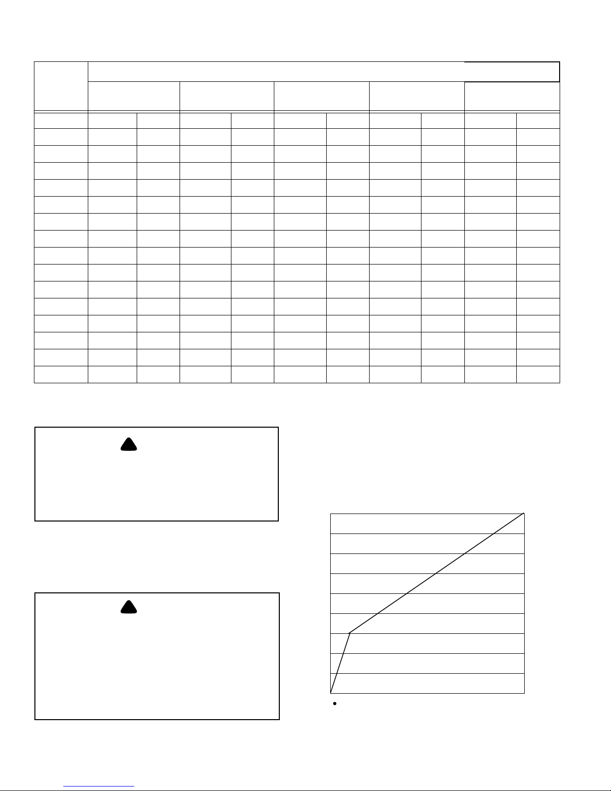
The design of the system and the usage requirements often
will dictate the pressure exerted upon the boiler. Some
systems are pressurized with nitrogen. Caution must be
240
F
230
°
220
210
200
190
180
170
SUPPLY WATER TEMPERATURE -
160
150
10 12 14
16 18 20 22 24
SYSTEM PRESSURE - PSI
26
28
30
Figure 3-2: Minimum System Operating Pressure
3-2 750-177
Page 25
Pressure Vessel Care Chapter 3
exercised to make sure that the proper relationship of pressure
to temperature exists within the boiler so that all of its internal
surfaces are fully wetted at all times. It is for this reason that
the internal boiler pressure, as indicated on the water pressure
gauge, must be held to the level shown in Figure 3-3.
It is advisable to install a thermometer in the return line to
indicate return water temperature. With the return water
temperature and the supply water temperature to the system
known, the temperature differential will be established.
Knowing the flow rate, the operator easily can detect any
excessive load condition and take appropriate corrective
action.
Pressure Drop
There will be a pressure drop of less than 4 psi through all
standardly equipped Cleaver-Brooks boilers operating in any
system that has more than the 20°F temperature drop. This
drop will vary with boiler size and circulation rate. For
specific information, refer to table 3-1, Minimum Flow Rates
for Hot Water Boilers.
Minimum Boiler Outlet Water Temperature
The minimum recommended operating boiler outlet water
temperature is 150°F. When water temperatures lower than
150°F are used, the combustion gases are reduced in
temperature to a point where the water vapor in the gases
condenses. A result of condensation is that fireside corrosion
occurs in the boiler and breeching. The condensation problem
is more severe on a unit that operates intermittently or is
oversized for the actual load. This is not a matter that can be
controlled by boiler design, since an efficient boiler extracts
all the possible heat from the combustion gases.
Multiple Boiler Installations
When multiple boilers of equal or unequal size are installed,
care must be taken to ensure proportional flow through the
boilers. Proportional flow can best be accomplished by use of
balancing cocks and gauges in the supply line from each
boiler. If balancing cocks or orifice plates are used, a
significant pressure drop (for example, 3-5 psi) must be taken
across the balancing device to accomplish proportional flow.
Variations in water temperature and firing rates will result if
care is not taken to ensure proportional flow through the
boilers. In extreme cases, differences in firing rates could
result in a net header water temperature below the desired
temperature.
C. WATER REQUIREMENTS
(STEAM BOILERS)
Deaeration
The most important factor in the life of a steam pressure
vessel is the proper conditioning of the boiler feed water.
Corrosive gasses, such as oxygen and carbon dioxide, must
be removed from the feed water in order to prevent
degradation of the pressure vessel. For this reason CleaverBrooks recommends the use of a deaeration system as an
integral part of a complete boiler installation. If
circumstances do not allow the implementation of a
deaeration system, then serious consideration should be given
to effective alternatives such as a feed water preheater
combined with a chemical oxygen scavenger. Complete
boiler water chemistry parameters are given in Table 3-3.
Note: In order to maintain a minimum outlet
water temperature of 150°F the low limit of
the Operating Temperature Control should
be set at least 10° higher.
If the operating water temperature going to the system must
be lower than 150°F, the operating boiler outlet water
temperature should still be held to a minimum of 150°F.
Mixing valves are used to reduce the supply temperature
going to the system.
Note: The minimum return water
temperature through the boiler is 120°F.
!
CAUTION
DANGER
Three-way valves and system controls
should be installed or set so that the boiler
cannot be bypassed. A reduced circulation
of water or no water circulation through the
boiler when the burner is operating may re
sult in damage to the equipment.
750-177 3-3
-
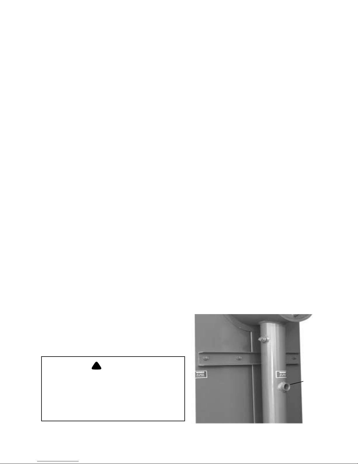
Feed Water Supply
The internal dynamics of the Model FLX steam boilers
require the capability to deliver large quantities of feed water
to the boiler on demand. (Feed water inlet Figure 3-3.)
Sudden changes in firing rate or operating pressure of the
FEED WATER
SUPPLY PORT
Figure 3-3: Feed Water Inlet
Steam Boiler
Page 26
Chapter 3 Pressure Vessel Care
BOILER MODEL 150 200 250 300 350 400 450 500 550 600 700 800 900 1000 11 00 1200
Minimum Feed Rate (gpm) 4.9 6.6 8.2 9.9 11.6 13.2 14.9 16.5 18.2 19.8 23.1 26.4 29.7 33.0 36.3 39.6
Note: Feedwater to the boiler must be at least 60 °F, for minimum performance, 212 °F is preferred.
Table 3-2: Minimum Boiler Feed Water Flow Rates (Steam Boiler)
Because of the variables involved, no one “boiler compound”
Silica 150 ppm
Specific Conductance 3500 µmho/cm
Total Alkalinity 300 ppm as C
Total Hardness 0 ppm as CaCO
aCO3
3
Oxygen (O2)7 ppb
can be considered a “cure-all”; nor is it advisable to
experiment with homemade treating methods. A sound
treatment program should include a periodic analysis of the
water in the system.
The internal or waterside surfaces of the pressure vessel
should be inspected at sufficient intervals to detect the
presence of any corrosion, pitting, contamination, or
accumulations of foreign matter. If any of these conditions
pH 10
are detected, contact your local Cleaver-Brooks authorized
Representative for advice on corrective action. It is
Total Iron 0.05 ppm
Oily Matter 1 ppm
Table 3-3: Boiler Water Quality Limits
(Steam Boilers)
recommended that a properly sized water meter be installed
in the raw water makeup line to accurately determine the
amount of raw water admitted to the boiler. It is a false
assumption that a hot water boiler does not require water
treatment. Even though a hot water unit generally operates on
a closed system and blowdown seldom is practiced, the need
boiler will initiate a “call for water” from the make-up
controller, which will require that the feed water be delivered
to the boiler in sufficient quantities to prevent a low water
remains to be alert to system water losses. Knowing the
amount of makeup water admitted to the system will aid in
maintaining proper waterside conditions.
cutoff trip. Table 3-2 lists the minimum feed water flow
requirements for the various boiler models. In addition, feed
water must be warmed to a minimum of 60°F. in order to
ensure reliable operation of the boiler. The feed water supply
should be adjusted to deliver water to the boiler at or above
these minimum rates.
A steam boiler requires periodic blowdown of the boiler and
water column (Figure 3-4). Blowdown is the removal of some
of the concentrated water from the boiler and the water level
E. BLOWDOWN
D. WATER TREATMENT
Properly treated boiler water will result in maximum
effectiveness and long trouble-free life of the pressure vessel.
Contact your local Cleaver-Brooks Representative or water
management consultant for complete information on how to
prevent damage resulting from inadequate water treatment.
The objectives of water treatment in general are to:
1. Prevent hard scale and soft sludge deposits that inhibit
heat transfer and that could lead to overheated metal and
costly downtime and repairs.
2. Eliminate corrosive gases in the supply or boiler water.
To accomplish these objectives, the boiler requires proper
water treatment before and after introduction of water into the
unit. The selection of pretreatment processes depends upon
the water source, its chemical characteristics, the amount of
makeup water needed, system operation practices, etc.
3-4 750-177
Figure 3-4: Low Water Cutoff and Gauge Glass with
Blowdown Valve
Page 27
Pressure Vessel Care Chapter 3
control system, in order to lower the concentration of solids
in the water.
Solids are introduced to the boiler with the feedwater, even
though this water may be treated prior to use. These solids
become less soluble when the water is heated and evaporated,
and tend to accumulate on heating surfaces.
Periodic blowdown and chemical treatment are necessary to
prevent concentration of solids in the boiler water, and
attachment of these solids to waterside heating surfaces
(scaling).
Scale has a low heat transfer value and acts as an insulating
barrier on heating surfaces. A buildup of scale will result in
lower operating efficiency and, consequently, higher fuel
consumption. More importantly, scale buildup can result in
overheating of boiler metal. This can result in tube failures or
other pressure vessel damage.
!
CAUTION
DANGER
Boiler and water level control blowdown
must be performed on a regular basis to en
sure that concentrated solids are removed
from the boiler and in order to avoid damage
to the equipment.
Water column and gauge glass blowdown valves are located
on the water column assembly. The boiler blowdown
tapping(s) can be found at the bottom of the lower drum.
Most blowdown lines are provided with two valves. These
are generally a quick-opening valve nearest the boiler and a
slow-opening globe-type valve downstream. Valves will vary
depending upon pressure involved and the make or
manufacturer.
-
When initially opening the blowdown valve,
open the valve slowly to heat the discharge
piping. Failure to follow this procedure
could result in rapid expansion and damage
to the piping.
The drop of the water level in the gauge glass can be used in
determining the length of time that the blowdown valve is left
open. This is to be used as a reference only, as proper water
analysis on a regular basis will serve as an indicator of the
effectiveness of the blowdown procedures used.
Do not pump the lever action valve open
and closed when draining water during
blowdown. The hydraulic forces resulting
from this pumping action could break the
valve bodies or pipe fittings in the blow
down lines.
Blowdown valves should be closed in a specific order after
draining water for blowdown. Close the downstream (slow
opening) valve first, followed by the quick-opening valve
next to the boiler. Open the downstream valve slightly to
release the water trapped between the valves, then close the
valve again.
The water column and gauge glass should be blown down by
draining until the water in the gauge glass is clear. Open and
close the water column and gauge glass blowdown valves
slowly, allowing the water in the gauge glass to rise to a
normal level before repeating the process.
!
CAUTION
DANGER
!
CAUTION
DANGER
-
Blowdown Procedure
Blowdown is most effective when the boiler water is hot and
the burner is being fired at the lowest rate. This ensures that
the water in the boiler is being circulated, and that the solids
in the water are in suspension.
!
WARNING
DANGER
Be sure that the blowdown piping is in good
condition, the discharge vents are clear of
obstruction, and that the waste is piped to a
safe point of discharge, in order to avoid
serious personal injury or death.
If a quick-opening valve and globe-type or slow-opening
valve are installed, the quick-opening valve is normally
opened first and closed last. Control of the water released
from the boiler is accomplished with the slow-opening valve.
750-177 3-5
Under no circumstances should a blowdown valve be left
open and unattended during the blowdown operation.
Frequency of Blowdown
In practice, the boiler blowdown valve(s) should be opened
periodically in accordance with a set operating schedule.
Frequency and duration of the blowdown are to be
determined by chemical analysis of boiler water and
waterside boiler condition, as observed during regular
inspections.
From an economy standpoint, frequent short blowdown is
preferred to irregularly scheduled, lengthy blowdown. This is
particularly true when the suspended solids content of the
water is high.
Page 28
Chapter 3 Pressure Vessel Care
F. CLEANING
Although it may be necessary to clean the system,
information in this chapter deals primarily with cleaning the
boiler under isolated conditions.
System piping connected to the boiler may contain oil,
grease, or other foreign matter. These impurities must be
removed to prevent damage to the heating surfaces of the
pressure vessel. Chemical cleaning generally is necessary in
this case and the entire system should be drained after
cleaning. Consult your local Cleaver-Brooks authorized
representative for recommended cleaning compounds and
application procedures. For information on Boilout, see
Section G, in this chapter.
Pressure Vessel
Cleaning of the waterside of the pressure vessel should be
done during the course of initial installation. The waterside of
the pressure vessel must be cleansed of grease, sludge, and
foreign material. Such deposits will shorten the life of the
pressure vessel and interfere with the efficient operation and
function of control or safety devices. In addition, deposits
might cause unnecessary and expensive rework, repairs, and
downtime.
The pressure vessel and the hot water system represent in
effect, a closed system. Although individual components of
the system may already have been cleaned, it is possible that:
G. BOILOUT
Any oil, grease, or other contamination found to be present on
waterside heating surfaces should be removed promptly by
boiling out the unit with an alkaline detergent solution.
Note: Before boiling out, the burner must be
ready for firing. Refer to the burner manual
for details. The operator must be familiar
with the boilout procedures outlined in this
section.
Cleaver-Brooks recommends the use of CB3900,(P/N 797-
1797) an alkaline, detergent-based product suitable for
cleaning all internal surfaces in heating and process boilers.
Contact your local Cleaver-Brooks authorized representative
for additional information or assistance.
If the system is to be cleaned with the boiler, consider the
additional water content of the system in determining the
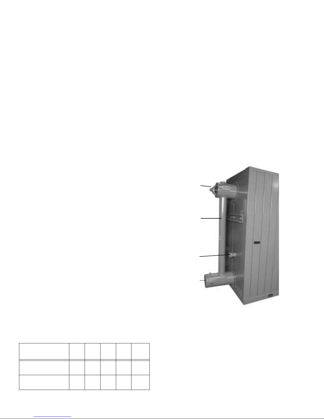
UPPER HAND HOLE
1. The cleaning was not adequate.
2. An old system was partially or totally involved.
DOWNCOMER
3. Conditions may have prevented an adequate cleaning of
the piping.
Therefore, it is recommended that the entire system be
cleaned, after installation of all components is completed.
SIGHT
PORT
The pressure vessel waterside should be inspected on a
periodic basis. An inspection will reveal the true internal
conditions and will serve as a check against conditions
indicated by chemical analysis of the boiler water. An
SYSTEM
INLET
inspection should be performed 3 months after the initial start
up, then at regular 6, 9, or 12 month intervals thereafter. The
frequency of periodic inspections will depend upon the
internal conditions found, the particular installation, and the
operating conditions that the boiler is subjected to.
Figure 3-5: Rear Panel (Hot Water Boiler
If any deterioration or unusual conditions are observed,
contact your local Cleaver-Brooks authorized Representative
for recommendations.
150-
300-
400-
700-
Boiler Size
Water Capacity (US
gal.) Hot Water
Water Capacity (US
gal.) Steam - Flooded
3-6 750-177
Table 3-4: Water Capacity
250
350
91 106 174 228 269
194 215 293 464 562
600
900
1000-
1200
amount of chemical required. The water capacity of CleaverBrooks FLX Boilers is listed in Table 3-4.
Boilout Procedure
1. Prepare the boiler for firing by taking the standard
precautions. Check for any situations that might present
a hazard.
2. Remove upper and lower drum handhole covers and
inspect all internal waterside surfaces. Remove debris
Page 29
Pressure Vessel Care Chapter 3
and wash all internal surfaces, including tubes. It may be
necessary to use a high pressure hose or a wash out lance
to flush out inaccessible areas. Reinstall the lower drum
handhole cover. (Use standard service gaskets during the
boilout procedure.)
3. The relief valve(s) must be removed before adding the
boilout solution so that neither the solution nor the
contaminants that it may carry can come in contact with
the valve(s). Use care in removing, handling, and
reinstalling these valves.
Note: For relief valve installation
information, refer to Chapter 8, Section E.
“Controls.”
4. Replace the regular gauge glass with a temporary gauge
glass that can be discarded after the cleaning (steam
boilers).
5. An overflow pipe should be connected to one of the top
boiler openings and routed to a safe point of discharge. A
relief valve tapping is usually used for this purpose. The
overflow connection to the boiler should incorporate a
tee fitting for adding cleaning solution to the boiler.
6. Fill the unit with clean water to a point just below the
access port in the upper drum. It is important that the
water used for the filling process is at a temperature of
70°F or above.
12. Throughout the entire process, each blow-down point or
valve should be blown at least once every two hours. The
total amount of water blown from all points each time
should be approximately one-half gauge glass, this
amount being equally divided among the various manual
blowdown points and continuous blowdown system.
Blow the surface and/or continuous blow-down points
first, followed by the other blowdown points lower on
the boiler. After each blowdown cycle, the water level
should be brought back to full. If the total alkalinity in
the cleaning solution falls to a level below 3000 ppm, it
may be necessary to add additional Cleaver-Brooks
3900, using a chemical pump.
13. Allow a small amount of fresh water to enter the boiler in
order to create a slight overflow that will carry off
surface impurities. Continue to boil and overflow until
the water clears.
14. It is difficult to provide specific recommendations
regarding the duration of the cleaning process. In
general, a period of 18 to 36 hours will prove sufficient
to internally clean the water-side of the boiler. The
condition of the water blown from the boiler is the best
indicator as to whether the cleaning process is complete.
15. Discontinue firing, and allow the water to cool. After
letting the water cool to 120°F or less, drain the boiler.
7. Add the recommended amount of Cleaver-Brooks 3900,
using a chemical pump. Never pump the cleaning
chemical into the boiler before adding water.
!
WARNING
DANGER
The chemicals used in this procedure are
corrosive to eyes and skin. Always refer to
the Material Safety Data Sheet to ensure that
the proper safety equipment and
precautions are present. Failure to heed this
warning could result in serious personal
injury or death.
8. Reinstall the upper handhole cover.
9. Continue to fill the boiler until it is full (indicated by flow
from the overflow connection).
10. Recheck the burner, gauge glass, pressure gauge,
feedwater supply and the position of all valves. Make
sure that all water feeding and level indicating apparatus
are in proper working condition.
11. Fire the boiler intermittently at the burners lowest fire
rate until the water reaches the boiling point. The water
should be held at this temperature for at least five hours.
Note: Do not produce pressure in the boiler.
!
WARNING
DANGER
Be sure to drain the hot water to a safe point
of discharge to avoid the possibility of
scalding, serious personal injury or death.
16. Remove the drum handhole cover, and wash the
waterside surfaces thoroughly, using a high pressure
water stream. Direct the water stream into each
individual tube. If possible, this washing should be done
from the bottom up. A wash out lance is available from
your local Cleaver-Brooks authorized representative.
17. Inspect the waterside surfaces. If they are not clean,
repeat the boilout procedures.
18. Replace the handhole covers (using new gaskets) and
reinstall the relief valve(s).
Note: Refer to Chapter 8, Section E,
“Controls” for information regarding proper
installation of relief valves.
19. If the boiler is to be put into service immediately, fill the
boiler with clean, treated water and fire the burner until
the water has been heated to at least 180°F to drive off
any dissolved gases that might otherwise corrode the
metal.
20. If the boiler is not to be put into immediate service, refer
to the section on boiler layup procedures in this chapter.
750-177 3-7
Page 30
Chapter 3 Pressure Vessel Care
H. WASHING OUT
Depending on system integrity, feedwater quality, or
operating conditions, the water side of the boiler may need to
be washed out on occasion.
In theory, a hot water system and boiler that have been
initially cleaned, filled with clean, treated water, and with no
makeup water added, will require no further cleaning or
treatment. However, minor system leaks may allow the
admission of additional water or air into the boiler.
Introduction of raw (untreated) makeup water or air to a hot
water boiler may lead to pitting, corrosion, or formation of
sludge, sediment, or scale on the pressure vessel waterside.
The waterside condition of steam boilers can be likewise
affected by feedwater quality, load demands, operating
conditions, or blowdown practices.
The waterside of a hot water or steam boiler should be
cleaned and inspected no later than three months after the
boiler is put into service. Subsequent cleaning of waterside
surfaces should be performed as indicated through periodic
inspection.
In order to thoroughly wash out the waterside of the pressure
vessel, the handhole covers at the ends of the upper and lower
drums must be removed. The interior surfaces of the drums
should be washed with a high pressure hose. Tubes should be
cleaned by directing a high pressure stream of water into the
end of each tube, first from the bottom, and then from the top
drum.
Note: A washout lance for this purpose is
available from your local Cleaver- Brooks
authorized representative.
available. Be prepared to perform any testing required by the
inspector, including a hydrostatic test.
When shutting down a boiler, the load should be reduced
gradually and the pressure vessel should be cooled at a rate
that avoids a temperature differential that can cause harmful
stresses. Normally, all pressure should be relieved before a
vessel is drained in order to prevent uneven contraction and
temperature differential that can cause tubes to leak. Draining
the unit too quickly may cause the baking of deposits that
may be present on the heating surfaces.
Note: Check to see that system valves,
feedwater valves, all fuel valves, expansion
tank, and electrical switches are shut off
prior to opening the handholes or the
burner access door. After proper cooling
and draining of the vessel, flush out the
waterside with a high pressure water
stream. Remove any scale or deposits from
the waterside surfaces and check for
internal or external corrosion or leakage.
Fireside surfaces also should be cleaned so that metal
surfaces, welds, joints, tube fittings, and any previous repairs
can be readily checked.
!
WARNING
DANGER
To avoid the hazard of electrical shock,
which could cause serious personal injury
or death, the use of a low voltage flashlight
is recommended during an internal
inspection.
Control and water column connections on steam boilers
should be checked for accumulated deposits, and cleaned as
required.
After waterside cleaning has been completed, replace the
handhole covers, using new gaskets.
Note: Handhole cover gaskets are installed
dry; that is, without application of a sealing
compound.
I. PERIODIC INSPECTION
Insurance regulations or local codes and good maintenance
will require that the pressure vessel be inspected periodically
by an authorized inspector. Sufficient notice is generally
required to allow removal of the boiler from service and
preparation for inspection. An internal inspection may be
required before cleaning or flushing.
Have the following information available for the inspector:
boiler design, dimensions, generating capacity, operating
pressure and temperature, time in service, defects found
previously, and any repairs or modifications made to the unit.
Reference records of previous inspections also should be
3-8 750-177
Fireside Inspection
Access for inspection of the firing chamber, or furnace, is
gained through the hinged burner door. Inspection of the
upper pass requires removal of the side casing panels and
second and fourth pass cover plates. Refer to Chapter 8,
Section C, “Fireside Cleaning,” for information regarding
outer and inner casing removal.
Fireside tube surfaces should be checked for corrosion or
accumulation of soot. Use a vacuum cleaner and wire brush
to remove light corrosion or soot.
Localized, heavy corrosion on fireside tube surfaces may
indicate a leaking tube or ferrule connection. If a tube or tube
ferrule leak is indicated, the source of the leakage must be
found and repaired before putting the boiler back in service.
A leak from a tube-to-drum connection may require removal
and reseating of the tube. A heavily corroded or leaking tube
must be replaced in order to assure continued reliable
operation of the boiler. Information regarding tube
replacement can be obtained from your local Cleaver-Brooks
authorized representative.
Page 31

Pressure Vessel Care Chapter 3
Waterside Inspection
Check all water piping and valves for leaks, wear, corrosion,
and other damage. Replace or repair the piping and valves as
necessary. Inspection covers at one end of the upper and
lower drums provide access to the interior of the drums for
visual inspection or washout. The interior surfaces of the
drums should be examined for any sign of corrosion or
accumulation of deposits.
J. PREPARATION FOR EXTENDED
LAYUP
Many boilers used for heating or seasonal loads or for
standby service may have extended periods of non-use. The
procedures outlined in this section are designed to allow a
boiler to be kept off line for any period of time without
damage to the unit. Special care must be taken so that neither
waterside nor fireside surfaces are allowed to deteriorate
from corrosion. Operating boilers can be protected from
corrosion and scale by applying various chemical treatments
and monitoring the system on a regular basis. However,
boilers that are taken off line, even for short intervals, are
susceptible to oxygen attack. Boiler drums and/or tubes may
sustain pitting type damage during either wet or dry layup if
proper precautions are not taken.
Preparing The Boiler For Layup
To prepare a boiler for layup, thoroughly clean the fireside by
removing any soot or other products of combustion from the
tubes, exposed drum surfaces, and refractory.
!
CAUTION
DANGER
The insulating refractory covering the top of
the bottom drum must be protected from
damage when work is being done in the
boiler furnace area. Damage to the insula
tion may eventually cause damage to the
boiler itself.
Generally, a good brushing will clean fireside surfaces. Use a
wire brush for metal surfaces and a soft bristle brush for the
refractory. Sweep away or vacuum any accumulation.
To prevent condensation from forming in the control cabinet,
keep the control circuit energized. For extended layup
periods, especially where high humidity or large swings in
ambient temperature occur, the flame safeguard control
should be removed and stored in a dry atmosphere.
It is recommended that the burner air inlet be blocked to
prevent the flow of warm, moist air through the boiler.
-
Oxygen solubility at ambient (off-line) temperatures can be
many times that of normal boiler operating temperatures. The
higher the oxygen concentration, the greater the oxygen
corrosion potential. Problems also can occur as a result of
improper shutdown procedures, where settled solids can dry
in a hard, adherent deposit.
Care must be take to prevent fireside corrosion, especially
when firing oil that contains sulfur. Dormant periods, and
even frequent shutdowns, expose the fireside surfaces to
condensation during cooling. Moisture and any sulfur residue
can form an acid solution. Under certain conditions, and
especially in areas with high humidity, the corrosive effect of
the acid can be serious. An acid solution could eat through or
severely damage boiler tubes or other metal heating surfaces
during the time that a boiler is out of service.
Too many conditions exist to lay down definite rules for
individual installations. In general, there are two methods of
storage: wet or dry. Your local Cleaver-Brooks authorized
representative can recommend the better method based on the
circumstances of your particular installation. Regardless of
the method employed, the boiler should be thoroughly
cleaned and inspected prior to storage. With either method,
common sense dictates a periodic recheck of fireside and
waterside conditions during layup to meet the requirements
of special or job site conditions.
!
CAUTION
DANGER
A label should be affixed to the burner advising that the air inlet has been blocked.
Failure to remove the air inlet block when at
tempting to operate the burner may result in
damage to the equipment.
-
Dry Storage
Dry storage generally is used for boilers that are to be out of
service for some time or for boilers that might be subjected to
freezing conditions. With the dry storage method, the boiler
must be thoroughly dried because any moisture would cause
corrosion. Drying can be accomplished by the use of a small
stove or heater.
Both fireside and waterside surfaces must be cleaned of all
scale, deposits, soot, and other combustion products as soon
as possible after shutdown.
All openings to the pressure vessel, such as handholes or
inspection ports, should be closed tightly. Feedwater and
system valves should be closed. Dampers should be closed to
prevent air from reaching the fireside surfaces.
Steps must be taken to eliminate moisture by placing
moisture-absorbing materials on trays inside the boiler. Two
moisture-absorbing materials are: quick-lime (at 2 pounds for
3 cubic feet of volume) or silica gel (at 5 pounds for 30 cubic
feet of volume). As soon as the material is in place, close all
boiler openings and blank all connections.
750-177 3-9
Page 32

Chapter 3 Pressure Vessel Care
possibility of freezing temperatures must be considered.
!
WARNING
DANGER
Materials described in this section may be
considered hazardous under the U.S.
Occupational Safety and Health Act of 1970.
Material Safety Data Sheets should be
obtained and understood prior to the use of
these products to avoid the possibility of
serious personal injury or death.
Wet Storage
Note: It is always best to consult with a
water treatment consultant before
proceeding with extended layup.
Wet storage is used when the boiler will be out of service for
shorter periods of time, when a boiler is held in standby
conditions, or in cases where dry storage is not practical. The
boiler held in wet storage can be brought back into service
more quickly than one held in dry storage. However, the
Again, take care to protect metal surfaces. Because of the
number of variables, it is difficult to offer definite
recommendations. However, it is suggested that the pressure
vessel be drained, thoroughly cleaned internally, and refilled
to overflowing with treated water.
If deaerated water is not available, the unit should be fired to
boil the water for a short period of time in order to drive off
oxygen in the water.
Tightly close all connections and apply a small positive
pressure to compensate for the vacuum that will develop as
the unit cools to room temperature. Internal water pressure
should be maintained at greater than atmospheric pressure.
Nitrogen often is used to pressurize the vessel.
The boiler water should be tested weekly as long as the unit
is in storage. Additional chemicals may be required to
prevent internal corrosion. If more chemicals are added, it is
desirable to circulate the boiler water for a short time by
means of an external pump.
Contact your local Cleaver-Brooks authorized representative
for water treatment chemicals or assistance.
Notes
3-10 750-177
Page 33

CHAPTER 4
Sequence Of Operation
A. General . . . . . . . . . . . . . . . . . . . . . . . . . . . . . . . . . .4-1
B. Circuit And Interlock Controls . . . . . . . . . . . . . . . . 4-1
C. Sequence Of Operation - Oil Or Gas. . . . . . . . . . . . 4-2
D. Flame Loss Sequence . . . . . . . . . . . . . . . . . . . . . . . 4-3
A. GENERAL
Chapter 4 outlines the electrical sequencing of various
controls through the pre-purge, ignition, run, and shutdown
cycles of the burner.
The program relay establishes the sequence of operation and
directs the operation of all other controls and components to
provide an overall operating sequence.
Note: The make or model of the program
relay provided will vary depending upon job
specifications. The following sequence
applies regardless of the make or model.
Please refer to the Wiring Diagram (WD)
prepared by Cleaver-Brooks for your
specific installation.
Abbreviations for the various electrical components are listed
in Figure 4-1. The sequences outlined in Chapter 4 employ
specific nomenclature to aid in applying the text to the wiring
diagram.
The burner and control system are in starting condition when
the following conditions exist:
• Boiler water is up to the correct level, closing the lowwater cutoff switch.
• The low-water light (panel) is off.
• The operating limit pressure control (steam boiler) or the
operating limit temperature control (hot water boiler) and
high limit pressure or temperature control are below their
cutoff setting.
• All applicable limits are correct for burner operation.
• The load demand light glows.
All entrance switches are closed and power is present at the
line terminals of:
• Blower motor starter
• Oil pump motor starter (if provided).
The sequences do not attempt to correlate the action of the
fuel supply system or feedwater system except for the
interlock controls that directly relate to the action of the
program relay. Chapters 5 and 6 contain operating
instructions and specific information on setting and adjusting
the controls.
B. CIRCUIT AND INTERLOCK
CONTROLS
The burner control circuit is a two-wire system designed for
115 Vac, 60 Hz, single-phase power.
The electrical portion of the boiler is made up of individual
circuits with controls that are wired in a manner designed to
provide a safe workable system. The program relay provides
connection points for the interconnection of the various
circuits.
The controls used vary depending upon the fuel oil or gas and
the specific requirement of applicable regulatory bodies.
Refer to the boiler wiring diagram to determine the actual
controls provided. The circuits and controls normally used in
the circuits follow and are referred to in the following
sequence of operation.
Limit Circuit:
• Burner switch (BS)
• Operating limit control (OLC) - pressure or temperature
• High limit control (HLC) - pressure or temperature
• Low-water cutoff (LWCO)
• Gas-oil selector switch (GOS) - (Combination burner
only)
• Low gas pressures switch (LGPS)
• High gas pressure switch (HGPS)
Fuel valve interlock circuit
• Main gas valve auxiliary switch (MGVAS)
• Oil valve auxiliary switch (OVAS)
750-177 4-1
Page 34

Chapter 4 Sequence Of Operation
Blower Motor Starter Circuit
• Blower motor starter (BMS)
Running lnterlock Circuit
• Blower motor starter interlock (BMSI)
• Combustion air proving switch (CAPS)
Low Fire Proving Circuit
• Low fire switch (LFS)
Pilot Ignition Circuit
• Gas pilot valve (GPV)
• Ignition transformer (IT)
• Gas pilot vent valve (GPVV) (if provided)
Flame Detector Circuit
• Flame detector (FD)
• Main fuel valve circuit
• Main gas valve (MGV)
• Main gas vent valve (MGVV) (if provided)
• Oil valve (OV)
• Main fuel valve light (FVL)
Firing Rate Circuit
• Damper motor transformer (DMT)
• Modulating damper motor (MDM)
• Manual-automatic switch (MAS)
• Manual flame control (MFC)
• Modulating control (MC)
To comply with requirements of insurance underwriters such
as Factory Mutual (FM), Industrial Risk Insurers (IRI) or
others, additional interlock devices may be used in addition to
the circuits mentioned in Section B.
High Fire Proving Circuit
• High fire switch (HFS)
C. SEQUENCE OF OPERATION - OIL
OR GAS
On a combination fuel unit, the gas/oil switch must be set for
the proper fuel.
The following sequence occurs with power present at the
program relay (PR) input terminals and with all other
operating conditions satisfied.
Pre-Purge Cycle - When the burner switch (BS) is turned
“on,” and controls wired in the “limit” and “fuel valve
interlock” circuits are closed and no flame signal is present,
the “blower motor start circuit” is powered energizing the
blower motor starter (BMS). The load demand light (LDL)
turns on.
At the same time, the program relay signals the modulating
damper motor (MDM) to open the air damper. The damper
begins to open and drives to its full open or high fire position.
Opening the damper motor allows a flow of purging air
through the boiler prior to the ignition cycle.
On certain boilers the circuitry will include a high fire switch
(HFS). The purpose of the switch is to prove that the
modulating damper motor (MDM) has driven the damper to
the open position during the pre-purge cycle. In this instance,
the “high fire proving circuit” is utilized.
The controls wired into the “running interlock circuit” must
be closed within 10 seconds after the start sequence. In the
event any of the controls are not closed at this time, or if they
subsequently open, the program relay will go into a safety
shutdown.
At the completion of the high fire purge period, the program
relay signals the modulating damper motor (MDM) to drive
the air damper to its low fire position.
To assure that the system is in low fire position prior to
ignition, the low fire switch (LFS) must be closed to complete
the “low fire proving circuit.” The sequence will stop and
hold until the modulating damper motor (MDM) has returned
to the low fire position and the contacts of the low fire switch
(LFS) are closed. Once the low fire switch is closed, the
sequence is allowed to continue.
Note: The ignition trial cannot be started if
flame or a flame simulating condition is
sensed during the pre-purge period. A
safety shutdown will occur if flame is
sensed at this time.
Running Interlock and Limit Circuit
• Low oil pressure switch (LOPS)
• High oil pressure switch (HOPS)
• Auxiliary low-water cutoff (ALWCO)
4-2 750-177
Ignition Cycle - The ignition transformer (IT) and gas pilot
valve (GPV) are energized from the appropriate pilot ignition
terminal.
Note: An oil-fired burner may be equipped
with a direct spark rather than a gas pilot.
The ignition sequence of both is identical.
Page 35

Sequence Of Operation Chapter 4
The pilot flame must be established and proven by the flame
detector (FD) within a 10 second period in order for the
ignition cycle to continue. If for any reason this does not
happen, the system will shut down and safety lockout will
occur.
Note: Depending upon the requirements of
the regulatory body, insurer or fuel being
burned, either the 10 or 15 second pilot
ignition terminal may be used. Both provide
the same function but differ in time interval
allowed for proving main flame ignition.
Refer to the boiler wiring diagram.
With a proven pilot, the main fuel valve(s) (OV or MGV) is
energized and the main fuel valve light (FVL) in the panel is
lighted. The main flame is ignited and the trial period for
proving the main flame begins. It lasts 10 seconds for light oil
and natural gas. At the end of the proving period, if the flame
detector still detects main flame, the ignition transformer and
pilot valve are deenergized and pilot flame is extinguished.
Note: If the main flame does not light, or
stay lit, the fuel valve will close. The safety
switch will trip to lock out the control. Refer
to flame loss sequence (section D) for
description of action.
the pressure vessel metal and refractory to
undesirable conditions.
The burner starting cycle is now complete. The (LDL) and
(FVL) lights on the panel remain lit. Demand firing continues
as required by load conditions.
Burner Shudown-Post Purge - The burner will fire until
steam pressure or water temperature in excess of demand is
generated. With modulated firing, the modulating damper
motor (MDM) should return to the low fire position before
the operating limit control (OLC) opens. When the limit
control circuit is opened, the following sequence occurs:
The main fuel valve circuit is deenergized, causing the main
fuel valve (MGV) or (OV) to close. The flame is
extinguished. The control panel lights (LDL) and (FVL) are
turned off. The blower motor continues to run to force air
through the boiler for the post purge period.
The blower motor start circuit is deenergized at the end of the
post purge cycle and the shutdown cycle is complete.
The program relay is now ready for subsequent recycling, and
when steam pressure or water temperature drops to close the
contacts of the operating control, the burner again goes
through its normal starting and operating cycle.
!
WARNING
DANGER
The cause for loss of flame or any other
unusual condition should be investigated
and corrected before attempting to restart.
Failure to follow these instructions could
result in serious personal injury or death
Run Cycle - With main flame established, the program relay
releases the modulating damper motor (MDM) from its low
fire position to control by either the manual flame control
(MFC) or the modulating control (MC), depending upon the
position of the manual-automatic switch (MAS). This allows
operation in ranges above low fire.
With the manual-automatic switch (MAS) set at automatic,
subsequent modulated firing will be at the command of the
modulating control (MC), which governs the position of the
modulating damper motor (MDM). The air damper and fuel
valves are actuated by the motor through a linkage and cam
assembly to provide modulated firing rates.
Note: Normal operation of the burner should
be with the manual-automatic switch in the
automatic position and under the direction
of the modulating control. The manual
position is provided for initial adjustment of
the burner over the entire firing range. When
a shutdown occurs while operating in the
manual position at other than low fire, the
damper will not be in a closed position, thus
allowing more air than desired to flow
through the boiler. Excess air flow subjects
D. FLAME LOSS SEQUENCE
The program relay will recycle automatically each time the
operating control closes, or after a power failure. It will
lockout following a safety shutdown caused by failure to
ignite the pilot, or the main flame, or by loss of flame.
Lockout will also occur if flame or flame simulating
condition occurs during the prepurge period.
The control will prevent start-up or ignition if limit circuit
controls or fuel valve interlocks are open. The control will
lock out upon any abnormal condition affecting air
supervisory controls wired in the running interlock circuit.
!
CAUTION
DANGER
The lockout switch must be manually reset
following a safety shutdown. The cause for
loss of flame or any unusual condition
should be investigated and corrected before attempting to restart. Failure to follow
these instructions could cause damage to
the equipment.
1. No pilot flame.
The pilot flame must be ignited and proven within a 10second period after the ignition cycle begins. If not proven
within this period, the main fuel valve circuit will not be
powered and the fuel valve(s) will not be energized. The
ignition circuit is immediately deenergized and the pilot
valve closes, the reset switch lights and lockout occurs
immediately.
750-177 4-3
Page 36

Chapter 4 Sequence Of Operation
The blower motor will continue to operate. The flame failure
light and the alarm bell (optional) are energized 10 seconds
later.
The blower motor will be deenergized. The lockout switch
must be manually reset before operation can be resumed.
(Refer to the previous caution.)
2. Pilot but no main flame.
When the pilot flame is proven, the main fuel valve circuit is
energized. Depending upon the length of the trial-for-ignition
period, the pilot flame will be extinguished 10 or 15 seconds
later. The flame detecting circuit will respond to deenergize
the main fuel valve circuit within 2 to 4 seconds to stop the
flow of fuel. The reset switch lights and lockout occurs
immediately. The blower motor will continue to operate.
The flame failure light and alarm bell (optional) are energized
10 seconds later.
The blower motor will be then deenergized. The lockout
switch must be manually reset before operation can be
resumed. (Refer to the previous caution.)
3. Loss of flame.
If a flame outage occurs during normal operation and/or the
flame is no longer sensed by the detector, the flame relay will
trip within 2 to 4 seconds to deenergize the fuel valve circuit
and shut off the fuel flow. The reset switch lights and lockout
occurs immediately. The blower motor continues operation.
The flame failure light and alarm bell (optional) are energized
10 seconds later.
Preventive maintenance and scheduled inspection of all
components should be followed. Periodic checking of the
relay is recommended to see that a safety lockout will occur
under conditions of failure to ignite either pilot or main flame,
or from loss of flame.
The blower motor will be deenergized. The lockout switch
must be manually reset before operation can be resumed.
(Refer to the previous caution.)
If the burner will not start, or upon a safety lockout, the
trouble shooting section in the operating manual and the
technical bulletin should be referred to for assistance in
pinpointing problems that may not be readily apparent.
The program relay has the capability to self-diagnose and to
display a code or message that indicates the failure condition.
Refer to the control bulletin for specifics and suggested
remedies. Familiarity with the program relay and other
controls in the system can be obtained by studying the
contents of the manual and this bulletin.
Knowledge of the system and its controls will make
troubleshooting much easier. Costly down time or delays can
be prevented by systematic checks of the actual operation
against the normal sequence to determine the stage at which
performance deviates from normal. Following a routine may
possibly eliminate overlooking an obvious condition, often
one that is relatively simple to correct.
Remember, a safety device, for the most part, is doing its job
when it shuts down or refuses to operate. Never
attempt to
circumvent any of the safety features.
4-4 750-177
Page 37

Sequence Of Operation Chapter 4
MNEMONIC DESCRIPTION
A
A Amber (Color Of Pilot Light)
AAFL Atomizing Air Failure Light
AAFR Atomizing Air Failure Relay
AAPL Atomizing Air Proven Light
AAPS Atomizing Air Proving Switch
AAPS-B Atomizing Air Proving Switch- Burner
AAPS-C Atomizing Air Proving Switch- Compressor
AASS Atomizing Air Selector Switch
AB Alarm Bell
ACCR Air Compressor Control Relay
ACM Air Compressor Motor
ACMCB Air Compressor Motor Circuit Breaker
ACMF Air Compressor Motor Fuses
ACMS Air Compressor Motor Starter
ACMSI Air Compressor Motor Starter Interlock
AH Alarm Horn
ALFR Assured Low Fire Relay
ALWCO Auxiliary Low Water Cutoff
AM Ammeter
AMS Atomizing Media Switch
AOV Auxiliary Oil Valve
APR Air Purge Relay
APV Air Purge Valve
AR Alarm Relay
AS Auxiliary Switch (Suffix)
ASR Alarm Silencing Relay
ASS Alarm Silencing Switch
ASV Atomizing Steam Valve
AT Annunciator Transformer
AWCBDS Auxiliary Water Column Blowdown Switch
B
B Blue (Color of Pilot Light)
BC Bias Control
BDCS Breeching Damper Closed Switch
BDOS Breeching Damper Open Switch
BDRS Blowdown/Reset Switch
BFPL Boiler Feed Pump Light
BFPM Boiler Feed Pump Motor
BFPMCB Boiler Feed Pump Motor Circuit Breaker
BFPMF Boiler Feed Pump Motor Fuses
BFPMS Boiler Feed Pump Motor Starter
BFPS Boiler Feed Pump Switch
BFTS Back Flow Temperature Switch
BHS Boiler - Header Switch
BIOL Boiler in Operation Light
BIOR Boiler In Operation Relay
BM Blower Motor
BMCB Blower Motor Circuit Breaker
BMCR Blower Motor Control Relay
BMF Blower Motor Fuses
BMPR Blower Motor Power Relay
BMPS Blower Motor Purge Switch
BMR Blower Motor Relay
BMS Blower Motor Starter
BMSI Blower Motor Starter Interlock
BMSS Boiler Master Selector Switch
Figure 4-1: Electrical Nomenclature
MNEMONIC DESCRIPTION
BS Burner Switch
BSS Boiler Selector Switch
BWPM Booster Water Pump Motor
BWT Booster Water Thermostat
C
CAFL Combustion Air Failure Light
CAFR Combustion Air Failure Relay
CAP Capacitor
CAPS Combustion Air Proving Switch
CCCB Control Circuit - Circuit Breaker
CCF Control Circuit Fuse
CCRS Control Circuit Reset Switch
CCT Control Circuit Transformer
CIPL Changeover In Progress Light
CL Canopy Light
CLS Canopy Light Switch
COPS Changeover Pressure Switch
COR Changeover Relay
COTD Changeover Time Delay
CPOL Control Power on Light
CR Control Relay
CSSS Control System Selector Switch
CWPM Circulating Water Pump Motor
CWPMCB Circulating Water Pump Motor Circuit Breaker
CWPMF Circulating Water Pump Motor Fuses
CWPMS Circulating Water Pump Motor Starter
CWPMSI Circulating Water Pump Motor Starter Interlock
CWPR Circulating Water Pump Relay
CWPS Circulating Water Pump Switch
CWSV Cooling Water Solenoid Valve
D
D Denotes Digester Gas Equipment (Prefix)
DCVM Direct Current Voltmeter
DG Draft Gauge
DGHPV Digester Gas Housing Purge Valve
DHWC Deaerator High Water Control
DHWL Deaerator High Water Light
DHWR Deaerator High Water Relay
DISC Disconnect (Entrance Switch)
DLWC Deaerator Low Water Control
DLWL Deaerator Low Water Light
DLWR Deaerator Low Water Relay
DM Damper Motor
DMT Damper Motor Transformer
DNS Day-Night Switch
DODE Delay On Deenergization (Timer)
DOE Delay On Energization (Timer)
DPS Damper Positioning Switch
DS Door Switch
E
EDS Emergency Door Switch
ESS Emergency Stop Switch
ETM Elapsed Time Meter
F
FADM Fresh Air Damper Motor
FADR Fresh Air Damper Relay
FD Flame Detector
750-177 4-5
Page 38

Chapter 4 Sequence Of Operation
MNEMONIC DESCRIPTION
FDJB Flame Detector Junction Box
FDPS Flow Differential Pressure Switch
FFA Flame Failure Alarm
FFL Flame Failure Light
FFR Flame Failure Relay
FGR Flue Gas Recirculation
FGRCDTD Flue Gas Recirculation Cool Down Time Delay
FGRCPS Flue Gas Recirculation Cam Position Switch
FGRFM Flue Gas Recirculation Fan Motor
FGRFMS Flue Gas Recirculation Fan Motor Starter
FGRFMSI Flue Gas Recirculation Fan Motor Starter Interlock
FGRMVLS Flue Gas Recirculation Manual Valve Limit Switch
FGRTD Flue Gas Recirculation Time Delay
FORS First Out Reset Switch
FPM Feed Pump Motor
FPMS Feed Pump Motor Starter
FPR Feed Pump Relay
FPS Feed Pump Switch
FRI Firing Rate Interface
FRP Firing Rate Potentiometer (O2 Trim)
FS Flow Switch
FSS Fuel Selector Switch
FSSM Flame Signal Strength Meter
FVEL Fuel Valve Energized Light
FVL Fuel Valve Light
FVR Fuel Valve Relay
FWC Feed Water Control
FWVT Feed Water Valve Transformer
G
G Green (Color Of Pilot Light)
GGL Gauge Glass Light
GOL Gas Operation Light
GOR Gas-Oil Relay
GOS Gas-Oil Switch
GOR Gas-Oil Relay
GPS Gas Pressure Sensor
GPV Gas Pilot Valve
GPVV Gas Pilot Vent Valve
GR Gas Relay
GSSV Gas Sensor Solenoid Valve
GVEL Gas Valve Energized Light
GVTS Gas Valve Test Switch
H
HATC High Ambient Temperature Control
HBWTC High Boiler Water Temperature Control
HBWTL High Boiler Water Temperature Light
HFAV High Fire Air Valve
HFGV High Fire Gas Valve
HFL High Fire Light
HFOV High Fire Oil Valve
HFPS High Furnace Pressure Switch
HFS High Fire Switch
HFS-A High Fire Switch - Air
HGPL High Gas Pressure Light
HGPR High Gas Pressure Relay
HGPS High Gas Pressure Switch
HHFL Header High Fire Light
MNEMONIC DESCRIPTION
H/LWA High Low Water Alarm
HLC High Limit Control
HLFC High-Low Fire Control
HLPC High Limit Pressure Control
HLTC High Limit Temperature Control
HMC Header Modulating Control
HOPL High Oil Pressure Light
HOPR High Oil Pressure Relay
HOPS High Oil Pressure Switch
HOLC Header Operating Limit Control
HOTL High Oil Temperature Light
HOTR High Oil Temperature Relay
HOTS High Oil Temperature Switch
HPCO High Pressure Cutoff
HSPC High Steam Pressure Control
HSPL High Steam Pressure Light
HSPR High Steam Pressure Relay
HSTC High Stack Temperature Control
HSTL High Stack Temperature Light
HSTS High Stack Temperature Switch
HWAR High Water Alarm Relay
HWC High Water Control
HWCO High Water Cutoff
HWL High Water Light
I
(I.C.) Instantaneously Closed
(I.O.) Instantaneously Open
IL Ignition Light
INT Interval (Timer)
IR Ignition Relay
IT Ignition Transformer
J
JPP Jackshaft Position Potentiometer
L
LAMPS Low Atomizing Media Pressure Switch
LASPS Low Atomizing Steam Pressure Switch
LDL Load Demand Light
LDPS Low Differential Pressure Switch
LDS Low Draft Switch
LFAV Low Fire Air Valve
LFGV Low Fire Gas Valve
LFHTD Low Fire Hold Time Delay
LFL Low Fire Light
LFOV Low Fire Oil Valve
LFPS Low Fire Pressure Switch
LFR Low Fire Relay
LFS Low Fire Switch
LFS-A Low Fire Switch - Air
LFS-F Low Fire Switch - Fuel
LFS-G Low Fire Switch - Gas
LFS-O Low Fire Switch - Oil
LFTC Low Fire Temperature Control
LGPL Low Gas Pressure Light
LGPR Low Gas Pressure Relay
LGPS Low Gas Pressure Switch
LIAPS Low Instrument Air Pressure Switch
LLPC Low Limit Pressure Control
Figure 4-1: Electrical Nomenclature (Continued)
4-6 750-177
Page 39

Sequence Of Operation Chapter 4
MNEMONIC DESCRIPTION
LLPR Low Limit Pressure Relay
LLR Lead Lag Relay
LLTC Low Limit Temperature Control
LLTR Low Limit Temperature Relay
LOPL Low Oil Pressure Light
LOPR Low Oil Pressure Relay
LOPS Low Oil Pressure Switch
LOTL Low Oil Temperature Light
LOTR Low Oil Temperature Relay
LOTS Low Oil Temperature Switch
LPAPS Low Plant Air Pressure Switch
LPCO Low Pressure Cutoff
LPS Low Pressure Switch
LSPAR Low Steam Pressure Alarm Relay
LSPC Low Steam Pressure Control
LSPL Low Steam Pressure Light
LSPR Low Steam Pressure Relay
LSPS Low Steam Pressure Switch
LTS Lamp Test Switch
LWA Low Water Alarm
LWAR Low Water Alarm Relay
LWCO Low Water Cutoff
LWFL Low Water Flow Light
LWL Low Water Light
LWR Low Water Relay
LWRR Low Water Reset Relay
M
MA Milli-amp
MAS Manual - Automatic Switch
MAM Micrometer
MC Modulating Control
MCS Manual Control Switch
MDM Modulating Damper Motor
MDMAS Modulating Damper Motor Auxiliary Switch
MFC Manual Flame Control (Potentiometer)
MFGRTS Minimum Flue Gas Recirculation Temperature Switch
MFVL Main Fuel Valve Light
MFWV Motorized Feed Water Valve
MGV Main Gas Valve
MGVAS Main Gas Valve Auxiliary Switch
MGVEL Main Gas Valve Energized Light
MGVV Main Gas Vent Valve
MLC Modulating Level Control
(MOM) Momentary
MOV Main Oil Valve
MOVAS Main Oil Valve Auxiliary Switch
MOVEL Main Oil Valve Energized Light
MPC Modulating Pressure Control
MPCB Main Power Circuit Breaker
MPP Manual Positioning Potentiometer
(MR) Manual Reset
MTC Modulating Temperature Control
MVA Make-Up Valve Actuator
N
N Denotes Natural Gas Equipment (Prefix)
(N.C.) Normally Closed
(N.O.) Normally Open
NFL No Flow Light
MNEMONIC DESCRIPTION
NFR No Flow Relay
NGHPV Natural Gas Housing Purge Valve
O
ODA Outlet Damper Actuator
ODM Outlet Damper Motor
ODMAS Outlet Damper Motor Auxiliary Switch
ODMT Outlet Damper Motor Transformer
ODS Oil Drawer Switch
OH Oil Heater
OHCB Oil Heater Circuit Breaker
OHF Oil Heater Fuses
OHR Oil Heater Relay
OHS Oil Heater Switch
OHT Oil Heater Thermostat
OLC Operating Limit Control
OLPC Operating Limit Pressure Control
OL’S Thermal Overloads
OLTC Operating Limit Temperature Control
OMPM Oil Metering Pump Motor
OMPMF Oil Metering Pump Motor Fuse
OOL Oil Operation Light
OPM Oil Pump Motor
OPMCB Oil Pump Motor Circuit Breaker
OPMF Oil Pump Motor Fuses
OPMS Oil Pump Motor Starter
OPPM Oil Purge Pump Motor
OPR OIl Purge Relay
OPRL Oil Pump Running Light
OPRS Oil Pressure Sensor
OPS Oil Pump Switch
OPSPM Oil Pump Supply Pump Motor
OPV Oil Purge Valve
OR Oil Relay
ORV Oil Return Valve
OSOV Oil Shutoff Valve
OSPS O2 Set Point Switch
OSS Oil Selector Switch
OT Outdoor Thermostat
OTS Oil Temperature Sensor
OV Oil Valve
OVAS Oil Valve Auxiliary Switch
OVEL Oil Valve Energized Light
P
P Denotes Propane Gas Equipment (Prefix)
PAASV Plant Air Atomizing Solenoid Valve
PAPS Purge Air Proving Switch
PC Pump Control
PCL Purge Complete Light
PCR Pump Control Relay
PFCC Power Factor Correction Capacitor
PFFL Pilot Flame Failure Light
PFFR Pilot Flame Failure Relay
PFPS Positive Furnace Pressure Switch
PHGPS Pilot High Gas Pressure Switch
PIPL Purge in Progress Light
PIS Pilot Ignition Switch
PLC Programmable Logic Controller
PLGPS Pilot Low Gas Pressure Switch
750-177 4-7
Figure 4-1: Electrical Nomenclature (Continued)
Page 40

Chapter 4 Sequence Of Operation
MNEMONIC DESCRIPTION
POL Power On Light
POV Pilot Oil Valve
PPL Pre-Purging Light
PPR Post Purge Relay
PPTD Post Purge Time Delay
PR Program Relay
PRL Purge Ready Light
PRPTD Pre-Purge Time Delay
PR Program Relay
PRPTD Per-Purge Time Delay
PS Power Supply
PSF Power Supply Fuse
PSS Pump Selector Switch
PSV Purge Solenoid Valve
PT Purge Timer
PTS Pump Transfer Switch
PUCR Purge Complete Relay
PUR Purge Relay
R
R Red (Color of Pilot Light)
RAR Remote Alarm Relay
RATD Remote Alarm Time Delay
RES Resistor
RML Run Mode Light
RMR Release To Modulate Relay
RS Range Switch
RSR Remote Start Relay
RTD Resistance Temperature Detector
S
SBFPL Stand By Feed Pump Light
SBFPM Stand By Feed Pump Motor
SBFPMCB Stand By Feed Pump Motor Circuit Breaker
SBFPMF Stand By Feed Pump Motor Fuses
SBFPMS Stand By Feed Pump Motor Starter
SBOV Surface Blow Off Valve
SBPS Sootblower Pressure Switch
SBR Sootblower Relay
SC Scanner
SCTS Supervisory Cock Test Switch
SDL Steam Demand Light
SHT Steam Heater Thermostat
SHV Steam Heater Valve
SLCL Safety Limits Complete Light
SPIR System Pump Interlock Relay
SPS Steam Pressure Sensor
SS Selector Switch
SSC Sequencing Step Controller
SSL Safety Shutdown Light
SSR Solid State Relay
SSV SpanSolenoid Relay
STHWC Surge Tank High Water Control
STHWL Surge Tank High Water Light
STHWR Surge Tank High Water Relay
STLWC Surge Tank Low Water Control
STLWL Surge Tank Low Water Light
MNEMONIC DESCRIPTION
STLWR Surge Tank Low Water Relay
T
(T.C.) Timed Closed
(T.O.) Timed Open
TB Terminal Block
T/C Thermocouple
TC Time Clock
TCR Time Clock Relay
TD Time Delay
TDAS Time Delay Auxiliary Switch
TFWR Transistorized Feedwater Relay
TPL Transfer Pump Light
TPM Transfer Pump Motor
TPMCB Transfer Pump Motor Circuit Breaker
TPMF Transfer Pump Motor Fuses
TPMS Transfer Pump Motor Starter
TPS Transfer Pump Switch
U
UVFD Ultra-Violet Flame Detector
V
V Voltmeter
VDR Voltage Differential Relay
W
W White (Color of Pilot Light)
WC Water Column
WCBDS Water Column Blow Down Switch
WF Water Feeder
WFNL Water Flow Normal Light
WLC Water Level Control
WO Denotes Waste Oil Equipment (Prefix)
WTS Water Temperature Sensor
Y
Y Yellow (Color of Pilot Light)
Figure 4-1: Electrical Nomenclature (Continued)
4-8 750-177
Page 41
CHAPTER 5
STARTING AND OPERATING
INSTRUCTIONS
A. General Preparation for Initial Startup . . . . . . . . . . 5-1
B. Startup Procedures . . . . . . . . . . . . . . . . . . . . . . . . . 5-5
C. Burner Adjustments, Single Fuel Natural Gas . . . . 5-7
D. Burner Adjustments, Single Fuel Oil Fired . . . . . 5-11
E. Burner Adjustments, Combination . . . . . . . . . . . . 5-14
F. Startup, Operating and Shutdown - All Fuels . . . . 5-19
G. Control, Operational Tests and Checks . . . . . . . . . 5-20
A. GENERAL PREPARATION FOR
INITIAL STARTUP
Note: If the boiler is not equipped with a
ProFire burner. Please refer to the specific
Operation and Maintenance manual for the
burner supplied.
Instructions in Chapter 5 are all based upon installation being
complete and all electrical, fuel, water and vent stack
connections are made.
The operator should be familiar with the burner, boiler, and
all controls and components. To quickly locate and identify
the various controls and components mentioned in the
following paragraphs, refer to the illustrations and the
contents of Chapters 1, 2 and 3. Instructions for adjusting
major components are given in Chapter 6 this should be
reviewed prior to firing. The wiring diagram should also have
been studied, along with the firing sequence outlined in
Chapter 4.
!
WARNING
DANGER
It is recommended that the starting
instructions be read completely until they
are thoroughly understood, before
attempting to operate the boiler, rather than
performing each operation as it is read for
the first time. Failure to follow these
instructions could result in serious
personal injury or death.
Verify supply of fuel and proper voltage. Check for blown
fuses, open circuit breakers, dropped out overloads, etc.
Check reset of all starters and controls having manual reset
features. Check the lockout switch on the programmer and
reset if necessary.
The boiler should be filled with water to the proper operating
level using water of ambient temperature. Be sure that treated
feedwater is available and used. In heating applications, the
entire system should be filled and vented. Refer to Chapter 3
for water requirements. On a steam boiler, open the vent
valve to vent air displaced during filling. Leave the vent valve
open until the escape of steam is noted after the burner is
operating.
!
WARNING
DANGER
Prior to firing a boiler, be sure that
discharge piping from safety valves or relief
valves, and discharge piping from all
blowdown and drain valves, is piped to a
SAFE point of discharge, so that emission
of hot water or steam cannot possibly cause
injury. Failure to follow these instructions
could result in serious personal injury or
death.
Check all linkage for full and free movement of the damper
and metering valves and cams. The check can be done by
loosening the linkage at the damper motor connecting arm
and manipulating the linkage by hand.
Check for rotation of all motors by momentarily closing the
motor starter or relay. The blower impeller rotation is
counter-clockwise for the ProFire, when viewed from the
motor side of the burner (see Figure 5-1).
Note: All work on the burner should be
performed by qualified persons
knowledgeable in safe practices and
applicable codes. Wiring should be in
accordance with the National Electrical
Code (NEC).
750-177 5-1
Page 42

Chapter 5 STARTING AND OPERATING INSTRUCTIONS
1. FUEL SUPPLY
Before initial startup, verify that all fuel connections are tight.
Fuel supply lines should be securely connected, correctly
supported, and leak tested.
The gas train for gas-fired, or combination gas/oil, burners is
provided with the overall boiler package. Configuration of
the appropriate gas train is based on minimum requirements
established by Underwriter’s Laboratories / Canadian
Underwriter’s Laboratories (UL/cUL) and the responsible
insurance carrier if applicable (Figure 5-3 shows the
configuration of the gas train for various insurance
requirements).
The pilot gas train is supplied with the burner, and is factoryinstalled. Figure 5-3 illustrates the pilot gas train
configuration.
Fuel oil piping for oil-fired systems is shown pictorially in
Figures 2-5 and 5-2. In this circuit, an oil supply line from the
oil tank is connected to the inlet port of the oil pump, and an
oil return line from the pump circulates excess oil from the
pump back to the oil supply tank.
!
CAUTION
DANGER
Oil circulation back to the tank is required at
all times. Do not start the burner with closed
stop valves in the return lines or serious
damage will occur
Cleaver-Brooks recommends that all oil firing burners be
equipped with an oil strainer (if not included with the burner)
to prevent particles from clogging the nozzle. It is essential to
follow the strainer manufacturer's maintenance schedule to
ensure proper filtration.
2. CONTROL SETTINGS - STEAM AND HOT
WATER
See Chapter 6 for adjustment instructions for the following
controls.
Inspect the operating limit control for proper setting.
1. The pressure control of a steam boiler should be set
slightly above the highest desired steam pressure, but at
least 10% lower than the setting of the safety valve.
2. The temperature control on a hot water boiler should be
set slightly above the highest desired water temperature
and within the limits of the pressure vessel.
Inspect the high limit control for proper setting.
Before burner startup, the two oil solenoid valves are in the
closed (de-energized) position and the oil metering valve is in
its most open position. Under this condition (with the pump
operating), oil cannot flow to the oil burner nozzle, but
circulates through the by-pass tubing, oil metering valve, and
back to the inlet of the pump. When the flame safeguard
control calls for the main flame, the two oil solenoid valves
are electrically energized. After opening, oil flows through
the nozzle at the low-fire flow rate.
When high-fire operation is required, the modulating motor,
by way of the valve linkage, rotates the oil metering valve to
its least-open position. This reduces the flow rate of oil
through the by-pass circuit, which increases the oil flow to the
burner nozzle.
FAN MOTOR ROTATION
COUNTERCLOCKWISE
Figure 5-1: Fan Motor
5-2 750-177
Page 43

STARTING AND OPERATING INSTRUCTIONS Chapter 5
3. ELECTRICAL REQUIREMENTS AND
CONNECTIONS
!
WARNING
DANGER
Shut off and lock out all electrical power to
the burner before performing any service or
maintenance that requires removal of
electrical equipment covers or component
parts. Failure to follow these instructions
could result in serious personal injury or
death.
Verify that all electrical power supplies and branch circuit
wiring are sized in accordance with the electrical loads shown
on the specification plate on the side of the burner control
cabinet (Figure 5-8). Check system interlocks, control
interfaces, and any additional remote controls against the
system schematic and wiring diagram. Refer to the CleaverBrooks wiring diagram supplied with the burner for specific
requirements. Verify that all supply wiring terminations are
tight.
4. LINKAGE CONNECTIONS
Inspect all linkages for damage and/or loosening during
shipment. All fasteners must be secure for safe operation. All
connections must be correctly positioned and tightened
(Figure 5-9 and 5-11). Apply a lock-tight type compound to
any fasteners after adjustment.
5. BURNER SETTINGS
To ensure reliable and safe burner performance, the location
and gap setting of the electrodes for the direct-spark igniters,
and the relative positions of the burner nozzle, diffuser, and
air baffle components must be correctly set (Figures 5-5, 5-6
and 5-7). Normally these items are preset at the factory, but
must be checked prior to placing the burner into initial
service, or after conducting any service work that may have
altered their positions.
The nozzle/diffuser assembly must be removed from inside
the burner to enable measurement and adjustment of the oilspark-ignition electrodes (furnished only on oil burners) and
the nozzle relative to the diffuser.
1. Remove the nozzle/diffuser assembly as follows:
OIL SOLENOID
VALVES (CLOSED)
OIL CIRCULATION
BURNER OFF FAN ON
EXCESS OIL RETURN TO
TANK
OIL SUPPLY INLET
Figure 5-2: Oil Pump Circulation
!
WARNING
DANGER
Inadvertent burner operation can cause
serious injury, or death. Do not perform
maintenance on a burner without first
disabling the electrical power supply. Lock
out and tag the electrical power supply to
prevent inadvertent burner startup during
checkout or maintenance activities. Failure
to follow these instructions could result in
serious personal injury or death.
A.Lock out and tag the electrical power supply to the
burner to prevent inadvertent operation during
checkout or maintenance activities.
B. Disconnect the high-voltage power supply from the
oil-spark-ignition electrodes (if installed).
C. Disconnect the oil piping from the end of the blast
tube.
D.Remove the fasteners that secure the nozzle/diffuser
assembly to the top of the fan housing, and remove the
nozzle/diffuser assembly from the burner.
750-177 5-3
2. Measure the position and gap of the pilot electrodes, and
compare these to the dimensions shown in Figure 5-5. If
necessary, adjust the position of the electrodes relative to
the nozzle as follows:
A.Loosen the locking screws on the spark ignition clamp
assembly (Figure 5-5).
Page 44

Chapter 5 STARTING AND OPERATING INSTRUCTIONS
5.01 - 12.00 MMBtu/hr
Note: Gas train
configurations are subject
to change. The above
configurations reflect
components at the date of
this Operation and
Maintenance manual
publication date.
PRESSURE REGULATOR
SOLENOID VALVE
PILOT STOPCOCK
MANUAL
FLOW
Figure 5-3: Pilot Gas Train
B. Rotate and slide each electrode in the clamp, as necessary,
to achieve the correct position relative to the burner tip.
C. Tighten the locking screws securely to lock the electrodes
in position. Apply a lock-tight type compound to the
screws before tightening.
3. Refer to Figure 5-7 and measure the distance from the tip of
the nozzle to the diffuser (Dimension “A”). If necessary,
adjust the position of the diffuser as follows:
A.Loosen the locking screws on the diffuser clamp.
B. Slide the diffuser clamp along the length of the burner pipe
until the correct dimension is achieved.
C. Tighten the diffuser clamp securely to the burner pipe.
Apply a Lock-tight type compound to the screws before
tightening.
4. Carefully install the adjusted nozzle/diffuser assembly
into the burner. Then re-connect the oil supply and highvoltage power cable to the assembly.
5. The diffuser-to-air baffle dimension “B” must now be
checked and adjusted (see Figure 5-6 for correct
dimension). Check and adjust to dimension “B” as
follows:
A.Open the burner mounting door on the boiler. Swing
the burner out to expose the diffuser and air baffle.
B. Measure the distance between the leading edge of the
diffuser and the front face of the inner ring on the air
baffle assembly.
C. If adjustment is required, loosen the burner pipe
locking setscrew (located on the rear cap at the top of
the fan housing) and slide the burner pipe in or out to
achieve the correct “B” dimension.
D.Tighten the oil pipe locking setscrew securely.
E. Swing the burner and mounting door into the closed
position on the boiler and fasten the door securely.
5-4 750-177
Page 45
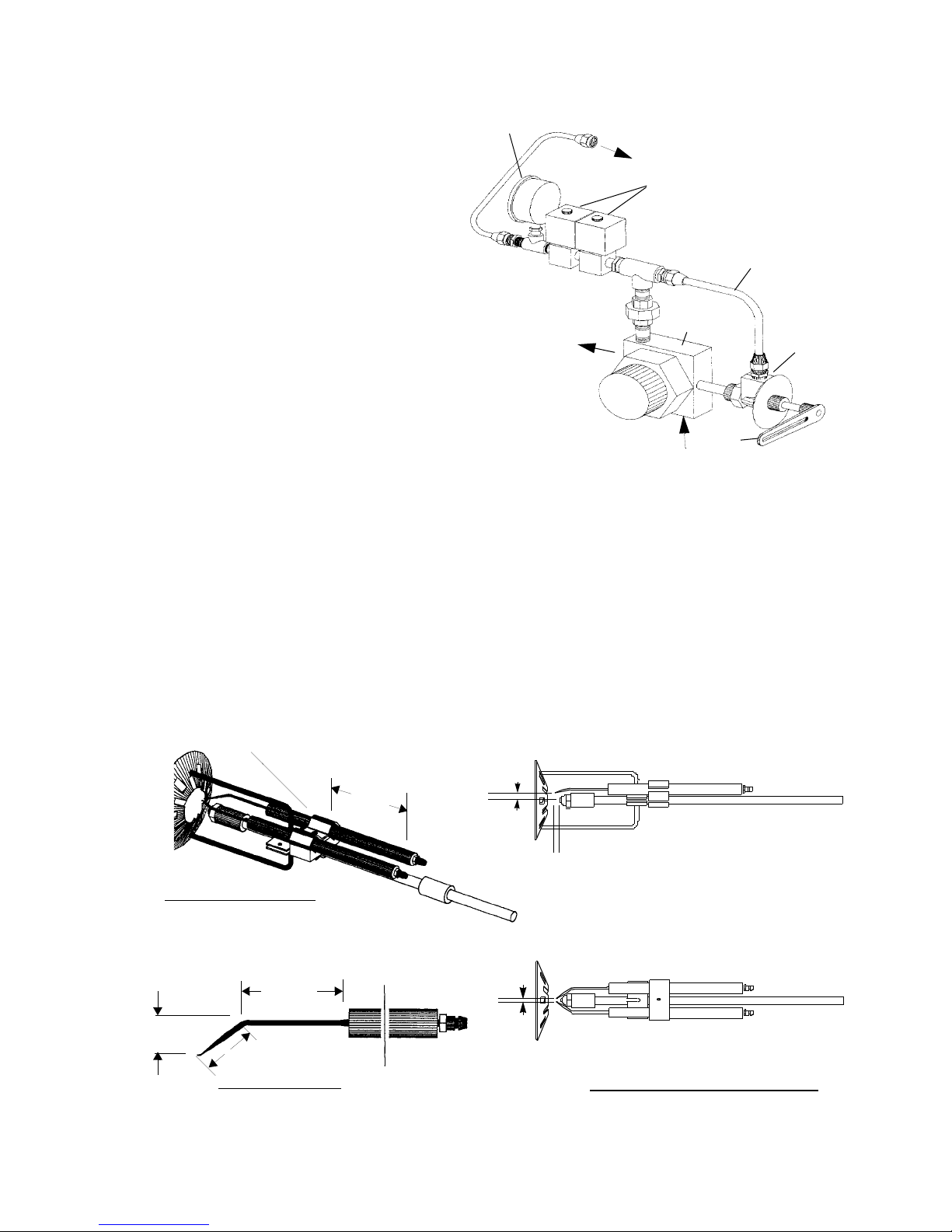
STARTING AND OPERATING INSTRUCTIONS Chapter 5
B. STARTUP PROCEDURES
PRESTART TASKS AND CHECKLIST - ALL
FUELS
Before proceeding with system startup and adjustment, be
sure that overall installation is complete. Review the boiler
operating and installation manual set carefully to verify that
the boiler is properly set up for operation. Check that all
shipped-loose items (those items not installed when shipped)
have been correctly installed. Verify the supply of fuel. Check
to make sure the burner is wired as shown on the wiring
diagram. Ensure that all control wiring terminals are tight.
Complete the following checklist in preparation for system
startup:
• Confirm that the fuel and electrical connections have
been completed in accordance with the applicable codes
and insurance requirements (if necessary), and that con
nections comply with the piping schematic and wiring
diagram.
• Check the combustion air fan motor for correct rotational direction.
• Check that the boiler is filled with water to the proper
level, and that all circulating pumps (hot water units) are
correctly installed and operational.
• Verify that there is proper gas pressure at the gas train,
if this is a gas or combination burner. See the burner
specification plate (Figure 5-8) for minimum and maxi
mum natural gas pressure requirements.
OIL PRESSURE
GAUGE
OIL TO BURNER
OIL SOLENOID VALVES
OIL BYPASS
TUBING
EXCESS OIL
RETURN TO TANK
-
OIL SUPPLY INLET
OIL PUMP
OIL
VALVE
ARM
OIL
METERING
VALV E
Figure 5-4: Oil Piping Schematic
• For oil burners confirm that the oil tank is adequately
filled with the correct grade of fuel oil, and that any iso
-
lation valves in the supply and return lines are open.
• Check that the flame safeguard has been properly installed inside the control panel.
• Provide the following test equipment on site:
-
1) Combustion analyzer for O2.
SET GAP 7/16”
SPARK IGNITION CLAMP
MOUNTED ELECTRODES
19/32
1
1
ELECTRODE SHAPE
3-1/2
1-15/16
ABOVE CENTER
LINE OF NOZZLE
SET GAP 1/4”
AHEAD OF NOZZLE
SET GAP 1/8
BETWEEN
ELECTRODES
ELECTRODES - TO NOZZLE POSITION
Figure 5-5: Direct Spark Ignition Electrode Adjustment Dimensions
750-177 5-5
Page 46

Chapter 5 STARTING AND OPERATING INSTRUCTIONS
DIFFUSER
OIL PIPE
AIR
BAFFLE
HI GH V OLTAG E
IGNITER CABLE
GAS ELECTRIC
PILOT ASSEMBLY
ITEM KEY SIZE 1 SIZE 2 SIZE 3 SIZE 4
CHOKE CONE
DIFFUSER - TO - AIR BAFFLE
ALIGNMENT DIMENSION
B
Diffuser To
Air Baffle
B 1-11/16 2-1/4 3-1/8 3-1/8
Figure 5-6: Blast Tube
ITEM KEY SIZE 1 SIZE 2 SIZE 3 SIZE 4
Nozzle To
Diffuser
A 5/8 11/16 3/4 1-1/16
Figure 5-7: Nozzle / Diffuser / Air Baffle Alignment
2) U-tube manometer, or pressure gauge, to measure
gas pressures (main and pilot).
3) Inclined manometer to measure draft pressures.
4) Smoke spot tester for oil fired units. CO analyzer
for gas fired burners.
5) Voltmeter.
6) Thermometers and thermocouples.
DIFFUSER
A
OIL NOZZLE
OIL NOZZLE
ADAPTER
DIFFUSER CLAMP
OIL PIPE
!
WARNING
DANGER
Attempting initial burner startup with
insufficient knowledge of the equipment
and startup procedures can result in
serious damage to the equipment. The
operator must be totally familiar with the
entire startup and adjustment process
before attempting to operate the burner.
Failure to follow these instructions can
result in seoious personal injury or death
5-6 750-177
Page 47

STARTING AND OPERATING INSTRUCTIONS Chapter 5
AIR AND FUEL CONTROLS
(DESCRIPTION)
The combustion system air and fuel controls have been
factory adjusted, and the unit has been test fired before it was
shipped. Regardless of preliminary adjustment and operation,
it is necessary to readjust the controls for local conditions:
• The fuel flow controls must be adjusted to establish the
rated heat input over the full range of firing-rate modula
tion.
• The air controls need to be adjusted, relative to the established fuel flow rates, to provide the correct amount of
air for complete, efficient combustion.
Fuel and air adjustments are similar on all ProFire burners,
whether gas-fired, oil-fired, or combination gas/oil fired. The
following topics describe air and fuel flow rate adjustments,
and the combustion set-point objectives for optimum
combustion performance:
A. AIR FLOW ADJUSTMENTS
ProFire burners have a unique air shutter design that enables
precise, independent, air flow rate adjustment for both the
high-fire and the low-fire operating points. This design
incorporates a variable main air shutter (mounted on a shaft
and direct-coupled to the modulating motor), plus two
adjustable, but non-modulating, air shutters.
The modulating main air shutter regulates the flow of inlet air
through the fan at flow rates between high-fire and low-fire
conditions. One non-modulating air shutter (for high-fire
combustion air control) is adjusted to provide the correct
amount of air while the system is operating at the high-fire
fuel input rate with the main air shutter fully open. The other
non-modulating shutter (low-fire combustion air control) is
adjusted to provide the correct amount of air with the system
operating at the low-fire fuel input rate with the main shutter
completely closed.
The three air shutters are mounted inside the airbox assembly.
The high-fire and low-fire air shutters are mounted on
independent shafts. A pointer, mounted on each shaft,
indicates the set position of each non-modulating shutter.
Adjustment of these shutters is accomplished by loosening a
setscrew that holds the shutter shaft within a stationary collar
mounted on the airbox.
B. COMBUSTION SETTINGS
Fuel and air flow rates are individually adjusted at low fire
and at high fire to achieve rated heat input, firing rate
turndown, optimum efficiency, safe operation, and the ability
to cope with environmental changes (including air
temperature, humidity, barometric pressure,) and fuel
property changes. Adjustments may be required to meet
certain environmental emissions criteria, such as NOx or CO.
Combustion adjustments also vary with specific system
applications.
750-177 5-7
Turndown capability for oil is less than that for natural gas.
Therefore, on combination fueled burners, gas turndown
performance may be restricted (or determined) by the excess
air levels set initially for oil combustion.
Two key components residing in flue gas are used to optimize
combustion efficiency; excess air and unburned fuel. The
system should be adjusted to the minimum excess air quantity
that provides low levels of unburned fuel with sufficient
-
remaining oxygen to cope with normal atmospheric and fuel
related changes. Unburned fuel is measured as carbon
monoxide (CO) when burning natural gas, and smoke spots
when burning oil.
ProFire burners are capable of operating at CO levels of less
than 50 ppm at all firing rates. The burner should be set-up
and maintained to yield smoke spot levels less than a #2 spot
(ASTM D2156 Shell-Bacharach Scale) to minimize soot
build-up in the boiler.
C. BURNER ADJUSTMENTS,
SINGLE FUEL NATURAL GAS
Note: The operator must consider and allow
for normal variations in air and fuel, which
would reduce the range of excessive
oxygen in the flue gas accordingly.
This section provides detailed procedures for setup and
adjustment of a gas-fired combustion system. Similar
discussions are also presented in this chapter for startup and
adjustment of oil-fired and combination-fueled gas or oil
systems.
These procedures assume that the pre-startup tasks,
checklists, and adjustments have been completed, and that the
boiler system is prepared for initial startup. All necessary test
equipment, should be available on site and installed.
!
WARNING
DANGER
Attempting initial burner startup with
insufficient knowledge of the equipment
and startup procedures can result in
serious damage to the equipment. The
operator must be totally familiar with the
entire startup and adjustment process
before attempting to operate the burner.
Failure to follow these instructions can
result in serious personal injury or death
CONTROLS SETUP. Complete the following burner system
control setup steps before beginning the natural gas startup
procedure:
1. Check the linkages to confirm they are securely fastened
and ready for operation (see Figure 5-9 and 5-11).
Page 48

Chapter 5 STARTING AND OPERATING INSTRUCTIONS
TM
ProFire
Packaged B urner System
Press.
(PS I)
(LPC)
Input Range
Gamme De
Puissance
Max.
Min .
Gas (CFH)
Gaz (PC H)
Press.
( In. WC )
(Po. col . d'eau)
L i qu id (G PH )
Fl u i de (G P H )
Fuel Type Heati ng Value
Ty pe d e c omb ust ibl e
Load
Charge
Main
Circuit princ ipal
Cont rol Circuit
Circuit d e con trole
Fan Mot or
Moteur du vent ilateur
Air Compres sor
Compresseur d 'air
Circulating Pump
Pompe Circulating
Oil Heater
Chaleur Huile
Cont rol Circuit
Circuit d e con trole
Transformer
Current Characteristics
Valeu r calorifique
Carateristiques Electriq ues
PRIMARY
S ECO NDAR Y
Cleave r
SPECIFICATION PLATE
HP VOLTS
Brooks
MILWAUKEE, W I SC O N SI NDIVISION O F A QUA - C HE M , INC.
Overfire Draft (Max.)
T ir age m aximu m
dan s le fo ye r
(I n. W . C. )
(Po. col . d'eau)
PH.
HZ. AMPS.
R
FUSE
B
O
I
MODEL FUEL SERIES S IZE PRESSURE CAPACITY
SERIAL NO.
INSTALL ON NON-COMBUSTIBLE F LOOR. MIN . CLEARANCES FROM COMBUSTIBLE MATERIAL:
STRATFORD, ONT.
3
THOMASVILLE, GA.
3
R
L
E
M
FR ONT 48", REAR 18", SIDES 18" , TOP & FL UE PIPES 18"
ADEQUATE ACCESS MUST BE MAINTAINED F OR SERVICE.
O
/
4
1
"
D
E
L
O
N
1
Cleaver
D IV. , AQ UA -CH E M, INC.
NAME PLATE
.
2
Brooks
MIL WAUK EE , W IS CONSI N
7
4
9
2
-
8
1
1
Figure 5-8: ProFire Burner Nameplate and Specification Plate
5-8 750-177
Page 49

STARTING AND OPERATING INSTRUCTIONS Chapter 5
NOTE: The linkages have been factory-set
and tested, although they may require fine
adjustment for the specific application. If
the linkage is not in place, or if the setting
has been lost, install the linkage in
accordance with Figure 5-9.
2. Place the burner switch to the OFF position.
3. Place the Manual/Auto mode switch to the MANUAL
position.
4. Place the manual flame control potentiometer in the
CLOSED (low-fire) position.
5. Check the presetting of the air shutters. (If the linkage is
loose and no pre-settings are available, start with the
shutter in the full open position).
STARTUP. Proceed with startup of the natural gas-fired system as follows:
1. Close the manual shutoff valves on the burner gas train.
2. Turn on electrical power for the burner, boiler, and
related components.
3. Place the upstream manual gas valve in the on position,
allowing natural gas to enter the gas train. (furthest from
the burner). Reset Low Gas Pressure Switch (if
applicable).
4. Verify that the gas metering valve is nearly closed.
5. Turn the burner switch on. This will start the blower
motor and initiate the prepurge sequence.
6. When the prepurge sequence ends, the pilot valve will
open. The pilot flame should be visible from the viewing
window.
7. When the pilot is established, the flame safeguard will
energize the main gas valve (this is accompanied by fuel
valve activity and illumination of the FUEL VALVE
light). The main gas valve should be visually checked by
observing the stem move from the CLOSED to the
OPEN position.
NOTE: For initial boiler startup, the
downstream manual gas shutoff valve
should be in the closed position to ensure
proper operation of the automatic gas
valves. This valve can then be slowly
opened when the pilot is established and
proven.
8. After the main flame has been established, the gas
manifold pressure entering the burner should be read
(using the pressure tap between the butterfly valve and
the blast tube) to determine an initial estimate of the gas
input rate and compare to Figure 5-10. This will provide
an approximation of the burner input. Obtain a stable
operating point by adjusting the butterfly valve to the
750-177 5-9
pressure indicated in Figure 5-10, and select the
temporary firing rate. This rate for startup is not critical,
but merely an acceptable starting point to begin the high
fire adjustment procedures.
9. After a few seconds, the 02 analyzer should have an
accurate reading of the 0
1 shows the acceptable 0
Normally, 0
levels are set between 3 and 5 percent at
2
present in the flue gas. Table 5-
2
range for the gas burner.
2
low fire, depending on the application and burner size
(see the burner specification plate for the minimum firing
rate).
10. Operate the boiler at low fire until it is up to operating
pressure (steam) or temperature (hot water). Then
increase the fuel input to the boiler by turning the manual
flame control potentiometer towards OPEN in small
increments. This will cause the butterfly valve to open,
allowing more gas into the burner. While increasing the
input, observe that the 0
levels remain within the range
2
listed in Table 5-1. Adjust the gas pressure regulator, as
necessary, to correct this situation. Continue to do this
until the burner reaches high fire (the potentiometer is at
the open position).
11. Adjust the high fire gas input to match the maximum
rating. At high fire, the butterfly valve should be near the
full open position. Adjust gas pressure to obtain the
correct fuel input. (Maximum pressure is specified on the
burner specification plate.)
If a dedicated gas meter is available, the following formula may be used to check fuel flow. Conduct this measurement while operating at a constant rate.
Note: Some meters may require 6.0 IN. H20
correction to Pgas. Consult meter
calibration data.
Gas Input = (HHV) x
Patm + Pgas
29.92
520
Tgas + 460
3600
s
xxx
hr
RATE
3
Btu
ft
=
s
hr
Where:
HHV = The higher heating value of natural gas (1000
3
). Contact your local gas company for an exact
Btu/ft
measurement.
P
= Atmospheric pressure in inches of mercury.
atm
P
= Gas pressure ahead of the volumetric flow meter
gas
in inches of mercury.
T
= Gas temperature at the volumetric flow meter in
gas
°F.
RATE = Natural gas rate taken with the volumetric flow
3
meter in ft
/second.
S = Seconds.
12. Adjust the high fire excess air rate using the high-fire
shutter adjustment (see Figure 5-9 for location).
Page 50

Chapter 5 STARTING AND OPERATING INSTRUCTIONS
DESCRIPTION
1.5 2.0 2.5 3.0 3.5 4.0 4.5 5.0 5.5 6.0 7.0 8.0 9.0 10.0 11.0 12.0
LINKAGE ARM ANGULAR ORIENTATION (IN DEGREES)
1 Main Shaft Gas Valve Arm (Combination)31302532353050202323252522504545
2 Main Gas Valve Arm (Combination) 54 65 52 72 70 70 60 45 45 45 45 45 46 55 55 40
1 Main Shaft Gas Valve Arm (Gas Only) 31303032352525202323252522504545
2 Main Gas Valve Arm (Gas Only) 50555565657055403840404040555540
3 Butterfly Valve Setting (Combination) 34 25 22 25 30 25 25 25 25 25 27 25 24 20 20 20
3 Butterfly Valve Setting (Gas Only) 28182520252020202025202020202020
ROD CLAMP POSITION FROM CENTER POINT (IN INCHES)
1 Main Shaft Gas Valve Arm (Combination) 2.38 2.13 2.13 2.50 2.50 3.25 2.75 3.50 3.75 3.75 3.50 3.50 3.50 2.75 2.50 2.50
2 Main Gas Valve Arm (Combination) 2.50 3.00 3.63 3.50 4.00 3.50 4.25 4.50 4.25 4.25 4.25 4.25 4.50 4.50 4.50 4.50
1 Main Shaft Gas Valve Arm (Gas Only) 2.38 2.50 2.25 2.50 2.50 3.25 3.50 3.50 3.75 3.75 3.50 3.50 3.50 2.75 2.50 2.50
2 Main Gas Valve Arm (Gas Only) 2.50 3.00 2.25 3.50 3.50 3.50 3.25 4.50 4.25 4.25 4.25 4.25 4.50 4.50 4.50 4.50
INPUT RATE MMBtu/hr.
9
LEGEND
1. MAIN SHAFT GAS VALVE ARM
2. MAIN GAS VALVE ARM
3.BUTTERFLY VALVE
4. LINKAGE CONNECTING ROD
5. BALL JOINT
6. HIGH-FIRE AIR SHUTTER HANDLE
7. LOW-FIRE AIR SHUTTER HANDLE
8. MAIN AIR SHUTTER SHAFT
9. GAS MANIFOLD PRESSURE TAP
Figure 5-9: Natural Gas System Control Linkage
5
3
2
0°
4
7
90°
1
6
8
180°
5
5-10 750-177
Page 51

STARTING AND OPERATING INSTRUCTIONS Chapter 5
2
13. Modulate the burner to low fire. The butterfly valve
!
should be adjusted to provide the correct fuel flow and
CAUTION
DANGER
pressure at the low-fire position in accordance with the
burner data plate minimum gas-pressure rating.
This burner is designed to burn only those fuels
shown on the burner data plate. Burning fuels
14. Adjust the low-fire (see Figure 5-9) damper again to
obtain the correct low-fire excess air level within the
range of 3-5% O
.
2
not specified on the data plate could cause
damage to the equipment.
D. BURNER ADJUSTMENTS,
SINGLE FUEL, OIL-FIRED
This section of the manual presents detailed procedures for
The following procedures assume that the pre-startup tasks,
checklists, and adjustments have been completed, and that the
boiler system is prepared for initial startup. All necessary test
equipment should be available on site.
initial startup of an oil-fired combustion system.
Note: The operator must consider and allow for
normal variations in air and fuel, which would
reduce the range of excessive oxygen in the
flue gas accordingly.
Attempting initial burner startup with
!
WARNING
DANGER
insufficient knowledge of the equipment
and startup procedures can result in
serious damage to the equipment. The
operator must be totally familiar with the
entire startup and adjustment process
before attempting to operate the burner.
failure to follow these instructions could
result in serious personal injury or death
23.0
22.0
21.0
20.0
19.0
18.0
17.0
16.0
15.0
14.0
13.0
12.0
11.0
10.0
9.0
8.0
7.0
GAS MANIFOLD PRESSURE (INCHES OF H
6.0
5.0
4.0
3.0
2.0
1.0
0.0
0.0 1.0 2.0 3.0 4.0 5.0 6.0 7.0 8.0 9.0 10.0 11.0 12.0 13.0
SIZE 1
SIZE 2
3.0 - 3.5 MMBtu/hr
SIZE 3
5.0 - 6.0 MMBtu/hr
SIZE 2
3.5 - 4.5 MMBtu/hr
INPUT (MM Btu/hr )
SIZE 3
7.0 - 9.0 MMBtu/hr
SIZE 4
9.0 - 12.0 MMBtu/hr
NOTES:
1. The excess air setting should be sufficient to allow normal
variations in air and
fuel without abnormal
excess air levels, per
Table 5-1.
2. Do not operate the
burner at firing rates
or fuel pressures
higher than the maximum, or lower than
the minimum indicated on the burner
specification plate as
shown in Figure 5-8.
750-177 5-11
Figure 5-10: Natural Gas Input Pressure Curves
Page 52

Chapter 5 STARTING AND OPERATING INSTRUCTIONS
CONTROLS SETUP. Complete the following combination
system control setup steps before beginning the oil-fired
burner startup procedure:
1. Check the linkages to confirm that they are securely
fastened and ready for operation (see Figure 5-11).
NOTE: The linkages have been factory-set
and tested, although they may require fine
adjustment for the specific application. If
the linkage is not in place, or if the setting
has been lost, install the linkage in
accordance with Figure 5-11.
2. Place the burner switch to the OFF position.
3. Place the Manual/Auto mode switch to the MANUAL
position.
4. Place the manual flame control potentiometer to the
CLOSED (low-fire) position.
5. Check the presetting of the air shutters. (If the linkage is
loose and no pre-settings are available, start with the
shutter in the full open position).
6. When a gas pilot is used, open the valve in the gas pilot
line.
STARTUP. Proceed with initial startup of the oil-fired system
as follows:
1. Turn on the electrical power for the burner, boiler, and
related components.
2. Verify that the oil metering valve is nearly open.
NOTE: Opening the oil metering valve
reduces oil flow to the burner.
3. Turn the burner switch on. This will start the blower
motor and initiate the prepurge sequence.
4. When the prepurge sequence ends, the pilot valve will
open. The pilot flame should be visible from the viewing
window.
NOTE: If the pilot is established, the flame
safeguard will energize the two oil solenoid
valves (this is accompanied by a click from
the solenoid valves and illumination of the
FUEL VALVE light) and the oil burner should
ignite on low-fire.
5. After the main flame has been established, the oil
pressure entering the burner nozzle should be read (by
reading the oil pressure gauge downstream of the oil
solenoid valves) to get an initial estimate of the fuel oil
input rate. Oil pressure should be about 80 psi when
operating at low-fire. Adjust the oil metering valve if the
actual pressure is not within the range of 80 to 90 psi.
INPUT
(MMBtu/hr)
MINIMUM O2
(%)
MAXIMUM O2
(%)
SIZE 1
0.7 3.0 9.0
0.9 3.0 9.0
1.0 3.0 9.0
1.5 2.5 9.0
2.0 2.0 5.5
2.5 2.0 5.0
SIZE 2
1.5 3.0 8.0
2.0 3.0 8.0
2.5 3.0 8.0
3.0 3.0 8.0
3.5 3.0 7.0
4.0 3.0 5.0
4.5 3.0 5.0
SIZE 3
4.5 2.5 7.5
5.0 2.5 7.5
5.5 2.5 7.0
6.0 2.5 6.5
6.5 2.5 6.0
7.0 2.5 5.5
7.5 2.5 5.0
8.0 2.5 5.0
8.5 2.5 5.0
9.0 2.0 4.5
SIZE 4
10.0 2.5 5.0
11.0 2.5 5.0
12.0 2.0 4.5
Note: Table presents the maximum recommended range
of operating levels of excess oxygen in the flue gas for
various burner sizes, operating at given levels of natural
gas input to the burner. Data is valid for conditions at standard atmospheric temperature and pressure. Results will
vary under environmental conditions differing from standard.
Table 5-1: Recommended Stack Gas 02
Concentration at Various Rates (Natural Gas)
6. Operate the boiler at low fire until it is thoroughly
warmed. Then, modulate to high fire by turning the
manual flame potentiometer to the OPEN position. This
will cause the oil metering valve to close, resulting in an
increase in the oil pressure feeding the burner nozzle.
Check the excess air in the flue gas (see Table 5-2 for
acceptable O
levels), while modulating to high-fire.
2
Adjust the oil pressure if needed.
5-12 750-177
Page 53

STARTING AND OPERATING INSTRUCTIONS Chapter 5
7. Set the high-fire fuel input pressure to match the
maximum oil pressure specification on the burner data
plate by adjusting the fuel input. The oil metering valve
should be in the fully closed position and the fuel
pressure should be set to the nameplate pressure.
NOTE: Refer to the curves of burner input
rate versus oil pressure (Figures 5-12, 5-13
and 5-14) to determine the oil input rate at
any given oil pressure for the specific
installed burner nozzle size. Nozzle capacity
is stamped on the nozzle body.
8.
DESCRIPTION
1.5 2.0 2.5 3.0 3.5 4.0 4.5 5.0 5.5 6.0 7.0 8.0 9.0 10.0 11.0 12.0
LINKAGE ARM ANGULAR ORIENTATION (IN DEGREES)
1 Main Shaft Oil Controller Arm 88 94 106 110 110 115 115 125 120 120 120 120 120 130 125 105
2 Oil Controller Arm 806652654575751409590905555507050
ROD CLAMP POSITION FROM CENTER POINT (IN INCHES)
1 Main Shaft Oil Controller Arm 2.38 3.38 2.56 3.25 3.253.003.002.253.253.253.503.253.504.254.254.25
2 Oil Controller Arm 2.13 2.63 1.81 2.25 2.25 3.503.503.502.752.753.002.002.003.0 2.752.25
OIL VALVE SETTING (METERING SCALE ON VALVE)
3 Oil Valve Metering Scale setting 13 15.5 17.5 14 13.5 11 10 6 12.5 9.5 10 17.5 17 ***
9. Size 4 burners utilize return flow nozzles rather than
simplex nozzlesused in smaller sizes. See Table 5-3 for
nozzle size and oil pressure.
10. Adjust the high-fire shutter to obtain the correct excess
air level (see Figure 5-11 for the adjustment location).
11. Modulate to low fire using the manual flame control in
accordance with Table 5-2.
12. Set the proper fuel input for low fire by adjusting the
linkage to drive the oil metering valve to the proper
position (see Figure 5-11 for oil metering valve linkage
adjustments).
INPUT RATE MMBtu/hr.
LEGEND
1. MAIN SHAFT OIL CONTROLLER ARM
2. OIL CONTROLLER ARM
3. OIL VALVE METERING SCALE
4. OIL METERING VALVE SHAFT
5. MAIN AIR SHUTTER SHAFT
6. LINKAGE CONNECTING ROD
7. BALL JOINTS
8. HIGH-FIRE AIR SHUTTER HANDLE
9. LOW-FIRE AIR SHUTTER HANDLE
Figure 5-11: Oil Fired System Control Linkage
* Factory Set
3
4
2
6
9
8
7
1
5
90°
0°
180°
750-177 5-13
Page 54

Chapter 5 STARTING AND OPERATING INSTRUCTIONS
13. Check intermediate positions for proper combustion.
Adjust the linkage, as required, to match the fuel and air
rates indicated in Table 5-2.
14. Modulate and recheck combustion air at different firing
rates. When large adjustments are made at one rate, they
may adversely affect settings at another rate.
E. BURNER ADJUSTMENTS,
COMBINATION GAS AND OIL
Note: The operator must consider and allow
for normal variations in air and fuel, which
would reduce the range of excessive
oxygen in the flue gas accordingly.
This section of the manual presents procedures to be followed
for initial startup of a combination ProFire burner.
!
CAUTION
DANGER
This burner is designed to burn only those fuels
shown on the burner data plate. Burning fuels
not specified on the data plate could cause
damage to the equipment.
These procedures assume that the pre-startup tasks,
checklists, and adjustments have been completed, and that the
boiler system is prepared for initial startup. All necessary test
equipment should be available on site.
In general, the combination fueled system is to be started first
using oil, because, as a fuel, oil has a greater combustion air
requirement than natural gas. After being completely
adjusted for oil combustion, the burner is re-started and
adjusted using natural gas as fuel. Combustion adjustment of
the combination burner for natural gas involves balancing the
input gas rates only against the existing flow of combustion
air, as established initially for oil-firing.
air shutters when tuning the combination burner for
combustion of natural gas.
!
WARNING
DANGER
Attempting initial burner startup with
insufficient knowledge of the equipment
and startup procedures can result in
serious damage. The operator must be
totally familiar with the entire startup and
adjustment process before attempting to
operate the burner.
CONTROLS SETUP. Complete the following system control
setup steps before beginning the combination burner startup
procedure:
Do not readjust the
1. Check the linkages to confirm that they are securely
fastened and ready for operation (see Figures 3-2 and 3-
4).
NOTE: The linkages have been factory-set and
tested, although they may require fine tuning for
the specific application. If the linkage is not in
place, or if the setting has been lost, install the
linkage in accordance with Figures 5-9 and 5-
11.
2. Place the burner switch in the OFF position.
3. Place the Modulating Mode switch in the MANUAL
position.
INPUT
(MMBtu/hr)
MINIMUM O2
(%)
MAXIMUM O2
(%)
SIZE 1
0.7 N/A N/A
0.9 4.0 9.5
1.0 4.0 9.5
1.5 2.5 8.0
2.0 2.0 5.0
2.5 2.0 5.0
SIZE 2
1.5 4.0 10.0
2.0 4.0 10.0
2.5 3.5 10.0
3.0 3.0 9.5
3.5 3.0 7.0
4.0 3.0 5.0
4.5 3.0 5.0
SIZE 3
4.5 3.0 8.5
5.0 3.0 8.5
5.5 2.5 8.0
6.0 2.5 7.0
6.5 2.0 6.0
7.0 2.0 5.0
7.5 2.0 5.0
8.0 2.0 5.0
8.5 2.0 5.0
9.0 2.0 4.5
SIZE 4
10.0 3.0 5.0
11.0 3.0 5.0
12.0 3.0 4.5
Note: Table presents the maximum recommended range of operating levels
of excess oxygen in the flue gas for various burner sizes, operating at given
levels of light oil input to the burner. Data is valid for conditions at standard
atmospheric temperature and pressure. Results will vary under environmental conditions differing from standard.
Table 5-2: Recommended Stack Gas O
2
Concentration At Various Rates (Light Oil)
5-14 750-177
Page 55

STARTING AND OPERATING INSTRUCTIONS Chapter 5
4. Place the manual flame potentiometer in the CLOSE
(low-fire) position.
5. Check the presetting of the air shutters. (If the linkage is
loose and no pre-settings are available, start with the
shutter in the full open position).
6. When a gas pilot is used, open the valve in the gas pilot
line.
STARTUP. Proceed with initial startup using oil as follows:
1. Position the fuel selector switch (located inside the
control panel) to OIL.
2. Proceed with startup and combustion adjustments using
the same procedures defined for oil-fired burner initial
startup.
NOTE: Select the appropriate burner nozzle size curve based on the burner
size and capacity stamped on the burner nameplate (see Figure 5-8).
3. After the system has been completely adjusted for oilfiring, place the burner switch to the off position, and
position the fuel selector switch to GAS.
4. Place the Manual/Auto mode switch to the MANUAL
position.
5. Place the manual flame control potentiometer to the
CLOSE (low-fire) position.
6. Close the downstream manual shutoff valve on the
burner gas train (closest to the burner).
7. Admit natural gas to the gas train.
8. Verify that the butterfly valve is in a position that is
nearly closed.
9. Turn the burner switch on. This will start the blower
motor and initiate the prepurge sequence.
Figure 5-12: Burner Input vs. Oil Pressure and Nozzle Size (Size #1 Burners)
750-177 5-15
Input (MMBtu/hr.)
Page 56

Chapter 5 STARTING AND OPERATING INSTRUCTIONS
10. When the prepurge sequence ends, the pilot valve will
open. The pilot flame should be visible from the viewing
window.
11. When the pilot is established, the flame safeguard will
energize the main gas valve (this is accompanied by fuel
valve activity and illumination of the FUEL VALVE
light). The main gas valve should be visually checked by
observing the stem move from the CLOSED to the
OPEN position.
NOTE: The downstream manual gas shutoff
valve should be in the closed position, for
initial boiler startup, to ensure proper
operation of the automatic gas valves. This
valve can then be slowly opened when the
pilot is established and proven.
12. After the main flame has been established, the gas
pressure entering the burner should be read (using the
pressure tap between the butterfly valve and the blast
NOTE: Select the appropriate burner nozzle size curve based on the burner
size and capacity stamped on the burner nameplate (see Figure 5-8).
tube) to determine an initial estimate of the gas input rate.
By doing so, and referring to Figure 5-10, an
approximation of the burner input can be assessed.
Obtain a stable operating point by adjusting the butterfly
valve to the pressure indicated in Figure 5-10 and select
the temporary firing rate. This rate for startup is not
critical, but merely an acceptable starting point to begin
the high fire adjustment procedures.
13. After a few seconds, the O2 analyzer should have an
accurate reading of the O
5-1 provides a representation of the acceptable O
for the gas burner. Normally, the O
present in the flue gas. Table
2
levels are set
2
range
2
between 3 and 5 percent at low fire, depending on the
application and burner size (see the burner specification
plate for the minimum firing rate).
14. Operate the boiler at low fire until it is thoroughly
warmed. Then increase the fuel input to the boiler by
turning the manual flame potentiometer towards open in
Figure 5-13: Burner Input vs. Oil Pressure and Nozzle Size (Size #2 Burners)
5-16 750-177
Input (MMBtu/hr.)
Page 57

STARTING AND OPERATING INSTRUCTIONS Chapter 5
small increments. This will cause the butterfly valve to
open farther, allowing more gas into the burner. While
increasing the input, observe that the O
levels remain
2
within the range shown in Table 5-1. Adjust the gas
pressure regulator, as necessary, to correct this situation.
Continue to do this until the burner reaches high fire (the
potentiometer is at the open position).
15. Adjust the high fire gas input to match the maximum
rating. At high fire, the butterfly valve should be near the
full open position (readjust linkage if required). Adjust
the gas pressure to obtain the correct fuel input.
(Maximum pressure specified on the burner specification
plate.)
If a dedicated gas meter is available, the following formula may be used to check fuel flow. Conduct this measurement while operating at a constant rate.
Gas Input = (HHV) x
Patm + Pgas
29.92
520
Tgas + 460
NOTE: Select the appropriate burner nozzle size curve based on the burner
size and capacity stamped on the burner nameplate (see Figure 5-8).
3600
s
xxx
hr
RATE
3
Btu
ft
=
s
hr
NOTE: Some meters may require 6.0 IN. H20
correction to Pgas. Consult meter
calibration data.
Where:
HHV = The higher heating value of natural gas (1000
3
). Contact your local gas company for an exact
Btu/ft
measurement.
P
= Atmospheric pressure in inches of mercury.
atm
P
= Gas pressure ahead of the volumetric flow meter
gas
in inches of mercury.
T
= Gas temperature at the volumetric flow meter in
gas
°F.
RATE = Natural gas rate taken with the volumetric flow
3
meter in ft
/second
S = Seconds.
750-177 5-17
Figure 5-14: Burner Input vs. Oil Pressure and Nozzle Size (Size 3 Burners)
Input (MMBtu/hr)
Page 58

Chapter 5 STARTING AND OPERATING INSTRUCTIONS
(
)
(
)
NOTE: It is unnecessary to readjust the
position of the high-fire or low-fire shutters
after having been set for oil firing.
16. Modulate the burner to low fire. The butterfly valve
should be adjusted to provide the correct fuel pressure at
the low-fire position in accordance with the burner data
plate minimum gas-pressure rating.
FUEL FLOW ADJUSTMENTS. Fuel flow rates are adjusted
to provide the design-rated heat inputs into the burner at both
high-fire (maximum rate) and low-fire (minimum rate) oper
ating conditions. The maximum and minimum fuel input flow
rates for the burner are identified on the data plate (see Figure
5-8). Natural gas flow rates are specified in cfh (cubic feet per
hour), and fuel oil flow rates are specified in gph (gallons per
hour).
Fuel flow rate adjustment for both natural gas and oil is
accomplished by regulating the fuel pressure against a fixed
diameter orifice (nozzle). The methods for accomplishing the
pressure regulation, however, are different for natural gas and
oil.
-
The method for regulating the natural gas flow rate (manifold
pressure) is as follows:
1. Maximum flow rate is established by operating the
burner at high-fire with the butterfly valve fully open,
then adjusting the manifold pressure to the maximum as
specified on the data plate. Maximum manifold pressure
is obtained by adjusting the main gas pressure regulator
on the gas train while operating the burner at high-fire.
2. Gas flow modulation for turndown is accomplished by
throttling the flow rate with the butterfly valve. The flow
restriction of the partially closed butterfly valve reduces
the flow of gas through the burner nozzle. The butterfly
valve throttling position is controlled by linkage from the
main air shutter shaft, which is operated by the
modulating motor.
With the modulating motor positioned for low-fire operation,
the butterfly valve linkage is adjusted to provide the
minimum pressure in the nozzle manifold, as specified on the
burner data plate.
SIZE 4 BURNERS
INPUT
MMBtu/hr
10 71.4 23.8 200 82
11 78.6 26.2 185 50
12 85.7 28.6 200 40
Note: Oil pressure is return oil pressure and based on 300 psi pump pressure
FLOW RATE
GPH)OIL PRESSURE (PSI
max. min. max. min.
Table 5-3: Size 4 Burner Pressure and Flow
5-18 750-177
Page 59

STARTING AND OPERATING INSTRUCTIONS Chapter 5
The method for regulating the fuel-oil flow rate (nozzle
pressure) is as follows:
1. Maximum flow rate is established by operating the
burner at high-fire with the oil metering valve in a nearly
closed position with the modulating motor set at the
high-fire position. In this position, the flow of fuel oil
through the oil by-pass is minimal, resulting in nearly
maximum flow pressure from the pump. High-fire oil
flow adjustment is accomplished by adjusting the
linkage to the oil metering valve so that the burner nozzle
pressure equals the maximum oil pressure specification
on the burner data plate (see Figure 5-8).
2. Oil pressure modulation for turndown to low-fire
operation is accomplished by increasing the flow rate of
oil through the oil by-pass loop, which reduces pressure
in the burner nozzle. This is accomplished by setting the
modulating motor to the low-fire position, which causes
the oil metering valve to open. While in this position, the
oil metering valve linkage can be adjusted so that the
burner nozzle pressure equals the minimum oil pressure
specification on the burner specification plate (see
Figure 5-8).
F. STARTUP, OPERATING AND
SHUTDOWN - ALL FUELS
Depending upon the fuel being burned, the applicable
previous sections in Chapter 5 should be reviewed for
preliminary instructions.
The fuel selector switch should be, accordingly, set to either
oil or gas.
Set the manual-automatic switch (Figure 2-1) to “manual”
and turn the manual flame control to “close.”
Turn burner switch to “ON.” The load demand light should
glow. The low-water level light should remain out, indicating
a safe water level in the boiler. The programmer is now
sequencing. See Chapter 4 for sequence details.
Note: On an initial starting attempt, several
efforts might be required to accomplish
“bleeding” of fuel lines, main or pilot. If
ignition does not then occur, do not repeat
unsuccessful attempts without rechecking
the burner and pilot adjustment.
On ignition failure, the flame failure light will glow and the
blower will purge the boiler of unburned fuel vapors before
stopping. After ignition failure, wait a few moments before
re-setting the lockout switch.
Do not re-light the pilot or attempt to start
the main burner, either oil or gas, if the
combustion chamber is hot and/or if gas or
oil vapor combustion gases are present in
the furnace or flue passages. Failure to
follow these instructions could result in
serious personal injury or death.
The burner and control system is designed
to provide a “pre-purge” period of fan
operation prior to establishing ignition
spark and pilot flame. Do not attempt to alter
the system or take any action that might
circumvent the “pre-purge” feature. Failure
to follow these instructions could result in
serious personal injury or death.
After main flame ignition, the burner should be set on manual
control at its low fire setting (that is, with manual flame
control at “close”) until the boiler is properly warmed. In the
case of a steam boiler, CLOSE THE VENT VALVE when the
steam begins to appear.
A hot water boiler must have a continuous flow of system
water through the vessel during the warm-up period. The
entire water content of the system and boiler must be warmed
prior to increasing fuel input.
If the flame at low fire provides insufficient heat to reach
normal operating pressure or temperature after 30 minutes,
gradually increase the firing rate by turning the manual flame
control in one point increments. Operate at the increased fuel
input rate for a period of time until an increase is noted in
pressure or temperature.
After the boiler is thoroughly warmed, turn the manual flame
control to high fire. At this point a combustion analysis
should be made, with instruments, and fuel flow regulated as
required. Refer to the adjustment procedures in Chapter 6.
After making the high-fire adjustment, manually decrease the
firing rate to analyze combustion gases, and adjust as
required.
To properly perform the testing and adjusting, it is necessary
that the burner be allowed to fire at a maximum rate long
enough to achieve desired results.
Operating - Normal operation of the burner should be with
the switch in the automatic position and under the direction of
the modulating control. The manual position is provided for
initial adjustment of the burner over the entire firing range.
When a shutdown occurs while operating in the manual
!
WARNING
DANGER
!
WARNING
DANGER
750-177 5-19
Page 60

Chapter 5 STARTING AND OPERATING INSTRUCTIONS
position at other than low fire, the damper will not be in a
closed position, thus allowing more air than desired to flow
through the boiler.
the pressure vessel metal and refractory to undesirables
conditions.
With the switch set at “auto,” the burner will operate on a
modulating basis according to the load demand.
The burner will continue to operate with modulated firing
until the operating limit pressure or temperature is reached,
unless:
1. The burner is manually turned “off.”
2. A low-water condition is detected by low-water level
control.
3. The electrical or fuel supply is interrupted.
4. The combustion air pressure drops below minimum
level.
Note: There can be other reasons for
shutdown such as motor overload, flame
outages, tripped circuit breakers, blown
fuses, or through other interlock devices in
the circuitry.
When the burner is shut down normally, by either the
operating limit control or by manually switching the burner
off, the load demand light no longer glows.
Shutdown through conditions causing safety or interlock
controls to open will actuate the flame failure light (and alarm
if so equipped) and the load demand light will remain lit. The
cause of this type of shutdown will have to be located,
investigated, and corrected before operation can be resumed.
Refer to the troubleshooting section in Chapter 7.
Shutdown - When the operating limit control setting is
reached to open the circuit or if the burner switch is turned
“off,” the following sequence occurs.
The fuel valve is deenergized and the flame is extinguished.
The timer begins operation and the blower motor continues
running to force air through the furnace in the post-purge
period.
At the end of the programmed post-purge period, the blower
motor is turned off. The timer has returned to its original
starting position and stops. The unit is ready to re-start.
The hot flame to cool air cycling subjects
!
WARNING
DANGER
strainers, foreign material in either new or
renovated fuel lines may lodge under a
valve seat and prevent tight closure. The
situation is especially true in new
installations. Promptly correct any
conditions causing leakage. Failure to
follow these instructions could result in
serious personal injury or death
G. CONTROL OPERATIONAL TEST
AND CHECKS
Proper operation of the various controls should be verified
and tested when the boiler is initially placed into service, or
whenever a control is replaced. Periodic checks should be
made thereafter in accordance with a planned maintenance
program.
The operating limit control may be checked by allowing
steam pressure or water temperature to increase until the
burner shuts down. Depending upon the load, it may be
necessary to manually increase the firing rate to raise steam
pressure to the burner shut off point. If the load is heavy, the
header valve can be closed or throttled until the pressure
increases. Observe the steam gauge to check the cut off
pressure as the operating limit control shuts the burner down.
Slowly open the header valve to release steam pressure and
check the cut-in setting as the burner restarts. Check the
modulating control for the desired operating pressure range.
See Chapter 6 for instructions on the adjustment of controls.
The water temperature on a hot water boiler that may be
operating at less than full load may be raised by manually
increasing the firing rate until the burner shuts down through
the action of the operating limit control. Observe the
thermometer to verify the desired settings at the point of cutout and again when the burner restarts. Return the manual
automatic switch to “automatic” and check the modulating
control for the desired temperature range. See Chapter 6 for
instructions on the adjustment of the controls.
Check the proper operation and setting of the low-water
cutoff and the auxiliary low water cutoff (and pump operating
control, if used).
Proper operation of the flame failure device should be
checked at startup and at least once a week thereafter. Refer
to Chapter 8 for information on flame safety checks. Check
the program relay’s annunciation for any system failure.
Observe the promptness of ignition of the pilot flame and the
main flame.
It is advisable to check for tight shut-off of
fuel valves. Despite precautions and
5-20 750-177
Page 61

CHAPTER 6
Adjustment Procedures
A. General. . . . . . . . . . . . . . . . . . . . . . . . . . . . . . . . . . .6-1
B. Linkage - Modulating Motor & Air Damper . . . . . .6-1
C. Modulating Motor . . . . . . . . . . . . . . . . . . . . . . . . . .6-2
D. Modulating Motor Switches -
Low Fire and High Fire . . . . . . . . . . . . . . . . . . . . . .6-2
E. Burner Operating Controls - General. . . . . . . . . . . .6-2
F. Modulating Pressure Control (Steam) . . . . . . . . . . .6-5
G. Operating Limit Pressure Control (Steam) . . . . . . .6-5
H. High Limit Pressure Control (Steam). . . . . . . . . . .6-5
I. Modulating Temperature Control (Hot Water). . . . .6-6
J. Operating Limit Temperature Control (Hot Water) .6-6
K. High Limit Temperature Control (Hot Water) . . . .6-6
Note: If the boiler is not equipped with a
ProFire burner. Please refer to the specific
Operation and Maintenance manual for the
burner supplied.
A. GENERAL
Each Cleaver-Brooks boiler is tested for correct operation
before shipment from the factory. However, variable
conditions such as burning characteristics of the fuel and
operating load conditions may require further adjustment
after installation to assure maximum operating efficiency and
economy.
A combustion efficiency analysis made during the initial
start-up will help to determine what additional adjustments
are required in a particular installation.
Prior to placing the boiler into service, a complete inspection
should be made of all controls, connecting piping, wiring, and
all fastenings such as nuts, bolts and setscrews to be sure that
no damage has occurred, or that adjustments have not
changed during shipment and installation.
The adjustment procedures in Chapter 6 apply to standard
components furnished on steam or hot water boilers fired
with gas and/or the various grades of oil.
L. Lowwater Cutoff Devices . . . . . . . . . . . . . . . . . . . . 6-6
M. Combustion Air Proving Switch . . . . . . . . . . . . . . 6-6
N. Gas Pilot Flame Adjustment . . . . . . . . . . . . . . . . . . 6-6
O. Gas Pressure and Flow Information . . . . . . . . . . . . 6-7
P. Gas Fuel Combustion Adjustment . . . . . . . . . . . . . . 6-8
Q. Low Gas Pressure Switch . . . . . . . . . . . . . . . . . . . . 6-9
R. High Gas Pressure Switch. . . . . . . . . . . . . . . . . . . . 6-9
S. Fuel Oil Pressure and Temperature - General . . . . . 6-9
T. Fuel Oil Combustion Adjustment . . . . . . . . . . . . . 6-10
U. Low Oil Pressure Switch . . . . . . . . . . . . . . . . . . . 6-11
B. LINKAGE - MODULATING MOTOR
AND AIR DAMPER
The linkage consists of various arms, connecting rods, and
swivel ball joints that transmit motion from the modulating
motor to the metering valve, to the air damper, and to the gas
butterfly valve, if used.
When properly adjusted, a coordinated movement of the
damper and metering valves within the limits of the
modulating motor travel is attained to provide proper fuel-air
ratios through the firing range.
In linkage adjustments there are several important factors that
must serve as guides.
1. The modulating motor must be able to complete its full
travel range.
!
CAUTION
DANGER
Do not restrict the full travel of the modulating motor. Failure to follow these instructions could result in equipment damage.
750-177 6-1
Page 62

Chapter 6 Adjustment Procedures
2. Initial adjustment should be made with the motor in full
closed position, that is with the shaft on the power end of
the motor in its most counterclockwise position.
3. The closer the linkage rod connector is to the drive shaft,
the less the arm will travel; the closer the connector is to
the driven shaft, the farther that arm will travel.
Figure 6-1 shows the linkage required for a gas-oil
combination burner. Prior to initially firing a boiler it is
advisable to check for free movement of the linkage. The
damper motor must be allowed to complete its full stroke and
the damper must move freely from low to high fire position.
Adjustment of linkage connected to a gas butterfly valve is
described in Section P of Chapter 6.
C. MODULATING MOTOR
The modulating motor has a 90° shaft rotation. The motor
manufacturer also provides a 160° stroke model for other
applications.
than a Cleaver-Brooks Service or Parts representative, it may
have an incorrect stroke. To prevent damage, verify the 90°
stroke prior to installing a replacement.
The stroke may be determined by powering the motor and
connecting terminals R-B to actually determine the stroke as
motor drives to an open position.
If a replacement is obtained from someone other
D. MODULATING MOTOR SWITCHES
- LOW FIRE AND HIGH FIRE
The modulating motor contains either one or two internal
switches depending upon application. The microswitches are
actuated by adjustable cams attached to the motor shaft.
Factory replacement motors have the cams preset. The low
fire start switch is set to make the red and yellow leads at
approximately 8° on motor closing. The high fire purge air
proving switch (located in the modulating motor) is set to
make red and blue tracer leads at approximately 60° the on
motor opening. Normally the settings are left as is, but job
conditions may require readjustment. If the cams require
adjustment or resetting, follow the instructions in the
manufacturer’s technical manual.
Figure 6-1: Complete Linkage Assembly -
Combination Gas and Oil
E. BURNER OPERATING CONTROLS
- GENERAL
Note: Adjustments to the boiler operating
controls should be made by an authorized
Cleaver-Brooks Service Technician. Refer to
the appropriate boiler Operation and
Maintenance manual for specific
information on boiler startup and operation.
The standard boiler operating control package consists of
three separate controls, the
Limit Control and the Modulating control.
The High Limit Control senses the hot water temperature or
steam pressure. It is used as a safety limit to turn the burner
off in the event the operating limit control fails. The high limit
control should be set sufficiently above the operating limit
control to avoid nuisance shutdowns.
The Operating Limit Control senses temperature or pressure
and automatically turns the burner on to initiate the start-up
sequence when required and turns the burner off to initiate the
shutdown sequence when the demand is satisfied. The control
must be set to initiate startup only at the low fire position.
High Limit Control, Operating
6-2 750-177
Page 63

Adjustment Procedures Chapter 6
The Modulating Control senses changes in the hot water
temperature or steam pressure and signals the modulating
motor to control the flow of fuel and air to the burner. With
either steam or hot water boilers, the modulating control must
be set to ensure the burner is at its minimum low fire position
before the operating limit control either starts or stops the
burner.
When adjusting or setting controls, first be sure all control
devices are securely mounted and level. With the temperature
sensing control, make sure the sensing bulb is properly
bottomed in its well and is secured against movement. Be
sure the connecting tubing is not kinked.
The dial settings are generally accurate; although it is not
Figure 6-2: Steam Controls
unusual to have a slight variation between a scale setting and
an actual pressure gauge or thermometer reading. Always
adjust control setting to agree with pressure gauge or
thermometer readings. Accurate instrument readings are
required. When necessary use auxiliary test equipment to set
controls.
Burner controls correctly set to match load demands will
provide operational advantages and achieve the following
desirable objectives:
• The burner will be operating in low fire position prior to
shut down.
• The burner will operate at low fire for a brief period on
each start during normal operation.
• Eliminates frequent burner on-off cycling.
Separate and independent controls affect modulated firing
and burner on-off cycling. Figure 6-4 depicts a typical setting
relationship of the operating limit control, modulating control
and the high limit control.
The burner will be “on” whenever the pressure or temperature
is less than point B and “off” whenever pressure or
temperature is greater than point A. The distance between
points A and B represents the “on-off” differential of the
operating limit control.
In normal operation, the burner will shut down whenever the
pressure or temperature rises above setting A. At that point
the switch in the operating limit control will open. As the
pressure or temperature drops back to B, the
operating limit
control closes and the burner will restart. The modulating
control will signal the modulating motor to be in a low fire
position. If the load demands exceed the low fire input
potential, the
modulating control will increase the firing rate
proportionately as pressure or temperature falls toward point
D. The modulating motor will stop at any intermediate point
between C and D whenever the fuel input balances the load
requirement.
Figure 6-3: Hot Water Operating Controls
As the load requirement changes, the firing rate will change
accordingly. Thus it is referred to as modulated firing.
750-177 6-3
Page 64

Chapter 6 Adjustment Procedures
100%
Firing Rate
Minimum Input
(Low Fire)
Burner Off
Increasing
Increasing
0%
D
Modulation Control Response
Modulated Firing
Range
Operating Limit Control
Response
C
B
Falling Temp.
or Pressure
“ON - OFF”
Differential
Rising Temp.
or Pressure
(Burner ON)
Boiler Temp.or Press
A
(Burner OFF)
High Limit Control
Safety Shutdown
(Burner OFF)
Increasing
Figure 6-4: Firing Graph
Point D represents the maximum firing rate of the burner, or
highfire. In the event pressure or temperature drops while the
burner is firing at highfire, it indicates that the load exceeds
the capacity of the boiler.
The firing graph (Figure 6-4) shows that point B and point C
do not coincide. Extreme load conditions could require the
points be closely matched.
When set as shown, with a time lag between B and C, the
burner will be in a low fire position upon a restart and will fire
at that rate for a short period of time before falling pressure or
temperature requires an increase in the firing rate.
modulating control range and operating
control range.
When firing a cold boiler, it is recommended that the burner
be kept at low fire, under manual flame control, until normal
operating pressure or temperature is reached. If the burner is
not under manual control on a cold start, it will immediately
move toward high fire as soon as the program control releases
the circuit that holds the burner in low fire. The modulating
control will be calling for high fire and the burner will move
to that position as rapidly as the damper motor can complete
its travel.
Note: Rapid heat input can subject the
pressure vessel metal and refractory to
!
CAUTION
DANGER
Excessive cycling increases the potential
and severity of internal condensation. OnOff cycling should be limited to eight (8) cy
cles or less per hour to keep the blower motor from overheating and excessive wear on
the switch gear and pilot. Failure to follow
these instructions could result in damage
and premature failure of the equipment.
If points B and C overlap when restart occurs, the burner
would drive to a higher firing position immediately after the
main flame was proven.
-
undesirable conditions.
Do not operate the boiler in excess of 90% of the safety valve
relief setting. The closer the operating pressure is to the safety
valve relief pressure, the greater the possibility of valve
leakage. Continued leakage, however slight, will cause
erosion and necessitate early safety valve replacement. The
control settings on a hot water boiler must be within the
temperature limits of the boiler.
Ideally, the boiler operating controls should be set under
actual load conditions. Especially under new construction
conditions, the boiler is initially started and set to operate
under less than full load requirements. As soon as possible
thereafter, the controls should be reset to provide maximum
Note: It is not recommended that the boiler
controls be set so as to overlap the
6-4 750-177
6-4
Page 65

Adjustment Procedures Chapter 6
utilization of the modulating firing system. To accomplish
maximum utilization, and assuming that air/fuel combustion
ratios have been set, make the required adjustments to the
controls to bring the boiler pressure or temperature up to meet
the load requirements.
To properly set the modulating control, carefully adjust it
under load conditions, until the load is maintained with the
burner firing at a steady rate. The firing rate at that point may
be full high fire or slightly less, depending upon the
relationship of the boiler size to the load.
When the modulating control is set and the burner is in full
high fire, the scale setting of the
on a steam boiler will indicate the low point of the modulating
range. The scale setting of the
control on a hot water boiler will have a reading that indicates
the midpoint of the modulating range.
The operating limit control should now be adjusted and the
differential established. In an installation that does not require
a very close control of steam pressure or water temperature
the adjustable differential (Figure 6-4 A to B) should be set as
wide as conditions permit, since a wide setting will provide
less frequent burner cycling.
The high limit control provides a safety factor to shut the
burner off in the event the
The setting of the control should be sufficiently above the
operating limit control to avoid nuisance shutdowns. The
setting, however, must be within the limits of the safety valve
settings and should not exceed 90% of the valve setting. The
control requires manual resetting after it shuts off the burner.
In the setting of the controls, consideration must be given to
the time required for a burner restart. Each start, requires a
prepurge period, plus the fixed time required for proving the
pilot and main flame. In addition, approximately one-half
minute is required for the damper motor to travel from low to
high fire. The time lag may allow pressure or temperature to
drop below desirable limits.
modulating pressure control
modulating temperature
operating limit control should fail.
Figure 6-5: Steam Operating Controls
!
CAUTION
DANGER
To prevent burner shutdown at other than
low-fire setting, adjust the modulating pres
sure control to modulate to low fire BEFORE
the operating limit pressure control shuts
off the burner. Failure to follow these in
structions could result in damage to the
equipment
-
-
G. OPERATING LIMIT PRESSURE
CONTROL (Steam)
Set the “cut-out” (burner-off) pressure on the main scale
using the large adjusting screw. Set the differential on the
short scale by turning the small adjusting screw until the
indicator points to the desired difference between cut-out and
cut-in pressures. The “cut-in” (burner-on) pressure is the cutout pressure MINUS the differential. The cut-out pressure
should not exceed 90% of the safety valve setting.
F. MODULATING PRESSURE
CONTROL (Steam)
Turn the adjusting screw until the indicator is opposite the
low point of the desired modulating range. Modulated firing
will range between the low point and a higher point equal to
the modulating range of the particular control. In 0-15 psi
controls the range is 1/2 psi.
Set “cut-out” (burner off) pressure on the main scale using
the adjusting screw. The control will break a circuit when
pressure reaches this point. The setting should be sufficiently
above the operating limit pressure control to avoid
shutdowns, and preferably not exceed 90% of safety valve
setting. The control requires manual resetting after tripping
on a pressure increase. To reset, allow pressure to return to
normal and then press the reset button.
H. HIGH LIMIT PRESSURE
CONTROL (Steam)
750-177 6-5
Page 66

Chapter 6 Adjustment Procedures
K. HIGH LIMIT TEMPERATURE
CONTROL (Hot Water)
Set the “cut-out” (burner off) temperature on scale using the
lock
123
adjusting screw. The control will break the circuit and
out on a rise in water temperature above the setting. The
setting should be sufficiently above the operating limit
temperature to avoid unnecessary shutdowns. The control
requires manual resetting after tripping on a temperature
increase. To reset, allow the water temperature to drop below
the cut-out setting less differential, and then press the manual
reset button.
L. LOW WATER CUTOFF DEVICES
(Steam and Hot Water)
1. HIGH LIMIT TEMPERATURE CONTROL LIMIT
OPERATING LIMIT TEMPERATURE CONTROL
2.
3. MODULATING TEMPERATURE CONTROL
Figure 6-6: Hot Water Controls
No adjustment is required since LWCO controls are preset by
the original manufacturer. However, if the water level is not
maintained, inspect the devices immediately and replace as
required.
M. COMBUSTION AIR PROVING
I. MODULATING TEMPERATURE
CONTROL (Hot Water)
Turn the knob on the front of the case (see Figure 6-6) until
the pointer indicates the desired setpoint temperature. The
desired set point is the center point of a proportional range.
The control has a 3 to 30° differential and may be adjusted to
vary the temperature range within which modulating action is
desired. With the cover off, turn the adjustment wheel until
pointer indicates desired range.
!
CAUTION
DANGER
To prevent burner shutdown at other than
low-fire setting adjust modulating tempera
ture control to modulate low fire BEFORE
operating limit temperature control shuts
off burner. Failure to follow these instruc
tions could result in damage to the equipment.
-
-
Air pressure against the diaphragm actuates the switch which,
when made, completes a circuit to prove the presence of
combustion air. Since the pressure of the combustion air is at
its minimum value when the damper is full closed, the switch
should be adjusted under that situation. It should be set
slightly below the minimum pressure, but not too close to that
point to cause nuisance shutdowns.
The run/test switch on the program relay should be set to
TEST. Turn the burner switch on. The blower will start
(provided that all limit circuits are completed) and the
programmer will remain in the low-fire (damper closed)
portion of the prepurge.
Slowly turn down the air switch adjusting screw until it
breaks the circuit. Here the programmer will lock out and
must be manually reset before it can be restarted. Add a half
turn or so to the adjusting screw to remake its circuit.
Recycle the program relay to be sure that normal operation is
obtained. Return the test switch to the RUN position.
SWITCH
J. OPERATING LIMIT
TEMPERAT UR E CON TR OL
(Hot Water)
Set “cut-out” (burner off) temperature on the scale by
inserting a screwdriver through the cover opening to engage
the slotted head adjusting screw (see Figure 6-6). The “cutin” (burner on) temperature is the cut-out temperature
MINUS the differential. The differential is adjusted from 5 to
30° F.
6-6 750-177
N. GAS PILOT FLAME ADJUSTMENT
The size of the gas pilot flame is regulated by adjusting the
gas flow through the pilot gas regulator. The flame must be
sufficient to ignite the main flame and to be seen by the flame
detector. But an extremely large flame is not required. An
overly rich flame can cause sooting or carbon buildup on the
igniting electrode. Too small a flame can cause ignition
problems.
Page 67

Adjustment Procedures Chapter 6
Although it is possible to visibly adjust the size of the pilot
flame, it is preferable to obtain a microamp or voltage reading
of the flame signal.
The correct voltage or microamp readings can be found in the
information supplied with the flame safeguard system.
The program relay used may be of the type that provides
message information that includes a constant flame signal of
dc voltage. In this case a separate dc voltmeter is not required.
O. GAS PRESSURE AND FLOW
INFORMATION
Because of variables in both the properties of gas and the
supply system, it will be necessary to regulate the pressure of
the gas to a level that produces a steady, dependable flame
that yields highest combustion efficiency at rated
performance yet prevents overfiring. Once the optimum
pressure has been established, it should be recorded and
periodic checks made to verify that the regulator is holding
the pressure at this level. Occasional modification in fuel
composition or pressure by the supplier may, at times, require
readjustment to return the burner to peak efficiency.
Pressure
The gas supplied must provide not only the quantity of gas
demanded by the unit, but must also be at a pressure high
enough to overcome the pressure-loss due to the frictional
resistance imposed by the burner system and the control
valves.
The pressure required at the entrance to the burner gas train
for rated boiler output is termed “inlet pressure.” The gas
pressure regulator must be adjusted to achieve the pressure to
assure full input.
The inlet pressure requirement varies with boiler size, and
types of gas train. Refer to Table 6-3 for pressure requirements.
The pressures listed are based on 1000 Btu/cu-ft natural gas
at elevations up to 700 feet above sea level.
The volume of gas flow is measured in terms of cubic feet and
is determined by a meter reading. The gas flow rate required
for maximum boiler output depends on the heating value
(Btu/cu-ft) of the gas supplied (Table 6-1).
Pressure Correction
The flow rate outlined in Section P is based on a “base”
pressure, which is usually atmospheric or 14.7 psia.
Meters generally measure gas in cubic feet at “line” or supply
pressure. The pressure at which each cubic foot is measured
and the correction factor for the pressure must be known in
order to convert the quantity indicated by the meter into the
quantity which would be measured at “base” pressure.
To express the volume obtained from an actual meter reading
into cubic feet at base pressure, it is necessary to multiply the
meter index reading by the proper pressure factor obtained
from Table 6-2
As An Example:
Assume that a 500Flextube boiler is rated for 5MMBtu/hr
input is installed and equipped with a standard gas train; and
that 1,000 Btu natural gas is available with an incoming gas
pressure of 3 psig. The flow requirements can be determined
as follows:
Flow
Since the gas flow rate is based on standard conditions of
flow, correction must be made for the supply pressure through
the meter of 3 psig. Determine the flow rate by dividing the
Btu content of the gas into the burner input (Table 6-1) and
“correct” this answer by applying the correction factor for 3
psig (Table 6-2).
Btu/hr Input = CFH (Cubic feet/hour) Required
Btu/cu-ft
OR
5,000,000 = 5,000 CFH (At 14.7 Ib-atmospheric base
1,000 pressure)
THEN
5,000 = 4237 CFH
1.18
This is the CFH (at line pressure) that must pass through the
meter so that the equivalent full input requirement of 5,000
CFH (at base pressure) will be delivered.
Checking Gas Flow
Your gas supplier can generally furnish a gas meter flow chart
from which gas flow can be determined. After a short
observation period, the information aids in adjusting the
regulator to increase or decrease flow as required to obtain the
rating.
Final adjustment of the gas fuel is carried out by means of
Fine tuning the linkage adjustments, while performing a
combustion efficiency analysis. See Section O for details.
Note: The information given in this section
is for all practical purposes sufficient to set
and adjust controls for gas input. Your gas
supplier can, if necessary, furnish exact
correction factors that take into
consideration Btu content, exact base
pressure, specific gravity, temperature, etc.,
of the gas used.
P. GAS FUEL COMBUSTION
750-177 6-7
Page 68

Chapter 6 Adjustment Procedures
ADJUSTMENT
After operating for a sufficient period of time to assure a
warm boiler, adjustments should be made to obtain efficient
combustion.
Burner efficiency is measured by the amount or percentage of
present in the flue gas. O2 readings determine the total
O
2
amount or excess air in the combustion process, above the
point of stoichiometric combustion or perfect combustion.
Stoichiometric combustion is a term used to describe a
condition when there is the exact amount, molecule for
molecule, of air for the fuel attempting to be burned. This can
be accomplished under laboratory conditions, however it’s
not practical to attempt to meet this condition in a boiler.
Stoichiometric combustion however, is the reference point
used when setting fuel/air ratios in a boiler.
There must always be excess air in the combustion process to
account for changes in boiler room temperature and
atmospheric conditions, and to ensure the combustion is on
the proper side of the combustion curve.
Proper setting of the air/fuel ratios at all rates of firing must
be established by the use of a combustion or flue gas analyzer.
The appearance or color of the gas flame is not an indication
of its efficiency, because an efficient gas flame will vary from
transparent blue to translucent yellow.
Most flue gas analyzers in use today measure the content, by
percentage of oxygen (O
by percent or parts per million (ppm). Carbon dioxide (CO
is not normally measured with todays flue gas analyzers, but
may be displayed via a calculation.
The O2 levels through the entire firing range of the burner,
low fire to high fire should be tested. Cleaver-Brooks
recommendations on turndown should also be followed and
the turndown range of the burner should not be exceeded.
It’s important to understand what the readings shown on an
instrument refer to when setting combustion in a boiler. To
assist with this understanding Figure 6-7 shows the
relationship between O
of combustion for a typical flue gas analysis (natural gas).
One of the products of combustion is CO2 (Carbon Dioxide).
This is shown in percentage.
Another product of combustion is CO (carbon monoxide) and
is shown in both percentage and parts per million (ppm). The
maximum CO level standardly allowed is less than 400 ppm.
However, this may change subject to local regulations.
The percent O2 recorded on an instrument equates to percent
excess air, I.E. 3% O
4% O
is approximately 20% excess air. The exact percentage
2
of excess air is a mathematical calculation based on an
ultimate fuel analysis of the fuel being fired.
) and carbon monoxide (CO) either
2
levels (excess air) and the products
2
is approximately 15% excess air and
2
2
Using information from Section O of Chapter 6, determine
the standard conditions of gas pressure and flow for the size
boiler and the gas train on it. Calculate the actual pressure and
flow through the use of correction factors that compensate for
incoming gas pressure and altitude.
Basically, gas adjustments are made with a gas pressure
regulator, which controls the pressure and with the butterfly
gas valve (Figure 6-9) which directly controls the rate of flow.
The low fire setting should be regarded as tentative until the
proper gas pressure for high fire operation is established.
To reach the high fire rate, turn the manual flame control
switch toward “OPEN” in minor increments while
monitoring combustion for overly rich or lean conditions.
At high fire, the gas butterfly valve should be open as wide as
indicated by the slot on the end of the shaft.
Determine the actual gas flow from a meter reading. (See
Section O of Chapter 6.) With the butterfly valve open and
with regulated gas pressure set at the calculated pressure, the
actual flow rate should be close to the required input. If
corrections are necessary, increase or decrease the gas
pressure by adjusting the gas pressure regulator, following
the manufacturer's directions for regulator adjustment.
When proper gas flow is obtained, take a flue gas reading.
should be between 3% and 5% at high fire.
The O
2
If the fuel input is correct, but the O2 values do not fall within
this range, the air damper settings may need to be adjusted.
)
Adjustment of the air damper linkage is described in Section
B of Chapter 6.
With the high-fire air/fuel ratio established, the gas pressure
regulator needs no further adjusting.
After being certain that the air control damper and its linkage
are correctly adjusted to provide the proper amount of
secondary air, and after adjusting the gas pressure regulator,
final adjustment can be made, if necessary obtain a constant
air/fuel ratio throughout the entire firing range.
Input of combustion air is ordinarily fixed at any given point
in the modulating cycle, the flue gas reading is determined by
varying the input of gas fuel at that setting. Standard Burner
Low Fire Adjustment
The fuel input should be adjusted using the linkage to
approximately 33% of that at high fire. At low fire the O
gas reading should be between 3-5%.
If the air damper needs to be adjusted in order to provide the
correct low fire air/fuel ratio, combustion must be rechecked
at higher firing rates and adjusted as required.
flue
2
It is generally recommended that O2 readings of between 3%
to 5% be attained with less than 400 ppm CO, at high fire.
6-8 750-177
Page 69

Adjustment Procedures Chapter 6
MODEL NO. 150 200 250 300 350 400 450 500 550 600 700 800 900 1000 1100 1200
Fuel Consumption Gas (cfh)A 1500 2000 2500 3000 3500 4000 4500 5000 5500 6000 7000 8000 9000 10000 11000 12000
A. Natural Gas @ 1000 Btu/cu-ft.
Table 6-1: Hot Water and Steam Boiler Ratings
REGULATOR INLET
PRESSURE (PSIG)
11.05
21.11
31.18
41.25
51.32
61.39
71.45
81.53
91.59
10 1.66
11 1.72
12 1.81
13 1.86
14 1.93
15 2.00
PRESSURE FACTOR
Table 6-2: Pressure Correction Factors
MODEL
NO.
FLX-150 2.0 3.7 GP-700-1-1.5
FLX-200 2.0 6.3 GP-700-1-2.0
FLX-250 2.0 8.1 GP-700-1-2.5
FLX-300 2.0 8.0 GP-700-2-3.0
FLX-350 2.0 11.0 GP-700-2-3.5
FLX-400 2.0 13.3 GP-700-2-4.0
FLX-450 2.0 16.9 GP-700-2-4.5
FLX-500 2.0 21.4 GP-700-3-5.0
FLX-550 2.0 19.0 GP-700-3-5.5
FLX-600 2.0 22.6 GP-700-3-6.0
FLX-700 2.0 23.8 GP-700-3-7.0
FLX-800 2.0 38.4 GP-700-3-8.0
FLX-900 2.0 48.3 GP-700-3-9.0
FLX-1000 2.5 31.2 GP-700-4-10.0
FLX-1100 2.5 37.9 GP-700-4-11.0
FLX-1200 3.0 37.2 GP-700-4-12.0
NOTES:
1. Table is based on 1,000 Btu/cu-ft natural gas and elevation up
to 1,000 ft.
2. Minimum gas pressure also applies to 200 fuel series burner.
3. Standard regulators suitable for 1 psig maximum inlet pressure.
STD GAS
TRAIN
SIZE
(IN.)
MIN GAS
PRESSURE
(IN. WC)
BURNER
MODEL
Q. LOW GAS PRESSURE SWITCH
Adjust the scale setting to slightly below the normal burning
pressure. The control circuit will be broken when pressure
falls below this point. Since gas line distribution pressure
may decrease under some conditions, shutdowns may result
if the setting is too close to normal. However, regulations
require that the setting may not be less than 50% of the rated
pressure downstream of the regulator.
Manual resetting is necessary after a pressure drop. Press the
reset lever after pressure is restored. Be sure that the mercury
switch equipped control is level.
R. HIGH GAS PRESSURE SWITCH
Adjust the scale setting to slightly above the normal burning
pressure. The control circuit will be broken when pressure
exceeds the normal operating pressure. Unnecessary
shutdowns may result if the setting is too close to normal;
750-177 6-9
Table 6-3: Minimum Required Gas Pressures
however, regulations require that the setting may not be
greater than 150% of rated pressure.
Manual resetting is necessary after a pressure rise. Press the
reset lever after pressure falls. Be sure that the mercury
switch equipped control is level.
S. FUEL OIL PRESSURE AND
TEMPERATURE - GENERAL
Variations in burning characteristics of the fuel oil may
occasionally require adjustments to assure highest
combustion efficiency. The handling and burning
characteristics may vary from one delivery of oil to another.
Therefore, it is recommended that the oil system be inspected
from time to time to verify that pressures and viscosity are at
the proper operating levels.
Page 70

Chapter 6 Adjustment Procedures
12
FIRST VISIBLE TRACE OF STACK HAZE
11
10
9
IN FLUE GAS
2
8
7
PER CENT CO
6
5
890
PER CENT O2 IN FLUE GAS PER CENT CO
5060
PER CENT EXCESS AIR
67
3040
15
1020
Figure 6-7: Flue Gas Analysis Chart for Natural Gas
Because of variation in oils, including chemical content,
source, blends, and viscosity characteristics, the temperatures
and pressures listed in Chapter 5, and mentioned in the
adjusting of the controls in the following paragraphs, will
vary and thus may be regarded as tentative and to be changed
to provide best firing conditions. Review of the applicable
maintenance instructions given in Chapter 8 will aid in
maintaining an efficient fuel system.
T. FUEL OIL COMBUSTION
ADJUSTMENT
After operating for a sufficient period of time to assure a
warm boiler, adjustments should be made to obtain efficient
combustion.
Burner efficiency is measured by the amount or percentage of
present in the flue gas. O2 readings determine the total
O
2
amount or excess air in the combustion process, above the
point of stoichiometric combustion or perfect combustion.
Stoichiometric combustion however, is the reference point
used when setting fuel/air ratios in a boiler.
1122334455 6
1/10 of 1% CO = 1,000 PPM
Pressure Switches
Figure 6-8: Gas Train With High and Low Pressure
Switches
6-10 750-177
Page 71

Adjustment Procedures Chapter 6
U. LOW OIL PRESSURE SWITCH
The L.O.P.S. prevents burner ignition, or stops its operation,
when the oil pressure is below the setpoint. Adjust the control
by turning the screw on top of control case to an indicated
pressure 10 psi below the established primary oil pressure
setting indicated on the oil supply pressure gauge. The switch
will remain in a closed position as long as the oil pressure
exceeds this setting. The control normally used automatically
resets when pressure is restored after a drop.
Figure 6-9: Butterfly Gas Valve
There must always be excess air in the combustion process to
account for changes in boiler room conditions and to ensure
the combustion is on the proper side of the combustion curve
(See Figure 6-7).
Proper setting of the air/fuel ratios at all rates of firing must
be established by the use of a combustion gas analyzer.
Efficient combustion cannot be solely judged by flame
condition or color, although they may be used in making
approximate settings. Combustion settings should be done so
that there is a bright sharp flame with no visible haze.
Most flue gas analyzers in use today measure the content, by
percentage, of oxygen (O
Carbon dioxide (CO
) is not normally measured with modern
2
) and in some cases, smoke.
2
gas analyzers, but may be displayed as a calculation.
The O2 levels through the entire firing range of the burner,
low fire to high fire should be tested. Cleaver-Brooks
recommendations on turndown should also be followed and
the turndown range of the burner should not be exceeded.
It is required to set the burner to operate with a reasonable
amount of excess air to compensate for minor variations in
the pressure, temperature, or burning properties of oil. Fifteen
to 20% excess air is considered reasonable. This would result
in an O
reading of 3% to 4%, at high fire.
2
Final adjustment to fuel input must be made to produce a
minimum of smoke. A maximum smoke spot density of a No.
2 for light oil, as measured in conformance to ASTMD 215663T.
Through the use of the manual flame control, slowly bring the
unit to high fire by stages while monitoring combustion for
overly rich or lean conditions. At the high fire position, the air
damper should be fully opened and the air and oil pressure
readings should be on the order of the readings given in
Chapter 5.
750-177 6-11
Page 72

Chapter 6 Adjustment Procedures
Notes
6-12 750-177
Page 73
CHAPTER 7
Troubleshooting
!
WARNING
DANGER
Trouble shooting should be performed only
by personnel who are familiar with the
equipment and who have read and
understand the contents of this manual.
Failure to follow these instructions could
result in serious personal injury or death.
!
WARNING
DANGER
Disconnect and lock out the main power
supply in order to avoid the hazard of
electrical shock.Failure to follow these
instructions could result in serious
personal injury or death.
possibly eliminate overlooking an obvious condition, often
one that is relatively simple to correct.
If an obvious condition is not apparent, check the continuity
of the circuits with a voltmeter or test lamp. Each circuit can
be checked and the fault isolated and corrected. Most
circuitry checking can be done between appropriate terminals
on the terminal boards in the control cabinet or the entrance
box. Refer to the schematic wiring diagram for terminal
identification.
Chapter 7 assumes that the unit has been properly installed
and adjusted, and that it has been running for some time. It is
further assumed that the operator has become thoroughly
familiar with both burner and manual by this time. The points
under each heading are set down briefly as possible causes,
suggestions or clues to simplify locating the source of
trouble. Methods of correcting the trouble, once it has been
identified, may be found elsewhere in this manual.
If the burner will not start or operate properly, the trouble
shooting chapter should be referred to for assistance in
pinpointing problems that may not be readily apparent.
The program relay has the capability to self-diagnose and to
display a code or message that indicates the failure condition.
Refer to the control bulletin for specifics and suggested
remedies.
Familiarity with the programmer and other controls in the
system may be obtained by studying the contents of this
manual. Knowledge of the system and its controls will make
trouble shooting much easier. Costly down-time or delays can
be prevented by systematic checks of actual operation against
the normal sequence to determine the stage at which
performance deviates from normal. Following a routine may
750-177 7-1
Page 74

Chapter 7 Troubleshooting
SYMPTOM CAUSE ACTION
NO IGNITION
(LACK OF SPARK).
NO IGNITION
(SPARK WITH NO FLAME).
PILOT IS PRESENT, BUT
NO MAIN FLAME
(GAS-FIRED UNITS).
PILOT IS PRESENT, BUT
NO MAIN FLAME
(OIL-FIRED UNITS).
BURNER STAYS IN LOW
FIRE.
BURNER SHUTS DOWN
DURING OPERATION.
BURNER DOES NOT
START.
Electrode is grounded, porcelain is
cracked.
Improperly Positioned Electrode Recheck Dimensions
Loose connection between electrode and
ignition transformer.
Defective ignition transformer. Check transformer winding continuity.
Lack of fuel -- no gas pressure, closed fuel
valves, etc.
No voltage to pilot solenoid. Check electrical connections.
Defective pilot solenoid valve. Replace.
Improperly positioned electrodes. Recheck dimensions.
Too much air flow. Check air shutter position.
Weak signal to the FS scanner. Check scanner for dirt buildup on lens.
Linkage setting is incorrect. Readjust.
High or low gas pressure. Reset switch.
Fuel valve(s) not operating. Check wiring circuit to fuel valve(s).
Weak signal to the FS scanner. Check scanner for dirt buildup on lens.
Linkage setting is incorrect. Readjust.
Motor - Oil Pump coupling is missing,
loose or damaged.
Oil nozzle, gun assembly, fuel lines are
obstructed.
Fuel valve(s) not operating. Check wiring circuit to fuel valve(s).
Manual -- Automatic switch is in incorrect
position.
Defective modulating motor. Replace.
Loose linkages Readjust/tighten setscrews.
Defective fuel valve or loose electrical
connection.
Loss or stoppage of fuel supply. Replenish fuel supply.
Flame detector is weak or defective. Repair or replace.
Lens on scanner is dirty or sight tube is
obstructed.
Operating controls are tripped. Investigate and repair
Flame failure due to abrupt changes in fuel
delivery.
Foreign objects are present within burner. Investigate and repair.
Main disconnect switch is open. Check switch.
Loose electrical connection. Investigate and repair.
Operating controls are tripped. Reset and proceed.
High or low gas pressure. Investigate and repair
Replace.
Reconnect or tighten.
Check fuel supply and valves.
Investigate and repair/replace.
Check lines and gun for foreign objects.
Investigate and repair.
Investigate and repair.
Investigate and repair.
Investigate and repair
7-2 750-177
Page 75

Troubleshooting Chapter 7
Problem Solution
BURNER DOES NOT START 1. No voltage at program relay power input terminals.
A.Main disconnect switch open.
B. Blown control circuit fuse.
C. Loose or broken electrical connection.
2. Program relay safety switch requires resetting.
3. Limit circuit not completed—no voltage at end of limit circuit program relay
terminal.
A.Pressure or temperature is above setting of operation control. (Load demand
light will not glow.)
B. Water below required level.
1). Low-water light (and alarm horn)should indicate this condition.
2). Check manual reset button, if provided,
on low-water control.
C. Fuel pressure must be within settings of low pressure and high pressure
switches.
4. Fuel valve interlock circuit not completed.
A.Fuel valve auxiliary switch not enclosed.
NO IGNITION 1. Lack of spark.
A.Electrode grounded or porcelain cracked.
B. Improper electrode setting.
C. Loose terminal on ignition cable; cable shorted.
D.Inoperative ignition transformer.
E. Insufficient or no voltage at pilot ignition circuit terminal.
2. Spark but no flame.
A.Lack of fuel - no gas pressure, closed valve, empty tank, broken line, etc.
B. Inoperative pilot solenoid.
C. Insufficient or no voltage at pilot ignition circuit terminal.
D.Too much air.
3. Low fire switch open in low fire proving circuit.
A.Damper motor not closed, slipped cam, defective switch.
B. Damper jammed or linkage binding.
4. Running interlock circuit not completed.
5. Flame detector defective, sight tube obstructed, or lens dirty.
750-177 7-3
A.Combustion air proving switch defective or not properly set.
B. Motor starter interlock contact not closed.
Page 76

Chapter 7 Troubleshooting
Problem Solution
PILOT FLAME, BUT NO
MAIN FLAME
BURNER STAYS IN LOW
FIRE
1. Insufficient pilot flame.
2. Gas Fired Unit.
A.Manual gas cock closed.
B. Main gas valve inoperative.
C. Gas pressure regulator inoperative.
3. Oil fired unit.
A.Oil supply cut off by obstruction, closed valve, or loss of suction.
B. Supply pump inoperative.
C. No fuel.
D.Main oil valve inoperative.
E. Check oil nozzle, gun and lines.
4. Flame detector defective, sight tube obstructed or lens dirty.
5. Insufficient or no voltage at main fuel valve circuit terminal.
1. Pressure or temperature above modulating control setting.
2. Manual-automatic switch in wrong position.
3. Inoperative modulating motor.
4. Defective modulating control.
5. Binding or loose linkage, setscrews, etc.
SHUTDOWN OCCURS
DURING FIRING
1. Loss or stoppage of fuel supply.
2. Defective fuel valve; loose electrical connection.
3. Flame detector weak or defective.
4. Lens dirty or sight tube obstructed.
5. If the programmer lockout switch has not tripped, check the limit circuit for an
opened safety control.
6. If the programmer lockout switch has tripped:
A.Check fuel lines and valves.
B. Check flame detector.
C. Check for open circuit in running interlock circuit.
D.The flame failure light is energized by ignition failure, main flame failure,
inadequate flame signal, or open control in the running interlock circuit.
7-4 750-177
Page 77

Troubleshooting Chapter 7
Problem Solution
SHUTDOWN OCCURS
DURING FIRING
MODULATING MOTOR
DOES NOT OPERATE
7. Improper air/fuel ratio (lean fire).
A.Slipping linkage.
B. Damper stuck open.
C. Fluctuating fuel supply.
1). Temporary obstruction in fuel line.
2). Temporary drop in gas pressure.
8. Interlock device inoperative or defective.
1. Manual-automatic switch in wrong position.
2. Linkage loose or jammed.
3. Motor does not drive to open or close during pre-purge or close on burner shutdown.
A.Motor defective.
B. Loose electrical connection.
C. Damper motor transformer defective.
4. Motor does not operate on demand.
A.Manual/automatic switch in wrong position.
B. Modulating control improperly set or inoperative.
C. Motor defective.
D.Loose electrical connection.
E. Damper motor transformer defective.
Excessive Rust On Tubes 1. Condensation of the flue gases on cool tubes is causing rust.
A Change system so return temperatures are above 120
assure water temperatures entering boiler are above 120
°F or install blend pump to
°F.
2. Open stack or condensate running down stack or breeching.
A. Stack should be offset. Insulate and drain stack.
3. Frequent cold starts.
A. Reset controls for less cycling.
Water On Base 1. A cold environment and/or intermittent firing may allow inner casing to heat up above
the condensation temperature of the flue gasses.
A. Increase temperature of the cold boiler room if possible.
B. Verify insulation is in place between inner and outer casing and replace if missing.
C. Reset controls for less cycling to allow boiler to run for longer periods of time to heat
inner casing above condensation temperature.
750-177 7-5
Page 78

Chapter 7 Troubleshooting
Problem Solution
2. Cold system startup.
A. Any time a boiler is started with a cold system, it will produce condensate until
internal surface temperatures exceed 130
once a boiler has warmed up. Condensate will dry up after a short time. Limit number
of cold starts.
3. Cold return temperatures.
°F. Internal condensation will not be produced
A. Return temperatures below 120
return temperatures above 120
4. Gasket leaks allow gases to escape and condence on relatively cool base.
A. Gasket may need to be replaced or inner casing not installer per instructions. Install
inner casing and gasket per instructions outlined in Chapter 8, SectionD.
°F. will continually produce condensation. Raise
°F.
Notes
7-6 750-177
Page 79

CHAPTER 8
Inspection and Maintenance
A. General . . . . . . . . . . . . . . . . . . . . . . . . . . . . . . . . . . 8-1
B. Periodic Inspection . . . . . . . . . . . . . . . . . . . . . . . . . 8-1
C. Fireside Cleaning . . . . . . . . . . . . . . . . . . . . . . . . . . 8-2
D. Upper Pass Cleaning. . . . . . . . . . . . . . . . . . . . . . . . 8-2
E. Controls. . . . . . . . . . . . . . . . . . . . . . . . . . . . . . . . . . 8-4
F. Oil Burner Maintenance . . . . . . . . . . . . . . . . . . . . . 8-6
G. Gas Burner Maintenance. . . . . . . . . . . . . . . . . . . . . 8-7
H. Refractory . . . . . . . . . . . . . . . . . . . . . . . . . . . . . . . . 8-7
I. Casing Seals . . . . . . . . . . . . . . . . . . . . . . . . . . . . . . . 8-7
A. GENERAL
A well-planned maintenance program will help to avoid
unnecessary downtime or costly repairs, promote safety, and
aid boiler inspectors in performing required periodic
inspections. An inspection schedule with a listing of
procedures should be established. It is recommended that a
boiler room log or record be maintained. Recording of daily,
weekly, monthly, and yearly maintenance activities provides
a valuable guide and aids in obtaining safe, economical and
lengthy service from your Cleaver-Brooks equipment. It is
important to realize that the frequency of inspection will
depend on variable conditions such as load, fuel, system
requirements, boiler environment, etc.
!
WARNING
DANGER
Shut off electrical power to the boiler when
performing any service or maintenance
work or work that requires removal of
covers or component parts. Failure to heed
this warning could result in electrical shock,
serious personal injury or death.
Good housekeeping practices help maintain a professional
appearing boiler room. Only trained and authorized personnel
should be permitted to operate, adjust, or repair the boiler and
related equipment. The boiler room should be kept free of all
material and equipment not necessary to the operation of the
boiler or heating system.
Even though the boiler has electrical and mechanical devices
that make it automatic or semiautomatic in operation, the
devices require systematic and periodic maintenance. Any
“automatic” feature does not relieve the operator from
responsibility. Automatic features do free the operator of
certain repetitive chores, thus providing more time to devote
to upkeep and maintenance.
Alertness in recognizing an unusual noise, improper gauge
reading, leaks, etc., can make the operator aware of a
developing malfunction, permitting prompt corrective action
that may prevent extensive repairs or unexpected downtime.
Any leaks - fuel, water, steam combustion gases - should be
investigated and repaired with all due consideration of the
necessary safety precautions.
Preventive maintenance measures such as regularly checking
the tightness of connections, locknuts, setscrews, packing
glands, etc., should be included in regular maintenance
activities.
!
WARNING
DANGER
Inspection and maintenance should be
performed only by trained personnel who
are familiar with the equipment. Failure to
heed this warning could result in serious
personal injury or death.
B. PERIODIC INSPECTION
Insurance regulations or local codes may require a periodic
inspection of the pressure vessel by an authorized inspector.
Inspections are usually scheduled for periods of normal boiler
downtime such as during an off season. The major inspection
can often be used to accomplish maintenance, replacement,
or repair tasks that cannot easily be done at other times. This
also serves as a good basis for establishing a schedule for
annual, monthly, or other periodic maintenance programs.
While the inspection pertains primarily to the waterside and
fireside surfaces of the pressure vessel, it provides the
750-177 8-1
Page 80

Chapter 8 Inspection and Maintenance
operator with an excellent opportunity to perform a detailed
check of all components of the boiler, including piping,
valves, pumps, gaskets, refractory, etc. Complete cleaning,
spot painting or repainting, and the replacement of
expendable items, should be planned for and taken care of
during this time. If possible, any major repairs or
replacements that may be required should be taken care of
during the boiler shutdown.
Replacement spare parts, if not on hand, should be ordered
well in advance of a shutdown.
Note: Cleaver-Brooks genuine parts should
be used to ensure proper operation and to
avoid damage to the equipment.
Cleaver-Brooks boilers are designed, engineered and built to
give long life and excellent service. Good operating practices
and consistent maintenance and care will promote efficiency
and economy of operation and contribute to many years of
reliable performance from the equipment.
Cleaver-Brooks offers a Planned Maintenance Program that
covers many of the items included on this chapter. For more
information on the Planned Maintenance Program, contact
your local Cleaver-Brooks authorized representative.
C. FIRESIDE CLEANING
Soot and other noncombustible deposits are effective
insulators and, if allowed to accumulate on boiler heat
exchanger surfaces, will reduce heat transfer to the water and
increase fuel consumption. Soot and other deposits can
absorb moisture and may attract moisture in the form of
corrosive acids that will deteriorate fireside metal.
Inspection and cleanout should be performed at frequent
intervals, depending upon the boiler's load, type and quality
of fuel, internal boiler temperature, and combustion
efficiency. Stack temperature can be used as a guide to
determine cleanout intervals, since an accumulation of soot
deposits will raise the stack temperature.
Access to the furnace for tube and refractory cleaning is
provided through a hinged burner door at the front of the
boiler. When opening the burner door, first shut off the
electrical and fuel supplies and then disconnect all fuel lines
at the burner watching to see that there is no interference with
field installed piping, wiring, or other obstructions. A
temporary platform must be placed inside the furnace in order
to protect the bottom drum insulating refractory when
working inside the furnace.
!
WARNING
DANGER
To avoid the hazard of electrical shock,
which could cause serious personal injury
or death, the use of a low voltage flashlight
Is recommended when working Inside the
boiler furnace area.
Tubes should be brushed with a wire brush to remove any
soot or other accumulations. Refractory surfaces should be
cleaned, if necessary, with a soft bristle brush. Loose material
should be vacuumed from the bottom of the furnace.
D. UPPER PASS CLEANING
Upper pass access is gained through removal of the inner and
outer side casing. To remove the outer casing panels, first
disconnect and remove any electrical conduit, boxes and
brackets attached to the side outer casing. Match mark the
outer panels for repositioning. Remove screw (if installed)
from frame above each outer panel. Starting with center
panel, slide panel up, swing bottom of panel away from boiler
and then slide down from the upper frame and set panel aside.
After the center panel(s) are removed, the end panels can be
slid (approximately 1") towards the center until they free
from the corner frame and then removed in the same manner
as the center panel(s). It there are only two outer panels
(Models 150 through 350), then slide one end panel further
into the corner frame to allow the other panel to slide free
from the corner frame. If obstructions are present, such as the
gas train, there may not be enough room to slide the panel out
from under the upper frame. In this case, unscrew the upper
frame from the roof and side frames and remove it also.
Match mark all inner casing panels for repositioning later.
Inner casing panels must be removed in sequence starting
from either end. Remove nuts, washers and clamp angles
from the end and bottom of panels. Remove nuts, washers
and bolt bars from vertical seams. Loosen nuts on top clamp
angles but don't remove until panel is ready to be removed.
Inner casing panels can not be removed by pulling panel
straight out from boiler because of a 1" gasket retaining strip
that overlaps behind the panels. Remove inner casing panels
by sliding or angling panel away from remaining panels until
the 1" retaining strip has cleared panel and then panel can be
removed and set aside.
After removing the inner side casing, the pass cover plates
(2nd pass only) must be removed. The cover plates are
screwed together and are held in place by tabs inserted
between the tubes. Remove the insulation by starting at one
end and carefully rolling it up. The insulation blocks can now
be removed from the pass opening. Keep the insulation
blocks in order once they have been removed so they can be
re-installed in the same position. Insulation is removed from
the 4th pass in the same manner.
Now that the 2nd (left side) and 4th (right side) pass openings
are exposed, cleaning can be done in the same way as the
furnace area. Since the 3rd pass is only open on the ends,
cleaning is done by pushing a wire brush mounted on a long
handle, through from each end. Since the arc of movement is
restricted, cleaning the 3rd pass must be done from both sides
of the boiler. The fifth pass is cleaned from above the tubes.
As in the furnace, loose material should be removed by
vacuuming after brushing. The pressure vessel should be
inspected for any signs of deterioration after cleaning.
8-2 750-177
Page 81

Inspection and Maintenance Chapter 8
p
The flue outlet and stack should also be inspected annually
and cleaned as necessary. Commercial firms are available to
perform this work. The stack should also be inspected for
damage and repaired as required.
Once everything has been cleaned and inspected the boiler
can be put back together. Install insulation blocks in the 2nd
and 4th pass openings in their previous positions. Spray
adhesive on tubes above and below pass opening and install
blanket insulation over opening. Install cover plates on 2nd
pass (left) side only. If any insulation was removed from
under the tubes at bottom of boiler it should be replaced at
this time.
Prior to installing the inner casing, inspect studs on boiler and
bolt bars for any thread damage. Any damaged threads
should be cleaned and chased with a 3/8"-16 die. Apply a
small amount of Cleaver-Brooks "Never-Seez" (p.n. 7971814 or 797-1816) on each stud.
Before the inner casing can be installed, the old gaskets must
be removed from the panels and around the perimeter of the
boiler and replaced with new ones. After removing the
gaskets, the surfaces should be cleaned to allow the new
gasket to seal properly. The gasket around the perimeter of
the boiler should be one piece with the ends overlapping side
by side somewhere along the upper (roof) surface. A small
amount of silicone will be required to fill gaps and valleys
where the gasket crosses. This includes the roof to end wall
seams and the base angle to end wall gaps. It is important that
the entire gap between the end wall and the base angle be
completely sealed. The seal along the base of the end wall
should also be checked and resealed if necessary. The gasket
should be positioned to the inside of the studs with a 1/4" gap
between the studs and the gasket.
Install gasket on side casing panels so it extends past the top
and bottom by 1/4" or more and 1/16" to 1/8" out the back at
the top and bottom of the panel. (See Figure 8-1). Starting
from one end, set panel edge 1/8" to 1/4" from the studs on
the end wall. Install the first lower clamp angle over the
respective studs, install washers and start nuts. Any nuts that
are difficult to install should be replaced. Place the upper
clamp angle over the top studs and install washers and nuts
but don't tighten. The end clamp can now be installed and
nuts on the end clamp can be snugged up but not completely
tightened. Before installing the next panel, apply a small
amount of teflon paste to the area where the vertical gasket
and the horizontal gaskets will overlap at the top and bottom.
This will help ensure an air tight seal. Install the next panel in
line being careful to slide the 1" gasket retaining strip behind
the panel but under the insulation. Install the bottom and top
clamp angles to hold panel in place, but don't tighten. Install
the bolt strips, washers and nuts which clamp the panels
together. Pull panels together evenly and tighten nuts to 250
to 300 in-lbs. Repeat until all panels are installed and securely
bolted together. Now panels can be evenly pulled toward
boiler with clamp angles. Tighten all nuts to 250 to 300 in-lbs.
The outer casing panels can now be installed starting with the
end panels. Slide each end panel under the upper frame and
push the bottom section into the boiler and allowing it to slide
down to catch the bottom clamp angle. Then slide the end
panels under the corner frames and install any remaining
center panels.
The fireside should be thoroughly cleaned prior to any
extended layup of the boiler. Depending upon circumstances,
a protective coating may be required. See Chapter 3, Section
H "Preparation for Extended Layup".
inner casing
Side View
Figure 8-1 Gasket Application to Inner Casing
Figure 8-1: Gasket Application to Inner Casing
750-177 8-3
gasket
gasket retaining
stri
gasket
1/16" - 1/8"
inner casing panel
Top View
Page 82

Chapter 8 Inspection and Maintenance
E. CONTROLS
Relief Valves
The relief valve is a very important safety device and
deserves attention accordingly. Proper removal, installation
or handling of a relief valve is of primary importance.
Exercise care when removing, installing or handling a relief
valve to ensure proper operation, long service life, and to
ensure that the valve functions as designed.
!
WARNING
DANGER
Improper removal, handling or installation
of a relief valve may adversely affect the
valve's operation, resulting in serious
personal injury or death.
Observe the following precautions when removing, handling
or installing relief valves.
• Use only flat jawed wrenches on the flats of the valve
• Do not use a pipe threaded into the outlet to turn a valve
• Apply only a moderate amount of pipe compound to male
threads
• Avoid over tightening, which can distort valve seating
surfaces
• Do not paint, oil or otherwise cover any interior or
working parts of the valve. A relief valve does not require
any lubrication or protective coating to work properly.
• Discharge piping must be properly arranged and supported
so that its weight does not bear on the relief valve.
• Handle with care a valve that has been removed from the
boiler. A dropped valve should be considered as damaged
until it has been inspected and passed by the valve
manufacturer's authorized representative.
accordance with Section IV of the ASME Boiler and Pressure
Vessel Code.
Low Water Controls (Hot Water)
Most instances of major boiler damage result from operating
with low water. Since low water cutoff devices are set by the
original manufacturer, no attempt should be made to adjust
these controls in order to alter the point of low water cutoff.
If a low water cutoff should become erratic in operation,
immediately replace it or contact your local Cleaver-Brooks
authorized representative for assistance.
It is essential to verify proper operation of low water cutoff
devices as frequently as possible. However, it is impractical
to perform daily and monthly maintenance on some models
of the low water cutoff devices on a hot water boiler. Hot
water systems are fully closed. Daily or monthly maintenance
on some models of the low water cutoff devices would
involve draining the entire water content of the system and
would require makeup and additional feedwater treatment
that might not otherwise be necessary.
To verify the proper operation of float style low water cutoff
devices, the system must be drained. Remove the operating
mechanism from the bowl and check and clean the float ball,
internal moving parts, and the bowl housing. Also, check the
cross-connecting piping to make certain that it is clean and
free of obstruction.
It is impractical to blowdown the low water cutoff devices on
a hot water boiler, since the entire water content of the system
would become involved. Many hot water systems are fully
closed and any loss of water will require makeup and
additional feedwater treatment that might not otherwise be
necessary. Since the boiler and system arrangement usually
make it impractical to perform daily and monthly
maintenance of the low water cutoff devices, it is essential to
remove the operating mechanism from the bowl annually or
more frequently, if possible, to check and clean float bowl,
internal moving parts, and the bowl housing. Also check the
cross- connecting piping to make certain that it is clean and
free of obstruction.
!
WARNING
DANGER
Only properly certified personnel such as
the relief valve manufacturer's
representative should adjust or repair the
boiler relief valves. Failure to heed this
warning could result in serious personal
injury or death.
Relief valves should be operated only often enough to assure
that they are in good working order. Follow the
recommendations of your boiler inspector regarding valve
inspection and testing. The frequency and method of testing
should be based on the recommendation of your boiler
inspector and/or the valve manufacturer, and should be in
8-4 750-177
!
WARNING
DANGER
Safe operation of your boiler demands
periodic inspection and maintenance of all
low water cutoff devices. If controls do not
shut off the burner when the water level
drops below the safe operating level, or if
controls appear in poor physical condition,
or become erratic in operation, they must be
repaired or replaced at once. Failure to heed
this warning could result in serious
personal injury or death.
If test-n-check valves are installed on the float style low water
cutoff devices, these controls can be tested by opening the
blow down valve. The test-n-check valves restrict water flow
Page 83

Inspection and Maintenance Chapter 8
when the blow down valve is open allowing water to drain
from the control. The test-n-check valves permit testing of the
control without draining the entire system therefore allowing
regularly scheduled verification of float style low water
cutoff.
Low Water Controls (Steam Boilers)
The need to periodically check water level controls and the
waterside of the pressure vessel cannot be overemphasized.
Most instances of major boiler damage are the result of
operating with low water or the use of untreated (or
incorrectly treated) water.
Always be sure of the boiler water level. The water column
should be blown down routinely. Check samples of boiler
water and condensate in accordance with procedures
recommended by your water consultant. Refer to sections E
and I in Chapter 3 for blowdown instructions and internal
inspection procedures.
A typical water level control is mounted in the water column
and has float actuated mercury switches. One switch is
connected to the burner limit circuit and will stop the burner
if a low water condition occurs. The other switch is connected
to the feedwater circuit to energize a water pump or feeder
valve to maintain water at the proper operating level.
If a control does not break the circuit to stop
the burner at the proper point then shut
down the burner immediately. Failure to do
so may result in damage to the equipment.
Do not restart until all cross-connecting piping is checked for
obstructions. Also check the float bowl. If these are clean,
repair or replace the control. Repeat the above test to ensure
proper operation prior to returning the boiler to service.
On a steam boiler, the head mechanism of the low water
cutoff device(s) should be removed from the bowl at least
once a month to check and clean the float ball, the internal
moving parts, and the bowl or water column.
Remove the pipe plugs from the tees or crosses and make
certain the cross- connecting piping is clean and free of
obstructions. Controls must be mounted in a plumb position
for proper performance. Determine that piping is vertically
aligned after shipment and installation and throughout the life
of the equipment.
A scheduled blowdown of the water controls on a steam
boiler should be maintained.
!
CAUTION
DANGER
Usually, the control is of the automatic reset type and will
remake the limit circuit when the water level is restored.
Some applications require that a control be equipped with a
manual reset mechanism that must be manually reset before
the burner can be restarted. This is usually accomplished with
the use of a second or auxiliary control that has this feature.
Since low water cutoff devices are generally set by the
original manufacturer, no attempt should be made to adjust
these controls to alter the point of low water cutoff or point of
pump cut-in or cut-out. If a low water device should become
erratic in operation or if its setting changes from previous
established levels, check for reasons and correct: Repair or
replace as required.
These controls normally function for long periods of time,
which may lead to laxity in testing on the assumption that
normal operation will continue indefinitely.
The controls' operation may be checked by stopping the water
supply to the boiler while the burner is operating at low fire.
While under constant attendance, allow the water level to
drop at a normal rate. Check for proper operation of the
feedwater controller and the low water cutoffs.
Water Gauge Glass
A broken or discolored glass must be replaced at once.
Periodic replacement should be a part of the maintenance
program. Always use new gaskets when replacing a glass.
Use a proper size rubber packing. Do not use “loose packing,”
which could be forced below the glass and possibly plug the
valve opening.
Close the valves when replacing the glass. Slip a packing nut,
a packing washer, and packing ring onto each end of the glass.
Insert one end of the glass into the upper gauge valve body far
enough to allow the lower end to be dropped into the lower
body. Slide the packing nuts onto each valve and tighten.
If the glass is replaced while the boiler is in service, open the
blowdown and slowly bring the glass to operating
temperature by cracking the gauge valves slightly. After glass
is warmed up, close the blowdown valve and open the gauge
valves completely.
Check trycocks and gauge cocks for freedom of operation and
clean as required.
It is imperative that the gauge cocks are mounted in exact
alignment. If they are not, the glass will be strained and may
fail prematurely.
750-177 8-5
A blowdown cock is provided on the lower gauge glass fitting
and a daily blowdown is recommended.
Page 84

Chapter 8 Inspection and Maintenance
Electrical Controls
The operating controls should be inspected monthly.
Examine the tightness of electrical connections and keep the
controls clean. Remove any dust that accumulates on the
interior of the controls using low pressure air that is free of
moisture and oil. Take care not to damage the mechanism.
Examine any mercury tube switches for damage or cracks.
Dark scum over the normally bright surface of the mercury
indicates a damaged tube that may lead to erratic switching
action. Make certain that controls are correctly leveled.
Covers should remain on controls and panels at all times.
Dust and dirt can cause excessive wear or overheating of the
motor stator and the relay contacts, and affect operation of
other controls. The power supply to the boiler must be
protected with dual element fuses (fusetrons) or circuit
breakers. Similar fuses should be used in branch circuits.
Standard one-shot fuses are not recommended.
Flame Safeguard Control
This control requires minimal maintenance because the safety
and logic sections are integral and inaccessible, with no
accessible contacts. Regularly check to see that the retaining
screws holding the chassis to the mounting base are secure,
and that the amplifier and the program module are securely
inserted.
It is recommended that a spare control be kept on hand and
service be rotated between the active and the spare control
(programmer).
Note: NOTE: Be sure that the connecting
contacts on the control and the base are not
bent out of position.
!
WARNING
DANGER
When replacing a control, be sure to lock
out the main power supply, since the control
is “hot” even though the burner switch is
off. Failure to heed this warning could result
in serious personal injury or death.
Refer to the burner manual for information regarding tests of
the flame safeguard system. Contact your local CleaverBrooks authorized representative for assistance, if required.
Checking Loss of Flame
With the burner in normal operation at the low fire rate, shut
off the main burner fuel valve to interrupt the fuel supply and
extinguish the main flame.
The relay must signal the loss of flame, resulting in the fuel
valve(s) being deenergized. The control will lock out on a
safety shutdown. The flame failure light (and optional alarm)
will be activated. The blower motor will stop.
Turn the burner switch off. Reset the safety switch.
Reestablish the main fuel supply.
F. OIL BURNER MAINTENANCE
Refer to the burner manual for specific information regarding
operation and maintenance of the burner.
Oil strainers should be serviced frequently in order to
maintain a free and full flow of fuel to the burner. Installation
of a vacuum gauge in the burner supply line between the
burner oil pump and the strainer is strongly recommended.
Regular observation and recording of the gauge indication
will assist in determining when the strainer needs servicing.
Strainer Servicing
The fuel oil strainer element must be removed and cleaned or
replaced at regular intervals, or when a rising trend in the
burner supply pump suction indicates blockage. When
servicing the strainer, fuel supply and return line valves
should be shut off. The strainer should be drained of oil and
any sediment collected at the bottom of the canister. Remove
the cover and withdraw the strainer element. Replaceable
elements should be disposed of properly. Reusable elements
may be cleaned by immersing them in solvent until attached
deposits have been loosened, and then shaking them dry.
!
WARNING
DANGER
Your spare control should be wrapped in plastic and stored in
a dry atmosphere. During an extended shutdown (for
example, a seasonal shutdown), the active control should be
removed and stored in a dry atmosphere. Moisture can cause
problems with control operation.
The flame detector lens should be cleaned as often as
operating conditions demand. Use a soft cloth moistened with
detergent to clean the lens.
A safety check procedure should be established to test the
complete flame safeguard system at least once a month. Tests
should verify safety shutdown and a safety lockout upon
failure to ignite the main flame and upon loss of flame. Each
of these conditions should be checked on a scheduled basis.
8-6 750-177
Use only safety type solvents such as
Cleaver-Brooks “Safety Solvent” for
cleaning strainers or other components.
Work only in a well ventilated area. Do not
use gasoline or other flammable liquids as a
solvent. Do not dry the strainer elements
with compressed air. Failure to heed this
warning could result in serious personal
Injury or death.
Reassemble the strainer, taking care to seal the canister
properly to avoid air infiltration and resulting loss of suction.
Open the fuel supply and the return line valves.
Page 85

Inspection and Maintenance Chapter 8
G. GAS BURNER MAINTENANCE
Refer to the burner sections for specific information
regarding operation and maintenance of the burner. The
motorized gas valve requires little maintenance, as the
operating mechanism is immersed in oil and completely
sealed. However, proper operation should be checked on a
routine basis.
Keep the outer parts of the valve(s) clean, especially the stem
between the operator and the valve. A nicked, scored, or
otherwise damaged valve stem can cause leakage. Do not
remove dust covers if installed.
The stem packing gland is the O-ring type. If oil is noticed
around the operator base, or if leakage occurs, the valve must
be repaired. If the actuator is sluggish or fails to operate, and
the oil level is known to be correct, the operator portion
should be replaced.
Solenoid Valves
Foreign matter between the valve seat and the seat disc will
cause leakage. Valves are readily disassembled; however,
care must be taken to see that internal parts are not damaged
during removal and that reassembly is in the proper order.
A low hum or buzzing will normally be audible when the
solenoid coil is energized. If the valve emits a loud buzzing
or a chattering noise, check for proper voltage. If voltage is
correct, clean the plunger assembly and interior plunger tube
thoroughly. Do not use any oil. Make sure that the plunger
tube and solenoid are tight when assembled. Take care not to
nick, dent, or damage the plunger tube.
Solenoid coils can be replaced without removing the valve
from the line.
!
WARNING
DANGER
Be sure to disconnect the main power
supply to the boiler in order to prevent the
possibility of electrical shock, which could
result in serious personal injury or death.
Check the coil position and make sure that any insulating
washers or retaining springs are reinstalled in the proper
order.
H. REFRACTORY
The boiler is shipped with completely installed refractory.
High temperature refractory lines the burner door and floor of
the boiler. Front and rear walls, side casing panels, the roof
section, the bottom drum and the drum vent are protected
with high temperature insulation. Preventive maintenance
through periodic inspection will keep the operator aware of
the condition of the refractory and insulation and will guard
against unexpected downtime for repairs.
I. CASING SEALS
The most obvious indication of a problem is the appearance
of discolored paint on the casing or soot and hot gases
escaping at seal joints. It is important that at start-up any
problems are noted and corrected before the boiler is put back
into operation. The following are areas requiring inspection.
Burner Door
Inspect the area around the door and look for discolored paint
or evidence of a combustion gas leakage. If a problem is
noted or the door is being opened for scheduled maintenance
look for warped sealing surfaces and make sure that the
insulation on the front wall around the door has not pushed
away from the wall. Cracks may appear in the burner door
refractory as a result of expansion and contraction from
operation. If cracks are larger than 1/8” when the refractory is
cooled, the cracks should be filled with a high temperature
bonding air-dry mortar such as Cleaver- Brooks “Corline.”
!
WARNING
DANGER
Disconnect main power to the boiler and the
pilot fuel supply to the burner before the
burner door is opened. Electrical power and
fuel supply must remain shut off at all times
when the burner door is open. Failure to
heed this warning could result in serious
personal Injury or death.
Access to the boiler furnace area is gained through the burner
door opening at the front of the boiler. Whenever the burner
is opened, the gasket and gasket surfaces of the burner door
should be inspected. A good seal between the burner door and
the boiler is necessary to prevent leakage of combustion gases
and loss of efficiency. Combustion gas leaks can cause hot
spots with subsequent damage to the burner door and
surrounding refractory. Damaged or hardened gaskets must
be replaced before the burner is put back in operation.
If a new gasket is necessary, remove the old gasket and clean
the gasket surface on the wall and burner door. A spray
adhesive is used to hold the rope gasket in place around the
burner opening. A high temperature silicone may be needed
to seal under the rope gasket at the wall seams. The rope
gasket should wrap around the opening at least two times.
Before the burner door is closed, inspect studs and clean
threads if necessary with 1/2"-13 die. Apply a small amount
of Cleaver-Brooks "Never-Seez" (p.n. 797-1814 or 797-
1816) to the studs. Any nuts that are difficult to thread on
studs should be replaced. Door fasteners should be run in and
tightened evenly to avoid distorting the door or damaging the
750-177 8-7
Page 86

Chapter 8 Inspection and Maintenance
gasket. Start tightening at the top and proceed around the
door, alternately tightening opposite fasteners until all are
snug. After the boiler is back in operation, check for gas leaks
around the door opening, and retighten the fasteners as
required to provide a gas-tight seal.
Drum Seals
Inspect the areas around the drum seals and look for soot or
hot gas leaks. If a problem is noted look for the source of the
leak. Remove the old insulation and sealant from around the
drum. Using a pumpable insulation material (p.n. 872-680),
fill the void flush with the outside of the wall. Allow the area
to set up and apply a thick bead of high temperature silicone
around the drum and install the cover plates.
Notes:
Sight Port
Inspect the area around the sight port for paint discoloration.
A hot spot around the rear sight port is caused by either a poor
seal between the sight port insulator and the wall, a cracked
insulator or a flue gas leak at the sight port cap.
Check the threads of the cap and sight tube. If necessary,
clean the threads and/or replace the cap. If the screws that
hold the sight glass retainer in place are leaking tighten the
screws or replace the cap.
8-8 750-177
Page 87

CHAPTER 9
Section 1: ProFire Burner Parts
The following is a brief list of the burner components, which
may need replacement over the life of the burner, depending
on the burner’s operating conditions and use. Replacement
parts for the burner or the pressure vessel should be ordered
from your local Cleaver-Brooks authorized representative.
When ordering, refer to:
Note: The information in the following parts
section relates to equipment available at the
publication date of this Operation and
Maintenance manual.
Refer to component listing supplied with the
burner for accurate requirements. Also,
components supplied will depend on options
and insurance requirements at the time of
order.
Figure
Number
Description
9-1 Control Panels 9-2
9-2 Main Gas Train 9-5
Cleaver Brooks
DIVI SIO N OF A QU A - C HEM MILWAUKEE, WISCONSIN
TM
ProFire
Packaged Burner System
Model No.
NOTE: Refer to the nameplate for serial
number and date codes.
Serial No.
Date Mfg.
Page
Number
9-3 Pilot Gas Train 9-7
9-4 Oil Train Assembly 9-8
9-5 Oil Gun Assembly 9-9
9-6 Fan Drive Assembly 9-9
9-7 Blower Motor 9-10
9-8 Blast Tube Assembly 9-11
9-9 Airbox Assembly 9-12
9-10 Input Dependent Parts 9-13
750-177 9-1
Page 88

CHAPTER 9 Section 1: ProFire Burner Parts
CONTROL PANEL DOOR (FRONT VIEW)
ON
OFF
7
8
9
11
CONTROL PANEL - LARGE
SUB-PANEL
5
13
28
29
PROGRAMMER
18
17
15 16
GOS
12
IEC STR
20
21
CONTROL PANEL DOOR (FRONT VIEW)
MANUALCONTROL
AUTO
10
LOW WATERFUEL VALVEMODULATING MODEMANUAL FLAMEBURNER SWITCHLOAD DEMANDFLAME FAILURE
14
7
6
2
GR
BMF
28
29
30
FUSE
22
3
23
4
27
CCT/CCF
24
31
25
26
FLAME FAILURELOAD DEMANDBURNER SWITCHMANUAL FLAMEMODULATING MODEFUEL VALVE LOW WATER
7
8
CONTROL PANEL
ON
OFF
9
CONTROL MANUAL
AUTO
10
11
14
6
2
SUB-PANEL
GR
BMF
28
GOS
5
22
29
23
PROGRAMMER
12
13
IEC STR
28
18
17
1615
20
29
21
CCT/CCF
24
25
26
7
FUSE
3
4
27
19
19
1
TABLE 2
SIZING CHART (60/50 Hz.)
MOTOR
LOAD
HP
AMP AMP
1/3
5.6
1/2
7.4
3/4
9.8
1
12.8
1-1/2
18
2
21
3
~34
~56
7-1/2 - - - - 2668 2682 2666 2680 2665 2679
~80
~100
115
P/NP/N P/NP/N
-
2712
-
2712
-
2712
2681
2666
2682
2668
2683
2668
2685
2670
2687
26715
~FULL LOAD AMPS PER NEC TABLES 430-148 & 430-150.
FULL LOAD AMPS PER MANUFACTURER (NAMEPLATE AMPS).
FULL
LOAD
AMP
P/N P/N P/N P/N P/N
AMPS
~4
1888
15
~5.4
1889
20
~7.6
1891
30
6.5
1844
35
9.1
1845
40
~13.2
1846
45
~18.7
1848
60
~30.8
1852
100
~44
150
~55
175
208
STR OL
P/NP/N
AMPS AMPS
2712
2712
2712
2665
2666
2666
2667
2669
P/N
-
1884
8
-
-
2679
2680
2681
2682
2684
--
--
2.8
1887
12
3.7
1888
15
4.9
1889
6.4
20
1890
9
25
1891
10.5
30
1844
~17
35
1847
50
~28
1850
80
~40
1852
100
~50
230
AMPS
P/N P/N
-
2712
-
2712
-
2712
2679
2665
2680
2666
2681
2666
2682
2667
2684
2669
IEC STARTERS (833-XXXX)
IEC OVERLOADS (OL) (833-XXXX)
MOTOR FUSES (832-XXXX)
<= 30 amps CLASS CC TIME DELAY, CURRENT LIMITING REJECTION TYPE
> 30 amps CLASS J TIME DELAY, CURRENT LIMITING REJECTION TYPE
1884
8
1886
10
1888
15
1925
17.5
1889
20
1890
25
1891
30
1847
50
70
90
BUSSMAN - LPCC
LITTLEFUSE - CCMR
GOULD - ATDR
FULL
AMP
13.5
21.2
~32.2
-
2.1
3.1
3.7
5
6.3
9.3
200
STR OLSTR OL OLSTR OLSTR OLSTR OLSTR FUSEFUSEFUSEFUSEFUSEFUSE FUSE FUSE FUSE FUSEFUSE FUSE
AMPS
2665
2665
2676
2665
2676
2665
2677
2665
2678
2665
2679
2665
2680
2665
2682
26832668
26852670
1871
-
2.25
1879
5
1884
8
1886
10
1888
15
1925
17.5
1890
25
1844
35
45
60
THREE PHASESINGLE PHASE
230
FUSEFUSE
P/N
AMPS
P/N P/N
AMP
2665
~1.8
2675
2665
2.2
2676
2665
3.2
2676
2665
3.7
2677
2665
5
2679
2665
5.9
2680
2665
8.2
2681
2665
12.4
19
~28 ~14
1877
4
-
1879
5
1883
7
1885
9
1887
12
1888
15
1889
20
1891
30
1845
40
50 1847
460
LOAD LOADLOADLOADLOAD
P/N P/ N
AMP AMP
~.9
1.1
1.6
1.85
2.5
2.95
4.1
6.2
9.5
AMPS
1870
2672
2665
2665
2665
2665
2665
2665
2665
2665
1.8
1872
2673
2.5
1876
2674
3.5
1879
2675
5
1883
2676
7
1884
2676
8
1885
2677
10
1889
2679
20
25
30
FULLFULLFULLFULLFULL
P/N P/N
2665
.9
2665
.9
2665
1.3
2665
1.5
2665
2
2665
2.3
2665
3.1
2665
~6.1
~9
~11
1
575
2672
2672
2673
2674
2675
2676
2677
2678
MOTOR
HP
1870
1.8
2
3
4
5
6
8
15
20
25
1/3
1924
1/2
1874
3/4
1877
1
1879
1-1/2
1881
2
1884
3
1888
5
18891890184618491855
7-1/2
1890189118481851185610 - - - - 2669 2683 2667 2681 2666 2680
10
9-2 750-177
Figure 9-1: Control Panels (1 of 3)
Page 89

Section 1: ProFire Burner Parts CHAPTER 9
ITEM DESCRIPTION QTY PART #
1
2 TERMINAL BLOCK, 30 TERMS 1 434-80
3 FUSE BLOCK 1 848-1147
4 FUSE 5.AMP 1 832-1811
5 GROUND LUG 1 884-78
6NAMEPLATE 1 118-3135
7 PILOT LIGHT, RED 2 881-323
8 PILOT LIGHT, WHITE 2 881-322
9 BURNER SWITCH 1 836-471
10 MAN-AUTO SWITCH 1 836-474
11 MANUAL FLAME CONTROL 1 836-209
12 SWITCH BRACKET 1 8-801
13 GAS-OIL SWITCH 1 836-1036
14 PILOT LIGHT, GREEN 1 881-324
15 PROGRAMMER CHASSIS 1 TABLE 9-1A
16 PROGRAMMER MODULE 1 TABLE 9-1A
16a PROGRAMMER DISPLAY 1 TABLE 9-1A
17 PROGRAMMER AMPLIFIER 1 TABLE 9-1A
18 PROGRAMMER BASE 1 TABLE 9-1A
19 FLAME DETECTOR 1 TABLE 9-1A
20 CONTACTOR 1 TABLES 9-1B & 9-1C
21 OVERLOAD 1 TABLES 9-1B & 9-1D
22 BLOWER MOTOR FUSES 1 TABLE 9-1E
23 BLOWER MOTOR FUSE MODULE 1 832-1892
24 CONT. CIRCUIT XFMR (1/2 KVA) (208V) 1 832-1801
25 CCF–1 FUSES 2 TABLE 9-1F
26 CCF–-2 FUSE 1 832-1811
27 LATCH 1 875-63
28 RELAY OPT 833-2261
29 RELAY BASES OPT 833-2263
30 WARRICK E-2 1 833-1954
CABINET, 20W X 14H X 7D W/SUB-BASE 1 848-1128
CABINET, 25W X 14H X 7D W/SUB-BASE 1 848-1155
CONT. CIRCUIT XFMR (1/2 KVA) (230.460V) 1 832-1802
CONT. CIRCUIT XFMR (1/2 KVA) (230.460V) 1 832-1803
PROGRAMMER ITEM 15 ITEM 16 ITEM 16a ITEM 17 ITEM 18 ITEM 19
FIREYE E110 (UV) 833-2708 833-2710 – 833-2385 833-2214 817-2309
C-B CB110 (UV)* 833-2709 833-2711 — 833-2585 833-2581 817-2309
FIREYE D10-5065 (UV) 833-2255 833-2254 – 833-2257 833-2214 817-2309
C-B CB100 E (UV) 833-2709 833-2583 833-2714 833-2585 833-2581 817-2309
FIREYE E100 (UV) 833-2708 833-2383 833-2713 833-2385 833-2214 817-2309
C-B CB-780 (UV) 833-2718 833-2730 833-2727 833-2724 833-2725 817-1743
C-B CB-70 (UV) 833-2292 NOT USED — 833-2207 833-1966 817-1743
HONEYWELL BC7000 (UV) 833-2402 833-2401 – NPN 833-2236 817-1743
C-B CB-40 (UV) 833-2201 NOT USED – 833-2207 833-1966 817-1743
* DENOTES STANDARD
750-177 9-3
TABLE 9-1A. PROGRAMMERS
Chassis Programmer Display Amplifier Base Scanner
Figure 9-1: Control Panels (2 of 3)
Page 90

CHAPTER 9 Section 1: ProFire Burner Parts
TABLE 9-1B. SIZING CHART
SINGLE-PHASE THREE-PHASE
MOTOR HP
1/3 8–8–1–1–1A1A
1/2 8–8–1E1D1B1A
3/4 8–8–1E1E1C1B
1 2 J 1H1 F1E1D1C
1-1/2 4 K 2 I 1 G 1 F 1 E 1 D
2 4 L2 J 1H1H1E1E
3 6N3K1I1I1F1F
5 7P5M1K1 J1H1G
7-1/2 ––––4L4K2I 1H
10 ––––6N5L3J2 I
TABLE 9-1C. CONTACTOR
IND. AMP
9 1 833-2665
12 2 833-2666
18 3 833-2667
25 4 833-2668
32 5 833-2669
40 6 833-2670
55 7 833-2671
115 230 200 230 460 575
CONT
OVER
CONT
OVER
CONT
OVER
CONT
OVER
CONT
OVER
CODE
LOAD
CODE
LOAD
CODE
LOAD
CODE
LOAD
CODE
LOAD
TABLE 9-1D. OVERLOAD
TABLE 2
CODE
8 833-2712
PART #
AMP RATING TABLE 2 CODE PART #
.63–1 A 833-2672
1–1.6 B 833-2673
1.25–2 C 833-2674
1.6–2.5 D 833-2675
2.5–4 E 833-2676
4–6 F 833-2677
5.5–8 G 833-2678
7–10 H 833-2679
9–13 I 833-2680
12–18 J 833-2681
17–25 K 833-2682
23–32 L 833-2683
23–32 M 833-2684
30–40 N 833-2685
37-–50 O 833-2686
48–65 P 833-2687
CONT
CODE
OVER
LOAD
9-4 750-177
Figure 9-1: Control Panels (3 of 3)
Page 91

Section 1: ProFire Burner Parts CHAPTER 9
2 OR 4
14
5
1 OR 3
16
5
M1
Burner Ratings
7
10
6
12
1.5 - 2.5
Gas Train Insurance Designation
Standard FM IRI
M1 M2 M4
MMBtu/hr
M2
2.51 - 5.00
MMBtu/hr
10
15
11
5.01 - 12.00
MMBtu/hr
M2 M2 M4
M3 M3 M4
M3
8
9
M4
ITEM NO. DESCRIPTION QTY
1 VALVE (STD) TABLE 9-2B 940-4538 940-4539 940-4540 940-4541
2 ACTUATOR (STD) TABLE 9-2B 945-139 945-139 945-139 945-139
3 VALVE (POC) TABLE 9-2B 940-4543 940-4544 940-4545 940-4546
4 ACTUATOR (POC) TABLE 9-2B 945-143 945-143 945-143 945-143
5 MANUAL SHUT-OFF VALVE
6 LOW GAS PRESSURE SWITCH (1-26”) 1 817-789 817-789 817-789 817-789
LOW GAS PRESSURE SWITCH (3-21”) 1 817-774 817-774 817-774 817-774
7 HIGH GAS PRESSURE SWITCH 1 817-1935 817-1935 817-1935 817-1935
8 MAIN VENT VALVE (3/4”) 1 948-2 — — —
MAIN VENT VALVE (1”) 1 — 948-53 — —
MAIN VENT VALVE (1 - 1/4”) 1 — — 948-54 948-54
9 VENT VALVE NAMEPLATE 1 118-492 118-492 118-492 118-492
10 S.O. NIPPLE (GPS) 1 157-1730 157-1722 157-1723 157-1724
11 S.O. NIPPLE (MGVV 3/4”) 1 157-445 — — —
S.O. NIPPLE (MGVV 1”) 1 — 157-1043 — —
S.O. NIPPLE (MGVV 1 - 1/4”) 1 — — 157-1042 157-1041
12 PRESSURE REQUIRED NAMEPLATE 1 118-3139 118-3139 118-3139 118-3139
14 MAIN REGULATOR
15 SOLENOID VALVE 1 940-1075 940-1054 940-1025 940-1418
16 REGULATOR VENT TAG 1 118-2062 118-2062 118-2062 118-2062
A. USE P/N 941-127 ON 1-1/2” TRAIN & 941-128 ON 2” TRAIN FOR ORDERS DESTINED FOR CANADA.
A
B
2 941-1946 941-1947 941-129 941-130
1 SEE TABLE 9-2A
1 — 1/2” 2” 2 — 1/2” 3”
PAR T NO .
750-177 9-5
Figure 9-2: Main Gas Train (1 of 3)
Page 92

CHAPTER 9 Section 1: ProFire Burner Parts
Table 9-2A
INPUT
MMBtu
1.5
(Size 1)
2.0
(Size 1)
2.5
(Size 1)
2.0
(Size 2)
Derated
2.5
(Size 2)
Derated
3.0
(Size 2)
3.5
(Size 2)
4.0
(Size 2)
4.5
(Size 2)
4.0
(Size 3)
Derated
4.5
(Size 3)
Derated
5.0
(Size 3)
5.5
(Size 3)
6.0
(Size 3)
7.0
(Size 3)
8.0
(Size 3)
9.0
(Size 3)
7.0
(Size 4)
Derated
MAN.
PRESS.
IN. WC
(GROSS)
2.6 1-1/2 3.7 4.4 4.6 5.3 RV-81 3-5 918-543 5.5 6 210-D 3-5 918-499
4.3 1-1/2 6.2 7.4 7.7 9 RV-81 4-8 918-155 9 10.2 210-D 4-8 918-300
4.9 1-1/2 7.6 9.4 10.1 11.9 RV-81 5-12 918-704 12 13.8 210-D 5-12 918-259
1.3 1-1/2 3.2 4.4 4.8 6 RV-81 3-5 918-543 6 7.2 210-D 3-5 918-499
2.2 1-1/2 5 6.7 7.5 9.2 RV-81 4-8 918-155 9.4 11.1 210-D 4-8 918-300
3.4 1-1/2 7.5 10.2 11 13.7 RV-81 5-12 918-704 13.8 16.5 210-D 5-12 918-259
4.9 1-1/2 10.3 14 15.1 18.8 RV-81 5-15 918-730 18.8 22.5 210-D 5-15 918-644
5.4 1-1/2 12.4 17.2 18.7 23.4 RV-81 10-22 918-547 23.5 28.3 210-D 10-22 918-610
6.9 2 910.316.9 18.2 RV-81(1.5”) 5-12 918-704 23.1 24.4 210-D (1.5”) 5-12 918-259
6 2 7.6 8.6 13.9 14.9 RV-81(1.5”) 5-15 918-704 18.7 19.7 210-D (1.5”) 5-12 918-259
7.5 2 9.6 10.9 17.5 18.8 RV-81(1.5”) 5-12 918-730 23.7 25 210-D (1.5”) 5-15 918-644
9.1 2 11.7 13.3 21.4 23 RV-81 (1.5”) 5-15 918-730 29.1 30.78 210-D (1.5”) 5-15 918-644
10.1 2 N/A 14.9 N/A – – – – N/A 35.9 210-D (1.5”) 10-22 918-610
6.8 2 N/A 12.8 N/A – – – – N/A 37.8 210-D (1.5”) 5-15 918-644
9.3 2N/A17.1 N/A 23.8 RV-91 10-22 918-705 N/A 29.4 210-E 10-22 918-169
12.1 2N/A22.4 N/A – – – – N/A 38.4 210-E 10-22 918-169
15.1 2N/A28 N/A – – – – N/A 48.3 210-E 15-30 918-161
8.2 2N/A16 N/A 22.7 RV-91 10-22 918-705 N/A 28.3 210-E 10-22 918-169
REG SET PRESS. STANDARD PRESS. (1 PSI MAX INLET) HIGH PRESS (10 PSI MAX INLET & ALL CANADA)
TRAIN
1 VALVE
M1,M2
2 VALVES
SIZE
2 2.8 3 3.7 3.9 RV-81 (1.5”) 1-3.5 918-732 4.4 4.6 210-D (1.5”) 1-3.5 918-734
2 2.8 3 3.1 3.3 RV-91 1-3.5 918-733 3.4 3.6 210-E 1-3.5 918-735
2 4.7 5 6.3 6.6 RV-81 (1.5”) 3-5 918-543 7.5 7.8 210-D (1.5”) 3-5 918-499
2 4.7 5 5.3 5.5 RV-91 3-5 918-716 5.7 6 210-E 3-5 918-146
2 5.6 6 8.1 8.5 RV-81 (1.5”) 4-8 918-155 10 10.4 210-D (1.5”) 4-8 918-330
2 5.6 6 6.5 6.9 RV-91 4-8 918-716 8.1 8.5 210E 4-8 918-282
2 1.7 2 3.3 3.6 RV-81 (1.5”) 1-3.5 918-732 4.5 4.8 210-D (1.5”) 1-3.5 918-734
2 1.7 2 2.3 2.6 RV-91 1-3.5 918-733 2.7 3 210-E 1-3.5 918-735
2 2.9 3.3 5.4 5.8 RV-81 (1.5”) 1-3.5 918-732 7.3 7.7 210-D (1.5”) 1-3.5 918-734
2 2.9 3.3 3.8 4.7 RV-91 1-3.5 918-733 4.5 4.9 210-E 1-3.5 918-735
2 4.4 4.9 88.5RV-81 (1.5”) 3-5 918-543 10.7 11.2 210-D (1.5”) 3-5 918-499
2 4.4 4.9 5.6 6.2 RV-91 3-5 918-716 6.7 7.2 210-E 3-5 918-146
2 6.2 7 11 11. 8 RV-81 (1.5”) 4-8 918-155 14.7 15.5 210-D (1.5”) 4-8 918-330
2 6.2 7 7.9 8.7 RV-91 4-8 918-716 9.3 10.1 210-E 4-8 918-282
2-1/2 5.7 6.2 6 6.6 RV-111 4-8 918-150 – – – – –
2 7813.3 14.3 RV-81 (1.5”) 4-8 918-155 18.1 19.1 210-D (1.5”) 4-8 918-330
2 7 8 9.2 10.2 RV-91 4-8 918-140 11 12 210-E 4-8 918-282
2-1/2 6.4 7.2 6.9 7.6 RV-111 4-8 918-150 – – – – –
2 9 10.3 11.8 13.1 RV-91 5-12 918-715 14.1 15.4 210-E 5-12 918-5
2-1/2 8.2 9.1 8.7 9.6 RV-111 5-12 918-661 9.5 10.4 210-G 5-12 918-234
2 7.6 8.6 9.8 10.8 RV-91 5-15 918-715 11.8 12.6 210-E 5-12 918-5
2-1/2 7 7.8 7.4 8.2 RV-111 5-12 918-661 – – – – –
2 9.6 10.9 12.4 13.7 RV-91 5-12 918-650 14.7 16 210-E 5-15 918-647
2-1/2 8.8 9.7 9.4 10.3 RV-111 5-12 918-661 10.1 11 210-G 5-12 918-234
2 11.7 13.3 15.1 16.7 RV-91 5-15 918-650 18 19.6 210-E 5-15 918-647
2-1/2 10.6 11.7 11.3 12.4 RV-111 5-12 918-661 12.2 13.3 210-G 5-12 918-234
3 10 10.7 10.6 11.3 RV-111 5-12 918-719 – – – – –
2N/A14.9 N/A 19 RV-91 5-15 918-650 N/A 22.5 210-E 5-15 918-647
2-1/2 N/A 13.4 N/A 14.2 RV-111 5-15 918-729 N/A 15.3 210-G 5-15 918-731
3 N/A 11.9 N/A 12.7 RV-111 5-12 918-719 N/A – – – –
2N/A12.8 N/A 17.7 RF-91 5-15 918-650 N/A 21.8 210-E 5-15 918-647
2-1/2 N/A 10.6 N/A 11.6 RV-111 5-12 918-661 N/A 12.9 210-G 5-12 918-234
3 N/A 9 N/A 10 RV-111 5-12 918-719 N/A – – – –
2-1/2 N/A 14.4 N/A 15.8 RV-111 5-15 918-661 N/A 17.5 210-G 5-15 918-731
3 N/A 12.2 N/A 13.5 RV-111 5-15 918-698 N/A – – – –
2-1/2 N/A 18.9 N/A 20.6 RV-111 10-22 918-59 N/A 22.9 210-G 10-22 918-270
3 N/A 16 N/A 17.8 RV-111 10-22 918-699 N/A 19 210-G 10-22 918-65
4 N/A 13.4 N/A 14 RV-131 10-22 918-203 N/A – – – –
2-1/2 N/A 23.5 N/A – – – – N/A 28.6 210-G 15-30 918-283
3 N/A 19.9 N/A 22.1 RV-111 10-22 918-699 N/A 23.7 210-G 10-22 918-65
4 N/A 16.8 N/A 17.6 RV-131 10-22 918-203 N/A – – – –
2-1/2 N/A 13.4 N/A 14.7 RV-111 5-15 918-661 N/A 16.5 210-G 5-15 918-731
3 N/A 11.1 N/A 12.4 RV-111 5-12 918-719 N/A – – – –
M3,M4
1 VALVE
M1,M2
2 VALVES
M3,M4
MODEL NO.
SPRING
RANGE
PART NO.
1 VALVE
M1,M2
2 VALVES
M3,M4
MODEL NO.
SPRING
RANGE
PAR T N O.
9-6 750-177
Figure 9-2. Main Gas Train (2 of 3)
Page 93

Section 1: ProFire Burner Parts CHAPTER 9
Table 9-2A
MAN.
INPUT
PRESS.
MMBtu
IN. WC
(GROSS)
8.0
(Size 4)
Derated
(Size 4)
(Size 4)
(Size 4)
(Size 4)
NOTES:
1. N/A - Not Approved for Single Valve Service at Indicated Input.
2. Regulator Connection Sizes Match the Gas Train Size Except Where Indicated = Standard.
3. Select High Pressure Regulator for All Canadian Destinations.
4. Increase indicated gas pressure 4% per 1000’ MSL.
Standard =
11. 4 2N/A21.7 N/A – – – – N/A 37.7 210-E 15-30 918-161
9.0
13.5 2N/A26.4 N/A – – – – N/A 46.7 210-E 15-30 918-161
10.0
14.4 2-1/2 N/A 25 N/A – – – – N/A 31.2 210-G 15-30 918-283
11. 0
17.6 2-1/2 N/A 30.4 N/A – – – – N/A 37.9 210-G 20-42 918-682
12.0
21.4 3N/A30.4 N/A – – – – N/A 37.2 210-G 20-42 918-521
REG SET PRESS. STANDARD PRESS. (1 PSI MAX INLET) HIGH PRESS (10 PSI MAX INLET & ALL CANADA)
TRAIN
1 VALVE
M1,M2
2 VALVES
SIZE
2-1/2 N/A 18.2 N/A 19.9 RV-111 10-22 918-59 N/A 21.2 210-G 10-22 918-270
3 N/A 15.3 N/A 17 RV-111 10-22 918-699 N/A 18.3 210-G 10-22 918-65
4 N/A 12.7 N/A 13 RV-131 10-22 918-203 N/A – – – –
2-1/2 N/A 21.9 N/A – – – – N/A 27 210-G 15-30 918-283
3 N/A 18.3 N/A 20.5 RV-111 10-22 918-699 N/A 22.1 210-G 10-22 918-65
4 N/A 15.2 N/A 15.6 RV-131 10-22 918-203 N/A – – – –
3 N/A 20.5 N/A 23.2 RV-111 10-22 918-699 N/A 25.2 210-G 10-22 918-65
4 N/A 17.3 N/A 18.2 RV-131 10-22 918-203 N/A – – – –
3 N/A 25 N/A – – – – N/A 30.6 210-G 15-30 918-338
4 N/A 21.1 N/A 22.2 RV-131 10-22 918-203 N/A – – – –
4 N/A 24.4 N/A 25.7 RV-131 10-22 918-203 N/A – – – –
M3,M4
1 VALVE
M1,M2
2 VALVES
M3,M4
MODEL NO.
SPRING
RANGE
PART NO.
1 VALVE
M1,M2
2 VALVES
M3,M4
MODEL NO.
SPRING
RANGE
PART NO.
Figure 9-2. Main Gas Train Continued (2 of 3)
TABLE 9-2B
BURNER
INPUT
MMBtu
TRAIN
SIZE
(STD)
VENT VALVE
STD
&
FM
MAIN GAS TRAIN VALVE TYPE OVERALL LENGTH
SIZE
IRI STD FM IRI TRAIN STD FM IRI M1, M2
MAIN TRAIN STARTER S=SOLENOID M=MOTORIZED MAIN GAS TRAIN
UL STD POC STD POC STD POC
(APPROX)
M3, M4
(APPROX)
1.5-2.5 2 - 1 M1 M2 M4 S1 - 1M - 1M 2M - 63" 83"
2.51-4.99 2 - 1 M2 M2 M4 S1 - 1M - 1M 2M - 63" 83"
5 2. - 1 M2 M2 M4 S2 - 1M - 1M 2M - 63" 83"
5.01-9 2.0 - 1-1/4 M3 M3 M4 S2 1S 1M 1S 1M 1M 1M 63" 83"
9.01-12 2.5 - 1-1/4 M3 M3 M4 S2 1S 1M 1S 1M 1M 1M 63" 83"
Figure 9-2. Main Gas Train (3 of 3)
ITEM
NO.
DESCRIPTION QTY
1 PILOT VALVE 1 948-343
2 PILOT REG (2 - 6”) [SIZES 1 & 2] 1 918-356
PILOT REG (4 - 12”) [SIZES 3 & 4] 1 918-717
3 PILOT GAS COCK 1 825-30
4 PILOT TUBE ELBOW CONNECTOR 1 845-662
5 PILOT TUBE CONNECTOR 1 845-314
6 PILOT TUBE UNION NUT 1 845-43
7 PILOT TUBING 1 939-413
8 PILOT MOUNTING CLAMP 1 928-169
9 PILOT NIPPLE (1/2”) 2 857-154
10 TAG — REGULATOR VENT 1 118-2062
PART NO.
1 — 1/2”
10
2
9
3
8
5
1
6
9
4
7
750-177 9-7
Figure 9-3. Pilot Gas Train
Page 94

CHAPTER 9 Section 1: ProFire Burner Parts
2
7
1
6
8
12
3
4
5
15
ITEM DESCRIPTION SIZE 1 SIZE 2 SIZE 3 SIZE 4
REQ PART NO. REQ PART NO. REQ PART NO. REQ PART NO.
1 OIL SHUT-OFF SOLENOID VALVE 2 948-320 2 948-320 2 948-319 2 948-319
2 OIL PRESSURE GAUGE 1 850-1247 1 850-1247 1 850-1247 1 850-1247
NS GAUGE ADAPTER BUSHING 0 N/A 0 N/A 1 847-1082 1 847-1082
NS OIL DRAWER ELBOW CONNECTOR 1 845-137 1 845-137 2 845-316 2 845-316
3 OIL LINE CONNECTOR 1 845-7 1 845-7 - 845-46 - 845-46
4 OIL LINE UNION NUT 2 845-8 2 845-8 2 845-43 2 845-43
5 OIL LINE TUBING 1 939-25 1 939-25 1 939-70 1 939-70
6 OIL LINE NIPPLE 2 857-129 2 857-129 2 857-23 2 857-23
7 OIL LINE TEE 1 859-22 1 859-22 1 859-23 1 859-23
8 OIL LINE REDUCING BUSHING 1 847-1082 1 847-1082 0 N/A 0 N/A
9 OIL BYPASS CONNECTOR 2 845-46 2 845-46 2 845-46 2 845-46
10 OIL BYPASS UNION NUT 2 845-43 2 845-43 2 845-43 2 845-43
11 OIL BYPASS TUBING 1 939-70 1 939-70 1 939-70 1 939-70
12 OIL BYPASS TEE 1 859-23 1 859-23 1 859-23 1 859-23
13 OIL DISCHARGE UNION 1 858-160 1 858-160 1 858-160 1 858-160
14 UNION NIPPLE 1 857-139 1 857-139 1 857-139 1 857-139
15 OIL PUMP I/O NIPPLE 2 857-129 2 857-129 2 857-141 2 858-141
16 OIL PUMP I/O ELBOW 2 859-78 2 859-78 2 859-79 2 859-79
NS OIL PUMP CAPSCREW PKG. 2 868-56 2 868-56 2 868-56 2 868-56
17 MAIN SHAFT ACTUATOR ARM 1 945-206 1 945-206 1 945-205 1 945-205
NS MOD LINKAGE BALL JOINT 2 945-207 2 945-207 2 945-207 2 945-207
NS MOD LINKAGE DRIVE ROD 0.4 971-137 0.6 971-137 0.8 971-137 0.8 971-137
NS OIL STRAINER (NOTE 1) 1 843-252 1 843-252 1 843-252 1 843-252
NOTE: 1. OIL STRAINER REQUIRED ON UNITS DESIGNATED FOR CANADA AND UNITS SHIPPED WITH FGR
2. NS = Not Shown
14
13
16
11
10
9
17
9-8 750-177
Figure 9-4. Oil Train Assembly
Page 95

Section 1: ProFire Burner Parts CHAPTER 9
NOTE:Burner size is shown on the
nameplate. If necessary, size can also
1
3
be determined by measuring the oil
gun nozzle and coupling length. (“B”
figure 9-5)
• Size 1 = 23.0 in. • Size 2 = 24.5 in.
• Size 3 = 29.2 in. • Size 4 = 37.0 in.
2
4
B
ITEM DESCRIPTION SIZE 1 SIZE 2 SIZE 3 SIZE 4
REQ PART NO. REQ PART NO. REQ PART NO. REQ PART NO.
1 DIFFUSER 1 275-A-269 1 2750A-270 1 275-A-272 1 275-A-273
2 OIL DRAWER
PIPE
3 OIL NOZZLE
ADAPTER (BODY)
4 OIL PIPE COU-
PLING
20.7 900-409 22.3 900-409 27 900-409 34.7 900-409
1 899-11 1 899-11 1 899-233 1 899-233
1 858-241 1 858-241 1 858-241 1 847-718
Figure 9-5. Oil Gun Assembly
2
1
ITEM DESCRIPTION SIZE 1 SIZE 2 SIZE 3 SIZE 4
REQ PART NO. REQ PART NO. REQ PART NO. REQ PART NO.
1 SIGHT PORT COVER 1 851-382 1 851-382 1 851-382 1 851-382
2 SCANNER SIGHT TUBE
NIPPLE
1 857-786 1 857-786 1 857-786 1 857-786
3 NS FAN HOUSING WELDMENT 1 459-B-494 1 459-B-495 1 459-B-496 1 459-B-503
NOTE: IMPELLER SIZES ARE DETERMINED BY BURNER INPUT (MMBTU’S) AND
ELEVATION ABOVE SEA LEVEL. CONTACT AN AUTHORIZED CLEAVER-BROOKS
REPRESENTATIVE FOR ORDERING INFORMATION.
NOTE:Burner size is shown on the nameplate.
If necessary, size can also be determined by
measuring the oil gun nozzle and coupling
length. (“B” figure 9-5)
• Size 1 = 23.0 in. • Size 2 = 24.5 in.
• Size 3 = 29.2 in. • Size 4 = 37.0 in.
750-177 9-9
Figure 9-6. Fan Drive
Page 96

CHAPTER 9 Section 1: ProFire Burner Parts
MOTOR
HP
1/3 894-3580 894-3598 894-3590 * 894-3608 894-3626 894-3618
1/2 894-3581 894-3599 894-3591 * 894-3609 894-3627 894-3619
3/4 894-3582 894-3600 894-3592 * 894-3610 894-3628 894-3620
1 894-3583 * 894-3601 894-3593 894-3611 894-3629 894-3621
1-1/2 894-3584 * 894-3602 894-3594 894-3612 894-3630 894-3622
2 894-3585 * 894-3603 894-3595 894-3613 894-3631 894-3623
3 894-3586 * 894-3604 - 894-3614 894-3632 -
5 894-3587 * 894-3605 - 894-3615 894-3633 -
7-1/2 894-3588 * 894-3606 - 894-3616 894-3634 -
10 894-3687* 894-3699 894-3696 894-3700
* Standard Voltage
200/230/460 575/600 115/230 200/230/460 575/600 115/230
OPEN DRIP PROOF (O.D.P.) TOTALLY ENCLOSED (T.E.F.C.)
Figure 9-7. Blower Motor
9-10 750-177
Page 97

Section 1: ProFire Burner Parts CHAPTER 9
1
2
10
5
8
7
6
3
9
4
NOTE:Burner size is shown on the nameplate. If necessary, size can also be
determined by measuring the oil gun nozzle and coupling length. (“B” figure 8-5)
• Size 1 = 23.0 in. • Size 2 = 24.5 in.
• Size 3 = 29.2 in. • Size 4 = 37.0 in.
ITEM DESCRIPTION SIZE 1 SIZE 2 SIZE 3 SIZE 4
REQ PART NO. REQ PART NO. REQ PART NO. REQ PART NO.
1 BLAST TUBE WELDMENT 1 286-B-13 1 286-B-14 1 286-B-15 1 286-B-16
2 AIR BAFFLE 1 261-A-295 1 261-A-296 1 261-A-303 1 261-A-304
3 PILOT ACCESS COVER 1 19-1324 1 19-1325 1 19-1331 1 19-1339
4 RADIAL ORIFICE SPUD 6 42-A-11 10 42-A-11 12 42-A-11 14 42-A-13
5 PILOT ASSEMBLY 1 284-161 1 284-161 1 284-A-162 1 284-A-162
6 IGNITION CABLE 1 826-40 1 826-40 1 826-40 1 826-40
7 IGNITION CABLE PILOT
CONNECTOR
8 IINGITION CABLE STRAIN
1 848-166 1 848-166 1 848-166 1 848-166
1 848-1145 1 848-1145 1 848-1145 1 848-1145
RELIEF
9 INGITION CABLE
1 848-157 1 848-157 1 848-157 1 848-157
TRANSFORMER CONN.
10 BUTTERFLY VALVE 1 940-5300 1 940-5301 1 940-5302 1 940-5302
NS IGNITION TRANSFORMER 1 832-107 1 832-107 1 832-107 1 832-107
750-177 9-11
Figure 9-8. Blast Tube Assembly
Page 98

CHAPTER 9 Section 1: ProFire Burner Parts
NOTE:Burner size is shown on the nameplate. If
necessary, size can also be determined by measuring the
oil gun nozzle and coupling length. (“B” figure 8-5)
• Size 1 = 23.0 in. • Size 2 = 24.5 in.
• Size 3 = 29.2 in. • Size 4 = 37.0 in.
2
1
7
4
9
5
12
ITEM DESCRIPTION
1 MAIN SHAFT
SIZE 1 SIZE 2 SIZE 3 SIZE 4
REQ PART NO. REQ PART NO. REQ PART NO. REQ PART NO.
1 20-B-149 1 20-B-149 1 20-B-150 1 20-B-150
6
DRIVE COUPLING
2 AIR BOX 1 459-B-497 1 459-B-498 1 459-B-499 1 459-B-504
3 MOTOR
MOUNT PLATE NS
4 MAIN
AIR SHUTTER
5 LOW-FIRE MANUAL
1 59-5386 1 59-5387 1 59-5402 1 59-5471 (10 hp)
59-5564 (5&7-1/2 hp)
1 108-122 1 108-125 1 108-128 1 108-131
1 108-A-121 1 108-A-124 1 108-A-127 1 108-A-130
AIR SHUTTER
6 HIGH-FIRE MANUAL
1 108-123 1 108-126 1 108-129 1 108-132
AIR SHUTTER
7 MAIN AIR
SHUTTER SHAFT
8 MANUAL AIR SHUTTER
1 74-256 1 74-257 1 74-263 1 74-275
2 74-B-268 2 74-271 1 74-272 1 74-273
SHAFT
9 AIR SHUTTER SHAFT
1 807-429 1 807-429 1 807-428 1 807-428
BEARING
10 AIR SHUTTER
ADJUSTMENT HANDLE
2 2-A-355 2 2-A-355 2 2-A-355 2 2-A-355
11 MODULATING MOTOR NS 1 894-3466 1 894-3466 1 894-3466 1 894-3466
12 MODULATING MOTOR
MOUNTING PLATE
NS = Not Shown
NA NA 1 8-A-3115 1 8-A-3115
10
8
9-12 750-177
Figure 9-9. Airbox Assembly
Page 99

Section 1: ProFire Burner Parts CHAPTER 9
OIL
METERING
OIL PUMP
VALVE
AIR PROVING
SWITCH
SIZES 3 & 4
SIZES 1 & 2
INPUT DEPENDENT ITEMS GAS OIL
INPUT
MMBtu
1.5 97-B-248 817-2362 (14) 42-A-10 1-A-825 819-242 901-1436 899-220 940-5303
2 97-B-248 817-2362 (14) 42-A-10 1-A-825 819-242 901-1436 899-222 940-5303
2.5 97-B-248 817-2362 - 1-A-825 819-242 901-1436 899-225 940-5303
3 97-251
3.5 97-251
4 97-251
4.5 97-251
5 97-B-253 817-2363 (22) 42-A-10 1-A-825 819-243 901-1437 899-221
5.5 97-B-253 817-2363 (22) 42-A-10 1-A-825 819-243 901-1544 899-223
6 97-B-253 817-2363 - 1-A-825 819-243 901-1544 899-224
7 97-B-252 817-2363 - 1-A-826 819-241 901-1544 899-227
8 97-B-252 817-2363 - 1-A-826 819-241 901-1544 899-229
9 97-B-252 817-2363 - 1-A-826 819-241 901-1545 899-231
10 97-B-254 817-2363 N/A 1-A-826 819-244 901-1569 899-245 940-5635
11 97-B-254 817-2363 N/A 1-A-826 819-244 901-1569 899-246 940-5635
12 97-B-254 817-2363 N/A 1-A-911 819-244 901-1569 899-247 940-5635
* Ignore these items when using remote oil pump option
CHOKE
CONE
(97-B-249)
(97-B-249)
(97-B-249)
(97-B-249)
AIR
PROVING
SWITCH
817-2362 (18) 42-A-10 1-A-825 819-242 901-1436 899-226 940-5328
817-2362 (18) 42-A-10 1-A-825 819-242 901-1436 899-228 940-5328
817-2362 - 1-A-825 819-242 901-1437 899-230 940-5328
817-2362 - 1-A-825 819-242 901-1437 899-231 940-5328
CHOKE
CONE
AIR PROVING
SWITCH
ORIFICE
SPUDS
ORIFICE SPUDS
OIL DRIVE
SHAFT ADP*
COUPLING
ASSY*
WEBSTER
OIL PUMP*
OIL NOZZLE
OIL
NOZZLES
899-223
899-224
899-226
899-228
899-229
899-231
METERING
OIL
VALVE
940-5318
940-5318
940-5318
940-5318
940-5318
940-5635
750-177 9-13
Figure 9-10. Input Dependent Parts
Page 100

CHAPTER 9 Section 1: ProFire Burner Parts
NOTES
9-14 750-177
 Loading...