

Page 1
MODEL FLX
PACKAGED BOILER
1,500,000 to 12,000,000 Btu/hr
Hot Water and Steam
Fuel: Light Oil, Gas or Combination
Manual Part No. 750-177 R5
10/2009
Page 2

MODEL FLX
PACKAGED BOILER
Operation, Service, and Parts Manual
1,500,000 to 12,000,000 Btu/hr
Fuel: Light Oil, Gas or Combination
© Cleaver-Brooks 2009
Please direct purchase orders for replacement manuals to your local Cleaver-Brooks authorized representative
Manual Part No. 750-177 R5
Revised 10/2009
Printed in U.S.A.
Page 3

!
WARNING
DANGER
DO NOT OPERATE, SERVICE, OR REPAIR THIS EQUIPMENT UNLESS YOU FULLY UNDERSTAND ALL
APPLICABLE SECTIONS OF THIS MANUAL.
DO NOT ALLOW OTHERS TO OPERATE, SERVICE, OR REPAIR THIS EQUIPMENT UNLESS THEY FULLY
UNDERSTAND ALL APPLICABLE SECTIONS OF THIS MANUAL.
FAILURE TO FOLLOW ALL APPLICABLE WARNINGS AND INSTRUCTIONS MAY RESULT IN SEVERE
PERSONAL INJURY OR DEATH.
TO: Owners, Operators and/or Maintenance Personnel
This operating manual presents information that will help to properly operate and care for the equipment. Study its contents
carefully. The unit will provide good service and continued operation if proper operating and maintenance instructions are followed. No attempt should be made to operate the unit until the principles of operation and all of the components are thoroughly
understood. Failure to follow all applicable instructions and warnings may result in severe personal injury or death.
It is the responsibility of the owner to train and advise not only his or her personnel, but the contractors' personnel who are servicing, repairing or operating the equipment, in all safety aspects.
Cleaver-Brooks equipment is designed and engineered to give long life and excellent service on the job. The electrical and
mechanical devices supplied as part of the unit were chosen because of their known ability to perform; however, proper operating techniques and maintenance procedures must be followed at all times. Although these components afford a high degree
of protection and safety, operation of equipment is not to be considered free from all dangers and hazards inherent in handling
and firing of fuel.
Any "automatic" features included in the design do not relieve the attendant of any responsibility. Such features merely free
him of certain repetitive chores and give him more time to devote to the proper upkeep of equipment.
It is solely the operator’s responsibility to properly operate and maintain the equipment. No amount of written instructions can
replace intelligent thinking and reasoning and this manual is not intended to relieve the operating personnel of the responsibility
for proper operation. On the other hand, a thorough understanding of this manual is required before attempting to operate, maintain, service, or repair this equipment.
Because of state, local, or other applicable codes, there are a variety of electric controls and safety devices which vary considerably from one boiler to another. This manual contains information designed to show how a basic burner operates.
Operating controls will normally function for long periods of time and we have found that some operators become lax in their
daily or monthly testing, assuming that normal operation will continue indefinitely. Malfunctions of controls lead to uneconomical operation and damage and, in most cases, these conditions can be traced directly to carelessness and deficiencies in
testing and maintenance.
It is recommended that a boiler room log or record be maintained. Recording of daily, weekly, monthly and yearly maintenance
activities and recording of any unusual operation will serve as a valuable guide to any necessary investigation.
Most instances of major boiler damage are the result of operation with low water. We cannot emphasize too strongly the need
for the operator to periodically check his low water controls and to follow good maintenance and testing practices. Cross-connecting piping to low water devices must be internally inspected periodically to guard against any stoppages which could obstruct the free flow of water to the low water devices. Float bowls of these controls must be inspected frequently to check for
the presence of foreign substances that would impede float ball movement.
The waterside condition of the pressure vessel is of extreme importance. Waterside surfaces should be inspected frequently to
check for the presence of any mud, sludge, scale or corrosion.
The services of a qualified water treating company or a water consultant to recommend the proper boiler water treating practices
are essential.
The operation of this equipment by the owner and his or her operating personnel must comply with all requirements or regulations of his insurance company and/or other authority having jurisdiction. In the event of any conflict or inconsistency between
such requirements and the warnings or instructions contained herein, please contact Cleaver-Brooks before proceeding.
i
Page 4

TABLE OF CONTENTS
Chapter 1
Basics of Flexible Watertube Operation
A. General. . . . . . . . . . . . . . . . . . . . . . . . . . . . . . . . . . . . . . . . . . . . . . . . . . . . . . . . . . . . . . . . . . . . . . . . 1-1
B. The Boiler. . . . . . . . . . . . . . . . . . . . . . . . . . . . . . . . . . . . . . . . . . . . . . . . . . . . . . . . . . . . . . . . . . . . . . 1-2
C. Construction . . . . . . . . . . . . . . . . . . . . . . . . . . . . . . . . . . . . . . . . . . . . . . . . . . . . . . . . . . . . . . . . . . . . 1-2
D. Steam Controls (All Fuels) . . . . . . . . . . . . . . . . . . . . . . . . . . . . . . . . . . . . . . . . . . . . . . . . . . . . . . . . 1-2
E. Hot Water Controls (All Fuels) . . . . . . . . . . . . . . . . . . . . . . . . . . . . . . . . . . . . . . . . . . . . . . . . . . . . . 1-4
Chapter 2
ProFire™ V Burner
Introduction. . . . . . . . . . . . . . . . . . . . . . . . . . . . . . . . . . . . . . . . . . . . . . . . . . . . . . . . . . . . . . . . . . . . . . . 2-1
Installation . . . . . . . . . . . . . . . . . . . . . . . . . . . . . . . . . . . . . . . . . . . . . . . . . . . . . . . . . . . . . . . . . . . . . . . 2-5
Startup and Operation . . . . . . . . . . . . . . . . . . . . . . . . . . . . . . . . . . . . . . . . . . . . . . . . . . . . . . . . . . . . . . 2-17
Adjustments . . . . . . . . . . . . . . . . . . . . . . . . . . . . . . . . . . . . . . . . . . . . . . . . . . . . . . . . . . . . . . . . . . . . . 2-22
Maintenance . . . . . . . . . . . . . . . . . . . . . . . . . . . . . . . . . . . . . . . . . . . . . . . . . . . . . . . . . . . . . . . . . . . . . 2-31
Troubleshooting . . . . . . . . . . . . . . . . . . . . . . . . . . . . . . . . . . . . . . . . . . . . . . . . . . . . . . . . . . . . . . . . . . 2-35
Burner Specs . . . . . . . . . . . . . . . . . . . . . . . . . . . . . . . . . . . . . . . . . . . . . . . . . . . . . . . . . . . . . . . . . . . . . 2-39
Chapter 3
Pressure Vessel Care
A. General. . . . . . . . . . . . . . . . . . . . . . . . . . . . . . . . . . . . . . . . . . . . . . . . . . . . . . . . . . . . . . . . . . . . . . . . 3-1
B. Hot Water Boilers. . . . . . . . . . . . . . . . . . . . . . . . . . . . . . . . . . . . . . . . . . . . . . . . . . . . . . . . . . . . . . . . 3-1
C. Water Requirements (Steam Boilers) . . . . . . . . . . . . . . . . . . . . . . . . . . . . . . . . . . . . . . . . . . . . . . . . . 3-3
D. Water Treatment. . . . . . . . . . . . . . . . . . . . . . . . . . . . . . . . . . . . . . . . . . . . . . . . . . . . . . . . . . . . . . . . . 3-4
E. Blowdown . . . . . . . . . . . . . . . . . . . . . . . . . . . . . . . . . . . . . . . . . . . . . . . . . . . . . . . . . . . . . . . . . . . . . 3-4
F. Cleaning . . . . . . . . . . . . . . . . . . . . . . . . . . . . . . . . . . . . . . . . . . . . . . . . . . . . . . . . . . . . . . . . . . . . . . . 3-6
G. Boilout . . . . . . . . . . . . . . . . . . . . . . . . . . . . . . . . . . . . . . . . . . . . . . . . . . . . . . . . . . . . . . . . . . . . . . . . 3-6
H. Washing Out. . . . . . . . . . . . . . . . . . . . . . . . . . . . . . . . . . . . . . . . . . . . . . . . . . . . . . . . . . . . . . . . . . . . 3-8
I. Periodic Inspection . . . . . . . . . . . . . . . . . . . . . . . . . . . . . . . . . . . . . . . . . . . . . . . . . . . . . . . . . . . . . . . 3-8
J. Preparation For Extended Lay-up . . . . . . . . . . . . . . . . . . . . . . . . . . . . . . . . . . . . . . . . . . . . . . . . . . . . 3-9
Chapter 4
Sequence Of Operation
A. General. . . . . . . . . . . . . . . . . . . . . . . . . . . . . . . . . . . . . . . . . . . . . . . . . . . . . . . . . . . . . . . . . . . . . . . . 4-1
B. Circuit And Interlock Controls. . . . . . . . . . . . . . . . . . . . . . . . . . . . . . . . . . . . . . . . . . . . . . . . . . . . . . 4-1
C. Sequence Of Operation - Oil Or Gas . . . . . . . . . . . . . . . . . . . . . . . . . . . . . . . . . . . . . . . . . . . . . . . . . 4-2
D. Flame Loss Sequence. . . . . . . . . . . . . . . . . . . . . . . . . . . . . . . . . . . . . . . . . . . . . . . . . . . . . . . . . . . . . 4-3
ii
Page 5

TABLE OF CONTENTS(continued)
Chapter 5
Adjustment Procedures
A. General. . . . . . . . . . . . . . . . . . . . . . . . . . . . . . . . . . . . . . . . . . . . . . . . . . . . . . . . . . . . . . . . . . . . . . . . 5-1
B. Linkage - Modulating Motor & Air Damper . . . . . . . . . . . . . . . . . . . . . . . . . . . . . . . . . . . . . . . . . . . 5-1
C. Modulating Motor . . . . . . . . . . . . . . . . . . . . . . . . . . . . . . . . . . . . . . . . . . . . . . . . . . . . . . . . . . . . . . . 5-2
D. Modulating Motor Switches Low Fire and High Fire . . . . . . . . . . . . . . . . . . . . . . . . . . . . . . . . . . . . 5-2
E. Burner Operating Controls - General . . . . . . . . . . . . . . . . . . . . . . . . . . . . . . . . . . . . . . . . . . . . . . . . . 5-2
F. Modulating Pressure Control (Steam). . . . . . . . . . . . . . . . . . . . . . . . . . . . . . . . . . . . . . . . . . . . . . . . . 5-5
G. Operating Limit Pressure Control (Steam). . . . . . . . . . . . . . . . . . . . . . . . . . . . . . . . . . . . . . . . . . . . . 5-5
H. High Limit Pressure Control (Steam) . . . . . . . . . . . . . . . . . . . . . . . . . . . . . . . . . . . . . . . . . . . . . . . . 5-5
I. Modulating Temperature Control (Hot Water) . . . . . . . . . . . . . . . . . . . . . . . . . . . . . . . . . . . . . . . . . . 5-5
J. Operating Limit Temperature Control (Hot Water). . . . . . . . . . . . . . . . . . . . . . . . . . . . . . . . . . . . . . . 5-5
K. High Limit Temperature Control (Hot Water) . . . . . . . . . . . . . . . . . . . . . . . . . . . . . . . . . . . . . . . . . . 5-5
L. Low Water Cutoff Devices . . . . . . . . . . . . . . . . . . . . . . . . . . . . . . . . . . . . . . . . . . . . . . . . . . . . . . . . . 5-6
M. Combustion Air Proving Switch . . . . . . . . . . . . . . . . . . . . . . . . . . . . . . . . . . . . . . . . . . . . . . . . . . . . 5-6
N.Gas Pilot Flame Adjustments . . . . . . . . . . . . . . . . . . . . . . . . . . . . . . . . . . . . . . . . . . . . . . . . . . . . . . . 5-6
O. Gas Pressure and Flow Information. . . . . . . . . . . . . . . . . . . . . . . . . . . . . . . . . . . . . . . . . . . . . . . . . . 5-6
P. Gas Fuel Combustion Adjustment . . . . . . . . . . . . . . . . . . . . . . . . . . . . . . . . . . . . . . . . . . . . . . . . . . . 5-7
Q. Low Gas Pressure Switch . . . . . . . . . . . . . . . . . . . . . . . . . . . . . . . . . . . . . . . . . . . . . . . . . . . . . . . . . 5-8
R. High Gas Pressure Switch . . . . . . . . . . . . . . . . . . . . . . . . . . . . . . . . . . . . . . . . . . . . . . . . . . . . . . . . . 5-8
S. Fuel Oil Pressure and Temperature - General. . . . . . . . . . . . . . . . . . . . . . . . . . . . . . . . . . . . . . . . . . . 5-8
T. Fuel Oil Combustion Adjustment . . . . . . . . . . . . . . . . . . . . . . . . . . . . . . . . . . . . . . . . . . . . . . . . . . . . 5-9
U. Low Oil Pressure Switch . . . . . . . . . . . . . . . . . . . . . . . . . . . . . . . . . . . . . . . . . . . . . . . . . . . . . . . . . 5-10
Chapter 6
Trouble Shooting . . . . . . . . . . . . . . . . . . . . . . . . . . . . . . . . . . . . . . . . . . . . . . . . . . . . . . . . . . . . . . . . 6-1
iii
Page 6

TABLE OF CONTENTS(continued)
Chapter 7
Inspection And Maintenance
A. General. . . . . . . . . . . . . . . . . . . . . . . . . . . . . . . . . . . . . . . . . . . . . . . . . . . . . . . . . . . . . . . . . . . . . . . . 7-1
B. Periodic Inspection. . . . . . . . . . . . . . . . . . . . . . . . . . . . . . . . . . . . . . . . . . . . . . . . . . . . . . . . . . . . . . . 7-1
C. Fireside Cleaning . . . . . . . . . . . . . . . . . . . . . . . . . . . . . . . . . . . . . . . . . . . . . . . . . . . . . . . . . . . . . . . . 7-2
D. Upper Pass Cleaning . . . . . . . . . . . . . . . . . . . . . . . . . . . . . . . . . . . . . . . . . . . . . . . . . . . . . . . . . . . . . 7-2
E. Controls . . . . . . . . . . . . . . . . . . . . . . . . . . . . . . . . . . . . . . . . . . . . . . . . . . . . . . . . . . . . . . . . . . . . . . . 7-4
F. Oil Burner Maintenance . . . . . . . . . . . . . . . . . . . . . . . . . . . . . . . . . . . . . . . . . . . . . . . . . . . . . . . . . . . 7-6
G. Gas Burner Maintenance . . . . . . . . . . . . . . . . . . . . . . . . . . . . . . . . . . . . . . . . . . . . . . . . . . . . . . . . . . 7-7
H. Refractory . . . . . . . . . . . . . . . . . . . . . . . . . . . . . . . . . . . . . . . . . . . . . . . . . . . . . . . . . . . . . . . . . . . . . 7-7
I. Casing Seals. . . . . . . . . . . . . . . . . . . . . . . . . . . . . . . . . . . . . . . . . . . . . . . . . . . . . . . . . . . . . . . . . . . . . 7-7
Chapter 8
Casing HW . . . . . . . . . . . . . . . . . . . . . . . . . . . . . . . . . . . . . . . . . . . . . . . . . . . . . . . . . . . . . . . . . . . . . . . 8-2
Casing Low Pressure Steam . . . . . . . . . . . . . . . . . . . . . . . . . . . . . . . . . . . . . . . . . . . . . . . . . . . . . . . . . . 8-4
Casing High Pressure Steam. . . . . . . . . . . . . . . . . . . . . . . . . . . . . . . . . . . . . . . . . . . . . . . . . . . . . . . . . . 8-6
Steam Pressure Controls . . . . . . . . . . . . . . . . . . . . . . . . . . . . . . . . . . . . . . . . . . . . . . . . . . . . . . . . . . . . . 8-8
Water Level Controls . . . . . . . . . . . . . . . . . . . . . . . . . . . . . . . . . . . . . . . . . . . . . . . . . . . . . . . . . . . . . . . 8-9
Water Column, Main and Aux. - 15# Steam. . . . . . . . . . . . . . . . . . . . . . . . . . . . . . . . . . . . . . . . . . . . . 8-11
Water Column, Main and Aux. - 150# Steam. . . . . . . . . . . . . . . . . . . . . . . . . . . . . . . . . . . . . . . . . . . . 8-12
iv
Page 7
CHAPTER 1
GENERAL DESCRIPTION
A. General . . . . . . . . . . . . . . . . . . . . . . . . . . . . . . . . . . 1-1
B. The Boiler . . . . . . . . . . . . . . . . . . . . . . . . . . . . . . . . 1-2
C. Construction . . . . . . . . . . . . . . . . . . . . . . . . . . . . . . 1-2
D. Steam Controls (All Fuels) . . . . . . . . . . . . . . . . . . . 1-2
E. Hot Water Controls (All Fuels) . . . . . . . . . . . . . . . . 1-4
A. General
The information in this manual applies directly to CleaverBrooks FLX Model boilers in sizes ranging from 1,500,000
to 12,000,000 Btu/hr input.
Fuel Series
700- Gas
100-No.2 0il
!
CAUTION
DANGER
The care taken in placing the boiler into initial
service is vital to continuous, reliable operation.
If the boiler is to be used for temporary heat (for
example in new construction), properly treated
water must be used. Failure to do so can be
detrimental to the boiler.
200 - Combination Gas & No.2 Oil
Design Pressure
160 psig hot water
15 psig steam
150 psig steam
750-177 1-1
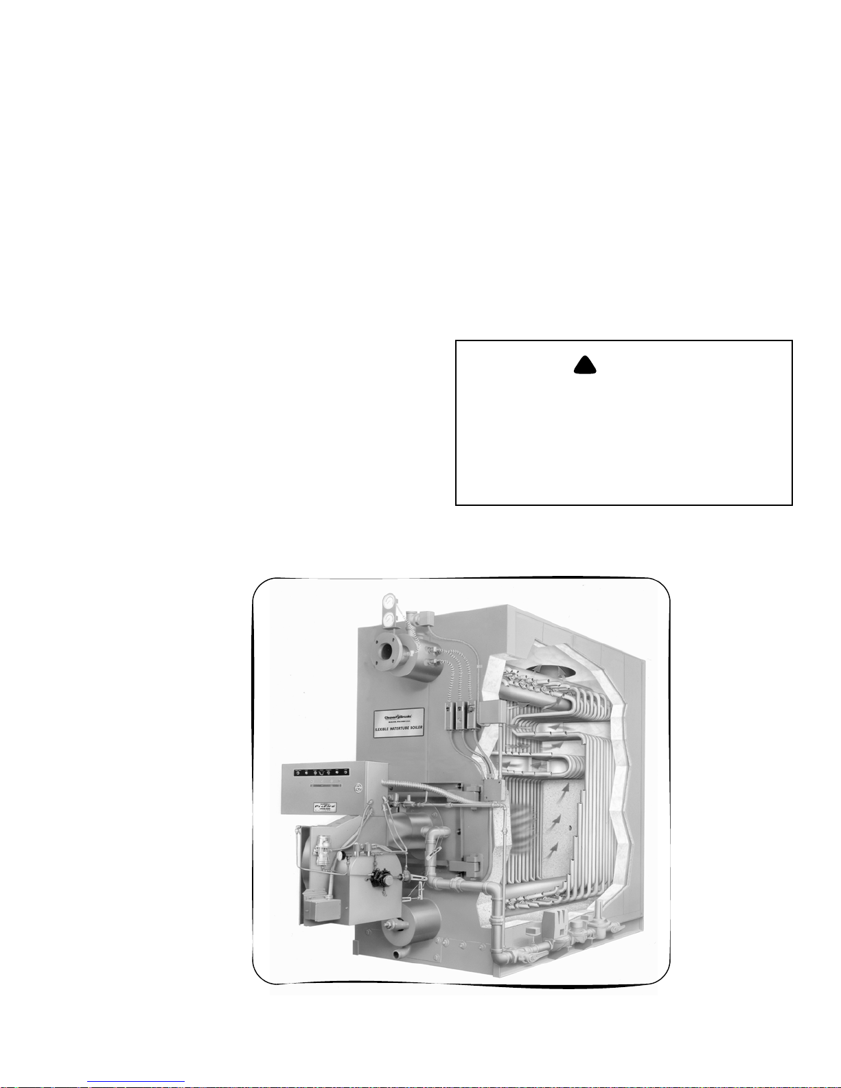
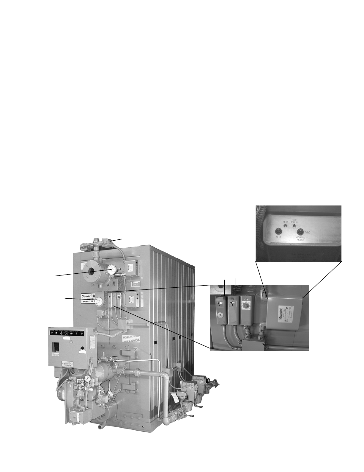
Figure 1-1: FLX Cut Away
Page 8

Chapter 1 GENERAL DESCRIPTION
B. The Boiler
The Cleaver-Brooks Model FLX is a five-pass steel boiler
with flexible watertubes formed and arranged so as to direct
the flow of combustion gases through the boiler. The pressure
vessel conforms to Section I or IV of the ASME code. The
pressure vessel consists of the formed tubes, the external
downcomer, and the top and bottom drums to which they
connect. The heated area of the pressure vessel is contained
within a gas tight insulated casing that is composed of
removable formed steel panels.
Always order genuine Cleaver-Brooks parts from your
local Cleaver-Brooks authorized representative.
The boiler and related equipment installation are to be in
compliance with the standards of the National Board of Fire
Underwriters. Installation should also conform to state and
local codes governing such equipment. Prior to installation,
the proper authorities having jurisdiction are to be consulted,
permits obtained, etc. All boilers in the above series comply,
when equipped with optional equipment, to Industrial Risk
Insurers (IRI), Factory Mutual (FM), or other insuring
underwriters requirements.
The Model FLX boiler is a packaged watertube boiler of
welded steel construction and consists of a pressure vessel,
burner, burner controls, forced draft fan, damper, refractory,
and appropriate boiler trim.
The type of service that your boiler is required to provide has
an important bearing on the amount of waterside care it will
require.
!
CAUTION
DANGER
Waterside care is of prime importance. For
specific information or assistance with your
water treatment requirements, contact your
Cleaver-Brooks service and parts representative. Failure to follow these instructions
could result in equipment damage.
Feedwater equipment should be checked and ready for use.
Be sure that all valves, piping, boiler feed pumps, and
receivers are installed in accordance with prevailing codes
and practices.
Water requirements for both steam and hot water boilers are
essential to boiler life and length of service. Constant
attention to water requirements will pay dividends in the form
of longer life, less down-time, and prevention of costly
repairs. Care taken in placing the pressure vessel into initial
service is vital. The waterside of new boilers and new or
remodeled steam or hot water systems may contain oil, grease
or other foreign matter. A method of boiling out the vessel to
remove accumulations is described in Chapter 3.
The operator should be familiar with Chapter 3 before
attempting to place the unit into operation.
Hot water is commonly used in heating applications with the
boiler supplying water to the system at 180 °F to 220 °F. The
operating pressure for hot water heating systems usually is
30 psig to 125 psig.
Steam boilers are designed for low and high pressure applications. Low pressure boilers are limited to 15 psig design
pressure, and are typically used for heating applications.
High pressure boilers are limited to 150 psig design pressure,
and are typically used for process steam applications.
Steam and hot water boilers are defined according to design
pressure and operating pressure. Design pressure is the maximum pressure used in the design of the boiler for the purpose of calculating the minimum permissible thickness or
physical characteristics of the pressure vessel parts of the
boiler. Typically, the safety valves are set at or below design
pressure. Operating pressure is the pressure of the boiler at
which it normally operates. The operating pressure usually is
maintained at a suitable level below the setting of the pressure relieving valve(s) to prevent their frequent opening during normal operation.
C. Construction
Steam boilers designed for 15 psig and hot water boilers
designed for 250°F at 160 psi or less are constructed in
accordance with Section IV, Heating Boilers, of ASME Code.
Steam boilers designed for 150 psig are constructed in
accordance with Section I, Power Boilers, of the ASME
Code.
D. Steam Controls (All Fuels)
1. Operating Limit Pressure Control (Figures 1-2 and 1-3):
Breaks a circuit to stop burner operation on a rise of
boiler pressure at a selected setting. It is adjusted to stop
or start the burner at a preselected pressure setting.
2. High Limit Pressure Control (Figure 1-2 and 1-3):
Breaks a circuit to stop burner operation on a rise of
pressure above a selected setting. It is adjusted to stop the
burner at a preselected pressure above the operating limit
control setting. The high limit pressure control is
equipped with a manual reset.
1-2 750-177
Page 9
GENERAL DESCRIPTION Chapter 1
3. Modulating Limit Pressure Control (Figure 1-2 and 1-3):
Senses changing boiler pressures and transmits the
information to the modulating motor to change the
burner firing rate when the manual-automatic switch is
set on “automatic.”
4. Low Water Cutoff and Pump Control (Figure 1-2, 1-4
and 1-5): Float-operated control responds to the water
level in the boiler. It performs two distinct functions:
•Stops firing of the burner if water level lowers below the
safe operating point. Energizes the low-water light in the
control panel; also causes low-water alarm bell (optional
equipment) to ring. Code requirements of some models
require a manual reset type of low-water cutoff.
•Starts and stops the feedwater pump (if used) to maintain
water at the proper operating level.
!
CAUTION
DANGER
Determine that the main and auxiliary low
water cutoffs and pump control are level after installation and throughout the equipment’s operating life. Failure to f ollow these
instructions could result in equipment damage.
5. Water Column Assembly (Figure 1-2): Houses the lowwater cutoff and pump control and includes the water
gauge glass, gauge glass shutoff cocks.
6. Water Column Drain Valve (Figure 1-2): Provided so
that the water column and its piping can be flushed
regularly to assist in maintaining cross-connecting
piping and in keeping the float bowl clean and free of
sediment. A similar drain valve is furnished with
auxiliary low-water cutoff for the same purpose.
7. Gauge Glass Drain Valve (Figure 1-2): Provided to flush
the gauge glass.
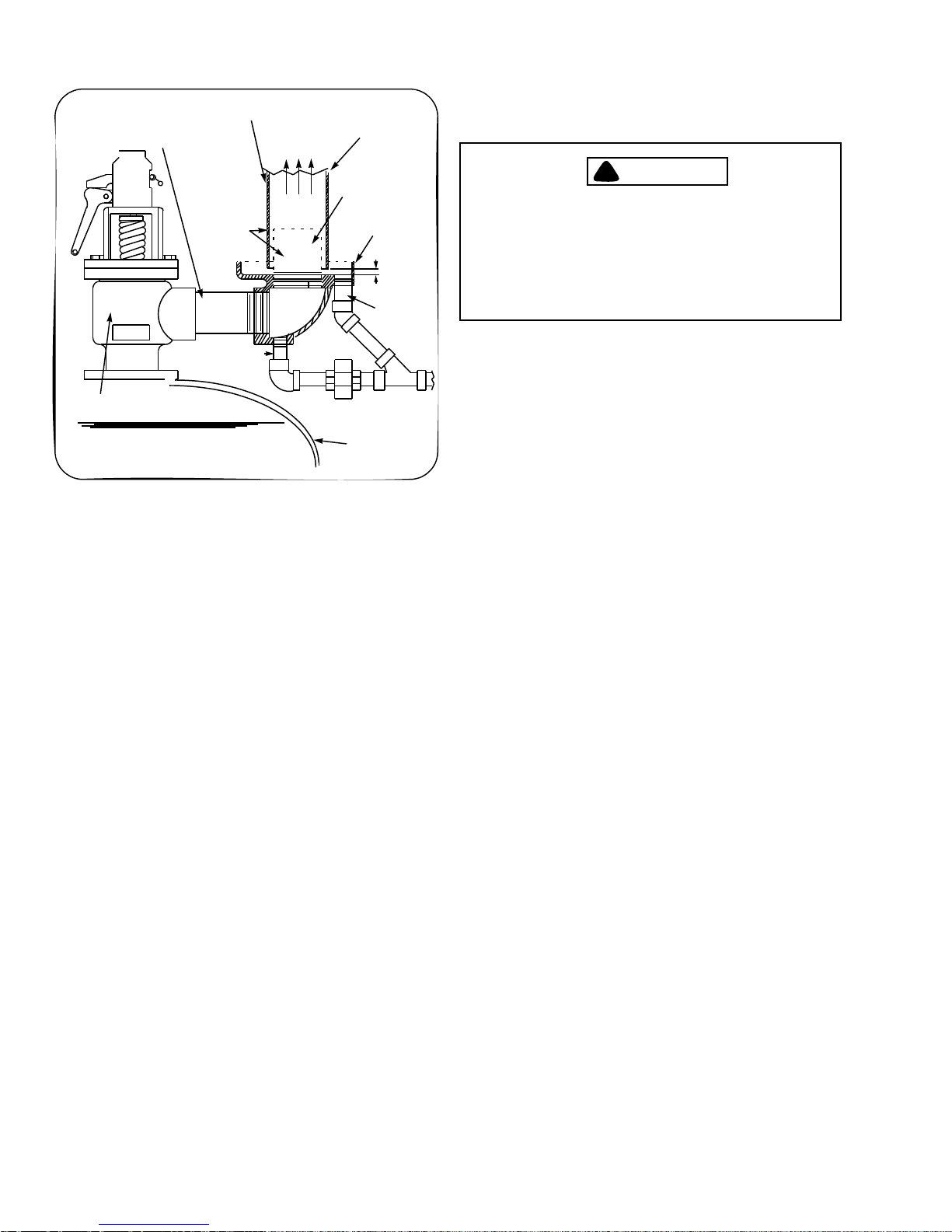
8. Safety Valve(s) (Figure 1-6 and 1-8): Prevent buildup
over the design pressure of the pressure vessel. The size,
rating and number of valves on a boiler is determined by
the ASME Boiler Code. The safety valves and the
discharge piping are to be installed to conform to the
ASME code requirements. The installation of a valve is
of primary importance to its service life. A valve must be
mounted in a vertical position so that discharge piping
and code-required drains can be properly piped to
prevent buildup of back pressure and accumulation of
foreign material around the valve seat area. Apply only a
moderate amount of pipe compound to male threads and
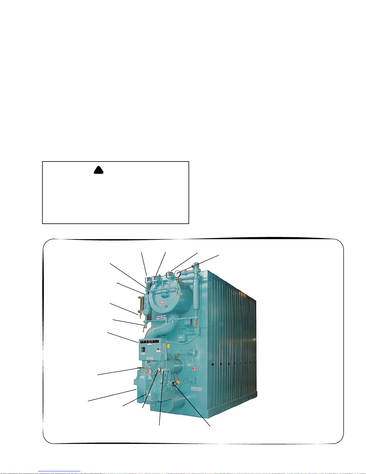
WATER COLUM N
LOW WATER CUTOFF
AND PUMP CONTROL
CONTROL PANEL
FLAME
DETECTOR
FORCED DRAFT
FAN MOTOR
GAUGE GLASS
DRAIN VALVE
WATER COLUMN
DRAIN VALVE
MODULATING
MOTOR
HIGH LIMIT
PRESSURE
OIL SUPPLY
PRESSURE
GAUGE
OPERATING LIMIT
PRESSURE
CONTROL
MODULATING LIMIT
PRESSURE
CONTROLCONTROL
STEAM PRESSURE
GAUGE
750-177 1-3
OIL SOLENOID
VALV ES
OIL PUMP
Figure 1-2: Typical Steam Boiler - Light Oil Fired
Page 10
Chapter 1 GENERAL DESCRIPTION
avoid overtightening, which can distort the seats. Use
only flat-jawed wrenches on the flats provided. When
installing a flange-connected valve, use a new gasket and
12
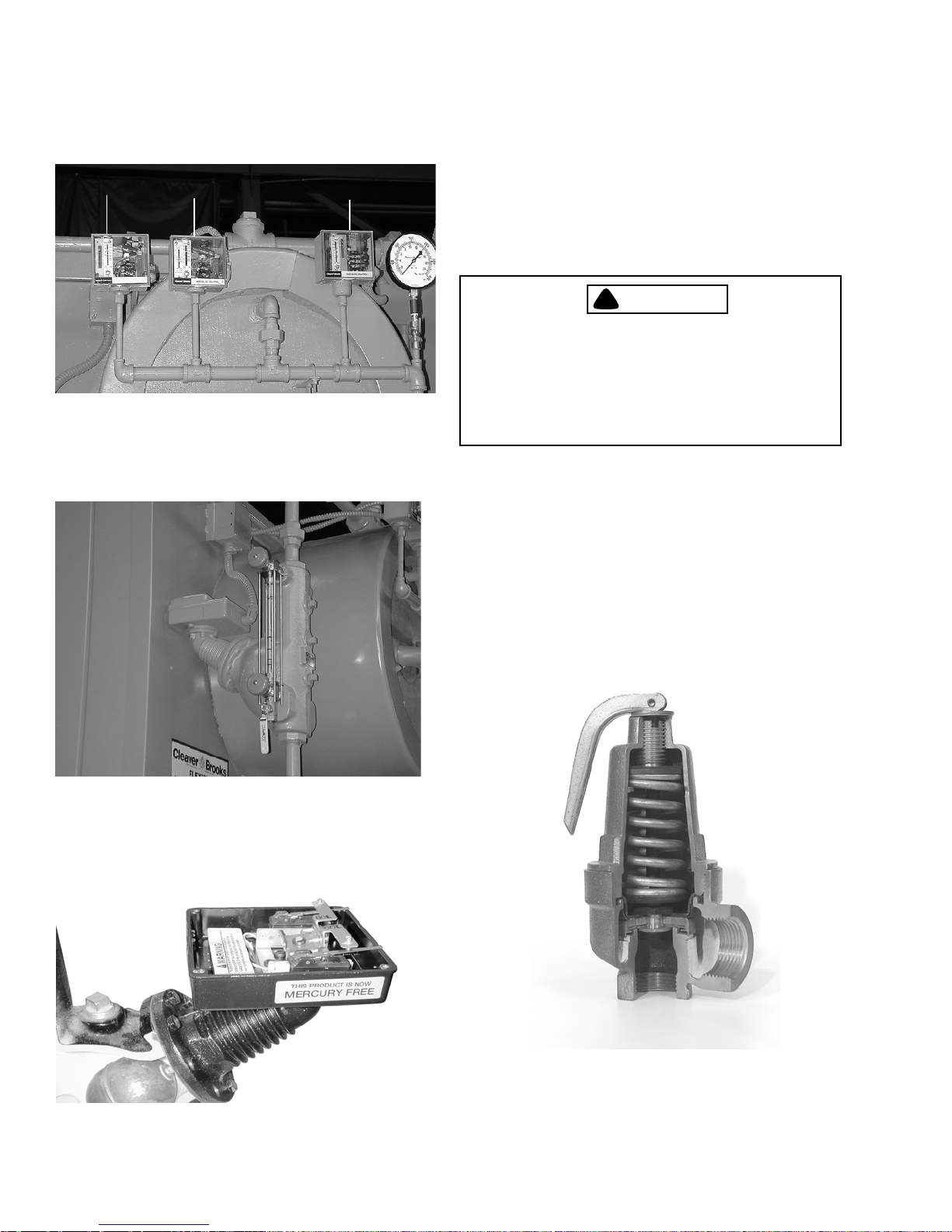
1. HIGH LIMIT PRESSURE CONTROL
2. OPERATING LIMIT PRESSURE CONTROL
3. MODULATING PRESSURE CONTROL
Figure 1-3: Steam Controls
3
draw the mounting bolts down evenly. Do not install or
remove side outlet valves by using a pipe or wrench in
the outlet.
!
WARNING
DANGER
Only properly certified personnel such as
the safety valve manufacturer’s certified
representative can adjust or repair the
boiler safety valves. Failure to follow these
instructions could result in serious
personal injury or death
E. Hot Water Controls (All Fuels)
Figure 1-4: Low Water Cut Off (LWCO)
1. Water Temperature Gauge (Figure 1-7): Indicates the
boiler internal water pressure.
2. Water Pressure Gauge (Figure 1-7): Indicates the internal
pressure of the boiler.
3. Operating Limit Temperature Control (Figure 1-7):
Breaks a circuit to stop burner operation on a rise of
boiler temperature at a selected setting. It is adjusted to
Figure 1-5: Low Water Cut Off Pump Control
(Cutaway)
1-4 750-177
Figure 1-6: Safety Valve Cutaway
Page 11
GENERAL DESCRIPTION Chapter 1
stop or start the burner at a preselected operating
temperature.
4. High Limit Temperature Control (Figure 1-7): Breaks a
circuit to stop burner operation on a rise of temperature
at a selected setting. It is adjusted to stop burner at a
preselected temperature above the operating control
setting. The high limit temperature control is equipped
with a manual reset.
5. Modulating Temperature Control (Figure 1-7): Senses
changing boiler water temperature and transmits the
information to the modulating motor to change the
burner firing rate when the manual-automatic switch is
set on “automatic.”
6. Low Water Cutoff (Figure 1-7): Breaks the circuit to stop
burner operation if the water level in the boiler drops
below safe operating point, activating low-water light
and optional alarm bell if burner is so equipped.
7. Auxiliary Low Water Cutoff (Not Shown) (Optional):
Breaks the circuit to stop burner operation if the water
level in the boiler drops below the master low-water
cutoff point.
8. Safety Valve(s) (Figure 1-6 and 1-8): Prevent buildup
over the design pressure of the pressure vessel. The size,
rating and number of valves on a boiler is determined by
the ASME Boiler Code. The safety valves and the
discharge piping are to be installed to conform to the
ASME code requirements. The installation of a valve is
of primary importance to its service life. A valve must be
mounted in a vertical position so that discharge piping
and code-required drains can be properly piped to
prevent buildup of back pressure and accumulation of
foreign material around the valve seat area. Apply only a
moderate amount of pipe compound to male threads and
avoid overtightening, which can distort the seats. Use
only flat-jawed wrenches on the flats provided. When
installing a flange-connected valve, use a new gasket and
draw the mounting bolts down evenly. Do not install or
WATER
PRESSURE
GAUGE
WATER
TEMPERATURE
GAUGE
LOW WATER CUTOFF PROBE
23
1
1. High Limit Temperature Control
2. Operating Limit Temperature Control
3. Modulating Temperature Control
4. Low Water Cutoff Control
4
750-177 1-5
Figure 1-7: Hot Water Controls
Page 12
Chapter 1 GENERAL DESCRIPTION
SUPPORT FROM BUILDING
DISCHARGE OPENING MUST BE
EQUAL TO OR LARGER THAN
INLET
DRIP ELL DRAIN
SAFETY VALVE
NOTICE: BACK-PRESSURE OF STEAM
EXHAUST SYSTEM MUST BE LESS THAN 6%
OF SAFETY VALVE SETTING.
WATER LEVEL
CONSTRUCTION
CAUTION VENT PIPE
MUST NOT
TOUCH DRIP
PAN EXTENSION
TO STEAM
VENT
VENT PIPE
DRIP PAN
EXTENSION
AND ELBOW
OPEN DRAIN
TO WASTE
BOILER SHELL
Figure 1-8: Recommended Piping For Steam
Relief Valve (Not furnished by Cleaver-Brooks)
DRIP PAN
1 1/2”
MIN.
DRIP PAN
DRAIN
remove side outlet valves by using a pipe or wrench in
the outlet.
!
WARNING
DANGER
Only properly certified personnel such as
the relief valve manufacturer’s certified
representative can adjust or repair the
boiler relief valves. Failure to follow these
instructions could result in serious
personal injury or death.
1-6 750-177
Page 13

CHAPTER 2
Profire V Burner
A. Introduction . . . . . . . . . . . . . . . . . . . . . . . . . . . . . . .2-1
B. Installation . . . . . . . . . . . . . . . . . . . . . . . . . . . . . . . .2-5
C. Startup and Operation . . . . . . . . . . . . . . . . . . . . . . .2-17
D. Adjustments . . . . . . . . . . . . . . . . . . . . . . . . . . . . . .2-22
E. Maintenance . . . . . . . . . . . . . . . . . . . . . . . . . . . . . .2-31
F. Troubleshooting . . . . . . . . . . . . . . . . . . . . . . . . . . .2-35
G. Burner Specs . . . . . . . . . . . . . . . . . . . . . . . . . . . . . .2-39
A. Introduction
CB Profire V/Series burners are assembled, wired, and tested
at the factory. The V/Series burner line is listed by the
Underwriters Laboratory for the U.S. and Canada, and bears
the UL and cUL markings when ordered as such by the
customer. Compliance with other regulatory agencies such as
CSD-1, I.R.I./GE GAP, F.M., etc., is available at time of
order.
Optional controls and control systems are also available. The
operator of this equipment must be familiar with the
individual functioning of all controls to understand the
operations and procedures described in this manual, and
supplementary instructions provided with optional controls.
Identify and locate each item in the illustrations as they are
described in the following sections.
The burners are available in the following configurations:
SIZE 1 - V13-34 - On-Off (Optional: Low-High-Off, LowHigh-Low, Full Modulation)
SIZE 2 - V35-55 - Low-High-Off (Optional: Low-High-Low,
Full Modulation)
SIZE3 - V60-63 - Low-High-Off (Optional: Low-High-Low,
Full Modulation)
SIZE 3 & 4 - V70-168 - Full Modulation
OPERATING CONTROLS - PANEL
The burner control panel may be integral to the burner or
remote, and contains a flame safeguard programming control,
motor relays (starters), and terminal strips mounted internally
on a panel subbase. Lights, switches, and a control circuit
breaker are mounted externally on the panel.
1. ON-OFF BURNER SWITCH
2. FUEL SELECTOR SWITCH - Gas-Off-Oil
Gas position: Selects gas as the firing fuel
Off position: Burner off
Oil position: Selects oil as the firing fuel
3. CONTROL CIRCUIT BREAKER
Supplementary low overcurrent protection only. No
larger than 15 amps.
!
CAUTION
DANGER
ONLY FACTORY AUTHORIZED BURNER SERVICE PERSONNEL SHOULD START UP, ADJUST,
OR SERVICE THIS EQUIPMENT.
DESCRIPTION
The CB Profire V/Series burners are designed to operate with
natural gas and light oil. The burners are designed for
automatic, unattended operation except for periodic
inspection and maintenance. The control panel components
require little attention except for occasional cleaning.
750-177 2-1
4. AUTO-MANUAL MODULATION SELECTOR
SWITCH
Auto position: Selects boiler modulation control. In this
position, the burner will operate automatically in
response to load demand.
Manual position: Selects 135 ohm potentiometer for
manual modulating control.
5. MANUAL MODULATING CONTROL - 135 ohm
(For full modulation burner only.) Increases or
decreases the burner firing rate.
6. SIGNAL LAMPS
a. POWER ON (white) - Illuminates when the control
circuit is energized (powered).
b. IGNITION (amber) - Illuminates when the ignition
2-1
Page 14

Chapter 2 Profire V Burner
transformer is powered, and pilot valve is energized
(open).
c. MAIN FUEL (green) - Illuminates when the main
fuel valve or valves are energized (open).
d. FLAME FAILURE (red) - Illuminates when the
flame safeguard system fails to detect pilot or main
flame.
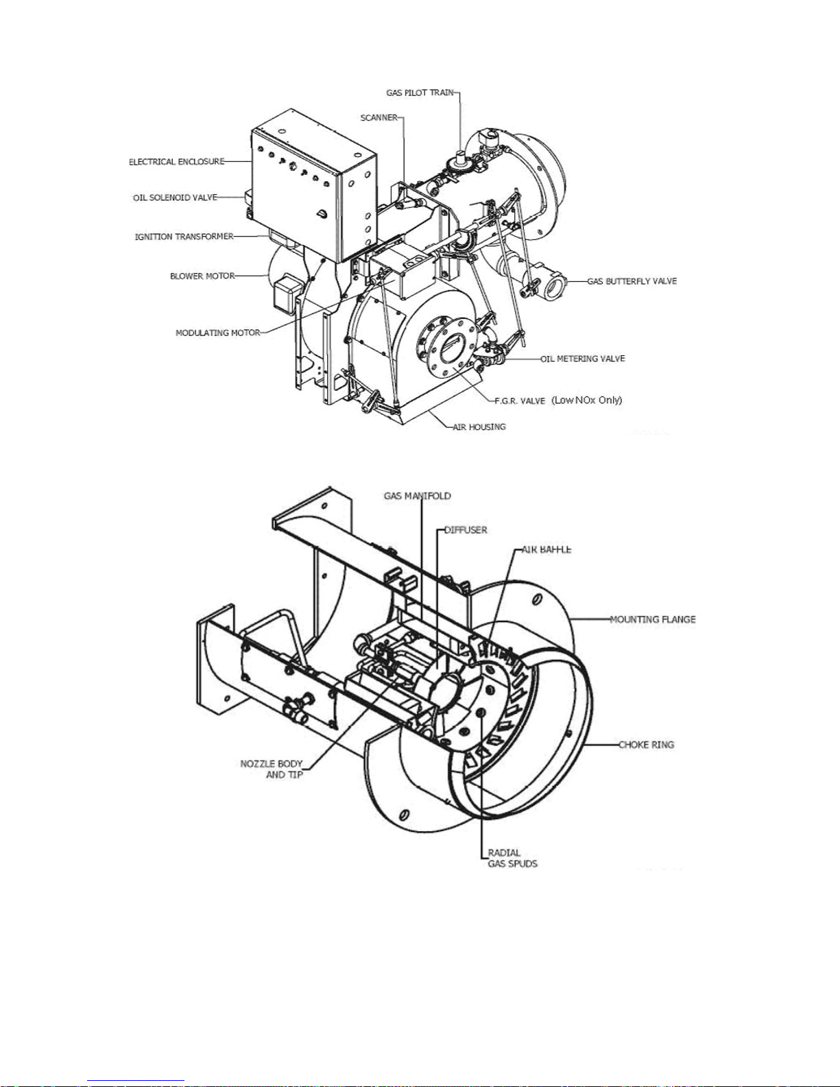
7. MODULATING MOTOR
Operates the air damper and fuel rate valves through a
linkage system to adjust air-fuel ratios under all load
conditions.
8. IGNITION TRANSFORMER
Provides high voltage spark for ignition of gas pilot or
main flame direct spark models.
FLAME SAFEGUARD CONTROLS
The flame safeguard controls the operating sequence of the
combustion system (pre-purge, pilot, firing, and shutdown).
The flame safeguard programmer incorporates a flame
sensing cell (scanner) to shut down the burner in the event of
pilot flame or main flame failure. Other safety controls shut
down the burner based on sequence of operation as shown in
the manufacturer’s flame safeguard manual.
When a parallel positioning system is furnished, the flame
safeguard may be incorporated as an integral component to
the parallel positioning control. Consult burner and
component technical documentation.
air flow with the fuel flow provides efficient combustion at all
firing rates.
OIL SYSTEM
Models Vl-VLG are high pressure atomizing burners using
fuel pressure for atomization. Atomized fuel is discharged
from the nozzle as a fine conical spray.
1. FUEL UNIT - Size 1 & 2
Direct driven from the blower motor with a flexible coupling
at 3450 rpm, and set for 300 psi operation, fuel unit is two
stage (two sets of gears) and must be installed for a two pipe
installation, one suction and one return line. Separately
driven oil pumps are available as options to the standard
arrangement.
Size 3 & 4
A separately driven oil pump is standard.
2. NOZZLE
The nozzle meters oil flow delivering a specified amount at a
specific pressure. Fuel pressure (mechanical) atomizes oil in
a fine conical spray pattern from the nozzle orifice. The
ABC
burner is supplied with nozzle(s) to fire to its maximum rate
unless a different firing rate was specified. VL and VLG
models 13-34 supplied with simplex nozzles, models 35-168
are supplied with return flow nozzles.
3. NOZZLE ADAPTOR
D
EFG
COMBUSTION AIR HANDLING SYSTEM
1. MOTOR AND BLOWER
The impeller is directly driven by the motor at 3450 rpm. A
heavy duty forward curved, multi-blade centrifugal impeller
supplies combustion air.
2. AIR VOLUME REGULATOR
Air dampers are located in the air inlet housing. The dampers
are mechanically linked and actuated by a two-position motor
or hydraulic cylinder for on-off operation. Low-high-off,
low-high-low, or full modulation burners have the dampers
mechanically linked to the modulating motor.
3. COMBUSTION AIR PROVING SWITCH
A pressure sensitive, differential switch actuated by air
pressure created by the blower fan. Contacts close to prove
combustion air flow.
4. DIFFUSER
An air flow diffuser stabilizes flame front.
OPERATION: Air from the impeller flows through the blast
tube and diffuser to mix with fuel in the ignition zone.
Combustion air flow rate is determined by the position of the
air regulating blades at the inlet of the impeller. Linking the
The nozzle adaptor provides the means for connecting fuel
lines with the nozzle.
4. OIL SOLENOID VALVES
Two normally closed (N.C.) and one normally open (N.O.)
solenoid valves are part of the oil system on LO-HI-OFF and
8
LO-HI-LO burners. The two N.C. valves provide positive
shutoff of fuel oil while the one N.O. valve cycles the burner
to HI fire when closed.
5. OIL METERING VALVE
The firing rate is controlled by an adjustable metering valve
in the return line. At low fire, the metering valve is open, and
is closed at high fire.
6. OIL FILTER
Prevents foreign matter from entering the burner oil system.
This item is provided optional and shipped loose with burner.
OPERATION: Fuel oil is delivered to the fuel unit, either by
gravity, fuel unit suction, or by a circulating pump, through a
fuel oil filter. Pressurized fuel returns to the storage tank until
the two solenoid valves open. On direct spark ignited burners
(VL-13 to 55) ignition occurs when the oil valves open.
Where gas pilots are provided (models VG and VLG), the oil
valves open after the pilot is proven. Oil input rate is
controlled by the oil metering valve, which varies the flow to
2-2 750-177
Page 15

Profire V Burner Chapter 2
meet load demands. The low fire positions bypass oil back to
the storage tank. At high fire, the metering valve is in the
closed position. The modulating motor positions the metering
valve and the air damper simultaneously.
IGNITION SYSTEM
Oil only models VL-13 to 55 are supplied with direct spark
ignition. Models VL-60 to 168 are supplied with a gas pilot
system. Gas and combination gas-oil models are supplied
with a gas ignition system. The standard pilot gas train
consists of a manual shutoff cock, a gas pressure regulator,
and a solenoid operated gas shutoff valve.
GAS HANDLING SYSTEM
Depending upon the requirements of the regulating authority,
the gas control system and gas train may consist of some, or
all, of the following items:
1. GAS VOLUME VALVE
The butterfly type valve is positioned by linkage from the
modulating motor and control the rate of flow of gas.
2. MAIN GAS VALVES
Electrically operated safety shutoff valve(s) that open to
admit gas to the burner. Standard U.L. burners include:
A pressure actuated switch that remains closed when gas
pressure is above a selected setting. Should the pressure drop
below this setting, the switch contacts will open, causing
main gas valve(s) to close. This switch requires manual reset
after being tripped.
OPERATION: Metered gas flows through the main gas
shutoff cock, through the pressure regulators to the automatic
gas valves and butterfly valve to the gas manifold. The
butterfly gas valve modulates flow to burner input demand.
The butterfly valve is positioned through mechanical linkage
by the modulating motor. The air control damper is
positioned simultaneously by the modulating motor. The
automatic gas valve(s) cannot be energized unless the
combustion air proving switch is closed. The low and high
gas pressure switches must be closed to prove proper gas
pressure.
A normally open vent valve, if required, is located between
the two automatic gas valves. This valve is shut when the
automatic gas valves are open. When the automatic valves are
closed, the vent valve is open for venting gas to the outside,
should any be present.
A
B
Notice: Gas train components upstream of the
butterfly valve are shipped loose to be mounted by
the installer.
• Models 13-25: Diaphragm gas valve & solenoid valve.
• Models 30-50: One motorized gas valve w/proof of closure or two safety shutoff valves.
• Models 55-120: One motorized gas valve w/proof of
closure and one safety shutoff valve.
• Models 126-168: Two motorized gas valves.
(Two motorized gas valves can be optionally provided on all
models.)
3. MAIN GAS REGULATOR
Regulates gas train pressure to specified pressure required at
the burner manifold. Input is set by main gas pressure
regulator adjustment.
4. MAIN GAS COCKS
Used for manual shutoff of the gas supply upstream of the
pressure regulator. A second shutoff cock downstream of the
main gas valve(s) provides a means of testing for leakage
through the gas valve(s).
5. HIGH GAS PRESSURE SWITCH (Models 30-168)
A pressure actuated switch that remains closed when gas
pressure is below a selected setting. Should the pressure rise
above the setting, the switch contacts will open causing main
gas valve(s) to close. This switch requires manual reset after
being tripped.
Notice: Pilot gas supply connection must be
upstream of the main gas pressure regulator.
6. LOW GAS PRESSURE SWITCH (Models 30-168)
750-177 2-3
Page 16
Chapter 2 Profire V Burner
Figure 2-1: Profire Burner
Figure 2-2: Interior Burner Components
Figure 2-2: Burner-Cutaway View
2-4 750-177
Page 17
Profire V Burner Chapter 2
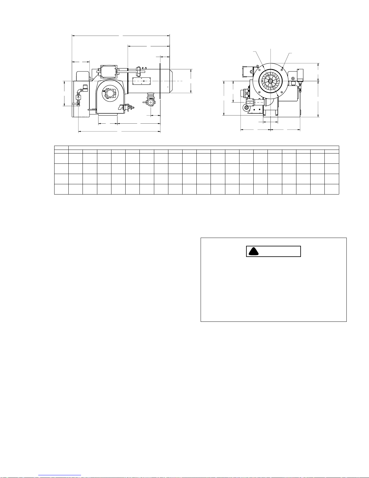
A
J
I
G
H
BURNER
MODEL A B C D E F
SIZE 1
SIZE 2
SIZE 3
SIZE 4
32 7/8 12 3/8
37 1/3 13 5/8
44 3/8 16 1/8
54 3/8 24 7/8
8 1/4 3 3/4
4
4104
11 1/2 3 3/4 17 1/2 15 3/4 41 3/4 15 1/4 7 3/8 16 3/4 15 1/4 8 3/8 17 3/8 12 1/2 14 1/8 6 1/4 10 1/4 18 5/8
4
13 5/8
5
B. Installation
B
K DIA.
C
D
C
L
T
U
E
F
STANDARD CONFIGURATION - REAR MOUNTED PANEL, GAS PILOT LINE PANEL MOUNTED
18 1/8
25 1/4
4
G
H I
9 3/4
15
30
34 1/2 10 1/2 7 3/8
8
45 7/8 13 1/2 7 3/8 17 1/2 15 3/8 8 3/4 20 1/8 14 1/2
12
J
K L M N P R S T
9 3/4 7 3/8 12 7/8 11 1/4 6 1/2 14 3/8
13 1/4 7 1/2 15 1/8 12 1/2 12 3/4 6 1/4
15
S
Figure 2-3: Burner Dimensions (Inches)
Consult with insurance carrier and/or local authorities for
specific regulations.
C
L
4X Ø3/4
L B.C.
M
C
L
N
PR
656-00037
U
13
5 /14 7 1/4 11 3/4
12
7 1/2 12 1/4 19 1/4
16
14 1/2
9
DRAFT CONDITIONS
A boiler or other heating vessel fired with a V Series burner
does not depend on chimney draft for proper combustion air.
Combustion air is supplied by the burner forced draft blower
providing adequate air for any normal combustion condition.
Since draft control is essential to maximum efficiency, a draft
regulator may be required when the vessel is connected to a
tall stack or where wind conditions may cause erratic draft.
Excessive furnace draft contributes to inefficient burner
operation.
Sealed boilers may be operated under positive firebox
pressure within the capability of the burner.
COMBUSTION AIR SUPPLY
The space in which a burner operates must be supplied with
adequate fresh air for combustion and ventilation purposes.
Fresh air supply must meet or exceed all code requirements.
!
WARNING
DANGER
!
CAUTION
DANGER
THE BOILER ROOM PRESSURE MUST BE AT
LEAST EQUAL TO THE OUTDOOR A TMOSHERIC
PRESSURE. WHERE FAN VENTILATION IS
USED, AIR MUST BE FORCED INTO THE BOILER
ROOM. NEVER EXHAUST AIR FROM THE
BOILER ROOM. ADJOINING AREAS HAVING
EXHAUST FANS MUST BE POSITIVELY ISOLATED FROM THE BOILER ROOM.
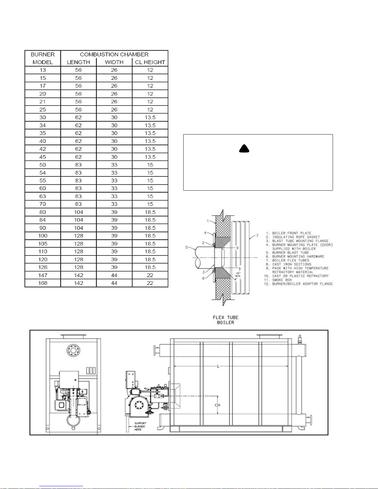
COMBUSTION CHAMBER DESIGN
The V series burners are of the forced draft flame retention
type. Refractory is required only to protect surfaces not
adequately protected by free circulating water. Four basic
objectives are:
• Provide adequate combustion space
• Avoid flame impingement
• Protect surfaces not adequately water cooled
• Seal openings
The table below shows suggested minimum combustion
chamber dimensions.
750-177 2-5
Page 18
Chapter 2 Profire V Burner
Suggested Minimum Combustion Chamber Dimensions
While these dimensions are typical for good practice,
satisfactory results may be achieved with modifications to
suit some conditions. Factors such as fuel properties, total
combustion volume, length of flame trave often make fixed
requirements impractical. When in doubt, consult the factory.
Insulation should be provided between the refractory and the
boiler base. Mineral wool, or other material not likely to settle
is preferred. The chamber front wall may be constructed of
firebrick or insulating firebrick. Insulation should be used
between refractory and front plate. Firebrick, or insulating
firebrick should be set in high temperature bonding mortar
with provision for expansion.
!
CAUTION
DANGER
THE GASKET MUST BE RESILIENT TO SEAL
ANY UNEVEN AREAS BETWEEN THE BURNER
FLANGE AND THE BOILER FRONT PLATE TO
PREVENT LEAKAGE OF COMBUSTION GASSES.
Suggested Minimum Combustion Chamber Dimensions are
based on the rated capacity of the burner.
Figure 2-7: V Burner Installation, Commercial Watertube Boiler
2-6 750-177
Page 19

Profire V Burner Chapter 2
GAS PIPING
Gas service and house piping must supply the quantity of gas
demanded by the unit at the pressure required at the burner
gas train inlet.
All piping must be in strict accordance with applicable codes,
ordinances and regulations of the supplying utility. In the
absence of other codes, piping should be in accordance with
the following standards: “National fuel Gas Code” NFPA No.
54, ANSI No. Z223-1.
Gas train components upstream of the butterfly valve are
shipped loose. These components should be mounted by the
installer as close to the butterfly valve as practical.
Normally, the control train is ordered to suit a particular code
or insurance regulation - such as Underwriters Laboratories/
Canadian Underwriters Laboratories (UL/cUL), Factory
Mutual, or Industrial Risk Insurance.
Arrange gas piping at the burner so that the burner is
accessible for servicing without disassembly.
The pilot gas train is supplied with the burner, and is factory
installed. The gas pilot supply line must be connected
upstream of the main gas regulator. If a reducing bushing is
required between the house piping and the burner piping, it
should be close to the burner shutoff valve.
The gas piping must be internally clean and free of foreign
material. Before using in service, a leak test must be
performed.
FUEL OIL PIPING
PRESSURE ATOMIZATION OIL PIPING
The VL and VLG model burners use pressure atomization.
Fuel oil is provided by a burner mounted fuel unit directly
coupled to the blower motor via a flexible coupling on Size 1
& 2 burners, Remote Pump on Size 3 & 4 burners. The
suction and return line sizes (two-pipe system) are based on
the suction rate of the fuel unit and not the burner firing rate.
Pipe size must be selected sot that suction vacuum is within
suitable limits.
TWO PIPE - SINGLE BURNER OPERATION
A two-pipe system is essential. The suction and return
between the storage tank or supply source and the burner
must be sized to supply the required quantity of oil circulated,
including excess oil returned to the storage tank.
SUCTION LINE SIZING
The Suction load is determined by:
1. The vertical lift from the oil level in the tank to the
pump.
2. Pressure drop through valves, fittings, strainers, etc.
a. Quantity of oil pumped (gph).
b. Length of suction line (feet).
c. Diameter of the suction line.
d. Number of fittings.
Although the gear type pumps used on the V series burners
are capable of developing higher suction, it is not desirable to
operate above 15 inches of mercury vacuum. If the vacuum is
greater, flow may be erratic.
Refer to the manufacturer’s table for line sizing.
1. Check suction capacity.
2. Measure total pipe length (horizontal and vertical).
3. Read up from line “total feet of copper tube” to the
intersection line of the specific “suction capacity” in
gph.
4. Read left to column “inches of vacuum at fuel unit.”
This is vacuum required to draw oil through pipe listed
at given length.
5. Add 1” of vacuum for every foot of lift.
6. Total inches of vacuum (frictional tube loss plus lift).
7. If total exceeds 15”, check next larger pipe size.
RETURN LINE SIZING
Generally, the return line should be sized the same as the
suction line.
TWO PIPE - MULTIPLE BURNER SYSTEM
Several options exist for a multiple burner installation.
The circulating pump is sized for the total suction capacity of
all burners. Note that a special pressure regulating valve is
required if the fuel unit inlet pressure is above 3 psi.
Depending on configurations:
• separate suction lines for each burner with a common
return line
• multiple burners with oil supplied by a transfer pump
• a pump supplies oil to the day tank
• flooded loop system - the circulating pump is sized
according to the maximum burner firing rate for all
burners plus a 30% service factor
Notice: CB Profire recommends that all oil firing burners be equipped with an oil strainer (if
not included with the burner) to prevent particles from clogging the nozzle. It is essential to
follow the strainer manufacturer’s maintenance
schedule to ensure proper filtration.
3. The friction loss due to oil flow. This loss varies with:
750-177 2-7
Page 20
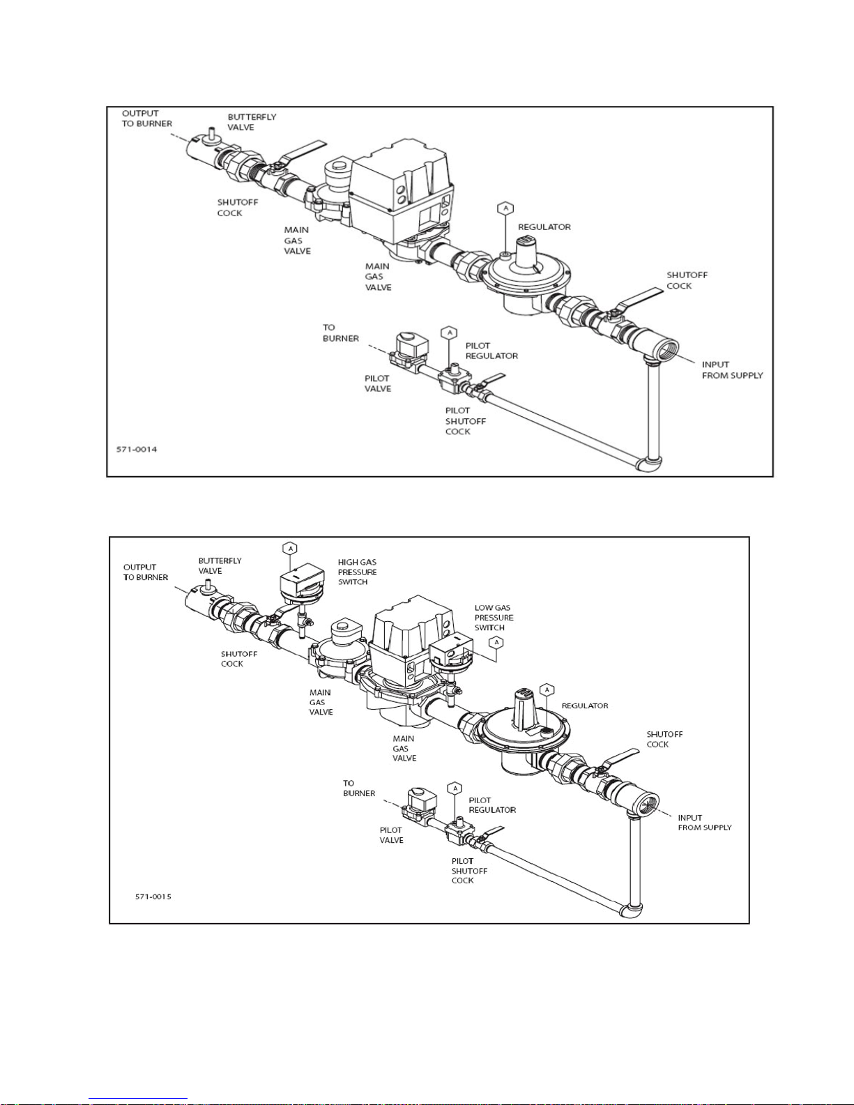
Chapter 2 Profire V Burner
Figure 2-11: Typical UL Gas Train, Full Modulation System, Size 1 V13 to V34
Figure 2-12: Typical UL Gas Train, Low-High-Off/Low-High-Low, Size 2 V35 to V63, Full Mod System, Size 2-3-4 V35 to V168
2-8 750-177
Page 21
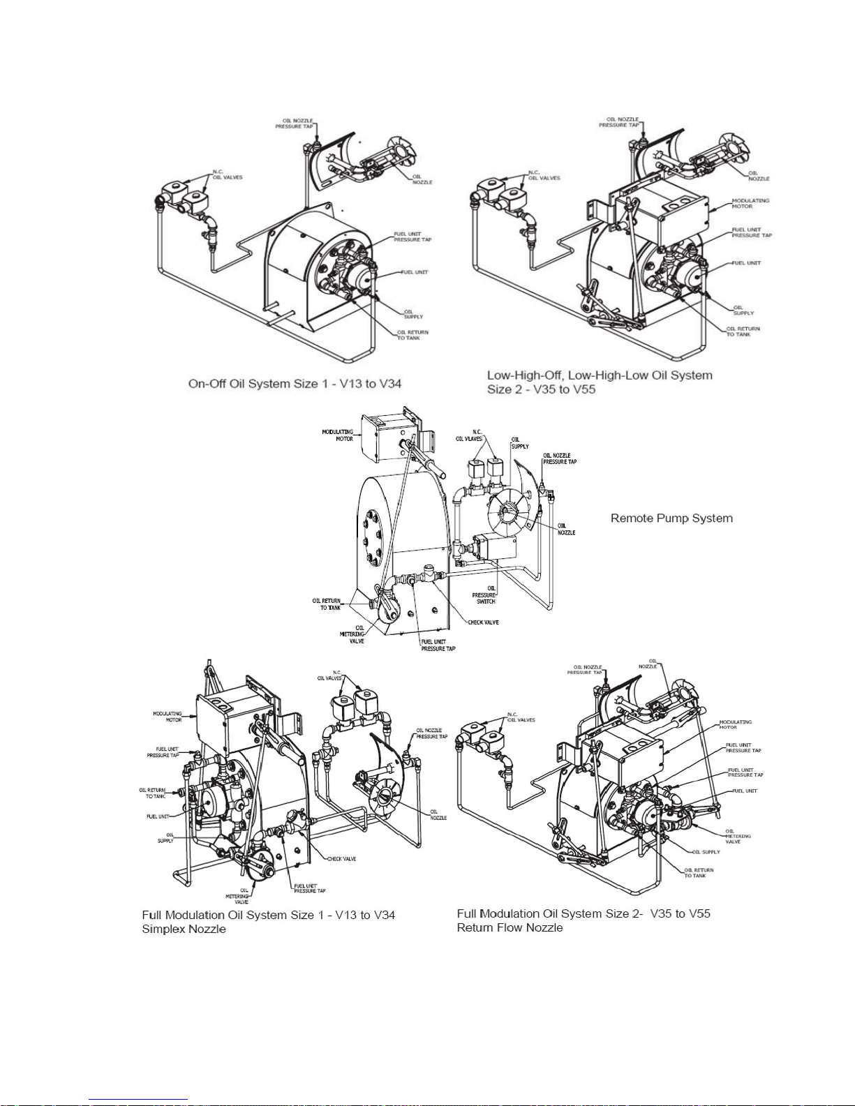
Profire V Burner Chapter 2
750-177 2-9
Figure 2-13: Oil System Configurations
Page 22
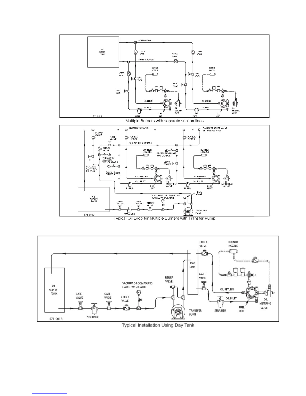
Chapter 2 Profire V Burner
Figure 2-14: Multiple Burners Configurations
Figure 2-15: Day Tank
2-10 750-177
Page 23

Profire V Burner Chapter 2
Figure 2-7: Typical Flooded Loop System
INSTALLATION CHECKLIST
1. All burners are carefully assembled and tested at the
factory, but before being placed in service all connectors
should again be checked for looseness caused during
shipment.
Check:
a. Electrical terminals in the control panel and on all
electrical components.
b. Pipe fittings and unions.
c. Tubing connections.
d. Nuts, bolts, screws.
2. Open all necessary oil shutoff valves. Do not run pumps
or fuel unit without oil.
3. Before connecting electrical current to any component,
be sure the voltage is the same as that specified on component nameplates.
4. Before burner operation, be sure all motors are rotating
in the proper direction.
5. Before firing, make sure the burner firing head and dry
areas of the boiler are protected with refractory. The
burner mounting flange must be properly sealed against
the vessel front plate.
!
CAUTION
DANGER
BEFORE OPENING THE MANUAL GAS SHUTOFF
VALVES, READ THE REGULATOR INSTRUCTIONS CAREFULL Y. THE INSTRUCTIONS ARE IN
THE REGULATOR BOX. FOLLOW THE MANUFACTURER RECOMMENDATIONS. OPEN SHUTOFF VALVE ON THE INLET SIDE OF THE
REGULATOR SLOWLY AND CAREFULLY TO
ALLOW INLET PRESSURE TO BUILD UP
SLOWL Y IN THE REGULATOR UNTIL IT IS FULL Y
PRESSURIZED. OPEJNING THE SHUTOFF
VALVE QUICKLY WILL DAMAGE THE REGULATOR. DO NOT EXCEED THE REGULATOR PRESSURE RA TINGS.
6. Make certain that the operator in charge is properly
instructed in operation and maintenance procedures.
750-177 2-11
Page 24

Chapter 2 Profire V Burner
FIRING MODES
Different modulation modes are available with the Profire V burner. The Model FLX will utilize one of the
following:
Low - High -Low (60% damper purge).
Low - High -Low (open damper purge).
Full Modulation (open damper purge).
See following pages for operating descriptions of each firing mode
.
2-12 750-177
Page 25
Profire V Burner Chapter 2
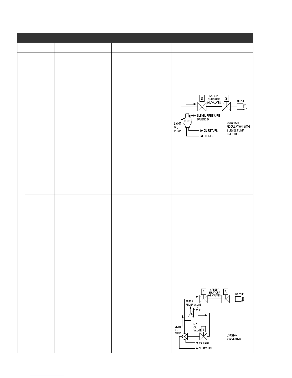
LOW-HIGH-LOW MOD - LOW or 60% DAMPER PURGE
Combustion Air Gas Oil
A two blade damper is
COMPONENTS
DESCRIPTION:
controlled by a two position,
spring return actuator with
mechanical linkage. For 60%
damper purge a mechanical
stop is provided on the damper
to ensure sufficient air flow is
provided during prepurge.
Power to drive the actuator is
routed through a low/auto
switch and a remote located
modulating control. The
actuator also contains a limit
switch which is used to actuate
the second stage of the oil
supply system. (see oil at right).
Safety shut off valve(s) are
provided to initiate the flow of gas.
The primary is a diaphragm or
motorized type valve which have
delayed opening rates to prevent
an "in rush" of gas. A butterfly
type gas metering valve is linked
directly to the damper actuator
and provides gas flow metering
during the drive to the high
position. A manually adjusted gas
regulator limits maximum firing
rate.
Pressure Atomization: Two solenoid type
safety shut off oil valves initiate the flow of oil
from the high pressure pump to the nozzle.
The oil pump has a built in solenoid controlled
two level pressure regulating system. Low and
high flow rates are set on the pump based on
pressure and the nozzle's flow
rating.
PRE-PURGE:
STARTUP,
IGNITION:
RUN,
MODULATE:
Operating Sequence
SHUT DOWN,
POST-PURGE:
Damper is in its closed or low
fire position. For 60% damper
purge this would be against the
mechanical stop.
Damper remains in its low fire
starting position.
Damper is driven open in 30
seconds by the two position
actuator. Low-High-Low
burners will modulate from the
low to high rate positions based
on the signal from the
modulating control and the
selection of the low/auto switch.
Damper returns to its start
position based on the 25
second closure speed of the
mechanical actuator.
Valves are closed.
Valves open. To prevent a surge
the primary gas valve opens at a
slowed rate. Gas flow to the
manifold is metered based on the
butterfly valves low fire setting.
The gas valves remain in their
open position. The actuator
begins it's travel to the high fire
position opening the gas metering
valve. The burner will then
modulate from low to high as
described in the combustion air
column.
On shut down all gas valves close
within 1 second. The butterfly
valve closes in 25 seconds with
the two position actuator.
The pump is operational but the valves are
closed. Oil is flowing through an internal relief
valve and returning to the supply system.
Safety shut off valves open allowing oil to flow
from pump to nozzle. Oil pressure at the nozzle
is based on the pump's low pressure setting.
Excess oil is flowing through an internal relief
valve and returning to the supply system.
The safety shut-off oil valves remain open. The
pump's solenoid is energized by the auxiliary
switch within the damper actuator as it opens
the air damper. Oil pressure is then increased
based the pumps high pressure setting. The
burner will then modulate from low to high as
described in the combustion air column.
All valves immediately return to their startup or
de-energized position. The oil pump is
operating with post-purge, but oil is flowing
through an internal relief valve and returning to
the supply system.
For pumps without the internal dual pressure
solenoid an external pressure relief valve and
normally open solenoid valve are
used.
VARIATIONS: None None
750-177 2-13
Page 26

Chapter 2 Profire V Burner
LOW-HIGH-LOW MOD - OPEN DAMPER PURGE
Combustion Air Gas Oil
Pressure Atomization: Two solenoid type safety
shut off oil valves initiate the flow of oil from the high
pressure pump to the nozzle. The oil pump has a
built in solenoid controlled two level pressure
regulating system. Low and high flow rates are set
on the pump based on pressure and the nozzle's
flow
rating.
The pump is operational but the valves are closed.
Oil is flowing through an internal relief valve and
returning to the supply system.
Safety shut off valves open allowing oil to flow from
pump to nozzle. Oil pressure at the nozzle is based
on the pump's low pressure setting. Excess oil is
flowing through an internal relief valve and returning
to the supply system.
The safety shut-off oil valves remain open. The
pump's solenoid is energized by the aux switch
within the damper actuator as it opens the air
damper. Oil pressure is then increased based the
pump’s high pressure setting. The actuator begins
its travel to the high fire position opening the gas
metering valve. The burner will modulate from low
to high as described in the combustion air column.
All valves immediately return to their startup or deenergized position. The oil pump is operating with
post-purge, but oil is flowing through an internal
relief valve and returning to the supply system.
For pumps without the internal dual pressure
solenoid an external pressure relief valve and
normally open solenoid valve are
used.
COMPONENTS
DESCRIPTION
PRE-PURGE
STARTUP,
IGNITION
RUN,
MODULATE
Operating Sequence
SHUT DOWN,
POST-PURGE
A two blade damper is
controlled by a two position,
spring return actuator with
mechanical linkage. Power to
drive the actuator is routed
through a low/auto switch and a
remote located modulating
control. The actuator also
contains a limit switch which is
used to actuate the second
stage of the oil supply system.
(see oil at right) A second
external switch ensures the
damper has returned to the low
fire position before ignition is
initiated.
From its closed position the
damper is driven open by the
flame safeguard control where
it remains for the duration of the
pre-purge cycle.
Damper returns to the low fire
position which is proven
through the external switch.
The burner is now ready for
startup.
Damper is driven open in 30
seconds by the two position
actuator. Low-High-Low
burners will modulate from low
to high rate positions based on
the signal from the modulating
control and the selection of the
low/auto switch.
Damper returns to its start
position based on the 25
second closure speed of the
mechanical actuator.
Safety shut off valve(s) are
provided to initiate the flow of
gas. The primary is a diaphragm
or motorized type valve which
have delayed opening rates to
prevent an "in rush" of gas. A
butterfly type gas metering valve
is linked directly to the damper
actuator and provides gas flow
metering during the drive to the
high position. A manually
adjusted gas regulator limits
maximum firing rate.
Valves are closed.
Valves open. To prevent a surge
the primary gas valve opens at a
slowed rate. Gas flow to the
manifold is metered based on
the butterfly valves low fire
setting.
The gas valves remain in their
open position. The actuator
begins its travel to the high fire
position opening the gas
metering valve. The burner will
modulate from low to high as
described in the combustion air
column.
On shut down all gas valves
close within 1 second. The
butterfly valve closes in 25
seconds with the two position
actuator.
VARIATIONS None None
2-14 750-177
Page 27
Profire V Burner Chapter 2
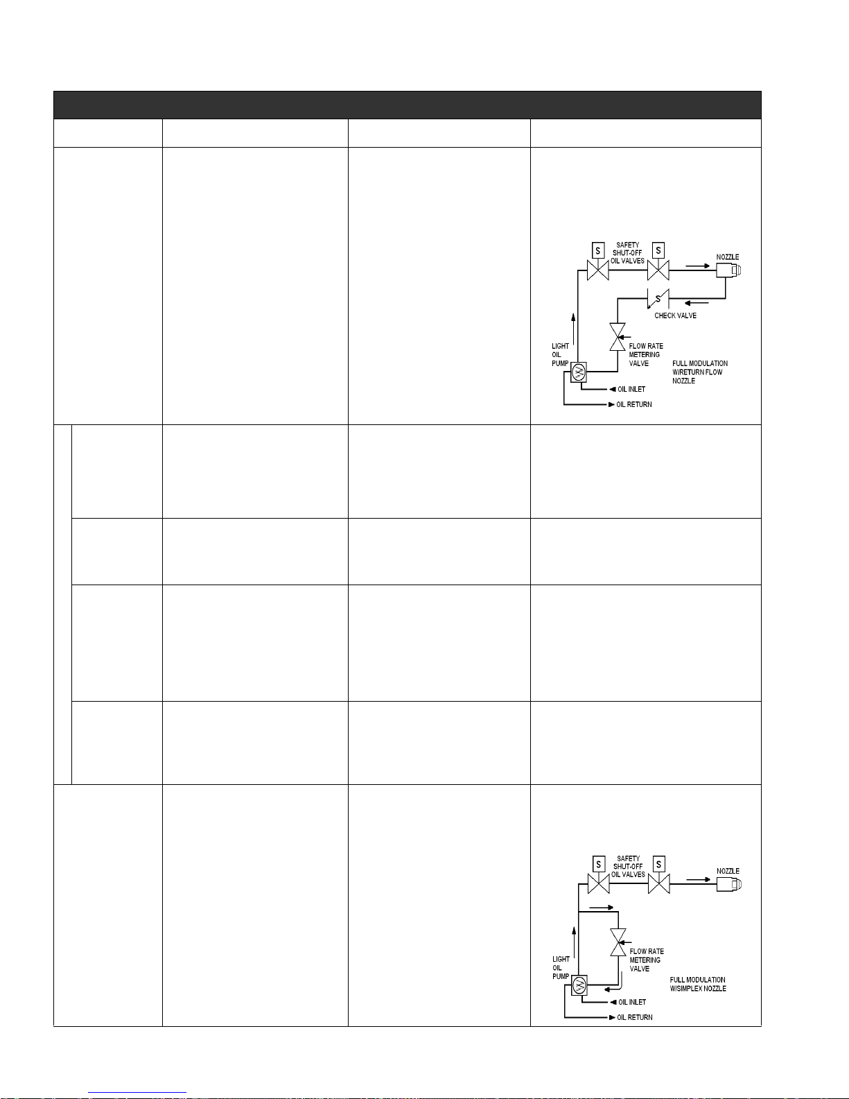
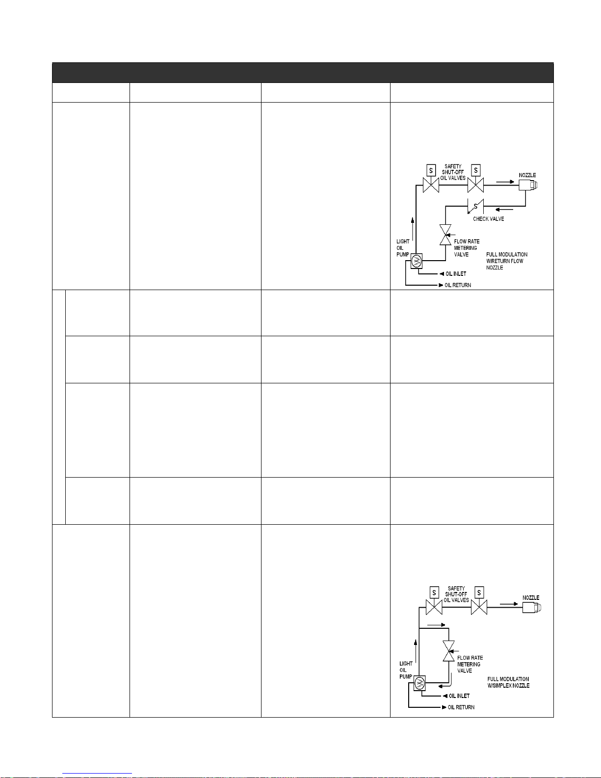
FULL MODULATION - OPEN DAMPER PURGE
Combustion Air Gas Oil
A two blade damper is controlled by a
proportional modulating actuator (or
COMPONENTS
DESCRIPTION
PRE-PURGE
STARTUP,
IGNITION
RUN,
MODULATE
Operating Sequence
SHUT DOWN,
POST-PURGE
VARIATIONS:
motor) with mechanical linkage. The
modulating actuator is capable of
stopping at any point along its 90
degree stroke based on a signal from
a remotely connected modulating
control or from a burner mounted
manual potentiometer which is
selected through an auto/manual
modulation selector switch. The
actuator also contains two internal
switches that ensure the damper
reach the high fire and low fire
positions during purge and before
ignition is initiated.
From its closed position the damper
is driven open by a signal from the
flame safeguard control where the
high fire air switch is proven. The
damper will remain open for the
duration of the pre-purge cycle.
Damper returns to the low fire position
which is proven through the internal low
fire air proving switch. The burner is now
ready for startup.
Damper is driven by the modulating
actuator to a firing rate position as
determined by the modulating control or
manual potentiometer. Actuator can
complete full travel to high fire in 30
seconds. Actuator will then continue to
adjust firing rate position based on signals
from the modulating control until demand
is satisfied.
Damper returns to its starting position
based on the 30 second closure speed of
the mechanical actuator during post purge.
Options are available for 4-20amp
modulating signal conversion or 4-20
proportional modulating actuators.
Also optional is an actuator with dual
low fire start switch positions for
improved "turn down" in dual fuel
situations.
Safety shut off valve(s) are provided
to initiate the flow of gas. The
primary is a diaphragm or motorized
type valve which have delayed
opening rates to prevent an "in rush"
of gas. A butterfly type gas metering
valve is linked directly to the damper
actuator and provides gas flow
metering relative to the actuators
position . A manually adjusted gas
regulator limits maximum firing rate.
Valves are closed.
Valves open. To prevent a surge the
primary gas valve opens at a slowed rate.
Gas flow to the manifold is metered based
on the butterfly valve low fire setting.
The gas valves remain in their open
position. As the actuator begins it's travel
to the firing rate position it is also
adjusting the butterfly gas metering valve
increasing the flow of gas to the manifold.
The burner will continue to modulate as
described under the combustion air
heading until demand is satisfied.
On shut down all gas valves close within 1
second. The butterfly valve closes in 30
seconds with the damper actuator.
None
Pressure Atomization: Two solenoid type safety shut
off oil valves initiate the flow of oil from the high
pressure pump to a return flow nozzle. In the return
line from the nozzle an adjustable oil metering valve
limits the amount of oil allowed to return to the pump.
The metering valve is connected to the damper
actuator with mechanical linkage.
The pump is operational but the valves are
closed. Oil is flowing through an internal relief
valve and returning to the supply system.
Safety shut off valves open allowing oil to flow from
pump to nozzle. Oil pressure at the nozzle is based on
the pump's pressure setting less the volume of oil
returning through the metering valve.
The safety shut-off oil valves remain open. As the
actuator begins it's travel to the firing rate position it is
also adjusting the oil metering valve decreasing the
amount of oil allowed to return to the pump. This in
turn is increasing the pressure and volume of oil at the
nozzle. The burner will continue to modulate as
described under the combustion air heading until
demand is satisfied.
All valves immediately close. The metering valve
opens to it's low fire position in 30 seconds with the
damper actuator. The oil pump is operating with postpurge, but oil is flowing through an internal relief valve
and returning to the supply system.
On models with a simplex nozzle oil is diverted
from the supply line through the meter and
back to the pump before the first safety shut-off
valve.
750-177 2-15
Page 28
Chapter 2 Profire V Burner
PARALLEL POSITIONING
Combustion Air Gas Oil
COMPONENTS
DESCRIPTION
NOTE: Parallel Positioning systems
incorporate independent actuators to
control each of the fuel and air metering
devices. Customizable "curves" can then
be created for each actuator to optimize
burner performanc e.
A two bladed damper is
controlled by an independent
parallel positioning actuator.
The remote mounted
modulating control
Safety shut off valve(s) are
provided to initiate the flow of
gas. The primary is a
diaphragm or motorized type
valve which have delayed
opening rates to prevent an "in
rush" of gas. A butterfly type
gas metering valve is directly
coupled to a parallel positioning
actuator. A manually adjusted
gas regulator limits maximum
firing rate.
Pressure Atomization: Two solenoid type safety
shut off oil valves initiate the flow of oil from the high
pressure pump to a retu rn flow nozzle. In the return
line from the nozzle is an adjustable oil metering
valve which limits the amount of oil allowed to return
to the pump. The metering valve is direct coupled to
a parallel positioning actuator.
PRE-PURGE
STARTUP,
IGNITION
RUN,
MODULATE
Operating Sequence
SHUT DOWN,
POST-PURGE
From its closed position the damper is
driven open by a signal from the parallel
positioning control. The damper will
remain open for the duration of the prepurge cycle.
Damper returns to the low fire position in
preparation for startup.
Damper is driven by its parallel
positioning actuator to a firing rate
position as determined by the parallel
positioning control. The actuator and
parallel positioning control will then
continue to adjust the damper and fuel
actuators position based on signals from
remote sensors until demand is satisfied.
Damper returns to its closed position
during or following post pu rge.
Valves are closed.
Valves open. To prevent a surge the
primary gas valve opens at a slowed
rate. Gas flow to the manifold is metered
based on the butterfly valves low fire
setting.
The gas valves remain in their open
position. The metering valve and
actuator increases the flow of gas to the
manifold in conjunction with the opening
damper however, position adjustments
are made based on the fuel "curve"
stored in the parallel positioning control's
memory. The burner will continue to
modulate as described under the
combustion air heading until demand is
satisfied.
On shut down all gas valves close within
1 second. The butterfly valve returns to
it's starting position..
The pump is operational but the valves are
closed. Oil is flowing through an internal relief
valve and returning to the supply system.
Safety shut off valves open allowing oil to flow from
pump to nozzle. Oil pressure at the nozzle is based
on the pump's pressure setting less the volume of
oil returning through the metering valve.
The safety shut-off oil valves remain open. The
metering valve and actuator decreases the flow of
oil returning to the pump in conjunction with the
opening damper however, position adjustments are
made based on the fuel "curve" stored in the parallel
positioning control's memory. This in turn is
increases the pressure and volume of oil at the
nozzle. The burner will continue to modulate as
described under the combustion air heading until
demand is satisfied.
All valves immediately close. The metering valve
opens to it's low fire position. The oil pump is
operating with post-purge, but oil is flowing through
an internal relief valve and returning to the supply
system.
On models with a simplex nozzle oil is
diverted from the supply line through the
meter and back to the pump before the
first safety shut-off
valve.
Several parallel positioning
VARIATIONS
systems available. Consult the
factory for types and options.
2-16 750-177
None
Page 29

Profire V Burner Chapter 2
C. Startup and Operation
When the installation is complete and all electrical, fuel,
water, and vent stack connections are made, make certain the
connections are tight. The operator should become familiar
with the burner, boiler controls and components. To identify
controls and components, refer to drawings and contents of
Section 1. Adjustment procedures given in Section 4 should
be reviewed prior to firing. The wiring diagram should also
be studied along with the operating sequence of the burner
programmer. Check the electrical power supply for
accordance with the nameplate specifications for all motors
and controls.
Read and understand starting instructions before attempting
to operate the burner. The following checks must be made:
BOILER
Check boiler water level. Be sure all boiler valves are
installed correctly and positioned properly. Set the high limit
control slightly above the operating control. Set operating
control at the desired temperature or pressure.
BURNER
For protection in shipment, the flame safeguard control
chassis is shipped unmounted. Check all screw connections
before attaching flame safeguard chassis to base. The screw
must be secure to assure low resistance connections. The
relay chassis is mounted on the subbase with a screw which,
when tightened, completes the connection between the
subbase and chassis contacts. Press manual reset button to be
sure safety switch contacts are closed.
Check fuses in main panel and in the burner control cabinet.
Check wiring to the burner control cabinet for compliance
with the wiring diagram and local codes. The control cabinet
components are 120 volt. If a control transformer is supplied,
ensure that the supply voltage matches its primary voltage.
Check motor rotation by momentarily closing the starter or
relay. Blower rotation is clockwise when viewed from the
drive end.
Check the pilot electrode setting. Refer to the Adjustment
section.
Check control linkage for proper movement of the air volume
damper and fuel metering components. This can be done by
loosening the linkage at the actuator lever and manipulating
by hand.
Check the air shutter and adjust low-fire setting. Refer to the
Adjustment setting.
FIRING PREPARATIONS
Check to make certain that all plugs, connections. linkages,
etc., are tight. Prior to initial firing, oil flow and pressure
should be verified.
GAS BURNERS
A representative of the gas utility should turn on the gas.
Determine by a test gauge upstream of the burner regulator
that sufficient pressure exists at the entrance to the gas train.
The gas pressure regulator must be adjusted to the pressure
required and the pressure setting recorded.
On combination fuel models, set the selector switch to gas.
On initial startup it is recommended that the main gas shutoff
cock remain closed until the programmer has cycled through
pre-purge and pilot sequences to determine that the main gas
valve opens. Turn the burner switch OFF and let the
programmer finish its cycle. Check to see that the gas valve
closes tightly.
On burners equipped with high and low gas pressure
switches, set switch pressure actuating levels and record
settings for future service reference.
See the burner specification nameplate inside the control
panel door for minimum and maximum input rate and
required manifold pressure.
When the conditions covered above and in Section 2 are
assured, the burner is ready for firing. Refer to Section E for
starting and operating information.
OIL BURNERS
Prior to initial firing, oil flow and pressure should be verified.
If the burner is a dual fuel model, make certain that the main
gas shutoff cock is closed and the fuel selector switch is set to
OIL.
OIL FLOW
If the oil supply tank is below the level of the oil fuel unit, it
is recommended that the suction line be primed with oil prior
to starting the pump to avoid the possibility of damage to the
pump through operation without lubrication.
To check for proper pump rotation, momentarily energize the
starter. With rotation verified, operate the pump to determine
that oil circulation exists. Observe the oil burner pressure
gauge. If not pressure shows after a few moments, stop the oil
pump and re-prime. If the supply tank is lower than the pump,
it is possible that the initial priming of the suction line,
followed by operation of the pump, will not establish oil flow.
This might be caused by obstruction in the suction line,
excessive lift, inadequate priming, suction line leaks, etc.
Until oil flow is established, avoid prolonged operation of the
pump. If oil flow is not established after a second priming,
investigation is required.
A vacuum (or compound pressure-vacuum) gauge should be
installed at the suction port of the pump. It is advisable that
the reading be less than 15” Hg vacuum. Vacuum in excess of
this may cause unstable firing.
750-177 2-17
Page 30
Chapter 2 Profire V Burner
OIL PRESSURE AND VACUUM
If the vacuum gauge reads higher than calculated, look for
restriction in the suction line, a closed valved, kinked copper
tubing, plugged filter, sticking check valve, frozen oil line,
undersized oil line, or excessive lift.
When there is a positive head of oil at the fuel unit, either
from a gravity or by pump circulation, the pressure must not
exceed 3 psi at the fuel unit suction inlet. Special pressure
regulating valves are available for suction pressure above 3
psi. The fuel unit discharge pressure should be set at 300 psi.
BURNER SETTINGS
To ensure reliable and safe burner performance, the location
and gap setting of the electrode for direct spark igniters, and
the relative positions of the burner nozzle, diffuser, and air
baffle components must be correctly set. The air damper
blades must be adjusted, relative to the established flow rates
to provide the correct amount of air for complete efficient
combustion.
These items are preset at the factory, but must be checked
prior to placing the burner into initial service, or after
conducting any service work that may have altered their
position.
Refer to Section 4, ADJUSTMENTS, for the instructions.
COMBUSTION SETTINGS
Fuel and air flow rates are individually adjusted at low-fire
and at high-fire to achieve rated heat input, firing rate
turndown, optimum efficiency, safe operation, and the ability
to cope with environmental changes (including air
temperature, humidity, barometric pressure), and fuel
property changes. Refer to the nameplate inside the control
panel for minimum and maximum fuel input ratings.
Refer to Section 4, ADJUSTMENTS, for the instructions.
TEST EQUIPMENT
The following test equipment should be on site:
6. Stack Thermometer and Thermocouples.
!
WARNING
DANGER
!
CAUTION
DANGER
TO PREVENT POSSIBLE SERIOUS INJURY OR
DEATH, READ THE FLAME SAFEGUARD MANUAL AND FULLY UNDERSTAND ITS CONTENT
BEFORE ATTEMPTING TO OPERATE THIS
EQUIPMENT.
!
WARNING
DANGER
!
CAUTION
DANGER
SHOULD A STARTING FAILURE OCCUR FOR
ANY REASON, COMBUSTIBLE FUMES MAY FILL
THE COMBUSTION CHAMBER. NEVER
ATTEMPT TO RE-LIGHT THE BURNER UNDER
THESE CONDITIONS WITHOUT PURGING THE
CHAMBER.
SEQUENCE OF OPERATION
The programming control sequences the operation of all
controls and components through the starting, ignition, firing,
and shutdown cycle. The burner and control system are in
starting condition when:
• The operating and high limit control (temperature or
pressure) are below their cutoff setting.
• All power supply switches are closed.
• Power is present at the control panel.
Refer to the manufacturer’s literature on programming
controls and burner wiring diagrams for detailed information.
1. Combustion analyzer with O2 indication.
2. U-Tube manometer, or pressure gauge, to measure gas
pressures (main and pilot), pressures and vacuum gauge
for the oil burners.
3. Inclined manometer to measure draft pressures.
4. Smoke spot tester for oil burners and CO analyzer for
gas fired units.
5. Voltmeter/Ammeter.
2-18 750-177
ELECTRICAL INTERFACE TEST
Prior to putting the burner into service, conduct the following
test to ascertain that ignition spark will not cause the flame
relay to pull in.
GAS FIRED
Close the pilot and main line manual gas valves. Start the
burner and at time of pilot trial with just the electrical ignition
system energized. The flame relay should not pull in (should
not be energized).
Upon completion of successful test, proceed with startup
procedures.
Page 31

Profire V Burner Chapter 2
OIL FIRED
Disconnect the electrical power to the burner. Disconnect the
electric oil safety shutoff valve. Reconnect electric power.
Close the pilot line manual gas valve, if used.
Start burner and at the time of pilot trial, with just the
electrical ignition system energized. The flame relay should
not pull in.
Upon completion of successful test, disconnect power supply.
Reconnect oil safety shutoff valve and turn on manual pilot
gas valve. Reconnect power supply and proceed with startup
procedures.
STARTUP AND OPERATING GAS BURNERS:
Performing A Gas Valve Leak Test (Bubble Test)
A gas valve leak test must also be performed on the automatic
safety shutoff valves located in the main gas train prior to any
initial commissioning or subsequent maintenance of the
burner and gas train systems, where automatic valve proving
systems interlocked with the main burner safety control are
not provided. This test should be performed periodically to
ensure no leakage of valves in their closed or de-energized
position.
Refer to the diagram below when following this procedure.
The unit should be taken out of service if the unit fails any of
the following tests. Any defective part must be replaced prior
to putting the equipment back into service.
!
WARNING
DANGER
!
CAUTION
DANGER
FAILURE TO FOLLOW THIS PROCEDURE MAY
RESULT IN EXPLOSION, FIRE, PROPERTY DAMAGE, AND PERSONAL INJURY. THIS PROCEDURE MUST BE PERFORMED ONLY BY
AUTHORIZED AND QUALIFIED PERSONNEL.
1. Close (or shut off) manual valve [7] downstream of the
automatic safety shutoff valves, trapping gas pressure
between the safety shutoff valves and manual valve and
causing a flame failure. This should close the auxiliary
safety shutoff valve [4] and main gas safety shutoff
valve [5]. If both or either valve fails to close, do not
proceed further until the problem is corrected.
2. Release gas pressure at the leak test cock [8B] between
manual valve [7] and main gas safety shutoff valve [5],
then conduct a bubble test for leak through blocking
valve [5]. If no leak, close the test cock.
3. Release gas pressure at test cock [8A] and bubble test
for leak through auxiliary safety shutoff valve [4]. If no
leak is observed, close test cock and go to next step. If
either valve leaks, correct the problem and retest 10
times before proceeding.
4. When there are no valve leaks, open manual valve [7]
and relight the burner. Then close manual valve [1]. The
safety shutoff and blocking valve should close due to
low gas pressure.
5. Relight the burners. Reduce the high gas pressure switch
[6] setpoint setting until it reaches the operating gas
pressure, which should cause the auxiliary and main gas
safety shutoff valves to close from high gas pressure.
750-177 2-19
Page 32

Chapter 2 Profire V Burner
Return the setpoint to its original position before proceeding.
6. Shut off the combustion air blower. This should cause a
failure due to low air pressure and cause the safety
valves to close.
7. Reset all manual valves to their normal setting for operation. Make sure all electric valves are operating normally. Make sure all test cocks are closed before
resuming normal operation.
8. Close the downstream main and pilot gas cocks. Make
sure the ON-OFF switch is in the OFF position. Actuate
the manual reset button of the flame safeguard control to
close the safety switch contacts.
For LOW-HIGH-OFF or LOW-HIGH-LOW and FULL
MODULATION models, set the MANUAL-AUTO
switch to the MANUAL position.
9. Set the manual potentiometer to low-fire position.
10. Open the gas pilot cock. Check pressure. Normal setting
is 4” to 6” WC when the pilot is burning.
11. Set the ON-OFF switch to ON. The burner will start and
pre-purge. After pre-purge, the ignition transformer and
the gas pilot solenoid are energized.
14. When low-fire is adjusted, shut down the burner. Restart
several times to be sure the low-fire setting is suitable.
Readjust if necessary. Never start the burner with fuel
vapor in the furnace. In case of emergency, open main
power switches and close all fuel valves. After combustion adjustments are satisfactorily set, allow the heating
vessel to slowly reach normal operating pressure or temperature.
15. After the boiler has reached operating temperature or
pressure, turn the potentiometer switch in small increments to the high-fire position. Check high-fire at this
point using combustion instruments. High-fire combustion analysis typically 3% to 4% O2. Verify maximum
input rate by measuring the gas meter.
16. Do not disturb established low-fire adjustment. Allow
the burner to return to low-fire position before adjusting
high or intermediate settings. CO levels should be less
than 400 ppm on an air-free basis at all firing rates with
<50 ppm as the target value.
When conditions covered above are assured, refer to Sections
F and G.
OIL BURNERS:
On initial startup it is recommended that the main gas
shutoff cock remain closed until the programmer has
cycled through pre-purge and pilot sequence. Then
determine that the main gas valve opens. When this is
confirmed, turn the burner switch OFF and let the programmer finish its cycle. Check to see that the gas valve
has closed tightly.
If ignition does not occur, turn the burner switch OFF
and allow the programmer to recycle for a new ignition
trial.
12. Turn the burner ON and after pilot ignition when the
flame relay pulls in, the slow opening, motorized, main
gas valve is energized. Slowly open the downstream
manual shutoff gas cock. Main flame should ignite at
this time. The gas valve and air damper continue
advancing until high-fire is reached.
13. Do not repeat unsuccessful light off attempts without
rechecking burner and pilot adjustment. Vent fuel
vapors from the combustion chamber after each unsuccessful light off attempt. Set the gas low-fire rate by
adjusting butterfly valve and air linkage. Refer to the
adjustment section of this manual. Using the combustion analysis instrument, adjust the low-fire. Typical
combustion analysis for low-fire it 5% to 6% O2 on
standard turndown systems, and between 6.5% and 9%
for higher turndown systems. Verify the minimum input
rate by measuring the gas meter.
1. The fuel selector switch should be set to OIL and the
ON-OFF switch should be in the OFF position. Actuate
the manual reset button of the flame safeguard control to
close the safety switch contacts.
2. Set the ON-OFF switch to ON. The burner will start and
pre-purge. After pre-purge, the ignition transformer will
direct spark. If the flame detector proves the presence of
a satisfactory pilot, the programmer will proceed to
main flame ignition.
3. Make initial air shutter setting for smooth ignition.
Return line oil pressure should be set according to Section 4 - ADJUSTMENTS. Do not repeat unsuccessful
light off attempts without rechecking burner and pilot
adjustment. Vent fuel vapors from the combustion
chamber after each unsuccessful light off attempt. Set
the oil low-fire rate by adjusting the oil return pressure
and air linkage. Refer to the adjustment section. Using
the combustion analysis instrument, adjust the low-fire.
Typical combustion analysis for low-fire is 5% to 6%
O2.
4. When low-fire is adjusted, shut down the burner. Restart
several times to be sure the low-fire setting is suitable.
Readjust if necessary. Never start the burner with fuel
vapor in the furnace. In case of emergency, open main
power switches and close all fuel valves. After combustion adjustments are satisfactorily set, allow the heating
vessel to slowly reach normal operating pressure or tem-
2-20 750-177
Page 33

Profire V Burner Chapter 2
perature.
5. After the boiler has reached operating temperature or
pressure, turn the potentiometer switch in small increments to the high-fire position. This will cause the
metering valve to close, resulting in an increase in the
oil pressure feeding the burner nozzle. In high-fire the
oil metering valve should be in the fully closed position
and the fuel oil pressure should be about 300 psi. Check
high-fire at this point using combustion instruments.
High-fire combustion analysis typically is 3.5% to 4%
O2. Verify maximum input rate by measuring the oil
meter if available or by weighing the oil.
6. The burner should be set up and maintained to yield
smoke spot levels less than a #1 spot (ASTM D2156
Shell-Bacharach Scale) to minimize soot buildup in the
boiler.
7. do not disturb established low-fire adjustment. Allow
the burner to return to low-fire position before adjusting
high or intermediate settings.
When conditions covered above are assured, refer to F and G
of this section.
COMBINATION GAS-OIL BURNERS
In general, the combination fueled system is to be started first
using oil, because, as a fuel, oil has a greater combustion air
requirement than natural gas.
Refer to the Gas Burner or Oil Burner adjustment procedures
and to Section 4 - ADJUSTMENTS.
Once the adjustments are set for oil, shut down the burner and
restart the adjust the natural gas fuel. DO NOT READJUST
THE AIR DAMPERS. The adjustment is made by balancing
the fuel input rate against the existing flow of combustion air.
When conditions covered above are assured, refer to F and G
of this section.
Notice: SIZE 1 & 2 COMBINATION GAS/OIL
UNITS USE A DIRECT COUPLING FROM THE
BLOWER MOTOR TO THE OIL PUMP. WHEN FIRING GAS FOR AN EXTENDED PERIOD OF TIME,
THE COUPLING SHOULD BE MANUALLLY
REMOVED AND REPLACED ONL Y WHEN FIRING
OIL. IF THE COUPLING IS LEFT CONNECTED TO
THE BLOWER MOTOR, ENSURE THA T THERE IS
PROPER OIL CIRCULA TION AT ALL TIMES TO
AVOID DAMAGE AND SEIZURE OF THE PUMP.
In automatic operation, the operating cycle always proceeds
sequentially through pre-purge, pilot ignition, main flame
ignition, run and post-purge. The length of purge and ignition
trial vary according to the type of programmer used.
During the run cycle, burner input is regulated to the load
demand by the modulating pressure or temperature control on
the boiler. The burner will continue to modulate until the
operating pressure or temperature is reached.
Programmer control operation should be tested when the
burner is initially placed into service, when a control is
replaced, and at scheduled intervals in the maintenance
program.
Refer to adjustments procedures and maintenance
instructions given in Sections 4 and 5.
SHUTDOWN
When the operating limit control setting is reached or the
burner switch is turned OFF, the following sequence occurs:
The fuel valve(s) de-energize and flame extinguishes. The
blower motor continues running during post-purge (if so
equipped with post-purge feature).
At the end of the post-purge the blower motor is de-energized.
The programmer returns to its starting position and stops.
Unit is ready to restart.
Abnormal shutdown might result from motor overload flame
outage, low water, current or fuel supply interruption,
combustion or atomizing air pressure below minimum level,
tripped circuit breakers, blown fuses, or other interlock
devices. Check for cause and correct before restarting burner.
Safety shutdown caused by ignition or flame failure will
actuate a red indicator light and energize an audible alarm (if
so equipped). If the programmer has a non-recycling
interlock circuit, any interruption in this circuit during the
pre-purge or firing cycle will cause a safety shutdown. This
type of shutdown requires manual reset of the programming
control and must be corrected before operation can be
resumed.
NORMAL OPERATION
Normal operation must be with the MANUAL-AUTO switch
selector on AUTO.
750-177 2-21
Page 34

Chapter 2 Profire V Burner
D. Adjustments
While each burner is tested at the factory for correct operation
before shipment, variable conditions such as burning
characteristics of the fuel used and operating load conditions
may require further adjustment after installation to assure
maximum operating efficiency.
Prior to placing the boiler into initial service, a complete
inspection should be made of all controls, connecting piping,
wiring, and all fastenings such as nuts, bolts, and setscrews to
be sure that no damage or misadjustments occurred during
shipment and installation.
A combustion efficiency analysis made during the initial
startup will help to determine what additional adjustments are
required in a particular installation.
COMBUSTION ADJUSTMENT ON OIL AND
GAS
Efficient combustion cannot be properly judged by flame
appearance, although it may help in making preliminary
settings.
The proper settings of air-fuel ratios must be determined by
flue gas analysis. Combustion gas analysis indicates the air to
fuel ratio and the degree of complete combustion.
Instruments are available to measure carbon dioxide (CO
oxygen (O
CO
2
air levels. Only O
), and carbon monoxide (CO). At no time should
2
measurements alone be used to indicate proper excess
measurement can definitively show
2
whether sufficient air has been provided for combustion.
STACK TEMPERATURE
Net stack temperature is obtained by subtracting the ambient
temperature from the flue gas temperature. A high net stack
temperature indicates wasted heat. Decreasing either the
temperature or the volume of the flue gas, or both can reduce
stack heat loss. Flue gas temperature is reduced by improving
heat transfer or by reducing excess combustion air. A certain
amount of excess air is necessary to complete combustion.
More efficient burners require minimum excess air.
SMOKE MEASUREMENT
Smoke measurements can be made using a variety of
different methods. The standards will vary somewhat
according to the equipment used, and instructions
accompanying the instrument should be followed.
Smoky combustion can result from:
• improper air delivery
• insufficient draft
• improper fuel viscosity
• improper fuel-air ratio
• excessive air leaks in the combustion chamber
2
• improper fuel oil temperature
TEST EQUIPMENT
The following test equipment should be used to set up and
adjust the burner correctly:
1. Combustion analyzer with O
indication.
2
2. U-Tube manometer, or pressure gauge, to measure gas
pressures (Main and Pilot), vacuum and pressure gauges
for oil.
3. Inclined manometer to measure draft pressures.
4. Smoke spot tester for oil burners and CO analyzer for
gas fired units.
5. Voltmeter/Ammeter.
6. Stack Thermometer and Thermocouples.
AIR FLOW ADJUSTMENTS
The V/Series burners have a two-blade air shutter design.
Both blades are coupled together, and attached to the
modulation motor. Changing the positions of the linkage rods
on the linkage control arms will change the way the damper
blades open and close.
),
COMBUSTION SETTINGS
Fuel and air flow rates are individually adjusted at low-fire
and at high-fire to achieve rated input, firing rate turndown,
optimum efficiency, safe operation, and the ability to cope
with environmental changes (including air temperature,
humidity, barometric pressure), and fuel property changes.
Turndown capability for oil is less than that for gas due to the
excess air requirement of oil for clean combustion. Therefore,
on combination fueled burners, gas turndown performance
may be restricted (or determined) by the excess air levels set
initially for oil combustion. For burners equipped with the
optional Siemens modulating motor, gas turndown will not be
limited to the oil setting. Each fuel will have a separate
modulation range, independent of each other.
Two key components residing in flue gas are used to optimize
combustion efficiency are excess air and unburned fuel. The
system should be adjusted to the minimum excess air quantity
that provides low levels of unburned fuel with sufficient
remaining oxygen to cope with normal atmospheric and fuel
related changes. Unburned fuel is measured as carbon
monoxide (CO) when burning natural gas, and smoke spots
when burning oil.
GAS ADJUSTMENTS
Low-fire combustion analysis typically is 6% to 9% O
less than .04% CO (400 ppm). High-fire reading typically is
3% to 5% O
and less than .04% CO. The V/Series burners
2
and
2
2-22 750-177
Page 35

Profire V Burner Chapter 2
are capable of operating at low excess air and less than 50
ppm CO levels at all firing rates.
FUEL OIL ADJUSTMENTS
Adjust for a “clean fire.” Typically for No. 2 oil, O
6% at low-fire and 3.5% to 4.5% at high-fire.
The burner should be setup and maintained to yield smoke
spot levels less than a #1 spot (ASTM D2156 ShellBacharach Scale) to minimize soot build up in the boiler.
is 5% to
2
GAS PILOT FLAME ADJUSTMENT
Burner models VG-VLG and VL-60 to 168 are equipped with
a gas pilot system. The gas pilot flame is regulated by
adjusting the pressure setting of the pilot regulator. Normal
setting is 4” to 6” W.C. when the pilot is burning. The flame
must be sufficient to be proven by the flame detector and
ignite the main flame. Although it is possible to visibly adjust
the size of the pilot flame, obtain a proper DC volt or
microamp reading of the flame signal.
The flame safeguard amplifier has a meter jack for this
purpose. At initial startup and during planned maintenance,
test the pilot flame signal, pilot turndown, and safety switch
lockout. Refer to the flame safeguard instruction manual.
1. Lockout and tag the electrical power supply to the
burner to prevent inadvertent operation during checkout
or maintenance activities.
2. Disconnect the high voltage power supply from the oilspark-ignition electrodes (if installed).
3. Disconnect the oil piping from the side of the blast tube.
4. Remove the fasteners that secure the drawer to the side
of the burner housing, and remove the complete assembly.
For burners with a gas pilot:
1. Disconnect the pilot line and loosen the locking screws
on the pilot access cover located on the side of the blast
tube.
2. Disconnect the high voltage ignition cable by pulling it
straight back, away from the pilot assembly. The pilot
assembly will slide back away from the diffuser.
3. Turn the assembly and retract it through the access hole.
4. Check the electrode position.
5. Re-assemble in reverse order.
!
WARNING
DANGER
!
CAUTION
DANGER
AN ULTRA-VIOLET FLAME SENSOR ELECRICAL
SPARK INTERFERENCE TEST MUST BE PERFORMED AFTER FINAL ADJUSTMENT. SEE SECTION 3 OF THIS MANUAL FOR ADDITIONAL
INFORMATION.
Check the pilot electrode setting. The pilot is accessible by
loosening the four screws on the side of the blast tube and
disconnecting the gas line.
DIRECT SPARK OIL PILOT ADJUSTMENT
Burner models VL13 to 55 are equipped with a direct spark
ignition. Remove the oil drawer assembly and check
electrode settings and nozzle size.
BURNER SETTINGS
To ensure reliable and safe burner performance, the location
and gap setting of the electrodes, and the relative positions of
the burner nozzle, diffuser, and air baffle components must be
set correctly. These items are preset at the factory, but must be
checked prior to placing the burner into initial service, or after
conducting any service work that may have altered their
position.
The nozzle/diffuser assembly must be removed from inside
the burner to enable measurement and readjustment:
Figure 2-17: Electrode Position
Measure the position of the tip of the nozzle to the diffuser
and compare to the following drawer assembly drawings. To
adjust:
1. Loosen the locking screws on the diffuser clamp.
2. Slide the diffuser clamp along the length of the burner
pipe until the correct dimension is achieved.
3. Tighten the diffuser clamp securely to the burner pipe.
Apply a lock-tight type compound to the screws before
tightening.
4. Carefully install the drawer assembly into the burner.
750-177 2-23
Page 36

Chapter 2 Profire V Burner
5. Re-connect the oil line and high voltage power cable to
the assembly.
Measure the position of the diffuser to the air baffle and
compare to the following drawer assembly drawings. To
adjust:
1. Measure the distance between the leading edge of the
diffuser and the front face of the inner ring on the air
baffle assembly.
2. If adjustment is required, loosen the burner pipe locking
setscrew located on the rear cap at the top of the fan
housing, and slide the burner pipe until the correct
dimension is achieved.
3. Tighten the burner pipe locking setscrew securely.
Figure 2-18: Assembly Drawing 1
Figure 2-19: Assembly Drawing 2
2-24 750-177
Page 37

Profire V Burner Chapter 2
Figure 2-20: Assembly Drawing 3
Figure 2-21: Assembly Drawing 4
Figure 2-22: Assembly Drawing 5
PILOT TURN DOWN TEST
For burners equipped with a gas pilot, conduct the following
test:
1. Turn the burner switch on. This will start the blower
motor and initiate the pre-purge sequence. Make sure a
pressure gauge 0”-10” W.C. or manometer is installed in
the pilot line to monitor the pilot gas pressure.
2. When the pilot comes on, put the programmer timer on
pilot hold by placing the Run-Test switch of the flame
safeguard to the “Test” position.
Refer to the flame safeguard control manual instructions.
3. Check the flame signal strength. Adjust the flame signal
by increasing or decreasing pilot gas pressure with the
regulator spring. Normal setting is 4” to 6” W.C.
4. Perform a pilot turndown test by reducing the pilot pressure very slowly until the scanner loses sight of the
flame and give a flame lockout, then reset to normal
level. Note the minimum pressure level.
5. After adjusting the pressure back to normal level, set the
programmer to the “Run” position. Main flame will
come on and the burner is in the low-fire position.
6. Start and stop the burner several times to ensure proper
pilot setting.
7.
750-177 2-25
Page 38

Chapter 2 Profire V Burner
ON-OFF BURNER ADJUSTMENTS
Refer to the burner data plate located inside the control panel
door. The data plate will list the burner information: burner
and control voltage, phase, cycle, motor amperage, maximum
and minimum fuel input settings, manifold pressure (at zero
furnace pressure). Add the furnace pressure to get the correct
manifold pressure at maximum firing rate.
These procedures assume that the pre-startup tasks, check
list, electrical interference test, and pilot turndown tests have
been performed in accordance with the instructions in this
manual.
Allow the boiler to fully warm up before making adjustments
for most efficient combustion. Refer to the boiler instruction
manual for the boiler controls settings.
GAS BURNERS
On-Off gas burners are typically equipped with a pressure
regulator, and a solenoid operated diaphragm gas valve to
control the on-off operation of the burner. Adjustments are
made by matching the correct fuel/air ratios.
1. Open the manual gas shutoff cocks.
2. Check the gas pressure at the inlet of the regulator and
the pressure downstream of the regulator. Make sure
they are in accordance with the regulator specifications.
The gas pressure required at the manifold is the pressure
that is required to fire the burner at its rated capacity. To
adjust the regulator, unscrew the cap located on top and
turn the adjustment screw clockwise to increase pres-
sure, or counterclockwise to decrease pressure.
Notice: MAXIMUM VALVE INLET PRESSURE
FOR THE V4944 IS 0.5 PSI. IF LINE PRESSURE IS
GREATER, AN OVER PRESSURE DEVICE IS TO
BE INSTALLED DOWNSTREAM OF MAIN GAS
REGULATOR (CSD-1-CF160).
3. Turn the burner switch to the “On” position.
4. Adjust the burner for a smooth ignition of the main
flame. The bleed valve adjustment controls the opening
of the V48 valve. When the controller is not calling for
heat, the coil is de-energized. The plunger in the 3-way
actuator is in the “Down” position so the bleed port is
closed and the supply port is open. Gas flows into the
top part of the valve. The gas pressure on top of the diaphragm, the weight, and the spring hold the valve
closed. On call for heat, the controller contacts close and
the coil is energized. This pulls the plunger to the “Up”
position, opening the bleed port and closing the supply
port. The gas in the top of the valve flows out through
the bleed port. This reduces the pressure on top of the
diaphragm, allowing the gas pressure below to lift the
diaphragm and open the valve.
5. Adjust the high-fire gas input to match maximum rating.
Adjust the gas regulator so the manifold pressure
matches the rating on the burner data plate. Verify and
record the readings and pressures. High-fire is typically
3.0% to 4.0% O
with a target value of less than 50 ppm
2
CO.
The burner should be adjusted to provide correct fuel flow at
a constant rate, as indicated on the burner data plate. This is
achieved by clocking the gas flow at the gas meter. The gas
utility or gas meter calibration data, should be consulted to
determine the correction factors to be applied to the meter.
Natural Gas Input Calculation Using a Meter
3
HHV = higher heating value of gas, Btu/ft
(if no data is
available, use 1000)
CF = cubic feet of gas clocked
t = gas meter clock time, seconds
Pm = meter upstream pressure (see Pref for units)
Pb = barometric pressure (see Pref for units)
Pref = 14.696 psi, or 29.92 “HG, or 406.77” W.C.
Tref = gas reference temperature, ºF (use 77 if data
unavailable)
Tg = gas temperature at meter, ºF
6. After completing all adjustments, replace the regulator
gaskets and slotted aluminum screw cap. Tighten all
linkages and marked settings. Complete the startup
report at the end of this section.
OIL BURNERS
On-Off burners use the Suntec B2TC-8931 oil pump model.
High-fire pressure adjustment is 200-300 PSI (solenoid
energized), and low-fire pressure adjustment is 100-200 PSI
(solenoid de-energized).
1. Briefly push in the starter contact and release to ensure
that the blower motor and oil pump are rotating in the
correct direction.
2. Turn the burner switch to the “On” position.
3. Make sure a pressure gauge, 0-600 PSI range, is
installed, downstream of the solenoid valves. Adjust the
burner for a smooth ignition of the main flame. Disconnect the wiring to the solenoid on the Suntec B2TC8931 oil pump. Loosen and remove knurled nut on the
solenoid. Adjust the screw, clockwise to increase lowfire oil pressure, and counterclockwise to decrease the
low-fire oil pressure, until a smooth ignition of the oil
2-26 750-177
Page 39

Profire V Burner Chapter 2
flame is obtained and a satisfactory low-fire oil flame is
established. Turn burner off and restart to ensure smooth
ignition is obtained at the set low-fire pressure. Replace
knurled nut and hand tighten.
4. Adjust the high-fire oil input to match the maximum rating. Turn the burner off and reconnect the wiring to the
solenoid valve. Restart the burner and allow burner to
go through ignition and low-fire. When the solenoid
energized, the oil pump discharge pressure is at high-fire
pressure. The high-fire pressure adjustment screw is
located on the oil pump body. Adjust the screw, clockwise to increase the pressure and counterclockwise to
decrease the pressure, until correct amount of oil pressure is obtained. The high-fire oil pressure should be
300 PSI. High-fire is typically 3.5% to 4.5% O
with
2
less than a No. 1 smoke. The burner should be adjusted
to provide the correct amount of fuel flow at a constant
rate at high-fire position as indicated on the burner data
plate, located inside the control panel.
COMBINATION GAS-OIL BURNERS
In general, the combination fueled system is to be started first
using oil, because as a fuel, oil has a greater combustion air
requirement than natural gas. After being completely
adjusted for oil combustion, the burner is restarted and
adjusted using natural gas as fuel. Combustion adjustment of
the combination burner for natural gas involves balancing the
input rate only against the existing flow of combustion air, as
established initially for oil.
Do not readjust the air shutters when turning the
combination burner for combustion of natural gas.
1. Turn the fuel selector switch to the “Oil” position.
2. Turn the burner switch to the “On” position.
3. Proceed with startup and adjustments using the same
procedures defined in the Oil Burners section.
4. After the system has been completely adjusted for oil
firing, place the burner switch “Off” and position the
fuel selector switch to “Gas.”
5. Proceed with startup and adjustments using the same
procedures defined in the Gas Burners section. Do not
alter the air settings set for oil.
Notice: FOR BURNERS EQUIPPED WITH A
SIEMENS MODULA TING MOTOR, FUEL/AIR
ADJUSTMENTS FOR EACH FUEL ARE INDEPENDENT OF EACH OTHER. REFER TO SIEMENS
MODULATING MOTOR PRODUCT LITERATURE
FOR PROPER ADJUSTMENT.
LOW-HIGH-OFF & LOW-HIGH-LOW
BURNER ADJUSTMENTS
Refer to the burner data plate located inside the control panel
door. The data plate will list the burner information: burner
and control voltage, phase, cycle, motor amperage, maximum
and minimum fuel input settings, manifold pressure (at zero
furnace pressure). Add the furnace pressure to get the correct
manifold pressure at maximum firing rate.
These procedures assume that the pre-startup tasks, checklist,
electrical interference test, and pilot turndown tests have been
performed in accordance with the instructions in this manual.
Allow boiler to fully warm up before making adjustments for
most efficient combustion. Refer to the boiler instruction
manual for the boiler control settings.
GAS BURNERS
The gas burner adjustments on a Low-High-Off system
consist of the gas pressure regulator, gas butterfly valve, low
and high gas pressure switches, and air damper assembly.
The auxiliary switch inside the M436 Mod motor makes or
breaks the High fire gas. The Low-High-Low boiler control
energizes the M436 motor, driving it to high-fire. When the
boiler control de-energizes the M436, a built-in return spring
drives it to the low-fire position.
All VG-13 to 55 use a butterfly gas valve to control the gas
flow to the burner. The M436 Mod motor controls the
position of the valve.
1. Open the manual gas shutoff cocks.
2. Check the gas pressure at the inlet of the regulator and
the pressure downstream of the regulator. Make sure
they are in accordance with the regulator specifications.
The gas pressure required at the manifold is the pressure
that is required to fire the burner at its rated capacity. To
adjust the regulator, unscrew the cap located on top and
turn the adjustment screw clockwise to increase pressure, or counterclockwise to decrease pressure.
3. Turn the burner switch to the “On” position.
4. The burner will start and be in the low-fire position.
5. After a few seconds, the O
accurate reading of the O
mally, O
levels are set between 4% to 6% at low-fire
2
for standard turndown systems on gas and 6% to 9% O
for high turndown systems, with the target value of less
than 50 ppm CO. To obtain the proper readings, adjust
the air shutter and low-fire regulator pressure.
6. Operate the boiler at low-fire until it is up to operating
pressure (steam) or temperature (hot water).
7. Bring the burner to the high-fire position. Adjust the
high-fire gas input to match maximum rating. At highfire, the butterfly valve should be near the full open
analyzer should have an
2
present in the flue gas. Nor-
2
2
750-177 2-27
Page 40

Chapter 2 Profire V Burner
position. Adjust the gas regulator so the manifold pressure matches the rating on the burner data plate. Verify
and record the readings and pressures. High-fire is typically 3% to 4% O
with less than 50 ppm CO.
2
8. Adjust the low and high gas pressure switches by turning the adjusting screw until indicator moves to a pressure slightly lower than normal operating pressure for
the low gas pressure switch, and slightly higher for the
high gas pressure switch (usually 20% below and 20%
higher than normal pressure).
9. Verify low-fire and high-fire rate by clocking the meter
as previously explained.
10. After completing all adjustments, replace the regulator
gaskets and slotted aluminum screw caps. Tighten all
linkages and marked settings. Complete the Startup
report at the end of this section.
The burner should be adjusted to provide correct fuel flow at
a constant rate, at the low-fire and high-fire position as
indicated on the burner data plate. This is achieved by
clocking the gas flow at the gas meter. The gas utility or gas
meter calibration data, should be consulted to determine the
correction factors to be applied to the meter.
Natural Gas Input Calculation Using a Meter
pressure regulating valve, remove lockscrew and adjust
pressure by turning the allen screw clockwise to
increase pressure, and counterclockwise to reduce pressure.
3. Operate the boiler at low-fire until it is up to operating
pressure (steam) or temperature (hot water).
4. Adjust the high-fire fuel input to match maximum oil
pressure. At high-fire, the pressure should be 300 PSI.
Verify and record the readings and pressures. High-fire
is typically 3.5% to 4.5% O
with less than No. 1 smoke.
2
The burner should be adjusted to provide correct fuel
flow at a constant rate, at the low-fire and high-fire position as indicated on the burner data plate.
5. Tighten all linkages and marked settings. Complete the
Startup report at the end of this section.
COMBINATION GAS-OIL BURNERS
In general, the combination fueled system is to be started first
using oil, because as a fuel, oil has a greater combustion air
requirement than natural gas.After being completely adjusted
for oil combustion, the burner is re-started and adjusted using
natural gas as fuel. Combustion adjustment of the
combination burner for natural gas involves balancing the
input rate only against the existing flow of combustion air, as
established initially for oil
3
HHV = higher heating value of gas, Btu/ft
(if no data is
available, use 1000)
CF = cubic feet of gas clocked
t = gas meter clock time, seconds
Pm = meter upstream pressure (see Pref for units)
Pb = barometric pressure (see Pref for units)
Pref = 14.696 psi, or 29.92 “HG, or 406.77” W.C.
Tref = gas reference temperature, ºF (use 77 if data
unavailable)
Tg = gas temperature at meter, ºF
OIL BURNERS
The Suntec B2TD-8842 oil pump is typically incorporated
and is a two-stage, two-step oil pump. The low-fire pressure
adjustment is 100-200 PSI (solenoid de-energized). High-fire
pressure adjustment is 200-300 PSI (solenoid energized).
1. Turn the burner switch to the “On” position.
2. Adjust low-fire with the oil pressure regulating valve to
have approximately 100 to 200 PSI, and adjust the air
shutter for a clean fire. Record the combustion reading
from the flue gas analyzer, normally 3.5% to 4.5% O
2
and less than No. 1 Smoke (Bacharach). To adjust the oil
Do not readjust the air shutter when tuning the
combination burner for combustion of natural gas.
1. Turn the fuel selector switch to the “Oil” position.
2. Turn the burner switch to the “On” position.
3. Proceed with startup and adjustments using the same
procedures defined in the Oil Burners section.
4. After the system has been completely adjusted for oil
firing, place the burner switch “Off” and position the
fuel selector switch to “Gas.”
5. Proceed with startup and adjustments using the same
procedures defined in the Gas Burners section. Do not
alter the air settings set for oil. Correct the O
levels by
2
adjusting the butterfly valve for Size 2 models, and the
regulators low and high pressures for Size 1 models.
FULL MODULATION BURNER
ADJUSTMENTS
Refer to the burner data plate located inside the control panel
door. The data plate will list the burner information: Burner
and control voltage, phase, cycle, motor amperage, maximum
and minimum fuel input settings, and manifold pressure (at
zero furnace pressure). Add the furnace pressure to get the
correct manifold pressure at maximum firing rate.
These procedures assume that the pre-startup tasks, checklist,
electrical interference test, and pilot turndown tests have been
performed in accordance with the instructions in this manual.
2-28 750-177
Page 41

Profire V Burner Chapter 2
Allow the boiler to fully warm up before making adjustments
for most efficient combustion. Refer to the boiler instruction
manual for the boiler controls settings.
GAS BURNERS
The gas burners adjustments on a full modulation burner
consist of the gas pressure regulator, butterfly gas valve, low
and high gas pressure switches (Model V30-168), and air
dampers.
1. Open the manual gas shutoff cocks.
2. Check the gas pressure at the inlet of the regulator and
the pressure downstream of the regulator. Make sure
they are in accordance with the regulator specifications.
The gas pressure required at the manifold is the pressure
that is required to fire the burner at its rated capacity. To
adjust the regulator, unscrew the cap located on top and
turn the adjustment screw clockwise to increase pressure, or counterclockwise to decrease pressure.
3. Set the Manual-Auto switch on the “Manual” position.
4. Position the manual flame control potentiometer in the
CLOSED (low-fire) position.
5. Turn the burner switch to the “On” position.
6. The burner will start and be in the low-fire position.
7. After a few seconds, the O
accurate reading of the O
mally, O
levels are set between 4% to 6% at low-fire
2
analyzer should have an
2
present in the flue gas. Nor-
2
for standard turndown systems on gas and 6% to 9% O
for high turndown systems, with the target value of less
than 50 ppm CO. To obtain the proper readings, adjust
the gas butterfly opening and air shutters. Take note of
the readings and pressures at the burner manifold and
gas train.
8. Operate the boiler at low-fire until it is up to operating
pressure (steam) or temperature (hot water). Then
increase the fuel input to the boiler by turning the manual flame control potentiometer towards OPEN in small
increments. This will cause the butterfly valve to open,
allowing more gas into the burner.
9. At each point, allow the burner to operate for a few minutes before recording the O
Observe that the O
and CO levels remain within an
2
, CO, and pressure readings.
2
acceptable limit. Adjust the pressure regulator as necessary, to correct this situation. Continue to do this until
the burner reaches high-fire (the potentiometer is at the
OPEN position).
10. Adjust the high-fire gas input to match maximum rating.
At high-fire, the butterfly valve should be near the full
open position. Adjust the gas regulator so the manifold
pressure matches the rating on the burner data plate.
Verify and record the readings and pressures. High-fire
is typically 3% to 4% O
with less than 50 ppm CO as a
2
target value.
11. Modulate the burner to low-fire. Verify the readings.
The burner should be adjusted to provide correct fuel flow at
a constant rate, at the low-fire and high-fire position as
indicated on the burner data plate. This is achieved by
clocking the gas flow at the gas meter. The gas utility or gas
meter calibration data, should be consulted to determine the
correction factors to be applied to the meter.
Natural Gas Input Calculation Using a Meter
HHV = higher heating value of gas, Btu/ft
3
available, use 1000)
CF = cubic feet of gas clocked
t = gas meter clock time, seconds
Pm = meter upstream pressure (see Pref for units)
Pb = barometric pressure (see Pref for units)
Pref = 14.696 psi, or 29.92 “HG, or 406.77” W.C.
Tref = gas reference temperature, ºF (use 77 if data
unavailable)
Tg = gas temperature at meter, ºF
12. Adjust the low and high gas pressure switches by turn-
2
ing the adjusting screw until indicator moves to a pressure slightly lower than normal operating pressure for
the low gas pressure switch, and slightly higher for the
high gas pressure switch (usually 50% below and 50%
higher than normal pressure, respectively).
13. Tighten all linkages and marked settings. Complete the
Startup report at the end of this section.
14. Turn the Manual-Auto switch to “Auto.” The burner
will now modulate according to the load demand to the
boiler.
BURNERS EQUIPPED WITH OPTIONAL FGR
VALVE FOR LOW NOx APPLICATIONS
LNV burners are equipped with an FGR (flue gas
recirculation) valve to lower the NOx emissions. An
adjustable cam is provided to adjust the FGR valve position
throughout the firing range on gas. Follow the steps for gas
above with the following additions:
1. Make sure the FGR valve is in the near closed position.
2. Start the burner up and hold at low-fire until the boiler is
at the proper operating pressure or temperature.
3. With an analyzer in the stack, adjust the FGR valve cam
screw to obtain sub 30 ppm NOx levels. DO NOT
ADJUST BURNER BELOW 20 PPM. UNSTABLE
(if no data is
750-177 2-29
Page 42

Chapter 2 Profire V Burner
COMBUSTION AND HIGH CO EMISSIONS WILL
RESULT. Monitor O
and CO levels during this process.
2
The introduction of FGR into the combustion chamber
will lower the flue O
levels. Too much FGR may
2
induce high levels of CO in the flue gas. It may be necessary to adjust the air damper blades to raise the O
2
to
proper low-fire values. If the proper NOx values can not
be reached by adjusting the cam screw, the FGR linkage
will have to be adjusted as well. Please see the section
on linkage adjustment for details.
4. Once the low-fire setting is complete, continue with the
instructions above, adjusting the cam at each screw, to
obtain the proper NOx values. Verify the values modulating back to low-fire, and adjust accordingly.
OIL BURNERS
The oil burner adjustments consist of the oil metering valve
and air shutters. The firing rate is regulated by a metering
valve in the nozzle return line. At low-fire, the arrow on the
valve points to approximately number 7, and at high-fire it is
in the closed position (no return flow), approximately at
number 2. The oil metering valve position will vary the oil
pressure to the nozzle. An oil pressure gauge should be
installed in the return line to monitor the oil pressure. Oil
pressure at low fire is approximately 80 to 100 PSI and 300
PSI at high-fire. Size 1 V10 to 25 uses a simplex nozzle, sizes
2 & 3 use a return flow nozzle.
1. Set the Manual-Auto switch on the “Manual” position.
2. Place the manual flame control potentiometer in the
CLOSED (low-fire) position.
3. Turn the burner switch to the “On” position.
4. The burner will start and be in the low-fire position.
5. Adjust low-fire with the metering valve position to have
approximately 80 to 90 PSI, and adjust the low-fire air
shutter for a clean fire. Record the combustion reading
from the flue gas analyzer, normally 4.5% to 6.5% O
2
and less than No. 1 Smoke (Bacharach).
6. Operate the boiler at low-fire until it is up to operating
pressure (steam) or temperature (hot water). Then
increase the fuel input to the boiler by turning the manual flame control potentiometer towards OPEN in small
increments. This will cause the metering valve to close,
resulting in an increase in the oil pressure feeding the
burner nozzle.
7. At each point, allow the burner to operate for a few minutes before recording the O
readings. Observe that the O
, CO, Smoke, and pressure
2
and CO levels remain
2
within an acceptable limit. Adjust the oil pressure as
necessary, to correct this situation. For burners with the
cam trim option, adjust the cam screws throughout the
range to obtain correct O
and CO levels. Continue to do
2
this until the burner reaches high-fire (the potentiometer
is at the OPEN position).
8. Adjust the high-fire fuel input to match maximum oil
pressure. At high-fire, the metering valve should be in
the fully closed position and the pressure should be 300
PSI. Verify and record the readings and pressures. Highfire is typically 3.5% to 4.5% O
with less than No. 1
2
Smoke. Adjust the high-fire excess air rate using the
high-fire shutter adjustment.
9. Modulate the burner to low-fire. Verify the readings
once again. The burner should be adjusted to provide
correct fuel flow at a constant rate, at the low-fire and
high-fire positions as indicated on the burner data plate.
10. Tighten all linkages and marked settings. Complete the
Startup report at the end of this section.
11. Turn the Manual-Auto switch to “Auto.” The burner
will now modulate according to the load demand to the
boiler.
COMBINATION GAS-OIL BURNERS
In general, the combination fueled system is to be started first
using oil, because as a fuel, oil has a greater combustion air
requirement than natural gas.After being completely adjusted
for oil combustion, the burner is re-started and adjusted using
natural gas as fuel. Combustion adjustment of the
combination burner for natural gas involves balancing the
input rate only against the existing flow of combustion air, as
established initially for oil
Do not readjust the air shutter when tuning the
combination burner for combustion of natural gas.
1. Set the Manual-Auto switch to the “Manual” position.
2. Position the manual flame control potentiometer in the
CLOSED (low-fire) position.
3. Turn the fuel selector switch to the “Oil” position.
4. Turn the burner switch to the “On” position.
5. Proceed with startup and adjustments using the same
procedures defined in the Oil Burners section.
6. After the system has been completely adjusted for oil
firing, place the burner switch OFF, and position the fuel
selector switch to “Gas.”
7. Proceed with startup and adjustments using the same
procedures defined in the Gas Burners section. Do not
alter the air setting set for oil. Correct the O
levels by
2
adjusting the butterfly valve.
2-30 750-177
Page 43

Profire V Burner Chapter 2
!
CAUTION
DANGER
ANY COVER PLATES, ENCLOS URES, OR
GUARDS ANCHORED TO THE BURNER, OR ANY
BURNER RELATED EQUIPMENT, MUST REMAIN
IN POSITION AT ALL TIMES. ONLY DURING
MAINTENANCE AND SERVICE SHUTDOWN CAN
THESE COVER PLATES, ENCLOSURES, OR
GUARDS BE ALLOWED TO BE REMOVED. THEY
MUST BE REPLACED, AND SECURELY
ANCHORED BEFORE TESTING, ADJUSTING, OR
RUNNING THE BURNER OR BURNER RELATED
EQUIPMENT.
CONTROL SYSTEM
Figure 2-23: FGR Control Valve
E. Maintenance
A maintenance program avoids unnecessary downtime,
costly repairs, and promotes safety. It is recommended that a
record be maintained of daily, weekly, monthly, and yearly
maintenance activities.
Most operating controls require very little maintenance
beyond regular inspection. Examine electrical connections.
Keep the controls clean. Remove any dust from the interior of
the control. Covers should be left on controls at all times.
Keep the control cabinet doors closed. Dust and dirt can
damage motor starters and relay contacts. Starter contacts are
plated with silver and are not harmed by discoloration. Never
use files or abrasive materials such as sandpaper on contact
points.
Electrical and mechanical devices require systematic and
periodic inspection and maintenance. Any “automatic”
features do not relieve the operator from responsibility, but
rather frees him from certain repetitive chores, providing time
for upkeep and maintenance.
Unusual noise, improper gauge reading, leak, sign of
overheating, etc. can indicate a developing malfunction
requiring corrective action.
!
WARNING
DANGER
!
CAUTION
DANGER
ONLY FACTORY AUTHORIZED BURNER SERVICE PERSONNEL SHOULD START UP, ADJUST,
OR SERVICE THE EQUIPMENT.
!
WARNING
DANGER
!
CAUTION
DANGER
ONLY FACTORY AUTHORIZED BURNER SERVICE PERSONNEL SHOULD ST AR T UP, ADJUST,
OR SERVICE THE EQUIPMENT.
PROGRAMMING CONTROL
This control requires no adjustment, nor should any attempt
be made to alter contact settings or timing logic. Those
programmers with contacts may require occasional cleaning.
If so, follow instructions given in the manufacturer’s bulletin.
Never use abrasive materials. The manufacturer’s bulletin
also contains troubleshooting information. The flame
detector lens should be cleaned as often as conditions
demand.
A periodic safety check procedure should be established to
test the complete safeguard system. Tests should verify safety
shutdown with a safety lockout upon failure to ignite the pilot
or the main flame, and upon loss of flame. Each of these
conditions should be checked on a scheduled basis. The
safety check procedures are contained in the manufacturer’s
bulletin.
750-177 2-31
Page 44

Chapter 2 Profire V Burner
MOTORS
Supply voltage to the motor must not vary more than 10%
from data plate ratings. At initial startup and regularly
thereafter, check the motor current with an ammeter while the
burner is in high-fire position. If the reading exceeds the data
plate rating plus service factor, determine the cause and
correct it. In dusty locations, clean the motor regularly to
assure adequate cooling. Lubricate in accordance with the
manufacturer’s instructions.
GAS SYSTEM
Check the gas train for leaks. Check the gas valves and verify
the ow and high gas pressure settings.
SOLENOID VALVES
A faint hum from the solenoid is normal when the coil is
energized. Should the valve fail to operate, check that there is
voltage at the valve coil. If there is no voltage at the coil,
check for loose wiring connections. If there is proper voltage
at the valve coil and the valve still fails to open, replace the
coil. Refer to manufacturer’s bulletin for correct procedure in
coil replacement.
Should it become necessary to replace the complete valve, be
sure that the flow is in the direction of the arrow on the valve
body.
Test for gas leaks and check valve action several times to
ensure proper operation before attempting to relight burner.
!
CAUTION
DANGER
ALL POWER MUST BE DISCONNECTED
BEFORE SERVICING VALVES.
MOTORIZED MAIN GAS VALVES
Should the valve fail to operate, check for voltage at the
valve. Make certain that the main shutoff cock is closed prior
to testing. The actuator is not field repairable nor should it be
disassembled. Replace the actuator if valve fails to operate.
After replacement, cycle the valve with the fuel shut off to
determine that it opens and closes. If the valve has a visual
indicator, observe its position for correct operation.
OIL SYSTEM
Little maintenance is required on the oil systems other than
cleaning the oil filter. This procedure should be done at
regular intervals. Increased inlet vacuum reading may
indicate a clogged filter. Follow the strainer manufacturer’s
maintenance schedule.
Maintenance checks on the flexible coupling between the fuel
unit and motor for alignment, tightness and wear and oil
piping connection tightness should also be made at regular
intervals. Access the coupling by removing the airbox cover
and loosening the two setscrews on the flex coupling.
The oil nozzle should be checked. Inside the nozzle lies a
small screen that keeps out any particle not caught by the
strainer. These particles will interfere with the normal oil
flow pattern exiting the nozzle. A distorted flame can indicate
a clogged nozzle. Inspect and clean the nozzle and screen. to
clean the scree, swirler, and tip, unscrew the tip from the
nozzle body. Clean nozzle parts in solvent. Never use wire or
sharp metal tools to clean the nozzle orifice. A metal tool will
distort the orifice and ruin the nozzle. Reassemble the nozzle.
The tailpiece must be screwed in with the swirler seating tight
against the tip to ensure proper atomization. Reassemble the
nozzle into the nozzle body. If a nozzle is replaced, it must be
an identical nozzle (make, size, and spray angle).
DRAWER ASSEMBLY
The drawer assembly may be removed for inspection and
service.
1. Shut off burner, place switch in “Off” position.
2. Shut off all electric power to the burner.
3. Disconnect the fuel lines from the drawer assembly
access cover.
4. After making note of where the bolts are located in relationship to the access cover slots, remove the drawer
assembly access cover bolts. Pull the drawer partially
out of the housing. Reach inside to disconnect the ignition cables from the electrodes for direct spark applications. Pull the drawer assembly completely out of the
housing.
5. To reinstall the drawer assembly, insert it part way into
the housing, connect the ignition cables, if applicable,
and seat the assembly fully. Install the access cover bolts
loosely. Slide the cover to the original location, and
tighten the bolts. Reconnect the fuel lines.
IGNITION ELECTRODE, CABLE AND
PILOT
Failure to keep electrodes clean and set in the proper position
accounts for much faulty burner operation. Not only must the
gap be correct, but the electrode points must be carefully
located with respect to the nozzle. Sometimes difficulty in
securing the electrodes in their clamps can be corrected by
using light metal shims around the porcelain. Defective or
cracked porcelains require replacement to prevent short
circuiting of the spark. A gradual wearing away of the
electrode tips may require re-spacing of the points or
replacement of the electrode.
2-32 750-177
Page 45

Profire V Burner Chapter 2
The pilot should be checked monthly for loosening of
components and carbon buildup. Before removing the pilot,
ensure that the fuel supply is shut off.
On direct spark oil units, once you have removed the drawer
assembly, check the electrode to nozzle gap and adjust if
necessary. Refer to the drawer assembly drawings in the
ADJUSTMENT section.
For burners equipped with a gas pilot, the pilot is located on
the side opposite to the main gas entrance. Close the gas pilot
cock. Disconnect the pilot gas supply line. Remove the
screws on the pilot access plate. Disconnect the high voltage
ignition cable by pulling it straight back, away from the pilot
assembly. The pilot gun assembly will slide back away from
the flame side of the burner. Once the pilot assembly is clear
of the burner head bracket, turn the pilot assembly and retract
it through the access hole. Inspect the electrode and adjust the
gap if necessary. Thoroughly clean and adjust the porcelain
insulated electrodes. Correct all variations from the clearance
dimensions. If the insulation on the high voltage cables
becomes cracked or charred, install new cables. Ignition
cable should not be exposed to moisture, abrasion, or rough
handling. See that the connectors are in perfect contact with
the cable ends. Unscrewing the snap portion of the connector
will show whether this is true.
FLAME SCANNER
The scanner must be clean. Even a small amount of
contamination will reduce the flame signal. Wipe the scanner
lens with a clean soft cloth. Check pilot and flame signal
strength.
BURNER MOUNTING INSPECTION
The seal between the burner flange and furnace front plate
must not permit combustion gasses to escape. Periodic
inspection is important. If leaking occurs, refer to the
INSTALLATION section for proper sealing procedure.
EXTENDED SHUTDOWN
When shutting down the burner for an extended period of
time, the operator should use the following general guidelines
to protect the burner from its surrounding elements.
This will add to the operating life of the burner:
1. Turn the main electrical disconnect switch to the burner
to “Off.”
2. Close all main fuel valves.
3. If the burner operates in a damp environment, cover it
with plastic to protect all electrical components from
moisture. Remove burner control and store in a dry area.
750-177 2-33
Page 46

Chapter 2 Profire V Burner
RECOMMENDED MAINTENANCE SCHEDULE
ITEM SERVICE BY REMARKS
DAILY
Gauges, Monitors, and Indicators Operator Make visual inspection and record readings in log.
Instrument and Equipment Settings Operator Make visual check against recommended specifications.
Low Water, Fuel Cutoff, and Alarms Operator Refer to instructions.
WEEKLY
Firing Rate Control Operator Verify factory settings.
Igniter Operator Make visual inspection. Check flame signal strength.
Pilot and Main Fuel Valves Operator Open limit switch. Make audible and visual check. Check valve
position indicators, and check fuel meters.
Flame Failure Controls Operator Close manual fuel supply for (1) pilot and (2) main fuel cock
and/or valve(s). Check safety shutdown timing. Record in log.
Flame Signal Strength Controls Operator Read and log the flame signal for both pilot and main flame.
Notify service if readings are very high, very low, or fluctuating.
Linkages Operator Check all burner linkages for tightness. Tighten if required.
MONTHLY
Low Fan Pressure Interlock Operator Manually adjust until switch opens.
High and Low Gas Pressure Interlocks Operator Refer to instructions. Manually adjust until switch opens.
Scanner and Diffuser Operator Check, inspect, and clean for soot buildup.
Pilot Assembly Operator Check for loosening of components, erosion, or carbon buildup.
QUARTERLY
Burner Mounting Flange Operator Check tightness of burner mounting flange and burner drawer.
Handhole Covers Operator Check tightness of handhole plates on upper and lower drum.
Sight Glass (steam only) Operator Check for leaks around sight glass packing nuts.
ANNUALLY
Strainer (Oil Units) Operator Replace or clean the oil strainer element.
Impeller Operator Inspect and clean the combustion impeller.
Combustion Test Service Techni-
cian
Pilot Turndown Test Service Techni-
cian
Operating Controls Service Techni-
cian
Perform complete combustion test. Adjust burner if necessary.
Read and log data.
Required after any adjustment to flame, scanner, or pilot adjustment.
Refer to instructions.
2-34 750-177
Page 47

Profire V Burner Chapter 2
F. Troubleshooting
PROBLEM SOLUTION
Burner Does Not Start 1. No voltage at program relay pwoer input terminals.
a. Main disconnect switch open.
b. Blown control circuit fuse.
c. Loose or broken electrical connection.
2. Program relay safety switch requires resetting.
3. Limit circuit not completed - no voltage at end of limit circuit program relay terminal.
a. Pressure or temperature is above setting of operation control.
b. Water below required level.
•Low-water light (and alarm horn) should indicate this condition.
•Check manual reset button, if provided, on low-water control.
c. Fuel pressure must be within settings of low pressure and high pressure
switches.
d. Check burner air proving switch and high-fire limit switch.
4. High or low gas pressure - investigate and repair.
750-177 2-35
Page 48

Chapter 2 Profire V Burner
PROBLEM SOLUTION
No Ignition 1. Lack of spark.
a. Electrode grounded or porcelain cracked.
b. Improper electrode setting.
c. Loose terminal on ignition cable, cable shorted.
d. Inoperative ignition transformer.
e. Insufficient or no voltage at pilot ignition circuit terminal.
2. Spark but no flame.
a. Lack of fuel - no gas pressure, closed fuel valve, empty tank, broken line.
b. Too much air flow.
c. No voltage to pilot solenoid.
d. Defective pilot solenoid.
e. Improperly positioned electrode (direct spark models).
3. Low -fire switch open in low-fire proving circuit.
a. Damper motor not closed, slipped cam, defective switch.
b. Damper jammed or linkage binding.
4. Running interlock circuit not completed.
a. Combustion proving switches defective or not properly set.
b. Motor starter interlock contact not closed.
5. Flame detector defective, sight tube obstructed, or lens dirty.
PROBLEM SOLUTION
Pilot Flame, But No Main Flame 1. Insufficient pilot flame.
2. Gas fired unit.
a. Manual gas cock closed.
b. Main gas valve inoperative.
c. Gas pressure regulator inoperative.
3. Oil fired unit.
a. Oil supply cut off by obstruction, closed valve, or loss of suction.
b. Supply pump inoperative
c. No fuel. Broken, loose or missing oil pump coupling.
d. Main oil valve inoperative.
e. Check oil nozzle, gun and lines.
2-36 750-177
4. flame detector defective, sight tube obstructed or lens dirty.
5. Insufficient or no voltage at main fuel valve circuit terminal.
Page 49

Profire V Burner Chapter 2
PROBLEM SOLUTION
Burner Stays in Low-Fire 1. Pressure or temperature above modulating control setting.
2. Manual-automatic switch in wrong position.
3. Inoperative modulating motor.
4. Defective modulating control.
5. Binding or loose linkages, cams, setscrews, etc.
PROBLEM SOLUTION
Shutdown Occurs During Firing 1. Loss or stoppage of fuel supply.
2. Defective fuel valve, loose electrical connection.
3. Flame detector weak or defective.
4. Scanner lens dirty or sight tube obstructed.
5. If the programmer lockout switch has not tripped, check the limit circuit for an
opened safety control.
6. If the programmer lockout switch has tripped:
a. Check fuel lines and valves.
b. Check flame detector.
c. Check for open circuit in running interlock circuit.
d. The flame failure light is energized by ignition failure, main flame failu re, inad-
equate flame signal, or open control in the running interlock circuit.
7. Improper air/fuel ratio.
a. Slipping linkage.
b. Damper stuck open.
c. Fluctuating fuel supply.
•Temporary obstruction in the fuel line.
•Temporary drop in gas pressure.
8. Interlock device inoperative or defective.
9. air in the oil lines. Bleed lines.
750-177 2-37
Page 50

Chapter 2 Profire V Burner
PROBLEM SOLUTION
Modulating Motor Does Not
Operate
1. Manual-automatic switch in wrong position.
2. Linkage loose or jammed.
3. Motor does not drive to open or close during pre-purge or close on burner shut-
down.
a. Motor defective.
b. Loose electrical connection.
c. Damper motor transformer defective.
4. Motor does not operate on demand.
a. Manual-automatic switch in wrong position.
b. Modulating control improperly set or inoperative.
c. Motor defective.
d. Loose electrical connection.
e. Damper motor transformer defective.
2-38 750-177
Page 51

Profire V Burner Chapter 2
G. B u r ne r S p ec s
Model FLX Burner Characteristics
Model No.
FLX-150 1500 PFVLG-15 1 15/230/1/60
FLX-200 2000 PFVLG-20 1 15/230/1/60
FLX-250 2500 PFVLG-25 1 15/230/1/60
FLX-300 3000 PFVLG-30 1 15/230/1/60
FLX-350 3500 PFVLG-35 208/230/1/60
FLX-400 4000 PFVLG-40 208/230/1/60
FLX-450 4500 PFVLG-45 208-230/460/3/60
FLX-500 5000 PFVLG-50 230/460/3/60
FLX-550 5500 PFVLG-55 230/460/3/60
FLX-600 6000 PFVLG-60 460/3/60
FLX-700 7000 PFVLG-70 460/3/60
FLX-800 8000 PFVLG-80 460/3/60
FLX-900 9000 PFVLG-90 460/3/60
FLX-1000 10000 PFVLG-100 460/3/60
FLX-1100 11000 PFVLG-110 460/3/60
FLX-1200 12000 PFVLG-120 460/3/60
Burner Maximum
Input MBH
Burner Model
Fan Motor (3450 RPM)
Volta g e
Notes:
1. Burner model selection shown is subject to changed and is based on actual application (altitude, gas pressure, reduced
NOx, etc.)
2. Standard voltage for Canadian application is 575/3/60.
3. Burner operation is Full Modulation on Elite Series and for the Econo series Low-High-Low for units 150 - 600 and modulated firing on 700 and greater.
4. Burner models shown are for combination gas/oil firing. For straight gas, delete the letter L, and for straight oil, delete the
letter G.
750-177 2-39
Page 52

Chapter 2 Profire V Burner
Model FLX Minimum Required Gas Pressure
Model No.
Std. Gas Train Size
(In.) Note 3
Min. Gas Pressure
(in WC) Note 4
Min. Gas Pressure
(in WC) Note 5
Burner Model
FLX-150 1 11.2 12.5 PFVG-15
FLX-200 1 19.4 21.7 PFVG-20
FLX-250 1.5 12.4 15.7 PFVG-25
FLX-300 1.5 15.9 20.7 PFVG-30
FLX-350 1.5 15.5 22.0 PFVG-35
FLX-400 1.5 18.7 27.2 PFVG-40
FLX-450 2 16.0 26.7 PFVG-45
FLX-500 2 17.6 21.0 PFVG-50
FLX-550 2 22.9 27.1 PFVG-55
FLX-600 2 20.0 24.9 PFVG-60
FLX-700 2 25.2 31.9 PFVG-70
FLX-800 2.5 19.9 22.2 PFVG-80
FLX-900 2.5 24.7 27.7 PFVG-90
FLX-1000 2.5 31.6 31.6 PFVG-100
FLX-1100 2.5 37.3 37.3 PFVG-110
FLX-1200 2.5 38.2 38.2 PFVG-120
Notes:
1. Table is based on 1,000 Btu/cu. ft. natural gas and elevation of 1,000 feet.
2. Minimum gas pressure also applies to 200 fuel series.
3. As an option, the standard gas train can be replaced with an oversized design to reduce inlet gas pressure requirements.
4. Use this column for all U.S. installations.
5. Use this column for all Canadian installations.
2-40 750-177
Page 53

Profire V Burner Chapter 2
START-UP / SERVICE REPORT
The following information should be filled in by the service technician at start-up or after any adjustment to the burner.
A copy of the start-up report MUST be returned to CB in order to validate the warranty of the burner.
Burner Model Serial Number Start-up Date
GAS OIL
Test Conducted
Firing Rate MMBtu / gph
Stack Temp (Gross) oF
Room Temp oF
O2%
CO2%
CO (PPM)
NOx (PPM)
Smoke (Bacharach)
Combustion Eff.%
Stack Draft "W.C.
Furnace Pressure "W.C.
Blast tube Pressure "W.C.
Steam Pressure PSIG
Water Temperature oF
Supply oil pressure PSIG
Return oil pressure PSIG
Vacuum oil pump "HG
Oil Temperature
Atom. air pressure
Gas Pressure @ Burner Inner Manifold
Manifold "W.C. Outer Manifold
Center Gas pressure "W.C.
Gas Pressure @ Regulator Inlet PSIG
Gas Pressure @ Regulator Outlet PSIG
Pilot Gas Pressure @ Regulator Outlet "W.C.
Flame Signal Main Low 50% High
Electric Motors L1 L2 L3 L1 L2 L3
Control Voltage
Blower Motor
Air Compressor
Air-Oil or Metering
Low 50% High Low 50% High
Voltage Amperage
Control Checks Test Set Point
Low Water Cut Off
Aux. LWCO
High Water Cut Off
Operating Limit
High Limit
Operating Control
Stack Temp Interlock
Flame Failure
Combustion Air Switch
High Purge Switch
Low Fire Interlock
Oil Pressure Switch
Oil Valve with P.O.C.
Interlock
High Gas Pressure
Switch
Low Gas Pressure
Switch
Gas Valve P.O.C.
Interlock
Pilot Turndown Test
Flame Signal Pilot
(For Low NOx Burners)
Blast Tube Temp.
Interlock
FGR Line Purge Switch
FGR Valve P.O.C.
Switch
Adjusted by:
Date:
Accepted by:
(Signature Required)
750-177 2-41
9028-BC
Page 54

Chapter 2 Profire V Burner
2-42 750-177
Page 55

CHAPTER 3
Pressure Vessel Care
A. General. . . . . . . . . . . . . . . . . . . . . . . . . . . . . . . . . . .3-1
B. Water Requirements (Hot Water Boilers) . . . . . . . .3-1
C. Water Requirements (Steam Boilers . . . . . . . . . . . .3-3
D. Water Treatment . . . . . . . . . . . . . . . . . . . . . . . . . . .3-4
E. Blowdown . . . . . . . . . . . . . . . . . . . . . . . . . . . . . . . .3-4
F. Cleaning . . . . . . . . . . . . . . . . . . . . . . . . . . . . . . . . . .3-6
G. Boilout . . . . . . . . . . . . . . . . . . . . . . . . . . . . . . . . . . .3-6
H. Washing Out . . . . . . . . . . . . . . . . . . . . . . . . . . . . . .3-8
I. Periodic Inspections . . . . . . . . . . . . . . . . . . . . . . . . .3-8
J. Preparation for Extended Layup . . . . . . . . . . . . . . . .3-9
A. GENERAL
This chapter is devoted primarily to the waterside care of the
pressure vessel.
B
A
C
Proper water supply and treatment are essential to boiler life
and length of service. Proper water treatment will pay
dividends in the form of longer life, less downtime, and
prevention of costly repairs.
Hot water boilers require proper circulation. The system must
be operated as intended by its designer in order to avoid the
possibility of thermal shock with severe stress to the pressure
vessel.
Although it is of prime importance, the subject of water
supply and treatment cannot adequately be covered in this
manual. For specific information or assistance with your
water treatment requirements, contact your local CleaverBrooks authorized representative.
B. WATER REQUIREMENTS
(HOT WATER BOILERS)
Air Removal
The hot water outlet (Figure 3-1) is located in the top drum of
the boiler. This location reduces the possibility of released air
(which is trapped at the top of the drum) from entering the
system. Any air (or oxygen) that may be released in the boiler
will collect at the top of the upper drum, where it will escape
C
A. HOT WATER OUTLET
B. AIR BLEED TAPPING
C. PRESSURE/TEMPERATURE GAUGES
Figure 3-1: Upper Drum (Hot Water)
through the air vent tapping (Figure 3-1). The tapping must be
properly piped to the expansion tank or a stand pipe and air
bleeder to remove gases that collect at the top of the drum.
Continuous Flow
The system must be piped and the controls arranged so that
there will be water circulation through the boiler under all
operating conditions. Constant circulation through the boiler
eliminates the possibility of stratification within the unit.
Refer to Fig. 3-1 to determine the minimum continuous flow
rate through the boiler under all operating conditions.
750-177 3-1
Page 56

Chapter 3 Pressure Vessel Care
DT = 20°FDT = 40°FDT = 60°FDT = 80°F DT = 100°F
MODEL
NO.
FLX-150 1.14 122.0 0.30 61.1 0.13 41.1 0.08 30.8 0.05 24.4
FLX-200 1.14 162.3 0.30 81.1 0.13 54.1 0.08 40.6 0.05 32.5
FLX-250 1.77 202.8 0.46 101.4 0.21 67.6 0.12 50.7 0.08 40.6
FLX-300 1.85 243.4 0.48 121.7 0.22 81.1 0.12 60.9 0.08 48.7
FLX-350 2.49 284.0 0.65 142.0 0.29 94.7 0.17 71.0 0.11 56.8
FLX-400 1.35 324.5 0.35 162.3 0.16 108.2 0.09 81.1 0.06 64.9
FLX-450 1.71 365.1 0.44 182.6 0.20 121.7 0.11 91.2 0.08 73.0
FLX-500 2.03 405.7 0.54 202.8 0.25 135.2 0.14 101.4 0.09 81.1
FLX-550 2.50 446.3 0.67 223.1 0.31 148.7 0.17 111.5 0.11 89.2
FLX-600 2.99 486.8 0.77 243.4 0.35 162.3 0.20 121.7 0.13 97.4
FLX-700 1.75 567.9 0.45 284.0 0.21 189.3 0.12 142.0 0.08 113.6
FLX-800 2.27 649.1 0.59 324.5 0.27 216.4 0.15 162.3 0.10 129.8
FLX-900 2.85 730.2 0.74 365.1 0.33 243.4 0.19 182.6 0.12 146.0
DP
(PSIG)
GPM DP (PSIG) GPM DP (PSIG) GPM DP (PSIG) GPM DP (PSIG) GPM
FLX-1000 4.08 811.4 1.02 405.6 0.42 270.4 0.25 202.8 0.15 163.6
FLX-1100 4.42 892.6 1.15 446.2 0.48 297.4 0.28 223.0 0.18 178.4
FLX-1200 6.20 973.6 1.60 486.8 0.59 324.6 0.31 243.4 0.22 194.8
Table 3-1:Minimum Flow Rates for Hot Water Boilers
System Pressure
!
CAUTION
DANGER
In order to avoid damage to the equipment,
a circulating pump should be interlocked
with the burner so that the burner cannot
operate unless the circulatin g pump is running.
It is recommended that the system circulating pumps be kept
running, even though the heat users do not require hot water.
The relief device or bypass valve will allow continuous
circulation through the boiler and will help prevent rapid
replacement of boiler water with “cold” zone water.
!
CAUTION
DANGER
The operator should determine that a circulation of water exists through the boiler before initial firing or when fi rin g af te r t he uni t
has been drained and refilled. A reduced c irculation of water or no water circulation
through the boiler when the burner is operating may result in damage to the equipment.
The design of the system and the usage requirements often
will dictate the pressure exerted upon the boiler. Some
systems are pressurized with nitrogen. Caution must be
240
F
230
°
220
210
200
190
180
170
SUPPLY WATER TEMPERA T URE -
160
150
10 12 14
16 18 20 22 24
SYSTEM PRESSURE - PSI
26
28
30
Figure 3-2: Minimum System Operating Pressure
3-2 750-177
Page 57

Pressure Vessel Care Chapter 3
exercised to make sure that the proper relationship of pressure
to temperature exists within the boiler so that all of its internal
surfaces are fully wetted at all times. It is for this reason that
the internal boiler pressure, as indicated on the water pressure
gauge, must be held to the level shown in Figure 3-3.
It is advisable to install a thermometer in the return line to
indicate return water temperature. With the return water
temperature and the supply water temperature to the system
known, the temperature differential will be established.
Knowing the flow rate, the operator easily can detect any
excessive load condition and take appropriate corrective
action.
Pressure Drop
There will be a pressure drop of less than 4 psi through all
standardly equipped Cleaver-Brooks boilers operating in any
system that has more than the 20°F temperature drop. This
drop will vary with boiler size and circulation rate. For
specific information, refer to table 3-1, Minimum Flow Rates
for Hot Water Boilers.
Minimum Boiler Outlet Water Temperature
The minimum recommended operating boiler outlet water
temperature is 150°F. When water temperatures lower than
150°F are used, the combustion gases are reduced in
temperature to a point where the water vapor in the gases
condenses. A result of condensation is that fireside corrosion
occurs in the boiler and breeching. The condensation problem
is more severe on a unit that operates intermittently or is
oversized for the actual load. This is not a matter that can be
controlled by boiler design, since an efficient boiler extracts
all the possible heat from the combustion gases.
Note: In order to maintain a minimum outlet
water temperature of 150°F the low limit of
the Operating Temperature Control should
be set at least 10° higher.
If the operating water temperature going to the system must
be lower than 150°F, the operating boiler outlet water
temperature should still be held to a minimum of 150°F.
Mixing valves are used to reduce the supply temperature
going to the system.
Multiple Boiler Installations
When multiple boilers of equal or unequal size are installed,
care must be taken to ensure proportional flow through the
boilers. Proportional flow can best be accomplished by use of
balancing cocks and gauges in the supply line from each
boiler. If balancing cocks or orifice plates are used, a
significant pressure drop (for example, 3-5 psi) must be taken
across the balancing device to accomplish proportional flow.
Variations in water temperature and firing rates will result if
care is not taken to ensure proportional flow through the
boilers. In extreme cases, differences in firing rates could
result in a net header water temperature below the desired
temperature.
C. WATER REQUIREMENTS
(STEAM BOILERS)
Deaeration
The most important factor in the life of a steam pressure
vessel is the proper conditioning of the boiler feed water.
Corrosive gasses, such as oxygen and carbon dioxide, must
be removed from the feed water in order to prevent
degradation of the pressure vessel. For this reason CleaverBrooks recommends the use of a deaeration system as an
integral part of a complete boiler installation. If
circumstances do not allow the implementation of a
deaeration system, then serious consideration should be given
to effective alternatives such as a feed water preheater
combined with a chemical oxygen scavenger. Complete
boiler water chemistry parameters are given in Table 3-3.
Feed Water Supply
The internal dynamics of the Model FLX steam boilers
require the capability to deliver large quantities of feed water
to the boiler on demand. (Feed water inlet Figure 3-3.)
Sudden changes in firing rate or operating pressure of the
Note: The minimum return water
temperature through the boiler is 140°F
(150°F on #2 Oil).
!
CAUTION
DANGER
Three-way valves and system controls
should be installed or set so that the boiler
cannot be bypassed. A reduced circulation
of water or no water circulation through the
boiler when the burner is operating may result in damage to the equipment.
750-177 3-3
FEED WATER
SUPPLY PORT
Figure 3-3: Feed Water Inlet
Steam Boiler
Page 58

Chapter 3 Pressure Vessel Care
BOILER MODEL 150 200 250 300 350 400 450 500 550 600 700 800 900 1000 1100 1200
Minimum Feed Rate (gpm) 4.9 6.6 8.2 9.9 11.6 13.214.916.518.219.823.126.4 29.7 33.0 36.3 39.6
Note: Feedwater to the boiler must be at least 60 °F for minimum performance; 212 °F is preferred.
Table 3-2: Minimum Boiler Feed Water Flow Rates (Steam Boiler)
Silica 150 ppm
Specific Conductance 3 50 0 μmho/cm
Total Alkalinity 300 ppm as C
Total Hardness 0 ppm as CaCO
aCO3
3
Oxygen (O2)7 ppb
pH 10
Total Iron 0.05 ppm
Oily Matter 1 ppm
Table 3-3: Boiler Water Quality Limits
(Steam Boilers)
boiler will initiate a “call for water” from the make-up
controller, which will require that the feed water be delivered
to the boiler in sufficient quantities to prevent a low water
cutoff trip. Table 3-2 lists the minimum feed water flow
requirements for the various boiler models. In addition, feed
water must be warmed to a minimum of 60°F. in order to
ensure reliable operation of the boiler. The feed water supply
should be adjusted to deliver water to the boiler at or above
these minimum rates.
Because of the variables involved, no one boiler compound
can be considered a cure-all; nor is it advisable to experiment
with homemade treating methods. A sound treatment
program should include a periodic analysis of the water in the
system.
The internal or waterside surfaces of the pressure vessel
should be inspected at sufficient intervals to detect the
presence of any corrosion, pitting, contamination, or
accumulations of foreign matter. If any of these conditions
are detected, contact your local Cleaver-Brooks authorized
representative for advice on corrective action. It is
recommended that a properly sized water meter be installed
in the raw water makeup line to accurately determine the
amount of raw water admitted to the boiler. It is a false
assumption that a hot water boiler does not require water
treatment. Even though a hot water unit generally operates on
a closed system and blowdown seldom is practiced, the need
remains to be alert to system water losses. Knowing the
amount of makeup water admitted to the system will aid in
maintaining proper waterside conditions.
E. BLOWDOWN
A steam boiler requires periodic blowdown of the boiler and
water column (Figure 3-4). Blowdown is the removal of some
of the concentrated water from the boiler and the water level
D. WATER TREATMENT
Properly treated boiler water will result in maximum
effectiveness and long trouble-free life of the pressure vessel.
Contact your local Cleaver-Brooks Representative or water
management consultant for complete information on how to
prevent damage resulting from inadequate water treatment.
The objectives of water treatment in general are to:
1. Prevent hard scale and soft sludge deposits that inhibit
heat transfer and that could lead to overheated metal and
costly downtime and repairs.
2. Eliminate corrosive gases in the supply or boiler water.
To accomplish these objectives, the boiler requires proper
water treatment before and after introduction of water into the
unit. The selection of pretreatment processes depends upon
the water source, its chemical characteristics, the amount of
makeup water needed, system operation practices, etc.
3-4 750-177
Figure 3-4: Low Water Cutoff and Gauge Glass with
Blowdown Valve
Page 59

Pressure Vessel Care Chapter 3
control system, in order to lower the concentration of solids
in the water.
Solids are introduced to the boiler with the feedwater, even
though this water may be treated prior to use. These solids
become less soluble when the water is heated and evaporated,
and tend to accumulate on heating surfaces.
Periodic blowdown and chemical treatment are necessary to
prevent concentration of solids in the boiler water, and
attachment of these solids to waterside heating surfaces
(scaling).
Scale has a low heat transfer value and acts as an insulating
barrier on heating surfaces. A buildup of scale will result in
lower operating efficiency and, consequently, higher fuel
consumption. More importantly, scale buildup can result in
overheating of boiler metal. This can result in tube failures or
other pressure vessel damage.
!
CAUTION
DANGER
Boiler and water level control blowdown
must be performed on a regular basis to ensure that concentrated solids are removed
from the boiler and in order to avoid damage
to the equipment.
Water column and gauge glass blowdown valves are located
on the water column assembly. The boiler blowdown
tapping(s) can be found at the bottom of the lower drum.
Most blowdown lines are provided with two valves. These
are generally a quick-opening valve nearest the boiler and a
slow-opening globe-type valve downstream. Valves will vary
depending upon pressure involved and the make or
manufacturer.
When initially opening the blowdown valve,
open the valve slowly to heat the discharge
piping. Failure to follow this procedure
could result in rapid expansion and damage
to the piping.
The drop of the water level in the gauge glass can be used in
determining the length of time that the blowdown valve is left
open. This is to be used as a reference only, as proper water
analysis on a regular basis will serve as an indicator of the
effectiveness of the blowdown procedures used.
Do not pump the lever action valve open
and closed when draining water during
blowdown. The hydraulic forces resulting
from this pumping action could break the
valve bodies or pipe fittings in the blowdown lines.
Blowdown valves should be closed in a specific order after
draining water for blowdown. Close the downstream (slow
opening) valve first, followed by the quick-opening valve
next to the boiler. Open the downstream valve slightly to
release the water trapped between the valves, then close the
valve again.
The water column and gauge glass should be blown down by
draining until the water in the gauge glass is clear. Open and
close the water column and gauge glass blowdown valves
slowly, allowing the water in the gauge glass to rise to a
normal level before repeating the process.
!
CAUTION
DANGER
!
CAUTION
DANGER
Blowdown Procedure
Blowdown is most effective when the boiler water is hot and
the burner is being fired at the lowest rate. This ensures that
the water in the boiler is being circulated, and that the solids
in the water are in suspension.
!
WARNING
DANGER
Be sure that the blowdown piping is in good
condition, the discharge vents are clear of
obstruction, and that the waste is piped to a
safe point of discharge, in order to avoid
serious personal injury or death.
If a quick-opening valve and globe-type or slow-opening
valve are installed, the quick-opening valve is normally
opened first and closed last. Control of the water released
from the boiler is accomplished with the slow-opening valve.
750-177 3-5
Under no circumstances should a blowdown valve be left
open and unattended during the blowdown operation.
Frequency of Blowdown
In practice, the boiler blowdown valve(s) should be opened
periodically in accordance with a set operating schedule.
Frequency and duration of the blowdown are to be
determined by chemical analysis of boiler water and
waterside boiler condition, as observed during regular
inspections.
From an economy standpoint, frequent short blowdown is
preferred to irregularly scheduled, lengthy blowdown. This is
particularly true when the suspended solids content of the
water is high.
Page 60

Chapter 3 Pressure Vessel Care
F. CLEANING
Although it may be necessary to clean the system,
information in this chapter deals primarily with cleaning the
boiler under isolated conditions.
System piping connected to the boiler may contain oil,
grease, or other foreign matter. These impurities must be
removed to prevent damage to the heating surfaces of the
pressure vessel. Chemical cleaning generally is necessary in
this case and the entire system should be drained after
cleaning. Consult your local Cleaver-Brooks authorized
representative for recommended cleaning compounds and
application procedures. For information on Boilout, see
Section G, in this chapter.
Pressure Vessel
Cleaning of the waterside of the pressure vessel should be
done during the course of initial installation. The waterside of
the pressure vessel must be cleansed of grease, sludge, and
foreign material. Such deposits will shorten the life of the
pressure vessel and interfere with the efficient operation and
function of control or safety devices. In addition, deposits
might cause unnecessary and expensive rework, repairs, and
downtime.
The pressure vessel and the hot water system represent in
effect, a closed system. Although individual components of
the system may already have been cleaned, it is possible that:
G. BOILOUT
Any oil, grease, or other contamination found to be present on
waterside heating surfaces should be removed promptly by
boiling out the unit with an alkaline detergent solution.
Note: Before boiling out, the burner must be
ready for firing. Refer to CHAPTER 2 Profire V Burner.
There are several chemicals suitable for boilout. One
combination often used is soda ash (sodium carbonate) and
caustic soda (sodium hydroxide) at the rate of 3 to 5 pounds
each per 1,000 pounds of water, along with a small amount of
laundry detergent added as a wetting agent.
If the system is to be cleaned with the boiler, consider the
additional water content of the system in determining the
amount of chemical required. The water capacity of CleaverBrooks FLX Boilers is listed in Table 3-4.
UPPER HAND HOLE
1. The cleaning was not adequate.
2. An old system was partially or totally involved.
3. Conditions may have prevented an adequate cleaning of
the piping.
Therefore, it is recommended that the entire system be
cleaned, after installation of all components is completed.
The pressure vessel waterside should be inspected on a
periodic basis. An inspection will reveal the true internal
conditions and will serve as a check against conditions
indicated by chemical analysis of the boiler water. An
inspection should be performed 3 months after the initial start
up, then at regular 6, 9, or 12 month intervals thereafter. The
frequency of periodic inspections will depend upon the
internal conditions found, the particular installation, and the
operating conditions that the boiler is subjected to.
If any deterioration or unusual conditions are observed,
contact your local Cleaver-Brooks authorized Representative
for recommendations.
150-
300-
400-
700-
Boiler Size
Water Capacity (US
gal.) Hot Water
Water Capacity (US
gal.) Steam - Flooded
250
350
600
91 106 174 228 269
194 215 293 464 562
900
1000-
1200
DOWNCOMER
SIGHT
PORT
SYSTEM
INLET
Figure 3-5: Rear Panel (Hot Water Boiler
Boilout Procedure
1. Prepare the boiler for firing by taking the standard
precautions. Check for any situations that might present
a hazard.
2. Remove upper and lower drum handhole covers and
inspect all internal waterside surfaces. Remove debris
and wash all internal surfaces, including tubes. It may be
necessary to use a high pressure hose or a wash out lance
to flush out inaccessible areas. Reinstall the lower drum
3-6 750-177
Table 3-4: Water Capacity
Page 61

Pressure Vessel Care Chapter 3
handhole cover. (Use standard service gaskets during the
boilout procedure.)
3. The relief valve(s) must be removed before adding the
boilout solution so that neither the solution nor the
contaminants that it may carry can come in contact with
the valve(s). Use care in removing, handling, and
reinstalling these valves.
Note: For relief valve installation
information, refer to Chapter 7,
“Controls.”
4. Replace
glass that can be discarded after the cleaning (steam
boilers).
5. An overflow pipe should be connected to one of the top
boiler openings and routed to a safe point of discharge. A
relief valve tapping is usually used for this purpose. The
overflow connection to the boiler should incorporate a
tee fitting for adding cleaning solution to the boiler.
6. Fill the unit with clean water to a point just below the
access port in the upper drum. It is important that the
water used for the filling process is at a temperature of
70F or above.
7. Add the boilout solution using a chemical pump.
the regular gauge glass with a temporary gauge
!
WARNING
DANGER
Section E.
amount being equally divided among the various manual
blowdown points and continuous blowdown system.
Blow the surface and/or continuous blow-down points
first, followed by the other blowdown points lower on
the boiler. After each blowdown cycle, the water level
should be brought back to full. If the total alkalinity in
the cleaning solution falls to a level below 3000 ppm, it
may be necessary to add additional solution using a
chemical pump.
13
. Allow
14. It is difficult to provide specific recommendations
15. Discontinue firing, and allow the water to cool. After
a small amount of fresh water to enter the boiler in
order to create a slight overflow that will carry off
surface impurities. Continue to boil and overflow until
the water clears.
regarding the duration of the cleaning process. In
general, a period of 18 to 36 hours will prove sufficient
to internally clean the water-side of the boiler. The
condition of the water blown from the boiler is the best
indicator as to whether the cleaning process is complete.
letting the water cool to 120F or less, drain the boiler.
!
WARNING
DANGER
Be sure to drain the hot water to a safe point
of discharge to avoid the possibility of
scalding, serious personal injury or death.
The chemicals used in this procedure are
corrosive to eyes and skin. Always refer to
the Material Safety Data Sheet to ensure that
the proper safety equipment and
precautions are present. Failure to heed this
warning could result in serious personal
injury or death.
8. Reinstall the upper handhole cover.
9. Continue to fill the boiler until it is full (indicated by flow
from the overflow connection).
10. Recheck the burner, gauge glass, pressure gauge,
feedwater supply and the position of all valves. Make
sure that all water feeding and level indicating apparatus
are in proper working condition.
11. Fire the boiler intermittently at the burners lowest fire
rate until the water reaches the boiling point. The water
should be held at this temperature for at least five hours.
Note: Do not produce pressure in the boiler.
12. Throughout the entire process, each blow-down point or
valve should be blown at least once every two hours. The
total amount of water blown from all points each time
should be approximately one-half gauge glass, this
16. Remove the drum handhole cover, and wash the
waterside surfaces thoroughly, using a high pressure
water stream. Direct the water stream into each
individual tube. If possible, this washing should be done
from the bottom up. A wash out lance is available from
your local Cleaver-Brooks authorized representative.
17. Inspect the waterside surfaces. If they are not clean,
repeat the boilout procedures.
18. Replace the handhole covers (using new gaskets) and
reinstall the relief valve(s).
Note: Refer to Chapter 7, Section E,
“Controls” for information regarding proper
installation of relief valves.
19. If the boiler is to be put into service immediately, fill the
boiler with clean, treated water and fire the burner until
the water has been heated to at least 180F to drive off
any dissolved gases that might otherwise corrode the
metal.
20. If the boiler is not to be put into immediate service, refer
to the section on boiler layup procedures in this chapter.
750-177 3-7
Page 62

Chapter 3 Pressure Vessel Care
H. WASHING OUT
Depending on system integrity, feedwater quality, or
operating conditions, the water side of the boiler may need to
be washed out on occasion.
In theory, a hot water system and boiler that have been
initially cleaned, filled with clean, treated water, and with no
makeup water added, will require no further cleaning or
treatment. However, minor system leaks may allow the
admission of additional water or air into the boiler.
Introduction of raw (untreated) makeup water or air to a hot
water boiler may lead to pitting, corrosion, or formation of
sludge, sediment, or scale on the pressure vessel waterside.
The waterside condition of steam boilers can be likewise
affected by feedwater quality, load demands, operating
conditions, or blowdown practices.
The waterside of a hot water or steam boiler should be
cleaned and inspected no later than three months after the
boiler is put into service. Subsequent cleaning of waterside
surfaces should be performed as indicated through periodic
inspection.
In order to thoroughly wash out the waterside of the pressure
vessel, the handhole covers at the ends of the upper and lower
drums must be removed. The interior surfaces of the drums
should be washed with a high pressure hose. Tubes should be
cleaned by directing a high pressure stream of water into the
end of each tube, first from the bottom, and then from the top
drum.
Note: A washout lance for this purpose is
available from your local Cleaver- Brooks
authorized representative.
available. Be prepared to perform any testing required by the
inspector, including a hydrostatic test.
When shutting down a boiler, the load should be reduced
gradually and the pressure vessel should be cooled at a rate
that avoids a temperature differential that can cause harmful
stresses. Normally, all pressure should be relieved before a
vessel is drained in order to prevent uneven contraction and
temperature differential that can cause tubes to leak. Draining
the unit too quickly may cause the baking of deposits that
may be present on the heating surfaces.
Note: Check to see that system valves,
feedwater valves, all fuel valves, expansion
tank, and electrical switches are shut off
prior to opening the handholes or the
burner access door. After proper cooling
and draining of the vessel, flush out the
waterside with a high pressure water
stream. Remove any scale or deposits from
the waterside surfaces and check for
internal or external corrosion or leakage.
Fireside surfaces also should be cleaned so that metal
surfaces, welds, joints, tube fittings, and any previous repairs
can be readily checked.
!
WARNING
DANGER
To avoid the hazard of electrical shock,
which could cause serious personal injury
or death, the use of a low voltage flashlight
is recommended during an internal
inspection.
Control and water column connections on steam boilers
should be checked for accumulated deposits, and cleaned as
required.
After waterside cleaning has been completed, replace the
handhole covers, using new gaskets.
Note: Handhole cover gaskets are installed
dry; that is, without application of a sealing
compound.
I. PERIODIC INSPECTION
Insurance regulations or local codes and good maintenance
will require that the pressure vessel be inspected periodically
by an authorized inspector. Sufficient notice is generally
required to allow removal of the boiler from service and
preparation for inspection. An internal inspection may be
required before cleaning or flushing.
Have the following information available for the inspector:
boiler design, dimensions, generating capacity, operating
pressure and temperature, time in service, defects found
previously, and any repairs or modifications made to the unit.
Reference records of previous inspections also should be
3-8 750-177
Fireside Inspection
Access for inspection of the firing chamber, or furnace, is
gained through the hinged burner door. Inspection of the
upper pass requires removal of the side casing panels and
second and fourth pass cover plates. Refer to Chapter 7,
Section C, “Fireside Cleaning,” for information regarding
outer and inner casing removal.
Fireside tube surfaces should be checked for corrosion or
accumulation of soot. Use a vacuum cleaner and wire brush
to remove light corrosion or soot.
Localized, heavy corrosion on fireside tube surfaces may
indicate a leaking tube or ferrule connection. If a tube or tube
ferrule leak is indicated, the source of the leakage must be
found and repaired before putting the boiler back in service.
A leak from a tube-to-drum connection may require removal
and reseating of the tube. A heavily corroded or leaking tube
must be replaced in order to assure continued reliable
operation of the boiler. Information regarding tube
replacement can be obtained from your local Cleaver-Brooks
authorized representative.
Page 63

Pressure Vessel Care Chapter 3
Waterside Inspection
Check all water piping and valves for leaks, wear, corrosion,
and other damage. Replace or repair the piping and valves as
necessary. Inspection covers at one end of the upper and
lower drums provide access to the interior of the drums for
visual inspection or washout. The interior surfaces of the
drums should be examined for any sign of corrosion or
accumulation of deposits.
J. PREPARATION FOR EXTENDED
LAYUP
Many boilers used for heating or seasonal loads or for
standby service may have extended periods of non-use. The
procedures outlined in this section are designed to allow a
boiler to be kept off line for any period of time without
damage to the unit. Special care must be taken so that neither
waterside nor fireside surfaces are allowed to deteriorate
from corrosion. Operating boilers can be protected from
corrosion and scale by applying various chemical treatments
and monitoring the system on a regular basis. However,
boilers that are taken off line, even for short intervals, are
susceptible to oxygen attack. Boiler drums and/or tubes may
sustain pitting type damage during either wet or dry layup if
proper precautions are not taken.
Preparing The Boiler For Layup
To prepare a boiler for layup, thoroughly clean the fireside by
removing any soot or other products of combustion from the
tubes, exposed drum surfaces, and refractory.
!
CAUTION
DANGER
The insulating refractory covering the top of
the bottom drum must be protected from
damage when work is being done in the
boiler furnace area. Damage to the insulation may eventually cause damage to the
boiler itself.
Generally, a good brushing will clean fireside surfaces. Use a
wire brush for metal surfaces and a soft bristle brush for the
refractory. Sweep away or vacuum any accumulation.
To prevent condensation from forming in the control cabinet,
keep the control circuit energized. For extended layup
periods, especially where high humidity or large swings in
ambient temperature occur, the flame safeguard control
should be removed and stored in a dry atmosphere.
It is recommended that the burner air inlet be blocked to
prevent the flow of warm, moist air through the boiler.
Oxygen solubility at ambient (off-line) temperatures can be
many times that of normal boiler operating temperatures. The
higher the oxygen concentration, the greater the oxygen
corrosion potential. Problems also can occur as a result of
improper shutdown procedures, where settled solids can dry
in a hard, adherent deposit.
Care must be take to prevent fireside corrosion, especially
when firing oil that contains sulfur. Dormant periods, and
even frequent shutdowns, expose the fireside surfaces to
condensation during cooling. Moisture and any sulfur residue
can form an acid solution. Under certain conditions, and
especially in areas with high humidity, the corrosive effect of
the acid can be serious. An acid solution could eat through or
severely damage boiler tubes or other metal heating surfaces
during the time that a boiler is out of service.
Too many conditions exist to lay down definite rules for
individual installations. In general, there are two methods of
storage: wet or dry. Your local Cleaver-Brooks authorized
representative can recommend the better method based on the
circumstances of your particular installation. Regardless of
the method employed, the boiler should be thoroughly
cleaned and inspected prior to storage. With either method,
common sense dictates a periodic recheck of fireside and
waterside conditions during layup to meet the requirements
of special or job site conditions.
!
CAUTION
DANGER
A label should be affixed to the burner advising that the air inlet has been blocked .
Failure to remove the air inlet block when attempting to operate the burner may result in
damage to the equipment.
Dry Storage
Dry storage generally is used for boilers that are to be out of
service for some time or for boilers that might be subjected to
freezing conditions. With the dry storage method, the boiler
must be thoroughly dried because any moisture would cause
corrosion. Drying can be accomplished by the use of a small
stove or heater.
Both fireside and waterside surfaces must be cleaned of all
scale, deposits, soot, and other combustion products as soon
as possible after shutdown.
All openings to the pressure vessel, such as handholes or
inspection ports, should be closed tightly. Feedwater and
system valves should be closed. Dampers should be closed to
prevent air from reaching the fireside surfaces.
Steps must be taken to eliminate moisture by placing
moisture-absorbing materials on trays inside the boiler. Two
moisture-absorbing materials are: quick-lime (at 2 pounds for
3 cubic feet of volume) or silica gel (at 5 pounds for 30 cubic
feet of volume). As soon as the material is in place, close all
boiler openings and blank all connections.
750-177 3-9
Page 64

Chapter 3 Pressure Vessel Care
possibility of freezing temperatures must be considered.
!
WARNING
DANGER
Materials described in this section may be
considered hazardous under the U.S.
Occupational Safety and Health Act of 1970.
Material Safety Data Sheets should be
obtained and understood prior to the use of
these products to avoid the possibility of
serious personal injury or death.
Wet Storage
Note: It is always best to consult with a
water treatment consultant before
proceeding with extended layup.
Wet storage is used when the boiler will be out of service for
shorter periods of time, when a boiler is held in standby
conditions, or in cases where dry storage is not practical. The
boiler held in wet storage can be brought back into service
more quickly than one held in dry storage. However, the
Again, take care to protect metal surfaces. Because of the
number of variables, it is difficult to offer definite
recommendations. However, it is suggested that the pressure
vessel be drained, thoroughly cleaned internally, and refilled
to overflowing with treated water.
If deaerated water is not available, the unit should be fired to
boil the water for a short period of time in order to drive off
oxygen in the water.
Tightly close all connections and apply a small positive
pressure to compensate for the vacuum that will develop as
the unit cools to room temperature. Internal water pressure
should be maintained at greater than atmospheric pressure.
Nitrogen often is used to pressurize the vessel.
The boiler water should be tested weekly as long as the unit
is in storage. Additional chemicals may be required to
prevent internal corrosion. If more chemicals are added, it is
desirable to circulate the boiler water for a short time by
means of an external pump.
Contact your local Cleaver-Brooks authorized representative
for water treatment chemicals or assistance.
3-10 750-177
Page 65

CHAPTER 4
Sequence Of Operation
A. General . . . . . . . . . . . . . . . . . . . . . . . . . . . . . . . . . . 4-1
B. Circuit And Interlock Controls . . . . . . . . . . . . . . . . 4-1
C. Sequence Of Operation - Oil Or Gas. . . . . . . . . . . .4-2
D. Flame Loss Sequence . . . . . . . . . . . . . . . . . . . . . . .4-3
A. GENERAL
Chapter 4 outlines the electrical sequencing of various
controls through the pre-purge, ignition, run, and shutdown
cycles of the burner.
The program relay establishes the sequence of operation and
directs the operation of all other controls and components to
provide an overall operating sequence.
Note: The make or model of the program
relay provided will vary depending upon job
specifications. The following sequence
applies regardless of the make or model.
Please refer to the Wiring Diagram (WD)
prepared by Cleaver-Brooks for your
specific installation.
Abbreviations for the various electrical components are listed
in Figure 4-1. The sequences outlined in Chapter 4 employ
specific nomenclature to aid in applying the text to the wiring
diagram.
The burner and control system are in starting condition when
the following conditions exist:
• Boiler water is up to the correct level, closing the lowwater cutoff switch.
• The low-water light (panel) is off.
• The operating limit pressure control (steam boiler) or the
operating limit temperature control (hot water boiler) and
high limit pressure or temperature control are below their
cutoff setting.
• All applicable limits are correct for burner operation.
• The load demand light glows.
All entrance switches are closed and power is present at the
line terminals of:
• Blower motor starter
• Oil pump motor starter (if provided).
The sequences do not attempt to correlate the action of the
fuel supply system or feedwater system except for the
interlock controls that directly relate to the action of the
program relay. Chapters 5 and 6 contain operating
instructions and specific information on setting and adjusting
the controls.
B. CIRCUIT AND INTERLOCK
CONTROLS
The burner control circuit is a two-wire system designed for
115 Vac, 60 Hz, single-phase power.
The electrical portion of the boiler is made up of individual
circuits with controls that are wired in a manner designed to
provide a safe workable system. The program relay provides
connection points for the interconnection of the various
circuits.
The controls used vary depending upon the fuel oil or gas and
the specific requirement of applicable regulatory bodies.
Refer to the boiler wiring diagram to determine the actual
controls provided. The circuits and controls normally used in
the circuits follow and are referred to in the following
sequence of operation.
Limit Circuit:
• Burner switch (BS)
• Operating limit control (OLC) - pressure or temperature
• High limit control (HLC) - pressure or temperature
• Low-water cutoff (LWCO)
• Gas-oil selector switch (GOS) - (Combination burner
only)
• Low gas pressures switch (LGPS)
• High gas pressure switch (HGPS)
Fuel valve interlock circuit
• Main gas valve auxiliary switch (MGVAS)
• Oil valve auxiliary switch (OVAS)
750-177 4-1
Page 66

Chapter 4 Sequence Of Operation
Blower Motor Starter Circuit
• Blower motor starter (BMS)
Running lnterlock Circuit
• Blower motor starter interlock (BMSI)
• Combustion air proving switch (CAPS)
Low Fire Proving Circuit
• Low fire switch (LFS)
Pilot Ignition Circuit
• Gas pilot valve (GPV)
• Ignition transformer (IT)
• Gas pilot vent valve (GPVV) (if provided)
Flame Detector Circuit
• Flame detector (FD)
• Main fuel valve circuit
• Main gas valve (MGV)
• Main gas vent valve (MGVV) (if provided)
• Oil valve (OV)
• Main fuel valve light (FVL)
Firing Rate Circuit
• Damper motor transformer (DMT)
• Modulating damper motor (MDM)
• Manual-automatic switch (MAS)
• Manual flame control (MFC)
• Modulating control (MC)
To comply with requirements of insurance underwriters such
as Factory Mutual (FM), Industrial Risk Insurers (IRI) or
others, additional interlock devices may be used in addition to
the circuits mentioned in Section B.
High Fire Proving Circuit
• High fire switch (HFS)
C. SEQUENCE OF OPERATION - OIL
OR GAS
On a combination fuel unit, the gas/oil switch must be set for
the proper fuel.
The following sequence occurs with power present at the
program relay (PR) input terminals and with all other
operating conditions satisfied.
Pre-Purge Cycle - When the burner switch (BS) is turned
“on,” and controls wired in the “limit” and “fuel valve
interlock” circuits are closed and no flame signal is present,
the “blower motor start circuit” is powered energizing the
blower motor starter (BMS). The load demand light (LDL)
turns on.
At the same time, the program relay signals the modulating
damper motor (MDM) to open the air damper. The damper
begins to open and drives to its full open or high fire position.
Opening the damper motor allows a flow of purging air
through the boiler prior to the ignition cycle.
On certain boilers the circuitry will include a high fire switch
(HFS). The purpose of the switch is to prove that the
modulating damper motor (MDM) has driven the damper to
the open position during the pre-purge cycle. In this instance,
the “high fire proving circuit” is utilized.
The controls wired into the “running interlock circuit” must
be closed within 10 seconds after the start sequence. In the
event any of the controls are not closed at this time, or if they
subsequently open, the program relay will go into a safety
shutdown.
At the completion of the high fire purge period, the program
relay signals the modulating damper motor (MDM) to drive
the air damper to its low fire position.
To assure that the system is in low fire position prior to
ignition, the low fire switch (LFS) must be closed to complete
the “low fire proving circuit.” The sequence will stop and
hold until the modulating damper motor (MDM) has returned
to the low fire position and the contacts of the low fire switch
(LFS) are closed. Once the low fire switch is closed, the
sequence is allowed to continue.
Note: The ignition trial cannot be started if
flame or a flame simulating condition is
sensed during the pre-purge period. A
safety shutdown will occur if flame is
sensed at this time.
Running Interlock and Limit Circuit
• Low oil pressure switch (LOPS)
• High oil pressure switch (HOPS)
• Auxiliary low-water cutoff (ALWCO)
4-2 750-177
Ignition Cycle - The ignition transformer (IT) and gas pilot
valve (GPV) are energized from the appropriate pilot ignition
terminal.
Note: An oil-fired burner may be equipped
with a direct spark rather than a gas pilot.
The ignition sequence of both is identical.
Page 67

Sequence Of Operation Chapter 4
The pilot flame must be established and proven by the flame
detector (FD) within a 10 second period in order for the
ignition cycle to continue. If for any reason this does not
happen, the system will shut down and safety lockout will
occur.
Note: Depending upon the requirements of
the regulatory body, insurer or fuel being
burned, either the 10 or 15 second pilot
ignition terminal may be used. Both provide
the same function but differ in time interval
allowed for proving main flame ignition.
Refer to the boiler wiring diagram.
With a proven pilot, the main fuel valve(s) (OV or MGV) is
energized and the main fuel valve light (FVL) in the panel is
lighted. The main flame is ignited and the trial period for
proving the main flame begins. It lasts 10 seconds for light oil
and natural gas. At the end of the proving period, if the flame
detector still detects main flame, the ignition transformer and
pilot valve are deenergized and pilot flame is extinguished.
Note: If the main flame does not light, or
stay lit, the fuel valve will close. The safety
switch will trip to lock out the control. Refer
to flame loss sequence (section D) for
description of action.
the pressure vessel metal and refractory to
undesirable conditions.
The burner starting cycle is now complete. The (LDL) and
(FVL) lights on the panel remain lit. Demand firing continues
as required by load conditions.
Burner Shudown-Post Purge - The burner will fire until
steam pressure or water temperature in excess of demand is
generated. With modulated firing, the modulating damper
motor (MDM) should return to the low fire position before
the operating limit control (OLC) opens. When the limit
control circuit is opened, the following sequence occurs:
The main fuel valve circuit is deenergized, causing the main
fuel valve (MGV) or (OV) to close. The flame is
extinguished. The control panel lights (LDL) and (FVL) are
turned off. The blower motor continues to run to force air
through the boiler for the post purge period.
The blower motor start circuit is deenergized at the end of the
post purge cycle and the shutdown cycle is complete.
The program relay is now ready for subsequent recycling, and
when steam pressure or water temperature drops to close the
contacts of the operating control, the burner again goes
through its normal starting and operating cycle.
!
WARNING
DANGER
The cause for loss of flame or any other
unusual condition should be investigated
and corrected before attempting to restart.
Failure to follow these instructions could
result in serious personal injury or death
Run Cycle - With main flame established, the program relay
releases the modulating damper motor (MDM) from its low
fire position to control by either the manual flame control
(MFC) or the modulating control (MC), depending upon the
position of the manual-automatic switch (MAS). This allows
operation in ranges above low fire.
With the manual-automatic switch (MAS) set at automatic,
subsequent modulated firing will be at the command of the
modulating control (MC), which governs the position of the
modulating damper motor (MDM). The air damper and fuel
valves are actuated by the motor through a linkage and cam
assembly to provide modulated firing rates.
Note: Normal operation of the burner should
be with the manual-automatic switch in the
automatic position and under the direction
of the modulating control. The manual
position is provided for initial adjustment of
the burner over the entire firing range. When
a shutdown occurs while operating in the
manual position at other than low fire, the
damper will not be in a closed position, thus
allowing more air than desired to flow
through the boiler. Excess air flow subjects
D. FLAME LOSS SEQUENCE
The program relay will recycle automatically each time the
operating control closes, or after a power failure. It will
lockout following a safety shutdown caused by failure to
ignite the pilot, or the main flame, or by loss of flame.
Lockout will also occur if flame or flame simulating
condition occurs during the prepurge period.
The control will prevent start-up or ignition if limit circuit
controls or fuel valve interlocks are open. The control will
lock out upon any abnormal condition affecting air
supervisory controls wired in the running interlock circuit.
!
CAUTION
DANGER
The lockout switch must be manually reset
following a safety shutdown. The cause for
loss of flame or any unusual condition
should be investigated and corrected before attempting to restart. Failure to follow
these instructions could cause damage to
the equipment.
1. No pilot flame.
The pilot flame must be ignited and proven within a 10second period after the ignition cycle begins. If not proven
within this period, the main fuel valve circuit will not be
powered and the fuel valve(s) will not be energized. The
ignition circuit is immediately deenergized and the pilot
valve closes, the reset switch lights and lockout occurs
immediately.
750-177 4-3
Page 68

Chapter 4 Sequence Of Operation
The blower motor will continue to operate. The flame failure
light and the alarm bell (optional) are energized 10 seconds
later.
The blower motor will be deenergized. The lockout switch
must be manually reset before operation can be resumed.
(Refer to the previous caution.)
2. Pilot but no main flame.
When the pilot flame is proven, the main fuel valve circuit is
energized. Depending upon the length of the trial-for-ignition
period, the pilot flame will be extinguished 10 or 15 seconds
later. The flame detecting circuit will respond to deenergize
the main fuel valve circuit within 2 to 4 seconds to stop the
flow of fuel. The reset switch lights and lockout occurs
immediately. The blower motor will continue to operate.
The flame failure light and alarm bell (optional) are energized
10 seconds later.
The blower motor will be then deenergized. The lockout
switch must be manually reset before operation can be
resumed. (Refer to the previous caution.)
3. Loss of flame.
If a flame outage occurs during normal operation and/or the
flame is no longer sensed by the detector, the flame relay will
trip within 2 to 4 seconds to deenergize the fuel valve circuit
and shut off the fuel flow. The reset switch lights and lockout
occurs immediately. The blower motor continues operation.
The flame failure light and alarm bell (optional) are energized
10 seconds later.
Preventive maintenance and scheduled inspection of all
components should be followed. Periodic checking of the
relay is recommended to see that a safety lockout will occur
under conditions of failure to ignite either pilot or main flame,
or from loss of flame.
The blower motor will be deenergized. The lockout switch
must be manually reset before operation can be resumed.
(Refer to the previous caution.)
If the burner will not start, or upon a safety lockout, the
trouble shooting section in the operating manual and the
technical bulletin should be referred to for assistance in
pinpointing problems that may not be readily apparent.
The program relay has the capability to self-diagnose and to
display a code or message that indicates the failure condition.
Refer to the control bulletin for specifics and suggested
remedies. Familiarity with the program relay and other
controls in the system can be obtained by studying the
contents of the manual and this bulletin.
Knowledge of the system and its controls will make
troubleshooting much easier. Costly down time or delays can
be prevented by systematic checks of the actual operation
against the normal sequence to determine the stage at which
performance deviates from normal. Following a routine may
possibly eliminate overlooking an obvious condition, often
one that is relatively simple to correct.
Remember, a safety device, for the most part, is doing its job
when it shuts down or refuses to operate. Never
attempt to
circumvent any of the safety features.
4-4 750-177
Page 69

Sequence Of Operation Chapter 4
MNEMONIC DESCRIPTION
A
A Amber (Color Of Pilot Light)
AAFL Atomizing Air Failure Light
AAFR Atomizing Air Failure Relay
AAPL Atomizing Air Proven Light
AAPS Atomizing Air Proving Switch
AAPS-B Atomizing Air Proving Switch- Burner
AAPS-C Atomizing Air Proving Switch- Compressor
AASS Atomizing Air Selector Switch
AB Alarm Bell
ACCR Air Compressor Control Relay
ACM Air Compressor Motor
ACMCB Air Compr essor Motor Circuit Breaker
ACMF Air Compressor Motor Fuses
ACMS Air Compressor Motor Starter
ACMSI Air Compressor Motor Starter Interlock
AH Alarm Horn
ALFR Assured Low Fire Relay
ALWCO Auxiliary Low Water Cutoff
AM Ammeter
AMS Atomizing Media Switch
AOV Auxiliary Oil Valve
APR Air Purge Relay
APV Air Purge Valve
AR Alarm Relay
AS Auxiliary Switch (Suffix)
ASR Alarm Silencing Relay
ASS Alarm Silencing Switch
ASV Atomizing Steam Valve
AT Annunciator Transformer
AWCBDS Auxiliary Water Column Blowdown Switch
B
B Blue (Color of Pilot Light)
BC Bias Control
BDCS Breeching Damper Closed Switch
BDOS Breeching Damper Open Switch
BDRS Blowdown/Reset Switch
BFPL Boiler Feed Pump Light
BFPM Boiler Feed Pump Motor
BFPMCB Boiler Feed Pump Motor Circuit Breaker
BFPMF Boiler Feed Pump Motor Fuses
BFPMS Boiler Feed Pump Motor Starter
BFPS Boiler Feed Pump Switch
BFTS Back Flow Temperature Switch
BHS Boiler - Header Switch
BIOL Boiler in Operation Light
BIOR Boiler In Operation Relay
BM Blower Motor
BMCB Blower Motor Circuit Breaker
BMCR Blower Motor Control Relay
BMF Blower Motor Fuses
BMPR Blower Motor Power Relay
BMPS Blower Motor Purge Switch
BMR Blower Motor Relay
BMS Blower Motor Starter
BMSI Blower Motor Starter Interlock
BMSS Boiler Master Selector Switch
Figure 4-1: Electrical Nomenclature
MNEMONIC DESCRIPTION
BS Burner Switch
BSS Boiler Selector Switch
BWPM Booster Water Pump Motor
BWT Booster Water Thermostat
C
CAFL Combustion Air Failure Light
CAFR Combustion Air Failure Relay
CAP Capacitor
CAPS Combustion Air Proving Switch
CCCB Control Circuit - Circuit Breaker
CCF Control Circuit Fuse
CCRS Control Circuit Reset Switch
CCT Control Circuit Transformer
CIPL Changeover In Progress Light
CL Canopy Light
CLS Canopy Light Switch
COPS Changeover Pressure Switch
COR Changeover Relay
COTD Changeover Time Delay
CPOL Control Power on Light
CR Control Relay
CSSS Control System Selector Switch
CWPM Circulating Water Pump Motor
CWPMCB Circulating Water Pump Motor Circuit Breaker
CWPMF Circulating Water Pump Motor Fuses
CWPMS Circulating Water Pump Motor Starter
CWPMSI Circulating Water Pump Motor Starter Interlock
CWPR Circulating Water Pump Relay
CWPS Circulating Water Pump Switch
CWSV Cooling Water Solenoid Valve
D
D Denotes Digester Gas Equipment (Prefix)
DCVM Direct Current Voltmeter
DG Draft Gauge
DGHPV Digester Gas Housing Purge Valve
DHWC Deaerator High Water Control
DHWL Deaerator High Water Light
DHWR Deaerator High Water Relay
DISC Disconnect (Entrance Switch)
DLWC Deaerator Low Water Control
DLWL Deaerator Low Water Light
DLWR Deaerator Low Water Relay
DM Damper Motor
DMT Damper Motor Transformer
DNS Day-Night Switch
DODE Delay On Deenergization (Timer)
DOE Delay On Energization (Timer)
DPS Damper Positioning Switch
DS Door Switch
E
EDS Emergency Door Switch
ESS Emergency Stop Switch
ETM Elapsed Time Meter
F
FADM Fresh Air Damper Motor
FADR Fresh Air Damper Relay
FD Flame Detector
750-177 4-5
Page 70

Chapter 4 Sequence Of Operation
MNEMONIC DESCRIPTION
FDJB Flame Detector Junction Box
FDPS Flow Differential Pressure Switch
FFA Flame Failure Alarm
FFL Flame Failure Light
FFR Flame Failure Relay
FGR Flue Gas Recirculation
FGRCDTD Flue Gas Recirculation Cool Down Time Delay
FGRCPS Flue Gas Recirculation Cam Position Switch
FGRFM Flue Gas Recirculation Fan Motor
FGRFMS Flue Gas Recirculation Fan Motor Starter
FGRFMSI Flue Gas Recirculation Fan Motor Starter Interlock
FGRMVLS Flue Gas Recirculation Manual Valve Limit Switch
FGRTD Flue Gas Recirculation Time Delay
FORS First Out Reset Switch
FPM Feed Pump Motor
FPMS Feed Pump Motor Starter
FPR Feed Pump Relay
FPS Feed Pump Switch
FRI Firing Rate Interface
FRP Firing Rate Potentiometer (O2 Trim)
FS Flow Switch
FSS Fuel Selector Switch
FSSM Flame Signal Strength Meter
FVEL Fuel Valve Energized Light
FVL Fuel Valve Light
FVR Fuel Valve Relay
FWC Feed Water Control
FWVT Feed Water Valve Transformer
G
G Green (Color Of Pilot Light)
GGL Gauge Glass Light
GOL Gas Operation Light
GOR Gas-Oil Relay
GOS Gas-Oil Switch
GOR Gas-Oil Relay
GPS Gas Pressure Sensor
GPV Gas Pilot Valve
GPVV Gas Pilot Vent Valve
GR Gas Relay
GSSV Gas Sensor Solenoid Valve
GVEL Gas Valve Energized Light
GVTS Gas Valve Test Switch
H
HATC High Ambient Temperature Control
HBWTC High Boiler Water Temperature Control
HBWTL High Boiler Water Temperature Light
HFAV High Fire Air Valve
HFGV High Fire Gas Valve
HFL High Fire Light
HFOV High Fire Oil Valve
HFPS High Furnace Pressure Switch
HFS High Fire Switch
HFS-A High Fire Switch - Air
HGPL High Gas Pressure Light
HGPR High Gas Pressure Relay
HGPS High Gas Pressure Switch
HHFL Header High Fire Light
MNEMONIC DESCRIPTION
H/LWA High Low Water Alarm
HLC High Limit Control
HLFC High-Low Fire Control
HLPC High Limit Pressure Control
HLTC High Limit Temperature Control
HMC Header Modulating Control
HOPL High Oil Pressure Light
HOPR High Oil Pressure Relay
HOPS High Oil Pressure Switch
HOLC Header Operating Limit Control
HOTL High Oil Temperature Light
HOTR High Oil Temperature Relay
HOTS High Oil Temperature Switch
HPCO High Pressure Cutoff
HSPC High Steam Pressure Control
HSPL High Steam Pressure Light
HSPR High Steam Pressure Relay
HSTC High Stack Temperature Control
HSTL High Stack Temperature Light
HSTS High Stack Temperature Switch
HWAR High Water Alarm Relay
HWC High Water Control
HWCO High Water Cutoff
HWL High Water Light
I
(I.C.) Instantaneously Closed
(I.O.) Instantaneously Open
IL Ignition Light
INT Interval (Timer)
IR Ignition Relay
IT Ignition Transformer
J
JPP Jackshaft Position Potentiometer
L
LAMPS Low Atomizing Media Pressure Switch
LASPS Low Atomizing Steam Pressure Switch
LDL Load Demand Light
LDPS Low Differential Pressure Switch
LDS Low Draft Switch
LFAV Low Fire Air Valve
LFGV Low Fire Gas Valve
LFHTD Low Fire Hold Time Delay
LFL Low Fire Light
LFOV Low Fire Oil Valve
LFPS Low Fire Pressure Switch
LFR Low Fire Relay
LFS Low Fire Switch
LFS-A Low Fire Switch - Air
LFS-F Low Fire Switch - Fuel
LFS-G Low Fire Switch - Gas
LFS-O Low Fire Switch - Oil
LFTC Low Fire Temperature Control
LGPL Low Gas Pressure Light
LGPR Low Gas Pressure Relay
LGPS Low Gas Pressure Switch
LIAPS Low Instrument Air Pressure Switch
LLPC Low Limit Pressure Control
Figure 4-1: Electrical Nomenclature (Continued)
4-6 750-177
Page 71

Sequence Of Operation Chapter 4
MNEMONIC DESCRIPTION
LLPR Low Limit Pressure Relay
LLR Lead Lag Relay
LLTC Low Limit Temperature Control
LLTR Low Limit Temperature Relay
LOPL Low Oil Pressure Light
LOPR Low Oil Pressure Relay
LOPS Low Oil Pressure Switch
LOTL Low Oil Temperature Light
LOTR Low Oil Temperature Relay
LOTS Low Oil Temperature Switch
LPAPS Low Plant Air Pressure Switch
LPCO Low Pressure Cutoff
LPS Low Pressure Switch
LSPAR Low Steam Pressure Alarm Relay
LSPC Low Steam Pressure Control
LSPL Low Steam Pressure Light
LSPR Low Steam Pressure Relay
LSPS Low Steam Pressure Switch
LTS Lamp Test Switch
LWA Low Water Alarm
LWAR Low Water Alarm Relay
LWCO Low Water Cutoff
LWFL Low Water Flow Light
LWL Low Water Light
LWR Low Water Relay
LWRR Low Water Reset Relay
M
MA Milli-amp
MAS Manual - Automatic Switch
MAM Micrometer
MC Modulating Control
MCS Manual Control Switch
MDM Modulating Damper Motor
MDMAS Modulating Damper Motor Auxiliary Switch
MFC Manual Flame Control (Potentiometer)
MFGRTS Minimum Flue Gas Recirculation Temperature Switch
MFVL Main Fuel Valve Light
MFWV Motorized Feed Water Valve
MGV Main Gas Valve
MGVAS Main Gas Valve Auxiliary Switch
MGVEL Main Gas Valve Energized Light
MGVV Main Gas Vent Valve
MLC Modulating Level Control
(MOM) Momentary
MOV Main Oil Valve
MOVAS Main Oil Valve Auxiliary Switch
MOVEL Main Oil Valve Energized Light
MPC Modulating Pressure Control
MPCB Main Power Circuit Breaker
MPP Manual Positioning Potentiometer
(MR) Manual Reset
MTC Modulating Temperature Control
MVA Make-Up Valve Actuator
N
N Denotes Natural Gas Equipment (Prefix)
(N.C.) Normally Closed
(N.O.) Normally Open
NFL No Flow Light
MNEMONIC DESCRIPTION
NFR No Flow Relay
NGHPV Natural Gas Housing Purge Valve
O
ODA Outlet Damper Actuator
ODM Outlet Damper Motor
ODMAS Outlet Damper Motor Auxiliary Switch
ODMT Outlet Damper Motor Transformer
ODS Oil Drawer Switch
OH Oil Heater
OHCB Oil Heater Circuit Breaker
OHF Oil Heater Fuses
OHR Oil Heater Relay
OHS Oil Heater Switch
OHT Oil Heater Thermostat
OLC Operating Limit Control
OLPC Operating Limit Pressure Control
OL’S Thermal Overloads
OLTC Operating Limit Temperature Control
OMPM Oil Metering Pump Motor
OMPMF Oil Metering Pump Motor Fuse
OOL Oil Operation Light
OPM Oil Pump Motor
OPMCB Oil Pump Motor Circuit Breaker
OPMF Oil Pump Motor Fuses
OPMS Oil Pump Motor Starter
OPPM Oil Purge Pump Motor
OPR OIl Purge Relay
OPRL Oil Pump Running Light
OPRS Oil Pressure Sensor
OPS Oil Pump Switch
OPSPM Oil Pump Supply Pump Motor
OPV Oil Purge Valve
OR Oil Relay
ORV Oil Return Valve
OSOV Oil Shutoff Valve
OSPS O2 Set Point Switch
OSS Oil Selector Switch
OT Outdoor Thermostat
OTS Oil Temperature Sensor
OV Oil Valve
OVAS Oil Valve Auxiliary Switch
OVEL Oil Valve Energized Light
P
P Denotes Propane Gas Equipment (Prefix)
PAASV Plant Air Atomizing Solenoid Valve
PAPS Purge Air Proving Switch
PC Pump Control
PCL Purge Complete Light
PCR Pump Control Relay
PFCC Power Factor Correction Capacitor
PFFL Pilot Flame Failure Light
PFFR Pilot Flame Failure Relay
PFPS Positive Furnace Pressure Switch
PHGPS Pilot High Gas Pressure Switch
PIPL Purge in Progress Light
PIS Pilot Ignition Switch
PLC Programmable Logic Controller
PLGPS Pilot Low Gas Pressure Switch
750-177 4-7
Figure 4-1: Electrical Nomenclature (Continued)
Page 72

Chapter 4 Sequence Of Operation
MNEMONIC DESCRIPTION
POL Power On Light
POV Pilot Oil Valve
PPL Pre-Purging Light
PPR Post Purge Relay
PPTD Post Purge Time Delay
PR Program Relay
PRL Purge Ready Light
PRPTD Pre-Purge Time Delay
PR Program Relay
PRPTD Per-Purge Time Delay
PS Power Supply
PSF Power Supply Fuse
PSS Pump Selector Switch
PSV Purge Solenoid Valve
PT Purge Timer
PTS Pump Transfer Switch
PUCR Purge Complete Relay
PUR Purge Relay
R
R Red (Color of Pilot Light)
RAR Remote Alarm Relay
RATD Remote Alarm Time Delay
RES Resistor
RML Run Mode Light
RMR Release To Modulate Relay
RS Range Switch
RSR Remote Start Relay
RTD Resistance Temperature Detector
S
SBFPL Stand By Feed Pump Light
SBFPM Stand By Feed Pump Motor
SBFPMCB Stand By Feed Pump Motor Circuit Breaker
SBFPMF Stand By Feed Pump Motor Fuses
SBFPMS Stand By Feed Pump Motor Starter
SBOV Surface Blow Off Valve
SBPS Sootblower Pressure Switch
SBR Sootblower Relay
SC Scanner
SCTS Supervisory Cock Test Switch
SDL Steam Demand Light
SHT Steam Heater Thermostat
SHV Steam Heater Valve
SLCL Safety Limits Complete Light
SPIR System Pump Interlock Relay
SPS Steam Pressure Sensor
SS Selector Switch
SSC Sequencing Step Controller
SSL Safety Shutdown Light
SSR Solid State Relay
SSV SpanSolenoid Relay
STHWC Surge Tank High Water Control
STHWL Surge Tank High Water Light
STHWR Surge Tank High Water Relay
STLWC Surge Tank Low Water Control
STLWL Surge Tank Low Water Light
MNEMONIC DESCRIPTION
STLWR Surge Tank Low Water Relay
T
(T.C.) Timed Closed
(T.O.) Timed Open
TB Terminal Block
T/C Thermocouple
TC Time Clock
TCR Time Clock Relay
TD Time Delay
TDAS Time Delay Auxiliary Switch
TFWR Transistorized Feedwater Relay
TPL Transfer Pump Light
TPM Transfer Pump Motor
TPMCB Transfer Pump Motor Circuit Breaker
TPMF Transfer Pump Motor Fuses
TPMS Transfer Pump Motor Starter
TPS Transfer Pump Switch
U
UVFD Ultra-Violet Flame Detector
V
V Voltmeter
VDR Voltage Differential Relay
W
W White (Color of Pilot Light)
WC Water Column
WCBDS Water Column Blow Down Switch
WF Water Feeder
WFNL Water Flow Normal Light
WLC Water Level Control
WO Denotes Waste Oil Equipment (Prefix)
WTS Water Temperature Sensor
Y
Y Yellow (Color of Pilot Light)
Figure 4-1: Electrical Nomenclature (Continued)
4-8 750-177
Page 73

CHAPTER 5
Adjustment Procedures
A. General. . . . . . . . . . . . . . . . . . . . . . . . . . . . . . . . . . .5-1
B. Linkage - Modulating Motor & Air Damper . . . . . .5-1
C. Modulating Motor . . . . . . . . . . . . . . . . . . . . . . . . . .5-2
D. Modulating Motor Switches -
Low Fire and High Fire . . . . . . . . . . . . . . . . . . . . . .5-2
E. Burner Operating Controls - General. . . . . . . . . . . .5-2
F. Modulating Pressure Control (Steam) . . . . . . . . . . .5-5
G. Operating Limit Pressure Control (Steam) . . . . . . .5-5
H. High Limit Pressure Control (Steam). . . . . . . . . . .5-5
I. Modulating Temperature Control (Hot Water). . . . .5-5
J. Operating Limit Temperature Control (Hot Water) .5-5
K. High Limit Temperature Control (Hot Water) . . . .5-5
Note: If the boiler is not equipped with a
ProFire burner. Please refer to the specific
Operation and Maintenance manual for the
burner supplied.
A. GENERAL
Each Cleaver-Brooks boiler is tested for correct operation
before shipment from the factory. However, variable
conditions such as burning characteristics of the fuel and
operating load conditions may require further adjustment
after installation to assure maximum operating efficiency and
economy.
A combustion efficiency analysis made during the initial
start-up will help to determine what additional adjustments
are required in a particular installation.
Prior to placing the boiler into service, a complete inspection
should be made of all controls, connecting piping, wiring, and
all fastenings such as nuts, bolts and setscrews to be sure that
no damage has occurred, or that adjustments have not
changed during shipment and installation.
The adjustment procedures in Chapter 6 apply to standard
components furnished on steam or hot water boilers fired
with gas and/or the various grades of oil.
L. Low Water Cutoff Devices . . . . . . . . . . . . . . . . . . . 5-6
M. Combustion Air Proving Switch . . . . . . . . . . . . . . 5-6
N. Gas Pilot Flame Adjustment . . . . . . . . . . . . . . . . . . 5-6
O. Gas Pressure and Flow Information . . . . . . . . . . . . 5-6
P. Gas Fuel Combustion Adjustment . . . . . . . . . . . . . . 5-7
Q. Low Gas Pressure Switch . . . . . . . . . . . . . . . . . . . . 5-8
R. High Gas Pressure Switch. . . . . . . . . . . . . . . . . . . . 5-8
S. Fuel Oil Pressure and Temperature - General . . . . . 5-8
T. Fuel Oil Combustion Adjustment . . . . . . . . . . . . . . 5-9
U. Low Oil Pressure Switch . . . . . . . . . . . . . . . . . . . 5-10
B. LINKAGE - MODULATING MOTOR
AND AIR DAMPER
The linkage consists of various arms, connecting rods, and
swivel ball joints that transmit motion from the modulating
motor to the metering valve, to the air damper, and to the gas
butterfly valve, if used.
When properly adjusted, a coordinated movement of the
damper and metering valves within the limits of the
modulating motor travel is attained to provide proper fuel-air
ratios through the firing range.
In linkage adjustments there are several important factors that
must serve as guides.
1. The modulating motor must be able to complete its full
travel range.
!
CAUTION
DANGER
Do not restrict the full travel of the mod ulating motor. Failure to follow these instructions could result in equipment damage.
750-177 5-1
Page 74

Chapter 5 Adjustment Procedures
2. Initial adjustment should be made with the motor in full
closed position, that is with the shaft on the power end of
the motor in its most counterclockwise position.
3. The closer the linkage rod connector is to the drive shaft,
the less the arm will travel; the closer the connector is to
the driven shaft, the farther that arm will travel.
. Prior to initially firing a boiler it is advisable to check for
free movement of the linkage. The damper motor must be
allowed to complete its full stroke and the damper must move
freely from low to high fire position.
C. MODULATING MOTOR
The modulating motor has a 90° shaft rotation. The motor
manufacturer also provides a 160° stroke model for other
applications. If a replacement is obtained from someone other
than a Cleaver-Brooks Service or Parts representative, it may
have an incorrect stroke. To prevent damage, verify the 90°
stroke prior to installing a replacement.
The stroke may be determined by powering the motor and
connecting terminals R-B to actually determine the stroke as
motor drives to an open position.
D. MODULATING MOTOR SWITCHES
- LOW FIRE AND HIGH FIRE
The modulating motor contains either one or two internal
switches depending upon application. The microswitches are
actuated by adjustable cams attached to the motor shaft.
Factory replacement motors have the cams preset. The low
fire start switch is set to make the red and yellow leads at
approximately 8° on motor closing. The high fire purge air
proving switch (located in the modulating motor) is set to
make red and blue tracer leads at approximately 60° the on
motor opening. Normally the settings are left as is, but job
conditions may require readjustment. If the cams require
adjustment or resetting, follow the instructions in the
manufacturer’s technical manual.
E. BURNER OPERATING CONTROLS
- GENERAL
Note: Adjustments to the boiler operating
controls should be made by an authorized
Cleaver-Brooks Service Technician. Refer to
the appropriate boiler Operation and
Maintenance manual for specific
information on boiler startup and operation.
The standard boiler operating control package consists of
three separate controls, the High Limit Control
Limit Control and the Modulating control.
The High Limit Control
steam pressure. It is used as a safety limit to turn the burner
off in the event the operating limit control fails. The high limit
control should be set sufficiently above the operating limit
control to avoid nuisance shutdowns.
The Operating Limit Control
and automatically turns the burner on to initiate the start-up
sequence when required and turns the burner off to initiate the
shutdown sequence when the demand is satisfied. The control
must be set to initiate startup only at the low fire position.
The Modulating Control
temperature or steam pressure and signals the modulating
motor to control the flow of fuel and air to the burner. With
either steam or hot water boilers, the modulating control must
be set to ensure the burner is at its minimum low fire position
before the operating limit control either starts or stops the
burner.
When adjusting or setting controls, first be sure all control
devices are securely mounted and level. With the temperature
sensing control, make sure the sensing bulb is properly
bottomed in its well and is secured against movement. Be
sure the connecting tubing is not kinked.
The dial settings are generally accurate; although it is not
unusual to have a slight variation between a scale setting and
an actual pressure gauge or thermometer reading. Always
adjust control setting to agree with pressure gauge or
thermometer readings. Accurate instrument readings are
required. When necessary use auxiliary test equipment to set
controls.
senses the hot water temperature or
senses temperature or pressure
senses changes in the hot water
, Operating
5-2 750-177
Burner controls correctly set to match load demands will
provide operational advantages and achieve the following
desirable objectives:
• The burner will be operating in low fire position prior to
shut down.
• The burner will operate at low fire for a brief period on
each start during normal operation.
• Eliminates frequent burner on-off cycling.
Page 75

Adjustment Procedures Chapter 5
Separate and independent controls affect modulated firing
and burner on-off cycling. Figure 5-3 depicts a typical setting
relationship of the operating limit control
and the high limit control.
The burner will be “on” whenever the pressure or temperature
is less than point B and “off” whenever pressure or
temperature is greater than point A. The distance between
points A and B represents the “on-off” differential of the
operating limit control
In normal operation, the burner will shut down whenever the
pressure or temperature rises above setting A. At that point
the switch in the operating limit control
pressure or temperature drops back to B, the operating limit
control closes and the burner will restart. The modulating
control will signal the modulating motor to be in a low fire
position. If the load demands exceed the low fire input
potential, the modulating control
proportionately as pressure or temperature falls toward point
D. The modulating motor will stop at any intermediate point
between C and D whenever the fuel input balances the load
requirement.
As the load requirement changes, the firing rate will change
accordingly. Thus it is referred to as modulated firing.
.
will increase the firing rate
, modulating control
will open. As the
Figure 5-1: Steam Controls
Point D represents the maximum firing rate of the burner, or
highfire. In the event pressure or temperature drops while the
burner is firing at highfire, it indicates that the load exceeds
the capacity of the boiler.
The firing graph (Figure 5-3) shows that point B and point C
do not coincide. Extreme load conditions could require the
points be closely matched.
When set as shown, with a time lag between B and C, the
burner will be in a low fire position upon a restart and will fire
at that rate for a short period of time before falling pressure or
temperature requires an increase in the firing rate.
!
CAUTION
DANGER
Excessive cycling increases the potential
and severity of internal condensation. OnOff cycling should be limited to eight (8) cycles or less per hour to keep the blower motor from overheating and excessive wear on
the switch gear and pilot. Failure to follow
these instructions could result in damage
and premature failure of the equipment.
If points B and C overlap when restart occurs, the burner
would drive to a higher firing position immediately after the
main flame was proven.
Figure 5-2: Hot Water Operating Controls
Note: It is not recommended that the boiler
controls be set so as to overlap the
750-177 5-3
Page 76

Chapter 5 Adjustment Procedures
100%
Firing Rate
Minimum Input
(Low Fire)
Burner Off
Increasing
Increasing
0%
D
Modulation Control Response
Modulated Firing
Range
Operating Limit Control
Response
C
B
Falling Temp.
or Pressure
“ON - OFF”
Differential
Rising Temp.
or Pressure
(Burner ON)
Boiler Temp.or Press
A
(Burner OFF)
High Limit Control
Safety Shutdown
(Burner OFF)
Increasing
Figure 5-3: Firing Graph
modulating control range and operating
control range.
When firing a cold boiler, it is recommended that the burner
be kept at low fire, under manual flame control, until normal
operating pressure or temperature is reached. If the burner is
not under manual control on a cold start, it will immediately
move toward high fire as soon as the program control releases
the circuit that holds the burner in low fire. The modulating
control will be calling for high fire and the burner will move
to that position as rapidly as the damper motor can complete
its travel.
Note: Rapid heat input can subject the
pressure vessel metal and refractory to
undesirable conditions.
Do not operate the boiler in excess of 90% of the safety valve
relief setting. The closer the operating pressure is to the safety
valve relief pressure, the greater the possibility of valve
leakage. Continued leakage, however slight, will cause
erosion and necessitate early safety valve replacement. The
control settings on a hot water boiler must be within the
temperature limits of the boiler.
Ideally, the boiler operating controls should be set under
actual load conditions. Especially under new construction
conditions, the boiler is initially started and set to operate
under less than full load requirements. As soon as possible
ratios have been set, make the required adjustments to the
controls to bring the boiler pressure or temperature up to meet
the load requirements.
To properly set the modulating control
, carefully adjust it
under load conditions, until the load is maintained with the
burner firing at a steady rate. The firing rate at that point may
be full high fire or slightly less, depending upon the
relationship of the boiler size to the load.
When the modulating control
is set and the burner is in full
high fire, the scale setting of the modulating pressure control
on a steam boiler will indicate the low point of the modulating
range. The scale setting of the modulating temperature
control on a hot water boiler will have a reading that indicates
the midpoint of the modulating range.
The operating limit
control should now be adjusted and the
differential established. In an installation that does not require
a very close control of steam pressure or water temperature
the adjustable differential (Figure 5-3 A to B) should be set as
wide as conditions permit, since a wide setting will provide
less frequent burner cycling.
The high limit control
burner off in the event the operating limit control
provides a safety factor to shut the
should fail.
The setting of the control should be sufficiently above the
operating limit control
to avoid nuisance shutdowns. The
setting, however, must be within the limits of the safety valve
thereafter, the controls should be reset to provide maximum
utilization of the modulating firing system. To accomplish
maximum utilization, and assuming that air/fuel combustion
5-4 750-177
6-4
Page 77

Adjustment Procedures Chapter 5
settings and should not exceed 90% of the valve setting. The
control requires manual resetting after it shuts off the burner.
In the setting of the controls, consideration must be given to
the time required for a burner restart. Each start, requires a
prepurge period, plus the fixed time required for proving the
pilot and main flame. In addition, approximately one-half
minute is required for the damper motor to travel from low to
high fire. The time lag may allow pressure or temperature to
drop below desirable limits.
F. MODULATING PRESSURE
CONTROL (Steam)
Turn the adjusting screw until the indicator is opposite the
low point of the desired modulating range. Modulated firing
will range between the low point and a higher point equal to
the modulating range of the particular control. In 0-15 psi
controls the range is 1/2 psi.
!
CAUTION
DANGER
To prevent burner shutdown at other than
low-fire setting, adjust the modulating pressure control to modulate to low fire BEFORE
the operating limit pressure control shuts
off the burner. Failure to follow these instructions could result in damage to the
equipment
G. OPERATING LIMIT PRESSURE
CONTROL (Steam)
Set the “cut-out” (burner-off) pressure on the main scale
using the large adjusting screw. Set the differential on the
short scale by turning the small adjusting screw until the
indicator points to the desired difference between cut-out and
cut-in pressures. The “cut-in” (burner-on) pressure is the cutout pressure MINUS the differential. The cut-out pressure
should not exceed 90% of the safety valve setting.
H. HIGH LIMIT PRESSURE
CONTROL (Steam)
Set “cut-out” (burner off) pressure on the main scale using
the adjusting screw. The control will break a circuit when
pressure reaches this point. The setting should be sufficiently
above the operating limit pressure control to avoid
shutdowns, and preferably not exceed 90% of safety valve
setting. The control requires manual resetting after tripping
on a pressure increase. To reset, allow pressure to return to
normal and then press the reset button.
I. MODULATING TEMPERATURE
CONTROL (Hot Water)
Turn the knob on the front of the case until the pointer
indicates the desired setpoint temperature. The desired set
point is the center point of a proportional range. The control
has a 3 to 30° differential and may be adjusted to vary the
temperature range within which modulating action is desired.
With the cover off, turn the adjustment wheel until pointer
indicates desired range.
!
CAUTION
DANGER
To prevent burner shutdown at other than
low-fire setting adjust modulating temperature control to modulate low fire BEFORE
operating limit temperature control shuts
off burner. Failu re to follow these instructions could result in damage to the equipment.
J. OPERATING LIMIT
TEM PE R ATU RE CO NT R OL
(Hot Water)
Set “cut-out” (burner off) temperature on the scale by
inserting a screwdriver through the cover opening to engage
the slotted head adjusting screw. The “cut-in” (burner on)
temperature is the cut-out temperature MINUS the
differential. The differential is adjusted from 5 to 30° F.
K. HIGH LIMIT TEMPERATURE
CONTROL (Hot Water)
Set the “cut-out” (burner off) temperature on scale using the
adjusting screw. The control will break the circuit and lock
out on a rise in water temperature above the setting. The
setting should be sufficiently above the operating limit
temperature to avoid unnecessary shutdowns. The control
requires manual resetting after tripping on a temperature
increase. To reset, allow the water temperature to drop below
the cut-out setting less differential, and then press the manual
reset button.
750-177 5-5
Page 78

Chapter 5 Adjustment Procedures
N. GAS PILOT FLAME ADJUSTMENT
The size of the gas pilot flame is regulated by adjusting the
gas flow through the pilot gas regulator. The flame must be
sufficient to ignite the main flame and to be seen by the flame
123
detector. But an extremely large flame is not required. An
overly rich flame can cause sooting or carbon buildup on the
igniting electrode. Too small a flame can cause ignition
problems.
Although it is possible to visibly adjust the size of the pilot
flame, it is preferable to obtain a microamp or voltage reading
of the flame signal.
The correct voltage or microamp readings can be found in the
information supplied with the flame safeguard system.
1. HIGH LIMIT TEMPERATURE CONTROL
OPERATING LIMIT TEMPERATURE CONTROL
2.
3. MODULATING TEMPERATURE CONTROL
Figure 5-4: Steam Operating Controls
L. LOW WATER CUTOFF DEVICES
(Steam and Hot Water)
No adjustment is required since LWCO controls are preset by
the original manufacturer. However, if the water level is not
maintained, inspect the devices immediately and replace as
required.
M. COMBUSTION AIR PROVING
SWITCH
Air pressure against the diaphragm actuates the switch which,
when made, completes a circuit to prove the presence of
combustion air. Since the pressure of the combustion air is at
its minimum value when the damper is full closed, the switch
should be adjusted under that situation. It should be set
slightly below the minimum pressure, but not too close to that
point to cause nuisance shutdowns.
The run/test switch on the program relay should be set to
TEST. Turn the burner switch on. The blower will start
(provided that all limit circuits are completed) and the
programmer will remain in the low-fire (damper closed)
portion of the prepurge.
Slowly turn down the air switch adjusting screw until it
breaks the circuit. Here the programmer will lock out and
must be manually reset before it can be restarted. Add a half
turn or so to the adjusting screw to remake its circuit.
Recycle the program relay to be sure that normal operation is
obtained. Return the test switch to the RUN position.
The program relay used may be of the type that provides
message information that includes a constant flame signal of
dc voltage. In this case a separate dc voltmeter is not required.
O. GAS PRESSURE AND FLOW
INFORMATION
Because of variables in both the properties of gas and the
supply system, it will be necessary to regulate the pressure of
the gas to a level that produces a steady, dependable flame
that yields highest combustion efficiency at rated
performance yet prevents overfiring. Once the optimum
pressure has been established, it should be recorded and
periodic checks made to verify that the regulator is holding
the pressure at this level. Occasional modification in fuel
composition or pressure by the supplier may, at times, require
readjustment to return the burner to peak efficiency.
Pressure
The gas supplied must provide not only the quantity of gas
demanded by the unit, but must also be at a pressure high
enough to overcome the pressure-loss due to the frictional
resistance imposed by the burner system and the control
valves.
The pressure required at the entrance to the burner gas train
for rated boiler output is termed “inlet pressure.” The gas
pressure regulator must be adjusted to achieve the pressure to
assure full input.
The inlet pressure requirement varies with boiler size, and
types of gas train. Refer to Table 6-3 for pressure requirements.
The pressures listed are based on 1000 Btu/cu-ft natural gas
at elevations up to 700 feet above sea level.
The volume of gas flow is measured in terms of cubic feet and
is determined by a meter reading. The gas flow rate required
for maximum boiler output depends on the heating value
(Btu/cu-ft) of the gas supplied (Table 6-1).
5-6 750-177
Page 79

Adjustment Procedures Chapter 5
Pressure Correction
The flow rate outlined in Section P is based on a “base”
pressure, which is usually atmospheric or 14.7 psia.
Meters generally measure gas in cubic feet at “line” or supply
pressure. The pressure at which each cubic foot is measured
and the correction factor for the pressure must be known in
order to convert the quantity indicated by the meter into the
quantity which would be measured at “base” pressure.
To express the volume obtained from an actual meter reading
into cubic feet at base pressure, it is necessary to multiply the
meter index reading by the proper pressure factor obtained
from Table 6-2
As An Example:
Assume that a 500Flextube boiler is rated for 5MMBtu/hr
input is installed and equipped with a standard gas train; and
that 1,000 Btu natural gas is available with an incoming gas
pressure of 3 psig. The flow requirements can be determined
as follows:
Flow
Since the gas flow rate is based on standard conditions of
flow, correction must be made for the supply pressure through
the meter of 3 psig. Determine the flow rate by dividing the
Btu content of the gas into the burner input (Table 6-1) and
“correct” this answer by applying the correction factor for 3
psig (Table 6-2).
Btu/hr Input
= CFH (Cubic feet/hour) Required
Btu/cu-ft
OR
5,000,000
= 5,000 CFH (At 14.7 Ib-atmospheric base
1,000 pressure)
THEN
= 4237 CFH
5,000
1.18
This is the CFH (at line pressure) that must pass through the
meter so that the equivalent full input requirement of 5,000
CFH (at base pressure) will be delivered.
Checking Gas Flow
Your gas supplier can generally furnish a gas meter flow chart
from which gas flow can be determined. After a short
observation period, the information aids in adjusting the
regulator to increase or decrease flow as required to obtain the
rating.
Final adjustment of the gas fuel is carried out by means of
Fine tuning the linkage adjustments, while performing a
combustion efficiency analysis. See Section O for details.
Note: The information given in this section
is for all practical purposes sufficient to set
and adjust controls for gas input. Your gas
supplier can, if necessary, furnish exact
correction factors that take into
consideration Btu content, exact base
pressure, specific gravity, temperature, etc.,
of the gas used.
P. GAS FUEL COMBUSTION
ADJUSTMENT
After operating for a sufficient period of time to assure a
warm boiler, adjustments should be made to obtain efficient
combustion.
Burner efficiency is measured by the amount or percentage of
present in the flue gas. O2 readings determine the total
O
2
amount or excess air in the combustion process, above the
point of stoichiometric combustion or perfect combustion.
Stoichiometric combustion is a term used to describe a
condition when there is the exact amount, molecule for
molecule, of air for the fuel attempting to be burned. This can
be accomplished under laboratory conditions, however it’s
not practical to attempt to meet this condition in a boiler.
Stoichiometric combustion however, is the reference point
used when setting fuel/air ratios in a boiler.
There must always be excess air in the combustion process to
account for changes in boiler room temperature and
atmospheric conditions, and to ensure the combustion is on
the proper side of the combustion curve.
Proper setting of the air/fuel ratios at all rates of firing must
be established by the use of a combustion or flue gas analyzer.
The appearance or color of the gas flame is not an indication
of its efficiency, because an efficient gas flame will vary from
transparent blue to translucent yellow.
Most flue gas analyzers in use today measure the content, by
percentage of oxygen (O
by percent or parts per million (ppm). Carbon dioxide (CO
is not normally measured with todays flue gas analyzers, but
may be displayed via a calculation.
The O
levels through the entire firing range of the burner,
2
low fire to high fire should be tested. Cleaver-Brooks
recommendations on turndown should also be followed and
the turndown range of the burner should not be exceeded.
It’s important to understand what the readings shown on an
instrument refer to when setting combustion in a boiler. To
assist with this understanding Figure 5-5 shows the
relationship between O
of combustion for a typical flue gas analysis (natural gas).
One of the products of combustion is CO
This is shown in percentage.
Another product of combustion is CO (carbon monoxide) and
is shown in both percentage and parts per million (ppm). The
) and carbon monoxide (CO) either
2
levels (excess air) and the products
2
(Carbon Dioxide).
2
2
)
750-177 5-7
Page 80

Chapter 5 Adjustment Procedures
maximum CO level standardly allowed is less than 400 ppm.
However, this may change subject to local regulations.
The percent O
excess air, I.E. 3% O
is approximately 20% excess air. The exact percentage
4% O
2
recorded on an instrument equates to percent
2
is approximately 15% excess air and
2
of excess air is a mathematical calculation based on an
ultimate fuel analysis of the fuel being fired.
It is generally recommended that O
readings of between 3%
2
to 5% be attained with less than 400 ppm CO, at high fire.
Using information from Section O of Chapter 6, determine
the standard conditions of gas pressure and flow for the size
boiler and the gas train on it. Calculate the actual pressure and
flow through the use of correction factors that compensate for
incoming gas pressure and altitude.
Basically, gas adjustments are made with a gas pressure
regulator, which controls the pressure and with the butterfly
gas valve which directly controls the rate of flow.
The low fire setting should be regarded as tentative until the
proper gas pressure for high fire operation is established.
To reach the high fire rate, turn the manual flame control
switch toward “OPEN” in minor increments while
monitoring combustion for overly rich or lean conditions.
At high fire, the gas butterfly valve should be open as wide as
indicated by the slot on the end of the shaft.
Determine the actual gas flow from a meter reading. (See
Section O of Chapter 6.) With the butterfly valve open and
with regulated gas pressure set at the calculated pressure, the
actual flow rate should be close to the required input. If
corrections are necessary, increase or decrease the gas
pressure by adjusting the gas pressure regulator, following
the manufacturer's directions for regulator adjustment.
When proper gas flow is obtained, take a flue gas reading.
should be between 3% and 5% at high fire.
The O
2
If the fuel input is correct, but the O
values do not fall within
2
this range, the air damper settings may need to be adjusted.
Adjustment of the air damper linkage is described in Section
B of Chapter 6.
With the high-fire air/fuel ratio established, the gas pressure
regulator needs no further adjusting.
After being certain that the air control damper and its linkage
are correctly adjusted to provide the proper amount of
secondary air, and after adjusting the gas pressure regulator,
final adjustment can be made, if necessary obtain a constant
air/fuel ratio throughout the entire firing range.
If the air damper needs to be adjusted in order to provide the
correct low fire air/fuel ratio, combustion must be rechecked
at higher firing rates and adjusted as required.
Q. LOW GAS PRESSURE SWITCH
Adjust the scale setting to slightly below the normal burning
pressure. The control circuit will be broken when pressure
falls below this point. Since gas line distribution pressure
may decrease under some conditions, shutdowns may result
if the setting is too close to normal. However, regulations
require that the setting may not be less than 50% of the rated
pressure downstream of the regulator.
Manual resetting is necessary after a pressure drop. Press the
reset lever after pressure is restored. Be sure that the mercury
switch equipped control is level.
R. HIGH GAS PRESSURE SWITCH
Adjust the scale setting to slightly above the normal burning
pressure. The control circuit will be broken when pressure
exceeds the normal operating pressure. Unnecessary
shutdowns may result if the setting is too close to normal;
however, regulations require that the setting may not be
greater than 150% of rated pressure.
Manual resetting is necessary after a pressure rise. Press the
reset lever after pressure falls. Be sure that the mercury
switch equipped control is level.
S. FUEL OIL PRESSURE AND
TEMPERATURE - GENERAL
Variations in burning characteristics of the fuel oil may
occasionally require adjustments to assure highest
combustion efficiency. The handling and burning
characteristics may vary from one delivery of oil to another.
Therefore, it is recommended that the oil system be inspected
from time to time to verify that pressures and viscosity are at
the proper operating levels.
Because of variation in oils, including chemical content,
source, blends, and viscosity characteristics, the temperatures
and pressures listed in Chapter 5, and mentioned in the
adjusting of the controls in the following paragraphs, will
vary and thus may be regarded as tentative and to be changed
to provide best firing conditions. Review of the applicable
maintenance instructions given in Chapter 8 will aid in
maintaining an efficient fuel system.
Input of combustion air is ordinarily fixed at any given point
in the modulating cycle, the flue gas reading is determined by
varying the input of gas fuel at that setting. Standard Burner
Low Fire Adjustment
The fuel input should be adjusted using the linkage to
approximately 33% of that at high fire. At low fire the O
gas reading should be between 3-5%.
5-8 750-177
flue
2
Page 81

Adjustment Procedures Chapter 5
MODEL NO. 150 200 250 300 350 400 450 500 550 600 700 800 900 1000 1100 1200
Fuel Consumption Gas (cfh)A 1500 2000 2500 3000 3500 4000 4500 5000 5500 6000 7000 8000 9000 10000 11000 12000
A. Natural Gas @ 1000 Btu/cu-ft.
Table 6-1: Fuel Consumption (Natural Gas)
REGULATOR INLET
PRESSURE (PSIG)
11.05
21.11
31.18
41.25
51.32
61.39
71.45
81.53
91.59
10 1.66
11 1.72
12 1.81
13 1.86
14 1.93
15 2.00
PRESSURE FACTOR
Table 6-2: Pressure Correction Factors
MODEL NO.
FLX-150 1 11.2 12.5 PFVG-15
FLX-200 1 19.4 21.7 PFVG-20
FLX-250 1.5 12.4 15.7 PFVG-25
FLX-300 1.5 15.9 20.7 PFVG-30
FLX-350 1.5 15.5 22.0 PFVG-35
FLX-400 1.5 18.7 27.2 PFVG-40
FLX-450 2 16.0 26.7 PFVG-45
FLX-500 2 17.6 21.0 PFVG-50
FLX-550 2 22.9 27.1 PFVG-55
FLX-600 2 20.0 24.9 PFVG-60
FLX-700 2 25.2 31.9 PFVG-70
FLX-800 2.5 19.9 22.2 PFVG-80
FLX-900 2.5 24.7 27.7 PFVG-90
FLX-1000 2.5 31.6 31.6 PFVG-100
FLX-1100 2.5 37.3 37.3 PFVG-110
FLX-1200 2.5 38.2 38.2 PFVG-120
Notes:
1. Table is based on 1,000 Btu/cu.ft natural gas and elevation to 1000
feet.
2. Minimum gas pressure also applies to 200 fuel series.
3. As an option, the standard gas train can be replaced with an
oversized design to reduce inlet gas pressure requirements.
4. Use this column for all U.S. Installations.
5. Use this column for all Canadian Installations.
STD GAS
TRAIN SIZE
(IN.) Note 3
MIN. GAS
PRESSURE
(IN.W.C.)
Note 4
MIN. GAS
PRESSURE
(IN.W.C.)
Note 5
BURNER
MODEL
Table 6-3: Minimum Required Gas Pressures
T. FUEL OIL COMBUSTION
ADJUSTMENT
condition or color, although they may be used in making
After operating for a sufficient period of time to assure a
warm boiler, adjustments should be made to obtain efficient
combustion.
Burner efficiency is measured by the amount or percentage of
present in the flue gas. O2 readings determine the total
O
2
amount or excess air in the combustion process, above the
point of stoichiometric combustion or perfect combustion.
Stoichiometric combustion however, is the reference point
used when setting fuel/air ratios in a boiler.
There must always be excess air in the combustion process to
account for changes in boiler room conditions and to ensure
the combustion is on the proper side of the combustion curve .
Proper setting of the air/fuel ratios at all rates of firing must
be established by the use of a combustion gas analyzer.
Efficient combustion cannot be solely judged by flame
750-177 5-9
approximate settings. Combustion settings should be done so
that there is a bright sharp flame with no visible haze.
Most flue gas analyzers in use today measure the content, by
percentage, of oxygen (O
Carbon dioxide (CO
) is not normally measured with modern
2
) and in some cases, smoke.
2
gas analyzers, but may be displayed as a calculation.
levels through the entire firing range of the burner,
The O
2
low fire to high fire should be tested. Cleaver-Brooks
recommendations on turndown should also be followed and
the turndown range of the burner should not be exceeded.
It is required to set the burner to operate with a reasonable
amount of excess air to compensate for minor variations in
the pressure, temperature, or burning properties of oil. Fifteen
to 20% excess air is considered reasonable. This would result
in an O
reading of 3% to 4%, at high fire.
2
Page 82

Chapter 5 Adjustment Procedures
12
FIRST VISIBLE TRACE OF STACK HAZE
11
10
9
IN FLUE GAS
2
8
7
PER CENT CO
6
5
890
PER CENT O2 IN FLUE GAS PER CENT CO
5060
PER CENT EXCESS AIR
67
3040
15
1020
Figure 5-5: Flue Gas Analysis Chart for Natural Gas
Final adjustment to fuel input must be made to produce a
minimum of smoke. A maximum smoke spot density of a No.
2 for light oil, as measured in conformance to ASTMD 215663T.
Through the use of the manual flame control, slowly bring the
unit to high fire by stages while monitoring combustion for
overly rich or lean conditions. At the high fire position, the air
damper should be fully opened and the air and oil pressure
readings should be on the order of the readings given in
Chapter 5.
U. LOW OIL PRESSURE SWITCH
The L.O.P.S. prevents burner ignition, or stops its operation,
when the oil pressure is below the setpoint. Adjust the control
by turning the screw on top of control case to an indicated
pressure 10 psi below the established primary oil pressure
setting indicated on the oil supply pressure gauge. The switch
will remain in a closed position as long as the oil pressure
exceeds this setting. The control normally used automatically
resets when pressure is restored after a drop.
1122334455 6
1/10 of 1% CO = 1,000 PPM
Pressure Switches
Figure 5-6: Gas Train With High and Low Pressure
Switches
5-10 750-177
Page 83

CHAPTER 6
Troubleshooting
!
WARNING
DANGER
Troubleshooting should be performed only
by personnel who are familiar with the
equipment and who have read and
understand the contents of this manual.
Failure to follow these instructions could
result in serious personal injury or death.
!
WARNING
DANGER
Disconnect and lock out the main power
supply in order to avoid the hazard of
electrical shock.Failure to follow these
instructions could result in serious
personal injury or death.
possibly eliminate overlooking an obvious condition, often
one that is relatively simple to correct.
If an obvious condition is not apparent, check the continuity
of the circuits with a voltmeter or test lamp. Each circuit can
be checked and the fault isolated and corrected. Most
circuitry checking can be done between appropriate terminals
on the terminal boards in the control cabinet or the entrance
box. Refer to the schematic wiring diagram for terminal
identification.
Chapter 7 assumes that the unit has been properly installed
and adjusted, and that it has been running for some time. It is
further assumed that the operator has become thoroughly
familiar with both burner and manual by this time. The points
under each heading are set down briefly as possible causes,
suggestions or clues to simplify locating the source of
trouble. Methods of correcting the trouble, once it has been
identified, may be found elsewhere in this manual.
If the burner will not start or operate properly, the trouble
shooting chapter should be referred to for assistance in
pinpointing problems that may not be readily apparent.
The program relay has the capability to self-diagnose and to
display a code or message that indicates the failure condition.
Refer to the control bulletin for specifics and suggested
remedies.
Familiarity with the programmer and other controls in the
system may be obtained by studying the contents of this
manual. Knowledge of the system and its controls will make
trouble shooting much easier. Costly down-time or delays can
be prevented by systematic checks of actual operation against
the normal sequence to determine the stage at which
performance deviates from normal. Following a routine may
750-177 6-1
Page 84

Chapter 6 Troubleshooting
Problem Solution
BURNER DOES NOT START 1. No voltage at program relay power input terminals.
A.Main disconnect switch open.
B. Blown control circuit fuse.
C. Loose or broken electrical connection.
2. Program relay safety switch requires resetting.
3. Limit circuit not completed—no voltage at end of limit circuit program relay
terminal.
A.Pressure or temperature is above setting of operation control. (Load demand
light will not glow.)
B. Water below required level.
1). Low-water light (and alarm horn)should indicate this condition.
2). Check manual reset button, if provided,
on low-water control.
C. Fuel pressure must be within settings of low pressure and high pressure
switches.
4. Fuel valve interlock circuit not completed.
A.Fuel valve auxiliary switch not enclosed.
NO IGNITION 1. Lack of spark.
A.Electrode grounded or porcelain cracked.
B. Improper electrode setting.
C. Loose terminal on ignition cable; cable shorted.
D.Inoperative ignition transformer.
E. Insufficient or no voltage at pilot ignition circuit terminal.
2. Spark but no flame.
A.Lack of fuel - no gas pressure, closed valve, empty tank, broken line, etc.
B. Inoperative pilot solenoid.
C. Insufficient or no voltage at pilot ignition circuit terminal.
D.Too much air.
3. Low fire switch open in low fire proving circuit.
A.Damper motor not closed, slipped cam, defective switch.
B. Damper jammed or linkage binding.
4. Running interlock circuit not completed.
6-2 750-177
A.Combustion air proving switch defective or not properly set.
B. Motor starter interlock contact not closed.
5. Flame detector defective, sight tube obstructed, or lens dirty.
Page 85

Troubleshooting Chapter 6
Problem Solution
PILOT FLAME, BUT NO
MAIN FLAME
1. Insufficient pilot flame.
2. Gas Fired Unit.
A.Manual gas cock closed.
B. Main gas valve inoperative.
C. Gas pressure regulator inoperative.
3. Oil fired unit.
A.Oil supply cut off by obstruction, closed valve, or loss of suction.
B. Supply pump inoperative.
C. No fuel.
D.Main oil valve inoperative.
E. Check oil nozzle, gun and lines.
4. Flame detector defective, sight tube obstructed or lens dirty.
5. Insufficient or no voltage at main fuel valve circuit terminal.
BURNER STAYS IN LOW
FIRE
SHUTDOWN OCCURS
DURING FIRING
1. Pressure or temperature above modulating control setting.
2. Manual-automatic switch in wrong position.
3. Inoperative modulating motor.
4. Defective modulating control.
5. Binding or loose linkage, setscrews, etc.
1. Loss or stoppage of fuel supply.
2. Defective fuel valve; loose electrical connection.
3. Flame detector weak or defective.
4. Lens dirty or sight tube obstructed.
5. If the programmer lockout switch has not tripped, check the limit circuit for an
opened safety control.
6. If the programmer lockout switch has tripped:
A.Check fuel lines and valves.
B. Check flame detector.
C. Check for open circuit in running interlock circuit.
D.The flame failure light is energized by ignition failure, main flame failure,
inadequate flame signal, or open control in the running interlock circuit.
750-177 6-3
Page 86

Chapter 6 Troubleshooting
Problem Solution
SHUTDOWN OCCURS
DURING FIRING
7. Improper air/fuel ratio (lean fire).
A.Slipping linkage.
B. Damper stuck open.
C. Fluctuating fuel supply.
1). Temporary obstruction in fuel line.
2). Temporary drop in gas pressure.
8. Interlock device inoperative or defective.
MODULATING MOTOR
1. Manual-automatic switch in wrong position.
DOES NOT OPERATE
2. Linkage loose or jammed.
3. Motor does not drive to open or close during pre-purge or close on burner shutdown.
A.Motor defective.
B. Loose electrical connection.
C. Damper motor transformer defective.
4. Motor does not operate on demand.
A.Manual/automatic switch in wrong position.
B. Modulating control improperly set or inoperative.
C. Motor defective.
D.Loose electrical connection.
E. Damper motor transformer defective.
Excessive Rust On Tubes 1. Condensation of the flue gases on cool tubes is causing rust.
A Change system so return temperatures are above 120
assure water temperatures entering boiler are above 120
2. Open stack or condensate running down stack or breeching.
°F or install blend pump to
°F.
Water On Base 1. A cold environment and/or intermittent firing may allow inner casing to heat up above
6-4 750-177
A. Stack should be offset. Insulate and drain stack.
3. Frequent cold starts.
A. Reset controls for less cycling.
the condensation temperature of the flue gasses.
A. Increase temperature of the cold boiler room if possible.
B. Verify insulation is in place between inner and outer casing and replace if missing.
C. Reset controls for less cycling to allow boiler to run for longer periods of time to heat
inner casing above condensation temperature.
Page 87

Troubleshooting Chapter 6
Problem Solution
2. Cold system startup.
A. Any time a boiler is started with a cold system, it will produce condensate until
internal surface temperatures exceed 130
°F. Internal condensation will not be produced
once a boiler has warmed up. Condensate will dry up after a short time. Limit number
of cold starts.
3. Cold return temperatures.
A. Return temperatures below 120
return temperatures above 120
°F. will continually produce condensation. Raise
°F.
4. Gasket leaks allow gases to escape and condence on relatively cool base.
A. Gasket may need to be replaced or inner casing not installer per instructions. Install
inner casing and gasket per instructions outlined in Chapter 8, SectionD.
750-177 6-5
Page 88

Chapter 6 Troubleshooting
6-6 750-177
Page 89

CHAPTER 7
Inspection and Maintenance
A. General . . . . . . . . . . . . . . . . . . . . . . . . . . . . . . . . . . 7-1
B. Periodic Inspection . . . . . . . . . . . . . . . . . . . . . . . . . 7-1
C. Fireside Cleaning . . . . . . . . . . . . . . . . . . . . . . . . . . 7-2
D. Upper Pass Cleaning. . . . . . . . . . . . . . . . . . . . . . . . 7-2
E. Controls. . . . . . . . . . . . . . . . . . . . . . . . . . . . . . . . . . 7-4
F. Oil Burner Maintenance . . . . . . . . . . . . . . . . . . . . . 7-6
G. Gas Burner Maintenance. . . . . . . . . . . . . . . . . . . . . 7-7
H. Refractory . . . . . . . . . . . . . . . . . . . . . . . . . . . . . . . . 7-7
I. Casing Seals . . . . . . . . . . . . . . . . . . . . . . . . . . . . . . . 7-7
A. GENERAL
A well-planned maintenance program will help to avoid
unnecessary downtime or costly repairs, promote safety, and
aid boiler inspectors in performing required periodic
inspections. An inspection schedule with a listing of
procedures should be established. It is recommended that a
boiler room log or record be maintained. Recording of daily,
weekly, monthly, and yearly maintenance activities provides
a valuable guide and aids in obtaining safe, economical and
lengthy service from your Cleaver-Brooks equipment. It is
important to realize that the frequency of inspection will
depend on variable conditions such as load, fuel, system
requirements, boiler environment, etc.
!
WARNING
DANGER
Shut off electrical power to the boiler when
performing any service or maintenance
work or work that requires removal of
covers or component parts. Failure to heed
this warning could result in electrical shock,
serious personal injury or death.
Good housekeeping practices help maintain a professional
appearing boiler room. Only trained and authorized personnel
should be permitted to operate, adjust, or repair the boiler and
related equipment. The boiler room should be kept free of all
material and equipment not necessary to the operation of the
boiler or heating system.
Even though the boiler has electrical and mechanical devices
that make it automatic or semiautomatic in operation, the
devices require systematic and periodic maintenance. Any
“automatic” feature does not relieve the operator from
responsibility. Automatic features do free the operator of
certain repetitive chores, thus providing more time to devote
to upkeep and maintenance.
Alertness in recognizing an unusual noise, improper gauge
reading, leaks, etc., can make the operator aware of a
developing malfunction, permitting prompt corrective action
that may prevent extensive repairs or unexpected downtime.
Any leaks - fuel, water, steam combustion gases - should be
investigated and repaired with all due consideration of the
necessary safety precautions.
Preventive maintenance measures such as regularly checking
the tightness of connections, locknuts, setscrews, packing
glands, etc., should be included in regular maintenance
activities.
!
WARNING
DANGER
Inspection and maintenance should be
performed only by trained personnel who
are familiar with the equipment. Failure to
heed this warning could result in serious
personal injury or death.
B. PERIODIC INSPECTION
Insurance regulations or local codes may require a periodic
inspection of the pressure vessel by an authorized inspector.
Inspections are usually scheduled for periods of normal boiler
downtime such as during an off season. The major inspection
can often be used to accomplish maintenance, replacement,
or repair tasks that cannot easily be done at other times. This
also serves as a good basis for establishing a schedule for
annual, monthly, or other periodic maintenance programs.
While the inspection pertains primarily to the waterside and
fireside surfaces of the pressure vessel, it provides the
750-177 7-1
Page 90

Chapter 7 Inspection and Maintenance
operator with an excellent opportunity to perform a detailed
check of all components of the boiler, including piping,
valves, pumps, gaskets, refractory, etc. Complete cleaning,
spot painting or repainting, and the replacement of
expendable items, should be planned for and taken care of
during this time. If possible, any major repairs or
replacements that may be required should be taken care of
during the boiler shutdown.
Replacement spare parts, if not on hand, should be ordered
well in advance of a shutdown.
Note: Cleaver-Brooks genuine parts should
be used to ensure proper operation and to
avoid damage to the equipment.
Cleaver-Brooks boilers are designed, engineered and built to
give long life and excellent service. Good operating practices
and consistent maintenance and care will promote efficiency
and economy of operation and contribute to many years of
reliable performance from the equipment.
Cleaver-Brooks offers a Planned Maintenance Program that
covers many of the items included on this chapter. For more
information on the Planned Maintenance Program, contact
your local Cleaver-Brooks authorized representative.
C. FIRESIDE CLEANING
Soot and other noncombustible deposits are effective
insulators and, if allowed to accumulate on boiler heat
exchanger surfaces, will reduce heat transfer to the water and
increase fuel consumption. Soot and other deposits can
absorb moisture and may attract moisture in the form of
corrosive acids that will deteriorate fireside metal.
Inspection and cleanout should be performed at frequent
intervals, depending upon the boiler's load, type and quality
of fuel, internal boiler temperature, and combustion
efficiency. Stack temperature can be used as a guide to
determine cleanout intervals, since an accumulation of soot
deposits will raise the stack temperature.
Access to the furnace for tube and refractory cleaning is
provided through a hinged burner door at the front of the
boiler. When opening the burner door, first shut off the
electrical and fuel supplies and then disconnect all fuel lines
at the burner watching to see that there is no interference with
field installed piping, wiring, or other obstructions. A
temporary platform must be placed inside the furnace in order
to protect the bottom drum insulating refractory when
working inside the furnace.
!
WARNING
DANGER
To avoid the hazard of electrical shock,
which could cause serious personal injury
or death, the use of a low voltage flashlight
Is recommended when working Inside the
boiler furnace area.
Tubes should be brushed with a wire brush to remove any
soot or other accumulations. Refractory surfaces should be
cleaned, if necessary, with a soft bristle brush. Loose material
should be vacuumed from the bottom of the furnace.
D. UPPER PASS CLEANING
Upper pass access is gained through removal of the inner and
outer side casing. To remove the outer casing panels, first
disconnect and remove any electrical conduit, boxes and
brackets attached to the side outer casing. Match mark the
outer panels for repositioning. Remove screw (if installed)
from frame above each outer panel. Starting with center
panel, slide panel up, swing bottom of panel away from boiler
and then slide down from the upper frame and set panel aside.
After the center panel(s) are removed, the end panels can be
slid (approximately 1") towards the center until they free
from the corner frame and then removed in the same manner
as the center panel(s). It there are only two outer panels
(Models 150 through 350), then slide one end panel further
into the corner frame to allow the other panel to slide free
from the corner frame. If obstructions are present, such as the
gas train, there may not be enough room to slide the panel out
from under the upper frame. In this case, unscrew the upper
frame from the roof and side frames and remove it also.
Match mark all inner casing panels for repositioning later.
Inner casing panels must be removed in sequence starting
from either end. Remove nuts, washers and clamp angles
from the end and bottom of panels. Remove nuts, washers
and bolt bars from vertical seams. Loosen nuts on top clamp
angles but don't remove until panel is ready to be removed.
Inner casing panels can not be removed by pulling panel
straight out from boiler because of a 1" gasket retaining strip
that overlaps behind the panels. Remove inner casing panels
by sliding or angling panel away from remaining panels until
the 1" retaining strip has cleared panel and then panel can be
removed and set aside.
After removing the inner side casing, the pass cover plates
(2nd pass only) must be removed. The cover plates are
screwed together and are held in place by tabs inserted
between the tubes. Remove the insulation by starting at one
end and carefully rolling it up. The insulation blocks can now
be removed from the pass opening. Keep the insulation
blocks in order once they have been removed so they can be
re-installed in the same position. Insulation is removed from
the 4th pass in the same manner.
Now that the 2nd (left side) and 4th (right side) pass openings
are exposed, cleaning can be done in the same way as the
furnace area. Since the 3rd pass is only open on the ends,
cleaning is done by pushing a wire brush mounted on a long
handle, through from each end. Since the arc of movement is
restricted, cleaning the 3rd pass must be done from both sides
of the boiler. The fifth pass is cleaned from above the tubes.
As in the furnace, loose material should be removed by
vacuuming after brushing. The pressure vessel should be
inspected for any signs of deterioration after cleaning.
7-2 750-177
Page 91

Inspection and Maintenance Chapter 7
The flue outlet and stack should also be inspected annually
and cleaned as necessary. Commercial firms are available to
perform this work. The stack should also be inspected for
damage and repaired as required.
Once everything has been cleaned and inspected the boiler
can be put back together. Install insulation blocks in the 2nd
and 4th pass openings in their previous positions. Spray
adhesive on tubes above and below pass opening and install
blanket insulation over opening. Install cover plates on 2nd
pass (left) side only. If any insulation was removed from
under the tubes at bottom of boiler it should be replaced at
this time.
Prior to installing the inner casing, inspect studs on boiler and
bolt bars for any thread damage. Any damaged threads
should be cleaned and chased with a 3/8"-16 die. Apply a
small amount of Cleaver-Brooks "Never-Seez" (p.n. 7971814 or 797-1816) on each stud.
Before the inner casing can be installed, the old gaskets must
be removed from the panels and around the perimeter of the
boiler and replaced with new ones. After removing the
gaskets, the surfaces should be cleaned to allow the new
gasket to seal properly. The gasket around the perimeter of
the boiler should be one piece with the ends overlapping side
by side somewhere along the upper (roof) surface. A small
amount of silicone will be required to fill gaps and valleys
where the gasket crosses. This includes the roof to end wall
seams and the base angle to end wall gaps. It is important that
the entire gap between the end wall and the base angle be
completely sealed. The seal along the base of the end wall
should also be checked and resealed if necessary. The gasket
should be positioned to the inside of the studs with a 1/4" gap
between the studs and the gasket.
Install gasket on side casing panels so it extends past the top
and bottom by 1/4" or more and 1/16" to 1/8" out the back at
the top and bottom of the panel. (See Figure 7-1). Starting
from one end, set panel edge 1/8" to 1/4" from the studs on
the end wall. Install the first lower clamp angle over the
respective studs, install washers and start nuts. Any nuts that
are difficult to install should be replaced. Place the upper
clamp angle over the top studs and install washers and nuts
but don't tighten. The end clamp can now be installed and
nuts on the end clamp can be snugged up but not completely
tightened. Before installing the next panel, apply a small
amount of teflon paste to the area where the vertical gasket
and the horizontal gaskets will overlap at the top and bottom.
This will help ensure an air tight seal. Install the next panel in
line being careful to slide the 1" gasket retaining strip behind
the panel but under the insulation. Install the bottom and top
clamp angles to hold panel in place, but don't tighten. Install
the bolt strips, washers and nuts which clamp the panels
together. Pull panels together evenly and tighten nuts to 250
to 300 in-lbs. Repeat until all panels are installed and securely
bolted together. Now panels can be evenly pulled toward
boiler with clamp angles. Tighten all nuts to 250 to 300 in-lbs.
The outer casing panels can now be installed starting with the
end panels. Slide each end panel under the upper frame and
push the bottom section into the boiler and allowing it to slide
down to catch the bottom clamp angle. Then slide the end
panels under the corner frames and install any remaining
center panels.
The fireside should be thoroughly cleaned prior to any
extended layup of the boiler. Depending upon circumstances,
a protective coating may be required. See Chapter 3, Section
H "Preparation for Extended Layup".
750-177 7-3
Figure 7-1 Gasket application to inner casing
Page 92

Chapter 7 Inspection and Maintenance
E. CONTROLS
Relief Valves
The relief valve is a very important safety device and
deserves attention accordingly. Proper removal, installation
or handling of a relief valve is of primary importance.
Exercise care when removing, installing or handling a relief
valve to ensure proper operation, long service life, and to
ensure that the valve functions as designed.
!
WARNING
DANGER
Improper removal, handling or installation
of a relief valve may adversely affect the
valve's operation, resulting in serious
personal injury or death.
Observe the following precautions when removing, handling
or installing relief valves.
• Use only flat jawed wrenches on the flats of the valve
• Do not use a pipe threaded into the outlet to turn a valve
• Apply only a moderate amount of pipe compound to male
threads
• Avoid over tightening, which can distort valve seating
surfaces
• Do not paint, oil or otherwise cover any interior or
working parts of the valve. A relief valve does not require
any lubrication or protective coating to work properly.
• Discharge piping must be properly arranged and supported
so that its weight does not bear on the relief valve.
• Handle with care a valve that has been removed from the
boiler. A dropped valve should be considered as damaged
until it has been inspected and passed by the valve
manufacturer's authorized representative.
accordance with Section IV of the ASME Boiler and Pressure
Vessel Code.
Low Water Controls (Hot Water)
Most instances of major boiler damage result from operating
with low water. Since low water cutoff devices are set by the
original manufacturer, no attempt should be made to adjust
these controls in order to alter the point of low water cutoff.
If a low water cutoff should become erratic in operation,
immediately replace it or contact your local Cleaver-Brooks
authorized representative for assistance.
It is essential to verify proper operation of low water cutoff
devices as frequently as possible. However, it is impractical
to perform daily and monthly maintenance on some models
of the low water cutoff devices on a hot water boiler. Hot
water systems are fully closed. Daily or monthly maintenance
on some models of the low water cutoff devices would
involve draining the entire water content of the system and
would require makeup and additional feedwater treatment
that might not otherwise be necessary.
To verify the proper operation of float style low water cutoff
devices, the system must be drained. Remove the operating
mechanism from the bowl and check and clean the float ball,
internal moving parts, and the bowl housing. Also, check the
cross-connecting piping to make certain that it is clean and
free of obstruction.
It is impractical to blowdown the low water cutoff devices on
a hot water boiler, since the entire water content of the system
would become involved. Many hot water systems are fully
closed and any loss of water will require makeup and
additional feedwater treatment that might not otherwise be
necessary. Since the boiler and system arrangement usually
make it impractical to perform daily and monthly
maintenance of the low water cutoff devices, it is essential to
remove the operating mechanism from the bowl annually or
more frequently, if possible, to check and clean float bowl,
internal moving parts, and the bowl housing. Also check the
cross- connecting piping to make certain that it is clean and
free of obstruction.
!
WARNING
DANGER
Only properly certified personnel such as
the relief valve manufacturer's
representative should adjust or repair the
boiler relief valves. Failure to heed this
warning could result in serious personal
injury or death.
Relief valves should be operated only often enough to assure
that they are in good working order. Follow the
recommendations of your boiler inspector regarding valve
inspection and testing. The frequency and method of testing
should be based on the recommendation of your boiler
inspector and/or the valve manufacturer, and should be in
7-4 750-177
!
WARNING
DANGER
Safe operation of your boiler demands
periodic inspection and maintenance of all
low water cutoff devices. If controls do not
shut off the burner when the water level
drops below the safe operating level, or if
controls appear in poor physical condition,
or become erratic in operation, they must be
repaired or replaced at once. Failure to heed
this warning could result in serious
personal injury or death.
If test-n-check valves are installed on the float style low water
cutoff devices, these controls can be tested by opening the
blow down valve. The test-n-check valves restrict water flow
Page 93

Inspection and Maintenance Chapter 7
when the blow down valve is open allowing water to drain
from the control. The test-n-check valves permit testing of the
control without draining the entire system therefore allowing
regularly scheduled verification of float style low water
cutoff.
Low Water Controls (Steam Boilers)
The need to periodically check water level controls and the
waterside of the pressure vessel cannot be overemphasized.
Most instances of major boiler damage are the result of
operating with low water or the use of untreated (or
incorrectly treated) water.
Always be sure of the boiler water level. The water column
should be blown down routinely. Check samples of boiler
water and condensate in accordance with procedures
recommended by your water consultant. Refer to sections E
and I in Chapter 3 for blowdown instructions and internal
inspection procedures.
A typical water level control is mounted in the water column
and has float actuated mercury switches. One switch is
connected to the burner limit circuit and will stop the burner
if a low water condition occurs. The other switch is connected
to the feedwater circuit to energize a water pump or feeder
valve to maintain water at the proper operating level.
If a control does not break the circuit to stop
the burner at the proper point then shut
down the burner immediately. Failure to do
so may result in damage to the equipment.
Do not restart until all cross-connecting piping is checked for
obstructions. Also check the float bowl. If these are clean,
repair or replace the control. Repeat the above test to ensure
proper operation prior to returning the boiler to service.
On a steam boiler, the head mechanism of the low water
cutoff device(s) should be removed from the bowl at least
once a month to check and clean the float ball, the internal
moving parts, and the bowl or water column.
Remove the pipe plugs from the tees or crosses and make
certain the cross- connecting piping is clean and free of
obstructions. Controls must be mounted in a plumb position
for proper performance. Determine that piping is vertically
aligned after shipment and installation and throughout the life
of the equipment.
A scheduled blowdown of the water controls on a steam
boiler should be maintained.
!
CAUTION
DANGER
Usually, the control is of the automatic reset type and will
remake the limit circuit when the water level is restored.
Some applications require that a control be equipped with a
manual reset mechanism that must be manually reset before
the burner can be restarted. This is usually accomplished with
the use of a second or auxiliary control that has this feature.
Since low water cutoff devices are generally set by the
original manufacturer, no attempt should be made to adjust
these controls to alter the point of low water cutoff or point of
pump cut-in or cut-out. If a low water device should become
erratic in operation or if its setting changes from previous
established levels, check for reasons and correct: Repair or
replace as required.
These controls normally function for long periods of time,
which may lead to laxity in testing on the assumption that
normal operation will continue indefinitely.
The controls' operation may be checked by stopping the water
supply to the boiler while the burner is operating at low fire.
While under constant attendance, allow the water level to
drop at a normal rate. Check for proper operation of the
feedwater controller and the low water cutoffs.
Water Gauge Glass
A broken or discolored glass must be replaced at once.
Periodic replacement should be a part of the maintenance
program. Always use new gaskets when replacing a glass.
Use a proper size rubber packing. Do not use “loose packing,”
which could be forced below the glass and possibly plug the
valve opening.
Close the valves when replacing the glass. Slip a packing nut,
a packing washer, and packing ring onto each end of the glass.
Insert one end of the glass into the upper gauge valve body far
enough to allow the lower end to be dropped into the lower
body. Slide the packing nuts onto each valve and tighten.
If the glass is replaced while the boiler is in service, open the
blowdown and slowly bring the glass to operating
temperature by cracking the gauge valves slightly. After glass
is warmed up, close the blowdown valve and open the gauge
valves completely.
Check trycocks and gauge cocks for freedom of operation and
clean as required.
It is imperative that the gauge cocks are mounted in exact
alignment. If they are not, the glass will be strained and may
fail prematurely.
750-177 7-5
A blowdown cock is provided on the lower gauge glass fitting
and a daily blowdown is recommended.
Page 94

Chapter 7 Inspection and Maintenance
Electrical Controls
The operating controls should be inspected monthly.
Examine the tightness of electrical connections and keep the
controls clean. Remove any dust that accumulates on the
interior of the controls using low pressure air that is free of
moisture and oil. Take care not to damage the mechanism.
Examine any mercury tube switches for damage or cracks.
Dark scum over the normally bright surface of the mercury
indicates a damaged tube that may lead to erratic switching
action. Make certain that controls are correctly leveled.
Covers should remain on controls and panels at all times.
Dust and dirt can cause excessive wear or overheating of the
motor stator and the relay contacts, and affect operation of
other controls. The power supply to the boiler must be
protected with dual element fuses (fusetrons) or circuit
breakers. Similar fuses should be used in branch circuits.
Standard one-shot fuses are not recommended.
Flame Safeguard Control
This control requires minimal maintenance because the safety
and logic sections are integral and inaccessible, with no
accessible contacts. Regularly check to see that the retaining
screws holding the chassis to the mounting base are secure,
and that the amplifier and the program module are securely
inserted.
It is recommended that a spare control be kept on hand and
service be rotated between the active and the spare control
(programmer).
Note: NOTE: Be sure that the connecting
contacts on the control and the base are not
bent out of position.
!
WARNING
DANGER
When replacing a control, be sure to lock
out the main power supply, since the control
is “hot” even though the burner switch is
off. Failure to heed this warning could result
in serious personal injury or death.
Refer to the burner manual for information regarding tests of
the flame safeguard system. Contact your local CleaverBrooks authorized representative for assistance, if required.
Checking Loss of Flame
With the burner in normal operation at the low fire rate, shut
off the main burner fuel valve to interrupt the fuel supply and
extinguish the main flame.
The relay must signal the loss of flame, resulting in the fuel
valve(s) being deenergized. The control will lock out on a
safety shutdown. The flame failure light (and optional alarm)
will be activated. The blower motor will stop.
Turn the burner switch off. Reset the safety switch.
Reestablish the main fuel supply.
F. OIL BURNER MAINTENANCE
Refer to the burner sections for specific information
regarding operation and maintenance of the burner.
Oil strainers should be serviced frequently in order to
maintain a free and full flow of fuel to the burner. Installation
of a vacuum gauge in the burner supply line between the
burner oil pump and the strainer is strongly recommended.
Regular observation and recording of the gauge indication
will assist in determining when the strainer needs servicing.
Strainer Servicing
The fuel oil strainer element must be removed and cleaned or
replaced at regular intervals, or when a rising trend in the
burner supply pump suction indicates blockage. When
servicing the strainer, fuel supply and return line valves
should be shut off. The strainer should be drained of oil and
any sediment collected at the bottom of the canister. Remove
the cover and withdraw the strainer element. Replaceable
elements should be disposed of properly. Reusable elements
may be cleaned by immersing them in solvent until attached
deposits have been loosened, and then shaking them dry.
!
WARNING
DANGER
Your spare control should be wrapped in plastic and stored in
a dry atmosphere. During an extended shutdown (for
example, a seasonal shutdown), the active control should be
removed and stored in a dry atmosphere. Moisture can cause
problems with control operation.
The flame detector lens should be cleaned as often as
operating conditions demand. Use a soft cloth moistened with
detergent to clean the lens.
A safety check procedure should be established to test the
complete flame safeguard system at least once a month. Tests
should verify safety shutdown and a safety lockout upon
failure to ignite the main flame and upon loss of flame. Each
of these conditions should be checked on a scheduled basis.
7-6 750-177
Use only safety type solvents such as
Cleaver-Brooks “Safety Solvent” for
cleaning strainers or other components.
Work only in a well ventilated area. Do not
use gasoline or other flammable liquids as a
solvent. Do not dry the strainer elements
with compressed air. Failure to heed this
warning could result in serious personal
Injury or death.
Reassemble the strainer, taking care to seal the canister
properly to avoid air infiltration and resulting loss of suction.
Open the fuel supply and the return line valves.
Page 95

Inspection and Maintenance Chapter 7
G. GAS BURNER MAINTENANCE
Refer to the burner sections for specific information
regarding operation and maintenance of the burner. The
motorized gas valve requires little maintenance, as the
operating mechanism is immersed in oil and completely
sealed. However, proper operation should be checked on a
routine basis.
Keep the outer parts of the valve(s) clean, especially the stem
between the operator and the valve. A nicked, scored, or
otherwise damaged valve stem can cause leakage. Do not
remove dust covers if installed.
The stem packing gland is the O-ring type. If oil is noticed
around the operator base, or if leakage occurs, the valve must
be repaired. If the actuator is sluggish or fails to operate, and
the oil level is known to be correct, the operator portion
should be replaced.
Solenoid Valves
Foreign matter between the valve seat and the seat disc will
cause leakage. Valves are readily disassembled; however,
care must be taken to see that internal parts are not damaged
during removal and that reassembly is in the proper order.
A low hum or buzzing will normally be audible when the
solenoid coil is energized. If the valve emits a loud buzzing
or a chattering noise, check for proper voltage. If voltage is
correct, clean the plunger assembly and interior plunger tube
thoroughly. Do not use any oil. Make sure that the plunger
tube and solenoid are tight when assembled. Take care not to
nick, dent, or damage the plunger tube.
Solenoid coils can be replaced without removing the valve
from the line.
!
WARNING
DANGER
Be sure to disconnect the main power
supply to the boiler in order to prevent the
possibility of electrical shock, which could
result in serious personal injury or death.
Check the coil position and make sure that any insulating
washers or retaining springs are reinstalled in the proper
order.
H. REFRACTORY
The boiler is shipped with completely installed refractory.
High temperature refractory lines the burner door and floor of
the boiler. Front and rear walls, side casing panels, the roof
section, the bottom drum and the drum vent are protected
with high temperature insulation. Preventive maintenance
through periodic inspection will keep the operator aware of
the condition of the refractory and insulation and will guard
against unexpected downtime for repairs.
I. CASING SEALS
The most obvious indication of a problem is the appearance
of discolored paint on the casing or soot and hot gases
escaping at seal joints. It is important that at start-up any
problems are noted and corrected before the boiler is put back
into operation. The following are areas requiring inspection.
Burner Door
Inspect the area around the door and look for discolored paint
or evidence of combustion gas leakage. If a problem is noted
or the door is being opened for scheduled maintenance look
for warped sealing surfaces and make sure that the insulation
on the front wall around the door has not pushed away from
the wall. Cracks may appear in the burner door refractory as
a result of expansion and contraction from operation. If
cracks are larger than 1/8” when the refractory is cooled, the
cracks should be filled with a high temperature bonding airdry mortar such as Cleaver- Brooks “Corline.”
!
WARNING
DANGER
Disconnect main power to the boiler and the
pilot fuel supply to the burner before the
burner door is opened. Electrical power and
fuel supply must remain shut off at all times
when the burner door is open. Failure to
heed this warning could result in serious
personal Injury or death.
Access to the boiler furnace area is gained through the burner
door opening at the front of the boiler. Whenever the burner
is opened, the gasket and gasket surfaces of the burner door
should be inspected. A good seal between the burner door and
the boiler is necessary to prevent leakage of combustion gases
and loss of efficiency. Combustion gas leaks can cause hot
spots with subsequent damage to the burner door and
surrounding refractory. Damaged or hardened gaskets must
be replaced before the burner is put back in operation.
If a new gasket is necessary, remove the old gasket and clean
the gasket surface on the wall and burner door. A spray
adhesive is used to hold the rope gasket in place around the
burner opening. A high temperature silicone may be needed
to seal under the rope gasket at the wall seams. The rope
gasket should wrap around the opening at least two times.
Before the burner door is closed, inspect studs and clean
threads if necessary with 1/2"-13 die. Apply a small amount
of Cleaver-Brooks "Never-Seez" (p.n. 797-1814 or 797-
1816) to the studs. Any nuts that are difficult to thread on
studs should be replaced. Door fasteners should be run in and
tightened evenly to avoid distorting the door or damaging the
750-177 7-7
Page 96

Chapter 7 Inspection and Maintenance
gasket. Start tightening at the top and proceed around the
door, alternately tightening opposite fasteners until all are
snug. After the boiler is back in operation, check for gas leaks
around the door opening, and retighten the fasteners as
required to provide a gas-tight seal.
Drum Seals
Inspect the areas around the drum seals and look for soot or
hot gas leaks. If a problem is noted look for the source of the
leak. Remove the old insulation and sealant from around the
drum. Using a pumpable insulation material (p.n. 872-680),
fill the void flush with the outside of the wall. Allow the area
to set up and apply a thick bead of high temperature silicone
around the drum and install the cover plates.
Sight Port
Inspect the area around the sight port for paint discoloration.
A hot spot around the rear sight port is caused by either a poor
seal between the sight port insulator and the wall, a cracked
insulator or a flue gas leak at the sight port cap.
Check the threads of the cap and sight tube. If necessary,
clean the threads and/or replace the cap. If the screws that
hold the sight glass retainer in place are leaking tighten the
screws or replace the cap.
7-8 750-177
Page 97

CHAPTER 8
PARTS
Flextube Casing, Hot Water . . . . . . . . . . . . . . . . . . . . . . . . . . . . . . . . . . . . . . . . . . . . . . . . . . . 8-2,3
Flextube Casing, Low Pressure Steam . . . . . . . . . . . . . . . . . . . . . . . . . . . . . . . . . . . . . . . . . . . 8-4,5
Flextube Casing, High Pressure Steam . . . . . . . . . . . . . . . . . . . . . . . . . . . . . . . . . . . . . . . . . . . 8-6,7
Steam Pressure Controls . . . . . . . . . . . . . . . . . . . . . . . . . . . . . . . . . . . . . . . . . . . . . . . . . . . . . 8-8
Water Level Controls . . . . . . . . . . . . . . . . . . . . . . . . . . . . . . . . . . . . . . . . . . . . . . . . . . . . . . . . 8-9,10
Water Column, Main and Aux. - 15# Steam . . . . . . . . . . . . . . . . . . . . . . . . . . . . . . . . . . . . . . . 8-11
Water Column, Main and Aux. - 150# Steam . . . . . . . . . . . . . . . . . . . . . . . . . . . . . . . . . . . . . . 8-12
Page 98

8-2 750-177
Figure: 8-1 Typical Hot Water Flextube Casing
Page 99

750-177 8-3
Part List, Hot Water 250 350 500 800 1100
ITEM DESCRIPTION PART #
REQ
PART # REQ PART # REQ PART # REQ PART # REQ
1. Base 315-1124 1 315-1169 1 315-1180 1 315-1194 1 315-1203 1
2. Roof 315-1127 1 315-1167 1 315-1178 1 315-1192 1 315-1202 1
3.a Front wall, w/o Hinge 315-1262 1 315-1265 1 n/a n/a n/a
3.b Front wall w Hinge 315-1128 1 31 5-1166 1 315-1177 1 315-1191 1 315-1201 1
4.
Rear wall-large piece 315-1129 1 315-1165 1 315-1176 1 315-1190 1 315-1190 1
5.
Outer casing panel 315-1 130 6 315-1164 6 315-1175 8 315-1189 10 315-1198 12
6.
Outer casing strips-top 315-1 131 2 315-1163 2 315-1174 2 315-1188 2 315-1197 4
7.
Plate, base to wall 315 -1132 4 315-1132 4 315-1132 4 315-1132 4 315-1132 4
8.
Outer casing strips corner strip 315-1133 4 315-1 162 4 315-1173 4 315-1187 4 315-1187 4
9.
Burner plate Note 5 1 Note 5 1 Note 5 1 Note 5 1 Note 5 1
10.
Inner side panel Left Hand 315-1135 2 315-1161 2 315-1172 2 315-1186 2 315-1196 2
11.
Inner side panel Right Hand 315-1136 2 315-1160 2 315-1171 2 315-1185 2 315-1195 2
12.
Mounting Plate 315-1143 1 315-1143 1 315-1143 1 315-1143 1 315-1143 1
13.
Plate, Collar, Lower Outer 315-694 2 315-694 2 315-695 2 315-695 2 315-695 2
14.
Plate, Collar, Upper Outer 315-1159 2 315-1159 2 315-1183 2 315-1183 4 315-1210 2
15.
Plate, Cover, Lug, Lifting 315-1100 1 315-1100 1 315-1100 1 315-1099 1 315-1099 1
16.
Cap, sight 550-42 1 550-42 1 550-42 1 55 0-42 1 550-42 1
17.
Capscrew, hex hd. 3/8”-16x 3/4”lg 868-1506 26 868-1506 28 868-1506 60 868-1506 96 868-1506 128
18.
Capscrew, hex hd. 1/2”-13x 1-1/2”lg 868-102 8 868-102 8 868-102 8 868-102 8 868-102 8
19.
Capscrew, hex hd. 5/8”-11x 1-1/2”lg 868-188 8 868-188 8 868-188 8 868-188 8 868-188 8
20.
Screw, self tapping, ¼” x 1”lg 841-423 50 841-423 50 841-423 50 841-423 50 841-423 54
21.
Locknut, hex hd., 3/8” 869-510 118 869-510 124 869-510 180 8 69-510 232 869-510 2 84
22.
Nut, hex hd., ½” brass 869-27 12 869-27 12 869-27 12 869-27 12 869-27 12
23.
Nut, hex hd., ½” 869-144 24 869-144 24 869-144 24 869-144 28 869-144 28
24.
Capscrew, Hex hd ¾”-10 x 6” LG 868-600 2 868-600 2 868 -600 2 868-600 2 868-600 2
25.
Washer, flat, ½” 952-286 44 952-286 44 952-286 44 952-286 48 952-286 48
26.
Washer, flat, 5/8” 952-321 8 952-321 8 952-321 8 952-321 8 952-321 8
27.
Never-Seez 797-1816 1 797-1816 1 797-1816 1 797-1816 1 797-1816 1
28.
Inner Casing Spacer Block 315-1336 8 315-1336 8 315-1336 12 315-1336 16 315-1336 20
29.
Inner Side Panel Mid Left n/a n/a n/a 315-1294 2 315-1294 2
30.
Inner Side Panel Mid Right n/a n/a n/a 315-1208 2 315-1208 2
31.
Inner Side Panel Mid n/a n/a 315-1206 2 n/a 315-1209 2
32.
Retaining Plates, Lower, Inner, Small 315-1178 3 315-1178 3 315-1280 3 315-1280 3 315-1280 3
33.
Retaining Plates, Lower, Inner, Large 315-1158 1 315-1158 1 315-1182 1 315-1182 1 315-1182 1
34.
Plate, collar, upper, inner 315-1204 2 315-1204 2 315-1207 2 n/a 315-1183 2
35.
Assembly, rear wall corner piece 315-1140 1 315-1279 1 315-1281 1 315-1282 1 315-1282 1
36.
Gasket, Expanded PTFE 3/8” x 3/16” 32-2560 70 ft 32-2560 75 ft 32-2560 99 ft 32-2560 127ft 32-2560 149ft
37.
Handle, Flush Mount, Snap In 865-68 12 865-68 12 865-68 16 865-68 16 865-68 24
Page 100

8-4 750-177
Figure: 8-2 Typical Low Pressure Steam Flextube Casing
 Loading...