

Page 1

ClearFire® Model CFV
Vertical Steam Boiler
Startup Guide
750-288
www.cleaverbrooks.com
Page 2
CFV Startup Guide
!
WARNING
DANGER
Improper installation, adjustment, service, or maintenance can cause equipment damage, personal
injury, or death. Refer to the Operation and Maintenance manual provided with the boiler.
!
WARNING
DANGER
To minimize the possibility of serious personal injury,
fire or damage to the equipment, never violate the following safety rules.
— Always keep the area around the boiler free of
combustible materials, gasoline, and other flammable
liquids and vapors
— Never cover the boiler, lean anything against it,
stand on it, or in any way block the flow of fresh air to
the boiler.
NOTE to equipment owners, operators, and maintenance
personnel: This guide is not a short-cut to safe and effi-
cient boiler operation. Operating an improperly commissioned boiler can result in increased fuel costs and may
shorten the life of the equipment or produce a hazardous
condition. All personnel involved in operating or maintaining the boiler should read the manual in its entirety.
!
WARNING
DANGER
Be sure the fuel supply which the boiler was designed to operate on is the same type as specified
on the boiler name plate.
!
WARNING
DANGER
Should overheating occur or the gas supply valve
fail to shut off, do not turn off or disconnect the
electrical supply to the boiler. Instead turn off the
gas supply at a location external to the boiler.
!
WARNING
DANGER
Do not use this boiler if any part has been under
water. Immediately call your Cleaver-Brooks service
representative to inspect the boiler and to replace
any part of the control system and any gas control
which has been under water.
!
WARNING
DANGER
The installation must conform to the requirements of
the authority having jurisdiction or, in the absence of
such requirements, to UL 795 Commercial-Industrial Gas Heating Equipment and/or the National Fuel
Gas Code, ANSI Z223.1
Refer to CFV Operation and Maintenance
Manual - CB Part Number 750-269
2 Part No. 750-288
!
WARNING
DANGER
The boiler and its individual shutoff valve must be
disconnected from the gas supply piping system
during any pressure testing of that system at test
pressures in excess of 1/2 psi (3.5 kPa).
!
WARNING
DANGER
The boiler and its gas connection must be leak
tested before placing the boiler in operation.
Notice
Where required by the authority having jurisdiction, the installation must conform to the Standard
for Controls and Safety Devices for Automatically
Fired Boilers, ANSI/ASME CSD-1.
Page 3
CFV Startup Guide
1 - BEFORE STARTUP
Your Cleaver-Brooks boiler has been factory fire-tested and the control system pre-configured for a troublefree startup. To help ensure a successful lightoff and reliable operation, certain initial conditions should be
observed.
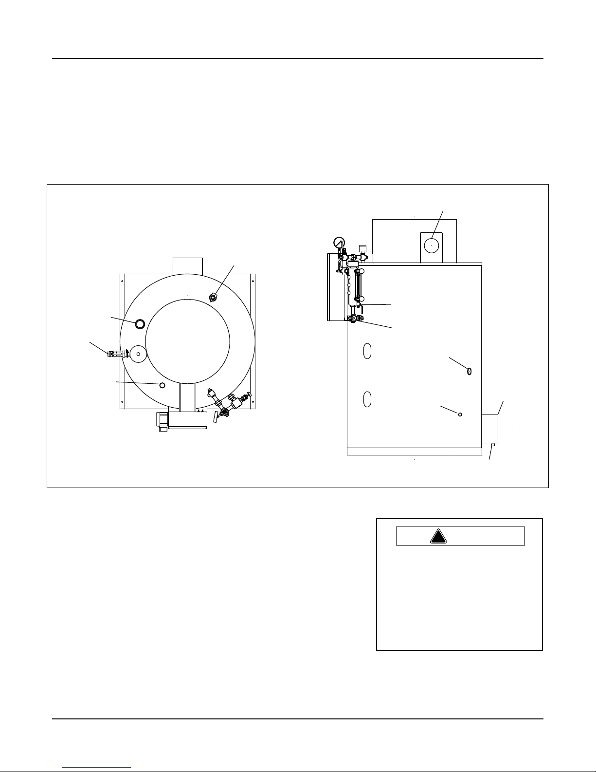
Do not attempt to place the boiler into service without verifying that all connections - fuel, steam and
water piping, electrical connections, stack, and combustion air provisions - have been installed properly
and in accordance with any applicable codes or regulations.
COMBUSTION AIR INLET
RELIEF VALVE
STEAM
OUTLET
GAS SUPPLY
SURFACE
BLOWOFF
Figure 1 CFV Connections
1.1 Operating Conditions
• The installation site should be as free as possible from vibration,
dust, and corrosive media
• The controllers should be located as far as possible from sources of
electromagnetic fields, such as frequency converters or high-voltage
ignition transformers
• Control panel must be connected to earth ground. For electrical
wiring requirements, see wiring diagram provided with the boiler or
in the CFV manual.
GAUGE GLASS DRAIN
WATER COLUMN DRAIN
FEEDWATER
STACK
BLOWDOWN
!
CONDENSATE DRAIN
Warning
OUTLET
When using direct vent
combustion in cold climates,
special care must be taken to
observe combustion air
temperature limits. Failure to
follow this precaution may lead
to equipment damage or unsafe
operation.
Part No. 750-288 3
Page 4
CFV Startup Guide
Boiler room ambient conditions
Relative humidity
Ambient temperature range 0
Storage temperature range -20
Combustion air temperature 0
Specifications
Input power 115 VAC single phase 60Hz
Recommended operating steam
pressure
Gas pressure requirements See Table 1
< 85% non-condensing
o
C to 50 oC / 32oF to 122oF
o
C to 60 oC / -4oF to 140oF
o
C to 50 oC / 32oF to 122oF
75-135 psig
1.2 Gas Piping
A manually operated shut-off valve and pressure regulator are provided
as standard on the Model CFV boiler. It is recommended to install an
approved gas filter or strainer in the gas supply line to the boiler. Please
inquire with the local gas supply company.
The boiler shall be installed such that the gas ignition system
components are protected from water (dripping, spraying, etc.) during
appliance operation and service.
If building supply gas pressure is greater than 1 psig (27.8” WC), an
upstream regulator with overpressure protection and proper gas venting
will be required and must be piped to a safe point of discharge.
All gas piping and components to the boiler gas train connection must
comply with NFPA 54, local codes, and utility requirements as a
minimum. Only gas approved fittings, valves, or pipe should be used.
Standard industry practice for gas piping is normally Schedule 40
black iron pipe and fittings.
See Table 1 for CFV gas pressure requirements.
Table 1 CFV gas pressure requirements
Boiler HP Minimum pressure required
at gas train connection
9.5 7.2" w.c.
10 7.2" w.c.
15 7.3" w.c.
20 7.5" w.c.
25 7.7" w.c.
30 8.5" w.c.
40 11.0" w.c.
50 10.0" w.c.
60 10.0" w.c.
Max. pressure
28” w.c.
Note: To measure supply pressure
at the CFV gas valve, use the
test port on the valve inlet
flange (see below). Do not
use the leak test cocks to
measure gas pressure.
1.3 Flue Gas Connection
The flue gases from the ClearFire boiler are removed via a gas-tight, temperature and corrosion resistant flue
gas pipeline. Only flue gas systems approved and tested by the relevant region or province are to be connected
to the ClearFire boiler. Refer to flue piping manufacturer for proper installation and sealing instructions.
See also Chapter 3 in the CFV Operation and Maintenance manual.
4 Part No. 750-288
Page 5
CFV Startup Guide
1.4 Boiler Water-Side Connections
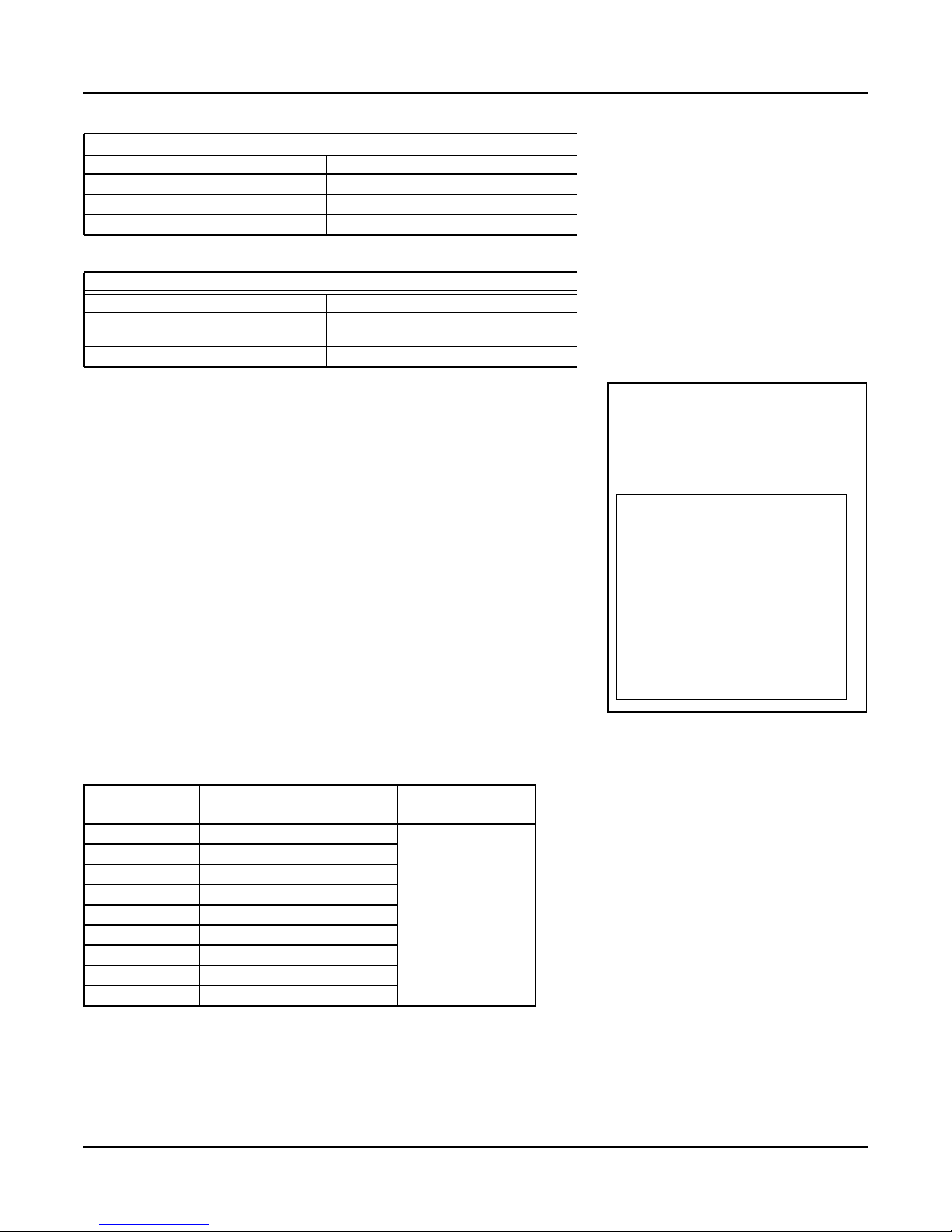
A pressure relief valve (safety valve; Figure 2), provided with the
boiler, must be installed in the mounting provided and piped to a safe
point of discharge. Use pipe sealing compound and a flat sided
wrench when securing the safety relief valve. Do not use a pipe
wrench and do not over tighten the relief valve. The safety valve must
be mounted in a vertical position so that discharge piping and coderequired drains can be properly piped to prevent buildup of back
pressure and accumulation of foreign material around the valve seat
area.
Connection to the main steam header is made at the nozzle projecting
upward from the boiler shell.
Feedwater is introduced through the piping assembly installed on the
side of the boiler vessel.
Figure 2 Pressure Relief Valve
Safety
Valve
1.5 Electrical Connections
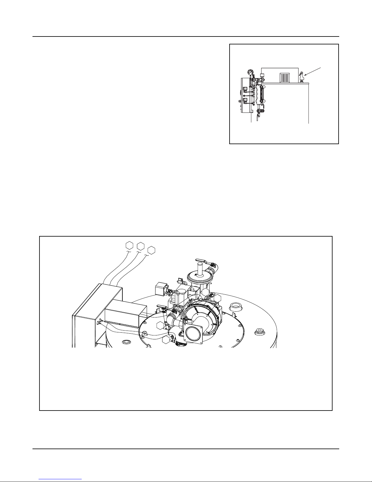
Refer to Figure 3 for CFV wiring and cable connections. See also wiring diagram on page 13.
A qualified electrician or service technician must make the electrical connections to the boiler; all local
electrical and building codes should be adhered to.
Refer to wiring diagram provided with the boiler or in the CFV manual. Ensure all required customer
connections are properly made. Main power (115 VAC single phase 60Hz) and any remote wiring should be
brought to the left side of the control panel and terminated at the appropriate terminals provided. Controls for
the boiler feed pump (or feedwater valve if applicable) should be wired to control panel terminals 6 and 7.
Figure 3 CFV wiring and cable connections
7
6
5
4
1
2
1. Connect UV Scanner to threaded connection on dry oven
2. Connect spark cables to dual electrode and ignition transformer
3. Plug AC pow er harnes s plug in to b lower
4. Plug D C blow er c ontrol harn es s pl ug in to blower
5. Connect incoming AC power per wiring diagram
6. Connect optional heat request inputs per wiring diagram
7. Connect pump controls per wiring diagram
The blower signal wiring must be isolated
from the blower power wiring and the
high voltage ignition cables.
3
Notice
Part No. 750-288 5
Page 6

CFV Startup Guide
1.6 Safety Controls
Users should take note of the safety controls installed as standard on the Model CFV. Minor adjustments to
the initial factory settings of some controls may be necessary for your particular installation.
It is required to test all controls for proper functioning prior to starting the boiler for the first time. Stepby-step procedures for testing the controls can be found in the CFV manual (Chapter 4 - Commissioning).
The primary flame safety control is the CB Falcon, which monitors the flame signal by means of an
ionization electrode installed in proximity to the burner canister.
Other Combustion Safety Controls (see Figure 4) include the following:
• Combustion Air Proving Switch
• Low Gas Pressure Switch
• High Gas Pressure Switch
• Dual Safety Shut-off Valve (SSOV)
Depress all manual reset buttons for all controls prior to starting the boiler.
Dual SSOV
Figure 4 Combustion Safety Controls at Burner
Warning
!
The Model CFV is factory tested. Nevertheless, all burner safety
controls should be checked upon installation, prior to initial firing.
Failure to verify burner control functioning could result in severe
bodily injury or death.
For detailed procedures on how to test the safety controls, see the
boiler Operation and Maintenance Manual.
Water Level Controls (see Figure 5)
The primary Low Water Cutoff and pump control level probes are mounted in an external water column.
The Auxiliary Low Water Cutoff is mounted in the boiler vessel or optional external column. Control boards
for the LWCO and ALWCO are located in the boiler control panel. The ALWCO includes a panel-mounted
reset/test switch.
6 Part No. 750-288
Page 7

CB FALCON
CONTROLLER
ALWCO CONTROLLER
Figure 5 Water level controls
Limit Controls (see Figure 6)
CFV Startup Guide
Control panel interior
LWCO CONTROLLER / PUMP CONTROL
The operating and high pressure limit controls are
externally mounted to the control trim piping. For
control settings and testing instructions, see the
boiler operation manual.
Figure 6 Limit Controls
1.7 Filling Boiler
Ensure that all feedwater equipment is properly installed and any feed
pumps, valves, etc. are in good working order.
Begin with the control panel DEMAND switch and CC/BLOWER switch (see
Figure 7) in the OFF position. Open the boiler vent valve (see Figure 8).
Turn the Control Circuit/Blower Switch ON to enable the feedwater control
circuit. If the CB Falcon icon does not appear on the display when the CC/
Blower switch is turned on, see STARTING THE BOILER below.
With the vent valve open, entrapped air will be allowed to escape while the
boiler fills with water. Do not close the vent valve until water is visible in
the gauge glass. The feed pump will shut off when water reaches the ‘Pump
Off’ probe level.
Check to ensure that no leaks appear at any pipe connections and correct
if water leaks are noticed.
Part No. 750-288 7
Figure 7 Control Panel Switches
Page 8

CFV Startup Guide
Important
!
The use of soft water is highly recommended. Failure to observe this recommendation can lead to dangerous
operating conditions, and may result in damage to the boiler. If necessary, your Cleaver-Brooks
representative can provide additional information regarding your water softening requirements.
Vent Valve
Gauge Glass
Figure 8 Filling the Boiler
2 - STARTING THE BOILER
Ensure boiler has been filled with water (see above - 1.7 Filling Boiler). The DEMAND switch should be in
the OFF position.
When the Control Circuit/Blower switch is turned ON, the Home page will appear on the CB Falcon display,
showing the boiler control icon. It may take a short time for the display/controller to initialize before the
Falcon icon appears.
If the Falcon icon does not appear, open the control panel and verify that the controller is receiving power.
The green ‘POWER’ LED should be lit (see Figure 9).
If the controller is powered on but still does not appear on the display, refer to manual. If unable to resolve
the problem, contact your CB representative.
Falcon
controller
icon
POWER
LED
HOME PAGE
Figure 9 Home Page; Falcon power indicator
8 Part No. 750-288
Page 9

CFV Startup Guide
2.1 Controller Configuration
The CB Falcon controller is factory pre-configured with default parameter
settings for the Model CFV. Prior to starting the boiler, verify that the
factory default settings are correct for your application. See the boiler
Note: The “Home” icon at the
upper left of the display
screen always returns to the
Home Page.
operation manual (Chapter 4 - Commissioning) for the parameter list and
parameter change procedure.
The “Back” icon at the upper
Changing the Setpoint
right displays the previous
screen.
The default steam pressure setpoint should be changed at this time to
suit your application. Press the CB Falcon icon on the Home page. The
Overview screen will appear. On the bottom row of screen buttons press
<Operation> to access the Operation screen (Figure 10).
Press the yellow highlighted setpoint display. A numeric keypad will appear. Press <Clear> to clear the
current value, enter the appropriate setting using the numeric keypad, and press <OK>.
Figure 10 Changing the setpoint
1
To change the steam pressure setpoint: 1. Press the yellow highlighted setpoint display window.
Note: Some features of the CB Falcon controls are password
protected. Service level password = 9220.
2.2 Initiating Burner Sequence
Before initial startup, check for blockages in the flue venting or vent terminations. Inspect the burner and furnace
for any contamination or blockages.
3
4
2. Clear the current value.
3. Enter the desired value.
4. Press <OK>.
Warning
!
2
When ready to start the boiler, navigate to the Operation screen (see “Changing the Setpoint” above).
Part No. 750-288 9
Page 10

CFV Startup Guide
BURNER
SWITCH
button
Figure 11 Operation screen
Turn the <Burner switch> screen button to ON. The burner is now
enabled.
Turn the control panel DEMAND switch to LOC (local). The burner
sequence should now begin. To verify that the sequence is in
Burner Sequence:
STANDBY (burner switch off or no demand)
SAFE STARTUP
progress, check the ‘Burner state’ display on the Operation screen.
If operating normally, the controller should advance through the
steps in the burner sequence (see Figure 12).
Note: The <Burner switch> screen button enables the burner, but
will not by itself start the lightoff sequence. In order for the burner
to start, the following must be true:
• <Burner switch> screen button is ON
• All control circuit interlocks are satisfied
• A demand for steam exists (example: DEMAND switch is on LOC
PREPURGE DRIVE TO PURGE (prove fan
purge rate)
PREPURGE MEASURED PURGE TIME
(30 sec default)
PREPURGE DRIVE TO LIGHTOFF (prove
lightoff rate)
PREIGNITION TEST
DIRECT BURNER IGNITION
and steam pressure is below setpoint)
Once started, the boiler will continue running until demand is met,
RUN (release to modulating control)
an alarm condition occurs, or until manually shut down.
Before leaving the boiler unattended, ensure all safety controls
Figure 12 Burner Sequence
have been checked and boiler operational settings are properly
set,
As part of the initial safety checks, a flame failure test should also be performed to verify that the controls
are able to respond properly to a loss of flame: Disconnect the flame rod cable and attempt to start the
burner. The CB Falcon should lock out, indicating Lockout 109 Ignition Failure. Reconnect flame rod cable
after test.
The CB Falcon requires a manual reset to resume operation after a lockout.
3 - MANUAL OPERATION
Certain circumstances - such as setting combustion - require operating the boiler in manual mode. To enter
manual mode, use the following procedure:
10 Part No. 750-288
Page 11

1.On the CB Falcon Operation screen, press the Firing Rate
display in the Modulation section.
2. A numeric keypad will appear, showing the current firing rate
and operating mode.*
3. Under Firing rate control select Manual in Run.
4. Press <Clear> to clear the current RPM value.
5. Enter the desired RPM setting using the numeric
keypad.
6. Press <OK>. The display will return to the Operation
screen and the burner will modulate to the chosen firing
rate.
*Use Manual in Run for normal manual operation. In Manual in Run
and Standby mode, the burner will not operate. Use this mode for
testing blower operation without firing the boiler.
Notice
CFV Startup Guide
Figure 13
The CFV has been factory tested at 1000’ ASL and tuned for 5-6% excess
O2. To ensure optimum combustion throughout the firing range, the O2%
should be verified and if necessary adjusted to the proper levels. This
procedure involves manually firing the burner while using a combustion
analyzer to monitor O2%. Low and high fire adjustments are made at the
main gas valve. See the CFV Operation and Maintenance manual for a
detailed procedure.
Note: If an alarm or lockout occurs
during startup or operation, see
the boiler Operation and
Maintenance manual.
If any of the following conditions occur:
• Loss of flame
• Excessive or unusual noise
• Flame appears irregular when viewed through sight glass
• Frequent low water shutdowns
Cease boiler operation. See the Troubleshooting section in the CFV manual or consult your authorized CB
representative.
Repeated nuisance low water shutdowns may indicate a problem with the boiler feed system and/or water
level controls.
4 - POST STARTUP
• Review Chapter 4 - Commissioning in the CFV manual. Ensure all safety checks have been performed
according to instructions.
• Set high gas pressure switch to 50% higher than operating gas pressure at low fire. Set low gas pressure
switch to 50% lower than operating gas pressure at low fire.
• Check the draft on the outlet stack and compare to acceptable limits (-0.25 to +0.25 inches WC).
Operating outside of acceptable limits could result in light off and flame failure problems.
• Verify gas pressure remains within limits shown in Table 1.
• A new boiler should be cleaned by boil-out prior to being placed into service. See Chapter 4 of the CFV
manual for boil-out procedure.
Part No. 750-288 11
Page 12

CFV Startup Guide
5 - LOCKOUTS, HOLDS, AND ALERTS
To assist in monitoring boiler operation, the CB Falcon control system employs messages of three types:
Lockouts, Holds, and Alerts.
• Lockouts and Holds indicate interruptions in boiler operation, whether occurring as part of the normal
operating sequence or due to an abnormal condition. Lockouts require a manual reset to continue operation,
while Holds do not. A Hold will automatically clear when the hold condition is removed or satisfied.
The most recent Lockouts are stored in CB Falcon memory and may be accessed through the Lockout
History. Holds are not logged in memory.
Note: Before attempting to restart the boiler after a Lockout, identify and correct the Lockout condition.
• Alerts indicate conditions or events which, while not preventing boiler operation, may nevertheless be of
interest in evaluating boiler performance or operating conditions. Examples include certain operator actions,
out-of-range configuration data, controller internal status reports (e.g. timers, counters, memory read/write
activity), and recycle events. Alerts require no operator acknowledgment and are for informational purposes
only.
The most recently occurring message (Lockout, Hold, or Alert) is displayed in the alarm banner on the
Overview screen (see Figure 14). Press this banner to access the Alert or Lockout History, where a list of
the most recently occurring Alerts/Lockouts can be viewed.
Alarm Banner
Figure 14 Alarm Banner
To obtain more information for a particular message, press that item in its respective history list. For Alerts,
burner cycle and hours of operation at the time of occurrence will be displayed. For Lockouts, in addition
to cycle and hours the screen will show on/off status of all interlocks at the time of the lockout. This
information can be used to help pinpoint the cause of a particular Lockout.
If the boiler is left unattended after a startup, the Alert/Lockout History can be consulted to determine
whether the boiler has been running normally or if operation has been interrupted due to a fault condition.
12 Part No. 750-288
Page 13

1
E
2
115V/1PH AC FUSED
POWER SUPPLY W/
GROUNDED NEUTRAL
BLOWER MOTOR FUSE SELECTION
CFV HP
10 - 30
40
50 - 60
3
CNTRL
CIRC
FUSE
50
DISPLAY
PS FUSE
1 AMP
LL1
57
N
BLOWER
FUSE
80
(8)
(L1)
(COM)
(6)
49
4
5
RESET
PB
(MOM)
ALWCO
(L2)
(7)
(NO)
(NC)
(G)
81
POWER
OFF
(REF. 8)
ON
4
LWCO DF16
PROBE
(A)
PROBES
(L1)
(COM)
54
55
(B)
(C)
56
(H)
(COM)
6 7
51
FW PUMP
4
RLY1
(LLCO)
(L)
RLY2
(NO)
(NC)
(G)
(NO)
(REF. 8)
13
4
(L2)
PS
(L)
(V+) (V-)
(N)
(G)
12 VDC
NOTES:
DASHED LINES INDICATE CUSTOMER CONNECTIONS
ALL CONTROL WIRE IS #18 AWG UNLESS OTHERWISE NOTED
DENOTES CONTROL PANEL TERMINAL
4
5
6
7
5 AMP
8
9
10
11
12
13
14
15
16
17
18
19
20
21
22
23
24
(REF. 8)
25
26
27
28
29
30
Figure 15 CFV Wiring Diagram
BLOWER MODEL RATING, CLASS CC
G1G170-AB05-20 6 A
G3G200-GN26-01 12 A
G3G250-GN39-01 15 A
4
W
W
(REF. 8)
(3)
R
R
3
B/R
B/R
(4)
HGPS
9
PR BL BL
(2)
MODBUS RS485 J3-MB2 - A,B,C
MR
(REF. 15)
OLC
(REF. 15)
HLC
8
(1)
MR
14
CUSTOMER CONNECTIONS:
FW PUMP ON/OFF 6 & 7
REMOTE ALARM 15 & 16
REMOTE ON-OFF 24 & 25
REMOTE 4-20MA INPUT 26 & 27
(2)
REMOTE
ALARM
52
53
GAS
VALVE
(1)
10
8
CFV Startup Guide
IGNITION
TRANSFORMER
2
BL
(REF. 14)
IONIZATION
ELECTRODE
C1
1
2
3
4
5
6
7
8
9
10
11
12
1
2
3
4
5
6
7
1
2
3
4
5
6
7
8
1
2
3
4
5
6
7
1
26,27,
BURNER
CANISTER
GROUND
TRANSFORMER
5
BK
(REF. 9)
(R)
24
23
BK
(V-) (V+)
BR
(REF. 25)
24 25
(REF. 7)
IGNITION
ELECTRODES
W
(C)
24 VAC
-
PRESS
XMTR
+
+
26
REMOTE ON-OFF
(24V 1A)
(REF. 8)
REM
AC POWER
CONNECTOR
G
G
W
1
BK
G
G
LGPS
BK
MR
16
CAPS
OR
GY
(REF. 15)
8
9
(REF. 15)
10
11
3C 18AWG
SHIELDED
14 GAUGE
2
3
11
15
12
N
L
RED
+-
Y
LOCAL
DISPLAY
BLOWER
12
11
10
9
8
7
6
5
4
3
2
1
7
6
5
4
3
2
1
8
7
6
5
4
3
2
1
7
6
5
4
3
2
1
9
ACB
MB1
BLK
G
DC CONTROL
CONNECTOR
G
G
J4
C2
J2
J1
J8
FALCON
J5
EXT IGN
FUEL VALVE
INTLK
J6
ALARM
PRE-IGN INTLK
LCI
ANNUN #1/IAS
ANNUN #2/LWCO
J7
ANNUN #3/ALWCO
ANNUN #4/HLC
ANNUN #5/HGPS
ANNUN #6/LGPS
J3
ACB
WH
J9
J10
J11
COMMS
MB2
COMMON
DATA DATA +
GLOBAL MODBUS
CONNECTIONS
TERMINALS: LL1,N,G,1,2,3,4-4-4,5-5-5,6,7,8,9,10,11,12,13,14,15,16,
23,24,25,
4
DEMAND
OFF
W
LOC
REMOT
4-20MA
27
4
(REF. 8)
25
-
(REF. 8)
CFV STEAM
Part No. 750-288 13
Page 14

CFV Startup Guide
14 Part No. 750-288
Page 15

CFV Startup Guide
Part No. 750-288 15
Page 16

e-mail: info@cleaverbrooks.com
Web Address: http://www.cleaverbrooks.com
 Loading...