

Cleaver-Brooks ClearFire CFLC-12000, ClearFire CFLC-4000, ClearFire CFLC-6000, ClearFire CFLC-8000, ClearFire CFLC Operation And Maintenance Manual
...Page 1
Model CFLC
ClearFire
Condensing Boiler
4,000 - 12,000 MBTU
Operation and Maintenance Manual
750-363
08/2017
Page 2
!
WARNING
DANGER
If the information in this manual is not followed exactly, a fire or explosion may result causing property damage, personal
injury or loss of life.
— Do not store or use gasoline or other
flammable vapors and liquids in the vicinity of this or any other appliance.
!
WARNING
DANGER
Improper installation, adjustment, service, or maintenance can cause equipment damage, personal injury, or death.
Refer to the Operation and Maintenance
manual provided with the boiler. Installation and service must be performed by a
qualified Cleaver-Brooks service provid-
— WHAT TO DO IF YOU SMELL GAS
• Do not try to light any appliance.
• Do not touch any electrical switch; do not use
any phone in your building.
• Immediately call your gas supplier from a
neighbor's phone. Follow the gas supplier's
instructions.
• If you cannot reach your gas supplier, call the
fire department.
— Installation and service must be performed by
a qualified Cleaver-Brooks, service agency or the
gas supplier.
!
WARNING
DANGER
To minimize the possibility of serious personal injury, fire or damage to the equipment, never violate the following safety rules.
— Always keep the area around the boiler free of
combustible materials, gasoline, and other flammable liquids and vapors
— Never cover the boiler, lean anything against it,
stand on it, or in any way block the flow of fresh
air to the boiler.
!
WARNING
DANGER
Be sure the fuel supply which the boiler
was designed to operate on is the same
type as specified on the boiler name
plate.
!
WARNING
DANGER
Should overheating occur or the gas supply valve fail to shut off, do not turn off or
disconnect the electrical supply to the
boiler. Instead turn off the gas supply at a
location external to the boiler.
!
WARNING
DANGER
Do not use this boiler if any part has been under
water. Immediately call your Cleaver-Brooks service representative to inspect the boiler and to replace any part of the control system and any gas
control which has been under water.
Notice
Where required by the authority having jurisdiction, the installation must conform to the Standard
for Controls and Safety Devices for Automatically
Fired Boilers, ANSI/ASME CSD-1.
!
WARNING
DANGER
The boiler and its individual shutoff valve must be
disconnected from the gas supply piping system
during any pressure testing of that system at test
pressures in excess of 1/2 psi (3.5 kPa).
Notice
This manual must be maintained in legible condition and kept adjacent to the boiler or in a safe
place for future reference. Contact your local
Cleaver-Brooks representative if additional manuals are required.
!
WARNING
DANGER
The installation must conform to the requirements
of the authority having jurisdiction or, in the absence of such requirements, to UL 795 Commercial-Industrial Gas Heating Equipment and/or the
National Fuel Gas Code, ANSI Z223.1
ii
Page 3
CLEAVER-BROOKS
Model CFLC
ClearFire Packaged Boiler
Condensing Boiler
Operation and Maintenance Manual
Cleaver-Brooks 2017
Please direct purchase orders for replacement manuals to your local Cleaver-Brooks authorized representative.
Manual Part No. 750-363
08/2017
iii
Printed in U.S.A.
Page 4
!
WARNING
DANGER
DO NOT OPERATE, SERVICE, OR REPAIR THIS EQUIPMENT UNLESS YOU FULLY UNDERSTAND ALL
APPLICABLE SECTIONS OF THIS MANUAL.
DO NOT ALLOW OTHERS TO OPERA TE, SERVICE, OR REPAIR THIS EQUIPMENT UNLESS THEY FULL Y
UNDERSTAND ALL APPLICABLE SECTIONS OF THIS MANUAL.
FAILURE TO FOLLOW ALL APPLICABLE WARNINGS AND INSTRUCTIONS MAY RESULT IN SEVERE
PERSONAL INJURY OR DEATH.
TO: Owners, Operators and/or Maintenance Personnel
This operating manual presents information that will help to properly operate and care for the equipment. Study its contents carefully. The unit will provide good service and continued operation if proper operating and maintenance instructions are followed. No attempt should be made to operate the unit until the principles of operation and all of the
components are thoroughly understood. Failure to follow all applicable instructions and warnings may result in severe
personal injury or death.
It is the responsibility of the owner to train and advise not only his or her personnel, but the contractors' personnel who
are servicing, repairing or operating the equipment, in all safety aspects.
Cleaver-Brooks equipment is designed and engineered to give long life and excellent service on the job. The electrical
and mechanical devices supplied as part of the unit were chosen because of their known ability to perform; however,
proper operating techniques and maintenance procedures must be followed at all times. Although these components afford a high degree of protection and safety, operation of equipment is not to be considered free from all dangers and
hazards inherent in handling and firing of fuel.
Any “automatic” features included in the design do not relieve the attendant of any responsibility. Such features merely
free him of certain repetitive chores and give him more time to devote to the proper upkeep of equipment.
It is solely the operator’s responsibility to properly operate and maintain the equipment. No amount of written instructions
can replace intelligent thinking and reasoning and this manual is not intended to relieve the operating personnel of the
responsibility for proper operation. On the other hand, a thorough understanding of this manual is required before attempting to operate, maintain, service, or repair this equipment.
Because of state, local, or other applicable codes, there are a variety of electric controls and safety devices which vary
considerably from one boiler to another. This manual contains information designed to show how a basic burner operates.
Operating controls will normally function for long periods of time and we have found that some operators become lax in
their daily or monthly testing, assuming that normal operation will continue indefinitely. Malfunctions of controls lead to
uneconomical operation and damage and, in most cases, these conditions can be traced directly to carelessness and
deficiencies in testing and maintenance.
It is recommended that a boiler room log or record be maintained. Recording of daily, weekly, monthly and yearly maintenance activities and recording of any unusual operation will serve as a valuable guide to any necessary investigation.
Most instances of major boiler damage are the result of operation with low water. We cannot emphasize too strongly the
need for the operator to periodically check his low water controls and to follow good maintenance and testing practices.
Cross-connecting piping to low water devices must be internally inspected periodically to guard against any stoppages
which could obstruct the free flow of water to the low water devices. Float bowls of these controls must be inspected
frequently to check for the presence of foreign substances that would impede float ball movement.
The waterside condition of the pressure vessel is of extreme importance. Waterside surfaces should be inspected frequently to check for the presence of any mud, sludge, scale or corrosion.
It is essential to obtain the services of a qualified water treating company or a water consultant to recommend the proper
boiler water treating practices.
The operation of this equipment by the owner and his or her operating personnel must comply with all requirements or
regulations of his insurance company and/or other authority having jurisdiction. In the event of any conflict or inconsistency between such requirements and the warnings or instructions contained herein, please contact Cleaver-Brooks before proceeding.
iv
Page 5

TABLE OF CONTENTS
Section 1 Introduction
CFLC Features and Benefits . . . . . . . . . . . . . . . . . . . . . . . . . . . . . . . . . . . . . . . . . . . . . 1-2
Standard Equipment . . . . . . . . . . . . . . . . . . . . . . . . . . . . . . . . . . . . . . . . . . . . . . . . . . 1-2
Optional Equipment . . . . . . . . . . . . . . . . . . . . . . . . . . . . . . . . . . . . . . . . . . . . . . . . . . . 1-7
Section 2 Installation
Assembly . . . . . . . . . . . . . . . . . . . . . . . . . . . . . . . . . . . . . . . . . . . . . . . . . . . . . . . . . . 2-3
Boiler Room . . . . . . . . . . . . . . . . . . . . . . . . . . . . . . . . . . . . . . . . . . . . . . . . . . . . . . . . 2-5
Flue gas/combustion air . . . . . . . . . . . . . . . . . . . . . . . . . . . . . . . . . . . . . . . . . . . . . . . . 2-5
Water Treatment . . . . . . . . . . . . . . . . . . . . . . . . . . . . . . . . . . . . . . . . . . . . . . . . . . . . 2-5
Boiler flush . . . . . . . . . . . . . . . . . . . . . . . . . . . . . . . . . . . . . . . . . . . . . . . . . . . . . . . . . 2-6
Using glycol . . . . . . . . . . . . . . . . . . . . . . . . . . . . . . . . . . . . . . . . . . . . . . . . . . . . . . . . 2-6
Gas connections . . . . . . . . . . . . . . . . . . . . . . . . . . . . . . . . . . . . . . . . . . . . . . . . . . . . . 2-8
Boiler water piping. . . . . . . . . . . . . . . . . . . . . . . . . . . . . . . . . . . . . . . . . . . . . . . . . . . 2-14
Minimum boiler overpressure . . . . . . . . . . . . . . . . . . . . . . . . . . . . . . . . . . . . . . . . . . . 2-18
Condensate removal and treatment . . . . . . . . . . . . . . . . . . . . . . . . . . . . . . . . . . . . . . . 2-18
Electrical Connections . . . . . . . . . . . . . . . . . . . . . . . . . . . . . . . . . . . . . . . . . . . . . . . . 2-21
Wiring diagram . . . . . . . . . . . . . . . . . . . . . . . . . . . . . . . . . . . . . . . . . . . . . . . . . . . . . 2-23
Section 3 Stack and Intake Vent Sizing and Installation
Venting Connections - General . . . . . . . . . . . . . . . . . . . . . . . . . . . . . . . . . . . . . . . . . . . 3-2
Vertical Venting / Inside Combustion Air . . . . . . . . . . . . . . . . . . . . . . . . . . . . . . . . . . . . 3-6
Vertical Venting / Direct Vent or Sealed Combustion Air . . . . . . . . . . . . . . . . . . . . . . . . . . 3-7
Venting for Multiple Units . . . . . . . . . . . . . . . . . . . . . . . . . . . . . . . . . . . . . . . . . . . . . . . 3-8
Combustion Air / Boiler Room Ventilation Requirements. . . . . . . . . . . . . . . . . . . . . . . . . 3-10
Section 4 Commissioning
Operating Conditions . . . . . . . . . . . . . . . . . . . . . . . . . . . . . . . . . . . . . . . . . . . . . . . . . . 4-2
Filling Boiler . . . . . . . . . . . . . . . . . . . . . . . . . . . . . . . . . . . . . . . . . . . . . . . . . . . . . . . 4-2
Control Setpoints . . . . . . . . . . . . . . . . . . . . . . . . . . . . . . . . . . . . . . . . . . . . . . . . . . . . 4-2
Model CFLC Boiler / Burner Controller . . . . . . . . . . . . . . . . . . . . . . . . . . . . . . . . . . . . . . 4-3
Falcon Display/Operator Interface . . . . . . . . . . . . . . . . . . . . . . . . . . . . . . . . . . . . . . . . . 4-4
Controller Configuration . . . . . . . . . . . . . . . . . . . . . . . . . . . . . . . . . . . . . . . . . . . . . . . . 4-7
Variable Speed Drive Settings . . . . . . . . . . . . . . . . . . . . . . . . . . . . . . . . . . . . . . . . . . . . 4-9
Burner Sequence . . . . . . . . . . . . . . . . . . . . . . . . . . . . . . . . . . . . . . . . . . . . . . . . . . . 4-10
Fan Speed Settings . . . . . . . . . . . . . . . . . . . . . . . . . . . . . . . . . . . . . . . . . . . . . . . . . . 4-10
Initial Start-up Procedure . . . . . . . . . . . . . . . . . . . . . . . . . . . . . . . . . . . . . . . . . . . . . . 4-10
Post Start-up Checkout Procedure . . . . . . . . . . . . . . . . . . . . . . . . . . . . . . . . . . . . . . . 4-17
Falcon Control Functions and Customer Interface . . . . . . . . . . . . . . . . . . . . . . . . . . . . . 4-18
Section 5 Service and Maintenance
Disassembly for Inspection . . . . . . . . . . . . . . . . . . . . . . . . . . . . . . . . . . . . . . . . . . . . . . 5-2
Reassembly . . . . . . . . . . . . . . . . . . . . . . . . . . . . . . . . . . . . . . . . . . . . . . . . . . . . . . . . 5-4
Ignition and Flame Detection Systems . . . . . . . . . . . . . . . . . . . . . . . . . . . . . . . . . . . . . . 5-4
Troubleshooting . . . . . . . . . . . . . . . . . . . . . . . . . . . . . . . . . . . . . . . . . . . . . . . . . . . . . 5-6
Extended Shutdown . . . . . . . . . . . . . . . . . . . . . . . . . . . . . . . . . . . . . . . . . . . . . . . . . . . 5-8
Emergency Shutdown. . . . . . . . . . . . . . . . . . . . . . . . . . . . . . . . . . . . . . . . . . . . . . . . . . 5-8
Section 6 Parts
Recommended Spare Parts List Model CFLC ................................................................... 6-2
Boiler Mechanical Assembly........................................................................................... 6-3
Burner Assembly .........................................................................................................6-7
UV Scanner ................................................................................................................. 6-9
Gas Train .................................................................................................................. 6-10
Dual Fuel Gas Trains .................................................................................................. 6-18
Pilot Gas Train ..........................................................................................................6-21
Control Panel ............................................................................................................6-22
Cables and Cable Harness ..........................................................................................6-23
Optional Parts ........................................................................................................... 6-24
Casing & Insulation ..................................................................................................... 6-25
Appendix A - Falcon Parameters
Appendix B - VSD Parameters
Appendix C - Gas Valve
Appendix D - Falcon Alert, Hold, and Lockout Codes
Appendix E - Falcon Lead Lag
Appendix F - Falcon Program Module
v
Page 6

vi
Page 7

Section 1
Introduction
CFLC Features and Benefits . . . . . . . . . . . . . . . . . . . . . . . . . . . . . . . 1-2
Standard Equipment . . . . . . . . . . . . . . . . . . . . . . . . . . . . . . . . . . . . 1-2
Optional Equipment . . . . . . . . . . . . . . . . . . . . . . . . . . . . . . . . . . . . . 1-7
www.cleaverbrooks.com
Page 8

Section 1 — Introduction
1.1 CFLC FEATURES AND BENEFITS
Compact Firetube Design
The CFLC boiler is a two pass horizontally fired durable Firetube boiler. The extended heating surface tubes
provide for very high levels of performance in a compact space. The boiler is designed to fire natural gas.
High Efficiency
With the extended heating surface tubes the boiler can produce fuel to water efficiency of up to 99%
depending upon operating conditions.
Advanced Construction
Constructed to ASME standards, the CFLC Boiler will provide many years of trouble free service.
First pass tubes are made from SA178A Carbon Steel and are of rifle design for maximum heat transfer.
Second pass tubes are made from UNS S32101 Duplex Stainless Steel with AluFer extended heating
surface inserts for maximum heat transfer.
Dual Temperature Return
Two return pipes - high and low temperature - allow condensing performance with as little as 10% return
water at condensing temperature.
Ease of Maintenance
The steel enclosures are readily removable for access to all key components. A hinged burner provides
access for burner maintenance and fireside inspection.
Quality Construction
ASME construction ensures high quality design, safety, and reliability.
ISO 9001 certified manufacturing process ensures the highest degree of manufacturing standards is always
followed.
Full Modulation
The burner and combustion fan modulate to provide only the amount of heat required, providing quiet and
efficient operation under all conditions.
Premix Technology
The CFLC boiler utilizes "Premix" technology to mix both fuel and combustion air prior to entering the firing
chamber. This technology provides clean, efficient combustion with very low emission levels.
Designed For Heating Applications
The pressure vessel is constructed of durable ASTM Grade Steel and Stainless Steel materials to provide
many years of operating life.
Thermal shock resistant design with large water volume and low pressure drop is ideal for primary variable
flow applications.
1.2 STANDARD EQUIPMENT
1.2.1. The Boiler
The boiler is designed for a Maximum Allowable Working Pressure (MAWP) of 160 psig (11 Bar) in
accordance with the ASME Code for Low Pressure Section IV Hot Water Boilers and is stamped accordingly.
Operating pressure shall be less than 144 psig (9.9 Bar).
The vessel is mounted on a steel base with insulation & casing provided including trim and controls. Trim
and controls include safety relief valve, pressure and temperature gauges, probe type low water control, and
Falcon hydronic boiler control with associated sensors.
1-2 Part No. 750-363
Page 9
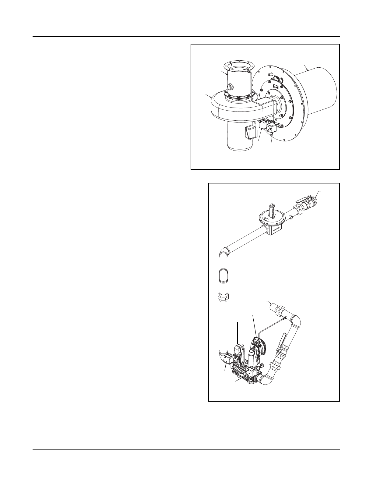
1.2.2. The Burner
The burner utilizes a premix venturi, self-regulating
fuel train, variable speed blower modulation, and
Fecralloy metal fiber burner head.
Modulating combustion air fan provides 5:1
turndown.
Combustion canister of the burner is constructed of a
Fecralloy-metal fiber for solid body radiation of the
burner flame, which provides low emissions.
At maximum firing rate, the sound level of the burner
is less than 85 dBA, measured in front of the boiler at
a distance of 3 feet.
Room air for combustion is standard (combustion air
filter provided).
A direct vent combustion air adapter kit is available.
Refer to Installation and Parts sections in this manual
for options and details.
VENTURI
BLOWER
ASSEMBLY
Section 1 — Introduction
BURNER CANISTER
HAPS
CAPS
Figure 1-1 Burner Assembly
1.2.3. Burner Gas Train
The gas train assembly is provided in accordance with UL
certification and complies with ASME CSD-1. The gas train
assembly is factory assembled and wired, consisting of the
following components:
A. Low Gas Pressure Switch - manual reset
B. High Gas Pressure Switch - manual reset
C. Single body, dual safety motorized shut-off valves
with POC and regulating actuator
D. Manual Shutoff Butterball Valve
E. Regulator (optional, based on gas supply pressure)
F. Test cocks
1.2.4. Controls
The Falcon hydronic control is an integrated burner
management and modulation control with a touch-screen
display/operator interface.
The controller is capable of the following functions:
• Two (2) heating loops with PID load control.
• Burner sequencing with safe start check, pre-purge, pilot
ignition, and post purge.
• Electronic ignition.
• Flame Supervision.
• Safety shutdown with time-stamped display of lockout
condition.
• Variable speed control of the combustion fan.
• Supervision of low and high gas pressure, air proving, stack
back pressure, high limit, and low water.
• First-out annunciator.
• Real-time data trending.
• (3) pump/auxiliary relay outputs.
• Modbus communication capability.
• Outdoor temperature reset.
• Remote firing rate or setpoint control
• Setback/time-of-day setpoint
• Lead/Lag for up to 8 boilers
E
GAS INLET
F
TO VENTURI
C
D
E
A
B
Figure 1-2 Gas Train (8000 shown)
Part No. 750-363 1-3
Page 10
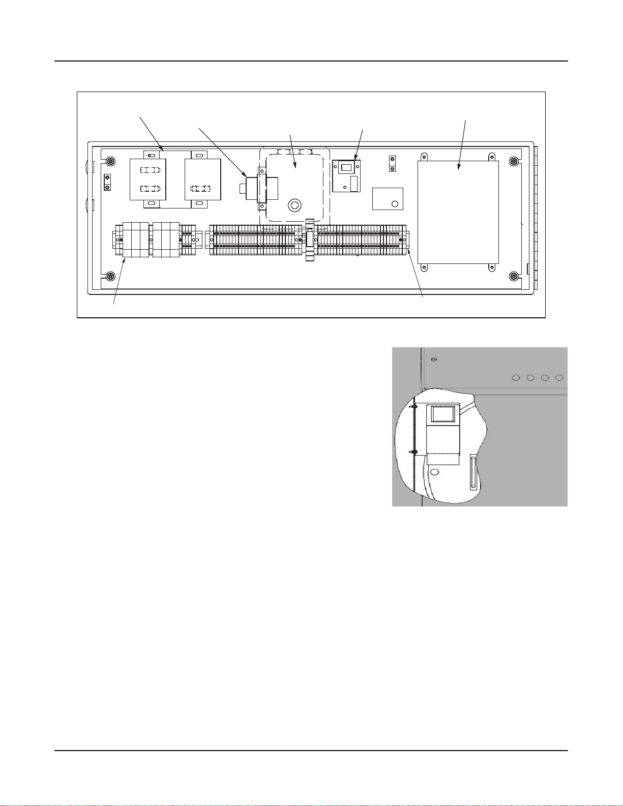
Section 1 — Introduction
TRANSFORMER, 460/230/208V PRI, 115 V SECONDARY,
350VA, FUSED TOP
TRANSFORMER, 115v/25v
IGNITION TRANSFORMER
(FAR SIDE)
WATER LEVEL
CONTROL - LWCO
FALCON CONTROLLER, HYDRONIC
FUSE, 9 AMP
Figure 1-3 Control panel interior
1.2.5. Variable Speed Drive
Modulating combustion air fan speed is controlled by a Variable
Speed Drive mounted inside the front casing below the Falcon control
panel.
1.2.6. Component/Connection Locations
Figure 1-5 shows the CFLC component orientation and heat flow
path. The return water connections are at the lower vessel and the
hot water outlet is at the top of the boiler.
Figure 1-6 shows the locations of the safety valve and air vent
connections. Figure 1-7 shows the location of the return water
temperature sensor.
The stack is connected on the right side of the boiler when facing the
front. The flue gas duct sizes may be reduced at the vent connection.
See also Section 3,
Stack and Intake Vent Sizing and Installation.
TERMINAL TRACK
Figure 1-4 VSD (cutaway view)
1-4 Part No. 750-363
Page 11
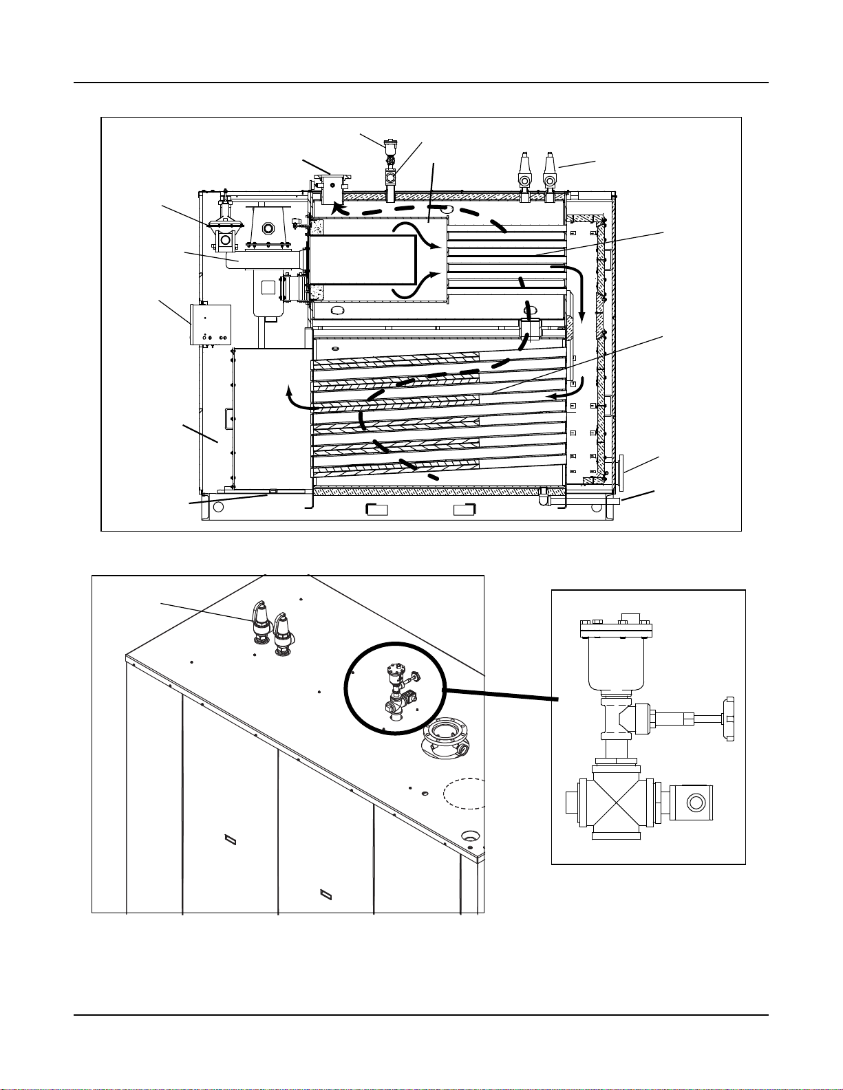
Section 1 — Introduction
Gas Train
Burner
Assembly
Control Panel
Flue/
condensate
collection
chamber
Condensate
drain
Air Vent (optional)
Water Outlet
TO STACK
Combustion
gas flow
LWCO probe holder
Furnace
Water circulation
Safety Valve(s)
EX Tubes
Alufer Tubes
Water
Return (2)
Boiler Drain
SAFETY VALVE(S)
Figure 1-5 CFLC Cutaway
AUTO AIR VENT
(OPTIONAL)
GATE VALVE
LWCO PROBE
HOLDER
Figure 1-6 Boiler safety valve(s) & air vent
Part No. 750-363 1-5
Page 12
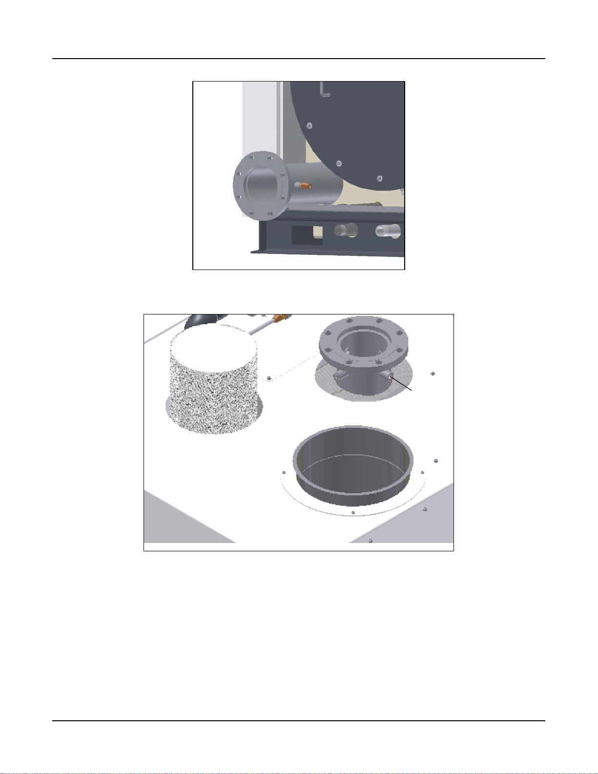
Section 1 — Introduction
Figure 1-7 Return temperature sensor (rear casing & insulation not shown)
WATER
OUTLET
OUTLET TEMP.
sensor well
COMBUSTION AIR FILTER
STACK OUTLET
Figure 1-8 Stack Outlet, Water Outlet, and Combustion Air Inlet
1-6 Part No. 750-363
Page 13

Section 1 — Introduction
1.3 OPTIONAL EQUIPMENT
Certain project-specific options may have been supplied with the boiler if these options were specified at
the time of order entry. In addition, some options may have been provided (by others) that are not part of
Cleaver-Brooks’ scope of supply. In either case, the Cleaver-Brooks authorized representative should be
consulted for project specifics.
These are the options that are available for the CFLC boiler from Cleaver-Brooks:
A. Condensate neutralization tank assembly - consists of neutralizing media, filter, and PVC
condensate holding tank. This assembly is further described in Chapter 2.
B. Direct vent combustion air adapter kit
C. Outdoor temperature sensor for outdoor reset, frost protection, and warm weather shutdown
D. Header temperature sensor for multiple boiler Lead/Lag operation
E. Alarm Horn for safety shutdown
F. Relays for output signal for burner on, fuel valve open
G. Stack Thermometer
H. Stack temperature limit-sensor
I. Auto air vent
J. Boiler drain valve
K. Gas pressure relief valve
L. Gas pressure gauge
M. Water isolation valves
N. Hydronic circulating pumps
O. Seismic anchoring provisions
For options not listed, consult your authorized CB representative.
Part No. 750-363 1-7
Page 14

Section 1 — Introduction
1-8 Part No. 750-363
Page 15
Section 2
Installation
Assembly . . . . . . . . . . . . . . . . . . . . . . . . . . . . . . . . . . . . . . . . . . . . 2-3
Boiler Room . . . . . . . . . . . . . . . . . . . . . . . . . . . . . . . . . . . . . . . . . . 2-5
Flue gas / combustion air . . . . . . . . . . . . . . . . . . . . . . . . . . . . . . . . . 2-5
Water treatment . . . . . . . . . . . . . . . . . . . . . . . . . . . . . . . . . . . . . . . 2-5
Boiler flush . . . . . . . . . . . . . . . . . . . . . . . . . . . . . . . . . . . . . . . . . . . 2-6
Using glycol . . . . . . . . . . . . . . . . . . . . . . . . . . . . . . . . . . . . . . . . . . 2-6
Gas connections . . . . . . . . . . . . . . . . . . . . . . . . . . . . . . . . . . . . . . . 2-8
Boiler water piping . . . . . . . . . . . . . . . . . . . . . . . . . . . . . . . . . . . . . 2-14
Minimum boiler overpressure . . . . . . . . . . . . . . . . . . . . . . . . . . . . . . 2-18
Condensate removal and treatment . . . . . . . . . . . . . . . . . . . . . . . . . 2-18
Electrical connections . . . . . . . . . . . . . . . . . . . . . . . . . . . . . . . . . . 2-21
Wiring diagram . . . . . . . . . . . . . . . . . . . . . . . . . . . . . . . . . . . . . . . 2-23
Warning
!
Provisions for combustion and ventilation air must
be in accordance with the National Fuel Gas
Code, ANSI Z223.1, or the CAN/CSA B149
Installation Codes, or applicable provisions of the
local building codes. Failure to follow this warning
could result in personal injury or death.
Caution
The boiler must be installed such that the gas
ignition system components are protected from
water (dripping, spraying, rain, etc.) during
appliance operation and sevice. Failure to follow
this warning could result in equipment failure.
Warning
!
If an external electrical source is utilized, the boiler
when installed must be electrically bonded to
ground in accordance with the requirements of the
authority having jurisdiction, or in the absence of
such requirements with the National Electrical
Code ANSI/NFPA 70 and/or the Canadian
Electrical Code Part I CSA C22.1.
www.cleaverbrooks.com
Warning
!
The installation must conform to the requirements of the authority having jurisdiction, or in
the absence of such requirements, to the
National Fuel Gas Code, ANSI Z223.1 and/or
CAN/CSA B149 Installation Codes.
Page 16

Section 2 — Installation
2-2 Part No. 750-363
Page 17
Section 2 — Installation
2.1 BOILER ASSEMBLY AND PLACEMENT
2.1.1 Packaging
The Cleaver-Brooks Model CFLC boiler is shipped fully assembled, ready for installation.
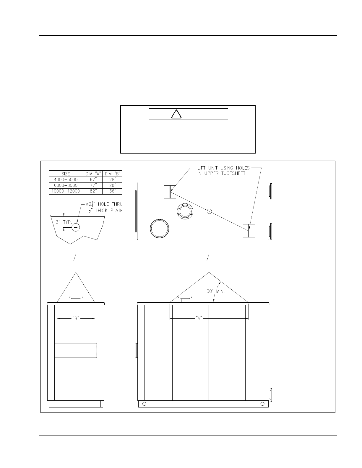
2.1.2 Lifting and moving the boiler
The Model CFLC boiler is lifted by means of the holes provided in the upper tube sheets. See rigging diagram
below.
Caution
!
In order to avoid damage to the unit, lifting or
moving the boiler should only be done by
experienced personnel suitably equipped for
moving heavy equipment.
Figure 2-1 CFLC Rigging
Note: The boiler
should not be moved
by pushing, prying, or
pulling on any part of
the casing.
Part No. 750-363 2-3
Page 18
Section 2 — Installation
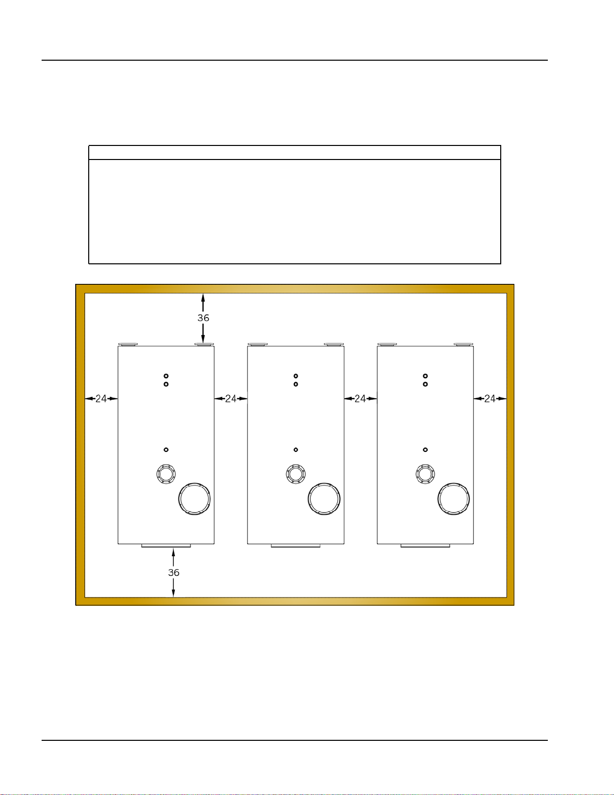
2.1.3 Boiler placement
The boiler or boilers should be mounted in accordance with Figure 2-2 below. Required front, rear, and side
clearances are shown. Under special circumstances, reduced side clearance between boilers may be
feasible. Contact your C-B authorized representative for assistance.
NOTE
The boiler assemblies are intended for installation in accordance with the appropriate
standards of the National Fire Protection Association and the building code recommended
by the American Insurance Association. Local codes may differ. Installation should provide
clearances to unprotected combustible material not less than those indicated in the
following:
Clearances to adjacent combustible construction not less than 36 inches from control
panel front, 24 inches from sides, and 36 inches above and rear. The floor beneath these
units may be combustible. In all cases, the flue pipe shall not pass through any floor or
ceiling or any combustible wall or partition unless suitably guarded.
Top Clearance = 36”
Figure 2-2 Clearance Required (inches)
2-4 Part No. 750-363
Page 19
Section 2 — Installation
2.2 BOILER ROOM
The boiler room must comply with all building codes and regulations. An adequate supply of combustion
air is required for safe operation. If the optional sealed combustion/direct vent kit is used, ventilation must
be provided to meet applicable regulations for air supply.
Note: For further details on sealed combustion/direct vent kits, see Section 3, Stack and Intake Vent Sizing
and Installation and Section 6, Parts.
Clean combustion air is required for optimum efficiency and boiler operation. Dust and airborne
contaminants will adversely effect burner performance. An air filter is included to keep airborne
contamination from the burner.
If using sealed combustion/direct venting, the air intake should be positioned to keep rain or snow from
entering the intake piping.
The boiler must be installed so that the gas ignition system components are protected from water (dripping,
spraying, etc.) during appliance operation and service.
2.3 FLUE GAS / COMBUSTION AIR
The flue gases from the Model CFLC boiler should be removed via a gas-tight, temperature and corrosion
resistant flue gas pipeline. Only flue gas systems approved and tested by the relevant region or province are
to be connected to the boiler. Refer to flue piping manufacturer for proper installation and sealing
instructions. See also Chapter 3 of this manual for combustion air and flue gas venting requirements.
Table 2-1. Boiler room environmental limits
Maximum temperature 122 deg F
Minimum temperature 32 deg F
Humidity 90% RH non condensing
Warning
!
The boiler must not be installed on carpeting.
2.4 WATER TREATMENT
Cleaver-Brooks ClearFire condensing boilers are suitable for heating systems without significant oxygenation
capacity. Systems with continuous oxygenation capacity due to unknown or unseen leaks must be equipped
with a system separation or pretreatment device. Closed loop hydronic systems should incorporate air
separation, dirt elimination, and air venting.
Clean, soft water is generally the best heating medium for filling and make-up water in systems utilizing the
Model CFLC. If the water available from the main system is not suitable for use, then demineralization and/
or treatment with inhibitors is necessary. Treated filling and make-up water must be checked at least once
a year or more frequently if so specified in the application guidelines from the inhibitor manufacturer.
Those parts of the boiler in contact with water are manufactured with both ferrous materials and corrosionresistant stainless steel. The chloride content of the heating water should not exceed 30 ppm and the pH
level should be between 8.3 to 10.5 after six weeks of operation.
To maintain the boiler's efficiency and prevent overheating of the heating surfaces, the values in Table 2-2
should not be exceeded. Water make-up during the lifetime of the boiler should not be greater than 3 times
the system volume. A water meter should be installed on the makeup line to monitor makeup water volume.
Should the system require flushing or cleaning after installation of the CFLC, take care that no particulate
matter reaches the boiler during the cleaning process.
Part No. 750-363 2-5
Page 20
Section 2 — Installation
Note: Corrosion and sludge deposits in old systems must be removed
prior to installation of a new boiler.
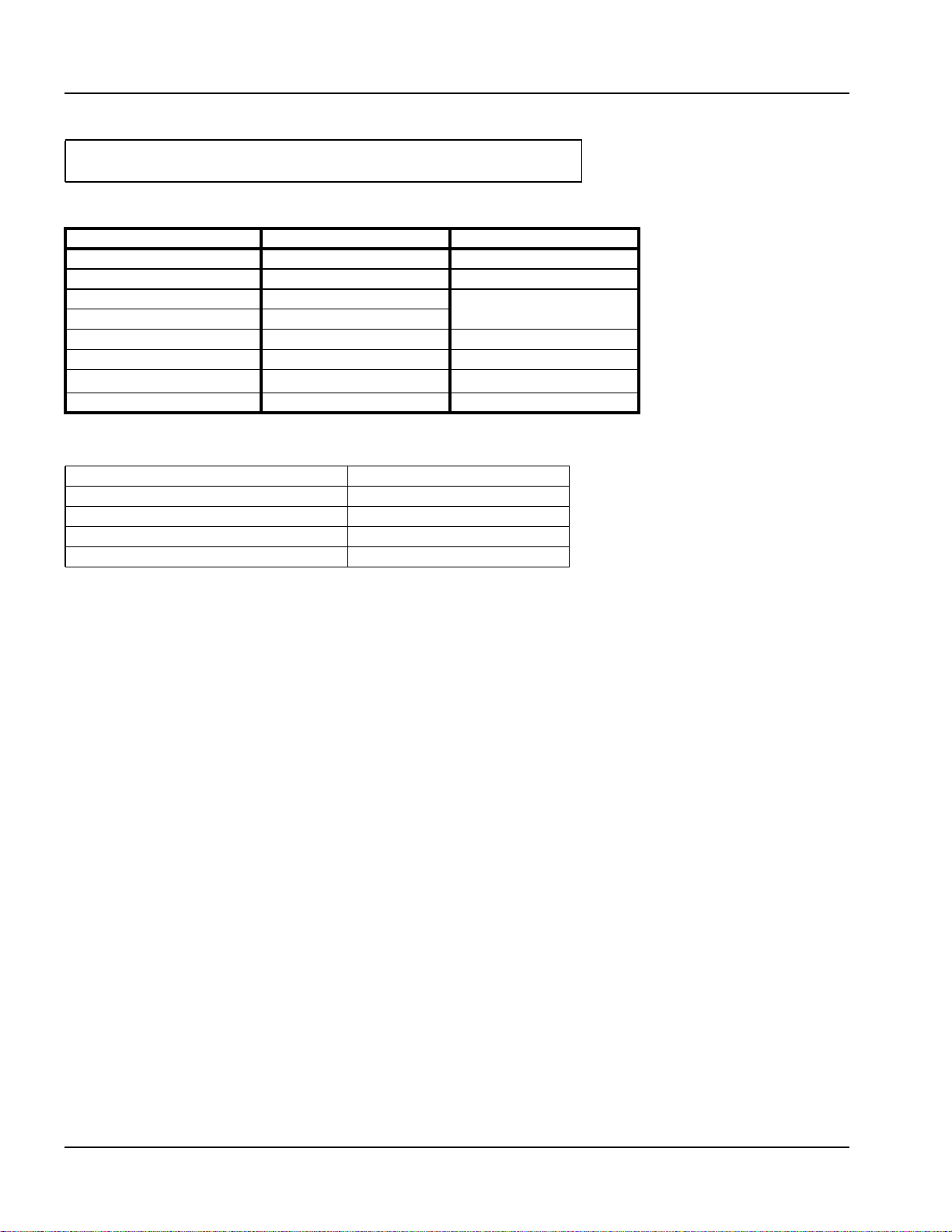
Table 2-2 Model CFLC Water Chemistry Requirements
Parameter Limit Means of control
Glycol 25-50% Glycol fill/mixing station
pH 8.3 - 10.5 Buffering agent
Nitrates 50 ppm
Sulfates 50 ppm
Chloride < 250 ppm
Oxygen < 0.1 ppm Air separator/eliminator
Specific Conductivity
< 3500 mmho/cm
Total Hardness < 10 ppm Softener
Table 2-3 Model CFLC Water Temperature Data (Non-Glycol)
Minimum inlet temp. 33
Maximum operating supply set point temp. 230
Maximum design temp. 250
Minimum supply set point temperature 130
Max allowable Delta T 100
Chemical additives
o
F
o
F
o
F
o
F
o
F
2.5 BOILER FLUSH
Cleaver-Brooks recommends cleaning in accordance with the recommendations of the boiler owner’s water treatment
company for each individual site. The boiler may be flushed with or without heat applied, as deemed appropriate by the
chemical treatment company. A traditional steam “Boil Out” is not required on Cleaver-Brooks hot water boilers.
Following are some general recommendations to help ensure long boiler life and efficient operation.
NOTE: these are recommendations only. The chemical treatment supplier should recommend a procedure based on
the site conditions and quality of water being used to fill the system.
If the entire system is being flushed THROUGH the boiler, weld slag and deposits from the piping system may settle in
the boiler. The boiler is typically a low velocity zone where these deposits tend to accumulate. The boiler should be
drained periodically during the flushing process to keep any deposit build up to a minimum. When the system flush is
complete, drain the boiler completely and open water side inspection ports for visual inspection. Any deposits should be
manually flushed out.
If the boiler is isolated during the system flush, or if this is an equipment replacement only where minimal amounts of
system piping have been replaced, there should be minimal manufacturing deposits inside the boiler and no boiler flush
is required.
To provide the longest life of the equipment it is recommended but not mandatory to chemically treat the boiler prior to
start-up. The owner’s water treatment company should determine needed course of action for each installation.
2.6 USING GLYCOL
The Model CFLC boiler may be operated with a solution of glycol and water. Where glycols are added, the
system must first be cleaned and flushed. Correct glycol selection and regular monitoring of the in-use
concentration and its stability is essential to ensure adequate, long-term freeze protection, including
protection from the effects of glycol-derived corrosion resulting from glycol degradation.
2-6 Part No. 750-363
Page 21
Section 2 — Installation
Typically, ethylene glycol is used for freeze protection, but other alternatives exist, such as propylene glycol.
Glycol reduces the water-side heat capacity (lower specific heat than 100% water) and can reduce the
effective heat transfer to the system. Because of this, design flow rates and pump selections should be sized
with this in mind.
Generally, corrosion inhibitors are added to glycol systems. However, all glycols tend to oxidize over time in
the presence of oxygen, and when heated, form aldehydes, acids, and other oxidation products. Whenever
inadequate levels of water treatment buffers and corrosion inhibitors are used, the resulting water glycol
mixture pH may be reduced to below 7.0 (frequently reaching 5) and acid corrosion results. Thus, when
pH levels drop below 7.0 due to glycol degradation the only alternative is to drain, flush, repassivate, and
refill with a new inhibited glycol solution.
The following recommendations should be adhered to in applying ClearFire model CFLC boilers to hydronic
systems using glycol:
1) Maximum allowable antifreeze proportion (% volume):
50% antifreeze (glycol)
50% water
2) Glycol minimum temperature rating 300 deg F (149 deg C).
3) Maximum allowable boiler outlet/supply temperature: 200 deg F (93 deg C).
4) Minimum water circulation through the boiler:
a) The minimum water circulation must be defined in such a way that the temperature difference between the boiler
outlet/supply and inlet/return is a maximum of 40 deg F (22 deg C), defined as DT (Delta T). A DT Limit algorithm
should be enabled in the boiler controller.
b) Independent from the hydraulics of the heating system, regular water circulation through each boiler is required
while the boiler is operating (requires a dedicated boiler pump if in a primary/secondary loop arrangement). Refer
to table below for minimum boiler circulation rates.
5) Minimum over-pressure at the boiler:
For outlet temperatures up to the maximum of 200 deg F (93 deg C), a minimum operating pressure of 30 psig (2.1 bar) is
required.
6) pH level should be maintained between 8.3 and 10.5
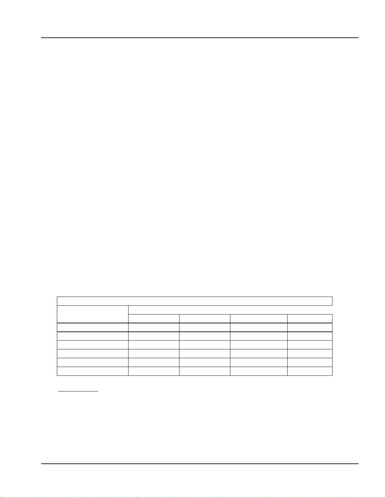
Table 2-4 Glycol Application Guidelines — ClearFire Model CFLC
Minimum required boiler circulation rate (gpm) at maximum firing rate
ClearFire
Model-Size
CFLC-4000
CFLC-5000
CFLC-6000
CFLC-8000
CFLC-10000
CFLC-12000
Notes/Limitations:
1. Glycol concentration limit of 25%-50%. Minimum required system operating pressure is 30 psig.
2. Maximum system operating temperature of 200 ˚F. Maximum ΔT of 40˚.
3. Circulation rates correlate with boiler output based on 92% nominal efficiency.
4. Standard altitude (<2000' ASL). Contact C-B for high altitude applications.
5. Pumps should be sized based on system design ΔT and minimum required flow rates.
6. At minimum firing rate, the minimum circulation rate should correspond to the boiler's turndown.
ΔT = 10˚ ΔT = 20˚ ΔT = 30˚ ΔT = 40˚
813 407 271 203
1016 508 339 254
1220 610 374 281
1626 813 499 368
2033 1016 624 468
2439 1220 749 562
System ΔT (˚F)
Part No. 750-363 2-7
Page 22
Section 2 — Installation
2.7 GAS CONNECTIONS
2.7.1 General
The ClearFire Model CFLC gas fired condensing boilers use full modulating burners that require appropriate
gas supply pressure and volume for proper operation. The gas requirements specified in this section must
be satisfied to ensure efficient and stable combustion. Installation must follow these guidelines and those
of any local authorities having installation jurisdiction.
2.7.2 Gas Train Components
CFLC boilers are equipped with a gas train that meets the requirements of ASME CSD-1, FM and XL-GAP
(formerly IRI). The gas train and its components have been designed and tested to operate for the highest
combustion efficiency for the CFLC units.
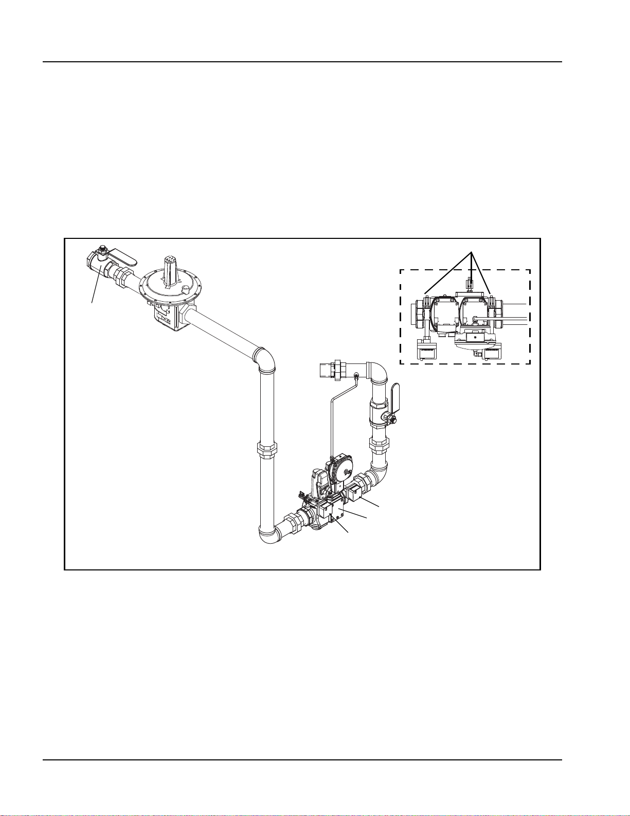
Leak test cocks
Manual
shutoff valve
(MSOV)
High pressure
regulator (optional)
Gas valve, top view
Low gas press. switch
Figure 2-3 CFLC Gas Train (typical)
MSOV
High gas press. switch
Double-body gas valve
2-8 Part No. 750-363
Page 23
Section 2 — Installation
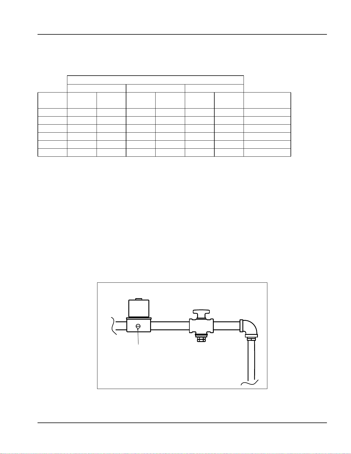
2.7.3 Gas Pressure Requirements
For proper and safe operation, each CFLC Series boiler requires a stable gas supply pressure. See table
below for pressure requirements. Refer also to
Table 2-5 CFLC gas pressure requirements
Gas Supply Pressure (at gas regulator outlet)
Natural Gas 20ppm Natural Gas 9ppm Propane
Boiler
size
4000 9 14 10 14 9 14 3-5
5000 9 14 10 14 9 14 3-5
6000 35 56 35 56 31 56 3-5
8000 35 56 42 56 31 56 3-5
10000 38 56 38 56 35 56 3-5
12000 38 56 40 56 35 56 3-5
Min
(“WC)
Max*
(“WC)
Min
(“WC)
*Listed max. pressures are without the use of a step-down regulator. The CFLC can accommodate higher
supply pressures with the addition of an upstream regulator:
CFLC 4000 - 5000 >1/2 psig requires step-down regulator
>5 psig requires overpressure protection
CFLC 6000 - 12000 >2 psig requires step-down regulator
>7 psig requires overpressure protection
When an upstream regulator is installed, required minimum pressures will be higher due to the pressure
drop across the regulator.
Actual gas pressure should be measured when the burner is firing using a manometer at the upstream test
port connection on the main gas valve. For a multiple unit installation, gas pressure should be set for a
single unit first, then the remaining units should be staged on to ensure that gas supply pressure drop is
not more than 7" w.c. and never below the required pressure. Fluctuating gas pressure readings could be
indicative of a faulty supply regulator or improper gas train piping to the boiler. Refer to Tables 2-6 and 27 for gas piping recommendations.
APPENDIX C - GAS VALVE.
Max*
(“WC)
Min
(“WC)
Max
(“WC)
Gas pilot pressure
(“WC)
To measure pilot gas pressure, use the test port on the pilot solenoid valve.
VALVESOLENOID PILOT
COCKGAS SERVICE
Test Port
Figure 2-4 Pilot train
Part No. 750-363 2-9
Page 24
Section 2 — Installation
2.7.4 Gas Piping
A dedicated pressure regulator is recommended for each CFLC boiler when the gas supply exceeds the
maximum values in Table 2-5. If below the referenced max. gas supply pressure and no step-down regulator
is installed, the CFLC gas train does not require gas venting (the pilot gas regulator may require a vent
limiter at its vent connection depending on the local code requirements).
The regulator for each boiler must be installed outside the boiler enclosure with at least 2 feet of pipe
between the regulator and the boiler gas valve connection. The discharge range of the regulator must be able
to maintain steady gas pressures as noted in Table 2-5.
For buildings or boiler rooms with gas supply pressure exceeding 14” WC (CFLC 4000/5000) or 2 psi (CFLC
6000-12000) a “full lock-up” type regulator is required.
In addition to the regulator, a full port plug type or “butterball” type gas shutoff valve must be installed
upstream of the regulator for use as a service valve. This is also required to provide positive shutoff and
isolate the unit during gas piping tests.
It is recommended that a strainer be installed upstream of the regulator or boiler gas connection to remove
debris from the gas supply.
Drip legs are required on any vertical piping at the gas supply to each boiler so that any dirt, weld slag, or
debris can deposit in the drip leg rather than into the boiler gas train. The bottom of the drip leg should
removable without disassembling any gas piping. The connected piping to the boiler should be supported
from pipe supports and not supported by the boiler gas train or the bottom of the drip leg.
All gas piping and components to the boiler gas train connection must comply with NFPA 54, local codes,
and utility requirements as a minimum. Only gas approved fittings, valves, or pipe should be used. Standard
industry practice for gas piping is normally Schedule 40 black iron pipe and fittings.
Before starting the unit(s) all piping must be cleaned of all debris to prevent its entrance into the boiler gas
train. Piping should be tested as noted in NFPA 54 and the boiler must be isolated during any tests.
After initial startup, the inlet screen to the gas valve should be checked and cleaned of any debris buildup
that may have resulted from installation.
See Figure 2-5 for a typical piping configuration.
Caution
!
The boiler and its individual shutoff valve must be disconnected from the gas supply piping system during
any pressure testing of that system at test pressures in excess of 1/2 psi (3.5 kPa).
The boiler must be isolated from the gas supply piping system by closing its individual manual shutoff
valve during any pressure testing of the gas supply piping system at test pressures equal to or less than 1/
2 psi (3.5 kPa).
2-10 Part No. 750-363
Page 25
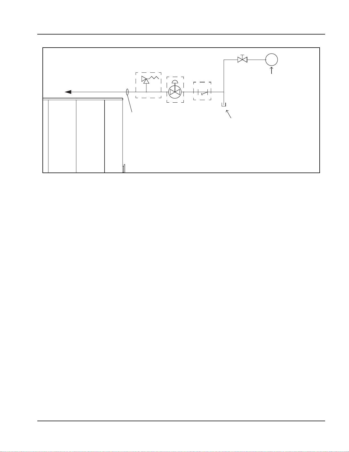
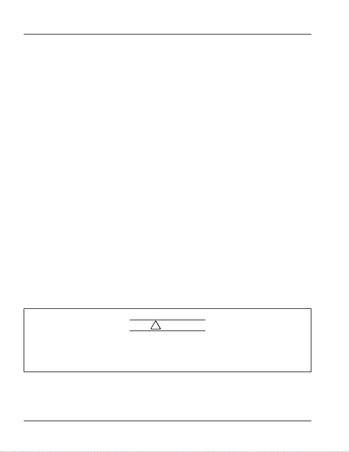
Figure 2-5 Gas Piping
Section 2 — Installation
TO GAS TRAIN
As required
Same or large r tha n boiler ga s connect ion
size
As required
As required
Ga s header - size for boiler room
capacity and to minimize press ure loss
Dr ip le g r e quir e d f or a ny ver t ic a l ru n of
pipi ng
2.7.5 Gas Supply Pipe Sizing
For proper operation of a single unit or a multiple unit installation, CB recommends that the gas piping be
sized to allow no more than 0.3" w.c. pressure drop from the source (gas header or utility meter) to the final
unit location. Higher supply pressure systems may allow for a greater pressure drop. In ALL cases, minimum
supply pressures must be met for proper operation of the boiler(s). The gas supplier (utility) should be
consulted to confirm that sufficient volume and normal pressure are provided to the building at the
discharge side of the gas meter or supply pipe.
For installations of new boilers into an existing building, gas pressure should be measured with a
manometer to ensure sufficient pressure is available. A survey of all connected gas-using devices should be
made. If appliances other than the boiler or boilers are connected to the gas supply line, then a
determination must be made of how much flow volume (cfh) will be demanded at one time and the pressure
drop requirement when all appliances are firing.
The total length of gas piping and all fittings must be considered when sizing the gas piping. Total equivalent
length should be calculated from the utility meter or source to the final unit connection. As a minimum
guideline, see gas piping Tables 2-6 and 2-7. The data in these tables is from the NFPA 54 source book,
2006 edition.
To verify the input of each device that is connected to the gas piping, obtain the btu/hr input and divide this
input by the calorific value of the gas that will be utilized. For instance, a unit with 4,000,000 btu/hr input
divided by a gas calorific value of 1060 will result in a flow of 3774 cfh. The single boiler is approximately
20 feet from the gas supply header source. And with a measured gas supply pressure of 10" w.c. we find
from Table 2-6 that a supply pipe size of 3" should be used as a minimum.
Part No. 750-363 2-11
Page 26
Section 2 — Installation
Table 2-6: Gas Line Capacity - Schedule 40 Metallic Pipe
Pipe Size
Nominal 2-1/2" 3" 4"
Actual I.D. 2.469" 3.068" 4.026"
Length in feet **Maximum Capacity in Cubic Feet of Gas per Hour (cfh)
10 4,860 8,580 17,500
20 5,900 12,000
30 9,660
40 8,290
50 7,330
60 6,640
70 6,110
80 5,680
90 5,330
100 5,040
125 4,460
150 4,050
175
200
**Fuel: Natural Gas
**Inlet Pressure: Less than 2.0 psi
**Pressure Drop: 0.30" w.c.
**Specific Gravity: 0.60
Table 2-7: Gas Line Capacity - Schedule 40 Metallic Pipe
Pipe Size
Nominal 2" 2-1/2" 3" 4"
Actual I.D. 2.067" 2.469" 3.068" 4.026"
Length in feet **Maximum Capacity in Cubic Feet of Gas per Hour (cfh)
10 4,020 6,400 11,300 23,100
20 4,400 7,780 15,900
30 6,250 12,700
40 5,350 10,900
50 4,740 9,600
60 4,290 8,760
70 8,050
80 7,490
90 7,030
100 6,640
125 5,890
150 5,330
175 4,910
200 4,560
**Fuel: Natural Gas
**Inlet Pressure: Less than 2.0 psi
**Pressure Drop: 0.50" w.c.
**Specific Gravity: 0.60
2-12 Part No. 750-363
Page 27
Section 2 — Installation
4
2.7.6 Gas Header
Design of a single common gas header with individual takeoffs for a multiple unit installation is
recommended. Boiler gas manifold piping should be sized based on the volume requirements and lengths
between boilers and the fuel main header.
For installations with a mixed sized use, determine the flow of each unit and total the input. With the total
input, determine length of run from the source and determine what size header will be needed for the flow
of all units firing.
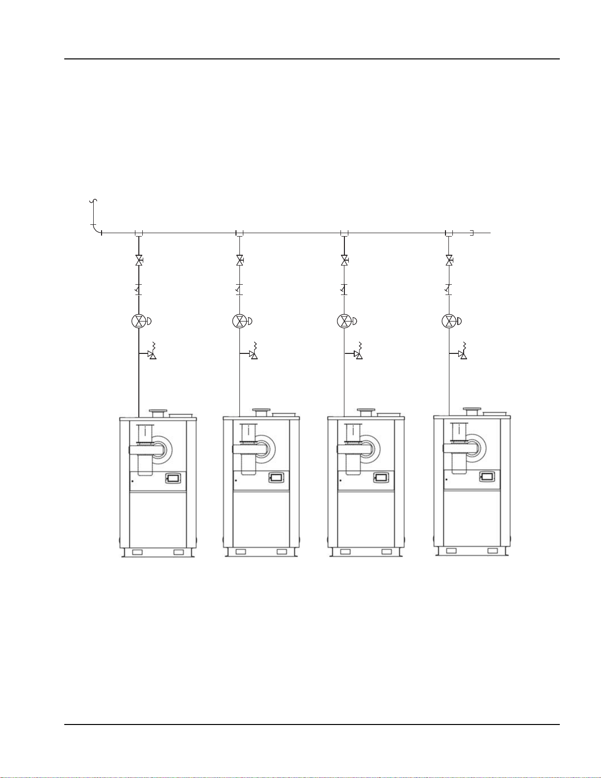
Figure 2-6 Gas header piping
From
Meter
Manua l Shut Off
Gas Strainer
Re g ula to r
See Note 1
Gas Hea der Piping, Typical
Header Pipe
Re lie f Valve
See Note 5
NOTES:
1. Dedicated gas pressure regula tor required for each boiler if gas supply greater than max. pressure in Table 1
2. Refer to local fuel gas codes when applicable.
3. Header to be sized for room capacit y.
4. Provision required for measuring gas supply pressure at boiler.
5. Ove rpre ss ur e prote ct ion re quired if gas supply press ure > 5 ps ig.
Part No. 750-363 2-13
Page 28
Section 2 — Installation
2.8 BOILER WATER PIPING
2.8.1 General
All boiler hot water outlet and return piping is connected at the rear of the boiler. Piping is to be installed
per local codes and regulations.The pipelines for the hot water outlet and return may be connected in the
usual manner without removing the cladding elements. Unused connectors must be safely blanked off.
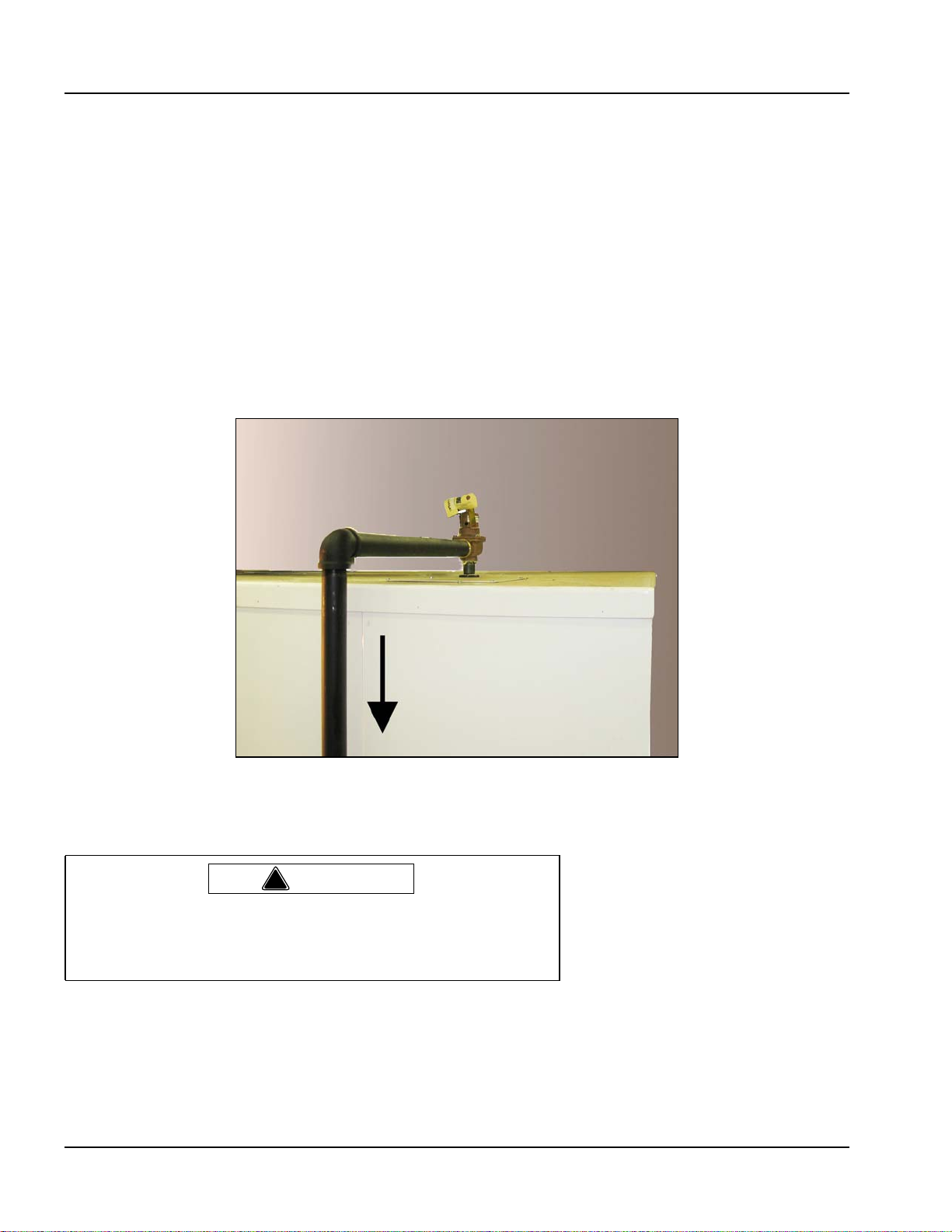
2.8.2 Safety valve
The pressure relief valve (safety valve) should be piped from the coupling on top of the boiler (see Figure
2-7). Use pipe sealing compound and a flat sided wrench when securing the Safety relief valve. Do not use
a pipe wrench and do not over tighten the relief valve. The safety valve must be mounted in a vertical
position so that discharge piping and code-required drains can be properly piped to prevent buildup of back
pressure and accumulation of foreign material around the valve seat area. Apply only a moderate amount
of pipe compound to male threads and avoid overtightening, which can distort the seats. Use only flatjawed wrenches on the flats provided.
Figure 2-7 Safety relief valve piped to safe point of discharge
Warning
!
Only properly certified personnel such as the safety valve
manufacturer’s certified representative should adjust or repair the
boiler safety valve. Failure to follow this warning could result in
serious personal injury or death.
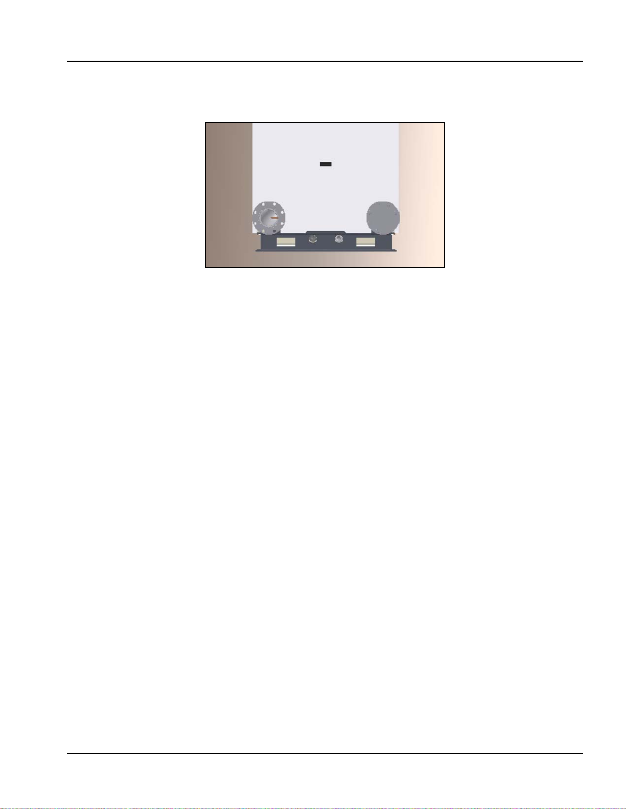
2.8.3 Dual return design
The Model CFLC features separate high and low temperature return water connections, allowing for
condensing performance within high temperature hydronic systems. With as little as 10% return water at
or below 120 deg F, the Model CFLC will achieve condensing performance, with associated gains in
efficiency.
2-14 Part No. 750-363
Page 29
Section 2 — Installation
If using only a single (common) return, the low temperature connection should be used. The low
temperature connection is on the left when facing the rear of the boiler.
Low Temp.
Return
High Temp.
Return
Figure 2-8 Dual returns
2.8.4 Pressure drop curves
The information in Figure 2-9 and in Tables 2-8 and 2-9 can help in determining pump requirements for
Model CFLC installations.
Part No. 750-363 2-15
Page 30
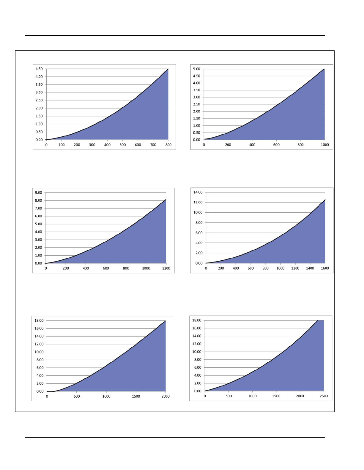
Section 2 — Installation
CFLC 4000 CFLC 5000
Pressure PSI
Pressure PSI
Flow rate GPM
CFLC 6000
Flow rate GPM
Pressure PSI
Flow rate GPM
CFLC 8000
Pressure PSI
Flow rate GPM
Pressure PSI
CFLC 10000
Pressure PSI
Flow rate GPM
CFLC 12000
Flow rate GPM
Figure 2-9 Pressure Drop Curves, CFLC
2-16 Part No. 750-363
Page 31

Section 2 — Installation
Table 2-8: CFLC flow rates @ rated capacity
System Temperature Drop Deg F
10 20 40 60 80 100
Boiler Size
4000 752 376 188 125 94 75
5000 940 470 235 157 117 94
6000 1128 564 282 188 141 113
8000 1504 752 376 251 188 150
10000 1880 940 470 313 235 188
12000 2255 1128 564 376 282 226
Flow rates relative to temperature drop so as not to exceed boiler output.
Based on 94% nominal efficiency.
Flow Rate GPM
Table 2-9: CFLC flow rates (metric)
System Temperature Drop Deg C
6 1122334456
Boiler Size
4000 171 85 43 28 21 17
5000 213 107 53 36 27 21
6000 256 128 64 43 32 26
8000 341 171 85 57 43 34
10000 427 213 107 71 53 43
12000 512 256 128 85 64 51
Flow rates relative to temperature drop so as not to exceed boiler output.
Based on 94% nominal efficiency.
Flow Rate m3/hr
Part No. 750-363 2-17
Page 32

Section 2 — Installation
2.9 MINIMUM BOILER OVERPRESSURE
To prevent the occurrence of flash steam within the boiler or system, hot water boilers must operate with
proper over-pressure. System over-pressure requirements are shown in Table 2-8.
Note: The ASME Code Section IV limits the maximum setting of the excess temperature control to 250 F (121 C). This is to ensure
that water temperature will not reach the boiling point (steaming) and therefore, so as not to exceed the maximum limit of this
control and in compliance with the Code, the operating limit of 230 F (110 C) is set for normal boiler operation.
While proper overpressure is required, a means to relieve excess pressure at or beyond the design pressure of
the boiler must be provided. As boiler water is heated, expansion occurs. And this expansion must be
accounted for either with an expansion tank (air filled) or with a bladder type tank. These devices permit the
water pressure to expand outside of the boiler and not impact the pressure vessel or pressure relieving
device. In accordance with code, each boiler is equipped with an ASME approved safety relieving device
should pressure build-up occur.
Table 2-10: Model CFLC Minimum Over Pressure Requirements (100% water)
Outlet Water Temperature Minimum System Pressure
(°F) (°C) PSIG Bar
130-180 54-82 12 0.83
181-185 83-85 15 1.03
186-205 86-96 18 1.24
206-215 97-101 24 1.66
216-225 102-107 30 2.07
226-240 108-116 42 2.90
2.10 CONDENSATE REMOVAL AND TREATMENT
The condensate generated during normal boiler operation must be removed in accordance with local codes
and regulations. The condensate can be piped to a local treatment system or run into the optional
condensate treatment assembly.
The water trap must be filled with water prior to commissioning and checked or refilled at each required
maintenance interval.
Notice
The condensate occurring during operation in both the boiler and the flue gas pipeline should be neutralized and piped
to a safe drain. The conditions for the discharge of condensates into public drain systems are determined by the local
authorities and municipalities.
Condensate leaving the boiler normally has a pH of 4-6. The responsible authority will inform you if a higher
pH value is required for condensate piped to drain. The CFLC neutralization system contains a compound
which acts to increase the pH of the condensate flowing through it. The neutralization system comprises
the plastic neutralization tank with condensate inlet, granulate chamber and condensate outlet. The system
is installed per Figure 2-11.
2-18 Part No. 750-363
Page 33

DRAIN
Section 2 — Installation
BOILER REAR
WARM WATER RETURN
CONDENSATE DRAIN
COLD WATER RETURN
A CONDENSATE TRAP
IS PIPED WITHIN THE
BOILER.
Figure 2-10 Condensate Piped Direct to Drain
Note: To ensure compliance with regulations, it is important to contact the responsible authorities prior
to the planning and execution of the boiler installation. Condensate flow of 20 to 80 GPH can be
expected depending on boiler size and return water temperature.
2.10.1 Condensate tank setup options
(1) Condensate direct to drain - The condensate is piped directly to a drain through the piping and water
trap supplied during installation (see Figure 2-10).
(2) Condensate to treatment tank - The condensate is held in a condensate tank(s) under or near the boiler.
The condensate is neutralized as it passes through a bed of granular material. The neutralized condensate
is then piped to the drain.
• To install the system, assemble the tank and fittings per instructions supplied with tank. Neutralization media are
already installed in tank.
• For CFLC 4000/5000 the tank must be installed external to the boiler (Figure 2-11). For sizes 6000-12000 the
tank(s) may be mounted internally or externally.
• Install the condensate tank cover and connect tank to boiler condensate discharge.
Pipe to an appropriate drain.
Piping is to be a minimum of 1-1/4” NPT.
Part No. 750-363 2-19
Page 34

Section 2 — Installation
Figure 2-11 Condensate Treatment Tank - external
SIZE 6000-8000
SIZES 10,000-12,000
Figure 2-12 Condensate Treatment Tank - internal
The neutralization media will require periodic
replacement, to be determined by pH analysis of
condensate. If condensate is too acidic (pH is below
acceptable value) the neutralization media should
be replaced.
The number of condensate treatment tanks required
depends on the total amount of condensate
produced by the system. As a general rule, CB
recommends one tank per boiler for sizes 4,000 -
Table 2-8 CFLC Max Condensation
CFLC Model BTU/hr
4000 4,000,000 27
5000 5,000,000 34
6000 6,000,000 41
8000 8,000,000 54
10000 10,000,000 68
12000 12,000,000 82
Condensation
Max.
GPH
8,000 and two tanks for sizes 10,000 - 12,000.
2-20 Part No. 750-363
Page 35

Section 2 — Installation
2.11 ELECTRICAL CONNECTIONS
A qualified electrician or service technician must make the electrical connections to the boiler.
For specific information on your boiler electrical system refer to the Cleaver-Brooks wiring diagram provided
with the boiler.
Power is to be run from the top left corner of the boiler to the control panel (see Figure 2-13). AC power is
to be connected to the incoming power terminals.
Note: The following temperature sensor cables should not be run near the three phase incoming power
wiring.
• Hot water outlet temperature sensor.
• Hot water return temperature sensor.
• Stack temperature sensor (optional).
• Outdoor temperature sensor (optional).
• Header water temperature sensor (optional).
Warning
!
Ensure ignition cables are properly connected and not in direct contact with any sharp metal edges.
Part No. 750-363 2-21
Page 36

Section 2 — Installation
FALCON
Figure 2-13 Electrical Connections CFLC
2-22 Part No. 750-363
Page 37

2.12 WIRING DIAGRAM
208V, 230V, 575V 3 PHASE ALSO SUPPORTED
Section 2 — Installation
Figure 2-14 CFLC 6000 - 12000 Wiring Diagram, single fuel (typical)
Note: Wiring diagrams shown are examples only.
Installations may vary. For specific installations
consult the wiring diagram provided with the boiler.
Part No. 750-363 2-23
Page 38

Section 2 — Installation
2-24 Part No. 750-363
Page 39

Section 3
Stack and Intake Vent Sizing and Installation
Venting Connections - General . . . . . . . . . . . . . . . . . . . . . . . . . . . . . . . . . . .3-2
Vertical Venting / Inside Combustion Air . . . . . . . . . . . . . . . . . . . . . . . . . . . . . 3-6
Vertical Venting / Direct Vent or Sealed Combustion Air . . . . . . . . . . . . . . . . . . 3-7
Venting for multiple units . . . . . . . . . . . . . . . . . . . . . . . . . . . . . . . . . . . . . . .3-8
Combustion Air / Boiler Room Ventilation Requirements . . . . . . . . . . . . . . . . . . 3-10
www.cleaverbrooks.com
Page 40

Section 3 — Stack and Intake Vent Sizing and Installation
3.1 VENTING CONNECTIONS - GENERAL
3.1.1 Appliance Categories
Proper installation of flue gas exhaust venting is critical for efficient,
reliable, and safe operation of the CFLC boiler. The boiler’s
appliance category is a major factor determining venting system
design.
Definitions:
Boilers are divided into four categories based on the pressure and
temperature produced in the exhaust stack and the likelihood of
condensate production in the vent.
• Category I. A boiler which operates with a non-positive vent static
pressure and with a vent gas temperature that avoids excessive
condensate production in the vent.
• Category II. A boiler which operates with a non-positive vent static
pressure and with a vent gas temperature that may cause
excessive condensate production in the vent.
• Category III. A boiler which operates with a positive vent pressure
and with a vent gas temperature that avoids excessive condensate
production in the vent.
Notice
For additional information on boiler
categorization, see appropriate
ANSI Z21 Standard and the latest
edition Standard of National Fuel
Gas Code or in Canada, the latest
edition of CSA Standard B149
Installation Code for Gas Burning
Appliances and Equipment, or
applicable provisions of local
building codes.
• Category IV. A boiler which operates with a positive vent pressure
and with a vent gas temperature that may cause excessive
condensate production in the vent.
Depending on the application, the Model CFLC may be considered
Category II, III, or IV. The specifying engineer should dictate flue
venting as appropriate to the installation. CFLC condensing
applications will typically utilize Category IV venting.
Warning
!
Contact the manufacturer of the vent material if there is any
question about the boiler categorization and suitability of a vent
material for application on a Category II, III or IV vent system.
Using improper venting materials can result in personal injury,
death or property damage.
3.1.2 Flue Venting System Design
The flue venting should be supported to maintain proper clearances
from combustible materials.
Flue venting should be supported by the building structure. The
maximum load that the boiler flue connection can support is 500
lbs.
Use insulated vent pipe spacers where the vent passes through
combustible roofs and walls.
3-2 Part No. 750-363
Page 41

Section 3 — Stack and Intake Vent Sizing and Installation
Vent material should be appropriate for the Appliance Category.
Application-specific information will further determine the material
selected.
For Category II, III & IV appliance categories, Cleaver-Brooks highly
recommends that the flue system be Listed to standard UL 1738
Special Gas Vent and be installed in accordance with the National
Fuel Gas Code (NFPA 54) or ANSI Z21.47/ CSA 2.3. Type B Vent
shall not be allowed for positive pressure (forced draft burner) or
condensing vent systems.
Draft calculations should be performed for any condensing boiler
flue system. It is good practice to perform calculations at several
operating conditions to ensure draft tolerances are maintained.
For best performance, individual, through-the-roof vertical flue
venting is recommended for CFLC boilers. Cleaver-Brooks
recommends vertical straight flue (no loss) or velocity cone flue
termination.
Note:Traditional rain caps should not be used, as moist,
condensing flue gases can be directed downward
toward the building and air intakes. In cold climates and
freezing ambient temperatures, rain caps can lead to ice
formation, air intake blockage, and flue blockage that
result from condensing water vapor in the flue gases.
Cleaver-Brooks discourages the use of horizontal through-the-wall
flue termination with CFLC boilers. Vertical flue terminations are
recommended for optimum combustion performance and building
exterior maintenance.
An active draft inducer may be necessary for a horizontal flue
arrangement that exceeds the allowable draft tolerance.
Contact the Cleaver-Brooks authorized representative for
consideration of horizontal flue termination with CFLC boilers.
3.1.3 Draft Tolerances
For Individual flue vented boilers:
Maximum allowed pressure at vent connection is minus 0.25
inches to plus 0.10 to WC.
Recommended maximum design pressure at vent connection is
minus 0.10 to plus 0.10 inches WC.
For common flue vented boilers:
Maximum allowed pressure at vent connection is minus 0.25 inch
to 0.0 inch WC.
Recommended maximum design pressure at vent connection is
minus 0.10 to 0.0 inch WC.
3.1.4 Vent Terminal Location
Give special attention to the location of the vent termination to avoid
possibility of property damage, compromised performance, or
personal injury. For best results with condensing boilers, use vertical
straight (no loss) flue discharge or velocity cone termination. These
Figure 3-1 Vent Terminations
Part No. 750-363 3-3
Page 42

Section 3 — Stack and Intake Vent Sizing and Installation
terminations are suited to moving flue gases and water vapor away
from building exterior surfaces and air intakes.
1. Combustion gases can form a white vapor plume in the winter.
The plume could obstruct a window view if the termination is
installed in close proximity to windows.
2. Prevailing winds could cause freezing of condensate and water/
ice buildup on building, plants or roof.
3. The bottom of the vent terminal, as well as the air intake, shall
be located at least 24 inches above grade, including normal
snow line.
4. Un-insulated single-wall metal vent pipe shall not be used
outside in cold climates for venting combustion gas.
5. Through-the-wall vents for Category II and IV appliances and
non-categorized condensing appliances shall not terminate over
public walkways or over an area where condensate or vapor
could create a nuisance or hazard or could be detrimental to the
operation of other equipment. Where local experience indicates
that condensate is a problem with Category III appliances, this
provision shall also apply.
6. Locate and guard vent termination to prevent accidental contact
by people and pets.
7. DO NOT terminate vent in window well, alcove, stairwell or other
recessed area, unless previously approved by local authority.
8. DO NOT terminate above any door, window, or gravity air intake.
Condensate can freeze causing ice formations.
9. Locate or guard vent to prevent condensate from damaging
exterior finishes. Use a 2' x 2' rust resistant sheet metal backing
plate against brick or masonry surfaces. Extend the termination
at least 2” from exterior surface.
10. DO NOT extend exposed stack pipe outside of building. In
winter conditions condensate could freeze and block stack
pipe.
During winter months check the vent cap and make sure no
Note:
blockage occurs from build up of snow. Condensate can
freeze on the vent cap. Frozen condensate on the vent cap
can result in a blocked flue condition.
U.S. Installations- Refer to latest edition of the National Fuel Gas
Code.
Vent termination requirements are as follows:
1. Flue vent must terminate at least eight (8) feet above or eight (8)
feet horizontal from any HVAC air inlet to the building, including
combustion air intakes. Vent must terminate at least three (3)
feet above any door or window.
2. The vent must not be less than seven (7) feet above grade when
located adjacent to public walkways.
3. Terminate vent at least three (3) feet above any forced air inlet
located within ten (10) feet.
3-4 Part No. 750-363
Page 43

Section 3 — Stack and Intake Vent Sizing and Installation
4. Vent must terminate at least four (4) feet horizontally, and in no
case above or below unless four (4) feet horizontal distance is
maintained, from electric meters, gas meters, regulators, and
relief equipment.
5. Terminate vent at least six (6) feet away from adjacent walls.
6. DO NOT terminate vent closer than five (5) feet below roof
overhang.
Canada Installations- Refer to the latest edition of CAN/CSAB149.1 and B149.2
A vent shall not terminate:
1. Directly above a paved sidewalk or driveway which is located
between two single family dwellings and serves both dwellings.
2. Less than 7 ft. (2.13m) above a paved sidewalk or paved
driveway located on public property.
3. Within 6 ft. (1.8m) of a mechanical air supply inlet to any
building.
4. Above a meter/regulator assembly within 3 ft. (900mm)
horizontally of the vertical center-line of the regulator.
5. Within 6 ft. (1.8m) if any gas service regulator vent outlet.
6. Less than 1 ft. (300mm) above grade level.
7. Within 3 ft. (1m) of a window or door which can be opened in
any building, any non-mechanical air supply inlet to any building
to the combustion air inlet of any other appliance.
8. Underneath a veranda, porch or deck, unless:
• The veranda, porch or deck is fully open on a minimum
of two sides beneath the floor.
• The distance between the top of the vent termination
and the underside of the veranda, porch or deck is
greater than 1 ft. (30cm)
Note: For direct vent installations where the air is piped in
from outside, a protective screen on the air inlet
termination elbow must be used to act as an inlet
screen.
Warning
!
Examine the venting system at least once a year. Check all joints
and vent pipe connections for tightness, corrosion or deterioration.
Venting Installation Tips
Support piping:
• Horizontal runs- at least every five (5) feet.
• Vertical runs - use braces.
• Under or near elbows
Part No. 750-363 3-5
Page 44

Section 3 — Stack and Intake Vent Sizing and Installation
Follow items listed below to avoid personal injury or property
damage.
• Cut nonmetallic vent pipe with fine-toothed hacksaw (34 teeth per
inch).
• Do not use nonmetallic vent pipe or fittings that are cracked or
damaged.
• Do not use nonmetallic vent fittings if they are cut or altered.
• Do not drill holes, or use screws or rivets, in nonmetallic vent pipe
or fittings.
3.2 VERTICAL VENTING / INSIDE COMBUSTION AIR
Caution
!
10'-0" or Less
24"
Minimum
Flue Gas Vent
Termination
48"
Minimum
Figure 3-2 Vertical Stack with Inside Combustion Air
3-6 Part No. 750-363
Page 45

Section 3 — Stack and Intake Vent Sizing and Installation
These installations utilize the boiler-mounted blower to vent the
combustion products to the outside. Combustion air is taken from
inside the room and the vent is installed vertically through the roof
to the outside. Adequate combustion and ventilation air must be
supplied to the boiler room in accordance with the National Fuel
Gas Code or, in Canada, the latest edition of CAN/CSA-B 149.1 and
149.2 Installation Code for Gas Burning Appliances and
Equipment.
To prevent accumulation of condensation in the vent, it is required
to install the horizontal portion of vent with a slight slope of at least
1/4” per foot of horizontal run, pitched either back to the boiler or
to a low point equipped with suitable condensate trap and drain.
Warning
!
No substitutions of flue pipe or vent cap material are allowed. Such
substitutions would jeopardize the safety and health of inhabitants.
3.3 VERTICAL VENTING / DIRECT VENT OR
SEALED COMBUSTION AIR
Vent Termination
Minimum
48"
48" Minimum
12"
Minimum
above roof
or snow line
Air Intake (w/Screen)
24" Minimum
Vent Termination
36" Minimum
above intake
48" Minimum
Air Intake (w/Screen)
12" Minimum
above parapet
or snow line
With parapet wall
Figure 3-3 Vertical Stack with Direct Venting/Sealed Combustion
Part No. 750-363 3-7
Page 46

Section 3 — Stack and Intake Vent Sizing and Installation
These installations utilize the boiler-mounted blower to draw
combustion air from outside and vent combustion products to the
outside.
To prevent accumulation of condensation in the vent, it is required
to install the horizontal portion of vent with a slight slope of at least
1/4” per foot of horizontal run, pitched either back to the boiler or
to a low point equipped with suitable condensate trap and drain.
3.4 VENTING FOR MULTIPLE UNITS
Cleaver-Brooks recommends that each model CFLC in a multiple
boiler installation be vented individually for safe, reliable, and
optimum combustion performance. If common flue venting is the
only feasible solution, ensure an unrestricted flow of flue gas from
each boiler and a draft within the allowable tolerances.
To help maintain balanced draft conditions in common flue vented
CFLC boiler systems, isolation dampers (flue or combustion air)
with “prove open” switches are required. The damper prove must be
wired in the boiler's safety interlock circuit.
When there is insufficient (or excessive) vertical flue stack to ensure
neutral draft, active draft controls are recommended for common
flue vented CFLC boilers.
Ductwork sizing, layout, and connections require special attention
in common flue venting systems. Good design practice should be
followed such as the use of 45 degree wye connections (not 'tees')
for boiler branch connections into common flue duct. The number
of elbows should be kept to a minimum.
Common flue venting should always be larger than the boiler branch
connection joining it. As a rule-of-thumb, the cross-sectional area of
any ductwork downstream of a wye branch connection should be
equal to or greater than the combined area of the incoming vent
sections.
See Examples 1-3 below for suggested venting arrangements.
When multiple CFLC boiler are connected in a Falcon Lead-Lag
network, a 'Fan rate during off cycle' feature is available. When
enabled, a boiler that goes off line and completes its post purge will
continue to operate the combustion air blower at a user-selectable
rate. This feature provides a further measure when needed to
prevent flue gases from flowing back into the boiler and room.
To ensure safe and reliable operation of multiple CFLC boilers in a
common flue venting system, please contact the Cleaver-Brooks
authorized representative. Cleaver-Brooks offers proven flue
systems for all Cleaver-Brooks models through its Exhaust Solutions
group.
3-8 Part No. 750-363
Page 47

EXAMPLE 1
Section 3 — Stack and Intake Vent Sizing and Installation
GOOD
3
BAD
26”
o
45
14” 14”
From boilers
From boilers
26”
26”
to roof
vent
14”
EXAMPLE 2
GOOD
3
14”
20”
From boilers
45
o
14”
BAD
From boilers
Part No. 750-363 3-9
Page 48

Section 3 — Stack and Intake Vent Sizing and Installation
EXAMPLE 3
GOOD
3
GOOD
26”
o
45
14” 14”
From boilers
16”
16” 16”
From Boilers
26”
24”
26”
30”
14”
16”
to roof
vent
BAD
14”
14” 14”
From Boilers
14”
14”
14”
Combustion air methods
ROOM AIR
Air is drawn from the boiler room.
DIRECT VENTING
Air is ducted from the outdoors to
the burner cabinet. No direct
connection to burner air intake.
SEALED COMBUSTION
Outside air is ducted directly to
the burner air intake.
3.5 COMBUSTI0N AIR/BOILER ROOM
VENTILATION REQUIREMENTS
The boiler(s) must be supplied with adequate quantities of
uncontaminated air to support proper combustion and equipment
ventilation. Air shall be free of chlorides, halogens, fluorocarbons,
construction dust or other contaminants that are detrimental to the
burner/boiler. If these contaminants are present, we recommend the
use of direct vent combustion provided the outside air source is
uncontaminated.
Combustion air can be supplied by means of conventional boiler
room venting, where ambient combustion air is drawn from the area
immediately surrounding the boiler (boiler room must be positive
pressure*), or with air ducted from the outdoors to the burner
cabinet (direct venting) or burner air intake (sealed combustion). All
installations must comply with local Codes and with NFPA 54 (the
National Fuel Gas Code - NFGC) for the U.S. and for Canada, CAN/
CGA B 149.1 and B 149.2.
*A boiler room exhaust fan is not recommended as this type of device can cause
a negative pressure in the boiler room if using a conventional wall louvered air
intake.
3-10 Part No. 750-363
Page 49

Section 3 — Stack and Intake Vent Sizing and Installation
“Sealed combustion” is a special air ducting method that implies a
gas-tight ducted connection to the burner’s air intake. Contact your
Cleaver-Brooks authorized representative to determine if direct vent
or sealed combustion is appropriate for the installation.
C-B provides optional Combustion Air Adapter kits which can be
used in either Direct Vent or Sealed Combustion configurations.
In accordance with NFPA54, the required volume of indoor air shall
be determined in accordance with the “Standard Method” or
“Known Air Infiltration Rate” Method. Where the air infiltration rate
is known to be less than 0.40 Air Changes per Hour, the Known Air
Infiltration Rate Method shall be used (see Section 8.3 in the
NFPA54 Handbook for additional information).
3.5.1 Air Supply - Unconfined Spaces (For U.S. Installations
Only)
A. All Air From Inside the Building - If all combustion air is
drawn from inside the building (the mechanical equipment
room does not receive air from outside via louvers or vent
openings and the boiler is not equipped with direct vent
combustion) and the boiler is located in an unconfined
space, use the following guidelines:
1. The mechanical equipment room must be provided with
two permanent openings linked directly with additional
room (s) of sufficient volume so that the combined
volume of all spaces meet the criteria for an unconfined
space. Note: An "unconfined space" is defined as a space
whose volume is more than 50 cubic feet per 1,000 Btu
per hour of aggregate input rating of all appliances
installed in that space.
2. Each opening must have a minimum free area of one
square inch per 1,000 Btu per hour of the total input
rating of all gas utilizing equipment in the mechanical
room.
3. One opening must terminate within twelve inches of the
top, and one opening must terminate within twelve
inches of the bottom of the room.
4. Refer to the NFGC, Section 8.3 for additional
information.
B. All Air From Outdoors - If all combustion air will be received from outside the building (the
mechanical room equipment is linked with the outdoors), the following methods can be used:
1. Two Opening Method - The mechanical equipment room
must be provided with two permanent openings, one
terminating within twelve inches from the top, and one
opening terminating within twelve inches of the bottom of
the room.
Part No. 750-363 3-11
Page 50

Section 3 — Stack and Intake Vent Sizing and Installation
2. The openings must be linked directly (Figure 3-4) or by
3. Each opening must have a minimum free area of one
4. The minimum free area required for horizontal ducts is
ducts (Figure 3-5) with the outdoors.
square inch per 4,000 Btu per hour of total input rating
of all equipment in the room, when the opening is directly
linked to the outdoors or through vertical ducts.
one square inch per 2,000 Btu per hour of total input
rating of all the equipment in the room.
GAS
VENT
CLEARFIRE
BOILER
GAS
VENT
WATER
HEATER
Figure 3-4 Two Opening Outside Wall Method
12" MINIMUM
FRESH AIR OPENING
INTERIOR WALL
FRESH AIR OPENING
12" MINIMUM
3-12 Part No. 750-363
Page 51

Section 3 — Stack and Intake Vent Sizing and Installation
CLEARFIRE
BOILER
GAS
VENT
GAS
VENT
WATER
HEATER
INTERIOR WALL
EXTERIOR WALL
Figure 3-5. Two Opening Ducted Method
12" MINIMUM
OUTLET AIR DUCT
FRESH AIR
INLET DUCT
12" MINIMUM
C. One Opening Method (Figure 3-6) - One permanent opening,
commencing within 12 inches of the top of the enclosure,
shall be provided.
1. The equipment shall have clearances of at least 1 inch
from the sides and back and 6 inches from the front of
the appliance.
2. The opening shall directly communicate with the
outdoors and shall have a minimum free area of 1 square
inch per 3000 BTU's per hour of the total input rating of
all equipment located in the enclosure, and not less than
the sum of the areas of all vent connectors in the confined
space.
3. Refer to the NFGC, Section 8.3 for additional
information.
Part No. 750-363 3-13
Page 52

Section 3 — Stack and Intake Vent Sizing and Installation
GAS
VENT
GAS
VENT
12" MINIMUM
FRESH AIR OPENING
EXTERIOR WALL
WATER
HEATER
Figure 3-6. One Opening Method
3.5.2 Air Supply - Engineered Method
When determining boiler room air requirements for an unconfined
space, the size of the room, airflow, and velocity of air must be
reviewed as follows:
1. Size (area) and location of air supply openings in the boiler
room.
A. Two permanent air supply openings in the outer walls of the
boiler room are recommended. Locate one at each end of the
boiler room, preferably below a height of 7 feet. This allows
air to sweep the length of the boiler. See Figure 3-7.
B. Air supply openings can be louvered for weather protection,
but they should not be covered with fine mesh wire, as this
type of covering has poor air flow qualities and is subject to
clogging with dirt and dust.
C. A vent fan in the boiler room is not recommended, as it could
create a slight vacuum under certain conditions and cause
variations in the quantity of combustion air. This can result
in unsafe burner performance.
3-14 Part No. 750-363
Page 53

Section 3 — Stack and Intake Vent Sizing and Installation
D. Under no condition should the total area of the air supply
openings be less than one square foot.
FRESH AIR OPENING
EXTERIOR WALL
GAS
VENT
GAS
VENT
WATER
HEATER
FRESH AIR OPENING
EXTERIOR WALL
Figure 3-7. Two Opening Engineered Method
E. Size the openings by using the formula:
Area in square feet = cfm/fpm
Where cfm = cubic feet per minute of air
Where fpm = feet per minute of air
2. Amount of Air Required (cfm).
A. Combustion Air = 0.25 cfm per kBtuh.
B. Ventilation Air = 0.05 cfm per kBtuh.
C. Total air = 0.3 cfm per kBtuh (up to 1000 feet elevation.
Add 3% more per 1000 feet of added elevation).
3. Acceptable air velocity in the Boiler Room (fpm).
A. From floor to 7 feet high = 250 fpm.
B. Above 7 feet above floor = 500 fpm.
Example: Determine the area of the boiler room air supply openings
for (2) CFLC 4000 boilers at 750 feet elevation. The air openings to
be 5 feet above floor level.
• Air required: 4000 x 2 = 8000 kBtuh. From 2C above,
8000 x 0.3 = 2400 cfm.
Table 3-1 Boiler room air
CFLC
20 ppm
4000 1000 200 1200
5000 1250 250 1500
6000 1500 300 1800
8000 2000 400 2400
10000 2500 500 3000
12000 3000 600 3600
CFLC
9 ppm
4000 1075 200 1275
5000 1350 250 1600
6000 1625 300 1925
8000 2150 400 2550
10000 2700 500 3200
12000 3225 600 3825
Combustion
air SCFM
Combustion
air SCFM
Vent air
SCFM
Vent air
SCFM
Total
room air
SCFM
Total
room air
SCFM
Part No. 750-363 3-15
Page 54

Section 3 — Stack and Intake Vent Sizing and Installation
• Air Velocity: Up to 7 feet = 250 fpm from 3 above.
• Area required: Area = cfm/fpm = 2400/250 = 9.6 square
feet total.
• Area/Opening: 9.6/2 = 4.8 sq-ft/opening (2 required).
Consult local codes, which may supersede these requirements.
Direct Venting/Sealed Combustion
If combustion air will be drawn directly from the outside by means of
a duct connected to the burner cabinet (Direct Venting) or air intake
(Sealed Combustion), use the following as a guide:
1. Install combustion air vent in accordance with the boiler's
Operating and Maintenance manual.
2. Provide for adequate ventilation of the boiler room or
mechanical equipment room.
3. In extremely cold climates, to mitigate the potential for freezing
and to reduce standby losses, a motorized isolation damper is
necessary to prevent the circulation of cold air through the boiler
during non-operating hours.
4. Refer to Figure 3-3 for suggested piping of direct vent/sealed
combustion installations. Figure 3-8 shows the optional kit
providing easy adaptation of the contractor supplied air duct to
boiler connection. Table 3-2 shows vent sizing information.
Notice
Caution
!
Combustion air ductwork should
be securely attached to the boiler
casing. No weight should be supported by the venturi. Venting
should be installed to allow easy
disconnection for burner service.
For best results, the CleaverBrooks direct vent/sealed combustion kit is recommended. See T able
6-2 for kit part numbers.
For Direct Vent use, omit the flexible
duct connector and air intake collar.
For Sealed Combustion, assemble all
components as shown.
Figure 3-8. Optional Direct Vent/Sealed Combustion Kit
3-16 Part No. 750-363
Page 55

Section 3 — Stack and Intake Vent Sizing and Installation
Table 3-2. CFLC Combustion Air and Flue Venting Requirements for Individual Boiler Venting
20ppm NOx Combustion air
SCFM
CFLC 4000 1000 10 0.25 10” or 12” 14” -0.25/+0.10”
CFLC 5000 1250 12 0.25 12” 14” -0.25/+0.10”
CFLC 6000 1500 14 0.25 14” or 16” 16” -0.25/+0.10”
CFLC 8000 2000 14 0.25 14” or 16” 16” -0.25/+0.10”
CFLC 10000 2500 16 0.50 16” or 18” 20” -0.25/+0.10”
CFLC 12000 3000 18 0.50 18” 20” -0.25/+0.10”
9ppm NOx
CFLC 4000 1075 10 0.25 10” or 12” 14” -0.25/+0.10”
CFLC 5000 1350 12 0.25 12” 14” -0.25/+0.10”
CFLC 6000 1625 14 0.25 14” or 16” 16” -0.25/+0.10”
CFLC 8000 2150 16 0.25 14” or 16” 16” -0.25/+0.10”
CFLC 10000 2700 16 0.50 16” or 18” 20” -0.25/+0.10”
CFLC 12000 3225 18 0.50 18” 20” -0.25/+0.10”
Minimum duct
diameter inches
Max allowable
comb. air pressure
drop (inches WC)
Direct vent
adapter kit
options
Flue diameter Draft tolerance
(inches WC)
Part No. 750-363 3-17
Page 56

Section 3 — Stack and Intake Vent Sizing and Installation
3-18 Part No. 750-363
Page 57

Section 4
Commissioning
Operating Conditions . . . . . . . . . . . . . . . . . . . . . . . . . . . . . . . . . . . . 4-2
Filling Boiler . . . . . . . . . . . . . . . . . . . . . . . . . . . . . . . . . . . . . . . . . . 4-2
Control Setpoints . . . . . . . . . . . . . . . . . . . . . . . . . . . . . . . . . . . . . . . 4-2
Model CFLC Boiler / Burner Controller . . . . . . . . . . . . . . . . . . . . . . . . 4-3
Falcon Display/Operator Interface . . . . . . . . . . . . . . . . . . . . . . . . . . . 4-4
Controller Configuration . . . . . . . . . . . . . . . . . . . . . . . . . . . . . . . . . . 4-7
Variable Speed Drive Settings . . . . . . . . . . . . . . . . . . . . . . . . . . . . . . 4-9
Burner Sequence . . . . . . . . . . . . . . . . . . . . . . . . . . . . . . . . . . . . . . 4-10
Fan Speed Settings . . . . . . . . . . . . . . . . . . . . . . . . . . . . . . . . . . . . 4-10
Initial start-up procedure . . . . . . . . . . . . . . . . . . . . . . . . . . . . . . . . 4-10
Post start-up checkout procedure . . . . . . . . . . . . . . . . . . . . . . . . . . 4-17
Falcon Control Functions and Customer Interface . . . . . . . . . . . . . . . 4-18
Warning
!
The boiler and its gas connection must be
leak tested before placing the boiler in
operation.
www.cleaverbrooks.com
Page 58

Section 4 — Commissioning
4.1 OPERATING CONDITIONS
• The installation site should be as free as possible from vibration, dust, and corrosive media
• The controllers should be located as far as possible from sources of
electromagnetic fields, such as frequency converters or high-voltage
ignition transformers
• Control panel must be connected to earth ground.
• Refer to Section 3 in this manual for combustion air requirements.
When using direct vent
combustion in cold climates,
special care must be taken to
Warning
!
observe combustion air
temperature limits. Failure to
Boiler room ambient conditions
Relative humidity
Ambient temperature range 0
Storage temperature range -40
Combustion air temperature 0
< 85% non-condensing
o
o
C to 50 oC / 32oF to 122oF
o
C to 60 oC / -40oF to 140oF
C to 50 oC / 32oF to 122oF
follow this precaution may lead
to equipment damage or unsafe
operation.
4.2 FILLING BOILER
The system should be flushed, preferably with the boiler isolated, before operating the boiler.
When filling the boiler and/or hydronic system, water should be circulated to allow entrapped air to escape
at appropriate air venting provisions. Check to ensure that no leaks appear at any pipe connections and
correct if water leaks are noticed. When no air remains in the boiler, it will be possible to reset the low water
cutoff. If the low water cutoff can not be reset, it is likely that some air remains in the boiler.
4.3 CONTROL SETPOINTS
Preliminary settings of the burner/boiler safety controls are necessary for the initial starting of the boiler.
After the burner has been properly set, minor adjustments to these controls may be necessary for the
particular installation. For initial starting, set the following controls accordingly:
1. Combustion Air Proving Switch - Set the dial @ minimum.
2. Low Gas Pressure Switch - Set the dial @ minimum.
3. High Gas Pressure Switch - Set the dial @ maximum.
4. High Air Pressure Switch - Set the dial @ maximum (for operational settings see Table 4-2).
Depress all manual reset buttons for all controls prior to starting.
Note:Ensure that the post-startup checkout procedure (section 4.11) is observed following
commissioning.
4-2 Part No. 750-363
Page 59

4.4 MODEL CFLC BOILER / BURNER
CONTROLLER
The Model CFLC boiler uses the Falcon hydronic boiler
control system. Primary controller functions include:
• Flame supervision
• Burner sequencing
• Heating/modulation control
• Hot water system pump control
• High Limit temperature control
• Thermowell-mounted NTC temperature sensors to provide
measured process variable signals to the controller.
Additional features include:
• User-friendly touchscreen interface
• Modbus communication capability
• Alarm/lockout messaging with history (last 15 messages)
• Annunciation
• Outdoor reset
• Central Heating and Domestic Hot Water loop control
• Password protection of configurable parameters
• Time of Day (dual setpoint) control
Section 4 — Commissioning
Figure 4-1 Opening control panel
Figure 4-2 Controller status LEDs and reset button
• High Stack Temperature limit
• Remote reset
• Lead/Lag sequencing and modulation
• (3) configurable pump relays
• Remote modulation/remote setpoint
• Frost protection
• Warm weather shutdown
Part No. 750-363 4-3
Page 60

Section 4 — Commissioning
Please review the tables within this Commissioning section to familiarize yourself with the functions and
parameters of the Controller. Also see Appendices A and B for details on control configuration and operation.
Warning
!
The Model CFLC is factory tested. Nevertheless, all burner safety
controls should be checked upon installation, prior to initial firing.
Failure to verify burner control functioning could result in severe
bodily injury or death.
Figure 4-3 Falcon Display/Operator Interface
4.5 FALCON DISPLAY/OPERATOR INTERFACE
The Falcon display/operator interface is mounted at the left side of the control panel for convenient access
to all operating controls.
4.5.1 Home Page
Apply power to the boiler. The Home page will appear on the Falcon display.
Each Falcon in the hydronic system is represented on the Home page by an icon and name.
4.5.2 Status Page
Pressing the Falcon icon takes the user to the Status page, which summarizes boiler status and allows
navigation to the configuration, operational, and diagnostic areas of the Falcon interface.
Home page
4-4 Part No. 750-363
Status page
Page 61

Section 4 — Commissioning
The Demand display will show one of the following:
Burner enable off
Off (burner switch on but no demand)
Central Heat
Domestic Hot Water (if configured)
Burner state shows the currently active step in the burner operating sequence.
The central portion of the display can be toggled between the following:
Pumps shows the on/off status of boiler and system pumps.
Modulation shows fan speed RPM settings for Demand, Limited, and Override rates
Setpoints shows the ON, Modulation, and OFF temperature setpoints.
4.5.3 Operation Page
The operation page (Figure 4-4) displays the Falcon running operation, including setpoint and firing rate
values. From this page the user can change setpoints, manually control the boiler’s firing rate, manually
turn pumps on, view annunciation information, and switch between heating loops (Central Heat and
Domestic Hot Water). If a password is required to change any of the settings on this page, the user can
press the Login button to enter the password.
The burner is enabled from this page by turning the <Burner switch> screen button ON.
Figure 4-4 Operation Page
Part No. 750-363 4-5
Page 62

Section 4 — Commissioning
Figure 4-5 Falcon Display/Interface page flow
4.5.4 Lockouts, Holds, and Alerts
To assist in monitoring boiler operation, the Falcon control system employs messages of three types:
Lockouts, Holds, and Alerts.
• Lockouts and Holds indicate interruptions in boiler operation, whether occurring as part of the normal
operating sequence or due to an abnormal condition. Lockouts require a manual reset to continue operation,
while Holds do not. A Hold will automatically clear when the hold condition is removed or satisfied.
The 15 most recent Lockouts are stored in Falcon memory and may be accessed through the Lockout
History. Holds are not logged in memory.
Note: Before attempting to restart the boiler after a Lockout, identify and correct the Lockout condition.
• Alerts indicate conditions or events which, while not preventing boiler operation, may nevertheless be of
interest in evaluating boiler performance or operating conditions. Examples include certain operator actions,
out-of-range configuration data, controller internal status reports (e.g. timers, counters, memory read/write
activity), and recycle events. Alerts require no operator acknowledgment and are for informational purposes
only.
The most recently occurring message (Lockout, Hold, or Alert) is displayed in the alarm banner on the
Status screen (see Figure 4-6). Press this banner to access the Alert or Lockout History, where a list of the
most recently occurring Alerts/Lockouts can be viewed.
4-6 Part No. 750-363
Page 63

Section 4 — Commissioning
Alarm Banner
Figure 4-6 Alarm Banner
To obtain more information for a particular message, press that item in the respective history list. For Alerts,
burner cycle and hours of operation at the time of occurrence will be displayed. For Lockouts, in addition
to cycle and hours the screen will show on/off status of all interlocks at the time of the lockout. This
information can be used to help pinpoint the cause of a particular Lockout.
See also Section 5 - Service and Maintenance.
4.6 CONTROLLER CONFIGURATION
The Falcon controller should be factory configured for the specific CFLC boiler model. Prior to starting the
boiler, verify that the factory default settings are correct for your application. Please refer to CB default
settings, APPENDIX A, and make any changes at this time if needed.
Falcon configuration is organized into the following functional groups:
• System Identification & Access
• CH - Central Heat ConfigurCation
• Outdoor Reset Configuration
• DHW - Domestic Hot Water Configuration
• Modulation Configuration
• Pump Configuration
• Statistics Configuration
• High Limits
• Stack Limit
• Other Limits
4.6.1 Changing Falcon Parameter Settings
See APPENDIX A for Falcon parameter list
• Anti-condensation Configuration
• Frost Protection Configuration
• Annunciation Configuration
• Burner Control Interlocks
• Burner Control Timings & Rates
• Burner Control Ignition
• Burner Control Flame Failure
• System Configuration
• Fan Configuration
• Lead Lag Configuration
To access the Falcon configuration menu, press <Configure> on the Status page.
Part No. 750-363 4-7
Page 64

Section 4 — Commissioning
Figure 4-7 Configuration Menu
Some parameters require a password entry before allowing changes. The <Login> button will appear when
any password-protected parameter is displayed on the screen. Default service level password is 9220.
Press <Login> to display the alphanumeric keyboard. Enter password and press <OK>
Change parameter settings by selecting the parameter on the page. A dialog box appears with controls
allowing the user to change the selected value. Press <Clear> to clear the current value. Enter the new
value and press <OK> (press <Cancel> to leave the parameter unchanged).
Safety Parameters
When configuring safety parameters an additional verification step is required to confirm the changes.
1. When a safety parameter is changed, the Safety Parameter Verification page will appear. Press <Begin> to continue.
2. The affected parameter group will be displayed, showing current parameter values and a prompt, “Are these
parameters set to proper values?”. Press <Yes> to continue.
3. The screen will indicate RESET DEVICE NOW. Open the control panel and press the RESET button on the Falcon
controller (press and hold for 3 seconds).
RESET must be pressed within 30 seconds to save changes.
Note: When changing multiple safety parameters, the verification steps do not need to be completed immediately.
4-8 Part No. 750-363
Page 65

Confirming Safety Parameter changes
1. Press <Begin>
Section 4 — Commissioning
3. Reset Falcon
2. Press <Yes>
4.6.2 Program Module
Falcon parameter information (non-safety parameters only) can be uploaded/
downloaded using the optional Program Module (PIM). When the Program
Module is installed, its features are accessible from the Falcon Setup page.
Starting from the Home page, press <SETUP>, then <PROGRAM MODULE>.
Figure 4-8 PIM
4.7 VARIABLE SPEED DRIVE SETTINGS
The Variable Speed Drive is pre-configured at the factory. Should it become necessary to change the drive’s
configuration, VSD parameters can be viewed and changed using the drive’s integral keypad/display. See
APPENDIX B - Variable Speed Drive Parameters for parameter list; if necessary refer also to the
appropriate Allen-Bradley PowerFlex user manual.
Part No. 750-363 4-9
Page 66

Section 4 — Commissioning
4.8 BURNER SEQUENCE
In addition to providing modulation control, the Falcon is responsible for flame supervision and burner
sequencing.
Basic burner sequencing (Central Heat):
1. Heat request detected (Setpoint minus On Hysteresis); LCI limits and demand detected (terminals J6 3 and J8 3).
2. The CH pump is switched on.
3. After a system Safe Start Check, the Blower (fan) is switched on after a dynamic ILK switch test (if enabled).
4. After the ILK input is energized, 10 sec. allowed for IAS input (combustion air proving) to energize, and purge rate
proving fan RPM is achieved - prepurge time is started.
5. When 30 sec. purge time is complete, the purge fan RPM is changed to the lightoff speed.
6. As soon as the fan-rpm is equal to the light-off RPM, the Trial for Ignition (4 sec.) or Pre-Ignition Time is started
(depending on configuration).
7. Pre-Ignition Time will energize the ignitor and check for flame.
8. Trial for Ignition.
9. The ignition and the gas valve are switched on.
10.The ignition is turned off 5 seconds into pilot ignition.
11.The fan is kept at the lightoff rate during the stabilization timer, if any.
12.Before the release to modulation, the fan is switched to minimum RPM for the CH Forced Rate and Slow Start Enable,
if the water is colder than the threshold.
13.Release to modulation.
14.At the end of the CH-heat request the burner is switched off and the fan stays on until post purge is complete.
15.A new CH-request is blocked for the forced off time set by the Anti Short Cycle (if enabled).
16.The pump stays on during the pump overrun time (if enabled).
17.At the end of the pump overrun time the pump will be switched off.
4.9 FAN SPEED SETTINGS
Because the input is determined by the fan speed, the factory fan speed settings may have to be modified
for the particular application, for high altitudes, or when using direct vent combustion. The default fan
speed settings are intended for typical applications for the various boiler sizes. Please contact your
authorized Cleaver-Brooks representative for proper settings in high altitude and direct vent combustion
applications.
4.10 INITIAL START-UP PROCEDURE
Warning
!
Before initial startup, check for blockages in the flue
venting or vent terminations. Inspect the burner and
furnace for any contamination or blockages.
4.10.1 Gas Train and Piping
The ClearFire burner is equipped with a combination servo-regulated gas valve and venturi mixing unit. The
gas valve consists of a single body and regulating actuator with safety shutoff. The blower speed is
controlled by the Falcon with airflow directly proportional to the speed of the fan. The airflow creates a drop
4-10 Part No. 750-363
Page 67

Section 4 — Commissioning
in pressure due to the venturi effect. The modulating controller of the valve actuator senses air pressure
change and accordingly brings about a change in the gas flow proportional to the air pressure. The gas
follows the airflow in a set ratio, so that fuel always matches the air as the burner firing rate increases or
decreases.
1. Check the gas delivery system to be sure it is properly piped and wired.
2. Review available gas supply pressure to ensure that it is compatible with the ClearFire’s gas train and
regulator. Refer to Table 4-1 for minimum required supply pressure and maximum allowable supply
pressure.
3. To bleed air from the supply pipe, open the manual gas shut off valve upstream of the burner gas train
and bleed air from the piping by loosening the union in the upstream piping.
4. The burner and its gas connection must be leak tested before placing the boiler into operation.
5. Gas Pressure Regulator - Using the adjusting screw on the main gas regulator, adjust the gas valve inlet
pressure to within the recommended levels in Table 4-1.
Figure 4-9 Premix Burner Technology - Full Modulation
Table 4-1 CFLC gas pressure requirements
Gas Supply Pressure (at gas regulator outlet)
Natural Gas 20ppm Natural Gas 9ppm Propane
Boiler
size
4000 9 14 10 14 9 14 3-5
5000 9 14 10 14 9 14 3-5
6000 35 56 35 56 31 56 3-5
8000 35 56 42 56 31 56 3-5
10000 38 56 38 56 35 56 3-5
12000 38 56 40 56 35 56 3-5
*Listed max. pressures are without the use of a step-down regulator. The CFLC can accommodate higher supply pressures with the addition of an upstream regulator.
*When an upstream regulator is installed, required minimum pressures will be higher due to the pressure drop across the regulator.
CFLC 4000-5000 >1/2 psig requires step-down regulator
CFLC 6000-12000 >2 psig requires step-down regulator
Part No. 750-363 4-11
Min
(“WC)
Max*
(“WC)
>5 psig requires overpressure protection
>7 psig requires overpressure protection
Min
(“WC)
Max*
(“WC)
Min
(“WC)
Max
(“WC)
Gas pilot pressure
(“WC)
Page 68

Section 4 — Commissioning
4.10.2 Power-Up
1. Ensure the boiler is properly wired for the available power supply. Refer to the wiring diagram provided
with the boiler or to the appropriate wiring diagram in Section 2 - Installation.
2. Verify the voltage (control voltage is 115V-1Ph) to ensure it is within specifications.
4.10.3 Operation Check: Gas Valve, Gas Pressure Switches, Combustion Air Proving Switch, Ignition Fail
Before initial firing of the burner, the gas valve, Low Gas Pressure Switch (LGPS), High Gas Pressure Switch
(HGPS), and Combustion Air Proving Switch (CAPS) should be checked for proper operation.
• Before proceeding, review Section C - Control Setpoints for initial LGPS, HGPS, and CAPS settings.
Note:Close the downstream manual gas shut-off valve before checking pressure switches and
CAPS.
While performing the following safety checks, use the Falcon Annunciation screen to monitor the status of
the circuits involved. Press <Annunciation> on the Operation page to access this screen.
Figure 4-10 Annunciation Screen
LGPS
1. To check the Low Gas Pressure Switch, first close the upstream manual shutoff valve (both manual
shutoff valves should now be closed).
2. Start the burner and wait 10 seconds during purge for CAPS to be made.
3. Turn the LGPS setting to maximum.
4. Open the test cock to bleed the gas line.
5. The controller should lock out. The screen will indicate Lockout 67 ILK OFF.
6. Reset the controller and change the LGPS setting back to minimum to proceed.
4-12 Part No. 750-363
Page 69

Section 4 — Commissioning
CAPS
1. Initiate burner sequence.
2. During purge cycle, set Combustion Air Proving Switch to its max-
imum setting.
3. The Falcon should lock out on an airflow failure. The display will
show Lockout 65 Interrupted Airflow Switch OFF.
Note: If the CAPS fails to open even when set to maximum, test by disconnecting the
low-pressure line to the switch and initiating burner sequence. The switch should now
break during the purge cycle. Reconnect low-pressure side after a successful CAPS
check.
CAPS low pressure connection
4. Following a successful CAPS check, dial the CAPS back to its min-
imum setting and reset the Falcon.
HGPS and GAS VALVE
1. Open the upstream manual shutoff valve and wait a few moments for gas pressure to rise.
2. Lower the switch setting to minimum.
3. Initiate burner sequence. During the main flame establishing period, verify gas valve LEDs energize, indi-
cating both safety shutoff valves open.
4. The Falcon should lock out on an interlock failure (Lockout 67).
5. Reset Falcon.
6. Open the downstream manual shutoff valve to clear the lockout condition.
7. Dial the HGPS back to its maximum setting and reset.
IGNITION FAILURE CHECK
1. A test of the UV scanner circuit can also be performed at this time. Shut off pilot gas manual valve and
attempt to start the burner. The Falcon should lock out, indicating Lockout 109 Ignition Failure.
2. Reopen pilot gas manual valve.
After verifying proper operation of LGPS, HGPS, CAPS, and Gas Valve, re-open the downstream manual shutoff valve.
4.10.4 PIlot Tests
PILOT FAIL CHECK
Close the gas pilot shutoff valve. Also shut off main fuel supply. Attempt to start the burner. There should be
an ignition spark, but no pilot flame. The Falcon will lock out, indicating pilot failure.
Reset the Falcon, open the pilot shutoff valve, and re-establish fuel supply before continuing.
PILOT HOLD TEST
On the Falcon display, go to Configure>Ignition and turn <Pilot Hold> to ON. Open the manual valve on the
pilot gas train, keeping the downstream main gas valve closed. Initiate the burner sequence. The burner will
go through prepurge and will go to trial for pilot ignition. Once the pilot is lit, check for flame signal on the
Falcon display and visually inspect the pilot flame through the sight port on top of the boiler. Once a good pilot
flame has been established, open the downstream main gas shutoff valve and turn the Pilot Hold setting to
OFF. The Falcon will proceed to main flame trial for ignition.
Part No. 750-363 4-13
Page 70

Section 4 — Commissioning
4.10.5 Low Water Cutoff Check
1. Hold down the LOW WATER RESET-TEST switch for 3 seconds.
2. Check Annunciation screen. The ILK section (Interlock circuit) should show A3 LOW WATER: OFF
3. Press RESET-TEST switch once to reset.
4.10.6 Low and High Fire Adjustments
All CFLC boilers are factory tested firing natural gas at an altitude of 1000 ft ASL. Operating under different
conditions may require re-adjustment of the gas valve. See figure below for low and high fire adjusting screw
locations. Observe the markings on the gas valve to ensure correct direction of adjustment.
Refer to Appendix A for further information on gas valve setup, operation, and testing.
High Fire
Low Fire
CFLC 6000-12000CFLC 4000-5000
Figure 4-11 Gas Valve Adjustments
4.10.7 Modulation OFF point
Prior to setting combustion, the Modulation OFF point should be adjusted upward to avoid nuisance
shutdowns while the burner is under manual control.
4-14 Part No. 750-363
Page 71

Section 4 — Commissioning
4.10.8 Setting Combustion
Note: A Combustion Analyzer is required to properly set up the Model CFLC burner. Do not attempt to fire
and adjust the burner without this equipment.
Note: Ensure boiler is filled with water prior to burner startup.
NOTE: Install the combustion analyzer
probe as close as possible to the boiler vent
connection. Sampling too far from the
boiler vent can produce false readings due
to air diluting the flue gas.
The burner does not have need of linkages for fuel/air adjustment, nor is a separate manual-auto switch
provided for burner positioning. All firing rate adjustments are accomplished via the Falcon Control. Setting
combustion will require manually modulating the burner via the Falcon from low fire to high fire two or more
times to ensure a consistent air/fuel ratio.
Manual Modulation - use the procedure below to change the burner firing rate manually.
1. On the Falcon Operation screen, press the Fir-
ing rate display.
2. A numeric keypad will appear,
showing the current firing rate.
3. Press <Clear> to clear the current value.
4. Enter the desired RPM setting using the numeric
keypad.
5. Press <OK>. The display will return to the Operation screen and the burner will modulate to the chosen firing rate.
Part No. 750-363 4-15
Page 72

Section 4 — Commissioning
To set combustion:
Figure 4-12 Operation screen
1. Check inlet gas pressure and reset low gas pressure switch.
2. At Operation screen set firing rate to low fire. Review burner sequence before proceeding.
3. Turn LOCAL/REMOTE switch to LOCAL.
4. Initiate burner firing sequence. The burner switch is accessed via the Falcon Operation page (Figure 4-
12). If the burner does not ignite, adjust choke counterclockwise slightly until you can see a slight yellow
flame at the burner during ignition. Clockwise adjustments to the low-fire offset screw may also be tried.
Check that gas pressure to gas valve inlet is sufficient to fire burner (see Table 4-1 for gas pressure
requirements).
5. After burner lights, maintain in low fire position. At low fire, using main choke on gas valve and a
combustion analyzer set O2 level within 3-8% O2.
6. Manually modulate the burner to high fire. Adjust the gas choke if necessary to obtain desired O2% (5%
- 8.5%).
7. Modulate to low fire and fine tune offset screw to obtain desired O2% (6% - 8.5%).
Verify adjustments by modulating back and forth between low and high fire.
While setting combustion observe gas pressure at low fire and at high fire. Ensure pressure is within limits
shown in Table 4-1.
4-16 Part No. 750-363
Page 73

Section 4 — Commissioning
4.10.9 High Air Pressure Switch Settings
The High Air Pressure Switch (HAPS) is used to safely shut down the boiler in case of a blocked flue or
blocked condensate condition. The HAPS has a manual reset, similar to the High/Low gas pressure
switches.
Table 4-2 HAPS Settings
Boiler Size Setting (inches WC)
20 ppm 9 ppm
4000 5 5
5000 6 7
6000 11 16
8000 21 21
10000 15 8
12000 9 9
Note: In the event of a HAPS lockout, investigate possible causes before attempting to restart boiler.
4.10.10 Limit Controls Check
The Modulation Off (operating limit) and High Limit functions can be tested while the boiler is operating by
adjusting the respective setting downward and allowing the boiler outlet temperature to rise. The
Modulation Off point is the sum of the Modulating setpoint and the Hysteresis Off value. The Modulation
On point is the setpoint minus the Hysteresis On value.
When the boiler’s outlet temperature exceeds either of these settings, the boiler will shut down. When the
operating limit is exceeded, the boiler will automatically recycle upon the outlet temperature dropping below
the on point. When the High Limit is exceeded, a lockout should result requiring a manual reset of the
control after the temperature has dropped below the high limit setting.
Before testing the High Limit, temporarily set the Modulation OFF point higher than the High Limit setting.
Restore Modulation OFF and High Limit to operational settings after testing.
Specific settings are determined by application. Maximum High Limit for Model CFLC is 250 deg F.
The High Limit setting is considered a safety parameter. Any changes made will require a password login
and reset of the Falcon.
4.11 POST START-UP CHECKOUT PROCEDURE
1. Ensure proper air venting to expansion tank.
2. Set high gas pressure switch to 50% higher than operating gas pressure at low fire. Set low gas pressure switch to
50% lower than operating gas pressure at low fire.
3. Check the draft on the outlet stack on each boiler, compare to acceptable limits (-.25 to +.25” W.C.) and record in
start up form. Operating outside of acceptable limits could result in light off and flame failure problems.
4. Switch to automatic operation and monitor flue gas to ensure consistent excess air.
5. Reassemble all panels and covers that were removed and replace any plugs that were removed to check gas
pressure.
6. Verify HAPS switch operation by simulating a blocked flue condition.
7. Verify gas pressures remain within limits shown in Table 4-1.
8. Provide instructions to owner and operators on operation, safety and maintenance of the equipment.
9. Provide instructions to owner and operators on proper water treatment guidelines and procedures.
Part No. 750-363 4-17
Page 74

Section 4 — Commissioning
4.12 FALCON CONTROL FUNCTIONS AND CUSTOMER INTERFACE
Following is a brief overview of the Falcon control features on ClearFire boilers. Please refer to the Falcon
Control manual for more detailed explanations.
• Set Point
• Time-of-Day (TOD) Set Point
• Hysteresis On and Hysteresis Off
• PID modulation control
• Remote Enable and Remote 4-20mA Input
• Remote Modulation
• Remote Set Point
• Rate Limiting/Override
• Configurable pump/auxiliary relay contacts
• Annunciator
• Diagnostics
• Lockout/Alarm History
• Trend Analysis
• Modbus communications
• Lead/Lag Control for up to 8 boilers
• DHW demand priority
Set Point, TOD Set Point, Hysteresis On, Hysteresis Off, and PID load control
The set point is the value that the boiler’s PID load control attempts to maintain in order to meet system
demand. The modulating set point can be adjusted at the Operation page or under the Central Heat
Configuration parameter group. No password is required to change the set point. To change the set point
at the Operation page, press the set point value next to “Normal”. Clear the current value and enter the new
value. Press <OK> to establish the new set point.
The Time-of-Day (TOD), or setback, set point is an alternative set point that is enabled when a remote
contact connected to terminals J10-2 & J10-3 is closed (Refer to Figure 2-10 CFLC wiring diagram). When
the circuit is open, the boiler control reverts back to the normal set point. The TOD set point can be adjusted
at either the Operation page or under the Central Heat Configuration parameter group. Service level
password login may be required to change this parameter.
The hysteresis on and hysteresis off points can only be changed under the Central Heat Configuration
parameter group and require a login with the Service level password. Hysteresis on is the differential below
the current set point at which the boiler will restart following an off cycle. Hysteresis off is the differential
above the current set point at which the boiler will cycle off – effectively the boiler’s operating limit. These
two parameters apply to both the normal and TOD set points. To minimize the frequency of cycling the boiler
on and off, the values of either, or both, of these settings may be increased. Default settings for Hysteresis
on and off are 5 deg F and 15 deg F, respectively.
The PID (Proportional-Integral-Derivative) load control operates on the demand source’s modulation rate.
Under Central Heat configuration, the PID gain values can be adjusted to match the desired modulation
response. The default gain value settings of P=25, I=25 & D=0 have proven to work well with typical
single boiler heating applications.
Decreasing the PID gain values slows down the controller’s response to a change in load demand.
Increasing the gain values causes more aggressive control, though setting the values too high can lead to
‘overshoot’ and unnecessary cycling.
Remote Enable and Remote 4-20mA Input
Remote enable and Remote 4-20mA input allow the boiler to be sequenced and/or controlled from a
separate boiler room controller or building management system. The 3-position Demand switch at the front
of the control panel determines whether the boiler is off, in local, or under remote control. When in the
4-18 Part No. 750-363
Page 75

Section 4 — Commissioning
“LOC” (local) position, the boiler operates on its own set point and ignores any remote signal connections.
When in the “REM” (remote) position, the boiler can be enabled and modulated by remote discrete and
analog (4-20mA) inputs, respectively. When in the “OFF” position, the boiler will not operate.
Refer to Figure 2-10 in this manual or to your specific boiler wiring diagram for remote enable and remote
4-20mA input connections. For simple remote on-off sequencing, only terminals 24 and 25 (Falcon J8-1
& J8-3) need to be connected to dry enable contacts at the remote controller. When terminal 25 (demand
input) is energized, the demand is enabled. The boiler then operates on its local set point and PID
modulating control settings.
For remote modulation (firing rate) control, both the remote enable and remote 4-20mA input connections
must be made. The default setting for the 4-20mA remote input is “Local”. This setting should be verified
under the Falcon control’s Central Heat configuration group, “Central Heat>Modulation>Modulation Rate
Source”. For remote modulation this parameter should be set to “S2 (J8-6) 4-20 mA with sensor on-off.
To avoid nuisance operating limit shut downs of the boiler, the Falcon’s normal operating set point should
be adjusted to a value that is greater than the system header set point.
With demand present and completion of a successful trial for ignition sequence, the boiler will modulate
according to the 4-20mA input signal provided: 4mA = minimum modulation rate (low fire); 20mA =
maximum modulation rate (high fire). The boiler will continue to modulate until the demand is removed,
the operating limit is reached, LCI is opened (e.g. low water condition), or a Falcon lockout alarm occurs
(e.g. ILK opens on a High Limit trip).
To configure the boiler for remote set point control, navigate to the Falcon control’s Central Heat
configuration group. Change the setting of “Central Heat Configuration>Set Point>Set Point Source” to “S2
(J8-6) 4-20mA”. Next, the span of the 4-20mA needs to be established. The “20mA water temperature”
parameter determines the value for 20mA; “4mA water temperature” determines the value for 4mA.
Depending on the quality of the remote input signal, the modulation rate or operating set point may fluctuate
slightly because of small changes in the measured current signal or because of induced noise. Under the
Modulation configuration group, the “4-20mA input Hysteresis” setting may need to be adjusted to avoid
undesired fluctuations in the either the modulation rate or operating set point. The default setting is 0.2mA
and can be increased to essentially filter out small fluctuations of the input signal. It may take some trial
and error to establish the optimum input hysteresis setting for a particular system.
If at any time the remote 4-20mA input signal is disconnected, the Falcon control will indicate “OPEN” or
“LOCAL” under the 4-20mA input value at the operation screen. The boiler will then operate on its local set
point and PID modulation control. Once the 4-20mA signal is reestablished, the boiler will resume
operation under remote control.
Rate Limiting/Override
For safety reasons or to accommodate special operating conditions, the Falcon incorporates a number of
control functions that either limit the modulation range or set the firing rate to a specific value. These
functions include Delta T limiting, Slow Start, and Forced Rate. See Appendix A for a complete listing of
control functions with detailed descriptions and parametrization instructions.
Delta T limiting is designed to reduce the firing rate in case of an excessive difference between the inlet and
outlet temperatures caused by a mismatch between water flow rate and boiler firing rate. Sensor
connections to the Falcon are at J8-4 and -5 (inlet temperature) and J8-8,-9, and -10 (outlet temperature).
Delta T limiting includes an Inversion Detection mode which when enabled becomes active in case the inlet
temperature is higher than the outlet temperature (indicating reverse water flow through the boiler).
Forced Rate limiting causes the burner to stay at a fixed firing rate for a fixed time period immediately after
lightoff, following the Run Stabilization period (if any). The forced rate period is optionally followed by a
Slow Start function that limits the ramp-up speed of the firing rate whenever the water is colder than a userspecifiable threshold. Slow Start can help reduce set point overshoot, high limit trips, and frequent cycling.
Part No. 750-363 4-19
Page 76

Section 4 — Commissioning
Configurable Pump/Aux Relay Contacts
The Falcon Pump/Aux Relay outputs are configurable by means of six pre-configured Pump Control Blocks.
Each control block is configured for a specific application:
1. Central Heat Pump
2. Boiler Pump (for primary/secondary pumping)
3. DHW pump
4. System Pump
5. “Aux 1 Pump” - used for a boiler isolation valve
6. “Aux 2 Pump” - used for a boiler Start Permissive Interlock
Each pump control block has seven parameters (for details see Falcon Lead Lag appendix):
Pump Options (2 parameter blocks) - determine pump on/off conditions
Start Delay - if burner is just starting up, timer will delay pump turning on
Overrun Time - keeps the pump running for a short time after the input turns off or demand is satisfied
Output Connection - selects Pump A, B, or C (refer to WD, Figure 2-10)
Cycle Count - one cycle counter for each pump output; can be reset if a pump is replaced
Pump Control - selects Auto or Manual control
A Pump Exercise routine helps to prevent pumps from freezing up due to long periods of inactivity.
Configurable parameters are Pump Exercise Interval (days) and Pump Exercise Time (minutes). Any pump
that remains off for the Pump Exercise Interval will be turned on for the duration given by Pump Exercise
Time.
The relays may be configured for various other functions, including freeze protection, isolation valves,
damper interlocks, operating status, etc.
Annunciator
The Annunciator monitors the Falcon control circuit to provide fault and status messages, and also provides
first out annunciation for interlock lockouts. Eight inputs are available in addition to the Interlock, Load
Control, and Pre-Ignition Interlock inputs, totaling 11 monitored points. Annunciator points can be accessed
via the Falcon display Operation screen.
Lead/Lag Control (up to eight boilers)
Multiple Falcon units can be connected in a lead/lag
MASTER
system. Controllers in a lead/lag configuration
communicate over the Falcon’s MB2 Modbus network.
One Falcon in the lead/lag network hosts the Lead Lag
Master function, which coordinates the activities of the
SLAVE SLAVE SLAVE SLAVE
Slave units (individual Falcons, including the one hosting
the Master) via Modbus. The Master uses its host
controller’s header sensor to receive control input
information and to maintain the optimum setpoint. An
Figure 4-13 Falcon Lead/Lag
outdoor temperature sensor can also be connected for
Lead Lag outdoor reset control.
Boiler sequencing, on/off staging, and firing rate allocation are user-configurable. The Falcon’s default lead
lag parameter settings have been optimized specifically for ClearFire-C condensing boiler operation.
Refer to the Falcon Lead/Lag appendix in this manual for additional information.
Modbus Communication
For remote enable / remote setpoint (see above) and for remote monitoring through a building EMS, the
Falcon uses the Modbus communication protocol. For more information on Modbus setup and
implementation, see the Falcon Lead Lag appendix in this manual.
4-20 Part No. 750-363
Page 77

Section 5
Service and Maintenance
Disassembly for Inspection ...................................................... 5-2
Reassembly .......................................................................... 5-4
Ignition and Flame Detection Systems ...................................... 5-4
Troubleshooting .................................................................... 5-6
Extended Shutdown................................................................ 5-8
Emergency Shutdown ............................................................. 5-8
Caution
!
Label all wires prior to disconnection when
servicing controls. Wiring errors can cause
improper and dangerous operation.Failure to
do so may result in equipment failure.
Caution
!
Verify proper operation after servicing.
Failure to do so may result in equipment
failure.
www.cleaverbrooks.com
Page 78

Section 5 — Service and Maintenance
On an annual basis the boiler vessel and burner combustion system must be checked and cleaned. This
work is to be carried out by an authorized Cleaver-Brooks Service Technician.
5.1 DISASSEMBLY FOR INSPECTION
1. Close off the gas supply to the boiler and disconnect electrical power at the primary switch box.
2. Remove the front upper and front left side casing panels.
3. Remove the gas train and set aside.
4. Disconnect the electrical connections to the blower assembly.
5. Disconnect scanner, ignition, and pilot cables.
6. Remove air filter (or direct vent coupling if supplied).
7. Remove the vent section between the flue collection chamber and the casing roof.
8. Remove the nuts securing the blower to the adapter plate.
9. The blower will swing out and to the left on its hinge.
10. The burner head can be separated by removing the nuts and washers holding the adapter plate to the dry
oven.
Check the burner head for any damage, burn marks or
perforations. If damage is found replace the damaged parts.
If the canister is in good condition clean out any dirt and
contaminates with a vacuum cleaner inside and out,
alternating with compressed air to dislodge any debris.
With the burner head and blower removed the combustion
chamber can be accessed for all service requirements.
Check ignition electrodes for deposits and proper gap. Clean
or replace as needed.
Inspect the pressure vessel and combustion chamber area for any damage or contamination. If dirt or
contaminates are found it is recommended that the tubes be washed with a high-pressure power washer.
Caution
!
Label all wires prior to disconnection when servicing controls. Wiring errors can cause improper and dangerous
operation. Verify proper operation after servicing.
5-2 Part No. 750-363
Page 79

Front Fireside Access
Remove the front lower casing
panel.
Remove cover plate from
condensate collection
chamber.
After fireside inspection/
maintenance, replace cover
plate gasket with 853-01531
silicone tape.
Rear Fireside Access
Section 5 — Service and Maintenance
Remove rear casing panels.
Remove upper/lower rear
smokebox cover plate.
After fireside inspection/
maintenance, replace cover
plate gaskets with 872-00622
rope.
Part No. 750-363 5-3
Page 80

Section 5 — Service and Maintenance
5.2 REASSEMBLY
1. Assembly is the reverse of the above instructions.
2. Burner gaskets should be replaced; see recommended spare parts list.
3. Replace combustion air filter if dirty. Remove filter retaining rod and install new C-B approved filter media;
see recommended spare parts list. Replace rod to hold filter in place.
Overlap filter media
and clamp under
threaded rod in the
housing. Sticky side
should be towards
the perforated sheet.
Filter Housing
Filter Assembly
5.3 IGNITION AND FLAME DETECTION SYSTEMS
Ignition Electrode
The ignition electrode should be replaced annually, or more frequently if conditions require. Inspect the
electrode periodically for signs of fouling, displacement, or other damage.
Observe the dimensions below when replacing:
1/8” gap between ignitor electrode and ground electrode.
1” from ignitor electrode to the burner canister.
5-4 Part No. 750-363
Page 81

Section 5 — Service and Maintenance
1”E1/16”
1/8”
Figure 5-1 Electrode spacing CFLC
Pilot and UV Scanner
Maintenance of the UV scanner consists of periodic inspection and cleaning. To inspect, unscrew the UV flame
detector from the bracket. Check to ensure that the flame viewing lens is clear and free of dust or debris. Wipe
with a clean rag if necessary.
When replacing the scanner, verify an unobstructed line of sight through the scanner bracket to the burner
canister.
Figure 5-2
The CFLC uses an interrupted gas pilot in lieu of direct spark ignition. Ensure pilot is installed with the holes
facing outward (towards the burner can).
Part No. 750-363 5-5
Page 82

Section 5 — Service and Maintenance
5.4 TROUBLESHOOTING
Lockout Conditions
SCANNER HOLESIGHT PORT
HOLE
ENSURE GAS HOLES
ARE POINTED OUTWARD
Figure 5-3
1. Observe lockout code and description - refer to Falcon appendix if necessary.
2. After determining lockout condition, investigate possible causes.
3. When cause is diagnosed, remedy condition.
4. Reset control. Boiler should be able to start normally.
5. If lockout recurs, further investigation is required. Repeat steps 1 through 4 as needed. If necessary, contact your
CB service representative for technical support.
EXAMPLE: Lockout 79 Outlet Temperature High Limit
1. Before resetting control to clear lockout, check for sufficient water flow through boiler. Possible sources of insuffi-
cient flow include closed water valves, insufficient pump speed, air trapped in boiler (inadequate air venting), or
modulation set point and off point close to outlet high limit setting.
The Falcon system display/interface provides extensive boiler diagnostic data at the time of lockout that
can help in determining the source of a problem. This information is accessed through the Lockout History.
2. Remedy condition that caused lockout to occur.
3. Reset control by pressing <Clear Lockout> from the Lockout History screen.
Light-off Problems
Check electrode positioning according to Section 5.3 above.
The dimensions on the ignition electrodes are not easily adjustable - bending the rods can cause damage
to the insulation material. In addition, a bent electrode will return to its original shape when heated. If an
ignitor is out of specification, replacement is generally required. Clean or replace as necessary.
Also see Troubleshooting Chart below.
5-6 Part No. 750-363
Page 83

Section 5 — Service and Maintenance
Troubleshooting Chart
Symptom/Fault Indication Possible Causes
Erratic display/controller behavior Faulty electrical ground - Check ground terminals in control panel. System
should be grounded firmly to metal casing. External ground wiring may be
necessary.
Touch screen not working properly Screen out of calibration - from Falcon home page, go to Setup/Advanced
Setup/Diagnostics. Under “Touch Screen” press <Calibrate> and follow
instructions on screen.
Burner can failure;
High Gas Pressure lockouts
Lightoff problems • Wrong gas pressure. Check regulated gas pressure and ensure it agrees
Outlet Temperature High Limit lockout • Insufficient water flow through boiler - closed water valves, insufficient
Incorrect gas pressure:
• Check regulated gas pressure and ensure it agrees with Table 4-3. Check
other equipment connected to gas main - regulator and gas supply
piping sizings should be based on all appliances being ON.
• A dedicated, properly sized gas pressure regulator is required for each
boiler.
• Customer connection should reduce to boiler gas train.
with Table 4-3. Check other equipment connected to gas main regulator and gas supply piping sizings should be based on all
appliances being ON.
• Incorrect fan speed settings - increase fan speed by 100 RPM
increments until successful lightoff occurs.
• Bad cable connections (ignition)
• Electrodes fouled or improperly spaced - electrodes should be cleaned
or replaced and spacing adjusted.
• Debris on burner canister. To clean the unit, remove the burner can and
blow compressed air from the outside in. Vacuum up the residue.
• Electrical ground problem
pump speed
• Air trapped in boiler
• Modulation set point and off point too close to outlet high limit setting
Interrupted Air Switch lockout • Blower not running
• Blocked blower inlet
• CAPS switch defective or improperly wired
Loss of flame • Debris on burner
• Blocked condensate drain
• Combustion improperly set
• Flame scanner soiled, obstructed, or out of position
5-7 Part No. 750-363
Page 84

Section 5 — Service and Maintenance
5.5 EXTENDED SHUTDOWN
When shutting down the boiler for an extended period of time, use the following general guidelines:
1. Turn the demand switch to the OFF position.
2. Close all main fuel valves.
3. If the boiler operates in a damp environment, cover electrical components in plastic to protect from moisture.
To restart after an extended period, follow the initial startup instructions in Chapter 4.
5.6 EMERGENCY SHUTDOWN
In case of emergency, shut down the boiler by turning the demand switch to the OFF position. Shut off the
main manual fuel shutoff valves on the fuel supply line. The unit can also be shut down with the main
electrical power disconnect. Inspect and troubleshoot the boiler before attempting to restart. Follow
instructions in Chapter 4 for restart and continued operation.
5-8 Part No. 750-363
Page 85

Section 6
Parts
Recommended Spare Parts List Model CFLC . . . . . . . . . . . . . . . . . . . . . . . . . . . . . . . . . . . . . . . . . . . . . . . . . . . . . . . . 6-2
Boiler Mechanical Assembly CFLC 4000/5000 . . . . . . . . . . . . . . . . . . . . . . . . . . . . . . . . . . . . . . . . . . . . . . . . . . . . . . 6-3
Boiler Mechanical Assembly CFLC 6000/8000 . . . . . . . . . . . . . . . . . . . . . . . . . . . . . . . . . . . . . . . . . . . . . . . . . . . . . . 6-4
Boiler Mechanical Assembly CFLC 10000/12000 . . . . . . . . . . . . . . . . . . . . . . . . . . . . . . . . . . . . . . . . . . . . . . . . . . . . 6-5
Burner Assembly CFLC 4000/5000 . . . . . . . . . . . . . . . . . . . . . . . . . . . . . . . . . . . . . . . . . . . . . . . . . . . . . . . . . . . . . . 6-7
Burner Assembly CFLC 6000/8000 . . . . . . . . . . . . . . . . . . . . . . . . . . . . . . . . . . . . . . . . . . . . . . . . . . . . . . . . . . . . . . 6-8
Burner Assembly CFLC 10 000/12 000 . . . . . . . . . . . . . . . . . . . . . . . . . . . . . . . . . . . . . . . . . . . . . . . . . . . . . . . . . . . 6-9
UV Scanner . . . . . . . . . . . . . . . . . . . . . . . . . . . . . . . . . . . . . . . . . . . . . . . . . . . . . . . . . . . . . . . . . . . . . . . . . . . . . . 6-9
Gas train CFLC 4000/5000 (standard 20 PPM NOx) . . . . . . . . . . . . . . . . . . . . . . . . . . . . . . . . . . . . . . . . . . . . . . . . . 6-10
Gas train CFLC 6000/8000 (standard 20 PPM NOx) . . . . . . . . . . . . . . . . . . . . . . . . . . . . . . . . . . . . . . . . . . . . . . . . . 6-11
Gas Train CFLC 6000/8000 (optional 9 PPM NOx) . . . . . . . . . . . . . . . . . . . . . . . . . . . . . . . . . . . . . . . . . . . . . . . . . . 6-12
Gas train CFLC 10000/12000 (standard 20 PPM NOx) . . . . . . . . . . . . . . . . . . . . . . . . . . . . . . . . . . . . . . . . . . . . . . . 6-13
Gas train CFLC 10000/12000 (optional 9 PPM NOx) . . . . . . . . . . . . . . . . . . . . . . . . . . . . . . . . . . . . . . . . . . . . . . . . 6-14
Gas Train CFLC 4000/5000 Propane . . . . . . . . . . . . . . . . . . . . . . . . . . . . . . . . . . . . . . . . . . . . . . . . . . . . . . . . . . . . 6-15
Gas Train CFLC 6000/8000 Propane . . . . . . . . . . . . . . . . . . . . . . . . . . . . . . . . . . . . . . . . . . . . . . . . . . . . . . . . . . . . 6-16
Gas Train CFLC 10000/12000 Propane . . . . . . . . . . . . . . . . . . . . . . . . . . . . . . . . . . . . . . . . . . . . . . . . . . . . . . . . . . 6-17
Dual Fuel Gas Trains . . . . . . . . . . . . . . . . . . . . . . . . . . . . . . . . . . . . . . . . . . . . . . . . . . . . . . . . . . . . . . . . . . . . . . . 6-18
Dual Fuel 4000-5000 . . . . . . . . . . . . . . . . . . . . . . . . . . . . . . . . . . . . . . . . . . . . . . . . . . . . . . . . . . . . . . . . . . . . . . 6-19
Dual Fuel Nat. Gas 6000-12000 . . . . . . . . . . . . . . . . . . . . . . . . . . . . . . . . . . . . . . . . . . . . . . . . . . . . . . . . . . . . . . 6-20
Dual Fuel Propane 6000-12000 . . . . . . . . . . . . . . . . . . . . . . . . . . . . . . . . . . . . . . . . . . . . . . . . . . . . . . . . . . . . . . . 6-20
Pilot Gas Train . . . . . . . . . . . . . . . . . . . . . . . . . . . . . . . . . . . . . . . . . . . . . . . . . . . . . . . . . . . . . . . . . . . . . . . . . . . 6-21
Control Panel . . . . . . . . . . . . . . . . . . . . . . . . . . . . . . . . . . . . . . . . . . . . . . . . . . . . . . . . . . . . . . . . . . . . . . . . . . . . 6-22
Cables and Cable Harness . . . . . . . . . . . . . . . . . . . . . . . . . . . . . . . . . . . . . . . . . . . . . . . . . . . . . . . . . . . . . . . . . . . 6-23
Optional Parts . . . . . . . . . . . . . . . . . . . . . . . . . . . . . . . . . . . . . . . . . . . . . . . . . . . . . . . . . . . . . . . . . . . . . . . . . . . . 6-24
Casing & Insulation 4000-5000 . . . . . . . . . . . . . . . . . . . . . . . . . . . . . . . . . . . . . . . . . . . . . . . . . . . . . . . . . . . . . . . 6-25
Casing & Insulation 6000-8000 . . . . . . . . . . . . . . . . . . . . . . . . . . . . . . . . . . . . . . . . . . . . . . . . . . . . . . . . . . . . . . . 6-27
Casing & Insulation 10000-12000 . . . . . . . . . . . . . . . . . . . . . . . . . . . . . . . . . . . . . . . . . . . . . . . . . . . . . . . . . . . . . 6-29
www.cleaverbrooks.com
Page 86

Section 6 — Parts
Table 6-1. Recommended Spare Parts List Model CFLC
Boiler Size
Item Qty 4000 / 5000 6000 8000
Falcon Controller, Hydronic 1 833-04097
Display/Operator Interface, Falcon System 1 833-05105
UV Scanner 1 817-01743
Dual Electrode, Sparking 1 380-01061
Electrode Gasket 3 380-01032
Burner Canister 1 380-01130 380-01145 380-01128
Water Side Gaskets 5 853-00934
Transformer, 115V/25V 1 832-00235
Relay, DPDT, 115VAC Coil 1 833-03532
Gasket, Burner Canister 2 380-01118
Gasket, Adapter to Blower 1 380-01121 N/A 380-01121
Cable, Gas Pilot 1 826-00262
Ignition Cable (2) 1 826-00298
Burner Sight Glass 1 851-00026
Gasket, Sight Glass 2 853-00213
Filter Media, Air Filter 2 332-00091 332-00094
Fuse (5A), Control Circuit 2 832-01811
Fuse (4A), Control Circuit 1 832-01810
Fuse (2A), 24VAC Secondary 1 832-02051
UV Heat Block 1 001-01584
6-2 Part No. 750-363
Page 87

Figure 6-1. Boiler Mechanical Assembly CFLC 4000/5000
Section 6 — Parts
Part No. 750-363 6-3
Page 88

Section 6 — Parts
Figure 6-2. Boiler Mechanical Assembly CFLC 6000/8000
6-4 Part No. 750-363
Page 89

Figure 6-3. Boiler Mechanical Assembly CFLC 10000/12000
CFLC 10 000
QTY
ITEM
11
270-03916-000
853-00996-000
1
2
429-02038-000
1
3
465-02775-000
1
6
426-03302-000
7
1 426-03302-000
8 1 426-03303-000
426-03303-000
1
9
426-03304-000
11 1 872-00622-000
872-00622-000
16 1 185-01247-000 GAS TRAIN, MAIN GAS, SIEMENS
185-01393-000
17 1
185-01248-000
1
185-01248-000
22
1
30
507-09839-000
31 1 656-10231-000 INSTALLATION, PRESSURE GAUGE & THERMOMETER
656-10231-000
1
32
283-03650-000
1
189-01434-000
33
1
36
189-01434-000
41 1
826-00296-000
42 1 090-04723-000 TUBING, AIR SENSING LINE
090-04723-000
45 1
940-01267-000
46 1 940-02952-000
940-02952-000
47 1 940-01265-000
940-01265-000
1
940-00985-000
48
1
940-00811-000
49
50 2 940-00962-000
940-00811-000
1
52
880-02715-000
1
53
462-00286-000
54
833-03494-000
1 833-03494-000 CONDUIT KIT, VSD
45
47
46
484950
CFLC 12 000
270-03743-000 PRESSURE VESSEL ASSEMBLY, CFLC 12M
853-00996-000 ROPE, FIBERGLASS, 1/2" DIA. X 96-3/4" LG.
429-01856-000 BURNER ASSEMBLY 20PPM
465-02775-000 INSULATION & LAGGING ASSEMBLY
426-03304-000 DUCT, STACK SUPPORT, 20" DIA.
185-01248-000 PIPING, PILOT GAS TRAIN, CFLC 10M-12M
833-03366-000 DRIVE, VARIABLE SPEED, POWERFLEX 400, 20HP MOTOR
507-09839-000 PIPING, AIR VENT AND LWCO PROBE HOLDER
283-03650-000 CONTROL PANEL
189-01434-000 PIPING, CONDENSATE DRAIN
817-00405-000 WELL, SEPARABLE, HONEYWELL, 1/2" NPT. W/CLAMP
826-00296-000 CABLE HARNESS, MALE END
940-01267-000
940-00985-000 SAFETY VALVE, 60 PSI, 2" X 2-1/2" (OPTIONAL, SHIP LOOSE)
940-00811-000
880-02715-000 KIT, AIR FILTER, CFLC 10M-12M
462-00247-000 HINGE ASSEMBLY, BLOWER
DESCRIPTION
DUCT, STACK STARTER SECTION, 20" DIA.
DUCT, STACK REMOVABLE SECTION, 20" DIA. W/BANDS
ROPE, FIBERFAX, 2300 DEG. 1/2" DIA. x 65" LG.
SAFETY VALVE, 160 PSI, 1-1/2" X 2" (STANDARD, SHIP LOOSE)
SAFETY VALVE, 125 PSI, 2" X 2-1/2" (OPTIONAL, SHIP LO OSE)
SAFETY VALVE, 100 PSI, 2" X 2-1/2" (OPTIONAL, SHIP LO OSE)
SAFETY VALVE, 60 PSI, 1" X 1-1/4" (OPTIONAL, SHIP LOOSE)
SAFETY VALVE, 30 PSI, 2" X 2-1/2" (OPTIONAL, SHIP LOOSE)
16
Section 6 — Parts
17
16
52
31
9
1
6
54
3
2
42
54
22
21
34
9
31
21
7
30
32
DRY OVEN DETAIL
11
Part No. 750-363 6-5
Page 90

Section 6 — Parts
Figure 6-4. Burner Assembly CFLC 4000/5000
UV SCANNER SEE FIGURE 6-7
6-6 Part No. 750-363
Page 91

Figure 6-5. Burner Assembly CFLC 6000/8000
UV SCANNER SEE FIGURE 6-7
Section 6 — Parts
Part No. 750-363 6-7
Page 92

Section 6 — Parts
Figure 6-6. Burner Assembly CFLC 10 000/12 000
UV SCANNER SEE FIGURE 6-7
Figure 6-7. UV Scanner
6-8 Part No. 750-363
Page 93

Figure 6-8 Gas train CFLC 4000/5000 (standard 20 PPM NOx)
Section 6 — Parts
1
6
9
10
18
19
18
GAS PILOT TRAIN
CONNECTION
21
29
30
1
1
1
1
1
4
800-00104-00018
800-00102-000
918-00637-000
157-00425-000119
817-02420-000128
800-00103-000
825-00239-000331
845-00217-000135
A
DESCRIPTIONPART NOQTYITEM
BUTTERBALL VALVE, BRONZE, 1-1/2" NPT.941-01946-000
ADAPTER, PIPE, 1-1/2" NPT. WITH SHUTTER, O-RING AND SCREWS
VALVE, GAS, COMBO, 120VAC940-07486-000
ADAPTER, PIPE, 2" NPT. WITHOUT SHUTTER
REGULATOR, GAS PRESSURE, MAXITROL #210E, 2" NPT, 4"-12" WC (VIOLET)
NIPPLE, SIDE OUTLET, 2" NPT. x 9" LG. x 1/2" NPT.
VALVE, BUTTERBALL, 2" NPT.941-01947-000
HIGH GAS PRESSURE SWITCH, 3-21"WC RANGE, MR, 1/4" NPT MOUNT
LGPS, 3-21"WC RANGE, MR, 1/4" NPT MOUNT817-02416-000
ADAPTER, 1/8 BSPT (MALE) x 1/8" NPT (FEMALE)
LEAKAGE TEST COCK, 1/8" NPT.
FITTING, COMP. 90 DEG. ELBOW, 1/8" NPT. x 1/4" ODC
9
8
28
31
VIEW B-B
10
29
30 31
DETAIL A
35
31
VENTURI
9
ASSEMBLY P/N
185-01245-000
185-01419-000
185-01420-000
TO
28
29
30
6
34
30
185-01421-000
"A"
WHERE USED
CFLC 5000, 20PPM
CFLC 5000, 9PPM
CFLC 4000, 20PPM
CFLC 4000, 9PPM
ADJUST SHUTTER TO DIMENSION
PRIOR TO ASSEMBLING TO VALVE
DIM "A"
.730"
.657"
.734"
.665"
B
4
7
30
10
9
24
8
DETAIL ITEM 8
Part No. 750-363 6-9
Page 94

Section 6 — Parts
30
*
31
*
32
*
Figure 6-9. Gas train CFLC 6000/8000 (standard 20 PPM NOx)
18
2
20
5
3
29
STD.
1
45
26
14
26
5
21
SECTION A-A
6
18
ITEM QTY CFLC 6000 CFLC 8000 DESCRIPTION
29 1 157-02627-000
STD.
30
*
31
*
32 1 857-04322-000
*
*OPTIONAL
ITEM QTY PART NO. DESCRIPTION
11 SEE TABLE
1
2
797-07943-000 ACTUATOR
1
3
817-02416-000
4 1 817-02417-000
5
3 825-00239-000 LEAKAGE TEST COCK, 1/8" NPT.
1
6
845-00764-000 CONNECTOR, .25" MPT. x .25" ODC
7
1 845-00279-000
14 1
18
19 2 941-01947-000
20 1 945-00236-000
26 2 849-01586-000 VALVE END, THREADED, 2" NPT
29 1
STD.
30
*
31
*
*
33 1
CFLC 6000
CFLC 8000
1
157-02744-000 157-02724-000
1
918-00653-000
157-02747-000 NIPPLE, SIDE OUTLET, 2" NPS x 6" x 1/2"
1
939-00661-000 TUBING, ALUMINUM
21 1 949-00448-000
1
1
32 1
ASS'Y PART NO
185-01389-000
185-01260-000
157-02769-000
918-00682-000
857-04375-000
ORIFICE NIPPLE
LGPS
HGPS
ELBOW
VALVE, BUTTERBALL, 2" NPT.
ACTUATOR, GAS VALVE, W/ POC
VALVE BODY, GAS, 2"
SEE TABLE
SEE TABLE
NATURAL GAS, 20PPM
NATURAL GAS, 20PPM
NIPPLE, SIDE OUTLET, 2" x 34.875" x 1/2"
NIPPLE, SIDE OUTLET, 2" NPS x 9" x 1/2"
REGULATOR, GAS PRESS
NIPPLE
WHERE USED
ITEM 1
048-00893-000
048-00888-000
CFLC 6000
3
20
2
4
7
ORIFICE
1
14
CFLC 8000
ORIFICE DETAIL
6
1
18
7
20
26
3
14
19
21
26
7
4
6
18
A
27
5
A
ITEM 33 MSOV
941-01947-000 VALVE, BUTTERBALL, 2” NPT
223-00030-000 VALVE, BALL, 2-1/2” THREADED
32
*
19
31
*
30
33
*
6-10 Part No. 750-363
Page 95

Figure 6-10. Gas Train CFLC 6000/8000 (optional 9 PPM NOx)
Section 6 — Parts
Part No. 750-363 6-11
Page 96

Section 6 — Parts
Figure 6-11. Gas train CFLC 10000/12000 (standard 20 PPM NOx)
STD.
33
A
VIEW A-A
1
14
SECTION B-B
16
34
*
35
*
1816
36
*
CFLC 10,000
CFLC 12,000
CFLC 10,000
CFLC 12,000
19 16
12
A
*
* OPTIONAL
B
22
C
10
9
18
19
B
24
21
1
29
11
19
22
D
16
16
D
4
8
4
13
C
SECTION C-C
6-12 Part No. 750-363
Page 97

Figure 6-12. Gas train CFLC 10000/12000 (optional 9 PPM NOx)
Section 6 — Parts
Part No. 750-363 6-13
Page 98

Section 6 — Parts
Figure 6-13. Gas Train CFLC 4000/5000 Propane
6-14 Part No. 750-363
Page 99

Figure 6-14. Gas Train CFLC 6000/8000 Propane
Section 6 — Parts
Part No. 750-363 6-15
Page 100

Section 6 — Parts
Figure 6-15. Gas Train CFLC 10000/12000 Propane
6-16 Part No. 750-363
 Loading...