

CleaverBrooks CFC-500, CFC-2500, CFC-750, CFC-1000, CFC-1500 Operation, Service And Parts Manual
...Page 1

Model CFC
ClearFire
Condensing Boiler
Operation, Service, and Parts
Manual Part No. 750-263 07/2010
Page 2
!
WARNING
DANGER
!
WARNING
DANGER
If the information in this manual is not followed exactly, a fire or explosion may result causing property damage, personal
injury or loss of life.
— Do not store or use gasoline or other
flammable vapors and liquids in the vicinity of this or any other appliance.
— WHAT TO DO IF YOU SMELL GAS
• Do not try to light any appliance.
• Do not touch any electrical switch; do
not use any phone in your building.
• Immediately call your gas supplier
from a neighbor's phone. Follow the
gas supplier's instructions.
• If you cannot reach your gas supplier,
call the fire department.
— Installation and service must be performed by a qualified Cleaver-Brooks,
service agency or the gas supplier.
Improper installation, adjustment service
or maintenance can cause equipment
damage, personal injury or death. Refer
to the Operation and Maintenance manual provided with the boiler. Installation
and service must be performed by a qualified Cleaver-Brooks service provider.
!
WARNING
DANGER
Be sure the fuel supply which the boiler
was designed to operate on is the same
type as specified on the boiler name
plate.
!
WARNING
DANGER
Should overheating occur or the gas supply valve fail to shut off. Do not turn off or
disconnect the electrical supply to the
boiler. Instead turn off the gas supply at a
location external to the boiler.
!
WARNING
DANGER
To minimize the possibility of serious personal injury, fire or damage to the equipment, never violate the following safety
rules.
— Always keep the area around the boiler
free of combustible materials, gasoline,
and other flammable liquids and vapors
— Never cover the boiler, lean anything
against it, stand on it or in any way block
the flow of fresh air to the boiler.
Notice
Where required by the authority having
jurisdiction, the installation must conform
to the Standard for Controls and Safety
Devices for Automatically Fired Boilers,
ANSI/ASME CSD-1.
!
WARNING
DANGER
Do not use this boiler if any part has been
under water. Immediately call your Cleaver-Brooks service representative to inspect the boiler and to replace any part of
the control system and any gas control
which has been under water.
Notice
This manual must be maintained in legible condition and kept adjacent to the
boiler or in a safe place for future reference. Contact your local Cleaver-Brooks
representative if additional manuals are
required.
ii
Page 3
!
WARNING
DANGER
!
WARNING
DANGER
A hot water boiler installed above radiation level or as required by the Authority
having jurisdiction, must be provided with
a low water cutoff device either as a part
of the boiler or at the time of boiler installation.
The installation must conform to the requirements of the authority having jurisdiction or, in the absence of such
requirements, to the National Fuel Gas
Code, ANSI Z223.1 and/or CAN/CSA
B149 Installation Codes.
!
WARNING
DANGER
The boiler and its individual shutoff valve
must be disconnected from the gas supply piping system during any pressure
testing of that system at test pressures in
excess of 1/2 psi (3.5 kPa).
iii
Page 4
!
WARNING
DANGER
DO NOT OPERATE, SERVICE, OR REPAIR THIS EQUIPMENT UNLESS YOU FULLY UNDERSTAND ALL
APPLICABLE SECTIONS OF THIS MANUAL.
DO NOT ALLOW OTHERS TO OPERA TE, SERVICE, OR REP AIR THIS EQUIPMENT UNLESS THEY FULL Y
UNDERSTAND ALL APPLICABLE SECTIONS OF THIS MANUAL.
FAILURE TO FOLLOW ALL APPLICABLE WARNINGS AND INSTRUCTIONS MAY RESULT IN SEVERE
PERSONAL INJURY OR DEATH.
TO: Owners, Operators and/or Maintenance Personnel
This operating manual presents information that will help to properly operate and care for the equipment. Study its contents
carefully. The unit will provide good service and continued operation if proper operating and maintenance instructions are followed. No attempt should be made to operate the unit until the principles of operation and all of the components are thoroughly
understood. Failure to follow all applicable instructions and warnings may result in severe personal injury or death.
It is the responsibility of the owner to train and advise not only his or her personnel, but the contractors' personnel who are servicing, repairing or operating the equipment, in all safety aspects.
Cleaver-Brooks equipment is designed and engineered to give long life and excellent service on the job. The electrical and
mechanical devices supplied as part of the unit were chosen because of their known ability to perform; however, proper operating techniques and maintenance procedures must be followed at all times. Although these components afford a high degree
of protection and safety, opera tion of equipment is not to be considered free from al l dangers and hazards inherent in handling
and firing of fuel.
Any "automatic" features included in the design do not relieve the attendant of any responsibility. Such features merely free
him of certain repetitive chores and give him more time to devote to the proper upkeep of equipment.
It is solely the operator’ s responsibility to properly operate and maintain the equipment. No amount of written instructions can
replace intelligent thinking and reasoning and this manual is not intended to relieve the operating personnel of the responsibility
for proper operation. On the other hand, a thorough understanding of this manual is required before attempting to operate, maintain, service, or repair this equipment.
Because of state, local, or other applicable codes, there are a variety of electric controls and safety devices which vary considerably from one boiler to another. This manual contains information designed to show how a basic burner operates.
Operating controls will normally function for long periods of time and we have found that some operators become lax in their
daily or monthly testing, assuming that normal operation will continue indefinitely. Malfunctions of controls lead to uneconomical operation and damage and, in most cases, these conditions can be traced directly to carelessness and deficiencies in
testing and maintenance.
It is recommended that a boiler room log or record be maintained. Recording of daily, weekly , monthly and yearly maintenance
activities and recording of any unusual operation will serve as a valuable guide to any necessary investigation.
Most instances of major boiler damage are the result of operation with low water. We cannot emphasize too strongly the need
for the operator to periodically check his low water controls and to follow good maintenance and testing practices. Cross-connecting piping to low water devices must be internally inspected periodically to guard against any stoppages which could obstruct the free flow of water to the low water devices. Float bowls of these controls must be inspected frequently to check for
the presence of foreign substances that would impede float ball movement.
The waterside condition of the pressure vessel is of extreme importance. Waterside surfaces should be inspected frequently to
check for the presence of any mud, sludge, scale or corrosion.
The services of a qualified water treating company or a water consultant to recommend the proper boiler water treating practices
are essential.
The operation of this equipment by the owner and his or her operating personnel must comply with all requirements or regulations of his insurance company and/or other authority having jurisdiction. In the event of any conflict or inconsistency between
such requirements and the warnings or instructions contained herein, please contact Cleaver-Brooks before proceeding.
iv
Page 5

TABLE OF CONTENTS
Section 1 —
Introduction
Clearfire Features and Benefits . . . . . . . . . . . . . . . . . . . . . . . . . . . . . . . . . . . 1-2
Standard Equipment . . . . . . . . . . . . . . . . . . . . . . . . . . . . . . . . . . . . . . . . . . . 1-3
The Boiler . . . . . . . . . . . . . . . . . . . . . . . . . . . . . . . . . . . . . . . . . . . . . . . 1-3
The Burner . . . . . . . . . . . . . . . . . . . . . . . . . . . . . . . . . . . . . . . . . . . . . . 1-3
Burner Gas Train . . . . . . . . . . . . . . . . . . . . . . . . . . . . . . . . . . . . . . . . . . 1-3
Control . . . . . . . . . . . . . . . . . . . . . . . . . . . . . . . . . . . . . . . . . . . . . . . . . 1-4
Component/Connection Locations . . . . . . . . . . . . . . . . . . . . . . . . . . . . . . . 1-5
Optional Equipment . . . . . . . . . . . . . . . . . . . . . . . . . . . . . . . . . . . . . . . . 1-5
Section 2 — Installation
Assembly . . . . . . . . . . . . . . . . . . . . . . . . . . . . . . . . . . . . . . . . . . . . . . . . . . . 2-3
Packaging. . . . . . . . . . . . . . . . . . . . . . . . . . . . . . . . . . . . . . . . . . . . . . . . . 2-3
Boiler placement . . . . . . . . . . . . . . . . . . . . . . . . . . . . . . . . . . . . . . . . . . . . 2-3
Casing assembly . . . . . . . . . . . . . . . . . . . . . . . . . . . . . . . . . . . . . . . . . . . . 2-4
Flue gas/combustion air connections . . . . . . . . . . . . . . . . . . . . . . . . . . . . . . . 2-10
Water treatment . . . . . . . . . . . . . . . . . . . . . . . . . . . . . . . . . . . . . . . . . . . . . 2-11
Using glycol . . . . . . . . . . . . . . . . . . . . . . . . . . . . . . . . . . . . . . . . . . . . . . . . 2-12
Boiler room . . . . . . . . . . . . . . . . . . . . . . . . . . . . . . . . . . . . . . . . . . . . . . . . 2-14
Gas connections . . . . . . . . . . . . . . . . . . . . . . . . . . . . . . . . . . . . . . . . . . . . 2-15
General . . . . . . . . . . . . . . . . . . . . . . . . . . . . . . . . . . . . . . . . . . . . . . . . . 2-15
Gas train components . . . . . . . . . . . . . . . . . . . . . . . . . . . . . . . . . . . . . . . 2-15
Gas pressure requirements . . . . . . . . . . . . . . . . . . . . . . . . . . . . . . . . . . . 2-15
Gas piping . . . . . . . . . . . . . . . . . . . . . . . . . . . . . . . . . . . . . . . . . . . . . . . 2-16
Gas supply pipe sizing . . . . . . . . . . . . . . . . . . . . . . . . . . . . . . . . . . . . . . 2-17
Gas header . . . . . . . . . . . . . . . . . . . . . . . . . . . . . . . . . . . . . . . . . . . . . . 2-20
Boiler water piping . . . . . . . . . . . . . . . . . . . . . . . . . . . . . . . . . . . . . . . . . . . 2-22
General . . . . . . . . . . . . . . . . . . . . . . . . . . . . . . . . . . . . . . . . . . . . . . . . . 2-22
Safety valve . . . . . . . . . . . . . . . . . . . . . . . . . . . . . . . . . . . . . . . . . . . . . . 2-22
Pressure drop curves . . . . . . . . . . . . . . . . . . . . . . . . . . . . . . . . . . . . . . . . 2-22
Condensate removal and treatment . . . . . . . . . . . . . . . . . . . . . . . . . . . . . . . . 2-29
Condensate tank setup options . . . . . . . . . . . . . . . . . . . . . . . . . . . . . . . . . 2-30
Condensate piping for multiple boilers . . . . . . . . . . . . . . . . . . . . . . . . . . . . 2-31
Electrical connections . . . . . . . . . . . . . . . . . . . . . . . . . . . . . . . . . . . . . . . . . 2-32
Wiring diagrams . . . . . . . . . . . . . . . . . . . . . . . . . . . . . . . . . . . . . . . . . . . . . 2-34
Section 3 — Stack and Intake Vent Sizing and Installation
Venting Connections - General . . . . . . . . . . . . . . . . . . . . . . . . . . . . . . . . . . . . 3-2
Appliance Categories . . . . . . . . . . . . . . . . . . . . . . . . . . . . . . . . . . . . . . . . . 3-2
Vent Stack . . . . . . . . . . . . . . . . . . . . . . . . . . . . . . . . . . . . . . . . . . . . . . . . 3-2
Vent Terminal Location . . . . . . . . . . . . . . . . . . . . . . . . . . . . . . . . . . . . . . . 3-3
Horizontal Thru-Wall Venting / Inside Combustion Air . . . . . . . . . . . . . . . . . . . . 3-5
Installation . . . . . . . . . . . . . . . . . . . . . . . . . . . . . . . . . . . . . . . . . . . . . . . 3-5
Horizontal Thru-Wall Stack Vent Termination . . . . . . . . . . . . . . . . . . . . . . . . 3-6
Horizontal Thru-Wall Venting / Direct Vent Combustion Air . . . . . . . . . . . . . . . . 3-6
Installation . . . . . . . . . . . . . . . . . . . . . . . . . . . . . . . . . . . . . . . . . . . . . . . 3-7
Horizontal Thru-Wall Stack Vent Termination . . . . . . . . . . . . . . . . . . . . . . . . 3-7
Vertical Venting / Inside Combustion Air . . . . . . . . . . . . . . . . . . . . . . . . . . . . . 3-8
Vertical Venting / Direct Vent Combustion Air . . . . . . . . . . . . . . . . . . . . . . . . . . 3-9
Stack Sizing . . . . . . . . . . . . . . . . . . . . . . . . . . . . . . . . . . . . . . . . . . . . . . . . 3-10
Stack design using room air for combustion . . . . . . . . . . . . . . . . . . . . . . . . . . 3-10
Stack design using direct vent combustion . . . . . . . . . . . . . . . . . . . . . . . . . . . 3-11
Venting for multiple units . . . . . . . . . . . . . . . . . . . . . . . . . . . . . . . . . . . . . . . 3-12
Combustion Air / Boiler Room Ventilation Requirements . . . . . . . . . . . . . . . . . 3-14
Air Supply - Unconfined Spaces . . . . . . . . . . . . . . . . . . . . . . . . . . . . . . . . 3-14
Air Supply - Engineered Method . . . . . . . . . . . . . . . . . . . . . . . . . . . . . . . . 3-17
v
Page 6

Section 4 — Commissioning
Operating Conditions . . . . . . . . . . . . . . . . . . . . . . . . . . . . . . . . . . . . . . . . . . 4-2
Filling Boiler . . . . . . . . . . . . . . . . . . . . . . . . . . . . . . . . . . . . . . . . . . . . . . . . 4-2
Control Setpoints . . . . . . . . . . . . . . . . . . . . . . . . . . . . . . . . . . . . . . . . . . . . . 4-2
Model CFC Boiler / Burner Controller . . . . . . . . . . . . . . . . . . . . . . . . . . . . . . . 4-3
CB Falcon Display/Operator Interface . . . . . . . . . . . . . . . . . . . . . . . . . . . . . . . 4-4
Home Page . . . . . . . . . . . . . . . . . . . . . . . . . . . . . . . . . . . . . . . . . . . . . . 4-4
Status Page . . . . . . . . . . . . . . . . . . . . . . . . . . . . . . . . . . . . . . . . . . . . . . 4-4
Operation Page . . . . . . . . . . . . . . . . . . . . . . . . . . . . . . . . . . . . . . . . . . . . 4-5
Lockouts and Alerts . . . . . . . . . . . . . . . . . . . . . . . . . . . . . . . . . . . . . . . . 4-5
Controller Configuration . . . . . . . . . . . . . . . . . . . . . . . . . . . . . . . . . . . . . . . . 4-6
Changing Parameter Settings . . . . . . . . . . . . . . . . . . . . . . . . . . . . . . . . . 4-15
Program Module . . . . . . . . . . . . . . . . . . . . . . . . . . . . . . . . . . . . . . . . . . 4-16
Burner Sequence . . . . . . . . . . . . . . . . . . . . . . . . . . . . . . . . . . . . . . . . . . . . 4-16
Fan Speed Settings . . . . . . . . . . . . . . . . . . . . . . . . . . . . . . . . . . . . . . . . . . . 4-17
Initial start-up procedure . . . . . . . . . . . . . . . . . . . . . . . . . . . . . . . . . . . . . . . 4-18
Gas Train and Piping . . . . . . . . . . . . . . . . . . . . . . . . . . . . . . . . . . . . . . 4-18
Power-Up . . . . . . . . . . . . . . . . . . . . . . . . . . . . . . . . . . . . . . . . . . . . . . 4-19
Operation Check: Gas Valve, Gas Press. Switches, and CAPS . . . . . . . . . . 4-19
Low Water Cutoff Check . . . . . . . . . . . . . . . . . . . . . . . . . . . . . . . . . . . . 4-21
Low and High Fire Adjustments . . . . . . . . . . . . . . . . . . . . . . . . . . . . . . . 4-21
Modulation OFF point . . . . . . . . . . . . . . . . . . . . . . . . . . . . . . . . . . . . . . 4-21
Setting Combustion . . . . . . . . . . . . . . . . . . . . . . . . . . . . . . . . . . . . . . . . 4-22
High Air Pressure Switch settings . . . . . . . . . . . . . . . . . . . . . . . . . . . . . . 4-23
Limit Controls Check . . . . . . . . . . . . . . . . . . . . . . . . . . . . . . . . . . . . . . . 4-23
Post start-up checkout procedure . . . . . . . . . . . . . . . . . . . . . . . . . . . . . . . . . 4-24
Procedures for LP (Propane) Gas. . . . . . . . . . . . . . . . . . . . . . . . . . . . . . . . . . 4-25
Single Fuel Units . . . . . . . . . . . . . . . . . . . . . . . . . . . . . . . . . . . . . . . . . . 4-25
Units with optional dual-fuel gas train . . . . . . . . . . . . . . . . . . . . . . . . . . . 4-26
Falcon Control Functions and Customer Interface . . . . . . . . . . . . . . . . . . . . . . 4-28
Section 5 — Service and Maintenance
Cleaning Procedure / Disassembly . . . . . . . . . . . . . . . . . . . . . . . . . . . . . . . . . 5-2
Reassembly . . . . . . . . . . . . . . . . . . . . . . . . . . . . . . . . . . . . . . . . . . . . . . . . . 5-3
Ignition Electrode and Flame Rod . . . . . . . . . . . . . . . . . . . . . . . . . . . . . . . . . . 5-3
Troubleshooting . . . . . . . . . . . . . . . . . . . . . . . . . . . . . . . . . . . . . . . . . . . . . . 5-3
Section 6 — Parts
Appendix A — CB Falcon Hydronic Control
Appendix B — CB Falcon Plug-In Module
Appendix C — Gas Valve
Appendix D — CB Falcon Modbus Communication
vi
Page 7

Section 1
Introduction
CFC Features and Benefits . . . . . . . . . . . . . . . . . . . . . . . . . . . . . . . . 1-2
Standard Equipment . . . . . . . . . . . . . . . . . . . . . . . . . . . . . . . . . . . . 1-3
The Boiler . . . . . . . . . . . . . . . . . . . . . . . . . . . . . . . . . . . . . . . . . 1-3
The Burner . . . . . . . . . . . . . . . . . . . . . . . . . . . . . . . . . . . . . . . . 1-3
Burner Gas Train . . . . . . . . . . . . . . . . . . . . . . . . . . . . . . . . . . . . 1-3
Control . . . . . . . . . . . . . . . . . . . . . . . . . . . . . . . . . . . . . . . . . . . 1-4
Component/Connection Locations . . . . . . . . . . . . . . . . . . . . . . . . . 1-
Optional Equipment . . . . . . . . . . . . . . . . . . . . . . . . . . . . . . . . . . 1-5
5
Milwaukee, Wisconsin
www.cleaver-brooks.com
Page 8
Section 1 — Introduction
A. CFC FEATURES AND BENEFITS
Compact Firetube Design (Figure 1-1 & Figure 1-2)
The CFC boiler is a single pass down fired durable Firetube boiler.
The extended heating surface tubes provide for very high levels of
performance in a compact space. The boiler is designed to fire
natural gas or propane.
Figure 1-1 CFC Boiler
Premix Burner
Pressure
Vessel
Cabinet
On/Off
Switch
Control
Display
High Efficiency
(Figure 1-3)
With the extended heating surface tubes the boiler can produce fuel
to water efficiency of up to 98% depending upon operating
conditions.
Advanced Construction
Constructed to ASME standards, the CFC Boiler will provide many
years of trouble free service. Single-pass design provides excellent
thermal shock protection.
Tubes are made from UNS S32101 Duplex Stainless Steel with
AluFer extended heating surface inserts for maximum heat transfer.
Dual Temperature Return
Two return pipes - high and low temperature - allow condensing
performance with as little as 10% return water at condensing
temperature.
Ease of Maintenance
The steel enclosures are readily removable for access to all key
components. A flip down step and hinged burner door provide
access to all key components.
Quality Construction
ASME construction ensures high quality design, safety, and
reliability.
ISO 9001 certified manufacturing process ensures the highest
degree of manufacturing standards is always followed.
Insulation
Full Modulation
The burner and combustion fan modulate to provide only the
Figure 1-2 CFC Cutaway
amount of heat required, providing quiet and efficient operation
under all conditions.
Premix Technology
The ClearFire-C Boiler utilizes "Premix" technology to mix both fuel
and combustion air prior to entering the firing chamber. This
technology provides clean, efficient combustion with very low
emission levels.
Designed For Heating Applications
The pressure vessel is constructed of durable ASTM Graded Steel
and Stainless Steel materials to provide many years of operating life.
The vessel is designed to prevent hot spots and has no minimum
flow requirements; required for vessel stress protection.
Figure 1-3 AluFer Tube Cross
Section
1-2 Part No. 750-263
Page 9
B. STANDARD EQUIPMENT
1. The Boiler
The boiler is designed for a Maximum Allowable Working Pressure
(MAWP) of 125 psig (8.6 Bar) in accordance with the ASME Code
for Low Pressure Section IV Hot Water Boilers and is stamped
accordingly. Operating pressure shall be less than 112 psig (7.7
Bar).
The vessel is mounted on a steel base with insulation & casing
provided including trim and controls. Trim and controls include
safety relief valve, pressure/temperature gauge, probe type low
water control, and CB Falcon hydronic boiler control with associated
sensors..
2. The Burner (See Figure 1-4)
Incorporating "premix" technology, the burner utilizes a venturi, dual
safety shutoff-single body gas valve, variable speed blower, and
Fecralloy metal fiber burner head.
Integral variable speed combustion air fan provides 5:1 turndown.
Combustion canister of the burner is constructed of a Fecralloy-
metal fiber for solid body radiation of the burner flame, which
provides low emissions.
At maximum firing rate, the sound level of the burner is less than
70 dBA, measured in front of the boiler at a distance of 3 feet.
Section 1 — Introduction
Figure 1-4 Burner
Provision for direct vent combustion is furnished.
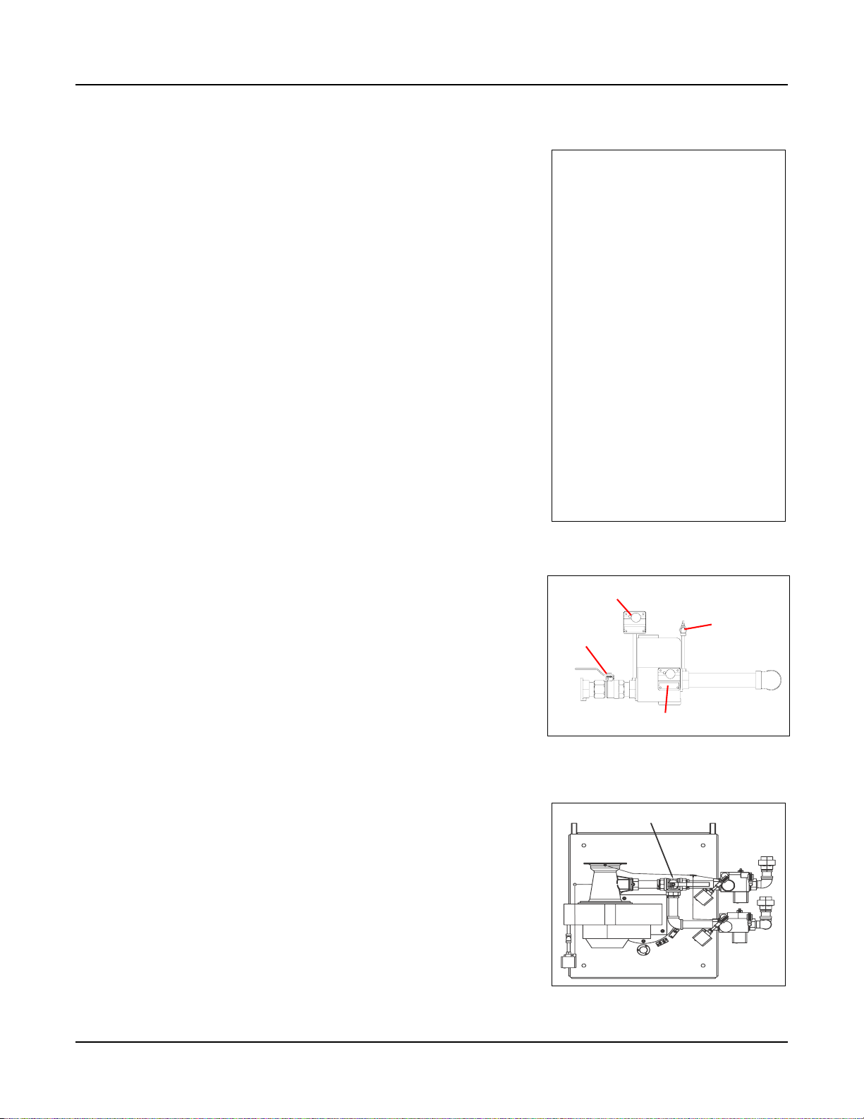
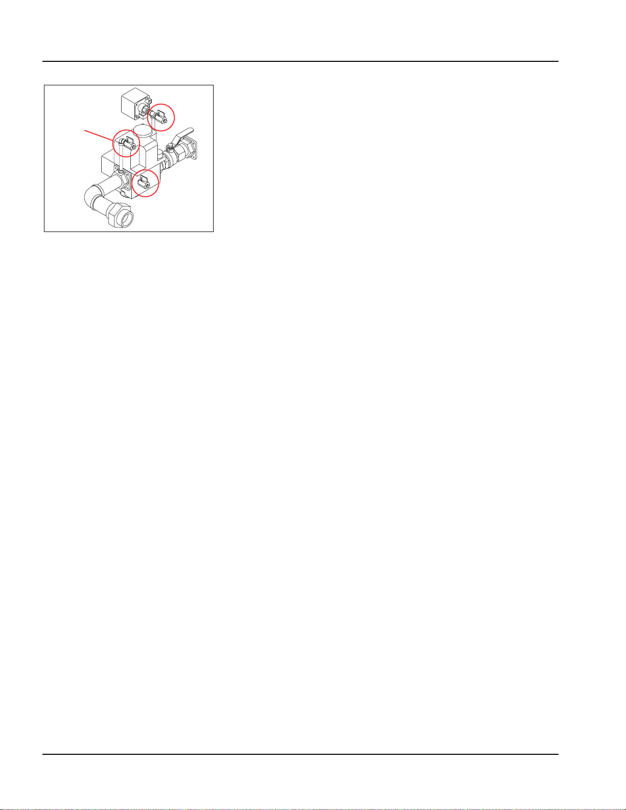
3. Burner Gas Train (See Figure 1-5 & Figure 1-6)
The gas train assembly is provided in accordance with UL
certification and complies with ASME CSD-1. The gas train
assembly is factory assembled and wired, consisting of the
following components:
A. Low Gas Pressure Switch - manual reset
B. High Gas Pressure Switch - manual reset
C. Single body, dual safety shutoff gas valve with integral trim
regulator
D. Integral Venturi
E. Manual Shutoff Ball Valve
F. C S D -1 T e s t C o c k s
High Gas Pressure Switch
Test Coc k
Manual Shutoff
Low Gas Pressure Switch
Figure 1-5 Standard Gas Train
Gas Shutoff / Selector Valve
Natural
Gas Train
Propane
Gas Train
Figure 1-6 Optional dual gas train
Part No. 750-263 1-3
Page 10
Section 1 — Introduction
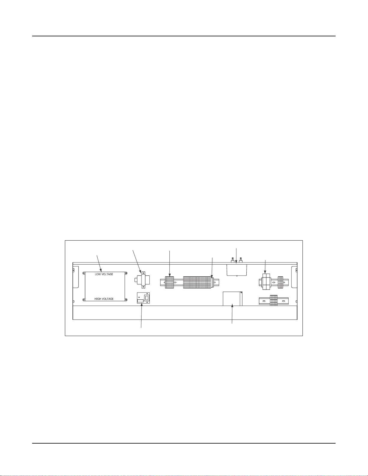
4. Control (See Figure 1-7)
The CB Falcon hydronic control is an integrated burner management
and modulation control with a touch-screen display/operator
interface.
The controller is capable of the following functions:
• Two (2) heating loops with PID load control.
• Burner sequencing with safe start check, pre-purge,
direct spark ignition, and post purge.
• Electronic ignition.
• Flame Supervision.
• Safety shutdown with time-stamped display of lockout
condition.
• Variable speed control of the combustion fan.
• Supervision of low and high gas pressure, air proving,
stack back pressure, high limit, and low water.
• First-out annunciator.
• Real-time data trending.
• (3) pump/auxiliary relay outputs.
• Modbus communication capability.
• Outdoor temperature reset.
• Remote firing rate or setpoint control
• Setback/time-of-day setpoint
• Lead/Lag for up to 8 boilers
CB Falcon
Controller
Transformer
LWCO
Control Board
Terminal Strip
Fuse Block
Figure 1-7 Control panel interior
Ignition Transformer
Blower & Control
Circuit Fuses
Power Supply
1-4 Part No. 750-263
Page 11

5. Component/Connection Locations
Figure 1-8 shows the CFC component orientation and heat flow
path. Note the downfired design of the burner and the orientation of
the hot water outlet and return connections. The return water
connection is at the bottom of the vessel and the hot water outlet is
near the top.
Figure 1-9 shows the locations of the safety valve and low water
cutoff. Figure 1-10 shows the location of the return water
temperature sensor. Looking at the top of the boiler, near the rear,
Figure 1-11 shows the three hole sensor well for the outlet
temperature sensor.
When standing at the back of the boiler, the stack can be connected
on the right side of the boiler (Figure 1-12) or on the left side. Refer
to Chapter 3 of this manual for recommended vent sizes and lengths
for the specific boiler installation.
6. Optional Equipment
Certain project-specific options may have been supplied with the
boiler if these options were specified at the time of order entry. In
addition, some options may have been provided (by others) that are
not part of Cleaver-Brooks’ scope of supply. In either case, the
Cleaver-Brooks authorized representative should be consulted for
project specifics.
Section 1 — Introduction
These are the options that are available for the CFC boiler from
Cleaver-Brooks:
A. Dual gas train for quick and easy fuel switchover.
B. Reusable air filter.
C. Condensate neutralization tank assembly - consists of
neutralizing media, filter, and PVC condensate holding tank
with integral drain trap. This assembly is mounted beneath
the boiler and is further described in Chapter 2.
D. Outside air intake for direct vent combustion.
E. Outdoor temperature sensor for indoor/outdoor control.
F. Header temperature sensor for multiple boiler Lead/Lag
operation.
G. Auxiliary Low Water Control (shipped loose) for field piping
by others into the system piping.
H. Alarm Horn for safety shutdown.
I. Relays for output signal for burner on, fuel valve open.
J. Stack Thermometer.
K. Stack temperature limit-sensor.
L. Auto air vent.
M. Boiler drain valve.
Part No. 750-263 1-5
Page 12

Section 1 — Introduction
Safety Relief Valve
Hot Water
Outlet
Combustion Fan and
Premix Gas Valve
Assembly
Ignition Electrodes
Flame Rod
and
Burner
Canister
Control
Panel
High Temp.
Return
Low Temp.
Return
Flue Gas
Outlet
“Finned” High
Efficiency AluFer
Tubes
Insulation Blanket
Figure 1-8 CFC Heat Flow and Component Orientation
1-6 Part No. 750-263
Page 13

Section 1 — Introduction
Auto air vent
(optional; shipped
loose)
Safety Valve
(shipped loose)
Low Water Cutoff
Probe
Figure 1-9 Boiler Controls
Figure 1-10 Return Temperature Sensor Mounting
Part No. 750-263 1-7
Page 14

Section 1 — Introduction
Figure 1-11 Outlet Temperature Sensor, Top of Pressure Vessel
The stack can be mounted on the right (Figure 1-12) or left side on
the back of the boiler base.
The flue gas duct sizes may be reduced at the vent connection.
See also Chapter 4 - Stack and Intake Vent Sizing and Installation.
Figure 1-12 Stack Right Side
(viewed from rear)
.
1-8 Part No. 750-263
Page 15

Section 2
Installation
Assembly . . . . . . . . . . . . . . . . . . . . . . . . . . . . . . . . . . . . . . . . . . . . 2-3
Packaging . . . . . . . . . . . . . . . . . . . . . . . . . . . . . . . . . . . . . . . . . . 2-3
Boiler placement . . . . . . . . . . . . . . . . . . . . . . . . . . . . . . . . . . . . . . 2-3
Casing assembly . . . . . . . . . . . . . . . . . . . . . . . . . . . . . . . . . . . . . . 2-4
Flue gas/combustion air connections. . . . . . . . . . . . . . . . . . . . . . . . . 2-10
Water treatment . . . . . . . . . . . . . . . . . . . . . . . . . . . . . . . . . . . . . . . 2-11
Using glycol. . . . . . . . . . . . . . . . . . . . . . . . . . . . . . . . . . . . . . . . . . 2-12
Boiler room . . . . . . . . . . . . . . . . . . . . . . . . . . . . . . . . . . . . . . . . . . 2-14
Gas connections . . . . . . . . . . . . . . . . . . . . . . . . . . . . . . . . . . . . . . 2-15
General . . . . . . . . . . . . . . . . . . . . . . . . . . . . . . . . . . . . . . . . . . . 2-15
Gas train components . . . . . . . . . . . . . . . . . . . . . . . . . . . . . . . . . 2-15
Gas pressure requirements . . . . . . . . . . . . . . . . . . . . . . . . . . . . . 2-15
Gas piping . . . . . . . . . . . . . . . . . . . . . . . . . . . . . . . . . . . . . . . . . 2-16
Gas supply pipe sizing . . . . . . . . . . . . . . . . . . . . . . . . . . . . . . . . 2-17
Gas header . . . . . . . . . . . . . . . . . . . . . . . . . . . . . . . . . . . . . . . . 2-20
Boiler water piping . . . . . . . . . . . . . . . . . . . . . . . . . . . . . . . . . . . . . 2-22
General . . . . . . . . . . . . . . . . . . . . . . . . . . . . . . . . . . . . . . . . . . . 2-22
Safety valve . . . . . . . . . . . . . . . . . . . . . . . . . . . . . . . . . . . . . . . . 2-22
Pressure drop curves . . . . . . . . . . . . . . . . . . . . . . . . . . . . . . . . . . 2-22
Condensate removal and treatment. . . . . . . . . . . . . . . . . . . . . . . . . . 2-29
Condensate tank setup options . . . . . . . . . . . . . . . . . . . . . . . . . . 2-30
Condensate piping for multiple boilers . . . . . . . . . . . . . . . . . . . . . 2-31
Electrical connections . . . . . . . . . . . . . . . . . . . . . . . . . . . . . . . . . . . 2-32
Wiring diagrams . . . . . . . . . . . . . . . . . . . . . . . . . . . . . . . . . . . . . . . 2-34
Milwaukee, Wisconsin
www.cleaver-brooks.com
Page 16
Section 2 — Installation
Warning
!
Provisions for combustion and ventilation air must
be in accordance with the National Fuel Gas
Code, ANSI Z223.1, or the CAN/CSA B149
Installation Codes, or applicable provisions of the
local building codes. Failure to follow this warning
could result in personal injury or death.
Warning
!
If an external electrical source is utilized, the boiler
when installed must be electrically bonded to
ground in accordance with the requrements of the
authority having jurisdiction, or in the absence of
such requirements with the National Electrical
Code ANSI/NFPA 70 and/or the Canadian
Electrical Code Part I CSA C22.1.
Caution
The boiler must be installed such that the gas
ignition system components are protected from
water (dripping, spraying, rain, etc.) during
appliance operation and sevice. Failure to follow
this warning could result in equipment failure.
Warning
!
The installation must conform to the requirements of the authority having jurisdiction, or in
the absence of such requirements, to the
National Fuel Gas Code, ANSI Z223.1 and/or
CAN/CSA B149 Installation Codes.
2-2 Part No. 750-263
Page 17
A. ASSEMBLY
1. Packaging
The Cleaver-Brooks Model CFC boiler is shipped in three parcels.
The pressure vessel assembly mounted on a skidded crate, the
control panel in a box, and the outer casing with insulation in a
skidded box. It is recommended that the pressure vessel be properly
mounted with all piping connections attached prior to installation of
the casing.
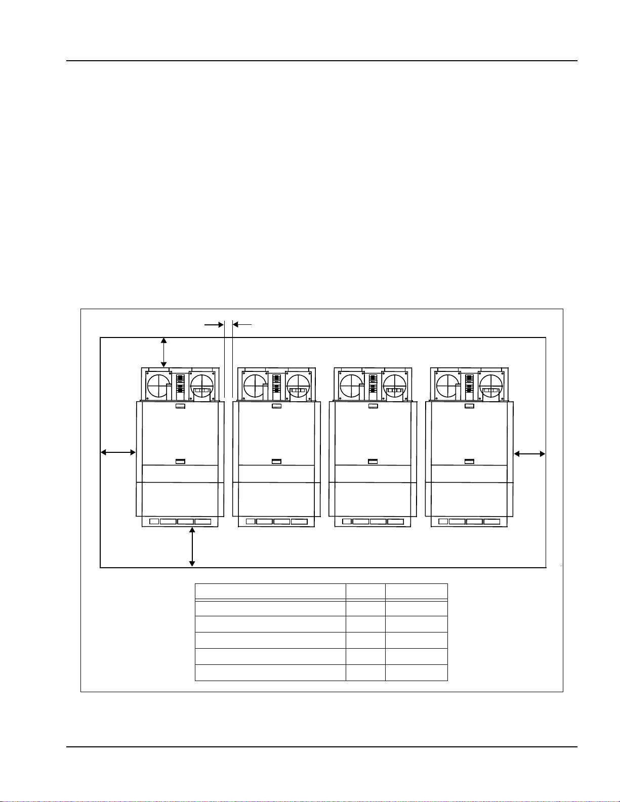
2. Boiler placement
The boiler or boilers should be mounted in a space in accordance
with Figure 2-1 below. Required front, rear, and side clearances are
shown.
Note:If the boiler room is constructed with non-combustible
walls, it is possible to install the units closer to the side
walls, but the front and rear clearances must be
maintained.
S
E
Section 2 — Installation
C
B
D
DIM Inches
Top Clearance A 14
Side Clearance B 20
Backway C 20
Front D 36
Between Boilers E 3
B
Figure 2-1 Clearance Required
Part No. 750-263 2-3
Page 18
Section 2 — Installation
3. Casing assembly
To assemble the CFC casing, the following tools are required:
Figure 2-2
Flat head screwdriver
Phillips screwdriver
Cordless screwdriver
Utility knife
Crescent wrench
Machine head screw bit
Diagonal cutters
Socket wrench
10mm socket
13mm socket
19mm socket
6” socket extension
Zip-ties
Sheet metal screws
Fork lift or pallet jack
1. Remove all packing material and open all boxes shipped with the boiler.
2. Remove all casing panels from box and group like pieces together for easy
access.
3. Locate boiler legs and attaching nuts/bolts (Figure 2-2). Ensure all four
leg height adjusters are at the same level before installing legs.
4. Remove the wooden skid cross beam from the front of the boiler
5. Using an appropriate jack, lift up the front of the boiler.
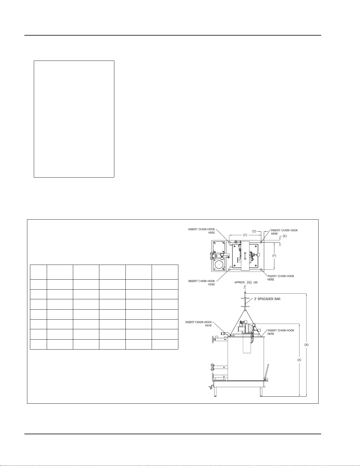
Note: A crane or fork lift may also be used to lift the boiler. When using a
crane, observe the rigging arrangement shown in Figure 2-3. To install
the boiler legs, first lift boiler, then remove and discard the wooden
base. Install legs and position the boiler. Proceed with step 10 below.
CFC
SIZE
500/750 1000 1500 1800 2500
A 70.625” 82.875” 74.875” 82” 84”
B 118.625” 130.875” 122.875” 130” 132”
C 20.5” 33.5” 32.625” 32.625 37.375”
D 3.15” 1.97” 2.76” 2.76 3.94”
E 3.15” 1.97” 2.76” 2.76 3.94”
F 20.5” 33.5” 32.625 32.625 37.375”
G 1477 lbs 1554 lbs 1940 lbs 2061 lbs 3600 lbs
Figure 2-3 CFC Standard Rigging Arrangement
2-4 Part No. 750-263
Page 19
6. Attach the boiler front legs.
7. Lift up the back of the boiler using the jack and remove the wooden skid
side beams.
8. Attach the rear boiler mounting legs.
9. Lifting eyes are provided for moving and positioning the boiler.
10.Before installing insulation, level the boiler using a level placed against
the side of the vessel.
11.Wrap insulation blanket around pressure vessel. Ensure all pre-cut holes
fit completely over boiler fittings (Figure 2-4) and blanket is snug to the
vessel.
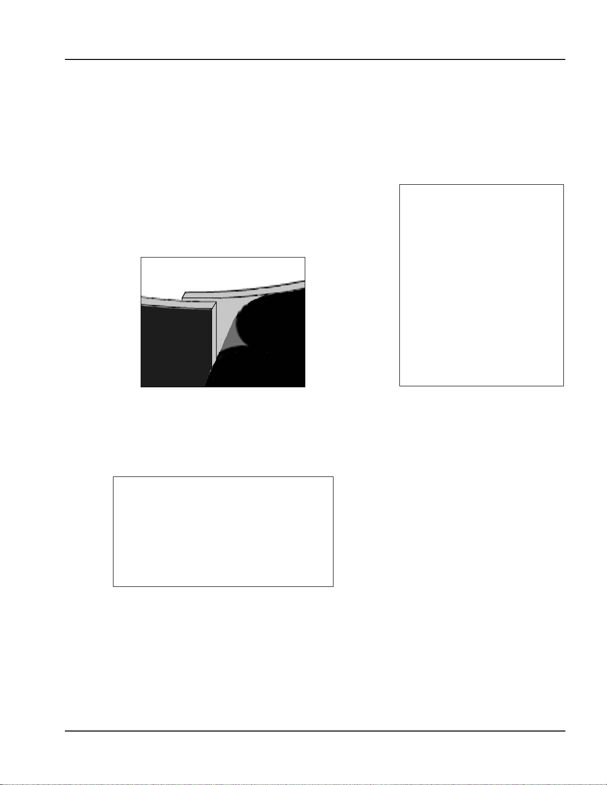
12.Peel backing from any excess length of insulation. Tuck excess portion
under other end of blanket. Place backing over overlapping segments
(Figure 2-5) and proceed with step 13.
Section 2 — Installation
Figure 2-5
13.Use tension springs to hold edges of blanket together. Poke end of spring
through the fabric of the insulation blanket (Figure 2-6). Place one spring
at the top and one at the bottom of the blanket. Place the remaining two
springs equally spaced.
Figure 2-6
14.Fit one end of black plastic strap to the fastener (Figure 2-7). Wrap strap
around the boiler and connect other end to fastener. Repeat with second
strap. Tighten straps so blanket is snug, but do not overtighten. Do not
compress insulation. Position the straps at ¼ and ¾ height.
Figure 2-4
Part No. 750-263 2-5
Page 20
Section 2 — Installation
Figure 2-7
15.Using a 10mm socket, or by hand, remove 3 nuts and washers from the
mounting studs extending from each side of the top plate of the boiler
(Figure 2-8).
Figure 2-8
16.Attach electrical supply channels on each side (Figure 2-9).
Figure 2-9
17.Attach large side panels to each side, fitting on top of the electrical
supply channel. Fasten loosely, using nuts and washers previously
removed. Do not over tighten. You will need these panels to move
slightly to fit the other pieces. See Figure 2-10.
2-6 Part No. 750-263
Page 21

Figure 2-10
Section 2 — Installation
18.Remove control panel from box. Uncoil sensor wires and route wires out
of left-hand side of panel.
19.Mount control panel on front of boiler (Figure 2-11). Make sure to route
sensor wires in wiring channel on left-hand side of the boiler (see also
Figure 2-41).
Figure 2-11
20.Connect control wiring (Figure 2-12):
• Connect flame rod cable (A) to stand alone electrode on right
(includes burner ground connection).
• Connect ignition cables (B) to dual igniter electrode.
• Connect remaining connectors per connection diagram (see
Figure 2-41).
Part No. 750-263 2-7
Page 22
Section 2 — Installation
B
A
Figure 2-12
21.Route return water sensor (the 2-wire sensor) to the lower pipe on back
of boiler, and install lower panel. Coat sensor with heat-conductive
compound P/N 872-00631. Insert sensor into return pipe sensor well
and secure with mounting clamp (Figure 2-13).
Figure 2-13
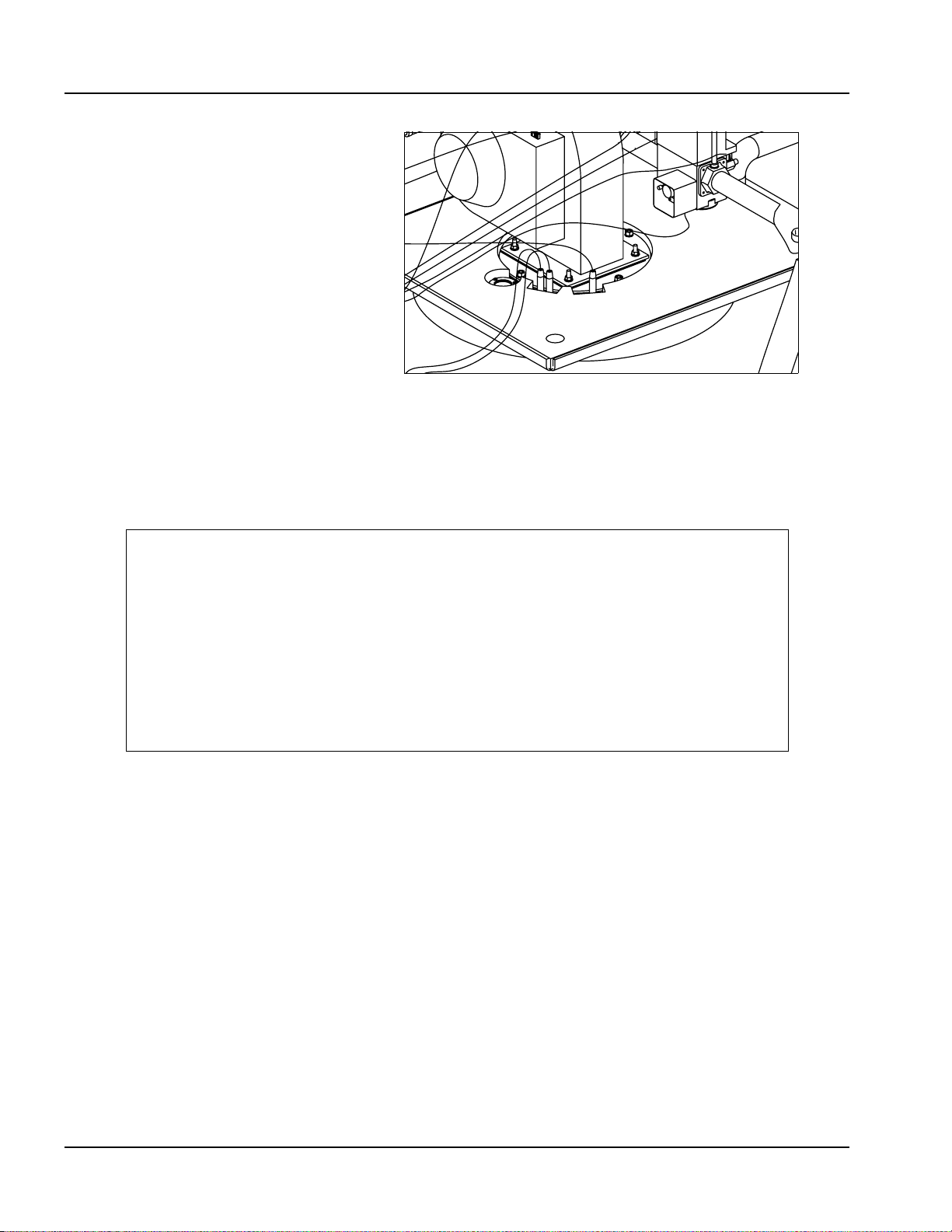
22.Coat outlet feed water temperature sensor (the 3-wire sensor) with heatconductive compound P/N 872-00631. Insert sensor in sensor well
behind the burner (Figure 2-14).
2-8 Part No. 750-263
Page 23

Figure 2-14
23.Install rear center panels (Figure 2-15).
Section 2 — Installation
Figure 2-15
24.Install C-clips on upper side panels, then install panels on boiler (Figure
2-16).
25.Install top rear panel and top center panel.
26.Attach side skirt panels to boiler legs using the supplied cap nuts (Figure
2-17).
Figure 2-16
Part No. 750-263 2-9
Page 24

Section 2 — Installation
Figure 2-17
27.Attach front skirt panel to the side panels.
28.Install front panel.
Assembly is now complete.
Figure 2-18
B. FLUE GAS / COMBUSTION AIR CONNECTIONS
The flue gases from the Model CFC boiler should be removed via a
gas-tight, temperature and corrosion resistant flue gas pipeline.
Only flue gas systems approved and tested by the relevant region or
province are to be connected to the boiler. Refer to flue piping
2-10 Part No. 750-263
Page 25
manufacturer for proper installation and sealing instructions. See
also Chapter 3 of this manual for combustion air and flue gas
venting requirements.
C. WATER TREATMENT
Cleaver-Brooks ClearFire condensing boilers are suitable for heating
systems without significant oxygenation capacity. Systems with
continuous oxygenation capacity due to unknown or unseen leaks
must be equipped with a system separation or pretreatment device.
Untreated drinking water is generally the best heating medium as
filling and make-up water for a system that utilizes the Model CFC.
If the water available from the main system is not suitable for use,
then demineralization and/or treatment with inhibitors is necessary.
Treated filling and make-up water must be checked at least once a
year or more frequently if so specified in the application guidelines
from the inhibitor manufacturer.
Those parts of the boiler in contact with water are manufactured
with ferrous materials and corrosion-resistant stainless steel. The
chloride content of the heating water must not exceed 30 mg/l and
the pH level should be between 8.3 to 9.5 after six weeks of
operation.
Section 2 — Installation
To maintain the boiler's efficiency and prevent overheating of the
heating surfaces, the values in Tab le 2- 1 should not be exceeded.
Water make-up during the lifetime of the boiler should not be
greater than 3 times the system volume. A water meter should be
installed on the feed line to monitor makeup water volume.
Following production of the pressure vessel, the interior surfaces are
cleaned and therefore a pre-start boil out of the vessel is not
needed. Should the system require boil out or cleaning after
installation of the CFC, take care that no particulate matter reaches
the boiler during the cleaning process. A removable filter should be
used for this purpose.
Notice
Corrosion and sludge deposits in old systems must be removed prior
to installation of a new boiler.
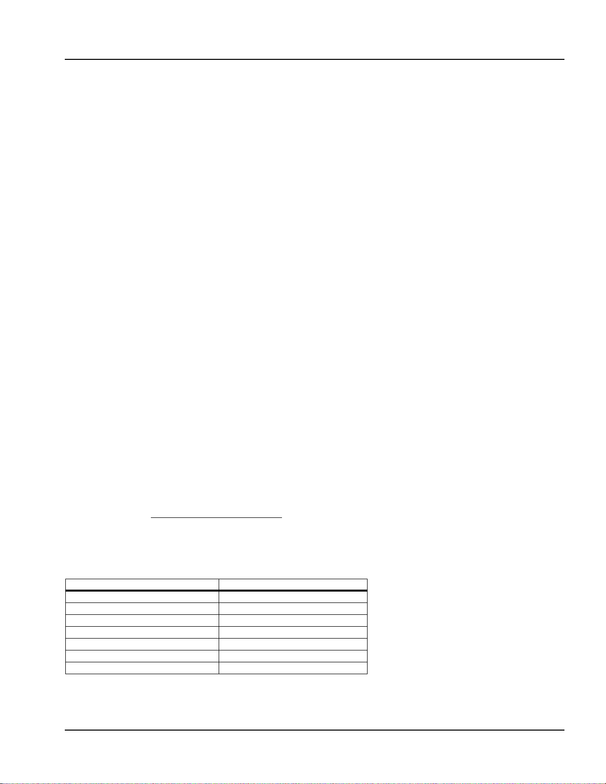
Table 2-1 Model CFC Water Chemistry
Parameter Limit
pH 8.3 - 9.5
Chloride 30 mg/liter
Nitrates 50 mg/liter
Sulphates 50 mg/liter
Oxygen 0.1 mg/liter
Specific Conductivity 3500 umho/cm
Total Hardness <10 ppm
Part No. 750-263 2-11
Page 26

Section 2 — Installation
T able 2-2 Model CFC Water Temperature Data (Non-Glycol)
Minimum supply temp. 33oF
Maximum operating temp. 194oF
o
Maximum design temp. 210
F
D. USING GLYCOL
The Model CFC boiler may be operated with a solution of glycol and
water. Where glycols are added, the system must first be cleaned
and flushed. Correct glycol selection and regular monitoring of the
in-use concentration and its stability is essential to ensure
adequate, long-term freeze protection, including protection from the
effects of glycol-derived corrosion resulting from glycol degradation.
Typically, ethylene glycol is used for freeze protection, but other
alternatives exist, such as propylene glycol. Glycol reduces the
water-side heat capacity (lower specific heat than 100% water) and
can reduce the effective heat transfer to the system. Because of
this, design flow rates and pump selections should be sized with
this in mind.
Generally, corrosion inhibitors are added to glycol systems.
However, all glycols tend to oxidize over time in the presence of
oxygen, and when heated, form aldehydes, acids, and other
oxidation products. Whenever inadequate levels of water treatment
buffers and corrosion inhibitors are used, the resulting water glycol
mixture pH may be reduced to below 7.0 (frequently reaching 5)
and acid corrosion results. Thus, when pH levels drop below 7.0
due to glycol degradation the only alternative is to drain, flush,
repassivate, and refill with a new inhibited glycol solution.
The following recommendations should be adhered to in applying
ClearFire model CFC boilers to hydronic systems using glycol:
1) Maximum allowable antifreeze proportion (volume %):
50% antifreeze (glycol)
50% water
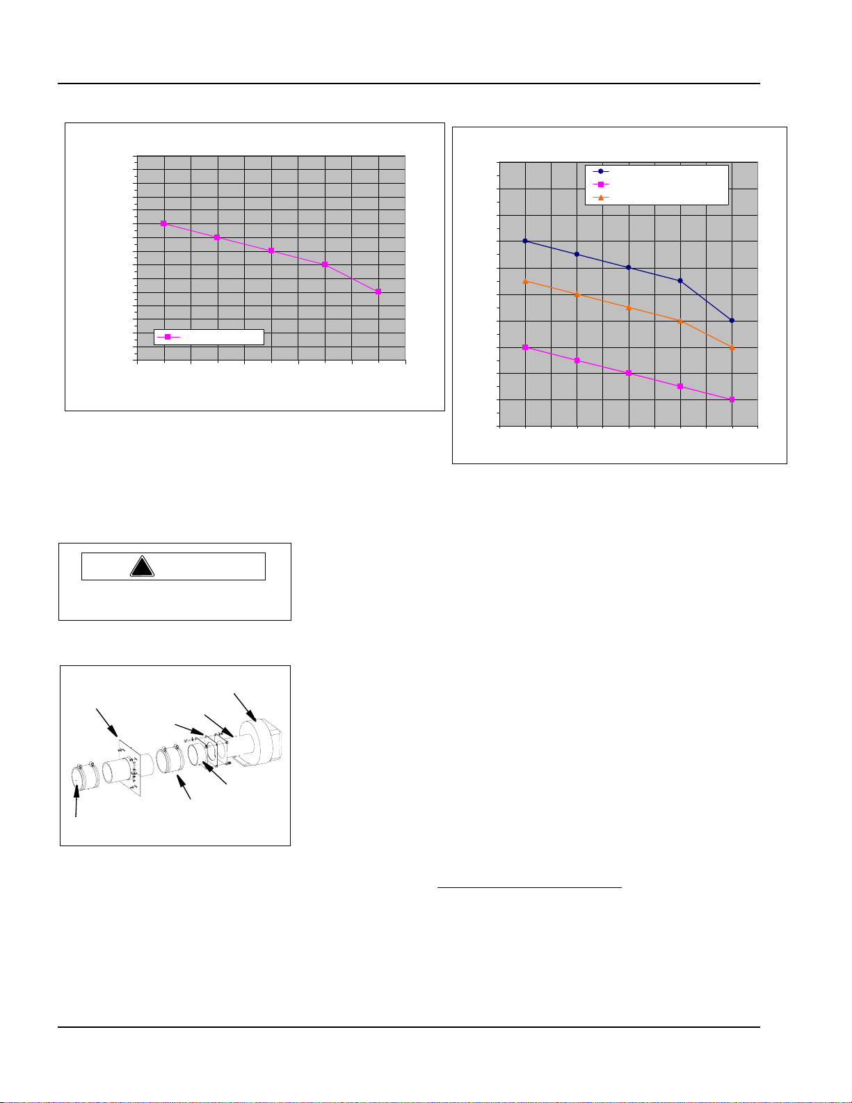
2) The glycol concentration determines the maximum allowable firing
rate and output of the boiler(s). Please refer to the firing rate
limitation and corresponding high fire speed settings vs. glycol %
in the charts below.
3) Maximum allowable boiler outlet/supply temperature: 185 deg F
(85 deg C).
4) Minimum water circulation through the boiler:
a) The minimum water circulation must be defined in such a
way that the temperature difference between the boiler
outlet/supply and inlet/return is a maximum of 40 deg F
(22 deg C), defined as DT (Delta T). A DT Limit algorithm
should be enabled in the boiler controller.
b) Independent from the hydraulics of the heating system,
constant water circulation through each boiler is required.
(Requires a dedicated boiler pump if in a primary/
2-12 Part No. 750-263
Page 27
Section 2 — Installation
secondary loop arrangement.) Refer to table below for
minimum boiler circulation rates.
5) Minimum over-pressure at the boiler:
For outlet temperatures up to the maximum of 185 deg F (85 deg
C), a minimum operating pressure of 30 psig (2.1 bar) is required.
6) pH level should be maintained between 8.3 and 9.5
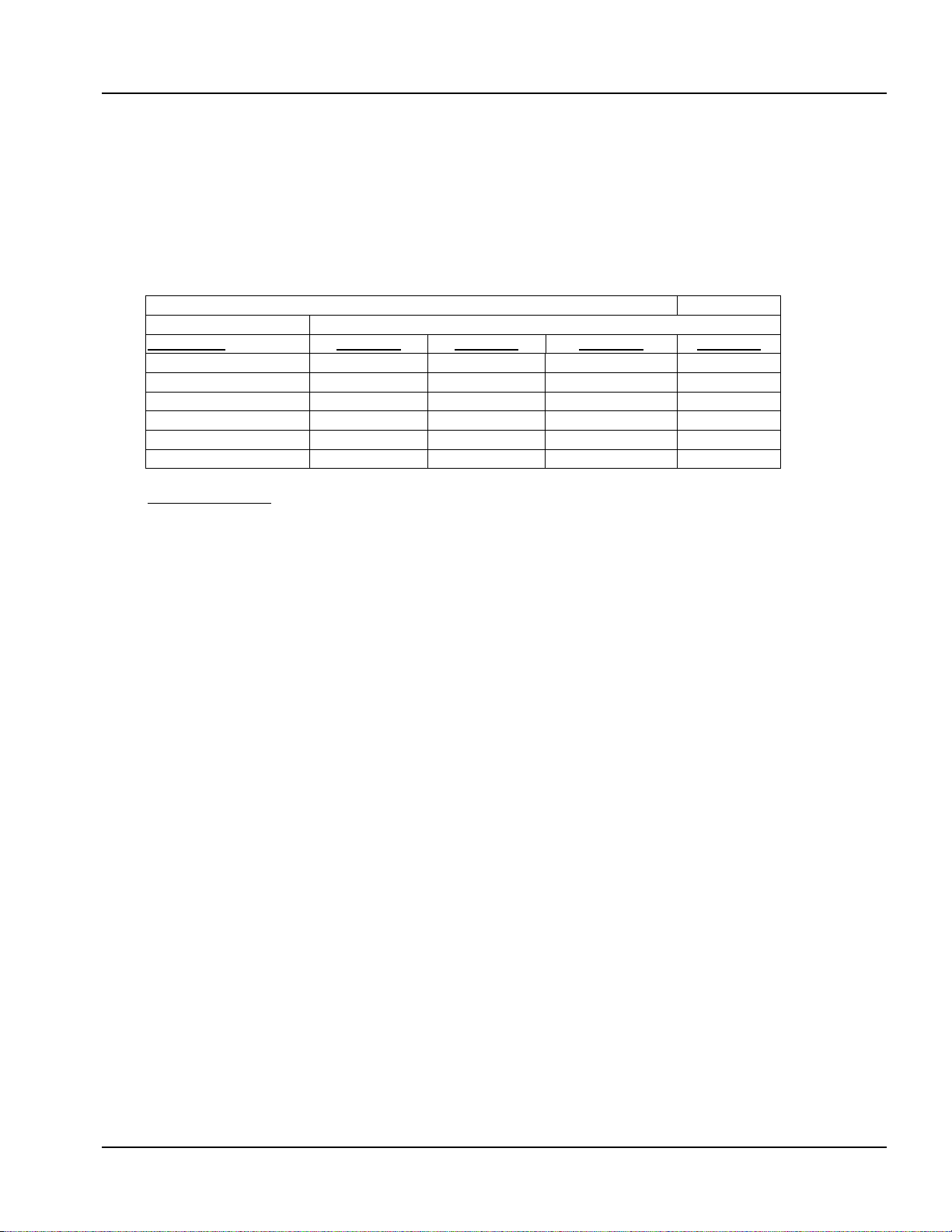
Glycol Application Guidelines — ClearFire Model CFC
Minimum required boiler circulation rate (gpm) at maximum firing rate.
ClearFire System ΔT (˚F)
Model-Size
CFC-500 88 44 29 22
CFC-750 131 66 44 33
CFC-1000 175 88 58 44
CFC-1500 263 131 88 66
CFC-1800 316 158 105 79
CFC-2500 438 219 146 110
Notes/Limitations:
1. Maximum firing rate determined by ClearFire CFC - Glycol Firing Rate Limitation chart (below).
Maximum high fire blower speed should be set according to chart.
2. Glycol concentration limit of 25%-50%. Minimum required system operating pressure is 30
psig.
3. Maximum system operating temp er at ur e of 180 ˚F. Maximum ΔT of 40˚.
4. Circulation rates correlate with boiler output based on 92% nominal efficiency.
5. Standard altitude (<1000' ASL). Contact C-B for high altitude applications.
6. Pumps should be sized based on system design ΔT and minimum required flow rates.
7. At minimum firing rate, the minimum circulation rate should correspond to the boiler's turndown.
ΔT = 10˚ ΔT = 20˚ ΔT = 30˚ ΔT = 40˚
Part No. 750-263 2-13
Page 28
Section 2 — Installation
CFC - Maximum Firing Rat e vs. Glycol Concentr ation
100%
98%
96%
94%
92%
90%
88%
86%
84%
82%
80%
78%
Maxi m um I nput Rat e %
76%
74%
72%
Max Firing Rate %
70%
25% 30% 35% 40% 50%
Glycol Content
Warning
!
The boiler must not be installed
on carpeting.
CFC - High Fire Speed Setting vs % Glycol
High Fire Speed (RPM)
5400
5200
5000
4800
4600
4400
4200
4000
3800
3600
3400
25% 30% 35% 40% 50%
CFC-500/750/1000/1500 - HF RPM
CFC-1800 - HF RPM
CFC-2500 - HF RPM
Glycol Content
E. BOILER ROOM
The boiler room must comply with all building codes and
regulations. An adequate supply of combustion air is required for
safe operation. If the optional direct vent combustion air kit (Figure
2-19) is not used, ventilation must be provided to meet applicable
regulations for air supply.
Casing Support
Attachment
Gasket
Flexible Connection
Direct Vent Connection
Fan/Blower
Venturi
Adapter Flange
Figure 2-19 Air Inlet Extension
Notice
See Section 6, Parts, for part numbers for the Direct Vent
Combustion Air kits available.
2-14 Part No. 750-263
Page 29
Clean combustion air is required for optimum efficiency and boiler
operation. Dust and airborne contaminants will adversely effect
burner performance. If conditions dictate, a serviceable filter must
be placed in the intake piping to eliminate airborne contamination
to the burner. An optional air filter is available from Cleaver-Brooks.
Additionally, if a direct vent combustion air intake vent is used the
intake should be directed to eliminate rain or snow from entering the
intake piping. The boiler must be installed so that the gas ignition
system components are protected from water (dripping, spraying,
etc.) during appliance operation and service.
F. GAS CONNECTIONS
1. General
The ClearFire Model CFC gas fired condensing boilers are full
modulating input units that require appropriate gas supply pressure
and volume for proper operation. The gas requirements specified in
this section must be satisfied to ensure efficient and stable
combustion. Installation must follow these guidelines and those of
any local authorities having installation jurisdiction.
Gas
Connection
Section 2 — Installation
Air Inlet
Extension
Hot
Water
Out
High
Temp.
Return
Low
Temp.
Return
2. Gas Train Components
CFC boilers are equipped with a gas train that meets the
requirements of ASME CSD-1, FM and XL-GAP (formerly IRI). The
gas train and its components have been designed and tested to
operate for the highest combustion efficiency for the CFC units.
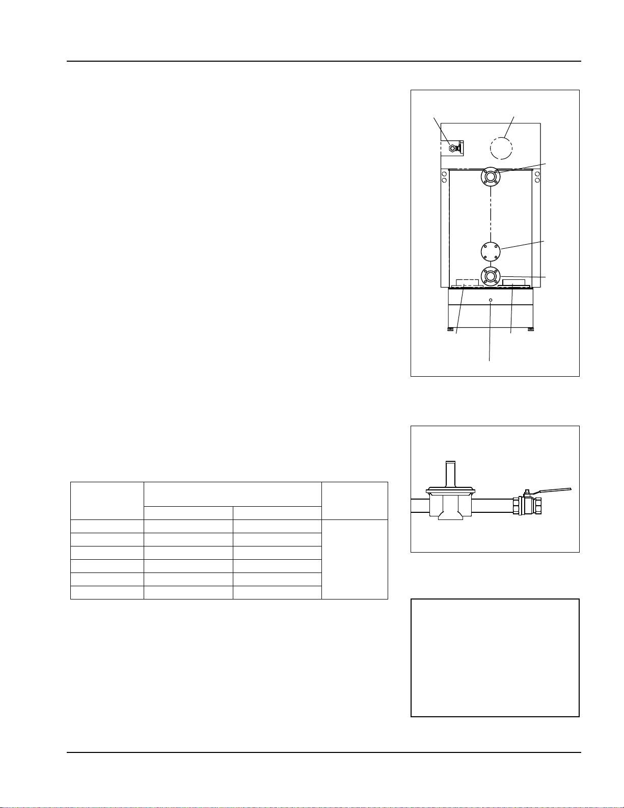
3. Gas Pressure Requirements
For proper and safe operation, each CFC Series boiler requires a
stable gas pressure input. See Ta bl e 2 -3 for pressure requirements.
Table 2-3 Model CFC Gas Pressure Requirements
Minimum pressure required at gas train
Boiler Model
500 7" w.c. 11" w.c.
750 7" w.c. 11" w.c.
1000 7" w.c. 11" w.c.
1500 10" w.c. 11" w.c.
1800 7" w.c. 11" w.c.
2500 9.5" w.c. 11" w.c.
Actual gas pressure should be measured when the burner is firing
using a manometer at the upstream test port connection on the
main gas valve. For a multiple unit installation, gas pressure should
be set for a single unit first, then the remaining units should be
staged on to ensure that gas pressure drop is not more than 1" w.c.
and never below the required pressure. Fluctuating gas pressure
readings could be indicative of a faulty supply regulator or improper
gas train size to the boiler.
connection
Natural Gas LP Gas
Max. pressure
28” w.c.
Alternate
Flue Gas
Condensate Drain
Flue Gas
Vent Connection
Figure 2-20 CFC Rear View
Gas Pressure Regulator
Shutoff Valve
Figure 2-21 Gas Regulator and
Shutoff Valve (typical)
NOTE: The pressure test port is
located at the gas valve inlet
flange (see Figure 2-22). The
remaining test cocks are for leak
test purposes and should not be
used to measure gas pressure.
Refer to
INSTALLATION AND MAINTENANCE
APPENDIX C - GAS VALVE
for more information.
Part No. 750-263 2-15
Page 30
Section 2 — Installation
Leak Test
Pressure
Test
Leak Test
Figure 2-22 Test cocks - gas
valve
4. Gas Piping
CFC units are not standardly equipped with an upstream gas
pressure regulator. Therefore, a regulator must be installed at each
CFC unit. Do not use a common regulator to regulate pressure for a
multiple unit installation. Note: Gas connection is at the rear of the
boiler, left hand side as you face the rear of the boiler.
If local code permits, a flexible connection can be used between the
gas line and gas valve. This will enable the burner door to be opened
without disconnecting the gas line.
The regulator for each boiler must be installed with at least 2 feet of
pipe between the regulator and the boiler gas train connection. The
discharge range of the regulator must be able to maintain gas
pressures as noted in Tab le 2 - 3 .
For buildings or boiler rooms with gas supply pressure exceeding 28"
w.c. a "full lock-up" type regulator is required as well as overpressure
protection (e.g. relief valve).
In addition to the regulator, a plug type or "butterball” type gas
shutoff valve must be installed upstream of the regulator for use as a
service valve. This is also required to provide positive shutoff and
isolate the unit during gas piping tests.
If necessary a strainer should be installed upstream of the regulator
to remove debris from the gas supply.
Drip legs are required on any vertical piping at the gas supply to
each boiler so that any dirt, weld slag, or debris can deposit in the
drip leg rather than into the boiler gas train. The bottom of the drip
leg should removable without disassembling any gas piping. The
connected piping to the boiler should be supported from pipe
supports and not supported by the boiler gas train or the bottom of
the drip leg. Do not pipe across the top of the boiler as the burner
swings up for service and must have proper clearance.
All gas piping and components to the boiler gas train connection
must comply with NFPA 54, local codes, and utility requirements as
a minimum. Only gas approved fittings, valves, or pipe should be
used. Standard industry practice for gas piping is normally Schedule
40 black iron pipe and fittings.
Before starting the unit(s) all piping must be cleaned of all debris to
prevent its entrance into the boiler gas train. Piping should be tested
as noted in NFPA 54 and the boiler must be isolated during any
tests.
After initial startup, the inlet screen to the gas valve should be
checked and cleaned of any debris buildup.
See Figure 2-23 for a typical piping configuration.
2-16 Part No. 750-263
Page 31

Caution
!
The boiler and its individual shutoff valve must be disconnected
from the gas supply piping system during any pressure testing of
that system at test pressures in excess of 1/2 psi (3.5 kPa).
The boiler must be isolated from the gas supply piping system by
closing its individual manual shutoff valve during any pressure
testing of the gas supply piping system at test pressures equal to
or less than 1/2 psi (3.5 kPa).
5. Gas Supply Pipe Sizing
For proper operation of a single unit or a multiple unit installation,
we recommend that the gas piping be sized to allow no more than
0.3" w.c. pressure drop from the source (gas header or utility meter)
to the final unit location. Higher supply pressure systems may allow
for a greater pressure drop. In ALL cases, minimum supply pressures
must be met for proper operation of the boiler(s). The gas supplier
(utility) should be consulted to confirm that sufficient volume and
normal pressure are provided to the building at the discharge side
of the gas meter or supply pipe.
Section 2 — Installation
For installations of new boilers into an existing building, gas
pressure should be measured with a manometer to ensure sufficient
pressure is available. A survey of all connected gas-using devices
should be made. If appliances other than the boiler or boilers are
connected to the gas supply line, then a determination must be
made of how much flow volume (cfh) will be demanded at one time
and the pressure drop requirement when all appliances are firing.
The total length of gas piping and all fittings must be considered
when sizing the gas piping. Total equivalent length should be
calculated from the utility meter or source to the final unit
connection. As a minimum guideline, see gas piping Tables 2-4 and
2-5. The data in these tables is from the NFPA 54 source book,
2006 edition.
To verify the input of each device that is connected to the gas piping,
obtain the btu/hr input and divide this input by the calorific value of
the gas that will be utilized. For instance, a unit with 750,000 btu/
hr input divided by a gas calorific value of 1060 will result in a cfh
flow of 707. The single boiler is approximately 20 feet from the gas
supply header source. And with a measured gas supply pressure of
10" w.c. we find from Tab l e 2 - 4 that a supply pipe size of 1-1/4"
should be used as a minimum.
Part No. 750-263 2-17
Page 32

Section 2 — Installation
Nominal 1" 1-1/4" 1-1/2" 2" 2-1/2" 3" 4"
Actual I.D. 1.0491.380" 1.610" 2.067" 2.469" 3.068" 4.026"
Length in feet **Maximum Capacity in Cubic Feet of Gas per Hour (cfh)
10 514 1,060 1,580 3,050 4,860 8,580 17,500
20 363 726 1,090 2,090 3,340 5,900 12,000
30 284 583 873 1,680 2,680 4,740 9,660
40 243 499 747 1,440 2,290 4,050 8,290
50 215 442 662 1,280 2,030 3,590 7,330
60 195 400 600 1,160 1,840 3,260 6,640
70 179 368 552 1,060 1,690 3,000 6,110
80 167 343 514 989 1,580 2,790 5,680
Table 2-4: Gas Line Capacity - Schedule 40 Metallic Pipe
Pipe Size
90 157 322 482 928 1,480 2,610 5,330
100 148 304 455 877 1,400 2,470 5,040
125 131 269 403 777 1,240 2,190 4,460
150 119 244 366 704 1,120 1,980 4,050
175 109 209 336 648 1,030 1,820 3,720
200 102 185 313 602 960 1,700 3,460
**Fuel: Natural Gas
**Inlet Pressure: Less than 2.0 psi
**Pressure Drop: 0.30" w.c.
**Specific Gravity: 0.60
2-18 Part No. 750-263
Page 33

Section 2 — Installation
Table 2-5: Gas Line Capacity - Schedule 40 Metallic Pipe
Pipe Size
Nominal 1" 1-1/4" 1-1/2" 2" 2-1/2" 3" 4"
Actual I.D. 1.049" 1.380" 1.610" 2.067" 2.469" 3.068" 4.026"
Length in feet **Maximum Capacity in Cubic Feet of Gas per Hour (cfh)
10 678 1,390 2,090 4,020 6,400 11,30023,10
0
20 466 957 1,430 2,760 4,400 7,780 15,90
0
30 374 768 1,150 2,220 3,530 6,250 12,70
0
40 320 657 985 1,900 3,020 5,350 10,90
0
50 284 583 873 1,680 2,680 4,740 9,600
60 257 528 791 1,520 2,430 4,290 8,760
70 237 486 728 1,400 2,230 3,950 8,050
80 220 452 677 1,300 2,080 3,670 7,490
90 207 424 635 1,220 1,950 3,450 7,030
100 195 400 600 1,160 1,840 3,260 6,640
125 173 355 532 1,020 1,630 2,890 5,890
150 157 322 482 928 1,480 2,610 5,330
175 144 296 443 854 1,360 2,410 4,910
200 134 275 412 794 1,270 2,240 4,560
**Fuel: Natural Gas
**Inlet Pressure: Less than 2.0 psi
**Pressure Drop: 0.50" w.c.
**Specific Gravity: 0.60
Part No. 750-263 2-19
Page 34

Section 2 — Installation
6. Gas Header
Design of a single common gas header with individual takeoffs for a
multiple unit installation is recommended. Boiler gas manifold
piping should be sized based on the volume requirements and
lengths between boilers and the fuel main header (see Figure 2-23).
Tab l es 2-6 to 2-11 indicate the proper sizing for multiple units of
equal size, placed on the factory standard center with the noted
take off size. For installations with a mixed sized use, determine the
flow of each unit and total the input. With the total input, determine
length of run from the source and determine what size header will
be needed for the flow of all units firing. Pipe sizes based on Tab le
2-4.
Table 2-6: Multiple Unit Manifold, CFC 500
CFC 500 Boilers
# of Units 1 2 3 4
Pipe Size to
Boiler
Header Pipe
size
1" 1" 1" 1"
1-1/4" 1-1/4" 1-1/2" 2"
Table 2-7: Multiple Unit Manifold, CFC 750
CFC 750 Boilers
# of Units 1 2 3 4
Pipe Size to
Boiler
Header Pipe
size
1" 1" 1" 1"
1-1/4" 1-1/2" 2" 2-1/2"
Table 2-8: Multiple Unit Manifold, CFC 1000 Table 2-9: Multiple Unit Manifold, CFC 1500
CFC 1000 Boilers
# of Units 1 2 3 4
Pipe Size to
Boiler
Header Pipe
size
1-1/4" 1-1/4" 1-1/4" 1-1/4"
1-1/4" 2" 2" 2-1/2"
CFC 1500 Boilers
# of Units 1 2 3 4
Pipe Size to
Boiler
Header Pipe
size
1-1/2" 1-1/2" 1-1/2" 1-1/2"
1-1/2" 2" 2-1/2" 3"
Table 2-10: Multiple Unit Manifold, CFC 1800 Table 2-11: Multiple Unit Manifold, CFC 2500
CFC 1800 Boilers
# of Units 1 2 3 4
Pipe Size to
Boiler
Header Pipe
size
2-20 Part No. 750-263
2" 2" 2" 2"
2" 2-1/2" 3" 3"
CFC 2500 Boilers
# of Units 1 2 3 4
Pipe Size to
Boiler
Header Pipe
size
2" 2" 2" 2"
2" 3" 3" 4"
Page 35

Figure 2-23 Gas Piping
Section 2 — Installation
Part No. 750-263 2-21
Page 36

Section 2 — Installation
G. BOILER WATER PIPING
1. General
All boiler hot water outlet and return piping is connected at the rear
of the boiler. Piping is to be installed per local codes and
regulations.The pipelines for the hot water outlet and return may be
connected in the usual manner without removing the cladding
elements. Unused connectors must be safely blanked off.
2. Safety valve
Pressure relief valve (Safety Valve) should be piped from the air vent
piping or hot water outlet pipe (see Figure 2-24). Use pipe sealing
compound and a flat sided wrench when securing the Safety relief
valve. Do not use a pipe wrench and do not over tighten the relief
valve. The safety valve must be mounted in a vertical position so
that discharge piping and code-required drains can be properly
piped to prevent buildup of back pressure and accumulation off
oreign material around the valve seat area. Apply only a moderate
amount of pipe compound to male threads and avoid
overtightening, which can distort the seats. Use only flat-jawed
wrenches on the flats provided.
Figure 2-24 Pressure Relief
Valve Piped to Safe Point of
Discharge
Warning
!
Only properly certified personnel such as the safety valve
manufacturer’s certified representative should adjust or repair the
boiler safety valve. Failure to follow this warning could result in
serious personal injury or death.
3. Dual return design
The Model CFC features separate high and low temperature return
water connections, allowing for condensing performance within
high temperature hydronic systems. With as little as 10% return
water at or below 120 deg F, the Model CFC will achieve condensing
performance, with associated gains in efficiency.
If using only a single (common) return, the lower return connection
should be used.
4. Pressure drop curves
The information in Figure 2-25 through Figure 2-35 and in Tables
2-12 and 2-13 can help in determining pump requirements for
Model CFC installations.
2-22 Part No. 750-263
Page 37

Section 2 — Installation
Pressu re P S I
1.4
1.2
0.8
0.6
0.4
0.2
1
0
0
8.8
Hydraulic Resistance CFC 500
13.2
22
17.6
26.4
30.8
Flow - GPM
35.2
39.6
44
48.4
52.8
66
57.2
61.6
70.4
Figure 2-25 Pressure Drop Curve, CFC 500, U.S. Flow Rates
H ydrau lic R esistance CFC 500
Pressur e mbar
30
25
Metric
131
20
15
10
5
0
02345678910111213141516
Flow m 3/h
Figure 2-26 Pressure Drop Curve, CFC 500, Metric Flow Rates
Part No. 750-263 2-23
Page 38

Section 2 — Installation
Pressure PSI
Hydraulic Resistance CFC 750
1.4
1.2
1
0.8
0.6
0.4
0.2
0
0
13.2
01
.
2
2
8
.
0
3
6
.
9
3
48
4
.
57
2
.
66
13
Flow - GPM
Figure 2-27 Pressure Drop Curve, CFC 750, U.S. Flow Rates
1
Hydraulic Re sistance CFC 750
Metric
Pressur e mb ar
30
25
20
15
10
5
0
0 2 3 4 5 6 7 8 910111213141516
Flow m3/h
Figure 2-28 Pressure Drop Curve, CFC 750, Metric Flow Rates
2-24 Part No. 750-263
Page 39

Pressure - PSI
1.2
0.8
0.6
0.4
0.2
Section 2 — Installation
H ydraul ic Resist ance CFC 1000
1
0
0 8.8 22 44 66 88 110 132 154 176
Flow - GPM
Figure 2-29 Pressure Drop Curve, CFC 1000, U.S. Flow Rates
Pressure mbar
80
70
60
50
40
30
20
10
0
0 2 5 10152025303540
H ydraul ic Resist ance CFC 1000
F low m3/h
Figure 2-30 Pressure Drop Curve, CFC 1000, Metric Flow Rates
Part No. 750-263 2-25
Page 40

Section 2 — Installation
Pr es sure- PSI
Hyd raulic Resistance CFC 1500
U.S. Standards
2
1.8
1.6
1.4
1.2
1
0.8
0.6
0.4
0.2
0
0 8.8 22 44 66 88 110 132 154 176 198 220 242 264
Flow - GPM
Figure 2-31 Pressure Drop Curve, CFC 1500, U.S. Flow Rates
Hydraulic Resistance CFC 1500
Metric
Pressure mbar
140
120
100
80
60
40
20
0
0 2 5 1015202530354045505560
F low m3/h
Figure 2-32 Pressure Drop Curve, CFC 1500, Metric Flow Rates
2-26 Part No. 750-263
Page 41

Pressure - P SI
1.8
1.6
1.4
1.2
1
0.8
0.6
0.4
0.2
0
Section 2 — Installation
Hydraulic Resistance CFC 1800
U.S. Standards
0
22
44
66
8.8
88
110
132
Flow - GPM
154
176
198
220
242
264
286
308
330
352
Figure 2-33 Pressure Drop Curve, CFC 1800, U.S. Flow Rates
Hyd raulic Resistance CFC 1800
Metric
Pressure mbar
120
100
80
60
40
20
0
0 2 5 101520253035404550556065707580
F low m3/h
Figure 2-34 Pressure Drop Curve, CFC 1800, Metric Flow Rates
Part No. 750-263 2-27
Page 42

Section 2 — Installation
Pressure - PSI
1.8
1.6
1.4
1.2
1
0.8
0.6
0.4
0.2
0
0 44 66 88 118 132 154 176 198 220 242 264 286 308 330 352 375 395 420 474
Hydraulic Resistance CFC 2500
U.S. Standards
Flow - GPM
Figure 2-35 Pressure Drop Curve, CFC 2500, U.S. Flow Rates
Table 2-12: Maximum flow rate through ClearFire boilers (U.S. flow rates)
0
System Temperature Drop
10 20 30 40 50 60 70 80 90 100 110 120
Boiler
Size
500954833241916121110.59 8 7
1316644332622191615131211
750
1000
1500
1800
2500 470 235 157 118 95 79 67 59 52 48 43 39
Recommended flow rates relative to temperature drop so as not to exceed boiler output.
1768859443529252220181615
260 130 87 65 52 43 37 33 29 26 24 23
351176117887059504439353230
Flow Rate GPM
F
2-28 Part No. 750-263
Page 43

Section 2 — Installation
Table 2-13: Maximum flow rate through ClearFire boilers (metric flow rates)
System Temperature Drop
5 1117222733384550556164
Boiler
Size
500 21.6 10.9 7.5 5.4 4.3 3.6 2.7 2.5 2.3 2 1.8 1.6
750 29.75 15 10 7.5 6 5 4.3 3.6 3.4 2.9 2.7 2.5
1000 40 20 14 10 8 7 6 5 4.5 4 3.6 3.4
15005929.5201512108.47.56.665.45.2
180080402720161311.310 9 87.36.8
2500 106.7 53.4 36.7 26.8 21.6 17.9 15.2 13.4 11.8 10.9 9.8 8.8
Recommended flow rates relative to temperature drop so as not to exceed boiler output.
Flow Rate m
0
C
3
/hr.
H.CONDENSATE REMOVAL AND TREATMENT
The condensate generated during normal boiler operation must be
removed in accordance with local codes and regulations. The
condensate can be piped to a local treatment system or run into the
optional condensate treatment assembly. When piping condensate
direct to drain, a trap (Figure 2-36) must be installed on the
condensate outlet to prevent discharge of flue gases from the boiler.
When using the treatment tank, a drain trap is included in the tank
assembly and no external trap is required.
The water trap must be filled with water prior to commissioning and
checked or refilled at each required maintenance interval.
Return Water In
Stack
Clearfire
Base
6”
Notice
The condensate occurring during operation in both the boiler and the flue
gas pipeline has to be neutralized and piped to a safe drain. The conditions
for the discharge of condensates into public drain systems are determined
by the local authorities and municipalities.
Figure 2-36 Flue Gas Trap 6 inch
Minimum Water Column
Condensate leaving the boiler normally has a pH of 4-6. The
responsible authority will inform you if a higher pH value is required
for condensate piped to drain. The CFC neutralization system
contains the granulate NEUTRALAT, a natural compound which
acts to increase the pH of the condensate flowing through it. The
neutralization system comprises the plastic neutralization tank with
condensate inlet, makeup valve, drain trap, granulate chamber and
condensate outlet (see Figure 2-38). The system is installed in the
CFC lower collection area.
Part No. 750-263 2-29
Page 44

Section 2 — Installation
Note:To ensure compliance
with regulations, it is
important to contact the
responsible authorities
prior to the planning and
execution of the boiler
installation. Condensate
flow of 5 to 12 GPH can
be expected depending
on boiler size and return
water temperature.
1
1. Removable front
2. Min. 6” water trap
Figure 2-37 Condensate Piped
Direct to Drain
1. Condensate tank setup options
The boiler is supplied with boiler legs (standard) which are sized to
permit the installation of the condensate collection tank. There are
two (2) condensate removal options available:
(1) Condensate direct to drain - The condensate is piped directly to
a drain th rough the piping and water trap suppl ied during
installation (see Figure 2-37).
• Piping is to be a minimum of 3/4” NPT.
• Maximum discharge pipe height from floor to be 9”.
• Condensate water trap (6”) required.
(2) Condensate to treatment tank - The condensate is held in a
condensate tank under the boiler. The condensate is neutralized as
it passes through the granular bed. The neutralized condensate is
then piped to the drain.
• To install the system, assemble the tank and neutralization granulate per
Figure 2-38. 4 bags of neutralization media are sufficient to fill the tank.
2
• Install the condensate tank cover and slide the complete assembly under
the boiler
Pipe to the appropriate drain.
Drain trap
Neutralization tank
Condensate
in
To drain
Float valve for makeup water
Neutralization media
Figure 2-38 Condensate Treatment Tank
The neutralization media will require periodic replacement, to be
detemined by pH analysis of condensate. If condensate is too acidic
(pH is below acceptable value) the neutralization media should be
replaced.
The neutralizing media should be gently agitated periodically to
ensure even distribution and to avoid channeling of the condensate.
2-30 Part No. 750-263
Page 45

2. Condensate Piping for Multiple Boilers
More than one Model CFC boiler can be piped into a common
condensate neutralization tank. See Figure 2-39 and Figure 2-40
for the suggested layout. A drain trap is built into the condensate
tank. Make-up water must be supplied at the connection shown in
order to prevent flue gas from entering an idle boiler. An internal
float in the condensate tank activates the make-up water valve.
Section 2 — Installation
1/4" O.D. Make-up Water Supply
To Drain
Figure 2-39 Condensate Piping for Multiple Boilers
Model CFC Boiler
1" NPT Minimum Header Size
(Use PVC Pipe or other Nonferrous Material)
Condensate Drain Trap
Neutralization Tank
Condensate Drain Trap
Neutralization Tank
Neutralization Media
12" Minimum
To Drain
Figure 2-40 Condensate Treatment Tank for Multiple Boilers
Part No. 750-263 2-31
Page 46

Section 2 — Installation
I. ELECTRICAL CONNECTIONS
A qualified electrician or service technician must make the electrical
connections to the boiler.
For typical CFC electrical component mounting see the electrical
diagram mounted on the inside of the removable front panel.
For specific information on your boiler electrical system refer to the
Cleaver-Brooks wiring diagram provided with the boiler.
Power is to be run from the rear of the boiler through either the left
or right electrical supply channels (see Figure 2-41) to the control
panel. AC power is to be connected to the incoming power
terminals.
1. Power wiring - right side electrical supply channel.
2. Customer connections should be brought in on the right side -
refer to wiring diagram.
3. Temperature sensor wiring - left side electrical supply channel.
Note: The following temperature sensor cables should be run
through the left side wiring channel.
• Hot water outlet temperature sensor.
• Hot water return temperature sensor.
• Stack temperature sensor (optional).
• Outdoor temperature sensor (optional).
Warning
!
The blower signal wiring must be isolated from the blower power
wiring and the high voltage ignition cables.
Warning
!
Ensure ignition cables are properly connected and not in direct
contact with any sharp metal edges.
For electrical connections see Figure 2-41.
2-32 Part No. 750-263
Page 47

Section 2 — Installation
Figure 2-41 Electrical Connection Diagram
Part No. 750-263 2-33
Page 48

Section 2 — Installation
I. WIRING DIAGRAMS
Figure 2-42 CFC Wiring Diagram - single fuel units
Note: Wiring diagrams shown are examples only.
Installations may vary. For specific installations
consult the wiring diagram provided with the boiler.
2-34 Part No. 750-263
Page 49

Section 2 — Installation
Figure 2-43 CFC Wiring Diagram - dual fuel units
Part No. 750-263 2-35
Page 50

Section 2 — Installation
2-36 Part No. 750-263
Page 51

Section 3
Stack and Intake Vent Sizing and Installation
Venting Connections - General . . . . . . . . . . . . . . . . . . . . . . . . . . . . . 3-2
Appliance Categories . . . . . . . . . . . . . . . . . . . . . . . . . . . . . . . . . . 3-2
Vent Stack . . . . . . . . . . . . . . . . . . . . . . . . . . . . . . . . . . . . . . . . . . 3-2
Vent Terminal Location . . . . . . . . . . . . . . . . . . . . . . . . . . . . . . . . . 3-3
Horizontal Thru-Wall Venting / Inside Combustion Air . . . . . . . . . . . . . 3-5
Installation . . . . . . . . . . . . . . . . . . . . . . . . . . . . . . . . . . . . . . . . . 3-5
Horizontal Thru-Wall Stack Vent Termination . . . . . . . . . . . . . . . . . 3-6
Horizontal Thru-Wall Venting / Direct Vent Combustion Air . . . . . . . . . . 3-6
Installation . . . . . . . . . . . . . . . . . . . . . . . . . . . . . . . . . . . . . . . . . 3-7
Horizontal Thru-Wall Stack Vent Termination . . . . . . . . . . . . . . . . . 3-7
Vertical Venting / Inside Combustion Air . . . . . . . . . . . . . . . . . . . . . . . 3-8
Vertical Venting / Direct Vent Combustion Air . . . . . . . . . . . . . . . . . . . 3-9
Stack Sizing. . . . . . . . . . . . . . . . . . . . . . . . . . . . . . . . . . . . . . . . . . 3-10
Stack design using room air for combustion . . . . . . . . . . . . . . . . . . . . 3-10
Stack design using direct vent combustion. . . . . . . . . . . . . . . . . . . . . 3-11
Venting for multiple units . . . . . . . . . . . . . . . . . . . . . . . . . . . . . . . . 3-12
Combustion Air / Boiler Room Ventilation Requirements . . . . . . . . . . . 3-14
Air Supply - Unconfined Spaces . . . . . . . . . . . . . . . . . . . . . . . . . . 3-14
Air Supply - Engineered Method . . . . . . . . . . . . . . . . . . . . . . . . . . 3-17
Milwaukee, Wisconsin
www.cleaver-brooks.com
Page 52

Section 3 — Stack and Intake Vent Sizing and Installation
A. VENTING CONNECTIONS - GENERAL
1. Appliance Categories
Proper installation of flue gas exhaust venting is critical for the
efficient and safe operation of the CFC boiler. The boiler’s appliance
category is a major factor determining venting system design.
Definitions:
Boilers are divided into four categories based on the pressure and
temperature produced in the exhaust stack and the likelihood of
condensate production in the vent.
• Category I. A boiler which operates with a non-positive vent static
pressure and with a vent gas temperature that avoids excessive
condensate production in the vent.
• Category II. A boiler which operates with a non-positive vent static
pressure and with a vent gas temperature that may cause
excessive condensate production in the vent.
• Category III. A boiler which operates with a positive vent pressure
and with a vent gas temperature that avoids excessive condensate
production in the vent.
Notice
For additional information on boiler
categorization, see appropriate
ANSI Z21 Standard and the latest
edition Standard of National Fuel
Gas Code or in Canada, the latest
edition of CSA Standard B149
Installation Code for Gas Burning
Appliances and Equipment, or
applicable provisions of local
building codes.
• Category IV. A boiler which operates with a positive vent pressure
and with a vent gas temperature that may cause excessive
condensate production in the vent.
Depending on the application, the Model CFC may be considered
Category II, III, or IV. The specifying engineer should dictate flue
venting as appropriate to the installation.
Warning
!
Contact the manufacturer of the vent material if there is any
question about the boiler categorization and suitability of a vent
material for application on a Category II, III or IV vent system.
Using improper venting materials can result in personal injury,
death or property damage.
Notice
During winter months check the vent cap and make sure no
blockage occurs from build up of snow. Condensate can freeze on
the vent cap. Frozen condensate on the vent cap can result in a
blocked flue condition.
2. Vent Stack
The vent should be supported to maintain proper clearances from
combustible materials.
Use insulated vent pipe spacers where the vent passes through
combustible roofs and walls.
3-2 Part No. 750-263
Page 53

Section 3 — Stack and Intake Vent Sizing and Installation
Vent material should be appropriate for the Appliance Category.
Application-specific information will further determine the material
selected.
In some cases, PVC/CPVC material meeting ULC Type BH Class IIB
specifications may be used. Use of PVC/CPVC depends on operating
conditions, specific vent suppliers, and any local codes having
jurisdiction. Refer to vent manufacturer’s specifications for
applicability.
3. Vent Terminal Location
Give special attention to the location of the vent termination to avoid
possibility of property damage or personal injury.
1. Combustion gases can form a white vapor plume in the winter.
The plume could obstruct a window view if the termination is
installed in close proximity to windows.
2. Prevailing winds could cause freezing of condensate and water/
ice buildup on building, plants or roof.
3. The bottom of the vent terminal and the air intake shall be
located at least 24 inches above grade, including normal snow
line.
4. Un-insulated single-wall metal vent pipe shall not be used
outside in cold climates for venting combustion gas.
5. Through-the-wall vents for Category II and IV appliances and
non-categorized condensing appliances shall not terminate over
public walkways or over an area where condensate or vapor
could create a nuisance or hazard or could be detrimental to the
operation of other equipment. Where local experience indicates
that condensate is a problem with Category III appliances, this
provision shall also apply.
6. Locate and guard vent termination to prevent accidental contact
by people and pets.
7. DO NOT terminate vent in window well, alcove, stairwell or other
recessed area, unless previously approved by local authority.
8. DO NOT terminate above any door, window, or gravity air intake.
Condensate can freeze causing ice formations.
9. Locate or guard vent to prevent condensate from damaging
exterior finishes. Use a 2' x 2' rust resistant sheet metal backing
plate against brick or masonry surfaces.
10. DO NOT extend exposed stack pipe outside of building. In
winter conditions condensate could freeze and block stack
pipe.
11. Multiple direct stack installations require a four (4) foot
clearance between the stack caps, center to center.
U.S. Installations- Refer to latest edition of the National Fuel Gas
Code.
Vent termination requirements are as follows:
Part No. 750-263 3-3
Page 54

Section 3 — Stack and Intake Vent Sizing and Installation
1. Vent must terminate at least four (4) feet below, four (4) feet
horizontally, or one (1) foot above any door, window or gravity air
inlet to the building.
2. The vent must not be less than seven (7) feet above grade when
located adjacent to public walkways.
3. Terminate vent at least three (3) feet above any forced air inlet
located within ten (10) feet.
4. Vent must terminate at least four (4) feet horizontally, and in no
case above or below unless four (4) feet horizontal distance is
maintained, from electric meters, gas meters, regulators, and
relief equipment.
5. Terminate vent at least six (6) feet away from adjacent walls.
6. DO NOT terminate vent closer than five (5) feet below roof
overhang.
Canada Installations- Refer to the latest edition of CAN/CSAB149.1 and B149.2
A vent shall not terminate:
1. Directly above a paved sidewalk or driveway which is located
between two single family dwellings and serves both dwellings.
2. Less than 7 ft. (2.13m) above a paved sidewalk or paved
driveway located on public property.
3. Within 6 ft. (1.8m) of a mechanical air supply inlet to any
building.
4. Above a meter/regulator assembly within 3 ft. (900mm)
horizontally of the vertical center-line of the regulator.
5. Within 6 ft. (1.8m) if any gas service regulator vent outlet.
6. Less than 1 ft. (300mm) above grade level.
7. Within 3 ft. (1m) of a window or door which can be opened in
any building, any non-mechanical air supply inlet to any building
to the combustion air inlet of any other appliance.
8. Underneath a verandah, porch or deck, unless:
• The ve r a n dah, por c h o r deck is f u l ly open o n a m inimum
of two sides beneath the floor.
• The distance between the top of the vent termination
and the underside of the verandah, porch or deck is
greater than 1 ft. (30cm)
Note: For direct vent installations where the air is piped in
from outside, a protective screen on the air inlet
termination elbow must be used to act as an inlet
screen.
Warning
!
Examine the venting system at least once a year. Check all joints
and vent pipe connections for tightness, corrosion or deterioration.
3-4 Part No. 750-263
Page 55

Section 3 — Stack and Intake Vent Sizing and Installation
Venting Installation Tips
Support piping:
• Horizontal runs- at least every five (5) feet.
• Vertical runs - use braces.
• Under or near elbows
Caution
!
Follow items listed below to avoid personal injury or property
damage.
• Cut nonmetallic vent pipe with fine-toothed hacksaw (34 teeth per
inch).
• Do not use nonmetallic vent pipe or fittings that are cracked or
damaged.
• Do not use nonmetallic vent fittings if they are cut or altered.
• Do not drill holes, or use screws or rivets, in nonmetallic vent pipe
or fittings.
B. HORIZONTAL THRU-WALL VENTING / INSIDE
COMBUSTION AIR
1. Installation
For boilers connected to gas vents or chimneys, vent installations
shall be in accordance with Part 7, Venting of Equipment, of the
latest edition of National Fuel Gas Code, or in Canada, the latest
edition of CAN/CSA-B 149.1 and.2 Installation Code for Gas
Burning Appliances and Equipment, or applicable provisions of
local building codes.
These installations utilize the boiler-mounted blower to vent the
combustion products to the outside. Combustion air is taken from
inside the room and the vent is installed horizontally through the
wall to the outside. Adequate combustion and ventilation air must
be supplied to the boiler room in accordance with the National Fuel
Gas Code or, in Canada, the latest edition of CAN/CSA-B 149.1 and
.2 Installation Code for Gas Burning Appliances and Equipment.
The direct vent cap is not considered in the overall length of the
venting system.
The vent must be installed to prevent flue gas leakage. Care must
be taken during assembly to insure that all joints are sealed properly
and are airtight.
The vent must be installed to prevent the potential accumulation of
condensate in the vent pipes. It is recommended that:
• The vent be installed with a slight downward slope of not more
than 1/4" per foot of horizontal run to the vent terminal.
Inside Air
Combustion
Intake
Flue Gas Vent
(w/Screen)
24" Minimum
Figure 3-1 Horizontal Venting
Thru-Wall Using Inside Air For
Combustion
• The vent be insulated through the length of the horizontal run.
For appliances installed in extreme cold climate, it is recommended
that:
Part No. 750-263 3-5
Page 56

Section 3 — Stack and Intake Vent Sizing and Installation
• The vent be installed with a slight upward slope of not more than
1/4" per foot of horizontal run to the vent terminal. In this case, an
approved condensate trap must be installed per applicable codes.
• The vent be insulated through the length of the horizontal run.
2. Horizontal Thru-Wall Stack Vent Termination
The stack vent cap MUST be mounted on the exterior of the
building. The stack vent cap cannot be installed in a well or below
grade. The stack vent cap must be installed at least one (l) foot
above ground level and above normal snow levels.
No substitutions of flue pipe or vent cap material are allowed. Such
substitutions would jeopardize the safety and health of inhabitants.
The stainless steel direct vent cap must be furnished in accordance
with AGA/ CSA requirements.
C. HORIZONTAL THRU-WALL VENTING / DIRECT
VENT COMBUSTION AIR
Warning
!
Flue Gas Vent (w/Screen)
24" Minimum
18" Minimum
Air Intake (w/Screen )
24" Minimum
Figure 3-2 Horizontal Thru-wall Direct Venting System
(Direct Vent Combustion Air/Stack Venting)
3-6 Part No. 750-263
Page 57

Section 3 — Stack and Intake Vent Sizing and Installation
1. Installation
These installations utilize the boiler mounted blower to draw
combustion air from outside and vent combustion gases to the
outside.
The sealed combustion air vent cap is not considered in the overall
length of the venting system.
Care must be taken during assembly that all joints are sealed
properly and are airtight for both the combustion air intake and the
exhaust stack piping system.
The stack vent must be installed to prevent the potential
accumulation of condensate in the stack pipes. It is recommended
that:
• The vent be installed with a slight downward slope of not more than 1/4"
per foot of horizontal run to the stack terminal.
• The stack vent is to be insulated through the length of the horizontal run.
For appliances installed in extreme cold climate, it is recommended
that:
• The stack vent be installed with a slight upward slope of not more than
1/4" per foot of horizontal run to the vent terminal. In this case, an
approved condensate trap must be installed per applicable codes.
• The stack vent is to be insulated through the length of the horizontal run.
2. Horizontal Thru-Wall Stack Vent Termination
The stack vent cap MUST be mounted on the exterior of the
building. The stack vent cap cannot be installed in a well or below
grade. The stack vent cap must be installed at least one (I) foot
above ground level and above normal snow levels.
Multiple stack vent caps should be installed in the same horizontal
plane with a three (3) foot clearance from the side of one stack cap
to the side of the adjacent stack vent cap(s).
Combustion air supplied from outside must be free of particulate
and chemical contaminants. To avoid a blocked flue condition, keep
all the vent caps clear of snow, ice, leaves, debris, etc.
Warning
!
No substitutions of flue pipe or vent cap material are allowed. Such
substitutions would jeopardize the safety and health of inhabitants.
Caution
!
Multiple direct stack vent caps
MUST NOT be installed with one
combustion air inlet directly above
a stack vent cap. This vertical
spacing would allow the flue
products from the stack vent cap
to be pulled into the combustion
air intake installed above. This
type of installation can cause non
warrantable problems with
components and poor operation of
the unit due to the recirculation of
flue products.
Part No. 750-263 3-7
Page 58

Section 3 — Stack and Intake Vent Sizing and Installation
Notice
If the boiler is vented directly out
through the sidewall with no elbows
and less than 6 feet of vent pipe, a
restricted direct vent cap should be
utilized.
Notice
The Stainless Steel direct vent cap must be furnished in accordance
with AGA/CSA requirements.
D. VERTICAL VENTING / INSIDE COMBUSTION AIR
10'-0" or Less
24"
Minimum
Flue Gas Vent (w/Screen)
24"
Minimum
CFC Boiler
Figure 3-3 Vertical Stack with Inside Combustion Air
These installations utilize the boiler-mounted blower to vent the
combustion products to the outside. Combustion air is taken from
inside the room and the vent is installed vertically through the roof
to the outside. Adequate combustion and ventilation air must be
supplied to the boiler room in accordance with the National Fuel
3-8 Part No. 750-263
Page 59

Section 3 — Stack and Intake Vent Sizing and Installation
Gas Code or, in Canada, the latest edition of CAN/CSA-B 149.1 and
.2 Installation Code for Gas Burning Appliances and Equipment.
To prevent the condensation accumulation in the vent, it is required
to install the horizontal portion of vent with a slight upward slope of
not more than 1/4" per foot of horizontal run and an approved
condensate trap must be installed per applicable codes.
Warning
!
No substitutions of flue pipe or vent cap material are allowed.
Such substitutions would jeopardize the safety and health of
inhabitants.
The Stainless Steel non-restricted direct vent cap must be furnished
in accordance with AGA/CSA requirements.
E. VERTICAL VENTING / DIRECT VENT
COMBUSTION AIR
Flue Gas Vent (w/Screen)
Minimum
24"
Boiler
36" Minimum
12"
Minimum
Air Intake (w/Screen)
Figure 3-4 Vertical Stack with Direct Vent Combustion Air
These installations utilize the boiler
-mounted blower to draw
combustion air from outside and vent combustion products to the
outside.
To prevent condensation accumulation in the vent, it is required to
install the horizontal portion of vent with a slight upward slope of
Part No. 750-263 3-9
Page 60

Section 3 — Stack and Intake Vent Sizing and Installation
not more than 1/4" per foot of horizontal run and an approved
condensate trap must be installed per applicable codes.
No substitutions of flue pipe or vent cap material are allowed. Such
substitutions would jeopardize the safety and health of inhabitants.
The stainless steel non-restricted direct vent cap must be furnished
in accordance with AGA/CSA requirements.
F. S T A C K S I Z I N G
1. Stack design using room air for combustion
Table 3-1 STACK DESIGN SINGLE BOILER USING ROOM AIR
Warning
!
Boiler Size
CFC 500 6" Standard 80
CFC 750 6" Standard 60
CFC 1000
CFC 1500
CFC 1800
Boiler Flue
Connection
8" Standard 140
6" Option 80
10" Option 200
10" Standard 80
8" Option 60
12" Option 120
12" Standard 100
10" Option 60
Maximum length of breeching or
stack (feet)*
CFC 2500 12" Standard 110
* Each additional 90 deg. elbow equals 5 equivalent feet of ductwork.
Subtract from the maximum or minimum length accordingly.
Maximum allowable pressure drop in flue vent ducting is 0.25" w.c.
3-10 Part No. 750-263
Page 61

Section 3 — Stack and Intake Vent Sizing and Installation
2. Stack design using direct vent combustion
Table 3-2 STACK SIZING USING OUTSIDE AIR FOR COMBUSTION
Boiler Flue Connection Combustion Air
Boiler
CFC 500 6" Standard
CFC750 6" Standard
8" Standard 6" 60 60
CFC1000
CFC1500
6" Option 6" 40 40
10" Option 6" 80 80
10" Standard
8" Option
Maximum length of
Duct
Connection
4" 75 75
6" 80 80
4" 40 40
6" 50 50
6" 40 40
8" 60 60
6" 30 30
8" 40 40
Flue Gas Vent in
Feet*
Maximum length of
Air Intake Duct in
Feet**
6" 60 60
12" Option
8" 80 80
6" 50 50
12" Standard
8" 80 80
CFC1800
6" 40 40
10" Option
8" 55 55
CFC 2500 12" Standard 8" 100 100
* Each additional 90 elbow equals 5 equivalent feet of ductwork. Subtract from the maximum
or minimum length accordingly.
** Increasing the diameter of the air intake will reduce the pressure drop and thereby allow
longer total vent lengths.
Maximum allowable pressure drop in combustion air intake duct is - 0.25" w.c.
Part No. 750-263 3-11
Page 62

Section 3 — Stack and Intake Vent Sizing and Installation
G. VENTING FOR MULTIPLE UNITS
Cleaver-Brooks recommends that each Model CFC in a multiple
boiler installation be vented individually. If it becomes necessary to
connect multiple boilers to a common breeching, measures should
be taken to ensure an unrestricted flow of flue gas from each boiler.
An active draft inducer is recommended when venting multiple
boilers. In the absence of a draft inducer, ductwork sizing and
connections require special attention.
Use ‘wye’ connections (not ‘tees’) to connect each boiler to the
common breeching (see Examples 1 and 2 below).
Breeching should be sized upward when necessary to
accommodate additional boilers (see Example 3). As a rule of
thumb, the cross-sectional area of any ductwork downstream of a
wye connection should be equal to or greater than the combined
area of the incoming vent sections.
When multiple boilers are connected in a CB Falcon-controlled lead/
lag network, a ‘Fan rate during off cycle’ feature is available. When
a boiler goes off line and completes a post purge, the fan will
continue to run at a user-selectable rate. This feature provides a
further measure to prevent flue gas from flowing back into the boiler.
EXAMPLE 1
GOOD
BAD
6”
o
45
6” 6”
10”
14”
6”
3-12 Part No. 750-263
Page 63

EXAMPLE 2
GOOD
Section 3 — Stack and Intake Vent Sizing and Installation
10”
EXAMPLE 3
GOOD
BAD
o
45
14”
6”
6”
6”
10”
GOOD
6” 6”
From Boilers
8”
12”
16”
6”
BAD
6”
6” 6”
6”
6”
6”
From Boilers
8” 8”
From Boilers
Part No. 750-263 3-13
8”
Page 64

Section 3 — Stack and Intake Vent Sizing and Installation
H.COMBUSTI0N AIR/BOILER ROOM VENTILATION
REQUIREMENTS
The boiler(s) must be supplied with adequate quantities of
uncontaminated air to support proper combustion and equipment
ventilation. Air shall be free of chlorides, halogens, fluorocarbons,
construction dust or other contaminants that are detrimental to the
burner/boiler. If these contaminants are present, we recommend the
use of direct vent combustion provided the outside air source is
uncontaminated.
Combustion air can be supplied by means of conventional venting,
where combustion air is drawn from the area immediately
surrounding the boiler (boiler room must be positive pressure), or
with direct vent (direct vent combustion) where air is drawn directly
from the outside. All installations must comply with local Codes and
with NFPA 54 (the National Fuel Gas Code - NFGC) for the U.S. and
for Canada, CAN/CGA B 149.1 and B 149.2.
Note: A boiler room exhaust fan is not recommended as this type of device can
cause a negative pressure in the boiler room if using a conventional air intake.
In accordance with NFPA54, the required volume of indoor air shall
be determined in accordance with the "Standard Method" or "Known
Air Infiltration Rate Method. Where the air infiltration rate is known
to be less than 0.40 Air Changes per Hour, the Known Air Infiltration
Rate Method shall be used (see Section 8.3 in the NFPA54
Handbook for additional information).
1. Air Supply - Unconfined Spaces (For U.S.
Installations Only)
A. All Air From Inside the Building - If all combustion air is
drawn from inside the building (the mechanical equipment
room does not receive air from outside via louvers or vent
openings and the boiler is not equipped with direct vent
combustion) and the boiler is located in an unconfined
space, use the following guidelines:
1. The mechanical equipment room must be provided with
two permanent openings linked directly with additional
room (s) of sufficient volume so that the combined
volume of all spaces meet the criteria for an unconfined
space. Note: An "unconfined space" is defined as a space
whose volume is more than 50 cubic feet per 1,000 Btu
per hour of aggregate input rating of all appliances
installed in that space.
2. Each opening must have a minimum free area of one
square inch per 1,000 Btu per hour of the total input
rating of all gas utilizing equipment in the mechanical
room.
3-14 Part No. 750-263
Page 65

Section 3 — Stack and Intake Vent Sizing and Installation
3. One opening must terminate within twelve inches of the
top, and one opening must terminate within twelve
inches of the bottom of the room.
4. Refer to the NFGC, Section 8.3 for additional
information.
B. All Air From Outdoors - If all combustion air will be received from outside the building (the
mechanical room equipment is linked with the outdoors), the following methods can be used:
1. Two Opening Method - The mechanical equipment room
must be provided with two permanent openings, one
terminating within twelve inches from the top, and one
opening terminating within twelve inches of the bottom of
the room.
2. The openings must be linked directly (Figure 3-5) or by
ducts (Figure 3-6) with the outdoors.
3. Each opening must have a minimum free area of one
square inch per 4,000 Btu per hour of total input rating
of all equipment in the room, when the opening is directly
linked to the outdoors or through vertical ducts.
4. The minimum free area required for horizontal ducts is
one square inch per 2,000 Btu per hour of total input
rating of all the equipment in the room.
GAS
VENT
CLEARFIRE
BOILER
GAS
VENT
WATER
HEATER
Figure 3-5 Two Opening Outside Wall Method
12" MINIMUM
FRESH AIR OPENING
INTERIOR WALL
FRESH AIR OPENING
12" MINIMUM
Part No. 750-263 3-15
Page 66

Section 3 — Stack and Intake Vent Sizing and Installation
GAS
VENT
GAS
VENT
CLEARFIRE
BOILER
WATER
HEATER
Figure 3-6. Two Opening Ducted Method
12" MINIMUM
OUTLET AIR DUCT
INTERIOR WALL
EXTERIOR WALL
FRESH AIR
INLET DUCT
12" MINIMUM
C. One Opening Method (Figure 3-7) - One permanent opening,
commencing within 12 inches of the top of the enclosure,
shall be provided.
1. The equipment shall have clearances of at least 1 inch
from the sides and back and 6 inches from the front of
the appliance.
2. The opening shall directly communicate with the
outdoors and shall have a minimum free area of 1 square
inch per 3000 BTU's per hour of the total input rating of
all equipment located in the enclosure, and not less than
the sum of the areas of all vent connectors in the confined
space.
3. Refer to the NFGC, Section 8.3 for additional
information.
3-16 Part No. 750-263
Page 67

Section 3 — Stack and Intake Vent Sizing and Installation
GAS
VENT
CLEARFIRE
BOILER
GAS
VENT
12" MINIMUM
FRESH AIR OPENING
EXTERIOR WALL
WATER
HEATER
Figure 3-7. One Opening Method
2. Air Supply - Engineered Method
When determining boiler room air requirements for an unconfined
space, the size of the room, airflow, and velocity of air must be
reviewed as follows:
1. Size (area) and location of air supply openings in the boiler
room.
A. Two permanent air supply openings in the outer walls of the
boiler room are recommended. Locate one at each end of
the boiler room, preferably below a height of 7 feet. This
allows air to sweep the length of the boiler. See Figure 3-8.
B. Air supply openings can be louvered for weather protection,
but they should not be covered with fine mesh wire, as this
type of covering has poor air flow qualities and is subject to
clogging with dirt and dust.
C. A vent fan in the boiler room is not recommended, as it could
create a slight vacuum under certain conditions and cause
variations in the quantity of combustion air. This can result
in unsafe burner performance.
D. Under no condition should the total area of the air supply
openings be less than one square foot.
Part No. 750-263 3-17
Page 68

Section 3 — Stack and Intake Vent Sizing and Installation
FRESH AIR OPENING
EXTERIOR WALL
GAS
VENT
CLEARFIRE
BOILER
GAS
VENT
WATER
HEATER
FRESH AIR OPENING
EXTERIOR WALL
Figure 3-8. Two Opening Engineered Method
E. Size the openings by using the formula:
Area in square feet = cfm/fpm
Where cfm = cubic feet per minute of air
Where fpm = feet per minute of air
2. Amount of Air Required (cfm).
A. Combustion Air = 0.25 cfm per kBtuh.
B. Ventilation Air = 0.05 cfm per kBtuh.
C. Total air = 0.3 cfm per kBtuh (up to 1000 feet elevation.
Add 3% more per 1000 feet of added elevation).
3. Acceptable air velocity in the Boiler Room (fpm).
A. From floor to 7 feet high = 250 fpm.
B. Above 7 feet above floor = 500 fpm.
Example: Determine the area of the boiler room air supply openings
for (2) Clearfire 1800 boilers at 750 feet elevation. The air openings
to be 5 feet above floor level.
• Air required: 1800 x 2 = 3600 kBtuh. From 2C above,
3600 x 0.3 = 1,080 cfm.
• Air Velocity: Up to 7 feet = 250 fpm from 3 above.
3-18 Part No. 750-263
Page 69

Section 3 — Stack and Intake Vent Sizing and Installation
• Area required: Area = cfm/fpm = 1,080/250 = 4.32
square feet total.
• Area/Opening: 4.32/2 = 2.16 sq-ft/opening (2 required).
Notice
Consult local codes, which may supersede these requirements.
a duct connected to the burner air intake, use the following as a
guide:
1. Install combustion air vent (direct vent combustion) in
accordance with the boiler's Operating and Maintenance
manual.
2. Provide for adequate ventilation of the boiler room or
mechanical equipment room.
3. In cold climates, and to mitigate potential freeze-up of the intake
pipe, it is highly recommended that a motorized sealed damper
be used to prevent the circulation of cold air through the boiler
during non-operating hours.
4. Refer to Figure 3-2 and Figure 3-4 for suggested piping of direct
vent combustion installations. Figure 3-9 shows the optional
direct vent combustion kit providing easy adaptation of the
contractor supplied air duct to boiler connection. Refer to Table
3-2 for sizing the direct vent combustion air pipe.
Direct Vent CombustionIf combustion air will be drawn directly from the outside by means of
FAN/BLOWER
VENTURI
AIR SUPPLY LINE
Figure 3-9. Optional Direct Vent Combustion Kit
Part No. 750-263 3-19
Page 70

Section 3 — Stack and Intake Vent Sizing and Installation
3-20 Part No. 750-263
Page 71

Section 4
CFC Commissioning
Operating Conditions . . . . . . . . . . . . . . . . . . . . . . . . . . . . . . . . . . . . 4-2
Filling Boiler . . . . . . . . . . . . . . . . . . . . . . . . . . . . . . . . . . . . . . . . . . 4-2
Control Setpoints . . . . . . . . . . . . . . . . . . . . . . . . . . . . . . . . . . . . . . . 4-2
Model CFC Boiler / Burner Controller . . . . . . . . . . . . . . . . . . . . . . . . . 4-3
CB Falcon Display/Operator Interface . . . . . . . . . . . . . . . . . . . . . . . . . 4-4
Home Page . . . . . . . . . . . . . . . . . . . . . . . . . . . . . . . . . . . . . . . . 4-4
Status Page . . . . . . . . . . . . . . . . . . . . . . . . . . . . . . . . . . . . . . . . 4-4
Operation Page . . . . . . . . . . . . . . . . . . . . . . . . . . . . . . . . . . . . . 4-5
Lockouts and Alerts . . . . . . . . . . . . . . . . . . . . . . . . . . . . . . . . . . 4-5
Controller Configuration . . . . . . . . . . . . . . . . . . . . . . . . . . . . . . . . . . 4-6
Changing Parameter Settings . . . . . . . . . . . . . . . . . . . . . . . . . . . 4-15
Program Module . . . . . . . . . . . . . . . . . . . . . . . . . . . . . . . . . . . . 4-16
Burner Sequence . . . . . . . . . . . . . . . . . . . . . . . . . . . . . . . . . . . . . . 4-16
Fan Speed Settings . . . . . . . . . . . . . . . . . . . . . . . . . . . . . . . . . . . . 4-17
Initial start-up procedure . . . . . . . . . . . . . . . . . . . . . . . . . . . . . . . . 4-18
Gas Train and Piping . . . . . . . . . . . . . . . . . . . . . . . . . . . . . . . . 4-18
Power-Up . . . . . . . . . . . . . . . . . . . . . . . . . . . . . . . . . . . . . . . . 4-19
Operation Check: Gas Valve, Gas Press. Switches, and CAPS . . . . 4-19
Low Water Cutoff Check . . . . . . . . . . . . . . . . . . . . . . . . . . . . . . 4-21
Low and High Fire Adjustments . . . . . . . . . . . . . . . . . . . . . . . . . 4-21
Modulation OFF point . . . . . . . . . . . . . . . . . . . . . . . . . . . . . . . . 4-21
Setting Combustion . . . . . . . . . . . . . . . . . . . . . . . . . . . . . . . . . 4-22
High Air Pressure Switch settings . . . . . . . . . . . . . . . . . . . . . . . . 4-23
Limit Controls Check . . . . . . . . . . . . . . . . . . . . . . . . . . . . . . . . . 4-23
Post start-up checkout procedure . . . . . . . . . . . . . . . . . . . . . . . . . . 4-24
Procedures for LP (Propane) Gas . . . . . . . . . . . . . . . . . . . . . . . . . . . 4-25
Single Fuel Units . . . . . . . . . . . . . . . . . . . . . . . . . . . . . . . . . . . . 4-25
Units with optional dual-fuel gas train . . . . . . . . . . . . . . . . . . . . . 4-26
Falcon Control Functions and Customer Interface . . . . . . . . . . . . . . . . 4-28
Warning
!
The boiler and its gas connection must be
leak tested before placing the boiler in
operation.
Milwaukee, Wisconsin
www.cleaver-brooks.com
Page 72

Section 4 — CFC Commissioning
A. OPERATING CONDITIONS
• The installation site should be as free as possible from vibration,
dust, and corrosive media
• The controllers should be located as far as possible from sources
of electromagnetic fields, such as frequency converters or highvoltage ignition transformers
Warning
!
When using direct vent
combustion in cold climates,
special care must be taken to
observe combustion air
temperature limits. Failure to
follow this precaution may lead
to equipment damage or unsafe
operation.
• Control panel must be connected to earth ground.
• Refer to Section 3 for combustion air requirements.
Boiler room ambient conditions
Relative humidity < 85% non-condensing
o
Ambient temperature range 0
Storage temperature range -40
Combustion air temperature 0 oC to 50 oC / 32oF to 122oF
C to 50 oC / 32oF to 122oF
o
C to 60 oC / -40oF to 140oF
B. FILLING BOILER
Open the vent valve and fill the boiler slowly to allow entrapped air
to escape. Do not close the vent valve until water emerges. Check
to ensure that no leaks appear at any pipe connections and correct
if water leaks are noticed.
C. CONTROL SETPOINTS
Preliminary settings of the burner/boiler safety controls are
necessary for the initial starting of the boiler. After the burner has
been properly set, minor adjustments to these controls may be
necessary for the particular installation. For initial starting, set the
following controls accordingly:
1. Combustion Air Proving Switch - Set the dial @ minimum.
2. Low Gas Pressure Switch - Set the dial @ minimum.
3. High Gas Pressure Switch - Set the dial @ maximum.
4. High Air Pressure Switch - Set the dial @ maximum.
Depress all manual reset buttons for all controls prior to starting.
Figure 4-1 Opening Control
Panel
4-2 Part No. 750-263
Page 73

D. MODEL CFC BOILER / BURNER CONTROLLER
The Model CFC boiler uses the CB Falcon hydronic boiler control
system. Primary controller functions include:
• Flame supervision
• Burner sequencing
• Heating/modulation control
• Hot water system pump control
• High Limit temperature control
• Thermowell-mounted NTC temperature sensors to provide
measured process variable signals to the controller.
Section 4 — CFC Commissioning
Additional features include:
• User-friendly touchscreen interface
• Modbus communication capability
• Alarm/lockout messaging with history (last 15 messages)
• Annunciation
• Outdoor reset
• Central Heating and Domestic Hot Water loop control
• Password protection of configurable parameters
• Time of Day (dual setpoint) control
• High Stack Temperature limit
• Remote reset
• Lead/Lag sequencing
• (3) configurable pump relays
• Remote modulation/remote setpoint
• Frost protection
Please review the tables within this Commissioning section to
familiarize yourself with the functions and parameters of the
Controller. Also see Appendices A and B for details on control
configuration and operation.
Figure 4-2 CB Falcon Controller
Warning
!
The Model CFC is factory tested. Nevertheless, all burner safety
controls should be checked upon installation, prior to initial firing.
Failure to verify burner control functioning could result in severe
bodily injury or death.
Part No. 750-263 4-3
Figure 4-3 Controller status
LEDs and reset button
Page 74

Section 4 — CFC Commissioning
E. CB FALCON DISPLAY/OPERATOR INTERFACE
The CB Falcon display/operator interface is mounted at the left side
of the control panel for convenient access to all operating controls.
1. Home Page
Apply power to the boiler. The Home page will appear on the CB
Falcon display.
Each CB Falcon in the hydronic system is represented on the Home
page by an icon and name.
Figure 4-4 CB Falcon Display/
Operator Interface
2. Status Page
Pressing the Falcon icon takes the user to the Status page, which
summarizes boiler status and allows navigation to the configuration,
operational, and diagnostic areas of the CB Falcon interface.
Home page
The Demand display will show one of the following:
Burner switch off
Off (burner switch on but no demand)
Central Heat
Domestic Hot Water (if configured)
Status page
Burner state shows the currently active step in the burner operating
sequence.
The central portion of the display can be toggled between the
following:
Pumps shows the on/off status of boiler and system pumps.
Modulation shows fan speed RPM settings for Demand, Limited,
and Override rates
Setpoints shows the ON, Modulation, and OFF temperature
setpoints.
4-4 Part No. 750-263
Page 75

3. Operation Page
The operation page displays the CB Falcon running operation,
including setpoint and firing rate values. From this page the user
can change setpoints, manually control the boiler’s firing rate,
manually turn pumps on, view annunciation information, and
switch between heating loops (Central Heat and Domestic Hot
Water). If a password is required to change any of the settings on
this page, the user can press the Login button to enter the
password.
The burner is enabled from this page by turning the <Burner
switch> screen button ON (see Figure 4-5).
HOME
PAGE
STATUS
SUMMARY
Section 4 — CFC Commissioning
Figure 4-5 Operation Page
SAFETY
VERIFICATION
CONFIGURATION
MENU
PASSWORD
OPERATION
CONFIGURATION
GROUP
DIAGNOSTICS
CONFIGURATION
GROUP
STATUS
DETAIL
CONFIGURATION
GROUP
Figure 4-6 Falcon Display/Interface page flow
4. Lockouts, Holds, and Alerts
To assist in monitoring boiler operation, the CB Falcon control
system employs messages of three types: Lockouts, Holds, and
Alerts.
• Lockouts and Holds indicate interruptions in boiler operation,
whether occurring as part of the normal operating sequence or due
to an abnormal condition. Lockouts require a manual reset to
continue operation, while Holds do not. A Hold will automatically
clear when the hold condition is removed or satisfied.
The most recent Lockouts are stored in CB Falcon memory and may
be accessed through the Lockout History. Holds are not logged in
memory.
Note: Before attempting to restart the boiler after a Lockout,
identify and correct the Lockout condition.
• Alerts indicate conditions or events which, while not preventing
boiler operation, may nevertheless be of interest in evaluating
boiler performance or operating conditions. Examples include
Part No. 750-263 4-5
Page 76

Section 4 — CFC Commissioning
certain operator actions, out-of-range configuration data, controller
internal status reports (e.g. timers, counters, memory read/write
activity), and recycle events. Alerts require no operator
acknowledgment and are for informational purposes only.
The most recently occurring message (Lockout, Hold, or Alert) is
displayed in the alarm banner on the Status screen (see Figure 4-
7). Press this banner to access the Alert or Lockout History, where
a list of the most recently occurring Alerts/Lockouts can be viewed.
Alarm Banner
Figure 4-7 Alarm Banner
To obtain more information for a particular message, press that item
in the respective history list. For Alerts, burner cycle and hours of
operation at the time of occurrence will be displayed. For Lockouts,
in addition to cycle and hours the screen will show on/off status of
all interlocks at the time of the lockout. This information can be
used to help pinpoint the cause of a particular Lockout.
See also Chapter 5, Section E - Troubleshooting.
F. CONTROLLER CONFIGURATION
The CB Falcon controller should be factory configured for the
specific CFC boiler model. Prior to starting the boiler, verify that the
factory default settings are correct for your application. Please refer
to CB default settings, Table 4-1, and make any changes at this time
if needed.
CB Falcon configuration is grouped into the following functional
groups:
• System Identification & Access
• CH - Central Heat ConfigurCation
• Outdoor Reset Configuration
• DHW - Domestic Hot Water Configuration
• Modulation Configuration
• Pump Configuration
• Statistics Configuration
•High Limits
• Stack Limit
• Other Limits
• Anti-condensation Configuration
• Frost Protection Configuration
• Annunciation Configuration
4-6 Part No. 750-263
Page 77

Section 4 — CFC Commissioning
• Burner Control Interlocks
• Burner Control Timings & Rates
• Burner Control Ignition
• Burner Control Flame Failure
• System Configuration
• Fan Configuration
• Lead Lag Configuration
Table 4-1 CFC default parameter settings
Parameter Group Parameter Name Access*
System ID & Access Boiler Name Service Boiler 1 0183
System ID & Access Installation data Service SERIAL NUMBER 0184
System ID & Access OEM Identification Read Only
System ID & Access Installer password Service 9220 0190
System ID & Access Modbus address Service 0 1 250 ????
System ID & Access Factory data Read Only ????
Central Heat Configuration CH enable Service Enabled 0208
Central Heat Configuration CH demand source Service Stat terminal 0209
Central Heat Configuration CH modulation sensor Service
Central Heat Configuration CH setpoint User 32 150 194 °F 0211
Central Heat Configuration CH TOD setpoint User 32 120 194 °F 0212
Central Heat Configuration CH on hysteresis Service 2 5 60 °F 0213
Central Heat Configuration CH off hysteresis Service 2 15 60 °F 0214
Central Heat Configuration CH outdoor reset enable Service Disabled 0215
Central Heat Configuration CH P gain Service 0 25 400 0216
Central Heat Configuration CH I gain Service 0 25 400 0217
Central Heat Configuration CH D gain Service 0 0 400 0218
Central Heat Configuration CH hysteresis step time Service 0 60 900 seconds 0219
Central Heat Configuration CH setpoint source Service Local SP 0578
Central Heat Configuration CH modulation source Service Local Modulation (PID) 0580
Central Heat Configuration CH has priority over LL Service No 0582
Central Heat Configuration CH 4mA water temperature Service 60 0583
Central Heat Configuration CH 20mA water temperature Service 180 0584
Outdoor Reset Configuration
Outdoor Reset Configuration
Outdoor Reset Configuration
Outdoor Reset Configuration CH ODR maximum off point Service 32 194 210 °F 0516
Outdoor Reset Configuration
Domestic HW Configuration DHW enable User Disabled 0448
Domestic HW Configuration DHW demand switch Service
Domestic HW Configuration
Domestic HW Configuration
Domestic HW Configuration DHW priority override time Service 0 1800 14400 seconds 0452
CH ODR max. outdoor
temperature Service -40 80 140 °F 0512
CH ODR min. outdoor
temperature Service -40 0 140 °F 0513
CH ODR low water
temperature Service 32 80 180 °F 0514
Minimum boiler water
temperature Service 32 80 180 °F 0526
DHW priority has priority over
CH Service Yes 0450
DHW priority has priority over
LL Service Yes 0451
Min.
Range Default Setting
CB FALCON 833-
03639
Modulation from Outlet
sensor (S3S4)
DHW switch (S6) or
sensor only 0449
Max.
Range
Parameter
Units Installation Setting
Modbus
Register
(dec)
0185
0210
Part No. 750-263 4-7
Page 78

Section 4 — CFC Commissioning
Table 4-1 CFC default parameter settings
Parameter Group Parameter Name Access*
Domestic HW Configuration DHW setpoint User 32 130 180 °F 0453
Domestic HW Configuration DHW TOD setpoint Service 32 120 180 °F 0454
Domestic HW Configuration DHW on hysteresi s Service 2 5 80 °F 0455
Domestic HW Configuration DHW off hysteresis Service 2 15 80 °F 0456
Domestic HW Configuration DHW P gain Service 0 25 400 0457
Domestic HW Configuration DHW I gain Service 0 25 400 0458
Domestic HW Configuration DHW D gain Service 0 0 400 0459
Domestic HW Configuration DHW hysteresis step time Service 0 60 900 seconds 0460
Domestic HW Configuration DHW modulation sensor Service
Domestic HW Configuration DHW priority source Service DHW heat demand 0463
Domestic HW Storage
Configuration DHW storage enable User Disabled 0504
Domestic HW Storage
Configuration DHW storage time Service 0 1800 14400 seconds 0505
Domestic HW Storage
Configuration DHW storage setpoint User 32 140 180 °F 0506
Domestic HW Storage
Configuration DHW storage on hysteresis Service 2 5 80 °F 0507
Domestic HW Storage
Configuration DHW storage off hysteresis Service 2 15 80 °F 0508
Domestic HW Storage
Configuration DHW priority method Service
Burner Control Ignition Lightoff rate Service 1000 1800 3000 RPM 0197
Burner Control Ignition Ignition source Read Only External ignitor 0224
Burner Control Ignition Ignitor on during Read Only On throughout PFEP 0226
Burner Control Ignition Pilot type Read Only Direct Burner Ignition 0227
Burner Control Ignition Preignition time Service 0 0 900 seconds 0232
Burner Control Ignition
Burner Control Ignition
Burner Control Ignition Flame threshold OEM 0.5 0.8 5 V or μA 0250
Burner Control Flame Failure Ignite failure response Service Lockout 0239
Burner Control Flame Failure Ignite failure retries Service 1 0240
Burner Control Flame Failure Ignite failure delay Service 30 seconds 0241
Burner Control Flame Failure MFEP flame failure response Hidden Lockout 0242
Burner Control Flame Failure Run flame failure response Read Only Lockout 0243
Burner Control Interlocks Purge rate proving OEM Fan speed 0229
Burner Control Interlocks Lightoff rate proving Service
Burner Control Interlocks Interlock start check enable Hidden No ILK Check 0237
Burner Control Interlocks Interlock open response Read Only Lockout 0238
Burner Control Interlocks
Burner Control Interlocks LCI enable Read Only Enabled 0248
Burner Control Interlocks PII enable Service Disabled 0249
Burner Control Interlocks ILK bounce detection enable Service Enabled 0253
Burner Control Timings & Rates Prepurge rate OEM 4000 4000 6500 RPM 0196
Burner Control Timings & Rates Postpurge rate Service 1000 2000 6500 RPM 0198
Burner Control Timings & Rates Standby rate Service 1000 1000 6500 RPM 0207
Burner Control Timings & Rates Prepurge time Service 15 15 900 seconds 0231
Burner Control Timings & Rates Run stabilization time Service 0 5 900 seconds 0235
Burner Control Timings & Rates Postpurge time Service 15 15 900 seconds 0236
Modulation (System)
Configuration
Pilot Flame Est. Period
(PFEP)
Main Flame Est. Period
(MFEP)
Interrupted air switch (IAS)
enable
Modulation Output Read Only VSD Fan PWM 0192
Read Only 4 seconds 0233
Hidden NA seconds 0234
Service
Min.
Range Default Setting
Auto: DHW sensor (S6)
or Outlet (S3S4) 0461
Drop DHW after priority
time expires 0509
Fan speed - except
during ignition
Enable during purge &
ignition
Max.
Range
Parameter
Units Installation Setting
Modbus
Register
(dec)
0230
0246
4-8 Part No. 750-263
Page 79

Section 4 — CFC Commissioning
Table 4-1 CFC default parameter settings
Parameter Group Parameter Name Access*
Modulation Configuration CH max. mod. rate Service 2000 5000 6000 RPM 0193
Modulation Configuration DHW max. mod. rate Service 2000 5000 6000 RPM 0194
Modulation Configuration Minimum mod. rate Service 900 1100 3000 RPM 0195
Modulation Configuration CH forced rate Service 1000 2000 6500 RPM 0199
Modulation Configuration CH forced rate time Service 0 0 14400 seconds 0200
Modulation Configuration DHW forced rate Service 1000 2000 6500 RPM 0201
Modulation Configuration DHW forced rate time Service 0 0 14400 seconds 0202
Modulation Configuration CH slow start enable Service Enabled 0477
Modulation Configuration DHW slow start enable Service Disabled 0478
Modulation Configuration Slow start ramp Service 100 500 5000
Modulation Configuration Slow start setpoint Service 0 20 180
Modulation Configuration Analog output hysteresis Hidden 0 5 400
Modulation Configuration Analog input hysteresis Service 0 2 200
Modulation Configuration Firing rate control User Auto 0204
Modulation Configuration Manual firing rate User 900 2000 6500 RPM 0205
Pump Configuration CH pump output Service No assignment 0272
Pump Configuration CH pump control Service Auto 0273
Pump Configuration CH pump overrun time Service 0 300 28800 seconds 0274
Pump Configuration
Pump Configuration DHW pump output Service Pump B 0276
Pump Configuration DHW pump control Service Auto 0277
Pump Configuration DHW pump overrun time Service 0 60 28800 seconds 0278
Pump Configuration
Pump Configuration DHW pump start delay Service 0 0 28800 seconds 0280
Pump Configuration Boiler pump output Service No assignment 0281
Pump Configuration Boiler pump control Service Auto 0282
Pump Configuration Boiler pump overrun time Service 0 300 28800 seconds 0283
Pump Configuration Auxiliary 1 pump output Service Pump A 0284
Pump Configuration Auxiliary 1 pump control Service Auto 0285
Pump Configuration Auxiliary 1 pump on when Service Local burner demand 0286
Pump Configuration System pump output Service No assignment 0287
Pump Configuration System pump control Service Auto 0288
Pump Configuration System pump overrun time Service 0 900 28800 seconds 0289
Pump Configuration Pump exercise interval Service 0 0 28800 seconds 0290
Pump Configuration Pump exercise time Service 0 0 28800 seconds 0291
Pump Configuration CH pump start delay Service 0 0 28800 seconds 0292
Pump Configuration Boiler pump start delay Service 0 0 28800 seconds 0293
Pump Configuration System pump start delay Service 0 0 28800 seconds 0294
Pump Configuration Auxiliary 1 pump start delay Service 0 0 28800 seconds 0295
Pump Configuration CH pump options 1 Service 0XE327 0296
Pump Configuration CH pump options 2 Service 0xC04E 0297
Pump Configuration DHW pump options 1 Service 0xE04A 0298
Pump Configuration DHW pump options 2 Service 0xC016 0299
Pump Configuration Boiler pump options 1 Service 0xE30F 0300
CH pump frost protection
overrun time Service 0 3600 28800 seconds 0275
DHW pump frost protection
overrun time Service 0 3600 28800 seconds 0279
Min.
Range Default Setting
Max.
Parameter
Range
Units Installation Setting
RPM/
minute 0479
deg (below
SP) 0480
steps
(5=0.1 mA) 0206
steps
(1=0.1mA) 0543
Modbus
Register
(dec)
Part No. 750-263 4-9
Page 80

Section 4 — CFC Commissioning
Table 4-1 CFC default parameter settings
Parameter Group Parameter Name Access*
Pump Configuration Boiler pump options 2 Service 0xC0DF 0301
Pump Configuration System pump options 1 Service 0xE36C 0302
Pump Configuration System pump options 2 Service 0x801D 0303
Pump Configuration
Pump Configuration Auxiliary 1 pump options 1 Service 0x0003 0753
Pump Configuration Auxiliary 1 pump options 2 Service 0x4002 0754
Pump Configuration Auxiliary 2 pump output Service Pump C 0755
Pump Configuration Auxiliary 2 pump control Service Auto 0756
Pump Configuration Auxiliary 2 pump start delay Service 0 0 28800 seconds 0757
Pump Configuration
Pump Configuration Auxiliary 2 pump options 1 Service 0x0000 0759
Pump Configuration Auxiliary 2 pump options 2 Service 0x4001 0760
Statistics Configuration Burner cycle count Read Only 0 999,999 0128
Statistics Configuration Burner run time Read Only 0 999,999 0130
Statistics Configuration CH pump cycle count Read Only 0 999,999 0132
Statistics Configuration DHW pump cycle count Read Only 0 999,999 0134
Statistics Configuration System pump cycle count Read Only 0 999,999 0136
Statistics Configuration Boiler pump cycle count Read Only 0 999,999 0138
Statistics Configuration Auxiliary 1 pump cycle count Read Only 0 999,999 0140
Statistics Configuration Auxiliary 2 pump cycle count Read Only 0 999,999 0146
System Configuration Temperature units Service Fahrenheit 0178
System Configuration Antishort cycle time Service 0 60 28800 seconds 0179
System Configuration Alarm silence time Service 0 0 3600 seconds 0180
System Configuration Power-up with lockout Read Only Do NOT clear lockout 0181
System Configuration Burner switch User Off 0203
System Configuration Blower/HSI function Read Only Blower 0225
System Configuration Flame sensor type OEM Flame rod 0228
System Configuration Forced recycle interval time Service 0 seconds 0254
System Configuration Fan speed error response Service Lockout 0255
System (Sensor) Configuration Inlet sensor type Read Only
System (Sensor) Configuration
System (Sensor) Configuration Outlet sensor type Read Only 10k NTC dual safety 610
System (Sensor) Configuration S5 (outdoor) sensor type Service
System (Sensor) Configuration DHW sensor type Service
System (Sensor) Configuration Stack sensor type Service Unconfigured 613
System (Sensor) Configuration Outdoor temperature source Service Unconfigured 626
System Configuration
System Configuration
System Configuration
Auxiliary 1 pump overrun
time Service 0 300 28800 seconds 0752
Auxiliary 2 pump overrun
time Service 0 0 28800 seconds 0758
S2 (remote 4-20mA or
header) sensor type
Warm weather shutdown
enable
Warm weather shutdown
setpoint
Use STAT with EnviraCOM
remote stat
OEM 4-20mA 609
Service
Service 100 °F 0628
Hidden Disable 0629
Min.
Range Default Setting
10k NTC single non-
safety
10k NTC single non-
safety
10k NTC single non-
safety
Warm weather
shutdown disabled
Max.
Range
Parameter
Units Installation Setting
Modbus
Register
(dec)
608
611
612
0627
Fan Configuration Absolute max. fan speed OEM 2000 6000 6500 RPM 0256
Fan Configuration Absolute min. fan speed OEM 800 800 3000 RPM 0257
Fan Configuration P WM frequency OEM 1000 3000 4000 Hz 0258
Fan Configuration Pulses per revolution Read Only 2 3 3 0259
4-10 Part No. 750-263
Page 81

Section 4 — CFC Commissioning
Table 4-1 CFC default parameter settings
Parameter Group Parameter Name Access*
Fan Configuration Fan speed up ramp Service 0 0 1000 RPM/sec 0260
Fan Configuration Fan speed down ramp Service 0 0 1000 RPM/sec 0261
Fan Configuration Fan gain up Service 0 30 100 0262
Fan Configuration Fan gain down Service 0 30 100 0263
Fan Configuration Fan min. duty cycle Service 5 10 100 % 0264
High Limits Outlet high limit enable Read Only Enabled 0484
High Limits Outlet high limit setpoint Service 32 180 210 °F 0464
High Limits Outlet high limit response Read Only Lockout 0465
High Limits DHW high limit enable Service Disabled 0474
High Limits DHW high limit setpoint Service 32 No value 210 °F 0475
High Limits DHW high limit response Service Recycle & hold 0476
Stack Limit Stack limit enable Service Disabled 0466
Stack Limit Stack limit setpoint Service 32 250 266 °F 0467
Stack Limit Stack limit response Service Lockout 0468
Stack Limit Stack limit delay Service 0 300 900 seconds 0469
Delta T Limits
Delta T Limits
Delta T Limits Delta-T response Service
Delta T Limits Delta-T delay Service 0 5 480 minutes 0473
Delta T Limits Delta-T retry limit Service 0 3 100
Delta T Limits Delta-T rate limit enable Service Enabled 0486
Delta T Limits Delta-T inverse limit time Service 5 30 minutes 0487
Delta T Limits
Delta T Limits
Delta T Limits
Delta T Limits
Delta T Limits
T-rise Limit Outlet T-rise enable Service Disabled not used 0481
T-rise Limit T-rise degrees Service 10 °F
T-rise Limit T-rise delay Service 5 minutes notused 0483
T-rise Limit Exchanger T-rise enable Service Disabled
T-rise Limit T-rise response Service
T-rise Limit T-rise retry limit Service 10 not used 0493
Heat Exchanger High Limit
Heat Exchanger High Limit
Heat Exchanger High Limit
Heat Exchanger High Limit
Heat Exchanger High Limit Heat exchanger retry limit Service Lockout not used 0596
Plate HX Preheat Plate preheat delay after tap Service 90 seconds
Plate HX Preheat Plate preheat setpoint Service 200 °F not used 0689
Plate HX Preheat
Plate HX Preheat Plate preheat ON hysteresis Service 5 °F not used 0691
Delta-T enable - Inlet to
outlet flow
Delta-T degrees - Inlet to
outlet flow
Delta-T inverse limit
response
Delta-T enable - Exchanger
to outlet flow
Delta-T degrees - Exchanger
to outlet flow
Delta-T enable - Inlet to
Exchanger flow
Delta-T degrees - Inlet to
Exchanger flow
Heat exchanger high limit
enable
Heat exchanger high limit
setpoint
Heat exchanger high limit
response
Heat exchanger high limit
delay
Plate preheat on recognition
time Service 10 seconds
Service
Service 14 50 160 °F 0471
Service
Service Disabled 0489
Service 14 50 160 °F 0490
Service Disabled 0494
Service 14 50 160 °F 0495
Service Disabled
Service 32 200 266 °F
Service
Service 0 5 900 minutes
Min.
Range Default Setting
Enabled ΔT and
inversion detect
Recycle & Delay w/
retry limit
Recycle & Delay w/
retry limit
Recycle & Delay w/
retry limit
Recycle & Delay w/
retry limit
Max.
Range
Parameter
Units Installation Setting
retries (b4
lockout)
not used
not used
notused 0492
not used
not used
notused
not used
not used
not used
Modbus
Register
(dec)
0470
0472
0485
0488
0482
0491
0592
0593
0594
0595
0688
0690
Part No. 750-263 4-11
Page 82

Section 4 — CFC Commissioning
Table 4-1 CFC default parameter settings
Parameter Group Parameter Name Access*
Plate HX Preheat Plate preheat OFF hysteresis Service 5 °F
Plate HX Preheat
Plate HX Preheat
Plate HX Preheat Tap detect ON hysteresis Service 20 °F not used 0695
Plate HX Preheat
Plate HX Preheat Tap stop Inlet-DHW degrees Service 5 °F
Plate HX Preheat
Plate HX Preheat Tap detect minimum on time Service 60 seconds not used 0699
Plate HX Preheat Tap detect on threshold Service No value °F
Plate HX Preheat
Plate HX Preheat
Annunciation Configuration Annunciation enable Hidden Enabled 0304
Annunciation Configuration Annunciator 1 location OEM Other 0306
Annunciation Configuration Annunciator 1 short name OEM A1 0307
Annunciation Configuration Annunciator 1 long name OEM AIR SWITCH 0309
Annunciation Configuration Annunciator 2 location Service Unused (or LCI) 0319
Annunciation Configuration Annunciator 2 short name Service A2 0320
Annunciation Configuration Annunciator 2 long name Service AUX LOW WATER 0322
Annunciation Configuration Annunciator 3 location OEM ILK 0332
Annunciation Configuration Annunciator 3 short name OEM A3 0333
Annunciation Configuration Annunciator 3 long name OEM LOW WATER 0335
Annunciation Configuration Annunciator 4 location OEM ILK 0345
Annunciation Configuration Annunciator 4 short name OEM A4 0346
Annunciation Configuration Annunciator 4 long name OEM HIGH AIR PRESSURE 0348
Annunciation Configuration Annunciator 5 location OEM ILK 0358
Annunciation Configuration Annunciator 5 short name OEM A5 0359
Annunciation Configuration Annunciator 5 long name OEM
Annunciation Configuration Annunciator 6 location OEM ILK 0371
Annunciation Configuration Annunciator 6 short name OEM A6 0372
Annunciation Configuration Annunciator 6 long name OEM LOW GAS PRESSURE 0374
Annunciation Configuration Annunciator 7 location Service ILK 0384
Annunciation Configuration Annunciator 7 short name Service A7 0385
Annunciation Configuration Annunciator 7 long name Service NATURAL GAS 0387
Annunciation Configuration Annunciator 8 location Service ILK 0397
Annunciation Configuration Annunciator 8 short name Service A8 0398
Annunciation Configuration Annunciator 8 long name Service LP GAS 0400
Annunciation Configuration PII short name OEM PII 0410
Annunciation Configuration PII long name OEM Pre-Ignition ILK 0412
Annunciation Configuration LCI short name OEM LCI 0422
Annunciation Configuration LCI long name OEM Load Control Input 0424
Annunciation Configuration ILK short name OEM ILK 0434
Annunciation Configuration ILK long name OEM Interlock 0436
Plate preheat minimum on
time Service 60 seconds
Tap detect degrees per
second Service 2 °F
Tap detect on recognition
time Service 5 seconds not used 0696
Tap stop Outlet-DHW
degrees Service 10 °F
Plate preheat detect on
threshold Service No value °F not used 0701
Plate preheat detect off
threshold Service No value °F not used 0702
Min.
Range Default Setting
HIGH GAS
PRESSURE 0361
Max.
Range
Parameter
Units Installation Setting
not used
not used
not used
not used
not used
not used
Modbus
Register
(dec)
0692
0693
0694
0697
0698
0700
Anti-condensation Configuration CH anti-condensation enable Service Disabled 0496
Anti-condensation Configuration
CH anti-condensation
setpoint Service 32 140 194 °F 0497
4-12 Part No. 750-263
Page 83

Section 4 — CFC Commissioning
Table 4-1 CFC default parameter settings
Parameter Group Parameter Name Access*
Anti-condensation Configuration
Anti-condensation Configuration
Anti-condensation Configuration
Anti-condensation Configuration
Anti-condensation Configuration
Anti-condensation Configuration Anti-condensation > Delta-T Service No 0502
Anti-condensation Configuration
Anti-condensation Configuration
Anti-condensation Configuration
Anti-condensation Configuration
Frost Protection Configuration CH frost protection enable Service Disabled 0528
Frost Protection Configuration DHW frost protection enable Service Disabled 0529
Frost Protection Configuration
Frost Protection Configuration LL frost protection enable Service Disabled 0532
Frost Protection Configuration LL frost protection rate Service 0 20% 100 0533
Lead Lag Configuration Lead Lag slave enable Service Disabled 0544
Lead Lag Configuration Lead Lag master enable Service Disabled 0545
Lead Lag Configuration Lead Lag CH setpoint Service 32 150 230 °F 0546
Lead Lag Configuration Lead Lag CH TOD setpoint Service 32 120 230 °F 0547
Lead Lag Configuration Lead Lag on hysteresis Service 5 °F 0549
Lead Lag Configuration Lead Lag off hysteresis Service 15 °F 0550
Lead Lag Configuration
Lead Lag Configuration Lead Lag P gain Service 0 10 400 0552
Lead Lag Configuration Lead Lag I gain Service 0 25 400 0553
Lead Lag Configuration Lead Lag D gain Service 0 0 400 0554
Lead Lag Configuration Lead Lag operation switch Service Yes/True/On 0555
Lead Lag Configuration Lead Lag CH demand switch Service STAT terminal 0556
Lead Lag Configuration Lead Lag CH setpoint source Service Local 0557
Lead Lag Configuration
Lead Lag Configuration
Lead Lag Configuration
Lead Lag Configuration Slave mode Service Equalize run time 0564
Lead Lag Configuration Base load rate Service 800 2000 6000 RPM 0566
Lead Lag Configuration Fan rate during off cycle Service 0 0 6000 RPM 0567
Lead Lag Configuration Slave sequence order Service 0 0568
Lead Lag Configuration Lead Lag Modbus port Service MB2 0569
Lead Lag Configuration
Lead Lag Configuration Base load common Service 0 45% 100 % 0572
Lead Lag Configuration Lead selection method Service
Lead Lag Configuration Lag selection method Service
Lead Lag Configuration
CH anti-condensation pump
force off
DHW anti-condensation
enable Service Disabled 0499
DHW anti-condensation
setpoint Service 32 140 194 °F 0500
DHW anti-condensation
pump force off
Anti-condensation > Outlet
limit Service No 0502
Anti-condensation > Stack
limit Service No 0502
Anti-condensation > Slow
start Service Yes 0502
Anti-condensation > Forced
rate Service Yes 0502
Frost protect
anticondensation enable Service No 0503
Outdoor frost protection
setpoint Service -40 32 120 °F 0530
Lead Lag hysteresis step
time Service 60 seconds 0551
Lead Lag modulation backup
sensor Service
Lead Lag CH 4mA water
temperature Service 80 °F 0560
Lead Lag CH 20mA water
temperature Service 180 °F 0561
Lead Lag slave demand to
firing delay Service 60 300 seconds 0570
Lead Lag add stage method
1 Service Firing rate threshold 0714
Service Disabled 0498
Service Disabled 0501
Min.
Range Default Setting
Use average of all
slave outlet sensors 0559
Lowest measured run
time 0574
Rotate in sequence
order 0575
Max.
Range
Parameter
Units Installation Setting
Modbus
Register
(dec)
Part No. 750-263 4-13
Page 84

Section 4 — CFC Commissioning
Table 4-1 CFC default parameter settings
Parameter Group Parameter Name Access*
Lead Lag Configuration
Lead Lag Configuration
Lead Lag Configuration
Lead Lag Configuration
Lead Lag Configuration
Lead Lag Configuration
Lead Lag Configuration
Lead Lag Configuration
Lead Lag Configuration
Lead Lag Configuration Lead rotation time Service 1 24 hours 0733
Lead Lag Configuration Force lead rotation time Service 1 168 hours 0734
Lead Lag Configuration Boiler off options Service
Lead Lag Configuration All boilers off threshold Service 25 °F 0737
Lead Lag Configuration
Lead Lag Configuration
Lead Lag Configuration
Lead Lag Configuration
Lead Lag Configuration
Lead Lag add stage
detection time 1 Service 60 300 seconds 0716
Lead Lag add stage error
threshold Service 5 °F 0718
Lead Lag add stage rate
offset Service -100 20% 100 % 0719
Lead Lag add stage
interstage delay Service 180 900 seconds 0722
Lead Lag drop stage method
1 Service Firing rate threshold 0723
Lead Lag drop stage
detection time 1 Service 60 300 seconds 0725
Lead Lag drop stage error
threshold Service 10 °F 0727
Lead Lag drop stage rate
offset Service -100 -3% 100
Lead Lag drop stage
interstage delay Service 180 900 seconds 0731
Lead Lag CH ODR min.
outdoor temperature Service -40 0 140 °F 0518
Lead Lag CH ODR low water
temperature Service 80 180 °F 0519
Lead Lag CH ODR maximum
off point Service 32 194 230 °F 0521
Lead Lag CH ODR min.
water temperature Service 80 230 °F 0527
Lead Lag CH outdoor reset
enable Service Disabled 0548
Min.
Range Default Setting
All Boilers Off option
disabled
Max.
Range
Parameter
Units Installation Setting
%
Modbus
Register
(dec)
0728
0736
Shaded parameters are Safety Parameters and require Verification and manual reset of the control prior to operation. Please refer to Sect ion A, "Changing
parameter settings".
*Access Levels:
Read Only = parameter not configurable
OEM = manufacturer only
Service = password required (default password is 9220)
User = no password required
4-14 Part No. 750-263
Page 85

Figure 4-1 Configuration Menu
Section 4 — CFC Commissioning
1. Changing Parameter Settings
To access the CB Falcon configuration menu, press <Configure> on
the Status page.
Some parameters require a password entry before allowing
changes. The <Login> button will appear when any passwordprotected parameter is displayed on the screen. Default service level
password is 9220.
Press <Login> to display the alphanumeric keyboard. Enter
password and press <OK>
Change parameter settings by selecting the parameter on the page.
A dialog box appears with controls allowing the user to change the
selected value. Press <Clear> to clear the current value. Enter the
new value and press <OK> (press <Cancel> to leave the
parameter unchanged).
Figure 4-2 Parameter change dialog
Safety Parameters
When configuring safety parameters an additional verification step
is required to confirm the changes.
1. When a safety parameter is changed, the Safety Parameter Verification
page will appear. Press <Begin> to continue.
2. The affected parameter group will be displayed, showing current
parameter values and a prompt, “Are these parameters set to proper
values?”. Press <Yes> to continue.
3. The screen will indicate RESET DEVICE NOW. Open the control panel
and press the RESET button on the CB Falcon controller (press and hold
for 3 seconds).
RESET must be pressed within 30 seconds to save changes.
Note: When changing multiple safety parameters, the verification steps do not need to be completed immediately.
Part No. 750-263 4-15
Page 86

Section 4 — CFC Commissioning
1. Press <Begin>
Confirming Safety Parameter changes
3. Reset CB Falcon
2. Press <Yes>
2. Program Module
CB Falcon parameter information (non-safety parameters only) can
be uploaded/downloaded using the optional Program Module. When
the Program Module is installed, its features are accessible from the
Falcon Setup page. Starting from the Home page, press <SETUP>,
then <PROGRAM MODULE>.
G. BURNER SEQUENCE
In addition to providing modulation control, the CB Falcon is
responsible for flame supervision and burner sequencing.
The CFC boiler uses direct spark ignition (no gas pilot) to light the
main flame. Flame sensing is accomplished with a flame rod, or
ionization electrode.
Basic burner sequencing (Central Heat):
1. Heat request detected (Setpoint minus On Hysteresis); LCI limits and
demand detected (terminals J6 3 and J8 3).
2. The CH pump is switched on.
3. After a system Safe Start Check, the Blower (fan) is switched on after a
dynamic ILK switch test (if enabled).
Figure 4-3 Falcon Program
Module
4-16 Part No. 750-263
Page 87

Section 4 — CFC Commissioning
4. After the ILK input is energized, 10 sec. allowed for IAS input
(combustion air proving) to energize, and purge rate proving fan RPM is
achieved - prepurge time is started.
5. When 30 sec. purge time is complete, the purge fan RPM is changed to
the lightoff speed.
6. As soon as the fan-rpm is equal to the light-off RPM , the Trial for Ignition
(4 sec.) or Pre-Ignition Time is started (depending on configuration).
7. Pre-Ignition Time will energize the ignitor and check for flame.
8. Trial for Ignition.
9. The ignition and the gas valve are switched on.
10.The ignition is turned off at the end of the direct burner ignition period.
11.The fan is kept at the lightoff rate during the stabilization timer, if any.
12.Before the release to modulation, the fan is switched to minimum RPM
for the CH Forced Rate and Slow Start Enable, if the water is colder than
the threshold.
13.Release to modulation.
14.At the end of the CH-heat request the burner is switched off and the fan
stays on until post purge is complete.
15.A new CH-request is blocked for the forced off time set by the Anti Short
Cycle (if enabled).
16.The pump stays on during the pump overrun time (if enabled).
17.At the end of the pump overrun time the pump will be switched off.
H.FAN SPEED SETTINGS
Because the input is determined by the fan speed, fan speed
settings may have to be modified for the particular application, for
high altitudes, or when using direct vent combustion. Tabl e 4- 2
provides the default fan speed settings in typical applications for the
various boiler sizes. To allow safe modulation through the firing
range, these parameters should be initially set to the recommended
speeds. Please contact your authorized Cleaver-Brooks
representative for proper settings in high altitude and direct vent
combustion applications.
Table 4-1 Fan Speed Settings
NATURAL GAS
Setting CFC-500
Max. Speed (RPM) CH 5500
Max. Speed (RPM) DHW 5500 5300 5300 5300 4600 5000
Min. Speed (RPM) 1300 1200 1100 1200 900 1100
Ignition Fan Speed (Lightoff Rate) 2200 2000 1800 1800 1500 1800
Max. Speed (RPM) CH 5200
Max. Speed (RPM) DHW 5200
Min. Speed (RPM) 1700 1600 1600 1700 1400 1400
Ignition Fan Speed (Lightoff Rate) 2400 2200 2200 2000 1800 2000
CFC-750 CFC-1000 CFC -1500 CFC-1800 CFC-2500
5300 5300 5300 4600 5000
LP GAS/DUAL FUEL
5000 5000 5000 4400 4000
5000 5000 5000 4400 4000
Part No. 750-263 4-17
Page 88

Section 4 — CFC Commissioning
I. INITIAL START-UP PROCEDURE
NOTE: For LP gas-fired units or boilers with optional dual-fuel gas
train, see section K - Procedures for LP gas.
1. Gas Train and Piping
The ClearFire burner is equipped with a combination servoregulated gas valve and venturi mixing unit. The gas valve consists
of a single body with dual solenoid shut off valves, filter screen, and
a built-in constant pressure gas/air servo controller. The blower
speed is controlled by the CB Falcon with airflow directly
proportional to the speed of the fan. The airflow creates a drop in
pressure due to the venturi effect. The modulating controller of the
valve actuator senses air pressure change and accordingly brings
about a change in the gas flow proportional to the air pressure. The
gas follows the airflow in a set ratio, so that fuel always matches
the air as the burner firing rate increases or decreases.
1. Check the gas delivery system to be sure it is properly piped and
wired.
2. Review available gas pressure to assure it is compatible with the
main gas regulators upstream of the Model CFC gas train. Note:
The maximum rated inlet pressure to the CFC gas train is 1/2
psig (14.0" WC). An upstream regulator and overpressure
protection are required if building supply gas pressure is
greater than 1/2 psig.
3. To bleed air from the supply pipe, open the manual gas shut off
valve upstream of the burner gas train and bleed air from the
piping by loosening the union in the upstream piping.
Before initial startup, check for blockages in the flue venting or vent terminations. Inspect the burner and
furnace for any contamination or
blockages.
Note: To measure supply pressure
at the CFC gas valve, use the
test port on the valve inlet
flange (see below). Do not
use the leak test cocks to
measure gas pressure.
Pressure
check
Warning
!
4. The burner and its gas connection must be leak tested before
placing the boiler into operation.
5. Gas Pressure Regulator - Using the adjusting screw on the main
gas regulator, adjust the inlet pressure to the recommended
levels in Table 4-3.
Figure 4-4 Premix Burner Technology - Full Modulation
4-18 Part No. 750-263
Page 89

Section 4 — CFC Commissioning
Table 4-2 Model CFC Gas Pressure Requirements
Minimum pressure required at gas train
Boiler Model
500 7" w.c. 11" w.c.
750 7" w.c. 11" w.c.
1000 7" w.c. 11" w.c.
1500 10" w.c. 11" w.c.
1800 7" w.c. 11" w.c.
2500 9.5" w.c. 11" w.c.
connection
Natural Gas LP Gas
Max. pressure
28” w.c.
2. Power-Up
1. Ensure blower motor is properly wired for the available power
supply.
2. Verify the voltage (control voltage is 115V-1Ph.-60Hz) to ensure
it is within specifications.
3. Operation Check: Gas Valve, Gas Pressure Switches,
and Combustion Air Proving Switch
Before initial firing of the burner, the gas valve, Low Gas Pressure
Switch (LGPS), High Gas Pressure Switch (HGPS), and Combustion
Air Proving Switch (CAPS) should be checked for proper operation.
• Before proceeding, review Section 4.3 - Control Setpoints for
initial LGPS, HGPS, and CAPS settings.
Note:Close the downstream manual gas shut-off valve before
checking pressure switches and CAPS.
While performing the following safety checks, use the CB Falcon
Annunciation screen to monitor the status of the circuits involved.
Press <Annunciation> on the Operation page to access this screen.
Figure 4-5 Annunciation Screen
LGPS
Part No. 750-263 4-19
Page 90

Section 4 — CFC Commissioning
1. To check the Low Gas Pressure Switch, first close the upstream
manual shutoff valve (both manual shutoff valves should now be
closed).
2. Start the burner and wait 10 seconds during purge for CAPS to
be made.
3. Turn the LGPS setting to maximum.
4. Open the test cock to bleed the gas line.
5. The controller should lock out. The screen will indicate Lockout
67 ILK OFF.
6. Reset the controller and change the LGPS setting back to
minimum to proceed.
CAPS
1. Initiate burner sequence.
2. During purge cycle, set Combustion Air Proving Switch to its
maximum setting.
3. The CB Falcon should lock out on an airflow failure. The display
will show Lockout 65 Interrupted Airflow Switch OFF.
CAPS low pressure connection
Note: If the CAPS fails to open even when set to maximum, test by disconnecting
the low-pressure line to the switch and initiating burner sequence. The switch
should now break during the purge cycle. Reconnect low-pressure side after a successful CAPS check.
4. Following a successful CAPS check, dial the CAPS back to its
minimum setting and reset the CB Falcon.
HGPS and GAS VALVE
1. Open the upstream manual shutoff valve and wait a few
moments for gas pressure to rise.
2. Lower the switch setting to minimum.
3. Initiate burner sequence. During the main flame establishing
period, verify gas valve LEDs energize, indicating both safety
shutoff valves open.
4. The CB Falcon should lock out on an interlock failure (Lockout
67).
5. Reset CB Falcon.
6. Open the downstream manual shutoff valve to clear the lockout
condition.
7. Dial the HGPS back to its maximum setting and reset.
4-20 Part No. 750-263
Page 91

IGNITION FAILURE CHECK
7. A test of the flame rod circuit can also be performed at this time.
Disconnect the flame rod cable and attempt to start the burner.
The CB Falcon should lock out, indicating Lockout 109 Ignition
Failure.
8. Replace flame rod electrode and grounding tab.
After verifying proper operation of LGPS, HGPS, CAPS, and Gas
Valve, re-open the downstream manual shut-off valve.
4. LOW WATER CUTOFF Check
1. Hold down the LOW WATER RESET-TEST switch for 3 seconds.
2. Check Annunciation screen. The ILK section (Interlock circuit)
should show A3 LOW WATER: OFF (Figure 4-6).
3. Press RESET-TEST switch once to reset.
5. Low and High Fire Adjustments
All CFC boilers are factory tested firing natural gas at an altitude of
1000 ft ASL. Operating under different conditions may require readjustment of the gas valve.
Section 4 — CFC Commissioning
Figure 4-6 Low Water Cutoff te st
Adjustments are made using a TORX® T40 (low fire adjustment)
and 3 mm hex wrench (main gas choke). The adjustment screws
should initially be set to half way through each setting’s range. The
low fire adjustment screw is accessed by removing the slotted cap
on the gas regulator using a blade screwdriver (see Figure 4-7). The
high fire adjustment screw is accessed by removing the blue plastic
cap from the valve cover (Figure 4-8).
Turn the adjustment screw completely clockwise, counting the turns
until the screw will no longer turn. Then, turn the adjustment screw
counterclockwise half the number of turns counted when turning
clockwise.
NOTE:When adjusting low fire offset, clockwise adjustments
increase gas flow, and counterclockwise adjustments
decrease gas flow.
When adjusting the main gas choke, clockwise adjustments
decrease gas flow, and counterclockwise adjustments
increase gas flow.
Refer to Appendix A for further information on gas valve setup,
operation, and testing.
Figure 4-7 Regulating Adjusting
Screw - Low Fire Offset
6. Modulation OFF point
Prior to setting combustion, the Modulation OFF point should be
adjusted upward to avoid nuisance shutdowns while the burner is
under manual control.
Part No. 750-263 4-21
Figure 4-8 Main Gas Choke -
High Fire Adjustment
Page 92

Section 4 — CFC Commissioning
7. Setting Combustion
Note: A Combustion Analyzer is required to properly set up the
Model CFC burner. Do not attempt to fire and adjust the
burner without this equipment.
Note: Ensure boiler is filled with water prior to burner startup.
The burner does not have need of linkages for fuel/air adjustment,
nor is a separate manual-auto switch provided for burner
positioning. All firing rate adjustments are accomplished via the CB
Falcon Control. Setting combustion will require manually
modulating the burner via the CB Falcon from low fire to high fire
two or more times to ensure a consistent air/fuel ratio.
Manual Modulation - use the procedure below to change the burner firing rate manually.
NOTE: Install the combustion
analyzer probe as close as possible to the boiler vent connection.
Sampling too far from the boiler
vent can produce false readings
due to air diluting the flue gas.
1. On the CB Falcon Operation screen, press the
Firing rate display in the Modulation section.
2. A numeric keypad will appear,
showing the current firing rate.
3. Press <Clear> to clear the current value.
4. Enter the desired RPM setting using the numeric
keypad (refer to Tab l e 4 -2 , Fan Speed Settings).
5. Press <OK>. The display will return to the Operation screen and the burner will modulate to the chosen firing rate.
4-22 Part No. 750-263
Page 93

To set combustion:
1. Check inlet gas pressure and reset low gas pressure switch.
2. At Operation screen set firing rate to low fire. Review burner
sequence before proceeding.
3. Turn LOCAL/REMOTE switch to LOCAL.
4. Initiate burner firing sequence. The burner switch is accessed
via the CB Falcon Operation page (Figure 4-9). If the burner
does not ignite, adjust choke counterclockwise slightly until you
can see a slight yellow flame at the burner during ignition.
Clockwise adjustments to the low-fire offset screw may also be
tried. Check that gas pressure to gas valve inlet is sufficient to
fire burner (see Table 4-3 for gas pressure requirements).
5. After burner lights, maintain in low fire position. At low fire,
using main choke on gas valve and a combustion analyzer set
O2 level within 3-8% O2.
6. Manually modulate the burner to high fire. Adjust the gas choke
if necessary to obtain desired O2% (6% - 7%).
7. Modulate to low fire and fine tune offset screw to obtain desired
O2% (6% - 7%).
Section 4 — CFC Commissioning
Figure 4-9 Operation screen
Verify adjustments by modulating back and forth between low and
high fire.
While setting combustion observe gas pressure at low fire and at
high fire. Ensure pressure is within limits shown in Table 4-3.
8. High Air Pressure Switch settings
The High Air Pressure witch (HAPS) is used to safely shut down the
boiler in case of a blocked flue or blocked condensate condition.
The HAPS switch setting for each model CFC can be found below:
Table 4-3 HAPS Settings
Model Setting
CFC-500 3.5” W.C.
CFC-750 3.5” W.C.
CFC-1000 3.5” W.C.
CFC-1500 4.5” W.C.
CFC-1800 4.5” W.C.
CFC-2500 5.25” W.C.
The HAPS has a manual reset, similar to the High/Low gas pressure
switches.
Note: In the event of a HAPS lockout, investigate possible causes
before attempting to restart boiler.
9. Limit Controls Check
The Modulation Off (operating limit) and High Limit functions can
be tested while the boiler is operating by adjusting the respective
Part No. 750-263 4-23
Page 94

Section 4 — CFC Commissioning
setting downward and allowing the boiler outlet temperature to rise.
The Modulation Off point is the sum of the Modulating setpoint and
the Hysteresis Off value. The Modulation On point is the setpoint
minus the Hysteresis On value.
When the boiler’s outlet temperature exceeds either of these
settings, the boiler will shut down. When the operating limit is
exceeded, the boiler will automatically recycle upon the outlet
temperature dropping below the on point. When the High Limit is
exceeded, a lockout should result requiring a manual reset of the
control after the temperature has dropped below the high limit
setting.
Before testing the High Limit, temporarily set the Modulation OFF
point higher than the High Limit setting.
Restore Modulation OFF and High Limit to operational settings after
testing.
Specific settings are determined by application. Maximum High
Limit for Model CFC is 210 deg F.
The High Limit setting is considered a safety parameter. Any
changes made will require a password login and reset of the CB
Falcon.
J. POST START-UP CHECKOUT PROCEDURE
1. Ensure proper air venting to expansion tank.
2. Set high gas pressure switch to 50% higher than operating gas
pressure at low fire. Set low gas pressure switch to 50% lower
than operating gas pressure at low fire.
3. Check the draft on the outlet stack on each boiler, compare to
acceptable limits (-.25 to +.25“ W.C.) and record in start up
form. Operating outside of acceptable limits could result in light
off and flame failure problems.
4. Switch to automatic operation and monitor flue gas to ensure
consistent excess air.
5. Reassemble all panels and covers that were removed and
replace any plugs that were removed to check gas pressure.
6. Verify HAPS switch operation by simulating a blocked flue
condition.
7. Verify gas pressures remain within limits shown in Table 4-3.
8. Provide instructions to owner and operators on operation, safety
and maintenance of the equipment.
9. Provide instructions to owner and operators on proper water
treatment guidelines and procedures.
4-24 Part No. 750-263
Page 95

K. PROCEDURES FOR LP (PROPANE) GAS
• Minimum LP gas pressure required is 11" W.C. at 700' ASL.
Pressure correction required for high altitudes.
• Maximum gas pressure rating of the gas train is 1 psig.
Warning
!
Ensure that proper LP gas piping standards and practices are
followed and that the LP gas is properly vaporized. Failure to do so
can result in serious injury or damage to the boiler.
Notice
When changing fuels, ensure the CB Falcon has been configured with
the proper fan speed settings for the fuel being used. See Ta b l e 4 - 1.
1. Single fuel units
1. Close upstream manual gas shut-off valve. Disconnect power
from the boiler.
Section 4 — CFC Commissioning
2. Install orifice gasket provided by replacing the existing venturigas train connection gasket with appropriate orifice (see Tab l e
4-4). Install the vortex breaker (CFC-2500 only) between
venturi and blower with the main body of the vortex breaker in
the vertical position. Ensure gas train-venturi connection is
secure and gas tight. Ensure venturi-blower connection is tight.
Figure 4-10 LP Gas Setup - Single Fuel
CFC-1800 & CFC-2500 ONLY
CFC-2500 ONLY
3. Connect power to the boiler. Power up the controls.
4. Access boiler control Configuration menu. Press <Login>.
Enter service level password: 9220. Press <OK>.
5. Select Modulation configuration. Adjust CH and DHW maximum
modulation rates according to Ta b le 4- 1. Adjust minimum
Part No. 750-263 4-25
Page 96

Section 4 — CFC Commissioning
modulation rate according to Tab l e 4 -1 . Return to Configuration
menu.
6. Select Burner Control Ignition configuration. Adjust ignition, or
lightoff, rate according to Tabl e 4 - 1 . A warning will appear
noting that you are changing a safety parameter. After changing
the speed, return to Configuration menu.
7. Press <Verify> to check safety parameter change(s). Press
<Begin> and check that all changes are correct. Press <Yes>
if correct. If incorrect press <No> and return to appropriate
parameter configuration menu to correct. After all safety
parameter changes are checked, the controller requires a
manual reset. Open the panel and reset the control.
8. Follow normal startup and commissioning procedures in this
manual beginning with Section I - Initial Startup Procedure.
Proper combustion settings for LP gas on ClearFire boilers are
between 6.5 - 7.5% O2.
Table 4-4 Parts for LP Gas
Gasket
Orifice P/N Dia. (i n. )
CFC-1800 853-01309 0.625" N/A
CFC-2500 853-01294 0.750" 197-00311
Vortex
Breaker
Notice
When changing a single fuel unit from LP gas to natural gas, the
orifice gasket must be removed. The vortex breaker may remain in
place if desired. If the vortex breaker remains installed, fan speed
settings will need to be adjusted upward from the normal natural gas
settings.
2. Units with optional dual-fuel gas train
Notice
When commissioning dual-fuel units, natural gas combustion setup
should be performed first.
1. Shut down boiler.
2. Close the natural gas supply and open propane supply.
3. Turn fuel selector switch to ‘LP Gas’. The Falcon annunciator
should show natural gas OFF and LP gas ON.
4. Turn gas selector valve to the LP gas position (see Figure 4-11).
5. Depress gas pressure switches to reset.
6. Measure gas pressure at inlet to LP gas valve - should be 11”
W.C. minimum.
4-26 Part No. 750-263
Page 97

Section 4 — CFC Commissioning
7. Access boiler control Configuration menu. Press <Login>.
Enter service level password: 9220. Press <OK>.
8. Select Modulation configuration. Adjust CH and DHW maximum
modulation rates according to Tab le 4- 1 . Adjust minimum
modulation rate according to Tab l e 4 -1 . Return to Configuration
menu.
9. Select Burner Control Ignition configuration. Adjust ignition, or
lightoff, rate according to Tabl e 4 - 1 . A warning will appear
noting that you are changing a safety parameter. After changing
the speed, return to Configuration menu.
10. Press <Verify> to check safety parameter change(s). Press
<Begin> and check that all changes are correct. Press <Yes>
if correct. If incorrect press <No> and return to appropriate
parameter configuration menu to correct. After all safety
parameter changes are checked, the controller requires a
manual reset. Open the panel and reset the control.
11. Follow normal startup and commissioning procedures in this
manual beginning with Section I - Initial Startup Procedure.
Proper combustion settings for LP gas on ClearFire boilers are
between 6.5 - 7.5% O2.
LP
GAS
Natural
Gas Train
NAT.
To Burner
Figure 4-11 Gas selector valve
GAS
Propane
Gas Train
Part No. 750-263 4-27
Page 98

Section 4 — CFC Commissioning
L. FALCON CONTROL FUNCTIONS AND
CUSTOMER INTERFACE
Following is a brief overview of the Falcon control features on
ClearFire boilers. Please refer to the Falcon Control operating
instructions in Appendix A for more detailed explanations.
•Set Point
• Time-of-Day (TOD) Set Point
•Hysteresis On and Hysteresis Off
• PID modu lation control
• Remote Enable and Remote 4-20mA Input
• Remote Modulation
• Remote Set Point
• Rate Limiting/Override
•Configurable pump/auxiliary relay contacts
•Annunciator
•Diagn ostics
•Lockout/Alarm History
•Trend Analysis
•Modbu s communications
•Lead/Lag Con trol for up to 8 boilers
Set Point, TOD Set Point, Hysteresis On, Hysteresis Off, and PID
load control
The set point is the value that the boiler’s PID load control attempts
to maintain in order to meet system demand. The modulating set
point can be adjusted at the Operation page or under the Central
Heat Configuration parameter group. No password is required to
change the set point. To change the set point at the Operation page,
press the set point value next to “Normal”. Clear the current value
and enter the new value. Press <OK> to establish the new set
point.
The Time-of-Day (TOD), or setback, set point is an alternative set
point that is enabled when a remote contact connected to terminals
J10-2 & J10-3 is closed (Refer to Figure 2-10 CFW wiring
diagram). When the circuit is open, the boiler control reverts back
to the normal set point. The TOD set point can be adjusted at either
the Operation page or under the Central Heat Configuration
parameter group. Service level password login is required to change
this parameter.
The hysteresis on and hysteresis off points can only be changed
under the Central Heat Configuration parameter group and require
a login with the Service level password. Hysteresis on is the
differential below the current set point at which the boiler will
restart following an off cycle. Hysteresis off is the differential above
the current set point at which the boiler will cycle off – effectively
the boiler’s operating limit. These two parameters apply to both the
normal and TOD set points. To minimize the frequency of cycling
the boiler on and off, the values of either, or both, of these settings
may be increased. Default settings for Hysteresis on and off are 0
and 3 psi, respectively.
4-28 Part No. 750-263
Page 99

Section 4 — CFC Commissioning
The PID (Proportional-Integral-Derivative) load control operates to
generate the demand source’s modulation rate. Under Central Heat
configuration, the PID gain values can be adjusted to match the
desired modulation response. The default gain value settings of
P=25, I=25 & D=0 have proven to work well with typical
applications.
Remote Enable and Remote 4-20mA Input
Remote enable and Remote 4-20mA input allow the boiler to be
sequenced and/or controlled from a separate boiler room controller
or building management system. The 3-position Demand switch at
the front of the control panel determines whether the boiler is off, in
local, or under remote control. When in the “LOC” (local) position,
the boiler operates on its own set point and ignores any remote
signal connections. When in the “REM” (remote) position, the
boiler can be enabled and modulated by remote discrete and analog
(4-20mA) inputs, respectively. When in the “OFF” position, the
boiler will not operate.
Refer to Figure 2-10 in this manual or to your specific boiler wiring
diagram for remote enable and remote 4-20mA input connections.
For simple remote on-off sequencing, only terminals 24 and 25
(Falcon J8-1 & J8-3) need to be connected to dry enable contacts
at the remote controller. When terminal 25 (demand input) is
energized, the demand is enabled. The boiler operates on its local
set point and PID modulating control settings.
For remote modulation (firing rate) control, both the remote enable
and remote 4-20mA input connections must be made. The default
setting for the 4-20mA remote input is “Local”. This setting should
be verified under the Falcon control’s Central Heat configuration
group, “Central Heat>Modulation>Modulation Rate Source”. For
remote modulation this parameter should be set to “S2 (J8-6) 4-20
mA with sensor on-off.
To avoid nuisance operating limit shut downs of the boiler, the
Falcon’s normal operating set point should be adjusted to a value
that is greater than the system header set point.
With demand present and completion of a successful trial for
ignition sequence, the boiler will modulate according to the 4-20mA
input signal provided: 4mA = minimum modulation rate (low fire);
20mA = maximum modulation rate (high fire). The boiler will
continue to modulate until the demand is removed, the operating
limit is reached, LCI is opened (e.g. low water condition), or a
Falcon lockout alarm occurs (e.g. ILK opens on a High Limit trip).
To configure the boiler for remote set point control, navigate to the
Falcon control’s Central Heat configuration group. Change the
setting of “Central Heat Configuration>Set Point>Set Point Source”
to “S2 (J8-6) 4-20mA”. Next, the span of the 4-20mA needs to be
established. The active set point determines the value for 20mA;
“minimum water temperature” determines the value for 4mA.
Part No. 750-263 4-29
Page 100

Section 4 — CFC Commissioning
Depending on the quality of the remote input signal, the modulation
rate or operating set point may fluctuate slightly because of small
changes in the measured current signal or because of induced
noise. Under the Modulation configuration group, the “4-20mA
input Hysteresis” setting may need to be adjusted to avoid
undesired fluctuations in the either the modulation rate or operating
set point. The default setting is 0.2mA and can be increased to
essentially filter out small fluctuations of the input signal. It may
take some trial and error to establish the optimum input hysteresis
setting for a particular system.
If at any time the remote 4-20mA input signal is disconnected, the
Falcon control will indicate “OPEN” or “LOCAL” under the 4-20mA
input value at the operation screen. The boiler will then operate on
its local set point and PID modulation control. Once the 4-20mA
signal is reestablished, the boiler will resume operation under
remote control.
Rate Limiting/Override
For safety reasons or to accommodate special operating conditions,
the CB Falcon incorporates a number of control functions that either
limit the modulation range or set the firing rate to a specific value.
These functions include Delta T limiting, Slow Start, and Forced
Rate. See Appendix A for a complete listing of control functions with
detailed descriptions and parametrization instructions.
Delta T limiting is designed to reduce the firing rate in case of an
excessive difference between the inlet and outlet temperatures.
Sensor connections to the CB Falcon are at J8-4 and -5 (inlet
temperature) and J8-8,-9, and -10 (outlet temperature). Delta T
limiting includes an Inversion Detection mode which when enabled
becomes active in case the inlet temperature is higher than the
outlet temperature (indicating reverse water flow through the
boiler).
Forced Rate limiting causes the burner to stay at a fixed firing rate
for a fixed time period immediately after lightoff, following the Run
Stabilization period (if any). The forced rate period is optionally
followed by a Slow Start function that limits the ramp-up speed of
the firing rate whenever the water is colder than a user-specifiable
threshold. Slow Start can help reduce set point overshoot, high limit
trips, and frequent cycling.
Configurable Pump/Aux Relay Contacts
The CB Falcon Pump/Aux Relay outputs are configurable by means
of six identical Pump Control Blocks. Each control block has seven
parameters:
Pump Options (2 parameter blocks) - determine pump on/off
conditions
Start Delay - if burner is just starting up, timer will delay pump
turning on
4-30 Part No. 750-263
 Loading...