

Cleaver-Brooks CBH Series, CBH 25, CBH 30, CBH 50 A, CBH 50 Operation, Service And Parts Manual
...Page 1

$25.00
CLEAVER-BROOKS
PACKAGED
MODEL
BOILERS
Manual
Printed
U.S.A.
in
Part
No. 750-99
Page 2

Page 3

CLEAVER-BROOKS
MODEL
PACKAGED
Operation,
CBH
BOILERS
Service, and Parts Manual
Please direct purchase orders for replacement manuals
to
your
local Cleaver-Brooks representative
Manual
12/93 Printed
Part
No. 750-99
in
U.S.A
Page 4

Page 5

CONTENTS
CHAPTER
CHAPTER
CHAPTER
CHAPTER
CHAPTER
1 -
GENERAL
A.
The
B.
The
C.
Control
D.
Automatic
E.
Combustion
F.
Oil
G.
Gas
2 -
THE
A.
General
B.
Construction
C.
Water
1.
2.
Water
D.
E.
Cleaning
F.
Boil-out
G.
Washing
H.
Blowdown -Steam
I.
Periodic
J.
Preparation
3 -
SEQUENCE
A.
General
B.
Circuit
C.
Sequence
D.
Sequence
E.
Flame
4 -
STARTING
A.
General
Control
B.
C. Oil
D.
Gas
E.
Normal
5 -
ADJUSTMENT
A.
General
B.
Periodic
C.
Water
D.
Water
E.
Operating
Setting
Pressure
Temperature
Combustion
Low
High
Programming
Control
F.
Oil
Burner
Oil
Combustion
G.
Gas
Gas
Gas
Combustion
H.
Switch
I.
Air
J.
Safety
DESCRIPTION
Boiler
Burner
Fuel
Fuel
PRESSURE
Hot
Steam
Burner
Burner
Burner
Pump
Burner
Pilot
Pressure
Damper
......................................................
and
Control
and
Component
Ignition
Air
Flow
Flow
.........................................................
.....................................................
Requirements
Water
Boiler
Treatment
........................................................
of
a New
Out
Inspection
OF
..........................................................
and
Interlock
of
of
Loss
Sequence
AND
Preparation -Initial
Settings
Start-up
Operation
.........................................................
Inspection
Level
Gage
Controls
and
Controls -Steam
Gas
Pressure
Gas
Pressure
Operational
......................................................
Nozzles
.......................................................
Adjustment
and
Cam
Valves
...............................................
..................................................
...................................................
..................................................
VESSEL
.............................................
Boiler
....................................................
for
Operation -CB-20
Operation -CB-40
Start-up
Controls
Glass
Adjusting
Controls -Hot
Air
Control
Adjustment
.....................................................
and
Adjustment
Adjustment
....................................................
.............................................
.................................................
................................................
Unit
Boiler
..............................................
Extended
OPERATION
OPERATING
- All
..............................................
- All
AND
..............................................
...............................................
...............................................
Proving
Switch
Switch
Test
..................................................
Flow
Adjustment
AND
System
Function
.......................................
..........................................
........................................
Lay-up
.....................................
Controls
............................................
Fuels
.............................................
MAINTENANCE
............................................
............................................
............................................
..........................................
............................................
..........................................
..........................................
....................................
Start-up
......................................
Fuels
....................................
Boiler
Water
Switch
........................................
........................................
.........................................
.....................................
.........................................
PRINCIPLES
.................................
................................
.................................
- Oil
or
Gas
- Oil
or
Gas
INSTRUCTIONS
............................
...........................
.................................
Boiler
..................................
OF
......................
......................
.................
........................
OPERATION
..
1-1
1-1
1-1
1-2
1-9
1-9
1-9
1-12
2-1
2-1
2-1
2-1
2-1
2-3
2-4
2-5
2-6
2-7
2-7
2-9
2-9
3-1
3-1
3-1
3-2
3-4
3-6
4-1
4-1
4-1
4-2
4-3
4-4
5-1
5-1
5-2
5-2
5-3
5-3
5-4
5-4
5-5
5-6
5-6
5-7
5-7
5-7
5-8
5-8
5-9
5-10
5-11
5-11
5-12
5-14
5-15
5-18
5-18
Page 6
CHAPTER
CHAPTER
K.
L.
M.
N.
0.
P.
Q.
6-
A.
B. No
C.
D.
E.
F.
7-
c
Motorized
Solenoid
Refractory
Door
Closing
Forced
Fireside
Lubrication
TROUBLE
Burner
Pilot
Burner
Shutdown
Damper
PARTS
Draft
Does
Ignition
Flame,
Stays
ORDERING
T
Gas
Valve
Valve
..................................................
.......................................................
and
Sealing
Fan
................................................
Cleaning
SHOOTING
Occurs
Motor
................................................
......................................................
not
Start
......................................................
But
No
in Low Fire .
During
..................................................
TS
............................................
........................................
...........................................
...........................................
Main
Firing
INSTRUCTIONS
(ConUm.med)
Flame
.......................................
................................
..................................
AND
PARTS
LIST
.........
5-19
5-19
5-19
5-21
5-22
5-22
5-22
6-1
6-1
6-1
6-2
6-2
6-2
6-2
7-1
ii
Page 7
DO NOT OPERATE, SERVICE,
ALL
APPLICABLE SECTIONS
WARNING
OR
REPAIR THIS EQUIPMENT UNLESS YOU FULLY UNDERSTAND
OF
THIS MANUAL.
DO NOT
FULLY UNDERSTAND ALL APPLICABLE SECTIONS
FAILURE
VERE
TO:
This operating manual presents information that will help to properly operate and care for the equipment.
carefully. The unit will provide
followed.
thoroughly understood. Failure to follow all applicable instructions and warning may result in severe personal injury or death.
It
is the responsibility
servicing, repairing or operating the equipment, in all safety aspects.
Cleaver-Brooks equipment is designed and engineered to give long life and excellent service on the job. The electrical and
mechanical devices supplied as
techniques and maintenance procedures must be followed at all times. Although these componesnts afford a high degree
protection and safety, operation
firing
Any
him/her
It
is solely the operator's responsibility to properly operate and maintain the equipment.
replace intelligent thinking and reasoning and this manual is not intended to relieve the operating personnel
for proper operation.
maintain, service, or repair this equipment.
ALLOW
TO
PERSONAL INJURY
Owners,
No
attempt should be made
of
fuel.
"automatic"
of
certain repetitive chores and give him/her more time tot devote to the proper upkeep
OTHERS
FOLLOW
Operators
of
the owner to train and advise not only his or her personnel, but the contractor's personnel who are
features included in the design do not relieve the attendant
On
the other hand, a thorough understanding
TO
OPERATE, SERVICE,
ALL
APPLICABLE WARNINGS AND INSTRUCTIONS MAY RESULT IN SE-
OR
DEATH.
and/or
Maintenance
good service and continued operation
to
operate the unit until the principles
part
of
the unit were chosen because
of
equipment is not to be considered free from all dangers and hazards inherent in handling
Personnel
OR
REPAIR THIS EQUIPMENT UNLESS THEY
OF
THIS MANUAL.
if
proper operating and maintenance instructions are
of
operation and all
of
their know ability to perform; however, proper operating
of
any responsibility. Such features merely free
of
this manual is required before attempting to operate,
No
of
the components are
of
equipment.
amount
of
Study its contents
of
and
written instructions can
of
the responsibility
of
Because
ably from one boiler to another. This manual contains information designed to show how a basic boiler operates.
Operating controls will normally function for long periods
daily or monthly tesing, assuming that normal operation will continue
uneconomical operation and damage and, in most cases, these conditions ca nbe traced directly to carelessness and
in testing and maintenance.
It is recommended that a boiler room log or record be maintained. Recording
activities and recording
Most instances
for the operator to periodically check his/her low water controls and to follow good maintenance and testing practices. Crossconnecting piping to low water devices must be internally inspected periodically to guard against any stoppages which could
obstruct the free flow
the presence
The waterside condition
check for the presence
The services
are essential.
The operation
of
his/her insurance company and/or other authority having jurisdiction. In the event
such requirements and the warnings or instructions contained herein, please contact Cleaver-Brooks before proceeding.
state, local, or other applicable codes, there are a variety
of
of
any unusual operation will serve as a valuable guide to any necessary investigation.
of
major boiler damage are the result
of
water to the low water devices. Float bowls
of
foreign substances that would impede float ball movement.
of
the pressure vessel is
of
any mud, sludge, scale or corrosion.
of
a qualified water treating company or a water consultant to recommend the proper boiler water treating practices
of
this equipment by the owner and his/her operating personnel must comply with all requirements or regulations
of
operation with low water. We cannot emphasize too strongly the need
of
extreme importance. Waterside surfaces should be inspected frequently to
of
time and
electric controls and safety devices which vary consider-
we
have found that some operators become lax
indefinitely. Malfunctions
of
daily, weekly, nonthly and yearly maintenance
of
these controls must be inspected frequently to check for
of
any conflict or inconsistency between
of
controls lead to
in
their
deficiencies
iii
Page 8
FORCED
DRAFT
FAN
COMBUSTION
INLET
AIR
VENT
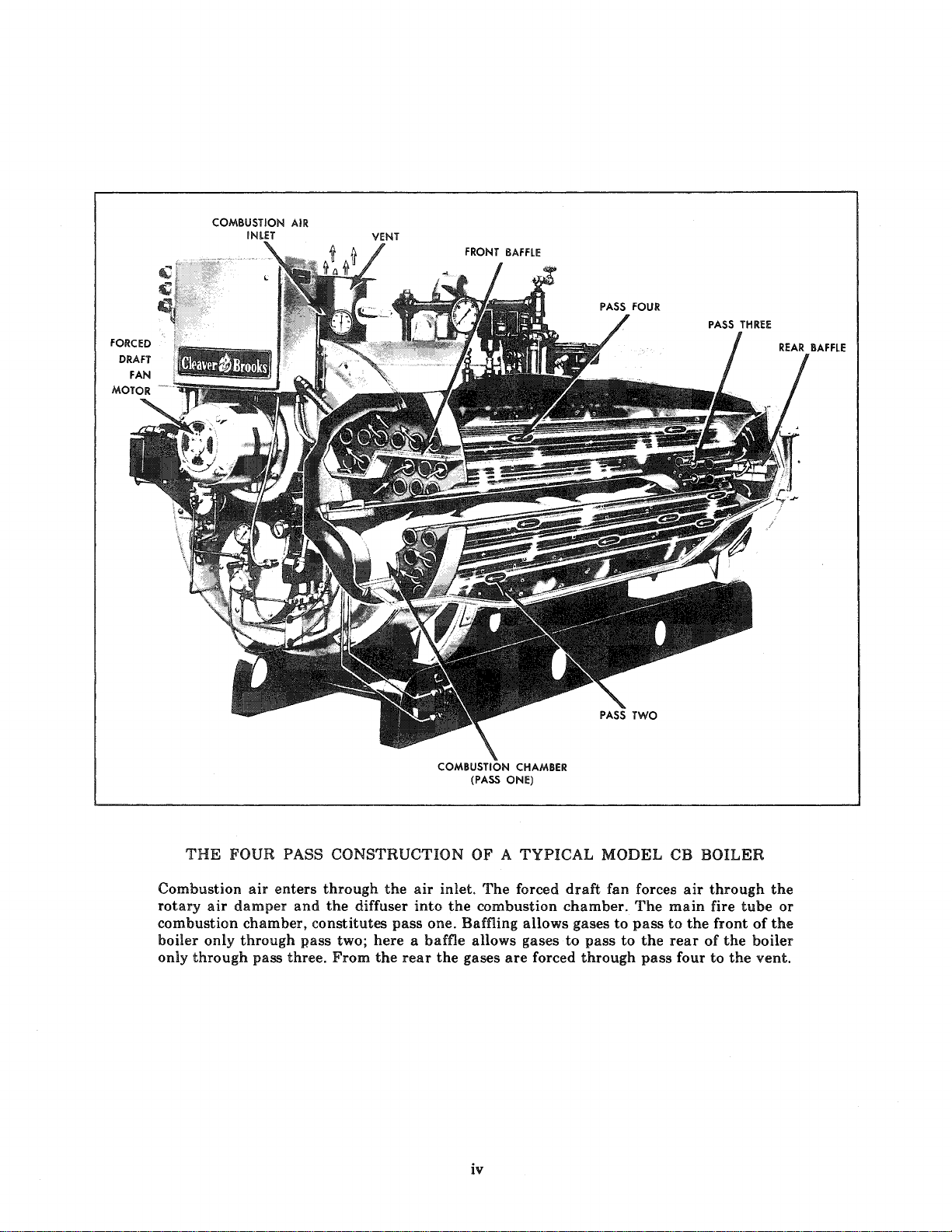
THE
FOUR PASS
Combustion
rotary
air
combustion
boiler
only
only
through
air
enters
damper
chamber,
through
pass
CONSTRUCTION
through
and
the
diffuser
constitutes
P.ass two;
three.
From
the
air
inlet.
into
the
pass
one. Baffling
here a baffle
the
rear
the
OF A
The
forced
combustion
allows
gases
are
iv
TYPICAL
draft
chamber.
allows
gases
to
forced
gases
through
MODEL
fan
to
pass
to
forces
The
pass
the
pass
CB
air
main
to
the
rear
four
BOILER
through
fire
tube
front
of
of
the
boiler
to
the
the
or
the
vent.
Page 9

CHAPTER 1
AND
A.
THE BOILER
The
Cleaver-Brooks
packaged
vessel, oil
draft
ponents.
The
draft
accordance
Vessel Code.
the
boiler.
This
low
capacities
The
others,
the
stallation
codes governing
stallation,
tion
boilers
with
Association Div.
(F.I.A.),
underwriters
steel
or
fan,
air
boiler
pressure
boiler
National
are
is a four
boiler.
manual
rated
and
is
to
should
the
to
be
in
the
optional
Factory
gas
control
The
with
Chapter 2 deals
covers
steam
be in
Board
proper
consulted,
above
requirements.
B. THE BURNER AND
The
type
of
fuel used
series
classification.
Series
Series 200
Series
A
boiler
100
700
equipped
Model
boiler
burner,
damper,
pass
pressure
the
ASME
boilers
or
from 25
related
compliance
of
also
conform
such
authorities
series comply, when
equipment,
of
Mutual
SYSTEM
by
These
Light
Light
Gas
to
GENERAL
PRINCIPLES
A. THE BOILER
B. THE BURNER AND
C.
CONTROL
D. AUTOMATIC IGNITION
IE.
COMBUSTION
f.
OIL
fUEL
G.
GAS
fUEL
"CBH"
consisting
burner
and
horizontal
vessel is
Boiler
with
designed for
hot
water
thru
100
equipment
with
Fire
equipment.
permits
to
Factory
Industrial
(FM)
the
boiler
are:
oil (No. 2)
oil (No. 2)
only
burn
oil
Boiler
of a pressure
controls,
associated
firetube
constructed
and
Pressure
tfiis
portion
high
generation
horsepower.
installation,
the
standards
Underwriters.
to
state
and
Prior
having
obtained
Risk
or
other
jurisdic-
etc. All
equipped
Insurance
Insurers
insuring
CONTROl
determines
only
or
gas
and
gas
includes
DESCRIPTION
AND
COMPONENT
AIR
flOW
flOW
is a
forced
com-
up-
in
of
or
in
by
of
In-
local
to
in-
the
OF
CONTROL
equipment
uses
tor
The
attached
inspection
The
type
annular
pilot
light
combination
ignition
The
operates
fire. An
operates
ner
later
to
butterfly
OPERATION
only
switch is
Model
oil
burner
and
entry
which is
oil fuel
of
standard
on a modulating
and
in
this
Combustion
located
motor.
fuel
energize
properly
tion.
An
of
tor
the
shut
or
The
single
in
the
burner
This
through a linkage
the
electronic
operation
monitors
event
the
excessive
burner
phase
SYSTEM
fUNCTION
for
each
one
type
of
incorporated
CBH
boiler
to
the
front
and
maintenance.
is
of
the
gas
burner
type. A
spark
only
gas-oil
both
fuels.
burner,
at
two
burning
optionally
its
components
manual.
air
is
provided
the
front
is
under
same
motor
valve
proportioned
of
burner
or
oil
valves.
safety
and
in
the
flame
loss
down
steam
control
60
hertz
conjunction
of
pressure
distinct
fuel
at a time,
in
has
head,
the
high
is
gas
burner
ignited. A
is
normally
unit
whether
rates
equipped
firing
are
head.
Combustion
the
regulates
system
by
actuating
Fuel
for
control
to
shut
flame.
under
circuit
(or 50
fuel. Since
a gas/oil selec-
the
combination
the
burner
readily
pressure
of
the
is ignited by a
burner
spark
uses a
firing on oil
- high fire
gas-fired
principle.
described
by a
centrifugal
control
the
connected
input
and
most
efficient
programs
with a flame
the
burner
Other
or
operates
hertz
low
water
safety
water
when
the
burner
units.
assembly
accessible for
atomizing
high
radiant
gas
that
uses
ignited.
gas
pilot
or
gas,
and
low
boiler
The
bur-
in
detail
blower
air
delivery
of
the
damper
flow
of
gas
to
the
gas
switches
air
the
temperatures.
on
that
are
thus
combus-
sequence
detec•
down
controls
conditions
115
volt,
equipped)
A
for
in
1-1
Page 10
Chapter
1-General
Description
and
Principles
of
Operation
alternating
generally
able
The
wired
the
techniques.
The
standard
control,
ture
valve(s
The
through
control
and
timer
at
the
The
gas
valves
spark
firmed.
the
a
safety
The
proving
ance
the
In
plied,
specific
local
with
in
the
tion
chapter
Chapter
C.
The
valves
to
electrical
programming
familiar
trols
stand
outlined
Identify
out.
The
will
equipped
boiler.
Boilers
operated
main
operating
into
burner
major
control
limit
controls,
),
and
sequence
shutdown
in
interlock
that
proper
same
pilot
operation
to
open.
ignited
The
event
of a flame
interlock.
safety
equipment
company
presence
addition
other
requirements
code.
the
burner
burner
of
individual
and
3.
CONTROL
term
and
with
whether
the
in
and
actual
depend
and
having
energizes
control
"control"
controls
current.
power
the
and
electrical
low
conjunction
control
interlocks
of
to
Refer
the
The
on 3 phase
supply
limit
circuitry
protect
system
and
operating
water
motor
devices.
devices
and
starter.
of
burner
is
governed
or
time.
monitors
prior
The
ignition
oil
burner
will
loss
and -depending
requirements-
adequate
the
standard
to
the
to
determine
limit
components
electrical
FUNCTION
components,
controls
control.
the
individual
or
not
outlined
boiler's
the
locate
upon
whether
operation,
manual.
each
furnished
the
optionally
forced
service
voltage.
and
other
provide
against
components
consist
cut-off,
with
This
de-energizes
or
include
may
of
wiring
control
AND
covers
including
or
The
item
type
it
incorrect
pressure
damper
operation
by
the
programmer
the
to
allowing
of
low fire
must
shut
the
as a result
combustion
controls
fuel
pressure.
basic
be
an
insurance
diagram
the
is
sequence
COMPONENT
the
those
operator
functioning
before
using
with
of
fuel for
is a
hot
ordered
draft
fan
motor
at
the
avail-
interlock
safe
included
of a programming
from
the
operating,
other
flame
likewise
burner
required
specific
circuits.
outlined
more
but
monitored
he
and
the
any
water
features
devices
operation
operating
in
the
or
tempera-
motor,
programming
to
flame
of
upon
that
controls
is
covered
not
must
can
procedures
figure
given
which
fuel
start-up
limit
contains
controls
confirm
main
fuel
on
be
con-
down
action
carrier
furnished
The
important
of
or
by
and
air
insur-
prove
sup-
to
meet
controls
func-
in
this
limited
by
the
become
all
con-
under-
call-
boiler
it
steam
may
is
of
a
in
or
in
is
have
control
PROGRAMMING
CONTROL
Automatically
and
shutdown
operating,
cludes,
operation
valve(s)
cludes
shutdown.
The
both
the
a
The
operation,
must
down
internal
which
causes
period.
The
components
sequence
air
flame
oil
event
control
be
caused
causes a safety
control
Master
and
operating
to
start
forced
Flame
tector
gized by a
through
Lockout
failure
or
on
control,
inter-locks
during
short
reset.
should
tempting
Timer:
ching
quence
through
the
burner.
Timer
the
timer
operating
Flame
pilot
lay
in
monitor
of
pilot
components
AND
(Figure
limit,
in a timed
of
the
and
the
purges
detector
and
gas
of
loss
recycles
or
manually
by loss
checking
the
flame
contains
that
text.
relay
program
draft
relay
senses a suitable
the
Switch
to
ignite
loss
of
lock-out
the
cooling
CAUTION.
be
investigated
to
Actuates
contacts
to
all
Position
and
cycle.
Detector:
and
energizes
response
main
proving
1-1)
programs
period
and
blower
damper
prior
portion
flames
of a flame
automatically
following a
reset
of
circuit
lockout
relay
the
are
referred
(1K):
Energized
controls
sequencing
fan
motor
(2K):
Energized
flame
or a flame
loss
lockout
(LS
the
flame.
will
programmer's
period
The
re-start.
cams
in a non-adjustable
program
the
functions
Dial:
the
(Figure
(figure 1-1):
the
to a flame
flame
period. A standardly
not
listed
FLAME
each
starting,
in
conjunction
interlock
and
proper
motor,
to
switch.
):
pilot
is
(oil
ignition
motor.
ignition
of
this
and
provides
signal.
power
following a
flame.
Additionally,
occur
Indicates
stage
Incorporated
effective
in
the
to
hold
following
to
and
switches
and
starter.
when
flame.
it
routes
Trips
or
main
upon
simulating
checking
required
reason
and
corrected
to
open
the
burner's
necessary
reached
1-1)
Monitors
programmer's
signal.
or
gas)
here.
SAFEGUARD
operating,
devices.
sequence,
system, fuel
The
sequence
and
upon
control
protection
during
interruption.
safety
on
every
event
in
during
major
in
the
operating
when
all
are
to
energize
the
flame
When
control
in
the
burner
on a CB-40
the
opening
condition
period.
before
for
any
before
and
close
timed
operation
to
the
position
in
gas
flame
It
continues
after
expiration
equipped
with
This
in-
the
in-
burner
monitors
in
normal
It
shutis
an
start
anything
this
integral
the
limit
closed
the
de-
de-ener-
circuit
event
it
of
flame,
of
can
be
lockout
at-
swit-
se-
operate
of
burner
or
oil
re-
to
A
1-2
Page 11

Chapter
1-General
Description
and
Principles
of
Operation
boiler
detector.
BURNER
manually
A
rectly
starting
FORCED
Directly
bustion
an
oil
fired
motor
by
has a lead
SWITCH
operated
and
stopping
DRAFT
FAN
drives a forced
air.
Also
referred
unit
the
a V
-belt.
BLOWER MOTOR
BLOWER
MOTOR
sulfide
(Figure
start-stop
MOTOR
draft
to
oil
pump
STARTER
(infrared
1-1)
switch
burner
fan
to
as
blower
is
driven
sensitive)
used
operation.
(Figure
provide
motor.
from
for di-
1-1)
com-
On
this
FORCED
(Figure
Energizes
DAMPER
two
A
DRAFT
1-1)
forced
MOTOR
position
motor
through a linkage
fuel
ratio
under
The
spring
The
motor
motor
is
powered
returned
to
actuates
-------mrTIMER
-
---------!!!!-GAS-OIL
FAN
draft
(Figure
that
system,
low fire
the
one
MOTOR
fan
(blower)
positions
to
and
to
the
closed.
or
more
STARTER
1-1)
the
provide
high
fire
open
auxiliary
PROGRAMMING
AND FLAME
SAFEGUARD
CONTR.OL
DIAL
SWITCH
motor.
air
damper
proper
conditions.
position
switches.
air-
and
COMBUSTION
AIR PROVING
SWITCH
DAMPER
MOTOR
AUXILIARY
SWITCH
DAMPER
LINKAGE
BUTTERFLY
GAS
VALVE
----OIL
OIL PRESSURE
PUMP
GAUGE
FIGURE
1-l.
TYPICAL
OIL
AND
GAS
FIRED
MODEL
CBH
BOILER
1-3
Page 12

Chapter
It
also
1-General
operates,
through
valve.
A
modulating
equipment
tion
G for
DAMPER
motor
on a gas
details.
POSITIONING
(Manual-Automatic)
A
three-position
high
fire
through
the
or
switch
low fire
high-low fire
operation.
AUXILIARY
Actuated
SWITCH(S)
by
damper
Description
linkage,
can
be
fired
unit.
(Figure
for
manually
rate
or
motor
and
Principles
the
supplied
(Figure
butterfly
1-2)
as
optional
See
of
Sec-
SWITCH
1-1)
setting
either
establishing a circuit
control
(Figure
shaft
for
automatic
1-1)
rotation.
HIGH-LOW
Each
OPERATING PRESSURE,
HIGH
Operation
gas
PRESSURE.
FIRE
boiler
to
prove
before
has
additional
valves
ped
boiler
per
opening
GAS/OIL
Toggle
either
IGNITION
Provides
of
gas
AND
CONTROLS
MODULATING
(OPTIONAL
GAS FIRING)
has a switch
that
the
ignition
can
switches
for
high
fire
has
an
during
SWITCH
switch
gas
or
used
oil
TRANSFORMER
high
voltage
pilot
or
light
CONTROL
FOR
that
serves
damper
take
place.
that
operation.
additional
the
pre-purge.
(Figure
to
manually
firing.
spark
oil
burner
is
in
An
switch
1-1)
for
control
as a low
a closed
An
oil fired
optionally
to
select
(Figure
ignition
ignition.
fire
switch
position
boiler
oil
solenoid
equip-
prove
circuitry
1-1)
electrode
dam-
for
M lNG
DAMPER
MOTOR
(OPTIONAL
GAS FIRING)
FOR
FIGURE
1-2
TYPICAL
STEAM
CHECK
VALVE
BOILER
AND
GAGE
GLASS
CONTROLS
1-4
Page 13
Chapter
!-General
Description
and
Principles
of
Operation
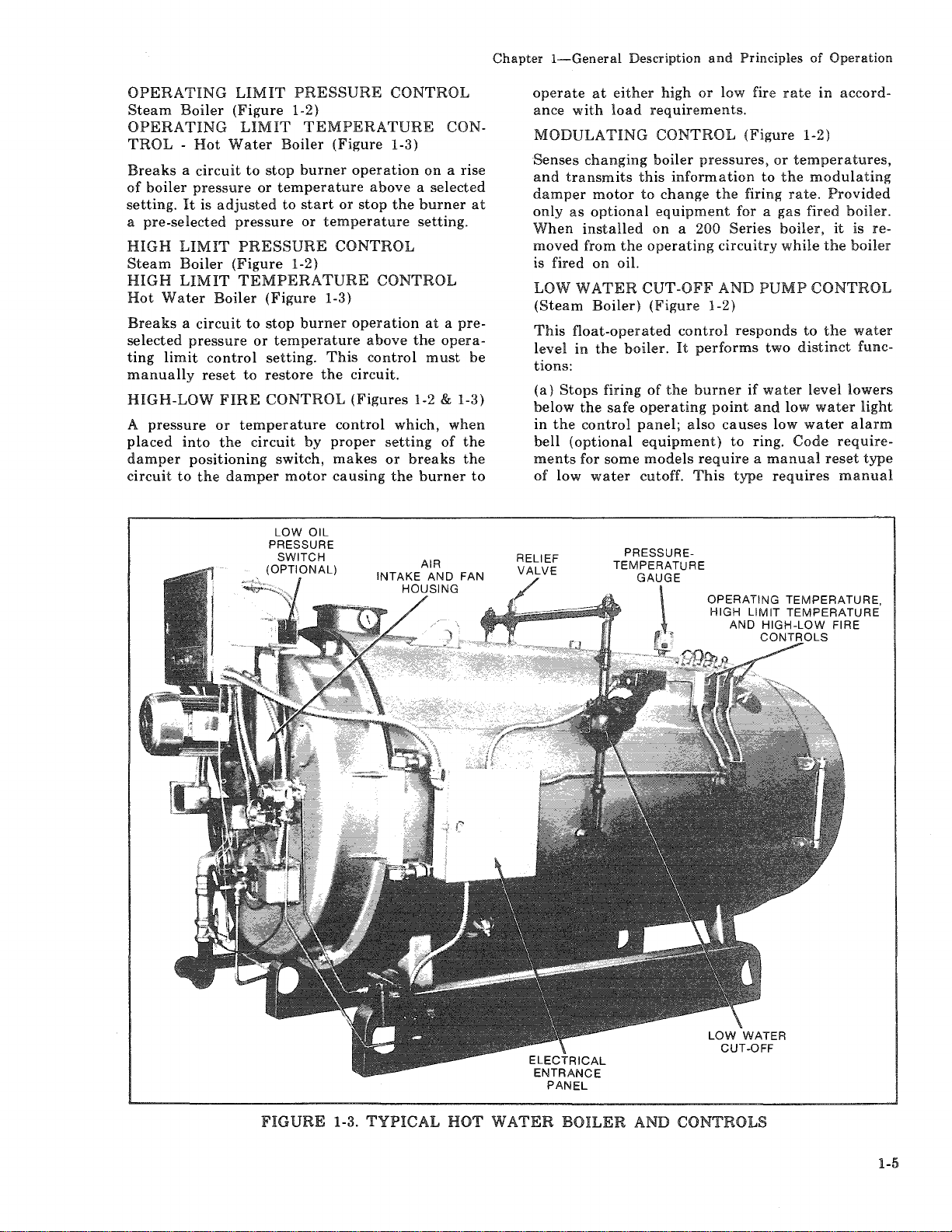
OPERATING
Steam
Boiler
OPERATING
TROL -Hot
Water
Breaks a circuit
of
boiler
pressure
setting.
a
HIGH
Steam
HIGH
Hot
It
is
pre-selected
LIMIT
Boiler
LIMIT
Water
Boiler
adjusted
Breaks a circuit
selected
ting
manually
HIGH-LOW
A
placed
damper
circuit
pressure
limit
pressure
into
positioning
to
control
reset
FIRE
or
the
the
damper
LIMIT
(Figure
LIMIT
to
pressure
PRESSURE
1-2)
TEMPERATURE
Boiler
stop
burner
or
temperature
to
start
or
(Figure
temperature
PRESSURE
(Figure
1-2)
TEMPERATURE
(Figure
to
stop
or
temperature
setting.
to
restore
1-3)
burner
This
the
CONTROL
temperature
circuit
by
switch,
motor
proper
makes
causing
CONTROL
1-3)
operation
above a selected
or
stop
the
CONTROL
CONTROL
operation
above
control
circuit.
(Figures
control
which,
setting
or
the
CON-
on a rise
burner
setting.
at a pre-
the
opera-
must
1-2 & 1-3)
when
of
breaks
burner
at
be
the
the
to
operate
ance
at
with
either
load
MODULATING
Senses
and
damper
only
When
moved
is fired
LOW
(Steam
This
level
changing
transmits
motor
as
optional
installed
from
the
on
oil.
WATER
Boiler)
float-operated
in
the
boiler.
tions:
(a)
Stops
firing
below
the
safe
in
the
control
bell
(optional
ments
for
some
of
low
water
high
or
requirements.
CONTROL
boiler
this
to
pressures,
information
change
equipment
on
a 200
operating
CUT-OFF
(Figure
control
It
performs
of
the
burner
operating
panel;
also
equipment)
models
cutoff.
require a manual
This
low
(Figure
the
firing
for a
Series
circuitry
AND
1-2)
responds
if
point
causes
to
type
fire
or
to
the
gas
boiler,
while
PUMP
two
water
and
low
ring.
requires
rate
rate.
low
Code
in
accord-
1-2)
temperatures,
modulating
Provided
fired
boiler.
it
is re-
the
boiler
CONTROL
to
the
water
distinct
level
water
water
func-
lowers
light
alarm
require-
reset
type
manual
OPERATING
HIGH
LIMIT
AND
HIGH-LOW
CONTROLS
TEMPERATURE,
TEMPERATURE
FIRE
FIGURE
1-3.
TYPICAL
HOT
WATER
BOILER
AND
CONTROLS
1-5
Page 14
Chapter
1-General
Description
and
Principles
of
Operation
resetting
to
down.
(b)
Starts
to
maintain
NOTE;
and
Determine
shipment
operating
AUXILIARY
(Not
shown)
This
float-operated
stop
burner
drops
Manual
manual
a
LOW
(Hot
A
stop
drops
WATER
This
pump
gage
glass
water
WATER
The
the
regularly
piping
below
reset
resetting
low
water
WATER
Water
float
operated
burner
below a safe
COLUMN
assembly
control
glass
provides a means
level.
COLUMN
water
water
column
to
and
start
the
stops
water
LOW
(Optional
operation
the
type
condition.
CUT-OFF
Boiler)
operation
houses
and
shutoff
column
assist
float
bowl
burner
the
at
the
that
and
installation
life.
WATER
control
master
(optional
in
order
(Figure
control
if
operating
(Figure
includes
cocks,
DRAIN
drain
and
in
maintaining
clean
after
feedwater
proper
control
CUTOFF
equipment)
breaks
in
the
event
low
water
equipment)
to
start
1-3)
that
breaks a circuit
water
level
point.
1-2)
the
low
the
and
trycocks.
for
visually
VALVE
valve
is
its
piping
and
free
a low
water
shut-
pump
(if
used)
operating
is
plumb
and
the
boiler
cutoff
level.
throughout
circuit
water
point.
requires
the
burner
in
the
boiler
water
water
cutoff
gage
glass,
The
determining
(Figure
provided
can
be
so
flushed
cross-connecting
of
sediment.
after
to
after
to
and
gage
1-2)
that
A
similar
water
drain
cutoff
valve
is
(optional
furnished
equipment)
pose.
WATER
(Figure
This
TEST
This
filling,
PRESSURE
(Stearn
Indicates
GAGE
1-2)
valve
VALVE
valve
and
Boiler)
boiler's
GLASS
is
provided
(Figure
allows
the
facilitates
GAUGE
(Figures
internal
DRAIN
to
1-2)
boiler
routine
1-1 & 1-2)
TEMPERATURE/PRESSURE
(Hot
Water
compound
A
water
STACK
Indicates
Boiler)
gauge
temperature
THERMOMETER
temperature
(Figure
that
and
of
indicates
water
tional)
SAFETY
safety
A
lieve
signed
purchaser. A relief
boiler
Safety
piping
Code
WARNING:
OR
RELIEF
valve(s)
the
boiler
pressure
for
and
are
the
relief
to
be
of
or
same
installed
requirements.
Only
is
used
pressures
the
valve(s)
purpose.
valves
(Figure
the
VALVE
on a steam
pressure
and
to
valve
with
flush
the
to
be
boiler
pressure.
GAUGE
1-3)
pressure.
(Figure
vented
(Figures
higher
designated
is
used
their
escape
conform
1-7)
manufacturer
auxiliary
for
same
VALVE
gage
vented
inspection.
boiler's
1-2)
flue
gases.
boiler
than
on a hot
to
the
low
pur-
glass.
during
internal
(Op-
1-2 & 1-3)
to
re-
the
de-
by
the
water
and
drain
ASME
or
his
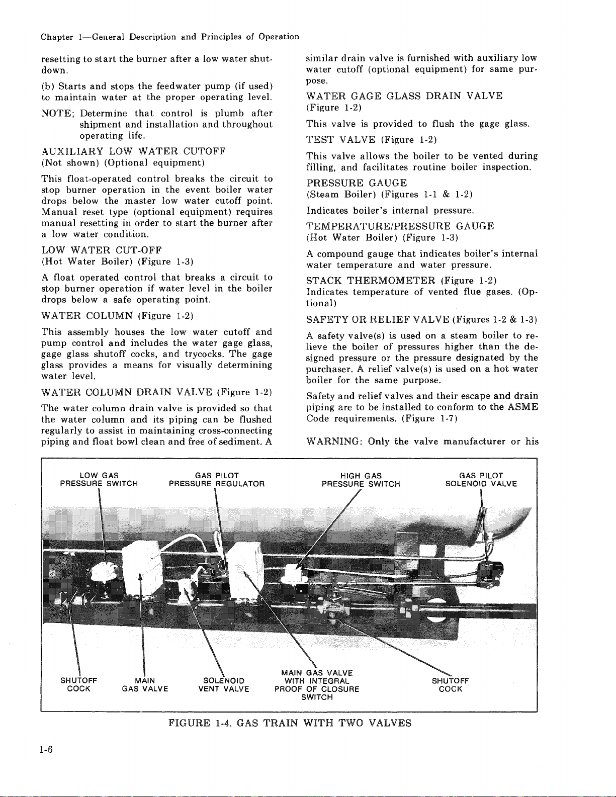
LOW GAS
PRESSURE SWITCH
1-6
GAS PILOT
PRESSURE REGULATOR
FIGURE
1-4.
GAS
PRESSURE SWITCH
MAIN GAS VALVE
WITH INTEGRAL
PROOF OF CLOSURE
SWITCH
TRAIN
WITH
HIGH
TWO
GAS
VALVES
GAS PILOT
SOLENOID
VALVE
Page 15
representative
repair
COMBUSTION
(Figure
A
sure,
sure
OIL
Draws
pressure
an
rotary
nected
OIL
Indicates
1-1)
pressure
whose
of
combustion
PUMP
oil
to
integral
filter.
to
BURNER
sensitive
contacts
(Figure
from
the
adjustable
The
the
the
fuel
zle.
FUEL
Electrically
quence
ner
OIL
to
nozzles.
VALVES
operated
allow
The
these
AIR
PROVING
switch,
close
air
1-1)
supply
burner
nozzles.
pump
blower
motor.
PRESSURE
pump
(Figures
to
oil flow
function
valves.
actuated
to
prove
from
the
tank
and
pressure
is
driven
GAUGE
discharge
open
from
the
of
the
should
adjust
SWITCH
by
air
sufficient
forced
delivers
The
pump
draft
it
contains
regulator
by
a V
-belt
(Figure
pressure
to
1-1 & 1-6)
in a controlled
pump
to
the
valves
is
described
or
prespres-
fan.
under
and
con-
1-1)
noz-
se-
bur-
Chapter
!-General
in
the
FUEL
For
manually
LOW
OIL
(Figure
Switch
below
limit
circuit
for
correct
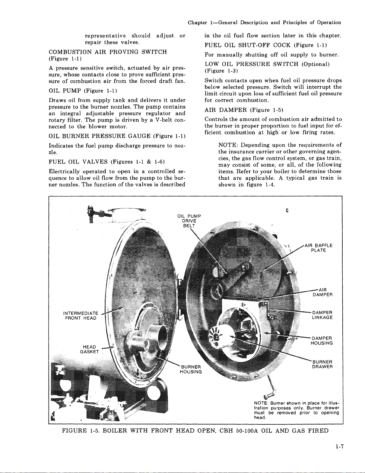
AIR
DAMPER
Controls
the
burner
ficient
NOTE:
the
cies,
may
items.
that
shown
Description and Principles of Operation
oil
fuel flow
OIL
SHUT-OFF
PRESSURE
section
shutting
later
COCK
off
oil
SWITCH
in
(Figure
supply
(Optional)
1-3)
contacts
selected
pressure.
upon
open
loss
when
Switch
of
sufficient
fuel
oil
pressure
will
fuel oil
combustion.
(Figure
the
amount
in
proper
combustion
Depending
insurance
the
gas
consist
Refer
are
applicable. A typical
in
figure 1-4.
flow
of
to
1-5)
of
combustion
proportion
at
high
upon
carrier
control
some,
your
boiler
or
or
to
or
low
the
other
system,
all,
to
air
fuel
firing
requirements
governing
of
determine
this
chapter.
1-1)
to
burner.
interrupt
pressure
admitted
input
rates.
or
gas
the
following
gas
train
drops
the
to
for ef-
of
agen-
train,
those
is
INTERMEDIATE
FRONT
HEAD
HEAD
GASKET
NOTE:
tration
must
head.
Burner
shown
purposes
be removed
AIR BAFFLE
in
only.
Burner
prior
PLATE
place
to
for
illus-
drawer
opening
FIGURE
1-5.
BOILER
WITH
FRONT
HEAD
OPEN,
CBH
50-100A
OIL
AND
GAS
FIRED
1-7
Page 16
Chapter
1-General
Description
and
Principles
of
Operation
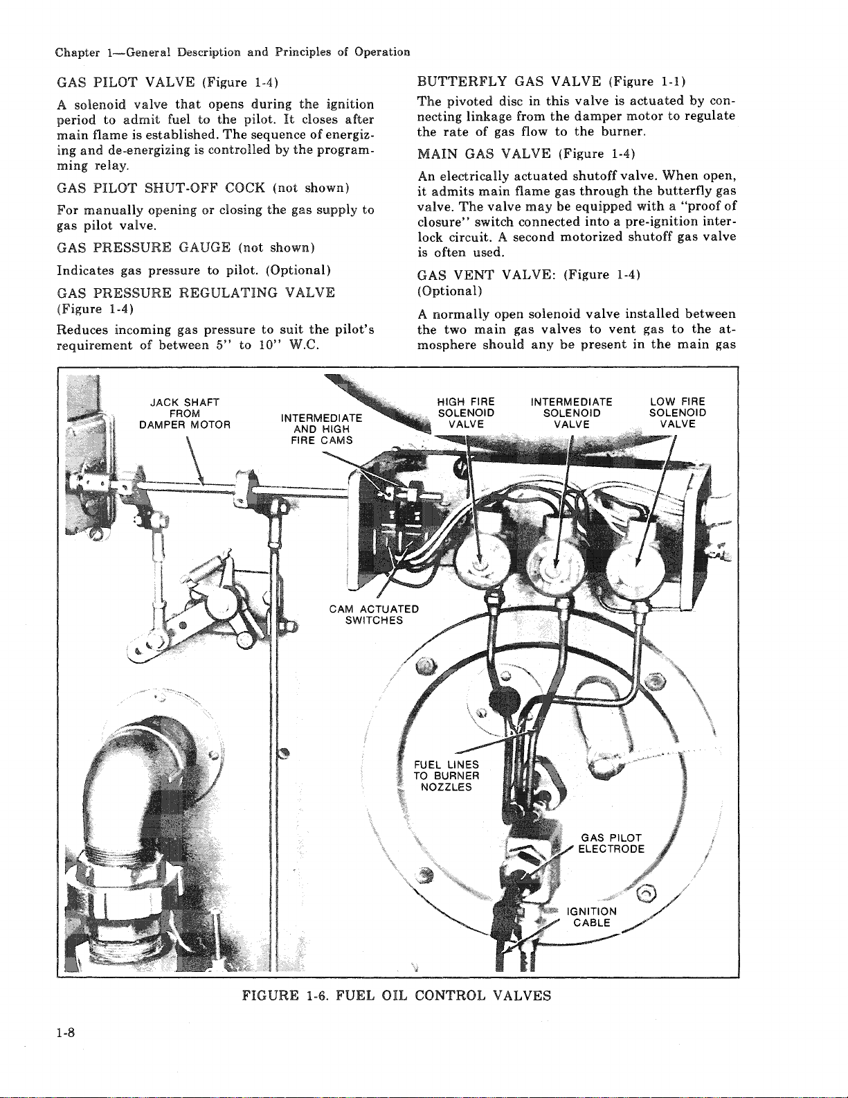
GAS
PILOT
solenoid
A
period
main
ing
ming
GAS
For
gas
GAS
to
flame
and
de-energizing
relay.
PILOT
manually
pilot
valve.
PRESSURE
Indicates
GAS
PRESSURE
(Figure
Reduces
1-4)
incoming
requirement
VALVE
valve
admit
is
established.
SHUT-OFF
opening
gas
pressure
of
between
(Figure
that
opens
fuel
to
the
The
is
controlled
COCK
or
closing
GAUGE
to
(not
pilot.
REGULATING
gas
pressure
5"
1-4)
during
pilot.
sequence
by
(not
the
shown)
(Optional)
to
to
10"
the
It
closes
of
the
shown)
gas
VALVE
suit
the
W.C.
ignition
after
energiz-
program-
supply
pilot's
to
BUTTERFLY
The
pivoted
necting
the
MAIN
An
it
valve.
closure"
lock
is
GAS
linkage
rate
of
GAS
electrically
admits
The
main
valve
switch
circuit. A second
often
used.
VENT
(Optional)
A
normally
the
two
main
mosphere
should
GAS
disc
in
from
gas
flow
VALVE
actuated
flame
may
connected
VALVE:
open
solenoid
gas
any
VALVE
this
the
to
(Figure
shutoff
gas
be
motorized
(Figure
valves
be
(Figure
valve
damper
the
burner.
is
1-l)
actuated
motor
to
1-4)
valve.
When
through
equipped
the
butterfly
with a "proof
into a pre-ignition
shutoff
1-4)
valve
installed
to
vent
gas
present
in
the
by
regulate
gas
between
to
the
main
con-
open,
gas
of
intervalve
at-
gas
1-8
FIGURE
1-6.
FUEL
OIL
CONTROL
VALVES
Page 17
line
when
the
vent
valve
closes
energized.
MAIN
For
gas
pressure
stream
to
GAS
COCK
manually
supply
downstream
regulator. A second
of
the
main
provide a means
whenever a test
mam
gas
valve.
LOW
GAS
PRESSURE
A
pressure
main
pressure.
ting,
the
main
ner
from
gas
the
actuated
line
Should
switch
gas
valve(s)
starting.
with a device
being
tripped.
HIGH
A
main
sure.
switch
main
from
a
GAS
pressure
gas
Should
contacts
gas
starting.
device
PRESSURE
actuated
line
pressure
the
valve(s)
The
that
must
tripped.
LEAKAGE
The
body
that
is
CONNECTION
of
the
used
whenever
conduct a test
closed
valve.
gas
valves
when
(Figure
opening
gas
is
made
switch
pressure
the
contacts
This
that
must
switch
pressure
will
to
switch
be
gas
for
possible
are
de-energized.
the
gas
1-4)
and
closing
of
the
main
shut-off
valve(s),
of
shutting
for
may
off
leakage
SWITCH
that
is
closed
is
above a preselected
pressure
to
switch
drop
will
open a circuit
close,
or
is
be
manually
prevent
usually
SWITCH
that
is
closed
is
below a preselected
rise
above
open a circuit
close,
or
prevent
is
usually
manually
valve
it
is
necessary
reset
has a plugged
leakage
valves
the
main
gas
cock,
be
installed
the
gas
across
(Figure
whenever
below
this
the
equipped
reset
(Figure
whenever
the
setting,
causing
the
equipped
after
opening
or
desirous
across
The
are
fuel
line
down-
line
the
1-4)
set-
causing
bur-
after
1-4)
pres-
the
the
burner
with
being
to
the
Chapter
1-General
On a Model
fire oil
two
electrodes
from
the
the
ignition
and
ignition
gized.
The
ter
low
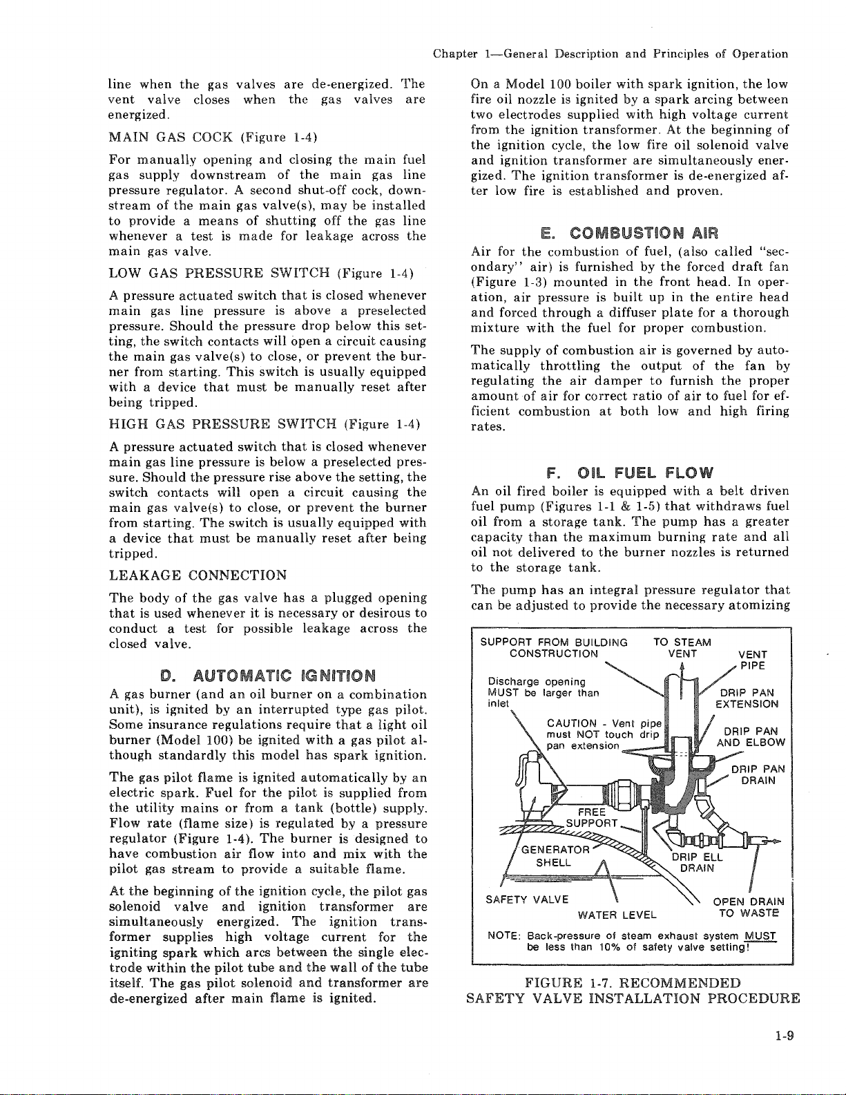
Air
for
ondary"
(Figure
ation,
and
forced
mixture
The
supply
matically
regulating
amount
ficient
Description
100
boiler
nozzle
is
ignited
supplied
ignition
transformer.
cycle,
transformer
ignition
fire is
the
1-3)
air
established
E.
COMBUSTION
combustion
air)
is
furnished
mounted
pressure
through a diffuser
with
the
fuel
of
combustion
throttling
the
air
of
air
for
correct
combustion
the
transformer
is
damper
at
rates.
F.
Oil
An
oil
fired
boiler
fuel
pump
(Figures
oil
from a storage
capacity
oil
to
The
can
SUPPORT FROM BUILDING
than
not
delivered
the
storage
pump
has
be
adjusted
CONSTRUCTION
the
maximum
to
tank.
an
integral
to
is
1-1 & 1-5)
tank.
the
provide
and
Principles
with
spark
by a spark
with
low
fire
are
and
of
fuel,
by
in
the
built
up
for
proper
air
the
output
to
ratio
both
FUEl
equipped
The
burner
pressure
the
TO STEAM
of
Operation
ignition,
high
At
oil
arcing
voltage
the
between
beginning
solenoid
simultaneously
is
de-energized
proven.
AIR
(also
called
the
front
in
plate
forced
the
head.
entire
for a
draft
In
thorough
combustion.
is
governed
furnish
of
air
low
of
and
to
by
the
the
fuel
high
FlOW
with a belt
that
withdraws
pump
burning
has a greater
rate
nozzles
regulator
necessary
VENT
is
returned
atomizing
the
low
current
valve
ener-
af-
"sec-
fan
oper-
head
auto-
fan
by
proper
for ef-
firing
driven
fuel
and
all
that
of
D.
A
gas
burner
unit),
is
ignited
Some
insurance
burner
though
The
electric
the
Flow
regulator
have
pilot
At
solenoid
simultaneously
former
igniting
trode
itself.
de-energized
(Model
standardly
gas
pilot
spark.
utility
rate
combustion
gas
the
beginning
supplies
spark
within
The
mains
(flame
(Figure
stream
valve
gas
AUTOMATIC IGNITION
(and
an
oil
by
regulations
100)
flame
Fuel
or
size)
air
to
of
and
energized.
which
the
pilot
pilot
after
burner
an
interrupted
be
ignited
this
model
is
ignited
for
the
from a tank
is
regulated
1-4
).
The
flow
provide a suitable
the
ignition
ignition
high
voltage
arcs
tube
solenoid
main
flame
on a combination
require
with a gas
has
automatically
pilot
is
(bottle)
burner
into
and
cycle,
transformer
The
ignition
current
between
and
the
wall
and
transformer
is
ignited.
the
type
that a light
spark
supplied
by a pressure
is
designed
mix
the
single
of
gas
pilot.
pilot
ignition.
by
from
supply.
with
flame.
pilot
trans-
for
the
oil
al-
an
to
the
gas
are
the
electube
are
Discharge
MUST
inlet
NOTE:
SAFETY
opening
be
larger than
WATER LEVEL
Back-pressure
be less than 10%
FIGURE
VALVE
of
1-7.
INSTALLATION
steam
of
exhaust
safety
valve
system
setting-!--
RECOMMENDED
PROCEDURE
MUST
1-9
Page 18
Chapter
1-General
HIGH FIRE ORIFICE
VALVE BLOCK
OIL
(HFOV)
Description
and
Principles
OIL SHUTOFF SOLENOID
of
OIL PRESSURE
VALVE
(LFOV-1)
Operation
GAUGE
t
CHECK
VALVE
OIL
TERMINAL
BLOCK
-sUPPLY
__.OIL
OIL
RETURN
FIGURE
MANIFOLD BLOCK
INTERMEDIATE
HIGH FIRE I
OIL VALVE :
(HFOV-1)
HIGH FIRE
VALVE !
OIL
(HFOV-2) )J
HIGH FIRE
OIL NOZZLE
~-
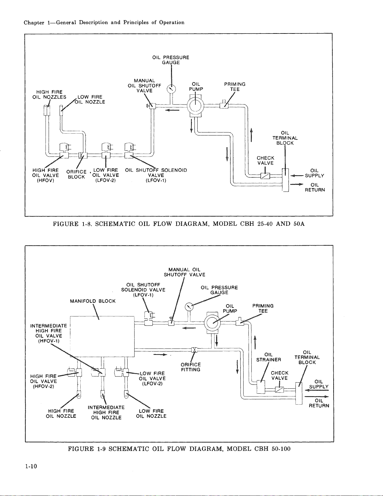
1-8.
SCHEMATIC
---
\----1---L_j------j__J.-----\
OIL FLOW DIAGRAM, MODEL
MANUAL
SHUTOFF
-·
LOW FIRE
OIL NOZZLE
OIL
VALVE
ORIFICE
FITTING
CBH
25-40 AND 50A
t
OIL
STRAINER
OIL
SUPPLY
OIL
RETURN
1-10
FIGURE
1-9
SCHEMATIC
OIL FLOW DIAGRAM,
MODEL
CBH 50-100
Page 19
Chapter
1-General
Description
and
Principles
of
Operation
pressure
read
Oil flow
noid
quence,
(LFOV-1)
energized
ing
fire nozzle.
When
position,
motor,
to
on
the
to
valves.
the
of
these
the
energizes a high
the
oil
the
At
primary,
and
by
the
valves
damper
an
auxiliary
burner
pressure
burner
the
nozzles
proper
the
low
programming
allows
motor
nozzles.
gauge.
time
or
safety,
fire
valve
the
moves
switch
fire
valve.
This
is
controlled
in
the
control.
oil
to
flow
to
actuated
pressure
by
operating
shut-off
(LFOV-2)
The
to
the
the
high
by
is
sole-
se-
valve
are
open-
low
fire
the
Figure
40
and
the
valves
the
high
The
oil
100
size flows
The
intermediate
high
fire
change
ing
the
the
damper
fold
is
I
1-8
shows
50A size
fire
discharge
valve.
from
oil
orificed
the
boilers.
prevents a sudden
valve
from
into a manifold
valve
The
low
to
input
with
opens.
The
to
maintain a constant
valves
The
opens.
the
is
purpose
high
fire
the
increasing
return
used
on
orifice
pressure
pump
on
block
energized
for
this
smoother
line
the
block
the
(Figure
prior
is
flow
from
25
through
between
drop
50
through
to
make
by
balanc-
of
the
pressure.
when
1-9).
to
air
mani-
the
the
as
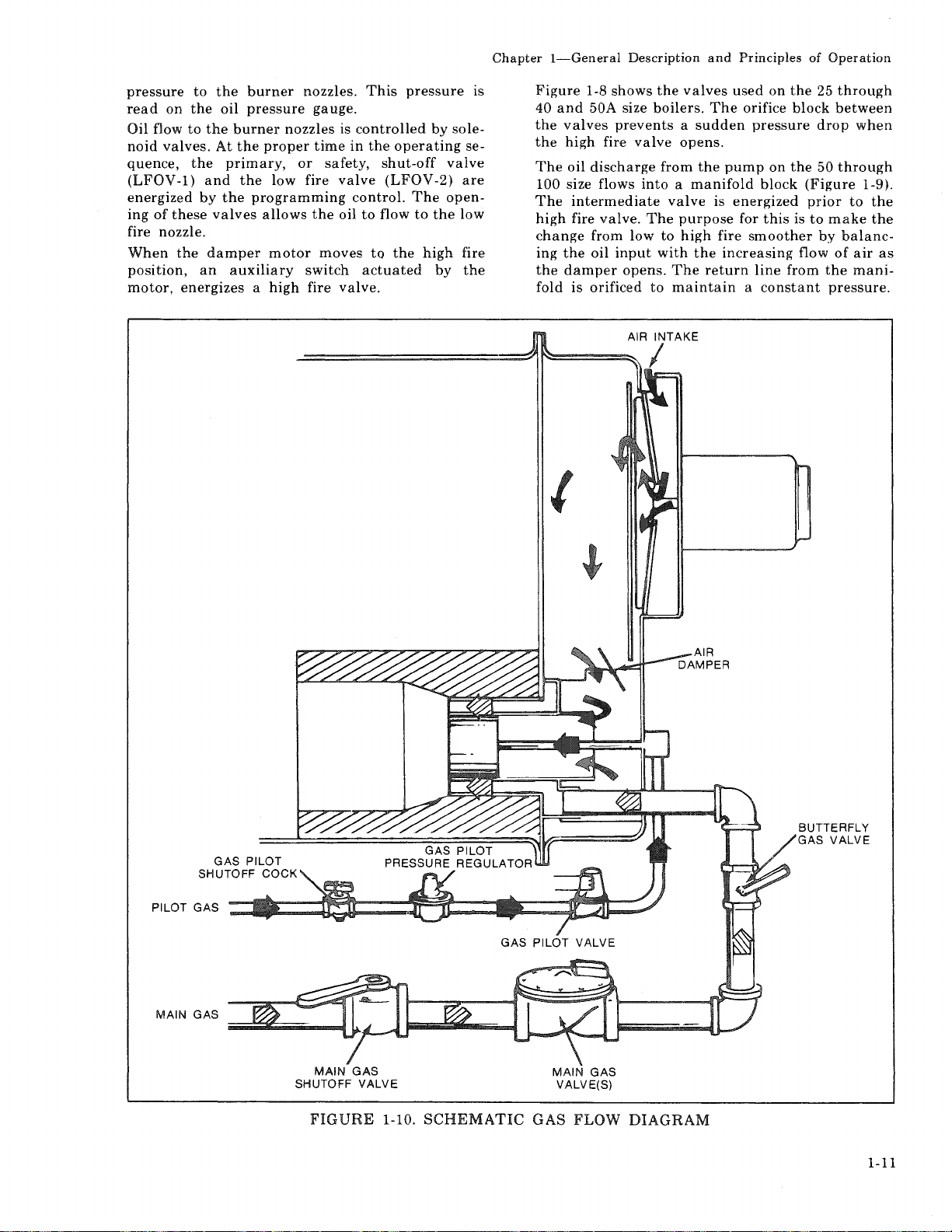
PILOT GAS
MAIN GAS
MAIN
SHUTOFF
FIGURE
GAS
VALVE
1-10.
SCHEMATIC
MAIN
VALVE(S)
GAS
GAS
FLOW
DIAGRAM
1-11
Page 20
Chapter
!-General
Description
and
Principles
of
Operation
G.
GAS
The
gas
flow
system
flow
indicated
Metered
gas
piping
through a pressure
reduced
quirements;
gas
burner.
from
Gas
cock
ating
trols
(opened)
is
ignited
the
time
At
solenoid
programmer
pilot
energizes
allowing
burner.
upon
This
motor
damper,
bustion
to
valve
Gas
this
for
the
into a pressure
pressure
the
mixed
by a controlled
pilot
required
the
beginning
valve
flame
The
the
is
mechanically
and
thus
air.
by
gas from
through a main
the
pressure
through
and
through a butterfly
required
line
prior
pilot
operation
is
established. A solenoid
flow
of
allows
position
with
flame.
for
is
control
is
the
electrically
flow
through
rate
varied
properly
the
combustion
The
energized
proven,
fUEl
is
shown
arrows.
the
utility
regulator
suitable
an
electrically
for
to
the
regulator
the
gas
to
electric
pilot
main
of
the
and
the
the
of
flow
of
the
vane
controlled
in
the
proportioning
flOW
with
(Figure
flows
gas
where
pilot
main
flows
where
gas
and
flow
to
air.
burns
flame
ignition
through
the
pilot
programming
operated
butterfly
to
the
in
the
same
the
direction
1-10)
into
the
burner's
shut-off
the
to
the
operated
gas
valve
operation
gas
shut-off
through a shut-off
the
when
the
pilot
This
spark
only
ignition.
cycle,
circuitry
ignited.
main
valve
burner
butterfly
by
the
maimer
gas
pressure
burner's
to
is
taken
pilot
valve
energized
where
mixture
to
establish
during
the
in
When
control
gas
valve
to
depends
valve.
damper
as
the
and
cock;
main
the
cock.
oper-
con-
the
pilot
the
the
air
com-
of
re-
is
it
is
High-Low
The
firing;
steam
water
damper
either
ance
Modulating
An
modulating
reversible
at
any
Through a linkage
damper
constant
Gas
the
combustion
with
The
unless
to
indicate a sufficient
Some
valves.
mally
for
venting
line
vent
Burner
standard
either
boiler,
boiler,
motor
the
high
with
load
Burner
optionally
damper
and
position
and
air-fuel
flows
through
combustion
main
gas
the
combustion
insurance
Additional
open
vent
gas
when
main
valve
closes
burner
low
or a temperature
makes
causing
fire
requirements.
equipped
will
within
the
zone
valve
requirements
should
gas
Operation
is
equipped
or
high. A
or
breaks
the
or
the
Operation
motor.
move
its
arrangement
butterfly
ratio
throughout
the
burner
where
air
to
produce
cannot
air
supply
requirements
valve
to
any
valves
when
the
pressure
burner
low fire
gas
This
in
either
range.
gas
it
be
proving
specify
be
placed
be
are
main
for
two
control
control
the
circuit
to
rate
fired
boiler
type
of
direction
it
controls
valve
to
maintain
the
firing
orifice
is
present
ring
intimately
main
energized
switch
of
combustion
two
call
for a
between
in
de-energized.
gas
valves
position
on a hot
to
operate
in
accord-
has
motor
or
the
range.
to
enter
mixed
flame.
(opened)
is
closed
main
them
main
open.
on
the
stop
air
air.
gas
nor-
gas
The
a
at
a
is
a
1-12
Page 21
CHAPTER 2
This
chapter
care
of
the
Water
boilers
vice.
dends
and
placing
vital.
remodeled
oil, grease
boiling
lations
The
adequately
less
your
the
Feedwater
for use. See
pumps,
with
A boiler,
proper
operated
or
the
The
chapter
operation.
requirements
are
essential
Constant
in
the
prevention
the
The
waterside
steam
out
is
described
subject
it
is
of
boiler
amount
equipment
and
prevailing
as a part
circulation
as
severe, possibly
pressure
operator
before
A.
is
devoted
pressure
attention
form
of
pressure
or
or
other
the
vessel
of
water
be
covered
prime
performs
of
waterside
that
receivers
codes
intended
vessel.
should
attempting
TH
A.
GENERAl
B. CONSTRUCTION
C. WATER RECWIREMENTS
1.
2.
D. WATER TREATMENT
E.
ClEANING
F.
BOilmOUT
G.
WASHING
H.
BlOWDOWN-STEAM
t PERIODIC INSPECTION
J.
PREPARATION FOR EXTENDED
GENERAl
primarily
vessel.
for
both
to
boiler
to
this
of
longer life, less
costly
hot
importance.
aU valves, piping,
of a hot
damaging,
repairs.
vessel
of
new
water
foreign
to
remove
later
in
supply
in
this
has
an
care
should
are
installed
and
and
the
by
its
designer
familiarize
to
steam
life
and
area
Care
into
initial
boilers
systems
matter. A method
these
this
chapter.
and
treatment
manual.
The
important
it
witl
be checked
practices.
water
system,
system
stresses
himself
to
place
p
HOT
STEAM
the
waterside
and
hot
length
will
pay
down
taken
service is
and
may
accumu-
Neverthe-
type
of
bearing
require.
and
boiler
in
accordance
must
to
avoid
occurring
with
the
unit
ESSU
WATER
water
of ser-
new
contain
cannot
service
ready
requires
shock
BOlliER
BOlliER
OF
A NEW UNIT
OUT
divi-
time,
in
or
of
in
feed
be
to
this
into
E
VESSEL
BOlliER
lAYaUP
B. CONSTRUCTION
All
pressure
with
the
Steam
ceeding 15 psig,
valve
practices,
Pressure
boilers
exceeding 240°F.
but
because
psig
design
Pressure
peratures
pressure
be
as
IV
of
Those
ceeding 15 psig
section I
water
built
to
ASME
boilers
Heating
for
operation
Heating
between
is 60 psig,
high
as
Low
Pressure
steam
Power
boilers
this
vessels
Boiler
for
but
are
of
static
and
constructed
160 psig
boilers
are
Boilers,
for
operation
Code.
Boilers,
may
C. WATER REQUIREMENTS
1.
HOT
WATER
Air Removal
The
hot
water
tends 2 to 3 inches
reduces
trapped
the
Any oxygen
will collect
shell.
the
at
system.
BOilER
outlet
possibility
the
top
or
air
or
be
trapped
are
constructed
and
Pressure
operation
within
constructed
with
be
head
Boiler
240-250°F,
but
because
Heating
designed
constructed
includes a dip
into
of
the
which
the
of
this
water
built
may
to
Code.
and
constructed
of
the
over 250°F
the
boiler.
of
any
shell
is
released
at
the
at
in
accordance
Vessel Code.
pressure
limits
of
good
to
section
Code.
temperature
as
30 psig design,
be
built
section
For
water
minimum
of
static
Boiler
Code.
for
operation
in
accordance
ASME
tube
This
air
which
from
entering
in
top
of
are
not
IV, Low
Hot
up
IV
of
head
to
section
Code.
likewise
which
dip
may
the
the
ex-
safety
water
not
to
160
Low
tem-
design
may
ex-
with
Hot
ex-
tube
be
into
boiler
boiler
2-1
Page 22
Chapter 2-The
The
air
vent
boiler
pression
of
through
the
should
tank.
boiler
this
Minimum
mum
recommended
170
degrees
than
170
are
reduced
water
vapor
corrosion
This
condensation
unit
which
greatly
matter
since
heat
oversized
which
an
from
problem
water
temperatures
Pressure
tapping
be
piped
Any
will
tapping.
Boiler
F.
Water
When
degrees F are
in
temperature
condenses.
occurs
in
operates
for
can
be
efficient
the
can
boiler
combustion
be
minimized
Rapid Replacement
system
prevent
of
or
cannot
that
cannot
water
mal
operation"
This
having
burner
the
When
it
though
The
continuous
help
with
layout
the
cold
water
thermal
stresses. A formula,
be
given,
200
degrees
be
in
a few
stress.
problem
the
so
that
circulating
individual
is
recommended
the
relief
device
circulation
prevent
"cold"
and
controls
possibility
into a hot
but
or
completely
minutes'
This
applies
as
well
can
be
circulating
the
pump
zone
that
heat
users
or
rapid
zone
water.
Contiru.1ous Flow
system
arranged
through
The
trols
boiler
through
stratification
even
A
power
tinuous
operating
Before
operation
should
will
water
rule
of
can
initial
should
that
the
boiler
of
be.
not
the
boiler
within
temperatures
thumb
be
used
flow
rate
conditions.
firing
be
there
under
three
checked
be
by-passed.
of
to
Vessel
on
the
into
the
air
which
find
its
way
Temperature-
boiler
water
used,
The
the
boiler
problem
intermittently
the
actual
controlled
extracts
by
above
of
170
Boiler
should
of
pumping
boiler,
it
should
240
degrees
replaced
time
to
as
during
avoided
pump
burner
is
running.
cannot
circulating
they
be
do
not
by-pass
through
replacement
Through
piped
will
and
be
all
way
valves
to
eliminates
the
unit
to
1/2
to 1 gpm
determine
through
or
refiring
top
center
expansion
is
trapped
out
of
water
temperature
temperatures
the
combustion
to a point
net
result
and
breeching.
is
more
and
load.
by
boiler
all
gases.
However,
maintaining
degrees
Water
be
large
thus
causing
or
"magic
be
borne
water
with
without
causing
periods
initial
in
some
interlocked
operate
pumps
kept
running -even
require
valve
will
the
boiler
of
boiler
the
Boiler -The
the
water
operating
and
make
sure
Constant
the
possibility
and
results m more
the
system.
per
boiler
the
minimum
the
boiler
after
line
of
or
at
the
the
boiler
The
mini-
lower
where
is
severe
which
This
is
design,
the
possible
boiler
F.
-
arranged
quantities
shock,
number"
in
mind
in a boiler
80
degrees
of
"normal-
start-up.
systems
with
unless
are
used,
hot
water.
thus
allow
and
water
controls.
circulation
conditions.
system
that
circulation
horse-
under
boiler
the
com-
top
is
gases
the
that
on
a
is
not
a
this
The
to
ther-
by
the
can
so
con-
the
of
con-
an
has
been
drained,
flow
of
water
Water
The
circulation
boiler
Multiple
boilers
be
through
by
line
plates
psi)
accomplish
If
tional
wide
In
fire''
be
mon
would
portant
Circulation
chart
output
of
taken
use
of
from
are
must
care
is
flow
variations
extreme
position,
loafing.
header
not
in
rate
Boiler
equal
to
insure
the
boilers.
balancing
each
used, a significant
be
this
not
through
cases,
The
be
consideration
stallations.
Pressure Drop
pressure
2.31 ft.
drop
hd.)
Cleaver-Brooks
which
has
more
drop.
Pump
system
outlet
discharge
and
pump.
decreases
impose
It
circulating
pumps
in
Pump
and
desirable
that
culating
location
circulating
connection
to
the
the
expansion
This
air
the
system
is
common
pump,
are
usually
the
boiler
Operation -Pumps
stopped
to
interlock
the
burner
pump
Pressure
The
design
requirements
ted
upon
the
with
air
or
with
Caution
proper
exists
ternal
must
relationship
within
the
surfaces
the
operator
exists
Fig. 2-1
of
boiler
and
system
Installations
or
unequal
adequate
This
cocks
boiler.
taken
across
purpose.
taken
to
the
in
firing
one
and
the
net
result
water
up
to
the
Through
of
less
through
boilers
than a 10
-
pumps
on
system
tank
location
entry
into
head
practice
and
located
room.
by
manual
cannot
is
running.
of
the
will
often
boiler.
Some
an
be
exercised
boiler
are
fully
should
through
shows
the
the
water
temperature
-
size
are
or
can
best
and
gauges
If
balancing
pressure
the
balancing
insure
adequate
boilers,
rates
between
boiler
other
may
boiler
would
temperature
desired
in
point.
multiple
Boiler -There
than
three
all
standardly
operating
degree
It
is
recommended
take
the
boiler
load.
This
on
the
is
preferred
the
system
on
the
to
install a standby
these
adjacent
are
switches.
the
pump
operate
system
dictate
systems
inert
gas,
to
make
of
pressure
so
that
all
wetted
determine
boiler.
maximum
in
relation
drop.
When
used,
care
proportional
be
accomplished
in
the
cocks
drop
or
this
can
the
be
in
the
or
boilers
be
that
to
the
This
boiler
feet
head
equipped
in
any
F.
temperature
suction
suction
and
puts
from
that
the
side
because
and
boiler.
main
circulating
to
the
normally
It
with
the
burner
unless
and
the
the
pressure
are
pressurized
such
as
sure
to
temperature
of
the
boilers'
at
all
times.
that
G.P.M.
to
full
multiple
must
flow
supply
or
orifice
(e.g. 3-5
device
to
propor-
result
in
boilers.
"high
may
the
com-
system
is
an
im-
in-
will
be
( 1 psi-
system
that
the
the
they
boiler
of
the
does
not
system
boilers
started
is
also
so
the
cir-
usage
exer-
nitrogen.
that
the
in-
It
a
a
it
is
2-2
Page 23
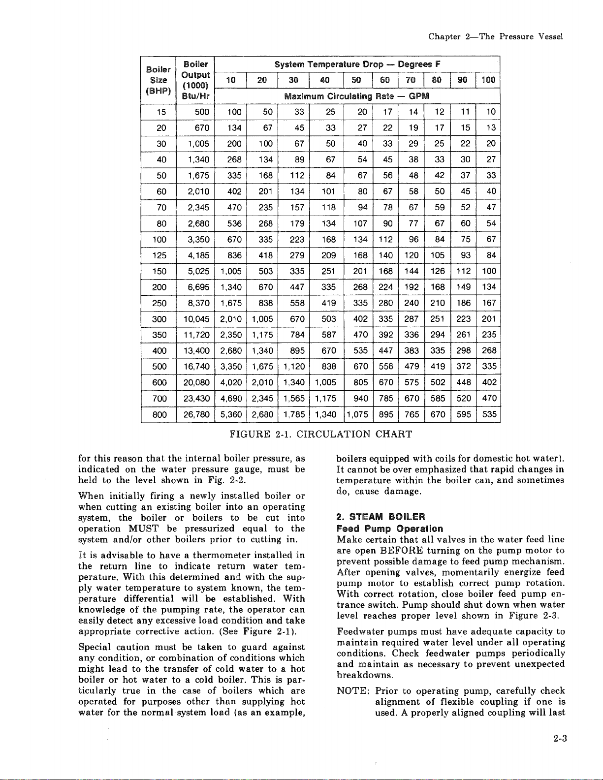
Chapter 2-The
Pressure
Vessel
15
20
30
40
50
60
70
80
Boiler
Output
( 1
()()())
Btu/Hr
500 100 50 33
670
1,005
1,340
1,675
2,010
2,345
2,680
Boiler
Size
(BHP)
100 3,350 670
125 4,185
150 5,025 1,005
200
250
300
350
400
500
600
700
800
6,695 1,340
8,370 1,675
10,045 2,010 1,005
11,720 2,350 1,175 784 587 470 392 336 294
13,400
2,680 1,340
16,740 3,350 1,675 1,120
20,080 4,020 2,010
23,430 4,690 2,345 1,565
26,780 5,360 2,680 1,785 1,340 1,075
System
10
200
134
20
67
100
30
Maximum
45
67
268 134 89
335
402
470
536
168
201
235
268
112 84
134
157 118
179 134
335 223 168
836
418
503
670
279
335
447
838 558
670
895
1,340 1,005
Temperature
40 50
Circulating
25
33
50
67
40
54
67
101
107
134 112
209 168 140
251
201
335 268
419
335
503 402
670 535
838
670 558
805 670
1 '175
940
Drop
- Degrees f'
60
Rate -
20
17
27
22
33
45
56
67
80
94
78
90
168
224 192 168
280 240 210
335
447
785
895 765
70
80
90 100
GPM
14 12
11
19 17 15
25 22
29
38 33
48
58
67
77
96
120 105
144
126
30
42 37
45
50
59
52
67 60
84
75
93
112
149 134
186
251
287
223
261
383 335 298
479
575 502
670
419
585
372
448 402
520
670 595 535
10
13
20
27
33
40
47
54
67
84
100
167
201
235
268
335
470
for
this
reason
indicated
held
to
the
When
when
system,
initially
cutting
the
operation
system
It
the
and/or
is
advisable
return
perature.
ply
water
perature
knowledge
easily
detect
appropriate
Special
any
might
boiler
ticularly
caution
condition,
lead
or
hot
true
operated
water
for
that
on
the
water
level
shown
firing a newly
an
existing
boiler
MUST
be
other
to
have a thermometer
line
to
With
this
temperature
differential
of
the
pumping
any
excessive
corrective
must
or
combination
to
the
transfer
water
in
the
for
purposes
the
normal
the
internal
pressure
in Fig. 2-2.
boiler
or
boilers
pressurized
boilers
indicate
determined
to
system
will
be
rate,
load
action.
be
taken
of
to
a cold boiler.
case
of
other
system
FIGURE
boiler
gauge,
installed
into
to
prior
to
return
and
known,
established.
the
condition
(See
to
guard
of
conditions
cold
water
boilers
than
supplying
load
(as
pressure,
must
boiler
an
operating
be
cut
equal
cutting
installed
water
with
the
the
operator
and
Figure
to a hot
This
which
an
example,
2-1.
CIRCULATION
as
be
or
into
to
the
in.
in
tem-
sup-
tem-
With
can
take
2-1
).
against
which
is
par-
are
hot
CHART
boilers
It
equipped
cannot
be
over
temperature
do,
cause
damage.
2.
STEAM BOILER
Feed Pump
Make
certain
are
open
BEFORE
prevent
After
pump
With
trance
level
Feedwater
maintain
conditions.
and
possible
opening
motor
correct
switch.
reaches
pumps
required
Check
maintain
breakdowns.
NOTE:
Prior
alignment
used. A
with
coils for
emphasized
within
Operation
that
the
all
turning
damage
valves,
to
establish
rotation,
Pump
should
proper
must
water
feedwater
as
necessary
to
operating
of
properly
domestic
that
boiler
can,
valves
to
in
on
feed
the
the
momentarily
correct
close
boiler
shut
level
shown
have
adequate
level
under
pumps
to
prevent
pump,
flexible
coupling
aligned
rapid
and
water
pump
pump
mechanism.
energize
pump
feed
down
in
Figure
all
periodically
carefully
coupling
hot
water).
changes
sometimes
feed
line
motor
feed
rotation.
pump
when
en-
water
2-3.
capacity
operating
unexpected
check
if
one
will
last
in
to
to
is
2-3
Page 24

Chapter 2-The
Pressure
Vessel
14@
130
120
110
100
90
110
ci
..:
,;7'0
~
...
~60
"'
...
"'
..
... 50
40
J()
20
10
r
+-L-t+
8+-
*FOR
TEMPERATURES
CONSULT
SPECIFIC
CLEAVER-BROOKS
RECOMMENDED
MINIMUM
BOILER
PRESSURE
ABOVE
RECOMMENDED
OPERATING
320°
F,
FOR
PRESSURE
SATURATION
TEMPERATURE
140
130
120
110
100
90
81)
~OI,LI~G)1
7'0
60
50
4@
30
20
10
0
~
FIGURE
a long
mechanical
Wat~r
This
boilers
necessary
the
should
as
NOTE:
F~~d~r
type
operating
water
close when
shown
In
to
feeder
valves
be
only
locked
are
boiler
D.
Maximum
of
pressure
with
good engineering
functions
of
+
§!
~
time
0
...
2-2.
g
~
...
PRESSURE -TEMPERATURE
and
provide
operation.
Op~ration
of
operation
at
open
the
discharge
15 psi
water
water
is
usually
steam
supply
valve.
reaches
in Figure 2-3.
the
event
that
water
are
provided
established
open
'Qut
in
the
installed
with
closed
open
it
that
that
position.
is
or
or
these
they
illegal
unsealed
WATER TREATMENT
effectiveness
vessels,
properly
and
at
the
and
treated
long
lowest cost
operating
boiler
!i
~
....
trouble
applicable
or
less.
line
valve
The
water
the
proper
column
installed,
valves
are
sealed
If
these
to
operate
open
trouble-free
consistent
practice
feed
water.
~
INDICATED
free
It
is
only
and
feeder
level
isolation
it
must
are
not
or
valves
the
valves.
life
are
The
~
iii
TEMPERATUitE
to
S!
~
~
~
("F)
CHART
...
FOR
...
HOT
recommendations
reliable
water
followed rigidly
wanted
Objectives
a)
b)
c)
d)
The
requires
ter
selection
the
amount
practices,
solids
of
and
water
Prevention
sludge
transfer
costly
deposits
and
down
Elimination
boiler
water.
Prevention
caustic
embrittlement
Prevention
accomplishment
proper
introduction
of
pre-treatment
water
of
makeup
source,
etc.
g
~
...
WATER
of a water
treating
to
prevent
corrosive gases.
treatment
of
hard
which
can
lead
to
time
and
of
corrosive gases
of
intercrystalline
of
carryover
of
these
feed
water
treatment
of
the
water
its
chemical
water
These
treating
!!1
BOILERS
consultant
company
the
presence
in
scale
processes
needed,
deposits
impair
overheated
repairs.
of
boiler
and
objectives
into
methods
0
0
~
1:;
~
....
or
should
of
general
the
in
rate
the
are:
or
of
metal
supply
soft
heat
and
cracking
metal.
foaming.
generally
before
the
depends
and
boiler.
The
upon
characteristics,
plant
operating
include
a
be
un-
or
or
af-
2-4
Page 25

Chapter 2-The
Pressure
Vessel
A.
High level
off
turns
pressure vessel
height.
B.
Pump turns on when
reaches
approximately
C.
Low
Water
will
shut
Iowen
D.
Fint
visible
FIGURE
2-3.
DETAILS
filtering, softening,
and
pre-heating.
chemical
Because
compound"
advisable
methods.
ployment
analysis
treatment
of
the
variables
can
to
experiment
Sound
should
of
the
be
recommendations
feedwater,
densate.
The
internal
vessel
should
to
determine
accumulations
and/or
water
consultant
should
It
is
recommended
meter
be
to
accurately
admitted
the
water
pitting.
be
consulted
installed
to
the
treatment
or
waterside
be
inspected
the
presence
of
If
these
or
determine
boiler
TYPICAL LOW
-
CUTOFF
CONTROL
AND
/
~~
of
water:
at
this
B.
Distance
Cutoff
off
if
to this
point
BOILER
(STEAM
de-mineralizing,
After-treatment
of
the
considered a "cure-all"
be
augmented
foreign
conditions
feedwater
for
advice
that a properly
in
the
(steam
Feed pump
point.
initially
water
A-B
3/4
inch.
Poir;>t:
water
level
point.
of
gouge
WATER
boiler
involved,
with
homemade
boiler
surfaces
with
of
any
matter,
on
raw
water
the
amount
or
program
Fi
II
to this
level
is
Burner
glass.
LEVEL
BOILER)
water.
no
one
and
by a
water,
of
the
sufficient
contamination,
of
are
detected
treating
corrective
sized
make-up
of
hot
water)
in
maintaining
WATER
PUMP
deaerating
involves
"boiler
nor
is
treating
their
em-
periodic
and
con-
pressure
frequency
corrosion
the
company
action.
water
line
raw
water
to
aid
it
proper
The
does
assumption.
water
should
generally
is
system
mended
Hot
Steam
boiler
These
damage
steam
til
purities.
wasted,
the
lation
occur.
waterside
general
not
feeling
require
The
treating
be followed rigidly.
operate
seldom
water
for
Water
and
may
practiced,
losses
water
and Steam
water
contain
impurities
to
pressure
system
tests
the
show
During
attention
raw
water
of
unwanted
Follow
the
used
the
company.
On a hot
generally
be
drained
ment
compounds
water
necessary
after
companies
and
Pressure Vessel
The
waterside
clean
Such
life
ficient
safety
from
deposits,
of
the
operation
devices,
necessary
of
grease,
if
pressure
and
expensive
time.
The
installation
the
boiler
will
be
and
cleaning
should
be
provided
of
start-up.
Th':!
pressure
or
hot
system.
densate)
have
been
1)
Cleaning
2)
Partial
3)
Conditions
vessel
water
piping
Although
lines
previously
has
or
or
piping.
The
pressure
on a periodic
conditions
vessel
basis.
and
conditions.
exists
that a hot
water
treatment,
recommendations
company
or a water
Even
on
closed
the
systems
need
and a water
make-up
E.
ClEANING
Piping
piping
oil,
must
vessel
systems
grease
be
heating
condensate
elimination
the
period
must
be
given
as
make
materials
advice
of
system,
and
the
treatment.
for
recommendations,
application
the
pressure
sludge
present,
and
but
vessel
functioning
might
will
and
quite
re-work,
and
operating
subjected
the
waterside
to
during
and
the
represent,
the
steam
the
hot
water
cleaned
been
inadequate.
total
old
system
may
prevent
waterside
This
will
serve
as a check
but
though
and
remains
meter
lines.
connected
or
foreign
removed
surfaces.
should
up
or
of
undesirable
that
to
the
so
that
corrosion
your
water
be
condensate
chemical
entire
system
Consult
procedures.
vessel
and
foreign
not
only
interfere
possibly
repairs
conditions
should
of
the
pressure
the
course
steam
and
in
effect, a closed
and
piping
it
is
is
involved.
adequate
should
reveal
against
water
boiler
this
is a false
of a reliable
consultant
these
units
blowdown
to
be
alert
is recom-
to
the
matter.
to
prevent
On
wasted
unim-
treatment
an
accumudoes
not
treating
cleaning
should
water
treat-
cleaning
must
be
kept
material.
shorten
of
control
with
cause
and
the
ef-
un-
down
which
be
considered
vessel
of
initial
return
return
system
possible
lines
(con-
may
that:
cleaning
be
inspected
true
internal
conditions
to
a
is
of
is
or
of
2-5
Page 26

Chapter
2-The
Pressure
Vessel
indicated
Inspection
initial
starting
tervals
periodic
conditions
If
any
unwanted
consultant
contacted
Any
sludge,
flushed
practiced
scheduling
be
revised.
out
will also be
Any
oil
or
should
be
alkaline
NOTE:
Temperature
hydrostatic
operation
ASME
F.
The
internal
may
have
used
in
removed
and
could
boiling
should
familiar
operation.
Your
will
procedure.
or
be
Suggested
follows:
1.
CBH
CBH
CBH
CBH
CBH
CBH
CBH
CBH
CBH
CBH
out
be
water
be
able
is
yet
unselected,
of
assistance.
Tri-sodium
suggested
The
ditions
chemical
See
chart
Boiler
Model
and
Size
25
30
40
50A
50
60
70
80
100
lOOA
by
chemical
should
thereafter.
inspections
and
be
at
The
will
found.
conditions
or
water
for
recommendations.
mud
out.
The
on
steam
or
frequency
The
treating
or
sediment
effectiveness
boilers
need
for
indicated.
grease
removed
detergent
present
promptly
solution.
tests,
should
Boiler
BOil~OUT
surfaces
oil,
grease
or
manufacturing.
since
they
lower
cause
over
procedures
ready
for
firing.
with
the
procedure
consultant
to
recommend a cleaning
In
the
event
the
procedure
for
phosphate
chemicals
quantities
but
per
Normal
will
an
amount
50
gallons
below
Water-
for
Gallons
210
205 230
275
- 295
375
350
550
535
610
-
analysis
made
regular
of
the
three
6, 9
frequency
depend
upon
are
company
found
of
will be verified
of
blowdown
periodic
of
initial
on
the
by a
draining
heating
boil-out
fill
boil-out,
be
as
Code.
OF A NEW
of a newly
other
protective
Such
coatings
the
heat
heating
or
such
following
boiling
boiler
Flooded
235
310
440
420
650
630
715 5085
595
may
The
outlined
water
service is
and
for
cleaning
vary
of
of
of a tube.
begin,
operator
treating
information
out
caustic
according
one
water
water
Water-
Normal
1750
1710
2290
3125 3665
2920
4625
4460 5250
-
boiler
water.
months
or
12
month
of
further
the
internal
observed
water
should
will
have
the
blowdown
may
have
or
wash-
surfaces
with
of
water
or
for
normal
stated
in
UNIT
installed
transfer
under
new
pound
is suggested.
- 2460
boiler
coatings
must
Before
the
burner
must
burner
company
or
boil-out
unavailable
units
soda
are
of
boilers.
to
of
capacity.
Weight
Flooded
1960
1915
2585
3500
5420
5960
4960
after
in-
be
to
be
and
to
an
for
the
be
rate
be
may
is
as
the
con-
each
2.
When
procedure
be
put
troduce
stirring
pletely
and
heat
Use
gloves,
recommended
caustic
material
in
contact
An
over
3.
of
the
point
tapping
4.
Water
must
solution
which
valves.
valves.
Refer
to
stallation
5.
All
valves
system
solution
6.
Fill
pressure
of
tubes
solution
ture
should
7.
The
boiler
at
a low
the
boiling
five
hours.
8.
Allow a small
boiler
carry
9.
Continue
Shut
10.
Let
boiler
using
with
Remove
11.
waterside
pressure
12.
Inspect
boil
13.
After
or
relief
dissolving
is
suggested.
into a suitable
the
dry
at
all
times
dissolved.
in
small
and
amounts
turbulence.
of a suitable
and
protective
when
chemicals.
or
the
concentrated
with
skin
flow
pipe
top
boiler
openings
of
discharge. A relief
is
usually
relief
valves
be
removed
so
that
it
may
carry
Use
care
in
Section J in
instructions.
in
the
piping
must
be
closed
from
getting
vessel
are
covered.
and
then
of
the
water
be
at
ambient
should
rate
sufficient
point.
Do
not
amount
to
create a slight
off
surface
boil
burner
impurities.
and
down.
cool to
caution
that
safety.
hand
hole
surfaces
water
surfaces
stream.
and
out.
closing
openings
valves
fill
chemicals,
Warm
container.
chemical
until
Add
face
the
the
to
prevent
mask,
into
chemical
chemical
garments
handling
Do
not
permit
solution
or
clothing.
should
be
and
used.
and
steam
before
neither
removing
adding
it
will
contaminate
and
Chapter 5 for
leading
to
prevent
into
the
with
clean
Add
fill
to
the
top.
used
in
temperature.
then
be fired
to
hold
Boil
the
water
produce
of
steam
fresh
overflow
overflow
120°F
the
until
or
water
less,
plates
thoroughly
if
not
clean
and
reinstalling
boiler
and
the
following
water
should
Slowly inthe
water
is com-
slowly
excessive
goggles,
is
strongly
or
rubber
mixing
the
to
attached
routed
or
safety
nor
to a
safety
the
the
to
valves
boil-out
grease
re-installing
valve
to
or
from
cleaning
system.
water
until
the
cleaning
The
tempera-
this
initial
intermittently
solution
for
just
at
pressure.
water
to
that
water
clears.
then
is
discharged
and
wash
using a high
repeat
safety
fire
until
water
dry
come
one
safe
valve
these
in-
the
top
fill
at
least
enter
will
drain
the
the
2-6
Page 27

is
heated
dissolved
corrode
The
above
procedure
a
unit
previously
clean,
however,
possibility
boiler
of
from
On a steam
wasted
desirable
densate
treatment
an
corrosion
water
until
impurities.
is
wasted,
of
accumulation
does
treating
On a hot
generally
be
drained
ment
necessary
companies
compounds
A. STEAM
No
later
than 3 months
boiler
into
thereafter
vessel
cooled
covers
spected
should
to
near
removed
for corrosion,
deposits.
B.
HOT
WATER
In
theory, a
been
initially
that
water
treated)
ded
will
require
However,
entrance
leakage
up
or
mation
pressure
If
the
is
tight,
be
sufficient.
If
there
waterside
months
operation
by
conditions
flUSHING
Upon
interior
high
removed
since
of
of
water,
air
may
of
vessel
operator
then
is
should
after
and
completion
should
pressure
by
consultation
to
at
least
180°F
gases
the
metal.
consideration
contaminating
the
system.
system,
tests
the
raw
not
which
may
used
or
the
show
During
attention
water
of
unwanted
occur.
be
omitted
known
must
materials
condensate
the
elimination
the
must
used
Follow
might
as
the
company.
water
after
and
system,
and
the
treatment.
for
recommendations,
application
chemical
entire
Consult
procedure.
G. WASHING OUT
BOlliER
after
initially
operation
as
conditions
be
and
hot
water
cleaned,
no
the
air
lead
sludge,
waterside.
is
absolutely
an
annual
any
initially
periodically
observed
Of
PRESSURE
be
hose.
flushing
with
and
warrant,
drained
ambient
temperature,
internal
pitting,
BOlliER
system
filled
and
with
further
system
and
cleaning
(new
unnoticed
introductions
to
pitting,
sediment,
certain
waterside
doubt
be
inspected
then
placing
thereafter
during
of
inspection,
flushed
your
If
this
out
deposits
may
water
starting
after
waterside
or
and
with
no
make-up
or
of
raw
corrosion
scale,
the
no
inspections.
VESSEl
the
as
require
consultant
to
drive
otherwise
in
the
to
be
internally
be
given
entering
should
period
be
given
makeup
materials
advice
cleaning
system
water
placing
service,
the
being
surfaces
formation
boiler
raw
water
or
treatment.
old)
may
or
undetected
water
etc.,
that
the
inspection
pressure
later
the
boiler
as
INTERIOR
pressure
required
are
immediate
off
any
case
of
to
the
the
be
of
un-
that
con-
to
the
so
that
or
of
your
should
treat-
cleaning
the
and
pressure
properly
handhole
in-
that
has
(and
water
ad-
allow
make-
and
for-
on
the
system
may
vessel
than
into
indicated
vessel
with
not
fully
or
feed-
is
of
a
water
treatment
may
be
necessary
Professional
cleaning
These
the
ment,
fresh
is
inspections
feed
water
the
water
considered
pressure
vessel
consultant
should
and
Boiler
the
and
lowering
include
water
H.
SlOWDOWN
water
concentrated
its
replacement
of
Chapter 2-The
company,
to
advice
required.
will
treatment.
water
conditions,
make-up
in
establishing
washout
or
water
periodic
re-analysis.
blowdown
water
the
concentration
and
resort
is
recommended
indicate
The
required
periods.
treatment
pressure
- STEAM BOILER
is
the
from
with
feedwater
Pressure
in
extreme
to
acid
the
effectiveness
effectiveness
and
the
amount
are
all
factors
frequency
The
company
vessel
removal
the
inspection
of
pressure
so
in
the
boiler
Vessel
cases,
it
cleaning.
if
acid
of
of
treat-
of
to
be
of
future
feedwater
service
some
of
vessel
that
water
a
occurs.
Solids
this
processes
stances
mations.
capable
of
crusting
Solids
of
centrate
treatment
solids
Scale
insulation
which
and
more
metal.
pressure
time
Scale
magnesium
magnesium
precipitated
with
3
tates
as
form
relatively
thicker
mitted
occur
that
The
requires
are
brought
water
is
designed
that
However,
of
their
high
solids
become
the
boiler
on
from
has
a low
not
only
consequently
importantly
This
vessel
and
costly
is
organic
or
"sludge"
sodium
salts
scale,
with
to
accumulate,
and
bring
lowering
the
in
treated
contribute
removing
efficiency, a
will
less
water
heating
is,
therefore,
forming
heat
barrier.
results
can
can
result
metal
repairs.
caused
salts,
silica
salts
in
by
the
materials
in a fluid
and
but
as
pure
steam,
the
solids.
the
sludge
about
overheating
or
use
of
removal
by
the
prior
to
remove
to
none
of
all
substances
be
present
soluble
and
tend
surfaces.
required
harmful
transfer
This
in
lower
higher
cause
in
damage
primarily
and
the
boiler
use
of
to
suspended
the
boiler
the
If
foaming
can
boiler
feedwater
to
use
the
scale
these
are
small
in
in
the
to
crystalize
Internal
scale
value
retards
operating
fuel
consumption,
overheating
tube
causing
by
oil. Any
water
sodium
maintain
form.
dirt
water
remaining
this
concentration
and
cause
of
of
this
water
even
through
unwanted
and
deposit
in
themselves
and
regardless
amount
the
boiler
high
temperature
chemical
to
prevent
and
sludge.
and
acts
heat
efficiency
failures
boiler
calcium
calcium
are
generally
phosphate
these
The
solids
do
not
boils
priming
harmful
the
metal.
concentration
blowdown.
though
external
sub-
for-
of
en-
water.
and
con-
the
as
an
transfer,
but
of
boiler
or
other
down
and
and
along
precipi-
such
readily
off
water
is
per-
will
deposits
as
is
2-7
Page 28

Chapter
TYPES
There
mittent
2-The
OF
are
two
manual
down.
14.
Manual
Manual
operation
or
of
continuous
The
blowdown
or
lowest
lowering
water,
which
part
the
it
also
accumulates
Equipment
valve
and a shut-off
necessary
the
be
to a safe
properly
B.
Continuous
boiler,
piping
but
supported
Continuous
a
surface
diameter
removal
The
on
the
provided
minating
the
other
vessel
A
controlled
tinual -yet
Periodic
to
increase
blow-off
of
surface
top
with
slightly
purpose
impurities
water.
adjustments
and
center
controlled
or
accordance
The
flow
control
provided
.point
C. frr®quenc:y
When
blowdown
solids
removes
water
by
of
discharge.
continuous
is
or
sediment
along
solids.
When
utilized,
dissolved
surface
manual
or
sludge.
In
practice,
are
opened
operating
From
results,
frequent
schedule
the
frequent
lengthy
Pressure
SlOWDOWN
principal
Vessel
types
blowdown
Slowdown
sludge
the
blowdown
blowdown
boiler
tappings
of
the
dissolved
regardless
is
employed.
are
boiler
solids
removes a portion
in
the
lower
generally
consists
valve.
are
not
normally
supplied
point
Slowdown
blowdown
larger)
concentrated
by
of
discharge.
and
is
tapping
free
used
(furnished
and
water.
blow-off opening,
line
of
the
an
internal
below
the
of
skimming
from
orifice
the
valve
surface
is
- flow
are
made
decrease
with
others.
of
the
test
valve
All
Manual
the
amount
analysis.
and
piping
blowdown
primarily
sludge.
The
and
used
continuous
oil from
with a prescribed
or
continuous
blowdown
suspended
the
valve(s)
periodically
solids
of
in
and/or
standpoint
short
blows.
of
blows
This
of
blowdown:
and
continuous
is
necessary
of
whether
located
so
that
in
the
pressure
part
of a quick
These
along
furnished
others.
All
Piping
to
expand.
in
conjunction
is
the
when
pressure
collecting
working
water
sediment,
surface
of
of
used
to
concentrated
to
the
of
piping
must
Slowdown
is
utilized,
to
remove
the
amount
blowdown
is used
in
addition
the
bottom
accordance
chemical
control,
are
preferred
is
particularly
for
at
the
bottom
in
addition
of
the
of
the
vessel.
opening
with
piping
must
on
units
continuous
furnished,
vessel
pipe
level for
the
pressure
allow
valve
setting
blowdown
are
generally
be
to a safe
manual
suspended
blow'down
surface
of
dissolved
is
to
control
blowdown
with
control
economy
inter-
blow-
the
or
not
to
vessel
sludge
the
with
must
be
with
60"
is
and
is
ter-
oil
or
a conwater.
in
of
the
not
the
to
the
an
tests.
and
to
in-
true
when
suspended
With
the
use
of
uniform
is
In
or
densate,
tly
vessel.
proach
blowdown
concentration
maintained.
cases
where
where
there
blowdown
since less
When
or
exceed
to
the
is a
sludge
dissolved
required.
It
is
generally
blown
down
period,
and
operating
and a schedule
treating
A
hot
openings
down
since
need
remains
corresponding
water
meter
recommended
at
but
this
company
water
for
surface
blowdowns
to
is
conditions.
should
boiler
amount
lines.
D.
Manual
Blowdown
generation
water
dilution
tion
feedwater.
Make
proper
clear
point
Most
Slowdown
is
of
steam
input
then
of
the
sure
blow-off piping,
operating
of
obstruction,
of
safe
discharge.
blow-off
lines
most
boiler
generally a quick
and
Two
a slow
slow
opening
opening
used. Valves will
volved
valves
and
are
make
installed
recommendations.
If
a quick
opening
normally
down
opening
valve
are
opened
accomplished
valve.
When
crack
continue
CAUTION:
first
closed
bodies
The
opening
it
slightly
opening
and
as
or
length
Do
pump
water
pipe
of
the
to
fittings.
each
solids
content
frequent
of
the
feedwater
high
percentage
may
be
employed
accumulates
and/or
pre-determined
lower
least
may
these
once in
vary
depending
The
be
recommended
or a water
does
not
blowdown
are
seldom
be
alert
to
system
of
raw
recommended
Procedur®
effective
is
at
the
is also low
water
and
condition
and
that
are
provided
opening
valves
vary
valve
globe
type
or
depending
or
manufacture.
tandem
follow
valve
and
in
combination,
first
and
closed
with
the
second
allow
or
the
slowly.
not
open
the
the
lever
action
hammer
blow
is
apt
should
of
the
water
is high.
short
blows a
pressure
is
exceptionally
vessel
of
return
more
water
pure,
con-
less frequen-
in
the
pressure
suspended
limits,
solids
manual
ap-
concentrations
that a steam
every
blowdown
boiler
eight
upon
amounts
by a
be
hour
water
water
consultant.
normally
and
water
water
for
at a time
lowest
practiced.
water
rate
include
bottom
losses
make-up.
make-up
since feed-
blow-
The
and
when
providing a minimum
with
a low
concentra-
tank
and
waste
valve
the
a globe
globe
down
lines
slow
to
if used,
discharge
is
with
nearest
downstream.
valves
upon
manufacturers'
the
last
with
or
slow
stream
to
warm
opening
valve
break
be
determined
piped
two
valves,
the
may
pressure
If
seatless
type
or
former
blowing
opening
up,
open
the
are
vents
to
boiler
be
in-
slow
valve
then
valve
and
valve
is
A
in
a
is
by
2-8
Page 29

actual
gage
as a guide
not
procedures
viewed
operator
valve
Close
and a fast
the
and
Under
left
the
closed.
water
glass
be
interpreted
by
should
operator.
the
boiler.
then
no
circumstances
open
and
blowdown
I.
Insurance
periodic
authorized
given
and
When
gradually
that
that
normally
again
ture
leak.
baking
heating
desirable
If
request
learn
conditions
side
Be
gaskets
or
operation
Have
dimensions,
pressure
found
Also
previous
Be
inspector
After
out
Remove
surfaces
corrosion
inspection
to
permit
preparation
shutting
avoids
can
cause
be
to
prevent
differentials
Draining
of
surfaces.
to
the
internal
of
from
surfaces.
certain
is
items
available
or
previously
have
inspections.
prepared
including
proper
the
waterside
any
and
and
analysis.
approximately
to
adequate
as a rule
should
the
downstream
as
Slightly
close
prevail.
party
watch
possible.
it
tightly.
the
operator
operation
operating
crack
PERIODIC
regulations
of
inspector.
and
the
damaging
harmful
drained
deposits
dry
an
him
prior
that a supply
available
needed
after
generating
temperature,
available
to
cooling
scale
leakage.
Sufficient
removal
for
inspection.
down,
pressure
until
uneven
that
the
unit
that
Some
out
the
inspection
authorized
whether
to
cleaning
along
to
inspection.
information
and
any
perform
hydrostatic.
and
with a high
or
check
Lowering
1/2"
blow,
the
(slow
Then
should
should
is
the
is
however,
since
If
the
the
glass
opening)
close
the
downstream
a blow-off
completed
INSPECTION
or
local
laws
the
pressure
notice
of
the
boiler
the
load
should
vessel
temperature
stresses.
contraction
can
too
he
of
place
for
any
deposits
for
Vessels
all
pressure
cause
expanded
quickly
may
be
heat,
however,
interior
is
being
inspector,
desires
or
flushing
manhole
with
any
the
on
the
capacity,
time
in
repairs
reference
testing
draining
pressure
from
internal
or
water
often
acceptable
this
water
glass
valve,
and
the
never
cooled
present
of
unit
service,
required
of
analysis
cannot
another
direct
valve
valve
next
valve
leave
and
will
require
vessel by
is
generally
from
service
be
reduced
at a rate
differential
should
is
relieved
and
tempera-
tubes
may
cause
on
may
the
boiler.
made
it
is
well
to
observe
of
and
handhole
other
gaskets
back
boiler
modifications.
the
design,
operating
defects
records
vessel,
water
waterside
or
external
in
the
should
be
the
first
to
valve
be
until
valves
an
not
to
the
the
be
at
the
to
the
water-
into
of
by
the
flush
hose.
Chapter
The
fireside
cleaned
ends,
readily
valves,
the
valves
a
fittings
Be
sure
water)
switches
manhole
pressure
rather
safety
pairs.
Clean
level
water
cocks. Also
Check
leaks,
or
than
factor.
out
controls
gage
all
wear,
repair
J.
surfaces
so
that
metal
and any
checked.
that
steam
feedwater
valves
are
and
the
glass
and
water
as
valves,
to
expansion
shut
off
front
or
vessel
extension
Cleaners
low
water
and
cross
and
check
and
piping.
and
corrosion
required.
clean
PREPARATION FOR EXTENDED
2-The
should
surfaces,
previous
valves,
blow-off
prior
to
rear
doors.
prior
to
cords
are
should
cut-off
connecting
out
clean
steam
and
piping
other
Pressure
also
be
welds,
repairs
system
tanks,
opening
preferably
water
drain
valves,
valves,
and
Adequately
entry.
recommended
piping,
piping.
cocks
and
and
damage.
Vessel
thoroughly
joints,
tube
can
(hot
all
fuel
electrical
handholes,
vent
Flashlights
as
work
the
water
Replace
and
tri-
blowdown
valves
for
Replace
be
a
in
lAY-UP
Many
boilers
for
stand-by
non-use.
-
so
that
allowed
There
Your
pany
upon
Whichever
a
ditions
above
ditions.
Swing
prevent
tubes.
Although
tinue
fuel
problems
boiler
periods,
fireside
point
sulphur
certain
high
be
damage
faces
This
are
water
can
circumstances
periodic
methods
open
to
oils,
during
humidity,
serious
during
condition
used
service
Special
neither
to
during
flow
that
and
surfaces
residue
conditions,
boiler
waterside
deteriorate
two
consultant
recommend
method
recheck
lay-up
boiler
of
pollution
limit
the
care
must
that
sulphur
is
even
cooling.
the
enough
tubes
the
does
for
heating
may
attention
from
methods
or
the
in
the
is
used,
of
fireside
to
for
special
head
warm,
control
permissable
be
can
seasonally
frequent
to
condensation
This
can
form
and
corrosive
to
or
time
that a boiler
not
generally
or
seasonal
have
extended
must
be
nor
fireside
corrosion.
of
storage -wet
feedwater
better
method
particular
common
and
allow
variations
area
at
stack
moist
taken
eat
air
regulations
sulphur
to
cause,
shut
shutdowns,
moisture
an
acid
especially
effect
through
other
metal
given
surfaces
treating
installation.
sense
waterside
or
job-site
end
through
avoid
especially
down.
expose
below
solution.
in
areas
of
the
or
heating
is
out
occur
during
loads
or
periods
depending
of
may
content
corrosion
Dormant
and
of
to
these
are
or
dry.
com-
dictates
con-
from
the
con-
unit
boiler
con-
in
the
the
dew
any
Under
with
acid
will
severely
sur-
service.
nor-
of
to
of
a
2-9
Page 30

Chapter 2-The
mal
firing
operation
operation
proper
especially
flue
At
the
by
removing
bustion
side
Sweep
fireside
ever,
flushing
applying
protect
an
anti-corrosive
To
prevent
trol
Dry
will
freezing
the
boiler
moisture
waterside
deposits,
eliminate
materials
vaporizes
boiler
with a hot
gases
from
start
from
surfaces.
away
surfaces
all
and
some
the
cabinet,
storage
be
out
temperatures
must
would
surfaces
soot, etc.
moisture
such
of
moisture
cleaned
condensation
is
Pressure
operation
falling
lay-up,
any
soot
the
tubes,
Brushing
or
vacuum
may
the
surfaces
form
material
keep
the
generally
of
service for
be
cause
must
by
as
quick
Vessel
since
the
any
condensation.
must
water
boiler,
below
thoroughly
or
other
tube
sheets
will
any
be
flushed
must
be
dried
of
heat.
surfaces
by
to
from
control
employed
some
may
exist.
thoroughly
corrosion.
be
Steps
placing
lime
high
temperature
be
maintained,
to
prevent
the
dew
clean
products
and
generally
accumulation.
with
water,
eliminated
by
blowing
It
is good
coating
prevent
rust.
forming
circuit
energized.
when
time
In
this
dried
because
Both
fireside
cleaned
must
of
be
moisture
(at 2 pounds
However,
point.
the
fireside
of
com-
other
fire-
suffice.
howafter
air
practice
them
with
in
the
con-
the
boiler
or
where
method
all
scale,
taken
absorbing
for 3
of
the
The
or
to
any
and
to
cubic
feet
30
cubic
Fireside
corrosive
tories
should
All
openings
hole
and
water
and
and
vents
reaching
should
Wet
be
storage
stand-by
not
practical.
tures
must
taken
to
definite
that
the
cleaned
treated
the
short
water.
unit
period
suggested
corrosion.
tained
Nitrogen
Fireside
refractory
of
volume)
feet
of
surfaces
material
be
to
handholes
steam
should
fireside
made
is
condition
The
be
protect
or
volume)
may
or
grease
brushed
the
pressure
should
valves
be
closed
surfaces.
and
absorption
generally
or
in
possibility
considered.
metal
surfaces.
recommendations,
pressure
internally
should
by
Internal
at
greater
is
surfaces
should
If
of
time.
the
often
vessel
and
re-filled
deaerated
be
fired
Additional
water
water
than
used
must
be
be
wash
silica
gel
on
trays
be
coated
or
clean
vessel
be
should
to
Periodic
used
for a
cases
where
of
Care
however,
be
drained,
water
to
boil
consultant
pressure
atmospheric
to
pressurize
thoroughly
coated.
(at 5 pounds
inside
with
tar
paint.
and
wash
such
shut
tightly.
be
closed.
prevent
materials
boiler
dry
freezing
must
Variables
it
is
thoroughly
to
overflowing
is
not
the
water
chemicals
to
should
the
cleaned
for
the
vessel.
an
anti-
Refrac-
coated.
as
man-
Feed-
Damper
air
from
inspection
renewed.
held
storage
tempera-
again
be
preclude
suggested
with
available,
for a
may
be
minimize
be
main-
pressure.
vessel.
and
in
is
2-10
Page 31

CHAPTER 3
SEQUENCE
A. GENERAL
B. CIRCUIT AND
C. SEQUENCE
Applicable
With
System
D. SEQUENCE
Applicable
With
System
IE.
FLAME LOSS SEQUENCE CIB-40
A.
GENERAl
This
chapter
the
various
ignition
The
timer
the
operation
to
provide
In
the
schematic
the
boiler,
power
right
nents
are
ply
drawing.
nected
mit
Abbreviations
nents
outlined
nations
diagram.
For
supply
side
(coils,
connected
is
shown
to
the
are
an
diagrams, request Cleaver-Brooks
4095.
The
burner
condition
Boiler
water
pressure
limit
high
below
outlines
controls
cycle, firing
in
the
of
all
an
overall
type
the
grounded
is
shown
of
the
solenoids,
to
it.
as a vertical
All
the
it
through
component
for
listed
in
this
chapter
to
aid
in
explanatory
and
when
the
water
is
up
cut-off
control
temperature
limit
pressure
their
cut-off
the
electrical
through
and
shutdown.
programming
other
controls
operating
wiring
diagram.
The
inductive
switches
to
the
in
Figure
applying
booklet
control
following
to
switch.
(steam
control
setting.
diagram
(common)
as a vertical
All
transformers,
hot
side
line
on
components
or
function
various
also
the
on schematic wiring
system
correct
The
boiler)
(hot
or
temperature
the
control
sequence.
inductive
of
the
contacts
when
electrical
3-3.
employ
text
conditions
level
operating
water
CB-20
CIB-40
Programmers
sequencing
starting
sequences
and
components
provided
side
line
lights, etc.)
the
power
left
side
required.
The
sequences
these
to
the
Bulletin
are
in
closing
or
the
operating
boiler)
control
OF
to
Flame
OF
to
Flame
cycle,
of
on
compo-
sup-
of
are
con-
that
compo-
desig-
wiring
C17-
starting
exist:
the
limit
OF
INTERLOCK
OPERATION -
Standardly
Safe
OPERATION -
Optionally
Safe
of
for
the
the
the
per-
low
and
are
OPERATION
CONTROLS
Oil
or
Gas
Equipped
Guard
Equipped
Guard
C131~20
All
entrance
present
fan
starter.
These
action
system
rectly
lay.
tions
justing
sequences
of
except
relate
Chapters 4 and 5 contain
and
the
B. CIRCUIT AND
The
burner
signed
alternating
The
Hz,
by
Control
terminals
programmer
The
ing
requirement
to
trols
listed
quence:
for 115
programming
however,
1.2.
controls
upon
the
boiler
provided.
below
Burner
Operating
(OLC)
Boilers
and
Control
Oil
or
Gas
Boilers
and
Control
and
switches
at
the
line
terminals
do
not
the
fuel
supply
for
the
interlock
to
the
action
specific
controls.
information
CONTROlS
control
current.
circuit
Ll
the
of
switch
limit
circuit
volt,
single
control
the
timing
power
and
terminals 3 and 4 thru
used
fuel -
applicable
wiring
The
and
L2.
in
the
oil
diagram
controls
referred
(BS)
pressure
is
The
are
closed
of
attempt
system
controls
of
the
programming
operating
on
INTERlOCK
is a
two
phase,
will
also
values
limit
or
must
extended
hot
line
circuit
gas -and
regulatory
to
determine
normally
to
in
or
temperature
the
and
power
the
forced
to
correlate
or
feedwater
setting
wire
system
60
Hz
operate
be
multiplied
to
programmer
is
extended
limit
controls.
vary
the
bodies.
used
following se-
draft
the
that
di-
re-
instruc-
and
ad-
de-
(cycles),
on
50
depend-
specific
Refer
the
con-
are
control
is
to
3-1
Page 32

Chapter
3-Sequence
of
Operation
PROGRAMMING SEQUENCE FOR CB20 PROGRAM RELAY
BAR INDICATES
40 50 60
PREPURGE-----------------
TERMINAL
70
80 90 1 00
IGN.
PILOT
ENERGIZED
11
0
PROGRAMMING SEQUENCE FOR CB40 PROGRAM RELAY
TERMINAL
ENERGIZED 0
High
limit
pressure
(HLC)
Low
water
Low fire switch
Auxiliary
100
Gas-oil
High-low fire
Damper
The
controls
are:
Blower
Combustion
*Not
cut-off (LWCO)
switches (AS-1) (AS-2)
and
200 series
selector switch (GOS) 200
positioning
used
motor
air
used on
FIGURE
SHADED BAR
1 0 20 30 40
PREPURGE----------------~
or
(LFS)
control
in
starter
proving
some
temperature
only
(HLFC)
switch
the
running
interlock
switch
100 series
(DPS)
control
series
interlock
(BMSI)
(CAPS)*
INDICATES
50
FIGURE
only
circuit
3-1.
TERMINAL
60
70
IGN.
PILOT
3-2.
C. SEQUENCE
Applicable
CB-20
system.
This
up
thru
the
action
system
the
action
wiring
this
sequence.
NOTE:
to a standardly
flame
sequence
shutdown.
of
except
of
diagram
The
legend
indicates
stage
cycle.
or
on
safeguard
covers
the
for
the
reached
The
the
ENERGIZED
80 90 1 00
OF
OPERATION -
Oil
or
G~s
equipped
and
burner
No
attempt
fuel
supply
those
programming
supplied
on
the
position
bar-graph
wiring
operation
controls
for
this
the
timer
in
the
shown
diagram,
is
system
that
relay.
of
11
program
made
or
directly
Refer
boiler
in
dial
(Figure
the
timer
burner
in
indicates
0 120
boiler
control
from
start-
to
correlate
feedwater
affect
to
following
and
operating
Figure
with
the
1-3)
the
3-1,
the
3-2
Page 33

sequence
cal
schematic
timing
contacts.
the
since
by
On a combination
be
set
for
With
the
programmer
operating
gramming
PRE-PURGE PERIOD
Dial at Dot
When
the
routed
and
to
4.
the
through
Relay
blower
Programmer
nal
10)
to
driving
tion.
boiler
The
be
timer
the
This
prior
running
completed
rotation.
Continuity
this
circuit
In
the
event
time,
or
if
de-energized.
tion
to
the
of
bulletin
wiring
sequence
The
dial
indication
the
timer
other
components
fuel
the
proper
conditions
sequence
burner
switch
the
1K
is energized.
motor
terminal
energize
damper
allows
to
ignition.
a flow
interlock
within
of
the
interlocks
which
they
allows
any
of
subsequently
The
starting
the
limit
the
to
timer
position
will recycle.
The
blower
wired
into
energized
should
The
combustion
ated
by
prove
the
is
not
normally
Toward
is de-energized
motor.
back
to a dosed
fire
position.
To
assure
prior
to
closed
14.
to
The
returned
of
the
NOTE: A burner
motor
the
circuit
and
to
interrupt
be
de-energized for
air
air
pressure
presence
supplied
the
end
of
to
break
The
return
position
that
the
ignition,
the
complete
timer
will
stop
to
the
low fire
low fire
switch
proving
of
the
spring
system
an
start
various
for
this
diagram
of
the
following
and
is
interrupted
during a normal
unit,
the
fuel.
energized
satisfied,
occurs:
is
turned
controls
starter.
13 is
powered
damper
the
open
of
purging
circuit
10
seconds
listed
the
sequence
these
are
open,
will
and
starter
to
interlock
prove
the
any
switch
from
the
combustion
on
purging
the
circuit
in
and
is in low fire
low fire
switch
interlock
until
the
position
are
closed.
cannot
circuits.
control
that
various
programmer
description
not
to
and
gas/oil
and
with
the
following pro-
"on",
to
Power
is also
(from
motor
which
or
high
air
to
terminal
after
below
not
closed
relay
complete
the
programmer
that
the
circuit
if
reason.
(CAPS)
forced
draft
air.
a 100
series
period,
to
the
motor
the
damper
(LFS)
circuit
damper
and
the
be
made
The
techni-
contains
details
refers
the
timing,
governed
cycle.
switch
all
must
other
power
terminals
routed
termi-
begins
fire posi-
through
12
must
the
start
complete
to
continue.
at
lK
will
its
revolu-
(BMSI)
starter
the
starter
is
actu-
fan
This
switch
boiler.
terminal
the
damper
brings
to
position
must
to
terminal
motor
contacts
if
a
the
to
is
the
of
this
be
is
is
to
13
it
low
be
has
the
Chapter
flame
relay
ter
the
first
flame
relay
the
ignition
stead,
tion
IGNITION PERIOD
at
Spark
ignition
5.
The
terminal
"Pilot
Dial
A.
The
nal
from
terminal
and
oil
present
flame
B.
3
The
valve
bustion
flame
relay
The
within
cycle
is
Gas
Pilot
and
700
ignition
are
air,
is
2K
pilot
a 10
to
happened,
lockout
The
cause
condition
fore
attempting
Dial
at
A.
Spark
Terminal
(LFOV),
gized from
energized
the
and
and
Ignited
transformer
low fire
6,
7.
With
the
detected,
Ignited
Series)
transformer
energized
ignition
established.
is
energized.
flame
second
continue.
the
system
will occur.
for loss
should
to
"Main
Burner"
Ignited
7 is
now
already
this
terminal
at
the
3-Sequence
holds
15
seconds
should
cycle
timer
will
attempt
Ignition"
Oil
Fired
solenoid
which
in
combustion
low fire
flame
Oil
or
and
from
spark
When
must
be
period
If
for
will
of
flame
be
investigated
restart.
Burner
powered.
opened,
end
of
in
for
any
of
pull
in
cannot
complete
to
recycle
Burner
is
energized
valves
this
case
air,
flame
relay
2K
Gas
Fired
the
gas
terminal
and
gas
flam~
is.
established
in
order
any
reason
shut
down
or
any
and
The
will
continue
when
terminal
the
main
of
Operation
reason.
pre-purge,
for
any
reason
be
started.
its
revolu-
or
lockout.
(100
Series)
from
are
energized
is
jumpered
ignition
is
ignited.
is energized.
Burner
pilot
solenoid
5.
With
present
the
detected,
and
proven
for
the
ignition
this
has
and
other
unusual
corrected
main
fuel
to
be
6 is de-
flame
proving
If,
af-
the
In-
termi-
to
spark
When
(200
compilot
flame
not
safety
be-
valve
ener-
period.
B.
Gas
Pilot
Main
gas
solenoid
valves
terminal
After a 10
main
flame,
energizing
pilot
valve.
If
for
any
lit,
relay
2K
to
close.
The
control.
Refer
description
Ignited
valve(s)
7.
Main
second
power
the
The
reason
will
safety
to
of
action.
Burner
(gas fired
(oil fired
flame
trial
is
removed
ignition
gas
pilot
main
drop
out
switch
flame
unit)
unit)
is
ignited.
period
from
transformer
flame
flame
does
causing
will
loss
sequence
or
the
is
energized
for
the
terminal
and
is
extinguished.
not
light
the
fuel
trip
to
low fire
proving
the
or
valve(s)
lockout
section
from
of
5 de-
gas
stay
the
for
3-3
Page 34

Chapter
The
condition
before
With
powered
the
burner
conditions:
With
position,
and
With
motor
high
With
routed
makes
the
On
motor
intermediate
ing
of
ing
On a
motor
butterfly
creasing
Closing
fire
This
stops.
quired
BURNER SHI.HDOWN
Dial
The
temperature
With
the
position
When
following
Relay
energized
flame
tinues
purge
Power
circuit
the
position.
At
opens
3-Sequence
cause
should
attempting
the
main
(from
damper
from low fire
the
damper
the
motor
remains
the
switch
is
powered
fire position.
the
switch
through
or
breaks
load
demands.
an
oil
fired
actuates
the
size
the
motor
the
flame
gas
fired
actuates,
valve
the
of
the
rate.
is
the
Demand
by
load
at
"Post
burner
the
high-low
damper
before
the
operating
sequence
1K
drops
and
relay
to
force
period.
is
removed
to
the
low fire
the
end
of
and
for loss
motor
circuit
of
de-energizes
end
will fire
motor
2K
de-energizes
of
be
to
flame
terminal
positioning
positioning
to
in
in
the
directly
in
the
the
the
circuit
unit,
switches
and
high
the
fire
to
the
unit,
through
to
allow a greater
size
of
motor
of
the
firing
conditions.
Purge"
until
in excess
fire
should
the
operating
occurs:
out.
The
closes.
drops
air
through
The
timer
from
damper
position
the
operating
position
high-low
the
limit
motor.
of
Operation
flame
or
investigated
restart.
established,
10)
transferring
switch
subject
switch
the
damper
·a
closed
"high"
the
fire
to
low fire
the
decreases
burner
of
control
Flame
out.
if
or
position,
and
moves
"auto''
to
the
opening
which
in
solenoid
the
high
the
high
opening
linkage,
flame
starting
boiler
steam
of
demand
return
limit
control
main
is
The
the
begins
terminal
The
it
is
not
cycle,
the
blower
fire
rate.
fuel
blower
any
other
unusual
and
corrected
terminal
and
to
in
motor
low fire position.
to
position,
control
damper
of
the
turn
energize
valves
fire
rate.
fire
valve
of
the
the
flow
to
high
gas
flow
cycle.
continues
pressure
is
properly
to
the
control
is
opened
valve(s)
extinguished
boiler
rotating.
11
breaking
motor
already
terminal 8 circuit
motor.
11
power
releasing
following
the
"low"
is
broken
the
damper
an
open
power
which
motor
damper
increas-
Closing
reduc-
damper
disc
in
of
gas, in-
fire
rate.
to
a low
Timer
as
or
water
generated.
adjusted,
low fire
opens.
is
and
motor
in
a post-
returns
in
con-
that
The
to
or
as
the
the
re-
the
de-
the
to
is
is
timer
stops
The
control
cycling
ature
control
starting
and
drops
the
and
D.
SEQUENCE
Applicable
the
CB-40
system.
The
CB-40
ments
Insurance
Mutual
other
terlock
the
tioned
diagram
follow
This
up
the
system
the
wiring
this
NOTE:
On a
be
With
operating
gramming
of
insurance
Engineering
codes.
circuits
following devices
in
Section
to
this
High
fire
switch
Low
oil
pressure
100
and
Low
gas
pressure
200
and
High
gas
pressure
200
and
sequence
thru
shutdown.
action
action
set
of
except
of
diagram
sequence.
The
dicates
stage
The
the
of
the
bulletin
schematic
timing
contacts.
the
since
by
other
combination
for
the
the
programmer
conditions
sequence
as
it
reaches
is now
when
to close
burner
in
steam
the
again
operating
Oil
to
an
optionally
flame
control
Association
200
700
700
wiring
dial
safeguard
is
This
programmer
requiring
B.
determine
sequence.
(HFS)
switch
series
switch
series
series
covers
No
the
fuel
for
those
the
programming
supplied
legend
on
the
position
reached
bar-graph
diagram,
various
for
wiring
sequence
The
indication
the
timer
components
fuel
proper
used
underwriters
Association
switch
in
following
satisfied,
occurs:
its
readiness
pressure
contacts
goes
cycle.
Of'
OPERATION-
or
Gas
equipped
and
to
(F.LA.)
the
in
addition
Refer
to
the
controls
(IRI)
(LOPS)
only
(LGPS)
only
(HGPS)
only
burner
attempt
the
energized
operation
supply
controls
for
this
timer
of
the
burner
shown
indicates
circuits.
this
control
diagram
of
the
and
is
interrupted
during a normal
unit,
the
fuel.
original
for
subsequent
or
water
of
the
through
program
comply
contains
use
is
system
in
various
description
with
such
and
(FM)
of
some
to
the
boiler
provided
made
or
that
directly
relay.
boiler
dial
(Figure
the
timer
operating
Figure
the
The
that
not
to
and
gas/oil
and
with
the
following pro-
position.
re-
temper-
operating
its
normal
boiler
with
control
require-
as
Factory
the
Factory
and
certain
several
those
from
to
feedwater
Refer
in
following
3-2,
technical
contains
details
programmer
the
switch
in-
or
all
of
men-
wiring
and
to
start-
correlate
affect
to
the
1-3) in-
and
the
cycle.
or
on
sequence
the
refers
to
timing,
governed
cycle.
must
all
other
a
3-4
Page 35

PRE-PURGE
Dial
at Dot
When
routed
and
to
4.
the
the
burner
through
Relay
blower
Programmer
nal
10)
to
energize
driving
tion.
boiler
The
i<:
t • .1ired,
This
prior
timer
made.
the
If
the
allows
will
timer
cycle.
The
running
be
completed
timer
rotation
Continuity
sequence
In
the
time,
event
or
if
of
to
they
de-energized.
cuit
from being
the
sequence,
timer
The
energized
should
The
tuated
prove
Toward
fire
will
position
blower
wired
into
be
combustion
by
the
When
(LOPS)
fuel
so
must
supply
the
is
de-energized
motor.
back
The
to
a closed
position.
Existing
complete
and
the
and
de-energized
air
presence
equipped,
F.I.A.
additional
provided
through
plugged
the
seconds
to
IMPORT
not
lay
When
tender
by
the
into
purging
depending
program
used,
must
the
is
activated
ANT:
the
be
high
PERIOD
switch
the
lK
is
energized.
motor
terminal
the
damper
a flow
to
ignition.
stop
until
proof
of
will
interlock
within
to
energize
the
interlocks
continue.
any
of
subsequently
This
will
energized,
will
the
programmer
motor
circuit
to
interrupt
air
pressure
be
closed
pressure
end
of
the
to
break
return
position
requirements
pre-purge
the
programmer.
use
of a "purge
the
programmer.
period
to
upon
control
If
purge
installed.
fire
to
is
turned
limit
controls
starter.
13 is
powered
damper
to
the
open
of
purging
the
high
high
fire
not
stop
circuit
10
seconds
relay
listed
these
are
open,
prevent
or
de-energize
its
revolution
starter
to
prove
the
for
any
proving
from
the
of
combustion
the
low oil
to
indicate
exists.
purging
the
spring
in
and
time
beyond
be
extended
the
bulletin
the
optional
jumper
switch
provide
"on",
to
Power
motor
or
air
fire
position
but
will
(to
terminal
after
3K.
below
not
relay
the
if
occurring
this
to
will
interlock
that
circuit
reason.
switch
forced
air.
pressure
period,
circuit
the
motor
the
damper
and/or
This
is
extender"
This
by
setting
for
details).
purge
provided
closes,
the
additional
power
terminals
is
also
routed
(from
termi-
which
high
begins
fire posi-
through
switch
is
(HFS)
not
continue
12)
must
the
start
allows
closed
fuel
at
3K
will be
valve
later
circuit.
the
starting
this
into
The
lockout.
(BMSI)
the
starter
if
the
starter
(CAPS)
draft
is ac-
fan
switch
that
sufficient
terminal
to
the
damper
brings
to
low
others
that
require
normally
accomplished
that
device
selected
30, 60
allows
or
(refer
extender
with
the
the
purge
purge
is
the
re-
its
of
the
cir-
is
is
to
13
it
is
120
is
re-
ex-
Chapter
time.
The
programmer
damper
this
3
timer
low fire
To
prior
closed
14.
returned
of
NOTE:
timing
restarts
assure
to
to
The
the
motor
is
position.
that
ignition,
complete
timer
to
the
low fire
The
ignition
any
reason
the
pre-purge.
remains
completed.
and
the
the
will
low fire
switch
revolution
the
damper
system
low fire
an
stop
trial
the
and
interlock
3-Sequence
timer
in
is
high
Upon
motor
is in low fire
switch
until
the
position
are
closed.
cannot
flame
relay
The
timer
lockout
of
stopped
fire
position
completion,
returns
(LFS)
circuit
to
damper
and
the
be
started
pulls
will
complete
at
Operation
and
the
until
the
to
the
position
must
be
terminal
motor
has
contacts
if
for
in
during
its
the
start
position.
IGNITION
Dial
A.
Spark
The
nal
5.
terminal 6 which
nal
7.
present
detected,
B.
Gas
The
valve
tion
flame
relay
The
within
cycle
happened,
lockout
The
condition
fore
Dial
A.
Spark
Terminal
(LFOV),
gized
energized
PERIOD
at
"Pilot
Ignited
ignition
The
low fire
With
combustion
the
low fire
flame
Pilot
ignition
are
air,
pilot
to
transformer
energized
ignition
is
established.
2K
is
energized.
flame
a 10
second
continue.
the
will
cause
for loss
should
attempting
at
"Main
Ignited
7 is
already
from
this
at
and
Ignition"
Oil
Fired
transformer
solenoid
in
this
flame
relay
2K
Ignited
Oil
from
spark
When
must
period
If
for
system
occur.
of
flame
be
investigated
to
restart.
Burru~r"
Burner
now
powered.
opened,
terminal
the
end
of
Burner
is
energized
valve
case
is
air,
ignition
is
ignited.
is
energized.
or
and
terminal
and
gas
flame
be
established
in
order
any
will
shut
or
will
when
the
is
jumpered
Gas
Fired
the
gas
5.
present
is
detected,
for
reason
down
any
and
The
main
continue
terminal
main
from
energized
to
spark
and
When
flame
Burner
pilot
solenoid
With
combus-
the
and
proven
the
ignition
this
has
and
other
unusual
corrected
fuel
to
be
6 is de-
flame
proving
termi-
from
termi-
oil
is
pilot
flame
not
safety
be-
valve
ener-
period.
B.
Gas
Pilot
Main
gas
solenoid
minal
F.I.A.
regulations,
valves
Ignited
valve(s)
valve
(oil fired
7.
Main
with a vent
(gas
flame
or
Burner
fired
unit)
is
ignited.
others,
valve
unit)
is
energized
require
between
or
two
them.
the
low
from
main
As
fire
ter-
gas
the
3-5
Page 36

Chapter
3-Sequence
of
Operation
main
gas
valves
open,
energized
After a
main
energizing
lot
If
lit,
to
control.
description
The
condition
fore
With
powered
the
burner
conditions:
With
position,
and
With
motor
high
With
routed
makes
load
On
motor
intermediate
ing
of
ducing
On a gas
motor
butterfly
creasing
Closing
fire
BURNER SHUTDOWN
Dial
The
temperature
With
the
position
When
following
Relays
valve(s)
the
10 second
flame,
valve.
for
any
relay
close.
Refer
cause
attempting
the
damper
from low fire
the
motor
the
is
fire
the
through
or
demands.
an
oil fired
actuates
the
size
the
motor
the
actuates,
of
rate.
at
"Pos~
burner
the
damper
the
lK,
reason
2K
The
should
(from
damper
the
switch
powered
position.
switch
breaks
valve
the
before
is
are
normally
and
closes.
trial
power
the
The
of
for loss
main
motor
remains
of
flame
fired
the
will fire
high-low
limit
sequence
3K
de-energized
is
ignition
gas
pilot
main
will
drop
safety
to
flame
action.
of
be
to
restart.
flame
terminal
positioning
positioning
circu-it
and
motor
to
in
in
the
directly
in
the
the
unit,
switches
high
the
fire
de-energizes
to
unit,
through
to
allow a greater
size
of
motor
Purge"
in
excess
fire
should
the
control
and
simultaneously
removed
switch
investigated
the
high-low
circuit
the
the
until
operating
occurs:
4K
open
out
flame
position
the
a closed
"high"
the
fire
to
the
decreases
vent
period
transformer
flame
flame
does
causing
will
loss
sequence
or
established,
10)
transferring
switch
subject
switch
damper
position,
and
moves
"auto"
to
the
opening
which
solenoid
the
high
the
low fire
opening
linkage,
flame
steam
of
demand
control
return
limit
circuit
drop
and
closes.
energized
valve
for
the
from
terminal
and
is
extinguished.
not
the
fuel
trip
to
any
other
and
corrected
terminal
and
in
mqtor
or
low fire
to
position,
fire
control
damper
of
in
turn
valves
fire
rate.
high
fire
rate.
of
the
flow
to
high
gas
flow
pressure
is
properly
to
control
is
opened,
out.
The
Flame
is
proving
the
gas
light
or
valve(s)
lockout
section
unusual
power
releasing
to
following
the
"low"
is
broken
position.
the
damper
an
open
power
which
motor
the
damper
energize
increas-
Closing
valves
the
damper
disc
in
of
gas, in-
fire
to
a low
or
water
generated.
adjusted,
the
low fire
opens.
main
is ex-
and
also
of
5 de-
pi-
stay
the
for
be-
11
to
or
as
the
re-
the
rate.
the
fuel
is
is
tinguished
blower
boiler
rotating.
Power
circuit
the
low fire
position.
At
the
opens
timer
The
control
cycling
perature
ting
control
mal
starting
The
CB-20
matically
after a power
safety
pilot,
out
will also
condition
Both
the
pre-ignition
CB-20
the
shutdown
CB-40
condition
The
lockout
ing a
necessary
pressed
The
cause
tion
attempting
A. No
The
pilot
a 10 second
terminals 5 and 6 energized.
by
the
within
7) will
not
be
ately
The
timer
Approximately
is
interrupted,
Master
light
and
flame
motor
in a post-purge
is
to
end
and
stops
and
E.
shutdown
or
controls
control
control
safety
should
pilot
pull-in
this
not
energized.
de-energized
blower
will
relay
and
continues
removed
the
damper
position
of
the
operating
de-energizes
as
it
is
now
when
drops
to close
the
burner
and
flAME
and
CB-40
each
time
failure.
the
main
occur
occurs
will
or
will recycle
situation
will
affecting fuel
switch
shutdown. A short
before
and
operation
for loss
be
investigated
to
restart.
flame.
flame
must
period
of
period,
be
powered
motor
stop
after a short
30
the
lK
is
the
alarm
relay
to
period.
from
terminal
motor.
if
it
the
reaches
in
steam
operating
its
readiness
pressure
the
again
lOSS
programmers
the
operating
Both
will
caused
flame,
during
the
of
after
relay
The
seconds
by
or
if
flame
the
prevent
air
flow
in
(if
it
lockout
or
air
must
be
switch
resumed.
flame
be
ignited
the
2K.
the
fuel
and
ignition
and
the
will
continue
after
lockout
de-energized.
bell
(optional)
2K
drops
force
air
The
11
The
motor
is
not
already
cycle,
terminal 8 circuit
blower
original
for
contacts
goes
cycle.
out.
through
timer
breaking
returns
motor.
position.
subsequent
or
water
of
the
through
SEQUENCE
recycle
control
lockout
failure
by loss
or
flame
pre-purge
start-up
interlocks
an
attempt
is self-correcting).
upon
supervisory
manually
cool
button
or
any
and
corrected
and
ignition
The
flame
If
2K
is
valve
circuit
the
fuel
circuit
pilot
valve
to
period
the
switch
The
following a
to
ignite
of
flame.
simulating
period.
or
ignition
open.
to
any
abnormal
reset
down
can
unusual
proven
cycle
not
energized
valve(s)
is -immedi-
closed. -
operate.
of
operation.
ignition
(LS)
flame
are
energized.
closes
controls.
period
begins-
is
(terminal
will
The
the
begins
the
to
in
that
The
re-
tem-
opera-
its
nor-
auto-
or
the
Lock-
The
correct
The
follow-
be
de-
condi-
before
within
proven
will
The
circuit
trip.
failure
if
is
3-6
Page 37

The
timer
resumes
cator
reaches
and
blower
out
switch
tion
can
be
18.
Pilot
but
If
the
pilot
cuit
is
energized
will
be
extinguished
detecting
drop
circuit
blower
The
seconds
The
are
The
cator
and
out
switch
can
C. Loss
If
a
and/or
tector,
conds
circuit
out
the
is
de-energized
motor
lockout
later
flame
energized.
timer
resumes
reaches
blower
must
be
resumed.
of
flame
outage
the
the
to
de-energize
off fuel flow.
tion.
Approximately
switch
The
are
The
cator
and
out
can
If
out,
manual
ferred
that
the
can
manual
and
easier
or
the
to
viates
sibly
often
will
flame
energized.
timer
resumes
reaches
blower
switch
the
be
resumed.
burner
the
trouble
must
and
to
for
may
not
programmer
be
obtained
and
its
controls
in
the
delays
actual
can
operation
determine
from
eliminate
one
that
Remember
most
part
it
refuses
any
of
to
the
operate.
the
motor
must
resumed.
no
flame
flame
continues
switch
and
failure
the
motor
be
flame.
flame
flame
The
trip
failure
the
motor
be
will
shooting
the
assistance
be
readily
and
this
bulletin.
will
event
be
prevented
the
normaL
overlooking
is
that
this
is
doing
safety
operation.
start
will
be
manually
(Refer
main
flame.
is
proven,
from
terminal
10
will
break
relay
to
will
relay
light
operation.
start
will
be
manually
(Refer
occurs
is no
relay
the
blower
30
to
de-energize
light
operation.
start
will
be
manually
(Refer
not
start,
When
or
dot
position
be
de-energized.
re-set
to
the
main
seconds
within 4 seconds
2K.
The
stop
the
to
run.
trip
lK
will
and
alarm
When
or
dot
position
de-energized.
reset
to
caution
during
longer
2K
fuel
sensed
will
valve
motor
seconds
and
alarm
When
or
dot
position
de-energized.
reset
to
caution
or
upon a safety
section
technical
bulletin
in
pinpointing
apparent.
other
controls
by
studying
the
Knowledge
make
troubleshooting
it
is necessary.
by
systematic
against
stage
at
the
which
Following a routine
an
obvious
relatively
is a
its
Never
safety
job
attempt
simple
device
when
features.
the
dial
the
The
before
caution
fuel
7.
The
later.
main
flow
valve
pilot
The
fuel
of
fuel.
opera-
above.)
approximately
be
de-energized.
bell
(optional)
the
dial
the
The
before
operation
above.)
normal
trip
continues
later
master
by
within
circuit
the
bell
the
operation
the
and
opera-
lockout
relay
(optional)
dial
the
The
before
operation
above.)
in
the
operating
should
be
problems
Familiarity
in
the
system
contents
of
the
of
system
much
Costly
down
checks
normal
sequence
performance
may
condition,
to
correct.
and
for
it
shuts
down
to
circumvent
indi-
timer
lock-
cirflame
flame
to
valve
The
30
indi-
timer
lock-
de-
4 se-
shut
lK.
indi-
timer
lock-
lock-
re-
with
the
time
of
de-
pos-
the
or
Preventive
of
all
components
checking
will
occur
either
pilot
Chapter
maintenance
of
the
relay
under
or
main
3-Sequence
should
to
conditions
flame,
recommended.
AB
AS-I, 2
ALWCO AUXILIARY LOW
AR ALARM RELAY
BM
BMF
BMS
BMSI
BS
CAPS COMBUSTION
CCF-P CONTROL
CCT CONTROL
CR-I
DISC DISCONNECT
DM
DMT
DNS DAY-NIGHT
DPS
FD
FFL
FVL
GOS GAS-OIL
GPV GAS
HFS
HFOV-I, 2
HLC
HLFC
HGPS
IT
LOPS LOW
LDL LOAD
LFOV LOW
LFS
LWCO
LWL
LGPS
MGVAS
MGVV
OLC
OL'S
osov
PT
ALARM
AUXILIARY
BLOWER
BLOWER
BLOWER
BLOWER
BURNER
CONTfWL
DAMPER
DAMPER
DAMPER
FLAME
FLAME
FUEL
HIGH
HIGH
HIGH
HIGH-LOW
HIGH
IGNITION
LOW
LOW
LOW
LOW GAS
MAIN
MAIN
MAIN
OPERATING
OVER
OIL
PURGE
BELL
SWITCH-I,
MOTOR
MOTOR
MOTOR
MOTOR
SWITCH
CIRCUIT
CIRCUIT
RELAY-I
MOTOR
MOTOR
SWITCH
POSITIONING
DETECTOR
FAILURE
VALVE
SWITCH
PILOT
VALVE
FIRE
SWITCH
FIRE
OIL
LIMIT
CONTROL
FIRE
GAS
PRESSURE
TRANSFORMER
OIL
PRESSURE
DEMAND
FIRE
OIL VALVE
FIRE
SWITCH
WATER
WATER
PRESSURE
GAS VALVE MGV
GAS VALVE AUXILIARY
GAS V:ENT VALVE
LIMIT
LOADS
SHUT-OFF
TIMER
FIGURE
MNEMONIC
DESIGNATION
ELECTRICAL
and
scheduled
be
followed.
see
that a safety
of
failure
or
from loss
WATER
FUSES
STARTER
STARTER
AIR
PROVING
FUSE-PRIMARY
TRANSFORMER
TRANSFORMER
LIGHT
LIGHT
VALVE-I, 2
CONTROL
SWITCH
SWITCH
LIGHT
CUT-OFF
LIGHT
SWITCH
CONTROL
VALVE
3-3.
DEVICES
of
of
2
CUT-OFF
INTERLOCK
SWITCH
SWITCH
OF
Operation
inspection
Periodic
lockout
to
ignite
flame
is
SWITCH
3-7
Page 38

Page 39

CHAPTER 4
S
AR
A.
GENERAl
INITIAl START -UP
The
instructions
plete
installation
trical,
completed.
The
with
quickly
mentioned
call-out
1.
Chapter 5 contains
should
wiring
Verify
blown
dropped-out
ters
Check
reset
at
The
proper
perature.
available
entire
Chapter
On a steam
column
test
burner
CAUTION:
fuel,
operator
the
locate
photographs
be reviewed
diagram
supply
fuses
and
the
if
necessary.
the
black
boiler
operating
system
2 for
to
valve
is
burner,
controls
and
open
in
has
water
should
and
in
the
should
of
fuel
or
fusetrons,
overloads
lockout
dot.
should
level
Make
vent
operating.
sure
used.
should
water
boiler,
air
until
Prior
charge
valves
blowdown
I G
A.
GENERAL
START-UP
13.
CONTROL
C.
OIL
BURNER START-UP
(100 and 200 SERIES)
!J.
GAS
{200 and 700 SERIES)
NORMAL
E.
PREPARATION FOR
this
chapter
been
and
vent
have
boiler
The
and
identify
following
and
the
adjustment
prior
also
and
proper
etc.
having
switch
open
displaced
to
on
timer
be
fined
using
that
In a heating
be
filled
requirements.
the
escape
firing
piping
and
discharge
or
(All
made
stack
familiarized
the
paragraphs
to
have
open
Check
manual
the
dial
water
treated
and
test
during
of
make
from
drain
FUElS)
assume
and
that
connections
all
components.
various
contents
procedures
actual
been
voltage.
circuit
reset
reset
programmer
setting
with
water
of
ambient
feedwater
application
vented.
valve
on
filling.
steam
is
certain
safety
piping
valves
PERATI
PREPARATIONS FOR INITIAL
(All
FUELS)
SETTINGS
BURNER START-UP
OPERATION
that
com-
all
elec-
are
himself
To
controls
refer
to
of
Chapter
and
this
firing.
of
noted
is
The
studied.
Check
should
the
for
breakers,
all
star-
features.
and
to
the
tem-
the
Refer
water
Leave
after
the
dis-
or
relief
from
all
piped
be
is
to
to
(ALL
Inspect
the
gas
Check for
momentarily
counterclockwise
Before
all
positioned.
For
spection
completed
that
B.
Inspect
ting.
be
pressure,
safety
water
highest
limits
Inspect
a
proximately
pressure
tweeD
setting.
may
but
boiler
G I
FUELS)
{All
FUELS)
all
damper
fired
operating
valves
safety's
especially
might
CONTROl
the
The
pressure
set
slightly
valve(s).
boiler
desired
of
the
high
pressure
control
operating
The
be 2 or 3 lbs.
must
the
ST
a
safe
point
emission
possibly
damage
linkage
and
burners.
proper
closing
in
sake
piping
present a hazard.
operating
but
10%
should
the
pressure
high
10 lbs.
setting
not
exceed
temperature
of
cause
to
for full
also
of
rotation
the
when
viewed
boiler
feed
the
line
make a final
checking for
or
wiring
SETTINGS
limit
control
above
lower
The
temperature
be
water
temperature
vessel.
limit
control
steam
boiler
above
setting,
limit
on
above
valve
pressure
a low
control
hot
property.
UCTIO
of
discharge
water
or
injury
and
the
butterfly
motor
are
or
control
on a steam
highest
than
set
if
feasible,
the
setting.
to
free
of
blower
starter.
from
pump,
if used,
opened
pre-start-up
any
any
(All
desired
the
control
slightly
for
proper
this
should
the
operating
and
pressure
operating
On a hot
should
so
steam
personnel
movement
gas
valve
motor
Rotation
front
of
or
properly
loose
other
situation
FUElS)
for
proper
boiler
setting
on a hot
above
and
within
setting.
be
or
midway
safety
steam
limit
be 5 to
s
that
cannot
on
boiler.
be
sure
in-
or
in-
set-
should
steam
of
the
the
the
On
set
ap-
limit
be-
valve
boiler
setting
water
10°
or
of
by
is
4-1
Page 40

Chapter
4-Starting
and
Operating
Instructions
above
the
operating
ting.
Inspect
ting
operating
Adjustment
covered
Inspect
float
the
which
in
the
and
high-low
should
limit
procedures
Chapter
low
verify
properly.
In
the
event
the
control
settings
required
tive
Set
burner
trance
devices
are
see
or
contact
damper
switch
switches
C.
not
correct.
your
positioning
"off'
Oil
(100 and 200 Series)
PREPARATION
Verify
place.
(Figure
On a 200 series
switch
pilot
Open
return
pump
may
lines
filled
Manually
the
flow
dicates a steady
proximately).
ter
that
Temporarily
1-1).
to
gas
all
line.
should
be filled by use
and
by
oil
pump
may
a few
suction
flow is
A
line.
established.
vacuum
installed
tightness
served
Chapter
and
5 for
system.
Check
"low".
motor
on
trol
The
allow
that
Turn
will
the
gauge.
will begin
damper
a flow
the
"Oil".
cock.
valves
The
be filled
those
priming
hold
picks
be
verified
If
moments
Continue
(or
compound
in
the
of
the
recorded
further
damper
burner
start
The
will
of
limit
temperature
be
slightly
flame
control
lower
for
than
control.
for
these
5.
water
cut-off. Check for
that
boiler
is
listed
here,
If
additional
local
Cleaver-Brooks
control
equipped
is
with
ascertain
information
Cleaver-Brooks.
but
(supplied
switch
close
by
at
all
other
others).
"low".
BURNER START -UP
FOR
driving
close
boiler,
Close
in
the
line
from
with
of
of
large
or
other
in
the
up
when
pressure
no
pressure
stop
oil
suction
system.
for
information
positioning
switch
and
oil
timer
rotating.
open
air
through
INITIAL
belt
the
set
main
oil
the
fuel.
the
fuel
diamet-er
blower
and
reading
the
this
procedure
pressure
Its
readings
future
pressure
in
for
the
FIRING
for
the
oil
the
gas/oil
gas
cock
suction
storage
Short
pump.
pipe
means.
motor
circulates
the
pressure
of
·shows
on
pump
-vacuum)
line
will
guidance.
on
switch is
to
"on".
will
the
programming
pre-purge
the
fireside
oil
shut-off
and
should
the
control
proper
that
of
set-
set-
the
controls
freedom
functioning
optional
that
their
representa-
Leave
power
pump
en-
is in
valve
selector
and
open
line
and
tank
to
the
suction
Long
lines
suction
should
starter
oil.
until
The
gauge
175 psi (ap-
the
gauge
prime
until
the
the
gauge
reveal
be
the
ob-
Refer
oil
piping
set
The
blower
be
indicated
con-
period
area
of
and
the
is
of
is
oil
be
oil
in-
af-
oil
to
at
pressure
the
pleted.
tion
vessel.
low fire
The
to
continue.
position
low fire switch
Now check for
ignition"
ignition
should
door
flame
The
off
valve
With
proper
Turn
complete
in
the
burner
Review
3 for a
takes
INITIAL
Set
manual
switch
will
In
some
ped
completely
may
several
ignition
successful
burner
On
running
vapors
a few
CAUTION:
legend
transformer
be
visible
sight
glass.
can
be
main
burner
is closed.
evidence
oil
pressure,
burner
its
event
switch
cycle
programmer
switch
the
sequence
complete
place
during a starting
START-UP
damper
position
fuel oil
"on".
After
light
and
instances
in
the
fuel
expelled
be
possible
cycles
does
lighting
and
pilot
an
ignition
to
purge
before stopping. After
moments
The
signed
of
ignition
attempt
that
When
fire
position
boiler
mal
operating
hot
A
system
up
period.
content
prior
As
normal
at
low fire,
"high".
flame
is
water
to
is
for
properly
boiler
water
through
If
of
the
increasing
pressure
turn
Observe
The
damper
after
ignition
appears
is energized. An
when
viewed
If
the
unit
seen.
will
not
of
a good
the
unit
to
"off'.
and
stop.
being
turned
of
operation
description
AND
switch
valve
(Figure
the
pre-purge
operate
lines
at
on
initial
preventing
and
for
the
until
all
lines
not
then
occur, do
attempts
adjustments.
failure
before
burner
fan
the
the
boiler
re-setting
and
to
provide a pre-purge
operation
spark
to
alter
might
circumvent
established
approximately
warmed,
pressure
or
must
have a continuous
the
conditions
system
the
the
and
fuel
input.
or
temperature
damper
burner
motor
this
pre-purge
must
be closed for ac-
spark.
on
When
the
through
has a gas
light
since
spark
(or
is
ready
The
programmer
Reset
locked
off.
of
and
FIRING
to
"low".
1-1).
period
its
low fire
firing,
ignition
replaced
burner
are
filled
without
blower
of
any
ignition
control
prior
and
pilot
the
system
leave
the
30
unless
it
temperature
vessel
permit,
boiler
during
the
must
positioning
as
it
progresses
will
return
the
timer
electric
the
gas
pilot)
to
the
safety
out
prior
given in
the
action
operating
Open
Turn
the
rate.
air
may
until
by
fuel oil.
to
go
with
not
repeat
re-checking
will
unburned
failure
safety
switch.
system is de-
to
establishing
flame.
in
this
feature.
burner
minutes
reaches
sooner.
the
entire
be
is
approached
switch
to
is com-
"pilot
dial,
the
spark
the
rear
pilot,
its
oil
shut-
and
be
fired.
will
switch
to
the
Chapter
that
cycle.
the
burner
burner
be
trap-
it
through
oil.
un-
continue
fuel
wait
period
Do
not
any
way
in
low
or
until
its
nor-
flow
warm-
water
warmed
to
to
high
is
It
If
of
4-2
Page 41

Chapter
4-Starting
and
Operating
Instructions
fire position.
the
high
operate
these
lines
flow
through
cause
the
the
low fire flame.
the
After
analysis
fuel flow
Refer
to
properly
necessary
mum
desired
Refer
to
operating
CAUTION:
D.
There
fire oil lines
the
burner
become filled
the
increased
unit
is
test
should
and/or
adjustment
perform
that
burner
rate
sufficiently long
results.
Section E of
and
shutdown
It
is
off
ol"
GAS
possibly
and
for
several
high
combustion
thoroughly
be
made
air
flow
procedures
this
be
this
advisable
fuel
BURNER STARTsUP
(200 and 700 Series)
PREPARATION
Close
main
On a 200 series boiler,
switch
gested
periods
Check
to
connections
was
see
Verify
new
should
system
unless
Determine
entrance
stalling a gas
to
rates.
Check
"low".
motor
timer
The
allow
pressure
the
completed.
action
Now check for
the
to
"gas".
that
of
extended
the
linkage
insure
Chapter
that
set
at
the
Chapter
the
presence
installation, a representative
be
present
to
supervise
this
that
to
5 for
that
Turn
will
will begin
damper
a flow
vessel.
low fire
The
to
continue.
legend
gas
cock
Although
oil
pump
it
has
and
set
factory
5.
has
already
sufficient
the
gas
pressure
information
damper
burner
start
rotating.
will
open
of
air
The
position
low fire
ignition
"pilot
FOR
and
gas
attached
free
screws
but
and
when
purging
train.
test
positioning
switch
and
for
through
damper
after
spark
ignition"
may
be
air
it
may
be
necessary
cycles
to
assure
with
oiL
Failure
fire nozzles
warmed a combustion
with
regulated
test
and
allowed
chapter
sequences.
to
valves.
INITIAL
open
set
not
belt
firing.
to
movement
are
if
adjustment
availability
gas
is first
been
gas
pressure
This
gauge
on
to
the
programming
the
pre-purge
the
this
switch
appears
promptly
air
to
instruments
as
in
Chapter
adjustment
to
fire
enough
for
normal
check for
Review
FIRING
pilot
gas
the
gas-oil
mandatory,
be
removed
the
butterfly
and
tight.
The
of
of
the
turned
of
the
new
done.
exists
can
be
noted
in
the
pressures
switch
"on".
fireside
motor
pre-purge
must
and
will
gas
The
be
pilot.
in
to
trapped
that
of
oil
may
extinguish
and
required.
5.
To
it
at
maxi-
achieve
firing
tight
shut-
Chapter
cock.
selector
it
is sug-
during
valve
that
all
linkage
is
required
gas. On a
gas
utility
into
the
gas
line
at
the
by
in-
line.
Refer
and
flow
is
set
blower
control
period
area
and
of
the
return
period
closed for
When
the
timer
in
to
to
is
5.
to
to
is
dial,
the
ignition
are
energized.
through
The
shut-off
cates
valve
phragm
that
open
ing
diaphragm
the
shows
when
yellow showing
valve
As
ner
Check
With
gas
switch
the
Review
ter
takes
INITIAL
Set
burner
cates
cock.
present
switch
its
necessary
On
running
vapors
a few
CAUTION:
When
extinguished
Burner
or
downstream
to
spin
and
the
burner.
provided
the
sight
main
burner
cock is closed.
"main
opens
it
since
normal
flag
soon
switch
evidence
valve,
burner
3 for a
place
damper
Main
normal
an
two
burn
down,
close
cause
burner"
when
valve,
is energized.
there
valve
in
the
black
when
opened.
is closed. ·
as
valve
off
to
see
unit
in
the
event
switch
of
the
complete
during a starting
START-UP
positioning
switch
"main
"off'
moments
main
burner",
flame
in
the
and
shutdown
to
"bleed"
ignition
to
purge
before stopping. After
The
signed
of
ignition
attempt
that
flame
promptly
will
normally
after
shutdown
of
for a
longer
immediately
main
of
valve
The
nothing
transformer
The
gas
glass
will
determine
energized.
the
click
The
is no
operation
may
window
the
In
the
on
the
action
and
let
that
the
of
a good
is
ready
programmer
being
sequence
description
"on"
and
should
line.
In
allow
cycle.
failure,
the
burner
before
burner
to
fan
operation
spark
to
might
is
established
continue
the
cut-off
period,
gas
cock.
leakage
main
gas
prevents
and
gas
pilot
pilot
flame
may
be viewed
on
the
rear
door.
not
light
since
the
When
of
gas
be
valve
case
programmer
gas
to
turned
of
AND
slowly
this
programmer
air
resetting
provide a pre-purge
alter
when
the
that
In
the
its
solenoid
valve
will
pressure
the
position
determined
on
top
of
the
is closed
of a motorized
stem
indicates
is
confirmed,
valve
pilot
and
be fired.
locked
off.
operation
of
and
FIRING
switch
Circumvent
due
to
when
the
open
ignite
event,
Several
from
the
the
blower
of
any
ignition
and
control
prior
and
pilot
the
burner
to
to
the
valve.
or
during
turn
burner
Investigate
before
valve
tight
"low".
unless
the
system
observe
burn
If
is
timer
dial
the
case
will
not
available.
by
observing
valve
and
turn
finish
has
closed.
operating
Reset
out
given
the
action
operating
timer
the
there
turn
the
to
run
efforts
line.
will
unburned
failure
safety
system
to
establishing
flame.
in
this
is
shut
for a
gas
remaining
flame
blower
switch
and
re-lighting
tight
closure.
valve
main
gas
indi-
main
gas
of a dia-
indicate
actually
Dur-
of
the
which
yellow
valve,
that
the
the
bur-
its
cycle.
main
the
safety
prior
in
Chap-
that
cycle.
Turn
the
dial
indi-
main
gas
is
air
burner
through
may
be
continue
fuel
wait
switch.
is
de-
period
Do
not
any
way
feature.
that
it
down.
second
continues
motor
"off'
correct
the
seating
Foreign
to
is
4-3
Page 42

Chapter
4-Starting
and
Operating
Instructions
material
renovated
in
cleaning,
strainer.
When
flame
fire
position
boiler
is
properly
mal
operating
A
hot
water
system
up
content
prior
After
ed
to
"high''
valve
the
ondary
the
fire, a
instruments,
lated
cedures
analysis
be
ently
The
regulator
from
vice.
require
ing.
Refer
ing
E.
START-UP
Check
Check
reset
Programmer
water
period.
of
to
increasing
normal
at
low fire,
"high''.
fire
movement
air
damper,
air
unit
is
combustion
as
required.
in
and
allowed
long
main
have a vent
obstructions
Local
discharge
Make
to
Section E of
operating
NORMAl
water
setting
and
may
be
gas
lines
purging
is
established
for
approximately
warmed,
pressure
boiler
If
the
Observe
position.
may
thoroughly
Chapter
to
enough
gas
codes
sure
must
through
conditions
system
pressure
turn
is
it
extinguish
analysis
and
fuel flow
adjustment
fire
at
to
pressure
for
or
piping
that
and
shutdown
OPERATION-All
level
and
of
all
lockout
timer
mechanisms.
dial
present
unless
and
the
and
fuel
or
the
the
In
the
not
is
possible
warmed
Refer
5.
maximum
achieve
regulator
opening
proper
insurance
this
this
operating
should
in
adequate
providing a suitable
leave
unless
or
temperature
have a continuous
vessel
permit,
boiler
input.
temperature
damper
burner
event
properly
that
the
low fire
and
should
and/or
to
the
To
properly
it
is
necessary
desired
which
operation
to
the
outside
piping
chapter
information.
supply.
controls.
be
either
care
the
burner
30
minutes
it
reaches
sooner.
during
positioning
as
coordinated
and
requirements
is
the
the
entire
must
be
is
approach-
it
progresses
the
butterfly
increased
flame.
running
be
made,
air
flow
adjustment
perform
that
rate
and
results.
the
pilot
must
of
of
the
not
obstructed.
for
normal
fUElS
Check
at
the
black
new
or
is
taken
in
low
or
until
its
nor-
flow
warm-
water
warmed
switch
to
gas
with
sec-
After
in
high
with
regu-
pro-
this
burner
suffici-
gas
be
free
the
de-
may
build-
start-
all
dot.
of
On a combination
selector
fuel.
Turn
burner
Allow
warmed
fire.
OPERATING
Normal
tioning
of
With
on a high-low
mands.
The
ating
reached,
a.
b.
c.
d.
NOTE:
SHUTDOWN
When
control
increase,
following
The
guished.
blower
through
At
de-energized.
position
Refer
Unit
switch
the
and
boiler
up
operation
switch
the
high-low fire
the
switch
burner
limit
unless:
Burner
Low
water
level
control.
Current
Pressure
mum
level.
There
such
tripped
or
the
opens
or
sequence
fuel
valve
The
motor
the
the
end
and
to
Chapter
is
ready
should
burner
controls
to
before
set
firing
will
continue
pressure
is
manually
condition
or
fuel
of
combustion
can
as
through
operating·
due
if
the
timer
continues
furnace
of
the
The
stops.
to
fuel
unit
be
switch
to
assure
run
at
allowing
should
at
"auto"
control.
set
at
"auto",
basis
or
supply
be
other
motor
circuit
is
breakers,
interlock
limit
to
pressure
burner
occurs:
de-energized
resumes
during
post
purge
timer
has
3 for
timing
re-start.
(Series
set
for
"on".
to
turned
is
overload,
switch
Observe
proper
low fire
burner
be
with
and
burner
according
operate
temperature
detected
is
interrupted.
air
drops
reasons
devices
pressure
or
water
is
operation
running
the
post
the
returned
sequence.
the
until
to
the
under
to
until
"off'.
for
flame
blown
in
or
turned
and
blower
200)
damper
by
to
purge
to
the
fuel
appropriate
action
functioning.
properly
go
to
high
posi-
the
control
will
operate
the
load
de-
the
oper-
setting
low
water
below
temperature
temperature
flame
mini-
shutdowns
outages,
fusetrons
the
system.
"off',
extin-
and
force
period.
motor
its
original
the
the
of
is
air
is
4-4
Page 43

CHAPTER
5
J s
A..
B. PERIODIC INSPECTION
C. WATER
D. WATER
E. OPERATING
F.
G.
H.
t AIR DAMPER ADJUSTMENT
J.
K. MOTORIZED
l.
M.
N. DOOR
0.
P. FIRESIDE
Q.
N
GENERAl
lEVEl
GAGE
Setting
Pressure
Temperature
Combustion
low
High
Programming
Control
Oil
Burner
Oil
Combustion
GAS
Gas
Gas
Combustion
SWITCH AND CAM ADJUSTMENT
SAFETY
SOlENOID
REFRACTORY
FORCED DRAFT FAN
UJBRICATION
and
Controls
Gas
Gas
Operational
BURNER
Nozzles
Pump
BURNER
Pilot
Pressure and
VAlVES
ClOSING
CONTROlS
GlASS
CONTROlS
Adjusting
- Steam
Controls -Hot
Air
Proving
Pressure
Pressure
Adjustment
Adjustment
Adjustment
VAlVES
ClEANING
Control
GAS
AND
Switch
Switch
lest
Flow
VAlVE
Switch
SEAliNG
I
Boiler
Water
TE
Boiler
CE
While
before
tions
used
further
maximum
to
inspection
ing
bolts
mis-adjustments
stallation.
A well
necessary
each
boiler
shipment
such
as
and
operating
adjustment
operating
placing
the
boiler
should
piping, wiring,
and
setscrews
planned
down
A.
GENERAl
is
tested
from
the
burning
occurred
maintenance
time
characteristics
load
after
efficiency
into
be
made
and
aU
to be
or
for
factory,
conditions
installation
and
initial
service, a
of
all
fastenings
sure
that
during
program
costly
correct
controls, connect-
shipment
repairs,
operation
variable
of
the
may
to
economy.
complete
such
as
no
damage
avoids
promotes
condi-
fuel
require
assure
Prior
nuts,
and
in-
un-
or
safety
and
aids
inspection
should
boiler
daily,
activities.
in
obtaining
Cleaver-Brooks
Even
ical
matic
systematic
matic"
responsibility,
tive
chores,
and
schedule
be
established.
room
log
weekly
though
devices
maintenance.
and
This
economies
the
that
in
operation,
and
features
providing
boiler
code
and
local
with a listing
It
is
recommended
or
record
monthly
provides a valuable
equipment.
boiler
make
periodic
do
but
rather
be
and
and
has
it
automatic
these
maintenance.
not
relieve
free
him
time
maintained,
yearly
length
electrical
him
to
inspectors.
of
guide
of
or
devices
the
operator
of
certain
devote
An
procedures
that
recording
maintenance
and
aids
service from
and
mechan-
semi-auto-
require
Any
"auto-
from
repeti-
to
upkeep
5-l
a
Page 44

Chapter
Good
appearing
authorized
operate,
equipment.
all
operation
Alertness
proper
operator
mitting
extensive
steam,
soon
well
tive
checking
screws,
The
this
efficiency
changes.
time
burner. A combustion
adjust
and
5-Adjustment
housekeeping
personnel
adjust
The
material
of
in
gauge
aware
prompt
repairs
water
as
they
as
hazardous.
maintenance
the
packing
air-fuel
will
alert
which
Variations
to
another
fuel
input
economy.
boiler
or
repair
boiler
and
equipment
the
boiler
recognizing
reading,
of a developing
corrective
or
or
fuel
are
noticed.
Include
tightness
glands,
ratio
should
the
operator
do
may
for
B. PERIODIC
Insurance
periodic
authorized
Chapter 2 contains
spection.
Inspections
necessarily,
down
spection
tenance,
be
done
basis
thly
or
While
waterside
vessel,
tunity
the
boiler
refractory,
painting
pendable
care
replacements
possible,
shutdown.
Replacement
ordered
Cleaver-Brooks
and
built
regulations
inspection
inspector.
information
of
this
scheduled
time
such
as
can
often
be
replacements
at
other
times.
for
establishing a schedule
other
periodic
this
inspection
and
fireside
it
provides
for
detailed
including
or
items
of
during
be
sufficiently
to
the
inspection
piping,
etc.
Comprehensive
repainting
should
this
that
may
coordinated
spare
parts,
boilers
give
long
and
Maintenance
helps
maintain a professional
room.
unexpected
leaks
measures
of
not
in
require
maximum
Only
should
the
boiler
room
should
not
or
heating
an
unusual
leaks,
fuel
analyzer
etc.,
action
hsould
Leaks
in
the
such
connections,
etc.
be
checked
to
losses
produce
composition
re-adjustment
operating
be
and
necessary
malfunction
that
down
be
are
program,
should
INSPECTiON
or
local
laws
of
the
pressure
relative
type
are
usually,
for
periods
an
off
season.
used
or
repairs
This
maintenance
pertains
surfaces
operator
valves,
and
be
planned
time.
be
required
with
if
prior
to
are
life
and
to
accomplish
that
also
serves
for
primarily
an
of
all
the
replacement
Any
major
this
not
on
shutdown.
designed,
excellent
of
This
of
excellent
components
pumps,
cleaning,
should
period
hand,
trained
permitted
its
be
kept
system.
noise,
can
make
may
prevent
time.
repaired
wasteful
preven-
as
regularly
locknuts,
often
in
combustion
visible
from
be
efficiency
require
vessel
to
though
normal
major
cannot
as a good
annual,
programs.
the
pressure
gaskets,
for
and
repairs
of
should
engineered
service
and
related
free
to
the
im-
the
per-
Any
set-
since
flame
one
of
the
used
by
an
this
in-
not
boiler
in-
main-
easily
mon-
to
the
oppor-
spot
of
ex-
taken
or
also,
boiler
be
on
to
of
as
as
to
a
of
if
the
job.
Good
scientious
ficiency
contribute
maintenance
and
economy
to
long
C. WATER
WATERSIDE
The
need
to
periodically
and
the
waterside
over-emphasized.
damag~
or
water.
Always
column
samples
cordance
water
Chapter
inspection
A
water
mercury
burner
low
other
to
tain
Usually,
and
level
control
ism
can
Since
the
made
low
out.
operation
established
repair
Figure
plate
structions
schedule.
long
testing
will
The
ping
ner
attendance
rate.
the
THE
replace
are
the
the
use
of
be
sure
should
of
boiler
with
consultant.
2 for
blowdown
procedures.
typical
energize a water
burner
column.
switches.
limit
water
switch
water
the
will
remake
is
restored.
be
that
must
be
restarted.
low
water
original
to
adjust
water
If
a
low
or
replace
5-l
attached
periods
on
continue
controls'
the
water
is
operating
If
a
control
BURNER
the
water
circuit
condition
is
at
the
control
equipped
be
manufacturer,
cut-off
water
or
if
levels,
is a
should
These
of
the
indefinitely.
operation
allow
at
the
control
operating
and
from
years
of
lEVEl
OF
PRESSURE
check
of
the
pressure
Most
instances
result
of
operating
untreated
of
the
boiler
be
blown
water
procedures
Refer
level
The
One
connected
proper
the
Some
manually
cut-off
these
or
device
its
as
replica
to
controls
time
assumption
supply
at
the
does
proper
to
instructions
control
control
switch
and
will
occurs.
pump
or
is
of
the
limit
applications
with a manual
devices
controls
point
should
setting
check
for
required.
of
a
steam
be
followed
which
may
to
the
low
fire.
water
not
point
IMMEDIATELY.
at
once.
practices
care
their
performance.
CONTROlS
and
will
obtain
operation
AND
VESSEl
water
level
controls
vessel
cannot
of
major
with
low
(or
incorrectly
water
level.
down
and
to
operating
break
routinely.
condensate
recommended
sections H and I in
is
mounted
has 2 float
is
connected
stop
the
On a steam
the
feedwater
feeder
automatic
circuit
reset
of
changes
normally
that
are
no
attempt
to
pump
reasons
the
boiler.
may
be
boiler
While
to
lower
then
when
before
generally
alter
become
low
on
lead
normal
checked
under
the
treated)
The
by
and
internal
actuated
burner
boiler
valve
to
level.
reset
the
require
reset
mechan-
the
burner
should
the
point
cut-in
from
while
circuit
SHUT
or
erratic
previous
and
correct:
water
These
a
definite
function
to
laxity
operation
by
the
constant
at a normal
to
DOWN
Repair
con-
ef-
and
be
boiler
water
water
Check
in
ac-
your
in
the
to
the
if
a
the
circuit
main-
type
water
that
a
set
by
be
of
cut-
in
cut-off
in-
for
in
stop-
bur-
stop
or
5-2
Page 45

On a
steam
water
bowl
at
float
ball,
or
water
Remove
make
and
free
in a plumb
mine
ment
ment.
A
scheduled
steam
It
is
impractical
devices
content
Many
loss of
feedwater
necessary. Since
ment
usually
and
monthly
devices,
mechanism
quently,
internal
check
that
it
boiler,
cut-off device(s)
least
once a
the
internal
column.
the
pipe
certain
that
and
boiler
hot
water
the
the
of
obstructions.
position for
piping is
installation
blowdown
should
on a hot
of
the
water
will
treatment
makes
maintenance
it
is
essential
from
if possible,
moving
cross
is
clean
D. WATER
A
broken
once.
maintenance
when
packing. Do
be
valve
or
discolored glass
Periodic
replacing
forced below
opening.
replacement
program.
not
Chapter
5--Adjustment
and
WARNING
SAFE
INSPECTION
OFF
MONTH.
ER
OPERATION
DEVICES. OPEN
UNDER
IN LOW
BY
STOPPING
WATER
BURNER
POOR
LEVEL
AT
PHYSICAL
AND
FIRE
WATER
TO
PROPER
OF YOUR
MAINTENANCE
AND
CONSTANT
POSITION,
LOWER. IF
CONDITION.
GENERATOR
INSPECT
CHECK
FLOW
SAFE
OF
ALL
THEM
ATTENDANCE
OPERATION
TO
GENERATOR,
CONTROLS
WATER
REPAIR
LEVEL
-::
OR
DEMANDS
LOW
WATER
AT
LEAST
AND
WITH
FREQUENTLY
AND ALLOW1NG
DO NOT
OR
APPEAR IN
REPLACE
PERIODIC
CUT-
ONCE A
BURN-
CUT
OFF
AT
ONCE.
• •
FIGURE
the
head
mechanism
should
month
moving
plugs
from
cross connecting piping is
vertically
and
be
to
blowdown
water
boiler
system
systems
require
that
the
boiler
it
impractical
the
bowl
to
check
parts,
and
connecting
and
free
a glass. Use a
use "loose
the
glass
be removed from
to
check
and
parts,
and
the
tees or crosses
Controls
proper
throughout
of
the
maintained.
would
are
make-up
might
to
of
GAGE
Always use new
must
performance.
aligned
life
water
controls
the
low
water
since
the
become involved.
fully closed
and
not
otherwise
and
system
to
perform
of
the
low
water
remove
annually
and
the
piping
obstruction.
the
or
clean
bowl housing. Also
to
make
GLASS
should
should
packing"
and
be
be a
proper
possibly
entire
5-l.
of
the
clean
the
bowl
clean
be
mounted
Deter-
after
ship-
of
equip-
cut-off
water
and
additional
arrange-
daily
cut-off
operating
more
float
certain
replaced
part
of
gaskets
size
rubber
which
could
plug
low
the
the
and
on
any
be
fre-
ball,
at
the
the
LOW
a
WATER
Close
packing
onto
glass into
allow
body.
tighten.
If
vice,
to
valves
blowdown
pletely.
Check try-cocks
operation
that
ment.
may
PLATE
the
valves
nut, a packing
each
end
the
the
lower
Slide
the
glass is
open
the
operating
slightly. After glass is
valve
and
the
gage cocks
If
they
fail
prematurely.
E.
In
general
that
they
are
mercury
make
well.
kinked
Controls
manufacture
bration.
curate
variation
pressure
adjust
This
and
Most
maintenance
Examine
switches. On
sure
that
Make
or
damaged.
are
The
although
between a scale
gauge
control
is
predicated,
thermometers
of
the
tightness
when
replacing
washer,
of
the
glass.
upper
gage
valve
end
to
be
the
packing
replaced
blowdown
temperature
and
and
clean
are
not,
nuts
while
and
open
gage cocks for freedom
as
required.
are
mounted
the
glass will
OPERATING
when
adjusting
level,
especially
temperature
the
bulb
is
sure
that
connecting
carefully
and
do
dial
settings
it
or
thermometer
setting
operating
beyond
not
is
not
to
agree
however,
being
controls
of
electrical
calibrated
normally
unusual
occasional
and
Insert
body
dropped
onto
the
slowly
by
cracking
warmed
the
gage
CONTROLS
controls
those
properly
are
generally
setting
reading
with
on
accurate.
require
connections.
Maintenance
the
glass. Slip a
packing
one end of
far
enough
into
the
each
valve
boiler
It
sensing
to
pressure
is in ser-
bring
the
the
up, close
valves
is
imperative
in
exact
be
strained
check
containing
bottomed
tubing
during
require
quite
have a slight
and
an
and
these
readings.
very
inspection.
ring
the
to
lower
and
glass
gage
the
com-
of
align-
and
to
see
controls
in its
is
not
their
re-cali-
ac-
actual
to
re-
gauges
little
Keep
Page 46

Chapter
controls
terior
air
Examine
cracks:
over
may
that
using
leading
should
left
Dust
heating
5--Adjustment
clean.
of
the
hose
taking
any
this
the
normally
lead
to
controls
the
to
be
on
controls
and
dirt
of
maintenance
tacts
are
plated
discoloration
abrasive
tact
with
ing
contacts.
only
Thermal
alloy
given
If
current
loads.
it
will
cessive
Power
dual
Similar
standard
materials
points
which
tool
or a hard
Replacement
if
the
relay
type
time
over-loads
is
If
this
be
necessary
current
supply
element
fuses
one-shot
SETTING
Burner
demands
achieve
(a)
controls
will
the
The
tion
(b)
The
brief
operation.
(c)
Eliminates
Normal
damper
rather
the
rate
operation
positioning
than
burner
to
the
ments.
When
the
til
firing a cold
burner
normal
proached.
trol
on a cold
If
control,
care
mercury
condition,
erratic
of
this
leveling
various
cleaned
at
can
motor
of
these
with
and
since
this
the
points
silver
units
and
when
to
re-solidify
trip
normal
condition
draw.
to
the
fuses
should
AND
provide
following
burner
prior
to
burner
period
either
to
automatically
other
in
be
kept
operating
If
the
burner
start,
and
any
dust
accumulates
remove
not
to
damage
tube
switches
indicated
bright
surface
switching
nature
indicator
controls
if
necessary.
all
times.
cause
excessive
starter
slight
such
surface
has
and
is a
requirement.
silver
pitting.
as
only
wastes
are
covered.
paper
of
the
worn
and
sandpaper
(overloads)
tripped,
before
out
repeatedly
replace
them
continues
to
determine
boiler
must
(fusetrons)
be
used
fuses
are
ADJUSTING
properly
operational
desirable
will
be
operating
shut
down.
will
operate
on
each
frequent
of
switch
"low"
the
burner
burner
in
or
accordance
boiler,
under
it
manual
pressure
is
not
it
will
Maintenance
with
a low
the
mechanism.
for
by a dark
of
the
action.
are
if
actuated
Make
correctly
provided.
by
Covers
wear
relay
contacts
Starter
are
not
Do
not
on
the
metallic
Use a burnish-
to
clean
contacts
is
thin.
are
of
the
the
alloy
relay
can
when
with
after
replacement
the
cause
be
protected
or
circuit
in
branch
not
set
circuits
recommended.
to
match
advantages
objectives:
in
low
at
low fire for a
start
during
on-off
should
the
"auto"
"high".
shift
is
recommended
from
with
This
load
flame
or
temperature
under
manual
immediately
in
the
pressure
damage
scum
mercury,
certain
leveled
Piping
pressure
should
and
over-
harmed
use
files
the
silver
and
polish
necessary
meltingmust
be
reset.
motor
new
over-
of
breakers.
fire
normal
cycling.
be
with
position
allows
one
firing
require-
control
is
move
in-
or
be
and
con-
by
or
con-
be
ex-
with
and
load
and
posi-
the
that
unap-
con-
to
high
fire
as
the
circuit
ignition.
for
high
position
plete
the
desirable
Any
operate
Settings
ting
desirable
the
pressure,
is
to
of
valve
slight,
valve
water
pressure
Ideally,
under
new
set
that
The
fire
as
its
travel.
pressure
conditions.
control
at
that
are
recommended,
if
operating
because
the
valve
leakage.
will
replacement.
boiler
limits
the
actual
construction,
to
operate
requirements.
controls
should
utilization
In
the
setting
be
given
to
Upon
each
length,
of
mately
travel
the
plus
pilot
one-half
from
temperature
The
mechanics
PRESSURE
The
pressure
limit
control
equipped
See
ment
The
pressure
setting
shown
with
the
following
procedures.
switch
reaches a pressure
and
on
the
differential.
In
an
installation
control
ting
will
The
to
The
boiler
control
of
should
provide
high-low
10
psi.
suggested
is 2
may
the
lower
to 3 psi.
soon
as
the
program
holds
the
burner
high-low
and
rapidly
vessel
setting
or
in
do
This
the
as
metal
must
excess
not
exceed
fire
burner
the
rapid
of
with
load
conditions
pressure
the
pressure,
too
closer
the
Continued
cause
burner
must
of
loaci
erosion
The
control
be
within
the
boiler.
operating
conditions.
the
boiler
under
As
soon
as
be
reset
of
the
firing
system.
of
these
controls,
the
time
required
start,
there
is a
the
fixed
time
and
main
flame.
low
to
minute
to
drop
of
high
below
setting
required
fire,
CONTROLS-Steam
controls
and
an
that
as
the
high-low
adjustable
portion
in
the
control
closes
be
less
fire
be
at a pressure
main
scale,
that
steam
adjusted
frequent
control
than
setting
The
set
low,
does
pressure,
to
should
the
on a low
differential
to
control
will
damper
heat
and
not
cause
the
safety
90%
lower
permit.
near
the
greater
and
the
controls
Often,
is
initially
less
possible
to
provide
consideration
for a
prepurge
required
This,
may
desirable
the
controls
serve
differential
of
this
opens
equal
MINUS
not
the
its
maximum,
burner
operating
give
control
in low fire
will
be
move
motor
input
can
refractory
the
valve
of
the
settings
Avoid
the
operating
the
possibility
leakage,
necessitate
settings
temperature
should
especially
started
than
full
thereafter
maximum
burner
period
for
the
plus
for
damper
allow
pressure
limits.
are:
Boiler
as
the
fire
control
section
when
to
the
for
the
main
equal
the
amount
require
differential
cycling.
be
set
to
limit
pressure
setting
quite
close
releases
during
calling
to
that
can
com-
subject
to
un-
boiler
setting.
valve
set-
greatly
having
valve
set
pressure
however
early
on a hot
and
be
set
and
load
the
must
restart.
of
some
proving
approxi-
motor
operating
are
setting.
adjust-
steam
scale
to
that
very
close
set-
since
_this
open
at
setting.
steam
on
this
control
to
on
or
of
5
5-4
Page 47

of
steam
be
motor,
pressure
When
burner
narrow
On a rise
trol
returns
to
operate
the
motor
pressure
low fire
set
will
pressure
close,
to
the
upon
period
control
adjusted
causing
the
will
limits.
opens
to
control
and
continues
rate.
point
open
drops,
causing
have
the
burner
start,
before
to
pressure.
below
pressure
in
low
at
return
of
close
OPERATING
(Steam)
Set
scale
ential
ing
difference
The
pressure
pressure
(Honeywell
"cut-out"
using
on
the
screw
until
between
"cut-in"
MINUS
should
setting.
HIGH
(Steam)
Set
adjusting
shut
The
operating
downs,
valve
ting
allow
press
LIMIT
(Honeywell
"cut-out"
screw.
off
burner
setting
limit
and
setting.
after
tripping
boiler
the
reset
HIGH-LOW
(Honeywell
Set
the
"cut-out"
burner
using
be
operating
return
at
The
will
the
large
sufficiently
limit
to
the
the
operating
"cut-in"
In
so
that
burner
the
maintain
steam
its
contacts
fire
low
fire
will
again
the
to
Should
the
operating
to
turn
the
operating
the
burner
high-low
does
not
but
rather
decreasing
and
LIMIT
(burner
the
large
short
the
(burner
not
PRESSURE
(burner
The
when
should
pressure
preferably
This
on a pressure
pressure
button.
FIRE
L404A)
pressure-the
return
adjusting
below
control
low fire
limit.
pressure-the
any
case,
it
de-energizes
to
limit
control
controls
steam
pressure,
and
position.
rate.
If
close
to
burner
rise,
the
the
boiler
limit
off
the
to
fire
control
immediately
operates
steam
the
burner
PRESSURE
L404A)
off)
adjusting
scale
turning
indicator
cut-out
on)
pressure
the
differential.
exceed
90%
L404C)
off)
pressure
control
pressure
be
sufficiently
control
not
control
to
requires
return
CONTROL
(Steam)
to
low
fire-on
screw.
the
so
position
point
the
go
to
low fire,
opening
are
properly
pressure
the
high-low
the
damper
The
burner
steam
pressure
energize
to
high
boiler
pressure
control,
burner.
limit
control
restart.
adjusted
go
at
low for a
pressure
to
drive
pressure
screw.
the
points
and
cut-in
of
the
CONTROL
will
break a circuit
reaches
to
exceed
increase.
to
normal
point
the
This
cut-out
that
the
prior
at
control
the
should
damper
set
within
fire con-
continues
drops,
the
damper
fire.
If
will
remain
reach
its
contacts
When
contacts
It
is
desirable
so
to
high
causes
to
high
CONTROL
on
the
Set
differ-
small
adjust-
to
the
desired
pressures.
is
the
cut-out
The
cut-out
safety
on
scale
this
above
avoid
90%
of
manual
To
and
at
which
main
setting
setting
should
of
burner
to
shutting
which
the
at
point.
the
motor
steam
at
the
boiler
that
fire
brief
fire.
main
valve
using
to
point.
the
shut-
safety
reset-
reset,
then
the
scale
the
will
off
bur-
Chapter
ner
drives
scale.
This
a
MINUS
be
ner
the
low fire
the
adjusted
"on"
burner
position
pressure
TEMPERATURE
Hot
Water
The
temperature
operating
control
ferential
when
equal
ture
of
for
In
control
setting
since
The
set
are
setting.
the
water
to
the
equal
differential.
instructions
an
installation
of
should
this
operating
slightly
perature
vessel.
degrees
trol
justed
ture
Relative
The
above
setting.
so
that
of
the
settings
to
high
setting
amount
so
that
when
Boiler
limit
equipped
dial
to
the
See
the
water
will
provide
limit
above
and
high
the
The
it
operating
5-Adjustment
fire-is
is
equal
of
the
it
is
sufficiently
of
the
operating
starting
prior
will
to
CONTROLS-
controls
control
and
with
The
switch
temperature
setting
dial
setting
following
on
control
that
does
temperature,
be
adjusted
less
temperature
the
highest
within
limit
the
control
operating
high-low
is
below
the
control.
of
the
temperature
and
Maintenance
set
on
the
differential
to
the
cut-out
differential.
pressure
It
below
control
operate
advancing
that
as
an
in
briefly
to
serve
the
high-low
adjustable
the
control
high
reaches a temperature
and
closes
portion
MINUS
at a tempera-
the
of
this
adjustment.
not
as
frequent
desired
limits
should
limit
fire
control
burner
require
widely
control
temperature
the
differential
burner
of
the
be
should
"on"
very
as
should
water
set 5 to
tempera-
controls
should
the
bur-
so
that
at
the
fire.
as
the
fire
dif-
opens
amount
section
close
possible
cycling.
be
tem-
pressure
10
con-
be
ad-
are
as
follows:
High
Limit
Open-
Operating
OpenClose-
High-Low
OpenClose-
With
settings
tional
sequence
temperature,
contacts
per
motor
at
190°
Limit
180°
170°
Fire
170°
165°
similar
the
170
and
Control
F.
Control
F.
F.
Control
F.
F.
occurs.
high-low
degrees
place
(Low
(Hlgh
to
these,
On a rise
F.
to
the
Fire)
Fire)
the
following
fire
control
de-energize
burner
in
in
boiler
opens
the
its
opera-
low
water
its
dam-
fire
range.
If
temperature
ner
will
fire
control
perature
will
be
opens
If
ner
of
back
at
temperature
will
180
degrees
to
return
switched
shut
170
decreases
to
closes
increases
170
degrees.
increases
down
is
degrees
high
fire
at
its
during
back
to
when
reached.
the
during
as
soon
165
degree
high
low
fire
during
the
operating
When
operating
low fire,
as
the
setting
fire
rate
the
when
the
low
fire,
limit
temperature
limit
the
bur-
high-low
As
tem-
burner
control
the
bur-
setting
drops
will
close
5-5
Page 48

Chapter
to
rate
degrees,
will close
The
cording
controls
desirable,
shutting
mediately
OPERATING
TEMPERATURE
(Hot
Set
5-Adjustment
restart
unless
at
settings
to
Water)
"cut-out"
the
burner.
temperature
which
to
move
listed
job
requirements.
with
these
since
this
down
while
going
LIMIT
(Honeywell
(burner
time
the
to
CONTROL
inserting a screwdriver
to
engage
The
out
ferential
ferential
back
HIGH
(Hot
Set
the
using
circuit
above
above
necessary
tors
control
a
temperature
perature
ferential,
HIGH-LOW
(Hot
Set
the
the
dicating
below
temperature
to
the
operating
The
burner
scale.
ture
should
the
burner
trol
so
briefly
to
high
COMBUSTION
Air
pressure
switch
prove
the
"cut-in"
temperature
is
adjustable
is
adjusted
of
the
snap
LIMIT
Water)
(Honeywell L 4008E)
"cut-out"
adjusting
and
lockout
the
setting.
the
operating
shutdowns.
the
setting
requires
to
drop
and
then
FIRE
Water)
(Honeywell
"cut-out"
burner
will
dial.
the
cut-out
control
low fire
limit.
"cut-in"
drives
This
MINUS
temperature-the
to
setting
the
be
adjusted
"on"
that
the
in
the
low fire
fire.
against
which,
the
presence
slotted
(burner
MINUS
switch.
TEMPERATURE
(burner
screw.
on a rise
The
is
not
manual
increase.
below
press
CONTROL
temperature-the
return
This
setting
position
high
is
amount
so
temperature
burner
AIR
when
and
The
continues
the
burning
are
typical
relations
will
prevent
in
high
high
fire
L4008A)
off)
temperature
through
head
on)
temperature
the
from 5
by
rotating
off)
This
setting
limit
temperature
On
30 lb.
to
exceed
resetting
To
the
cut-out
the
L4008A)
to
setting
so
that
prior
fire-is
equal
to
that
when
position
PROVING
the
diaphragm
made,
of
combustion
Maintenance
unit
will fire
high-low
rate
and
However,
to
the
fire
upon
the
adjusting
differential.
to
30
the
at
to
drop
fire
to
high
will
vary
setting
each
other
burner
or
from im-
restarting.
on
scale
cover
opening
screw.
is
the
The
degrees
wheel
its
to
control
F. Difon
CONTROL
temperature
control
in
water
should
hot
240
after
reset
allow
setting,
manual
low
fire-on
should
of
the
operating
the
burner
to
shutting
point
set
on
the
cut-out
of
the
it
is
sufficiently
of
the
starting
prior
degrees
point
be
the
differential.
operating
on
will
break
temperature
be
sufficiently
to
avoid
water
genera-
F.
tripping
water
less dif-
reset
button.
at
which
the
sufficiently
will
return
off
at
at
which
differential
tempera-
below
can
operate
to
advancing
SWITCH
actuates
completes a circuit
air.
Since
low
16.5
fire.
ac-
the
from
by
cut-
dif-
the
scale
the
un-
The
on
tem-
in-
limit
the
the
It
con-
the
to
the
is
pressure
value
should
be
pressure,
nuisance
The
timer
purge
the
it
is
when
be
set
to
test
only
or
timer
necessary
of
the
adjusted
actuate
but
shutdowns.
switch
during
during
during
CB-20 -Turn
main
power.
base.
Check
and
locate
the
work a narrow
points.
wood
leaf
Use
tacts.
An
alternate
wedge
for
this
extreme
CAUTION:
contacts.
Reinstall
the
CB-40 -Remove
extender
jumper.
details.
Turn
the
burner
the
timer
will
and
limit
controls
after
a few
seconds.
to
its
open
position
Attach a test
minal W to
til
this
to
the
Turn
or
wood
purge
40
relay.
With
dition,
whether
If
the
allotted
recycling.
require
LOW
Turn
moves
operating
circuit
should
with
low
value
cause
ground.
circuit
adjusting
the
burner
wedge
extender
the
programmer
turn
unit
air
switch
time,
The
manual
GAS
PRESSURE
adjusting
to a pressure
gas
if
pressure
be
finally
gas
close
enough
unnecessary
combustion
the
damper
under
under a condition
not
too
close
in
the
the
the
pilot
the
high
to
do
the
off
both
Remove
the
instruction
position
strip
of
method
between
the
contact.
care
not
to
Line
control
the
See
and
purge
the
switch
start
(provided
are
made).
The
and
lamp
or
volt
Turn
is
broken.
switch
switch
from
the
or
purge
returned
the
burner
cycles
is
not
the
CB-40
normally.
adjusted
CB-20
control
resetting
screw
pressure.
is
below
adjusted
pressure,
to
normal
shutdowns.
air
is
is
full
that
situation.
to
that
programmer
low fire
period
ignition
fire
portion
following:
the
burner
the
programmer
manual
of
contact
paper
between
is
timer
cam
bend
or
voltage
is
restore
extender
instruction
on.
The
blower
the
The
damper
stop
there.
meter
the
adjustment
Then
add a half
to
remake
off.
Remove
CB-20
relay
extender
switch
to
control
will
to
restart.
SWITCH
until
indicator
setting
The
but
slightly
control
this
value.
to
should
prevent
operating
When
at
its
open,
the
of
point
will
of
period.
of
switch
for
the
M3A.
the
to
insert a thin
and
damage
present
main
or
manual
motor
low
water
timer
motor
from
switch
the
the
Replace
jumper
to
operating
on
and
make
will
lock
below
will
The
not
be
pressure
setting
minimum
switch
It
should
minimum
to
cause
stop
the
the
pre-
To
stop
prepurge,
and
the
from
control
Carefully
contact
the
spring
the
con-
at
most
power.
the
purge
and
control
will
stop
will
drive
ter-
screw
un-
turn
or
circuit.
paper
slip
the
on a CB-
con-
observe
within
keep
out
and
on
scale
·the
break
control
operation
set
at
this
its
for
so
its
a
a
to
5-6
Page 49

control
gas
some
does
The
on a drop
To
manual
HIGH
Turn
moves
maximum
consideration
line
distribution
conditions
not
cut
switch
of
reset
allow
reset
GAS
adjusting
to a pressure
operating
out
must
gas
button.
PRESSURE
break a circuit
control
with
a
to
This
on a rise
To
manual
LOW
excessive
value
cause
switch
reset
should
close
unnecessary
must
of
gas
allow
reset
OIL
PRESSURE
gas
enough
button.
(Optional)
This
control
its
operation
set
point.
single-throw
pressure
knobs
indicates
place
on a pressure
the
bottom
a
point
pressure.
The
burner
ceeds
rise.
on
the
slightly
the
prevents
when
The
face
the
of
Then
will
lower
mercury
Pressure
point
the
PROGRAMMING
This
control
any
attempt
contacts
follow
bulletin.
trol
cabinet
requires
be
may
require
instructions
Do
not
door
operation.
The
manufacturer's
shooting
The
as
moistened
Replacement
the
information.
flame
operating
plug
detector
conditions
with
of
in
amplifier
recommended.
When
replacing a control
must
pressure
and
it is
advisable
unnecessarily.
be
manually
pressure
gas
pressure
screw
until
setting
gas
pressure.
if
pressure
be
adjusted
pressure
to
normal
shutdowns.
be
manually
pressure
gas
above
pressure
SWITCH
burner
the
oil
control
switch
settings
of
the
control.
at
which
drop.
scale.
Adjust
below
set
operate
the
"low"
as
setting.
CONTROL
no
made
to
alter
occasional
given
use
abrasive
should
bulletin
lens
should
demand.
detergent
internal
is
be
given
may
decrease
that
reset
below
the
to
rise
SWITCH
indicator
slightly
The
exceeds
but
to
should
this
prevent
operating
reset
the
to
drop
from
igniting
pressure
contains
which
are
The
switch
Initially
the
set
"high"
normal
knob
somewhat
long
as
oil
adjustment,
contact
cleaning.
in
the
manufacturer's
materials.
be
closed
also
contains
be
cleaned
Use a
if
necessary.
components,
neither
or
cleaning
to
the
the
after
cut-out
and
press
on
above
control
value.
operation
not
after
cut-out
and
press
drops
a
single-pole,
closes
made
"low"
action
this
operating
pressure
nor
settings.
The
during
soft
other
practical
contacts,
fact
that
under
control
tripping
setting.
the
scale
the
will
The
be
set
pressure
tripping
setting.
the
or
stops
below
on
with
the
setting
takes
knob
knob
oil
lower.
ex-
should
The
If
so,
con-
normal
trouble-
as
often
cloth
than
nor
be
at
to
to
sure
the
Chapter
to
open
control
5-Adiustment
the
main
is
"hot"
even
power
though
and
supply
the
Maintenance
switch,
burner
since
switch
is off.
periodic
A
established
at
least
verify
safety
failure
main
flame,
conditions
These
Checking
Close
the
main
fuel
The
pilot
prepurge
detected,
the
main
to
see
that
The
programmer
which
time
lock
out.
Turn
the
after
allowing
few
a
a
moments.
and
re-establish
Checking
Leave
the
main
burner
on.
The
purge
energized
should
ner
ignition
trip
and
ignition
Turn
the
after
allowing
few
moments.
Checking
With
the
main
burner
Relay
flame
during
approximately
master
Turn
the
after
allowing
few
moments.
CONTROL
Proper
verified
placed
replaced.
safety
to
test
once a month
shut
to
ignite
the
and
upon
should
tests
will
also
Pilot
flame
gas
pilot
supply.
system
period.
the
fuel
burner
pilot
valves
there
the
will
Since
is
lockout
switch
the
Reopen
main
failure
gas
pilot
fuel
pilot
will
period.
drop
but
The
there
out
within 4 seconds
trial
lock
out
about
trial.
burner
switch
the
Re-establish
Loss
of
burner
in
fuel
2K
should
is
extinguished.
the
post
purge.
30
relay
lK.
burner
switch
the
Re-establish
OPERATIONAL
operation
and
tested
into
service
Periodic
check
the
down
pilot,
be
checked
verify
shutoff
Turn
be
valve
will
an
ignition
will
thermal
to
lighl
shut
supply.
light
main
should
ends.
thermal
Flame
normal
supply
drop
The
seconds
thermal
of
the
when
or
checks
procedure
complete
or
safeguard
oftener.
and a safety
upon
failure
loss
of
flame.
on a scheduled
fuel
failure
cock. Also
the
burner
energized
there
is
no
will
be
not
be
spark
complete
switch
off.
will
Reset
element
the
gas
pilot
fuel
supply.
Main
off
cock
open.
Turn
the
upon
completion
fuel
valve(s)
be
no
The
safety
30
seconds
off.
Reset
element
the
main
operation,
to
extinguish
out
within 4 seconds
The
blower
lock
out
later
off.
Reset
element
main
TEST
various
the
controls
boiler
whenever
should
should
system
Tests
lock
Each
valve
should
out
to
ignite
of
tightness.
shut
off
switch
at
the
end
pilot
flame
de-energized
energized.
but
no
its
cycle
during
trip
on a safety
the
safety
switch
to
cool for a
shut
off
Flame
Shut
off
burner
of
the
will
flame.
the
after
switch
after
safety
to
Relay
main
end
cool
fuel
shut
should
supply.
off
main
motor
switch
will
de-energizing
the
safety
to
cool
fuel
supply.
should
is
initially
a
control
be
made
be
upon
the
these
basis.
the
"on''.
of
the
to
be
and
Check
flame.
cock
the
switch
pre-
be
2K
bur-
of
the
switch
for a
the
flame.
after
runs
trip
switch
for a
be
there-
is
5-7
Page 50

Chapter
after
5-Adjustment
in
accordance
program.
The
operating
allowing
increase
upon
crease
burner
valve
until
the
the
shut
can
increases.
cutoff
pressure
the
burner
steam
pressure
setting
fire
Water
be
by
burner
limit
the
again
control
as
control
temperature,
operating
manually
shuts
control.
desired
when
for
Observe
operations
Check
water
Proper
be
week
the
cut-off
operation
checked
thereafter.
formation
Check
for
precautions
lodge
under a valve
Promptly
GENERAL
There
are
steam
the
load,
it
firing
off
be
closed
Observe
as
down.
or
the
burner
for
at
increasing
down
Observe
settings
burner
the
the
ignition
to
make
proper
(and
at
time
on
flame
tight
and
correct
F.
relatively
with a planned
limit
control
pressure
burner
may
be
rate
to
raise
point.
or
the
the
Open
vent
If
throttled
steam
operating
the
steam
restarts.
desired
operating
on a hot
less
than
thru
the
the
at
the
restarts.
desired
temperature
and
sure
operation
pump
operating
of
the
flame
of
starting
Refer
to
safety
shut-off
of
strainers,
seat
any
conditions
Oil
few
and
Maintenance
may
or
water
shuts
down.
necessary
steam
load
is
heavy,
until
gauge
limit
header
and
Check
water
full
load,
the
firing
action
thermometer
point
Check
programming
that
they
and
setting
control,
failure
and
previous
checks.
all
fuel
foreign
preventing
causing
BURNER
adjustments
maintenance
be
checked
temperature
Depending
to
manually
pressure
the
the
pressure
to
check
control
valve
to
release
check
the
the
high-low
pressure
boiler
that
may
be
rate
until
of
the
operating
to
of
cut-out
the
modulating
range.
control
are
correct.
of
the
if
device
at
least
section
valves.
Despite
material
tight
closure.
leakage.
that
can
by
to
in-
to
the
header
the
shuts
cut-in
range.
may
raised
the
verify
and
low
used).
should
once
for in-
may
be
made
should
properly
as
4
to
be
setscrews
cover
typical
the
made
located
properly
burner
to
and
burner
drawer,
see
that
that
all
tightened.
drawers
however, a check
all
components
holding
and
devices
Figures
show
5-3
and
pertinent
are
such
5-
dimensions.
The
burner
spected
adjusted
surrounding
casionally
that
might
laden
atmosphere.
relation
portant
drawer
for
evidence
combustion.
the
for
any
be
to
the
and
should
of
nozzles
carbon
caused
The
opening
be
should
damage
The
should
residue
by
unusual
setting
in
the
maintained.
be
periodically
due
air
cooling
be
or
dusty
of
the
cooling
to
improperly
inspected
any
clogging
or
oil
nozzle
tube
in-
tubes
oc-
lint-
IS
Im-
in
DIFFUSER
Proper
tained
on
have
affected.
of
BURNER
Efficient
zles.
ness
at
is
a
clogged
gauge
partially
positioning
so
that
it.
Remove
accumulated
Do
the
fins.
oil
The
nozzles
to
assure
any
time
possible
or
may
plugged
of
oil
spray
any
carbon
so
not
attempt
NOZZLES
burner
deliver a spray
proper
the
flame
that
one
worn.
Even
indicate
nozzles
the
diffuser
or
flame
or
that
air
to
change
operation
mixing
becomes
or
more
though
correct
will
should
does
other
flow
the
requires
of
with
the
"stringy
of
the
pressure,
greatly
be
not
deposits
pattern
gap
clean
extreme
air
stream.
or
the
nozzles
oil
pressure
plugged
reduce
main-
impinge
if
any
is
not
or
angle
noz-
fine-
lazy"
or
oil
If
it
is
delivery.
The
nozzles
pear
worn
siderable
them.
splinter
damaging
Check
or
time,
Any
cleaning
rather
the
strainer
may
if
they
hole
be
it
than
and
cleaned.
have
is
more
should
with
in
the
clean
However,
been
in
economical
be
done
any
tip
or
if
necessary.
if
service
for a con-
to
with a wood
metal
the
oil
they
replace
to
avoid
grooves.
ap-
30°
30°
45°
45°
Low
Nozzle
Spray
Angle
HV
HV
HV
HV
PLP
PLP
PLP
PLP
PLP
CBH
Boiler
Size
Size
25 2.5 30°
30 3.0 30°
40 4.5
50 A
50
60
70
80
100
NOTE: Nozzle size is rating
8.3
4.0
5.0
6.0 45°
7.0 45°
8.3 45°
FIGURE
5-8
Fire
Number
899-93
899-26
899-31
899-60
899-12 4.0
899-18 5.0
899-35
899-61 7.0
899-39
at
100
Part
PSI
High
Fire
25-50A)
Spray
Angle
HV
HV
HV
HV
PLP
PLP
PLP
PLP
PLP
SIZES,
Nozzle
Nozzle
50-100)
Part
Number
899-23
899-93
899-26
899-26
899-12
899-18
899-35
899-61
899-39
LOCATION
(CBH
Intermediate
(CBH
Size
30°
2.0
30°
2.5
30°
3.0
30°
3.0
45°
45°
45°
6.0
45°
45°
8.3
oil
pressure. Flow rate increases with pressure.
5-2.
NOZZLE
Size
2.0 30°
30°
2.5
3.0 30°
30°
4.0
45°
4.0
45°
5.0
45°
6.0
45°
7.0
45°
8.3
AND
High
Nozzle
Spray
Angle
HV
HV
HV
HV
PLP
PLP
PLP
PLP
PLP
Fire
Part
Number
899-23
899-93
899-26
899-20
899-12
899-18
899-35
899-61
899-39
FIRING
Max.
Input
BTU/Hr.
1,045,000
1,255,000
1,675,000
2,095,000 15.0
2,095,000 15.0
2,510,000
2,930,000
3,350,000
4,185,000
RATE
Max.
Firing
GPH
12.0
18.0
21.0
24.0
30.0
Rate
7.5
9.0
Page 51

Chapter
5--Adjustment
and
Maintenance
Nozzles
tremely
firing
city
2 for
The
delivery
burner
atomizing
is
sized
marking
The
approximately
the
pressure
smoke
be
later
justment.
IGNITION
Maintain
ignition
Figures
Inspect
bustion
file.
feed
chipping.
this
bon
keep
may
important
order.
and
spray
proper
capacity
rate
is
greatly
nozzles
oil
pressure
regulator
occurs
adjusted
section
5-3
electrode
deposits
Inspect
through
can
is
an
the
designed
oil
increased.
compared
setting
the
electrode(s)
the
If
any
cause
electrical
insulating
be
of
different
that
Nozzles
angle
location
stamped
with
oil
pressures,
are
installed
required
175 psi. Oil
in
the
may
at
open
downward
covering
SYSTEM
proper
or
5-4
show
tips
and
insulators
insulators
are
present
grounding
conductor,
they
can
be
stamped
of
nozzles.
on
side
pressure
to
use
the
Do
not
to
the
fuel
be
slightly
damper,
to
oil
gap
for
the
for
signs
dress
of
for
of
portion
capacities
are
replaced
identified
on
them.
of
nozzle
at
100 psi. Since
considerably
capacity
assume
on
the
burner
for full
pressure
oil
pump
higher
the
clear
the
burner
and
dimensions
best
ignition
correct
of
as
required
the
electrodes
evidences
replace
ignition
so
it
of
electrode
and
it
in
proper
by
the
See
chart
represents
higher
of
the
that
under-
basis
of
input.
burner
pressure
combustion
pitting
the
is
is
adjusted
and
or
lower.
fire.
settings.
or
with
of
cracks
items,
voltage.
necessary
input
should
See
of
results.
and
is ex-
capa-
5-
the
nozzle
nozzle
is
by
final
If
the
ad-
the
com-
a fine
the
or
since
Car-
to
wiped
clean
removing
Check
Also see
and
light
The
cleaned
remove
thoroughly
dry
cap
gasket.
cover
the
the
OIL
Problems
traced
fuel
closed
head
The
pump
even
the
been
limit
these
operation
verified,
if
ignition
electrodes
Oil
fuel
with
screw
Tap
gasket.
strainer
basket.
PUMP
to
lines,
valves, a high
of
pressure
gears
pressure
pressure
set.
can
units
any
is
present.
carbon
that
Strainer
oil
at
this
compressed
attributed
other
lack
oil.
Collapse
indicate
without
it
or
cables
all
connections
are
strainer
regular
screen
by
immersing
being
careful
strainer
Slip
pliers
and
twist
Re-assemble
causes
of
gauge
are
pumping
to
deliver
to
which
are
designed
is
generally
Ammonia
soot.
for
cracks
tight.
screen
intervals.
air.
cover
to
fuel, clogged
vacuum
(Figure
of
the
worn
undue
must
each
in
To
not
gently
into
the
counterclockwise
in
reverse
the
pump
such
as
and
oil
to
the
integral
nozzle
internal
to
wear.
advisable
in
the
between
be
It
is
month
solvent
remove,
to
lose
to
cross
can
broken
filters,
or
even
1-1)
reveals
building
the
spray
parts,
give
long
If
this
will
insulation.
transformer
removed
advisable
and
and
blowing
loosen
the
loosen.
on
the
to
order.
generally
or
restricted
stuck
an
excessive
that
up a steady
nozzles
regulator
below
although
periods
situation
to
replace
aid
in
and
to
clean
cover
copper
Check
top
of
remove
be
or
the
and
at
has
the
set
of
is
the
FIGURE
5-3.
OIL
BURNER,
........
3/B"
~~(\aEv----
SPARK
IGNITED-CBH
~q=
50-100
__
~~
3/B"
5-9
Page 52

Chapter
pump.
returned
rather
If
the
vacuum
pump
suction
5-Adjustment
It
is
recommended
to
the
than
replacement
oil
supply
gauge
is
helpful
line
and
mally a vacuum
Vacuums
oil
Excessive
as
valves,
reading
tings,
vacuum
evidence
If
the
pressure
may
not
damage
reducing
Seal
the
In
an
whine
results
soon
the
tion,
higher
separation
readings
kinked
or
or
even a frozen
look
or
pump.
gauge
of
oil
supply
gauge
be
used
too
great.
or
valve
leakage
return
line.
initial
may
from
as
the
pump
condition
it
may
for
restrictions
to
If
seal
may
start-up a pump
be
air
persists
indicate a leak
factory
is
below
installed
in
checking
aids
in
reading
than
or
in
erratic
can
clogged
air
On
should
is
above
installed
determine
the
head
leakage
should
also
noticed.
in
the
is
able
and
Maintenance
that
for
complete
of
individual
the
level
at
the
the
pinpointing
should
this
can
lead
or
indicate
lines,
sticking
oil line.
leaks
in
the
gravity
read
being
the
in
fed
zero.
present.
level
the
that
pressure
can
be
installed
be
caused
noise
This
is a
oil
line
and
to
clear
after a long
in
removed
pumps
be
reconditioning
parts.
of
the
pump,
suction
declining
port
condition
problems.
not
exceed
to
problems
delivery.
restrictions
or
If
there
lines,
valve
of
the
of
the
Nor-
10".
such
closed
is no
fit-
installations
If
not,
this
of
the
pump,
pump
the
head
is
over
bypass
of
oil is
10 psi.
port
occur. A pressure
in
this
instance.
by
restrictions
in
the
condition
should
the
line
period
the
suction
form
of
cease
of
air.
opera-
line.
in
of
that
as
a
in
a
is
a
a
If
OIL
PUMP
The V -belt
vicing
should
and
proper
apply
damage
BELT
driving
and
no
preservatives
be
used.
tension
excessive
to
the
pump
On a combination
practice
for
necessary
merely
pump
to
extended
to
be
and
remove
periods,
do
circulated
belt
life will
removed.
COMBUSTION
Each
boiler
is
adjusted
factory,
ment,
may
maximum
Periodic
also
The
however
installation,
require
further
operating
rechecks
recommended.
burner
system
of a combustion
has
been
in
operation
warm
Proper
use
measures
(C02),
boiler.
air-fuel
ratio
of a combustion
the
content
oxygen
(02)
the
oil
pump
or
Belts
normally
should
tension
fired
the
since
shaft
unit
belt
be
bearings.
when
although
this.
If
left
back
to
be
extended
ADJUSTMENT-
prior
to
circumstances
or
operating
adjustment
efficiency
of
adjustments
should
efficiency
be
adjusted
analysis
sufficiently
should
gas
by
and
be
analyzer.
percent
carbon
requires
dressing
compounds
stretch
maintained.
this
can
it is
an
acceptable
gas
is
being
it
is
not
absolutely
connected,
the
tank.
if
the
OIL
shipment
caused
load
conditions
to
and
and
settings
on
after
long
to
established
This
instrument
of
carbon
monoxide(CO)
no
ser-
with
use
Do
not
result
in
used
oil
will
However
belt
from
the
by
ship-
assure
economy.
are
the
basis
the
unit
assure
by
the
dioxide
in
is
a
5-10
1-7/8"
PACKING
GLAND
FIGURE
PILOT
GAS
INLET
5-4.
OIL
AND
GAS
APPROX. 17-318" SET SO DIFFUSER
FLUSH
WITH
END
OF
IS
BURNER,
GAS
BURNER
PILOT
IGNITED,
HSNG.
SPACER
CBH
50-100
Page 53

Chapter
5-Adjustment
and
Maintenance
the
flue gas. Efficiency is
centage
setting
when
present.
burner
cess
pressure
cent
of
be
detectable
Turn
this
size
determining
guide
visible
flame
amount
Determine
exists
ing nozzles.
require
suggested
not
Take a sample
known
COz
required
flow. See
this
Recheck
fected
linkage
of
from a
there
It
to
air
to
or
excess
12
to
13% is
operated
the
rate
for
ot
the
for
additional
is
overly
of
as
mentioned
that
be
obtained
to
reading.
chapter.
low fire
by
adjustment
C02
present
standpoint
is no
is,
however,
operate
compensate
burning
air
is
desirable.
with
percentage
burner
several
flame.
efficiency,
tentative
bright,
combustion
that
In
the
setting
be
in
good
Based
adjustments
the
section
high
fire
G.
GENERAL
There
made
should
properly
as
inspect
due
Check
figure 5-4)
insulator.
voltage.
ting
for
tween
GAS
The
justing
The
flame
are
relatively
to
the
be
made
located
setscrews
the
to
improperly
the
gas
and
Cracks
Check
and
dress
insulation
transformer
PILOT
size
of
the
gas
flame
and
to
burner
are
burner
pilot
also
the
as
cracks.
FLAME
the
gas
flow
must
be
measured
in
the
of
efficiency is
measurable
with a reasonable
properties
considered
an
air-fuel
of
to
high
minutes.
Color
setting.
combustion
rumbles
air
the
proper
in
the
some
oil
pressure
if a desired
with
an
of
flue
working
on
to
on
to
determine
adjustments.
may
GAS
few
to
see
and
that
properly
drawer
adjusted
electrode
for
can
cause
tip
of
required.
See
and
pilot
through
be
sufficient
seen
by
percentage
more
for
minor
normal. A C02
The
burner
ratio
carbon
fire
and
Observe
alone
although
If
air
will
atomizing
preceding
instances,
be
flue
open
gas
with
order
this
analysis,
increase
air
damper
be
required.
BURNER
adjustments
drawer,
that
all
holding
tightened.
for
combustion.
for
any
cracks
grounding
electrode
Check
that
electrode
ADJUSTMENT
flame
the
the
flame
by
the
flue gas.
practical
variations
of
oil. 15
monoxide.
is a
it
smoke
is
or
have
reduced
damper.
whether
If
however, a check
all
evidence
proper
the
all
is
pilot
to
The
reached
of
oxygen
to
set
amount
to
20
should
that
indicates
let
it
operate
the
color
poor
means
can
serve
or
haze
required.
emits
sparks
to
be
reduced.
oil
pressure
section
conditions
below
gas
analysis
an
instrument
and
determine
make
or
decrease
adjustment
it
was
so,
additional
that
components
devices
Periodically
of
damage
setting
in
the
porcelain
of
ignition
for signs
ignition
connections
are
tight.
regulated
gas
regulator.
ignite
the
detector
ideal
of
in
range
never
as
If
cover-
may
can
such
of
cable
by
main
but
per-
the
ex-
the
per-
at
and
of
the
the
the
can
any
air
in
af-
be
are
(see
pit-
be-
ad-
an
is
extremely
rich
Too
To
check
the
rear
mately
control
ment
A
preferred
a
a
micro-amp
measured
suitable
DC
The
the
flame
ing
plug
the
plus
ness
tab
( 1)
(2)
(3)
( 4)
NOTE:
(5)
CAUTION:
(6)
large
flame
flame
can
cause
small a flame
the
pilot
sight
port. A flame
one-half
the
flame
to
the
gas
method
reading
with
a good
multi-meter
rating.
meter
is
connected
safeguard
harness
(red
meter
and
the
minus
before
inserting
To
measure
damper
shut-off
line.
Connect
above.
Turn
burner
through
the
ignition
posite
to
Relay
ignites.
If
ten
the
the
2K
the
pilot
seconds,
Repeat
On
an
the
fuel
"bleeding"
this
with
periods
than
to
the
pilot
tempts,
system.
When
the
the
flame
The
pilot
this
opening.
Keep
sight
tective
Never
while
To
make
the
gas
no
longer
switch
cock. Close
the
TEST
the
initial
risk
pilot
is
not
required.
sooting
can
flame,
of
the
size,
pilot
of
setting a flame
of
the
with
control.
(Cleaver-Brooks
lead)
(black
the
and
the
micro-ammeter
switch
normal
area
index
should
flame
turn
lighting
starting
lines
time.
repeated
with
prolonged
does
check
pilot
detector
flame
eyes
tube
shield
remove
the
the
final
regulator
be
seen
of
cause
visually
that
diffuser
make
the
regulator.
flame
quality
to a jack
to
position
may
intervening
all
flame
main
micro-ammeter
a zero
Use a
to
the
meter
plug
adjust
low.
Fully
the
cock in
on.
pre-purge
of
the
notch,
not
can
sufficiently
set
pull
is
not
off
attempt.
attempt,
be
It
is
better
short
light
components
is
from
then
opening
or
the
burner
adjustment,
through
An
the
flame
ignition
encircles
is
necessary
signal.
to
in
red
lead)
in
the
Let
timer
to
in
established
the
empty
fuel
established,
the
be
and
suitable
until
problems.
observe
satisfactory.
is
to
This
25
micro
the
amplifier
meter
884-72).
tab
of
to
the
meter
pilot,
open
the
as
the
burner
cycle.
dial
the
timer
stop
the
when
burner
portions
and
to
accomplish
lighting
purge
introduction.
after
several
of
burner
observed
away
wear a pro-
flame
is firing.
slowly
the
the
sight
overly
detector.
it
thru
approxi-
adjust-
obtain
can
or
amp
connect-
Connect
the
har-
the
black
jack.
turn
the
pilot
main
outlined
When
is op-
switch
timer.
the
pilot
within
switch.
require
trial
periods
the
pilot
remove
plate.
thru
from
glasses.
detector
close
flame
tube.
To
a
be
a
of
the
gas
go
of
If
at-
the
can
5-11
Page 54

Chapter
5-Adjustment
and
Maintenance
Then
flame
slowly
providing
observed.
This
adjustment
time
limit
seconds
shuts
down,
element
manually
from
step
(7)
When a suitable
the
after
in
reset
of
the
safety
the
allow
the
it.
3.
detector.
must
detector
safety
micro-ammeter.
( 8)
(9)
tween
reading
tuates,
that
and
Reset
position
If
the
that
main
two
must
recheck
flame
the
the
to
flame
established,
with
instructions
(10)
The
micro-amp
signal
flame
burner
flame
rate
and
If
should
signal
flame
at
positions.
in
the
there
high,
are
trouble-shooting
bulletin.
The
gas
plate
should
of
damage
adjusted
Routine
which
cement
obstruct
The
diffuser
Figure
angle
of
GAS
burner
burner
maintenance
can
and
the
5-4.
the
housing
be
periodically
that
might
or
be
done
asbestos
holes
should
Do
not
fins.
PRESSURE AND
INFORMATION
Because
and
regulate
produces a steady,
highest
yet
pressure
ded
regulator
casional
pressure
of
the
supply
the
combustion
prevents
has
and
periodic
is
modification
by
variables
system,
pressure
overfiring.
been
holding
the
supplier
open
the
full
sight
be
accomplished
switch
is
removed.
several
moments
switch
Replace
the
flame
Observe
The
reading
and
five
micro-amps
be
steady.
the
adjustment.
detector
lens
is
clean.
timer
the
NORM
has
proceed
switch
not
to
elsewhere
reading
also
be
checked.
for
pilot
alone,
together
low,
and
and
Readings
range
indicated
any
deviations,
section
surrounding
checked
be
caused
by a
poor
seal
should
include
with a mixture
pulp.
Use
in
the
face
be
positioned
attempt
in
both
of
it
the
to
the
will
dependable
efficiency
at
Once
established,
checks
the
made
pressure
in
fuel
may,
regulator
tube
coverage
or
approximately
If
for
the
to
cool
detector
is
obtained,
the
reading
should
If
the
reading
is
properly
from
position.
been
do so
in
accordance
in
the
of
the
main
Observe
pilot
the
main
intermediate
should
in
paragraph
refer
in
the
the
for
by
an
improperly
to
the
this
of
care
not
of
the
gas
as
change
the
FlOW
properties
be
necessary
gas
to
a level
flame
rated
it
to
at
that
performance
this
should
veri(y
at
this
composition
times,
require
until
within
the
30
the
control
thermal
and
then
and
repeat
replace
on
the
be
be-
and
the
fluc-
Make
sure
seated
the
TEST
previously
manual.
flame
the
and
main
burner
firing
be
steady
to
the
technical
diffuser
any
signs
refractory.
resealing
refractory
to
clog
or
housing.
shown
gap
or
of
gas
to
that
yields
optimum
be
recor-
that
the
level. Oc-
or
re-
is
7.
in
a
adjustment
Since
furnished
tions
the
manufacturer
Pressure
The
gas
tity
of
at
a
pressure-loss
posed
The
pressure
ner
train
regulated
must
full
input.
The
pressure
altitude,
pressure
Minimum
to
the
gas
by
others,
and
adjusting
supplied
gas
demanded
pressure
due
by
the
burner
required
for
pressure".
be
adjusted
and
type
requirements.
For Rated
return
rated
requirement
(Required
Boiler
Size
(H.P.)
25
30
40
50
A
50
60
70
80
100 8.5
100A 9.5
100S
The
pressures
FT.
above
tudes,
factor
Feet
natural
sea
multiply
from
Altitude
Above
gas
level.
Table
Sea
1000
2000
2500
3000
the
burner
pressure
regulator
detailed
procedures
should
must
high
to
to
provide
by
the
enough
the
frictional
system
at
boiler
The
achieve
be followed.
unit,
and
the
output
gas
this
varies
of
gas
train.
TABlE
Net Regulated
listed
the
Boiler
at
Gas
Train
Standard
and
Approved
FM
Train
4.5
4.5
4.5 5.0
7.0 7.5
4.5
4.5
5.0 6.0
5.5
9.5 13.0
are
based
and
elevations
For
installation
selected
pressure
2.
TABlE
Level
to
peak
itself
adjustment
recommended
not
only
but
to
overcome
resistance
the
control
entrance
is
pressure
pressure
with
Refer
to
1
Gas
Pressure
Output
Entrance)
on
1000
up
at
by
2
Correction
Factor
1.04
1.13
1.18
1.22
efficiency.
is
usually
instruc-
the
must
also
valves.
to
the
termed
regulator
to
boiler
Table
FIA
Approved
Train
5.0
5.0
5.0
5.5
7.5
ll.5
13.0
BTU/CU.
to
700
higher
the
by
quan-
be
the
im-
bur-
"net
assure
size,
1 for
feet
alti-
proper
4000 1.33
5000
6000
1.44
1.57
7000 1.70
8000
9000
1.84
2.01
5-12
Page 55

Gas
flow
The
volume
cubic
feet
The
!{as
output
FT.)
provide
To
hour
FT.)
See
depends
of
the
obtain
of
into
Table
Horsepower
this
gas,
Pressure
The
flow
figured
on a "base''
mospheric
Meters
"line"
each
tor
vert
cubic
for
the
generally
or
this
quantity
quantity
pressure.
To
express
meter
reading
necessary
the
proper
Conversely:
reading
of
rate
answer
gas
by
should
required
the
indicates
pressure
deliver
the
pressure.
Regulator
Inlet
Pressure
psig
1
psig
2
psig
3
psig
4
psig
5
psig
6
7
psig
psig
8
of
!{as
and
is
determined
flow
rate
on
gas
supplied.
information.
the
required
divide
the
required
3 for
input
Boiler
25
30
40
50
60
70
80
100
Correction
rate
outlined
or
14.7
supply
foot
pressure.
is
measured
pressure
which
the
would
volume
into
to
multiply
pressure
to
determine
be
for
proper
the
which
must
equivalent
Pressure
Pressure
Factor
1.05
1.11
1.18
1.25
1.32
1.39
1.45
1.52
flow
required
the
heating
The
number
the
heating
burner
requirements.
TABLE
in
pressure
psi.
measure
must
be
indicated
be
obtained
cubic
feet
the
factor
in
order
input,
pressure
number
pass
number
TABLE
Correction
is
measured
by a meter
for
supplying
3
Maximum
the
previous
which
gas
The
and
known
by
the
measured
at
meter
obtained
what
to
provide
divide
correction
of
through
of
4
Regulator
Inlet
Pressure
9
10
11
12
13
14
15
maximum
value
of
cubic
value
input
BTU/Hr.
1,046,000
1,255,000
1,674,000
2,092,000
2,511,000
2,929,000
3,34 7,000
4,184,000
is
in
cubic
pressure
the
correction
in
order
meter
from
base
pressure
index
from
the
meter
the
desired
cubic
the
cubic
factors
psig
psig
psig
psig
psig
psig
psig
in
terms
reading.
boiler
(BTU/CU.
utility
feet
can
per
(BTU/CU.
(BTU/HR.).
Input
section
usually
at-
feet
at
which
fac-
to
con-
into
the
at
"base"
an
actual
it
reading
by
Table
index
the
volume
flow
factor.
feet
at
This
line
meter
feet
at
base
Pressure
Factor
1.59
1.66
1.72
1.81
1.86
1.93
2.00
of
is
at
is
4.
to
As
an
boiler
is
equipped
BTU
natural
pressure
ments
can
Chapter
example:
installed
with a standard
of
5-Adjustment
gas
is
3 psig.
be
determined
assume
at
available
The
Pressure
Correction
since
gas
pressure.
WC
altitude
gas
pressure
for
the
2,000
has a bearing
The
standard
at
indicates a correction
Multiplying
lated
This
is
should
can
be
input
gas
requirement
the
be
adjusted.
made
needed
these
initial
later,
for
results
pressure
burner
flow
Since
the
gas
flow
rate
ditions
supply
mine
the
"correct"
factor
BTU/HR
BTU/CU.
of
pressure
the
gas
for 3
flow,
flow
into
this
Input
FT.
correction
through
rate
the
answer
psig
by
(Table 4 ).
2,929,000
1,000
2,929
1.18
This
is
the
CFH
(at
through
requirement
be
Checking
Your
developed
from
revolution
knowledge
observation
Lacking a chart
"clock
the
delivered.
gas
the
meter
the
(1)
Turn
be
( 2)
Set
(3)
Note
for 3
meter
of
Gas
supplier
to
determine
of
the
of
the
period.
gas
off
served
burner
meter
minutes.
so
2,929
flow
based
10
flow
of
meter"
all
other
by
at
reading
that
2,000
feet
gas
pressure
as
feet
altitude
gas
sea
level
factor
in a calculated
of
approximately
to
Slight
if
additional
necessary,
rating.
is
based
must
the
meter
dividing
burner
by
input
applying
CFH
OR
2,929
CFH
atmospheric
THEN
2482
line
pressure)
that
the
CFH
(at
can
generally
the
cubic
on
the
cubic
feet
rate
after a relatively
this
nature
as
follows:
gas
the
meter.
high
fire.
and
and
a 70
above
train;
and
with
an
and
follows:
must
on
the
train
(Table 1 ).
of
1.13
for
which
to
obtain
on
standard
be
of
the
BTU
(Table
the
(Cubic
(At
"base"
CFH
which
equivalent
base
furnish a chart
feet/hour
number
dial.
This
it
appliances
record
Maintenance
horsepower
sea
level;
that
1,000
incoming
flow
require-
be
made
net
regulated
requires
5.0"
Table
2,000 feet.
net
regu-
5.7"
we.
the
regulator
adjustment
the
con-
made
for
3 psig.
Deter-
content
3)
and
correction
feet/Hour)
14.7 #
pressure)
must
pass
full
input
pressure)
reading
of
seconds
provides
short
is
possible
that
may
consumption
is
gas
2
gas
the
of
will
per
a
to
5-13
Page 56

Chapter
(
5---Adjustment
4)
The
following
quired
Input
(BTU/CU.
feet
for 3
( 5)
Apply
tor
to
this
(6)
To
illustrate:-
previous
BTU/HR---;-
input
in cu. ft.
2,929,000---;- 1000---;-
pressure)
146.5
---;-
cu ft. (line
(7)
If
the
agree
with
mula
adjust
crease
NOTE:
The
all
practical
adjust
supplier
correction
tion
specific
gas
used.
COMBUSTION
Gas
input
creasing
stream
justment
ner
at
wide
open.
In
the
required
linkage
the
valve
plete
turns.
sion
is
It
is
not
nection
final
setting
ment
of
valve
opens
an
overly
tween
air
ratio
If
it
greater
Points
complete
should
or
of
the
to
high
event
proceed
by
backing
is closed.
released.
practical
points
the
rich
the
two
can
opens
air
flow
to
remember
its
travel
adjustment
decreasing
the
fire
Adjust
damper
rapidly,
formula
gas
input
(BTU/HR)
FT.)
---;-
minutes.
any
necessary
answer
example,
BTU/CU.
1.18
(pressure
pressure)
input
timed
the
rating
the
gas
or
decrease
information
purposes
controls
can
factors
BTU
content,
gravity,
ADJUSTMENT-
pressure
regulator.
regulator
and
with
linkage
or
as
out
Then
the
to
list
or
of
the
shou-ld
provide a coordinated
and
compared
fire will
firing
positions.
cause
sooting
too
slowly
should
are
full
travel
its
required
and
Maintenance
will
for a 3
20 =
Gas
pressure
to
obtain
using
circumstances
compute
FT.---;- 20 = 3
OR
20
= 146.5 cu. ft.
correction)
for 3
indicated
pressure
flow
as
given in
sufficient
for
gas
if
necessary
that
take
exact
temperature,
is
accomplished
the
pressure
should
the
gas
regulator
follows.
the
low fire
run
screw
connecting
specific
setting
angles
the
gas
to
occur
during
This
of
the
then
the
extinguish
that
the
and
that
arc
without
provide
minute
period:
Heating
input
correction
the
desired
as
follows:
minutes
by
regulator
required.
this
section
to
input.
Your
furnish
into
considera-
base
pressure,
etc.,
GAS
of
gas
Any
required
be
done
with
butterfly
adjustments
Initially
stop
screw
out
two
rod
so
that
of
of
the
arms.
valve.
the
If
air
transition
improper
fireside
surfaces.
proportionally
the
flame.
motor
the
arm
valve
excessive
the
re-
Value
in
cubic
fac-
rate.
from
minute
(base
= 124.5
does
not
the
for-
to
in-
is for
set
and
gas
exact
of
the
by
in-
down-
ad-
bur-
valve
are
set
the
so
com-
ten-
the
con-
The
move-
the
gas
damper,
be-
fuel-
must
arm
stretching
the
swivel
less
distance
arm
travel,
hub
or
away
This
low fire
tive
until
tion
is
established.
After
operating
time
to
positioning
it
progresses
pressure
ment
is
damper,
extinguish
Determine
failure
At
wide
shaft.
is
high
just
before
fire
open
Set
touching
Determine
reading
rections
are
increase
the
pressure
clockwise
wise
to
decrease
When
ther
With
the
adjustment
proper
necessary
must
be
justments
When
burner
the
down,
necessary
linkage.
terfly
of
Any
ing
are
To
valve
one
turn
adjustment
of
the
made,
affected.
The
appearance
indication
flame
lucent
Proper
firing
bustion
the
(C02),
the
will
yellow.
setting
must
gas
content,
oxygen
flue
of
the
over
ride
joint
in
the
motor
it
will
travel.
move
the
connecting
from
it
if
decreased
setting
proper
should
gas
pressure
at
low fire for a
assure a warm
switch
is
too
not
it
is
the
toward
low
properly
possible
flame.
and
to
"high''.
high
or
if
that
Immediately
correct
co-ordinated
repeating
position,
as
and
the
as
outlined
necessary
or
decrease
indicated
lock
the
the
valve
actual
the
the
by
high
in
to
regulator.
to
increase
pressure,
pressure.
high
fire
gas
flow is
of
the
regulator
gas
flow,
to
obtain a desirable
done
with
the
air
with a combustion
high
fire
air/fuel
re-light
to
re-adjust
assure
is
always
of
override
recheck
of
its
vary
of
be
analyzer.
by
(02),
and
the
that
low
the
the
stop
must
not
springs.
to
determine
or
color
efficiency
from
transparent
the
air/fuel
established
This
percentage,
and
carbon
gas.
springs.
arm
To
be
for
boiler,
Observe
fire.
the
butterfly
increased
condition
attempt.
butterfly
the
slot
fire
arm.
gas
flow
another
obtain
gas
pressure
Turn
its
established,
any
further
damper.
gas
ratio
check
low
fire
fire
position
same,
screw
for
cause
If
linkage
that
of
the
gas
since
ratios
by
the
instrument
of
The
closer
that
is
to
the
hub
increase
rod
travel
regarded
sufficient
turn
In
on
stop
closer
high
the
the
the
valve
with
air
turn
causing
valve
the
screw
the
is
required.
as
fire
opera-
period
damper
burner
event
the
flow
burner
should
end
until
valve
to
tenta-
move-
may
flame
of
from a meter
section.
the
required
adjusting
or
counter
by
adjusting
If
cor-
input,
screw
clock-
no fur-
is
required.
adjustment
flue
gas
analysis
Check
all
ad-
analyzer.
is
set,
shut
low
fire.
It
may
stop
screw
or
of
the
but-
allow a minimum
over-travel.
extensive
stretch-
adjustments
high
fire is
flame
is
not
an
efficient
blue
to
trans-
at
all
rates
use
of a com-
measures
carbon
monoxide
dioxide
(CO)
the
the
of
as
gas
air
off.
be
its
it
the
be
the
not
an
gas
of
in
5-14
Page 57

Chapter
&-Adjustment
and
Maintenance
Burner
percentage
theoretical
gas
this
or
excess
authorities
be
detectable
Subject
amounts
mended
10-1/2%
readings
LOW
The
be closed
assuring
ignition
damper
closes
upon
fore,
reaching
The
motor
during
direction
To
~~-+-+-+-+-+~~qv-+-+~~1~0~~~-+~~4-4+4
~-+-+~4-+-https://manualmachine.com/+-~-4"-~-+~·~+-~~~~
~~-+-+-+~v-+~4-4-+-+8
~-+~v4L~~-+4-+-~~~s-+4-+-~~\+-~H
-Per
efficiency is
of
maximum
is
approximately
is
attained
carbon
monoxide
air
(oxygen) is
and
operated
percentage
to
local
of
that
be
of 2 to
with
excess oxygen,
C02
measured
C02
present
11.7%.
when
there
(CO). A
of
course,
an
air-fuel
regulations
readings
attained
4%.
by
the
amount
in
the
flue
C02
percentage
As
shown
for
in
is no excess oxygen (02)
definite
required
the
ratio
of
carbon
pertaining
it
of
with
burner
percentage
by
most
should
that
indicates
monoxide.
to
is
generally
between
corresponding
gas.
natural
Chart
local
specific
recom-
9-1/2
or
The
5-5
of
gas
never
and
02
H. SWITCH AND CAM ADJUSTMENT
FIRE
low fire
when
completion
must
low fire
terminals B and
adjust
1.
Remove
SWITCH -ALL
switch
to
complete
that
damper
takes
place.
motor
drives
the
motor
be
actuated
its
closed
switch
the
closing
of
the
CLOSE
the
switch:
motor
/ \
(LFS),
is
The
to
resumes
of
pre-purge.
position.
circuit
stroke
cover.
used
programmer
in
low fire
switch
open
during
just
prior
is
connected
W.
The
(motor
arrow
12
I/
11
BOILERS
on
all
position
opens
pre-purge
its
low fire
The
switch
to
switch
shaft
on
outside
Fust
V!S!IJI,.
'.:
boilers,
circuitry
when
position
the
damper
to
damper
makes
moves
of
I I
Tract•
of
must
before
the
and
there-
B-W
in
the
case).
Stack
Haze
\
,:;
\:
3
Per
c~t
cent
60
5J
FIGURE
02
111
40
Per
CP.nl EltCP.SS A1r
CHART
Fit~
30
Gas
20
5-5.
10
FLUE
FOR
GAS
ANALYSIS
NATURAL
CO---
GAS
Disconnect
switch
2.
Insert a screwdriver
cam
(white
the
motor.
a
proximately
3.
Move
moving
arrow
switch
degrees
cam.
cam
cam
on
the
should
on
power
plastic)
Each
20
degrees
the
correct
in
the
outside
make
motor
supply
before
in a slot
located
slot
in
the
of
near
motor
number
direction
of
the
at
approximately 8 to
closing.
IMPORTANT!
The
switch
closer
should
not
than 5 degrees
be
from
adjusted
ends
stroke.
4.
Repower
which
the
the
motor
switch
and
makes.
check
necessary.
HIGH
(CBH
or
A Q607 A
the
that
40
switch,
the
The
to
purge.
is
programmer
wiring
The
the
While
also
FIRE
25-40
HIGH
damper
actuates
and
50A
when
CBH
high
prove
Its
nearly
diagram
following
switch
particularly
serve
a)
BEFORE
ting
the
scale
shown
b)
Release
c)
Loosen
two
cam
movement.
OIL
and
FIRE
switch
motor,
the
high
oil
fired
insurance
50-100
fire
switch
that
the
terminals
open
and
de-energizes
for
directions
prior
as a guide
attaching
bracket,
scale
so
is
approximately
in
Figure
the
both
cam
lobes
(silver
VALVE
50A)
SWITCH
(single
serves
fire
boilers;
requirements
boilers.
(HFS)
air
damper
should
just
sequence
to
its
attachment
useful
for
depress
that
the
5-6.
scale
lock
cam
locking
so
that
colored)
Tighten
SWITCH
(CBH
microswitch)
as
the
oil
valve
or
See
Figure
is
used,
opens
make
when
before
the
the
damper
timing
are
based
during
the
final
the
zero
and
switch
scale
at
replacement,
adjustment.
mark
the
loosen
screws.
only
will
cause
the
differential
screw.
d)
The
mally
the
index
switching
open
motor
mark
action
leads
(red
reaches
its
as a reference
desired
and
open
blue)
position.
adjusting
in
the
the
cam
equals
rotation.
of
degrees
of
the
motor
case.
to
of
the
the
Readjust
50-100)
attached
auxiliary
on
the
as
the
call
1-1.
when
during
the
timing
motor.
of
the
on
to
the
to
the
lock
and
on
index
thumb
the
operational
switch
is
for
to
point,
the
switch
center
ap-
by
OPEN
The
10
operate
motor
point
switch
CBH
25-
high
fire
for it,
on
required,
pre-
damper
of
the
See
control.
adjusting
motor.
they
moun-
rotate
the
black
mark
nut.
Align
the
lever
cam
the
nor-
close
Using
the
push
the
of
at
if
to
as
as
5-15
Page 58

Chapter
scale
approximately
Release
e)
Turn
lever
operational
cam
click in
cam's
f) No
make
that
and
that
switch.
g)
Tighten
h)
Mount
red
(HFOV)
shown
yellow
be
i) Check
actual
5--Adjustment
lock
down
the
scale
cam
until
is
exactly
cam
at
this
point
the
switch.
locking
cam
and
the
the
operational
the
screw.
differential
the
break
differential
differential
thumb
the
switch
and
blue
leads
or
to
the
on
your
lead
is
not
insulated
out
to
the
operation
operating
and
Maintenance
and
turn
70°
(motor
lock.
the
cam
over
the
lobe.
Slight
should
Tighten
is
desired
of
the
cam
lobe
cam
cam
has
screw.
on
the
to
the
high
fire switch
boiler
wiring
required
prevent
short
of
conditions.
the
scale
stroke
roller
of
outer
corner
movement
produce
the
contacts,
(brass
lobe
are
no
motor.
oil
valve
diagram.
and
its
circuits.
the
switch
Readjust
clockwise
is 75°).
the
switch
of
of
an
audible
operational
between
so
be
colored)
aligned
effect
on
Connect
circuit
(HFS)
end
should
under
the
cam
the
the
the
sure
so
the
the
as
The
if
closing
used
high
is
two-thirds
HIGH
CBH
When
switch
switch
damper
The
first
circuit.
air
damper
The
following
the
switch
While
also
serve
a)
BEFORE
bracket,
scale
is
5-7.
necessary
at
the
for
proving
fire
position
not
critical
and
FIRE
25
SWITCH
THRU
insurance
on
the
25
(two
micro-switches)
motor.
switch
The
second
is
open
directions
prior
particularly
as a guide
attaching
depress
so
that
close
to
the
to
assure
desired
that
the
during
and
it
full
motor
-
40
AND
50A
requirements
thru
40
and
is
used
for
switch
is used
during
are
to
its
attachment
useful
during
for
final
switch
the
scale
the
zero
mark
index
mark
oil
valve
point.
air
If
damper
pre-purge,
should
travel.
call
50A sizes, a
is
attached
the
high
to
pre-purge.
based
to
replacement,
adjustment.
to
lock
on
as
shown
opening
the
the
make
for a
fire oil
prove
on
the
the
and
the
black
and
switch
reaches
setting
between
high
fire
Q607B
to
the
valve
that
the
adjusting
damper.
they
mounting
rotate
the
scale
in
Figure
is
SCALEPLATE
(BLACK
DIFFERENTIAL
LOCKING
SCALE)
SCREW
CAM
ROLLER
SWITCH
FIGURE
CAM
-----:
5-6.
Q607A
AUXILIARY
SWITCH
(SINGLE
INDEX
MARK
OPERATING
(SILVER)
DIFFERENTIAL
CAM
(BRASS)
THUMBNUT
SCALE
LOCK
MICRO-SWITCH)
CAM
5-16
Page 59

Chapter
5--Adjustment
and
Maintenance
b)
Release
nut
c)
Proceed
tion
ting
d)
Place
Make
screw is on
the
scale
e)
Loosen
two
cam
movement.
screw.
f)
Depress
cam
over
lobe
the
and
with
to
get
on
switch
the
sure
switch
plate
both
cam
(silver
the
roller
the
outer
when
scale
the
top
steps
the
high
No. 1.
second
that
the
the
cam
is
set
cam
lobes so
colored)
Tighten
scale
of
the
corner
the
scale
lock.
set
of
'c'
thru
fire oil
set
the
operational
opposite
is
near
locking
that
will
lock.
No. 2
indicates
Remove
cams.
'i'
of
valve
of
cams
side
to
operate
zero).
screws. Align
only
cause
the
differential
Turn
switch
of
the
operational
the
preceding
(HFOV)
on
the
cam's
of
the
(when
the
operational
switch
cam
so
lever
60°
or
thumb
locking
shaft
that
is
exactly
more
sec-
set-
shaft.
as
the
the
lever
cam
the
cam
of
motor
damper
the
leads
wiring
required
prevent a short
g)
Check
tual
necessary
oil
valve
the
high
is
open.
HIGH
CBH
Oil fired
FIRE
50-100
CBH
adjustable
end
of
the
motor.
See
travel.
opening
into
the
diagram.
and
its
the
operation
operating
cam
opens
fire
switch
OIL
boilers
cam
actuated
jackshaft
Figure
1-6.
This
switch
during
circuit
The
end
should
circuit.
of
the
conditions.
adjustments
at
the
desired
makes
VALVE
in
SWITCHES
sizes 50
switches
connected
Their
purpose
is
used
pre-purge.
as
indicated
yellow
be
switches
to
assure
point
when
thru
located
to
to
Connect
on
lead
is
insulated
under
Make
that
and
the
damper
-
100
have
at
the
damper
is
to
energize
prove
your
not
to
ac-
any
the
that
two
the
SCALEPLATE
(BLACK
OPERATING
LOCKING
DIFFERENTIAL
OIL
(BRASS)
VALVE
SWITCH
(HFOV)
SCALE)
SCREW
CAM
CAM
(
INDEX
MARK
THUMBNUT
DIFFERENTIAL
LOCKING
SCREW
CAM
ROLLER
HIGH
FIRE
SWITCH
(HFS)
CAM
FIGURE
5-7.
Q607B
SCALE
AUXILIARY
LOCK
SWITCH
(TWO
MICRO-SWITCHES)
5-17
Page 60

Chapter
the
(HFOV-2)
The
position
point
of
movement
of
combustion
plained
actuates.
The
way
termediate
to
smoother
high
the
amount
open
a
point
is
an
cam
when
reposition
The
tuated
the
position
provide
In
position
possible
check
replaced,
correct.
checked
5-Adjustment
intermediate
variables
of
of
actuation
damper
opening
by
first
between
fire,
providing
fire
high
of
at
approximately
when
no
incomplete
improper
must
the
second
just
basis
or
more
the
event
to
for
The
I.
Since
the
able
only
damper
correct
ficient
that
the
gas-fired
normally
are
Normally,
slightly
travel.
the
a
the
justment
Turn
combustion.
transmit
air
required,
With
screw
slight
damper
the
ratio
damper
open. A stop
haze
(HFOV-1)
oil
valves.
involved
the
cams
by
is
directly
travel
may
switch
oil
change-over
rates
fire,
be
valve
cam
as
of
proper
make
occasionally
on a particular
be
set
to a greater
depending
needs.
detailing
air
oil
of
linkage
cams
their
set
Cam
the
(AS-1) is
low
and
high
valve
to
an
increased
and
vice
the
air
damper
into
the
sufficient
combustion
air/fuel
guided
damper
or
of a component
ratio.
by
opens.
to
slightly
valve
switch
reaches
a
combustion
adjustment
less
and
original
switch
sure
that
screw
for
If
air
open
between
versa.
mid-range,
air
holding
AIR DAMPER
rate
at
which
within
is
unit)
need
to
screw
damper
the
of
motion
(and
are
further
proceed
at
low
the
allow
appears
until
narrow
primary
fuel
to
The
from
to
the
set
at
adjustment.
as
fire
screw
burner
the
damper
in
the
haze
in
this
positioning
and
Maintenance
and
the
preclude
degree
related
upon
position
function
actuated
fire.
and
boiler.
is
The
observing
smoke
retard
(AS-2)
at
this
replace
position;
actuation.
wiring
tightness.
specifying
of
angle
to
burner.
or
lesser
job
conditions
can
of
This
causes
the
second
firing
the
As
it
moves
allows
The
but
present
or
smoke
positioning
the
or
haze
valve
should
its
open
analysis,
may
be
point.
replacement,
them
but
If
connections
the
cam
ADJUSTMENT
fuel is
air
the
firing
position.
delivered
limits,
means
to
insure
arms
and
the
gas
butterfly
factory
follows:
the
damper
limits
at
to
the
stack.
disappears.
switch
setting
of
obtaining
connecting
damper
and
If
the
low
further
Gradually
high
since
their
the
amount
Damper
amount
best
be
the
switch
to
close
mid-
the
nozzle
rate
for a
low
and
towards
an
increasing
valve
should
definitely
so
that
there
caused
of
fire
or
stack
is
noticed,
opening.
be
position.
damper
required
as
near·
be
sure
a
switch
should
is
adjust-
of
the
the
most
motor
valve
should
adjustments
is
cracked
amount
rate,
back
close
until
open
Lock
the
to
high
fire
the
and
ex-
in-
the
at
by
the
ac-
On
to
note
as
to
are
be
air
the
ef-
rod
to
on
not
of
off
ad-
fire.
it
is
a
Turn
the
close
the
Re-adjust
tion
where
ment
screw
Consider
correct.
flue
Adjust
damper
cycles
the
much
sufficient
The
linkage
Periodically
tightness
casionally
cone
The
and
The
build
vessel.
boiler
The
portance
ted
and
prevent
lation
area.
pound
this
ches
flange
the
remove
wrench
A
Final
gas
analyzer.
the
movement
to
high
air
flow is
air
following
adjustment:
(a)
The
its
striction
(b)
The
is
to
(c)
The
when
To
away
(d)
Final
dinated
per
(e)
Over-travel
extend
type
safety
deserves
purpose
up
The
is
installation
in a vertical
Code
build
of
Apply
to
can
distort
on
connected
mounting
side
in
drip
pan
high
fire
adjustment
air
damper
the
screw
to
the
haze
disappears.
in
this
position.
these
settings
adjustment
linkage
may
amount
damper
full
closer
the
amount
its
decrease
from
adjustments
motor.
of
oil
lubricant.
J.
valve
over
size,
determined
to
its
required
foreign
only a moderate
male
the
the
elbow
and
occurs.
fire
and
coordinated
extinguish
will
factors
motor
travel
can
cause
the
swivel
hub,
the
of
connecting
opening
the
movement
linkage
its
spring
check
for
setscrews
swivel
joints
SAFETY
is a
attention
of
the
valve(s)
the
design
rating
of a valve
service
position
drains
up
of
material
threads
the
seats.
flats
provided.
valve,
bolts
down
outlet
outlet.
or a flexible
screw
until a slight
open
the
damper
Lock
to
be
only
should
the
Observe
back
the
cause a smokey
can
must
range
damage.
less
damper
joint
hub.
should
of
should
to
proper
to
be
arms
so
to
low
with
the
flame
serve
be
able
of
75
joint
in
distance
opening
is
closer
move
result
the
damper
not
fullest
with a graphite
stretch.
adjustment.
prevent
VAlVES
very
important
accordingly.
is
to
prevent
pressure
and
number
by
the
ASME
is
of
life. A
back
valves
valve
so
that
can
be
pressure
around
amount
and
avoid
Use
only
use a new
evenly.
by
discharge
properly
overtightening
flat
When
gasket
Do
using a pipe
connection
to
slightly
haze
appears.
to a posi-
the
adjust-
approximately
made
using
that a smooth
the
burner
to
be
fuel flow.
while
changeover.
as
to
degrees. A re-
the
it
will
the
be
required
slippage.
safety
of
the
of
valves
Boiler
primary
must
and
the
of
jawed
installing
not
as
sure
that
Too
an
guides
complete
motor
arm
travel.
increases
to
the
hub.
ball
joint
in a coor-
and
dam-
Check
or
sili-
device
pressure
pressure
on
Code.
be
mounpiping
piped
accumu-
valve
seat
pipe
com-
wren-
and
draw
install
between
a
it
in-
in
to
Oc-
a
im-
to
as
a
or
or
5-18
Page 61

the
valve
and
the
escape
Figure
arranged
bear
Do
working
require
work
Follow
spector
frequency
lever
based
spector,
cordance
Boiler
Avoid
even
Safety
to
When a pop
pressure
allowing
mal
Do
of
side
hold
purge
area
Frequent
seat
This
down
ment.
manufacturer
Avoid
safety
recommended.
desirable
valve
Steam
economy,
possible.
Should
tion
terminals 1 and 2 of
that
ing.
replaced.
should
To
setscrews
bonnet.
1-7.
upon
not
paint,
parts
any
properly.
the
regarding
or
by
on
and/or
and
excessive
one
valves
assure
service.
not
hand
the
stamped
of
the
the
valve
accumulated
and
and
will
time
Repair
having
valve
longevity.
is
K.
the
by
applying
the
main
If
the
it
remove
The
discharge
and
supported
the
valve.
oil,
or
otherwise
of
the
lubrication
recommendations
valve
of
testing,
raising
the
with
Pressure
opening
that
to
the
it
to
operate
disc.
then
usage
disc
cause
of
and
expensive
wastage
the
recommendation
the
valve
sections
operation
can
should
they
test
is
set
open
and
set
pressure
When
in
an
foreign
allow
of
the
to
become
the
the
boiler
of a valve
or
his
the
operating
set
pressure.
An
will
assure
to
should
MOTORIZED
valve
fail
test
shut
off
actuator
The
actuator
be
disassembled.
the
actuator,
that
hold
the
pipe
is
recommended.
piping
so
safety
or
inspection
either
steam
manufacturer,
VI
Vessel
provide a means
be
operated
are
in
required,
pressure
reseat
the
valve
hand
open
position
the
valve
safety
wire
valve
to
for
must
authorized
even
better
generate
must
that
its
cover
valve. A valve
protective
of
by
the
pressure,
of
and
VII
Code.
of
the
only
good
raise
of
the
as
with
exerted
operating,
material
to
valve
drawn
leak
valve
repair
be
done
representative.
pressure
A 10%
greater
seat
and,
be
avoided
GAS
to
operate,
leads
of
the
proper
the
actuator.
cock is
fails
is
loosen
actuator
to
not
closed
operate,
field
the
collar
be
weight
any
interior
coating
your
boiler
and
testing.
use
of
the
should
your
boiler
and
of
the
safety
of
often
working
the
operating
safety
it
would
less
than
on
the
be
long
enough
from
snap
will
cause
or
steam
and
necessitate
or
only
too
differential
differential
tightness
for
the
whenever
VALVE
check
its
voltage
Make
prior
it
repairable
two
5/32"
to
the
See
properly
does
not
or
does
not
in-
The
lifting
be
in-
in
ac-
ASME
valve
as
leakage.
enough
order.
valve,
in
nor-
75%
under-
sure
and
to
the
seat
shut.
the
cut.
replace-
by
the
near
the
and
sake
opera-
certain
to
test-
must
be
nor
allen
valve
to
is
is
of
to
Chapter
After
replacement,
shut
off
to
determine
the
valve
colored
The
closed
ponent.
has a visual
indicator;
auxiliary
indication
L.
GAS
Foreign
disc
assembled,
assembly
damaged
is
A
when
zing
and
tube
that
assembled.
the
Coils
from
valve.
insulating
stalled
The
pletely
rear
Normal
pense
tory.
spection
condition
unexpected
repairs.
Frequent
recommended.
type
of
intervals
best
are
Rear Door
The
baffle
castable
Burned
the
trouble,
PILOT~FUEL
matter
can
cause
however,
to
during
in
proper
low
hum
coil is
or a chattering
clean
plunger
thoroughly.
plunger
Take
plunger
may
be
the
line.
Check
washers
in
proper
Cleaver-Brooks
installed
head,
the
maintenance
and
prolongs
Preventive
will
of
wash-coating
mortar,
light
cream,
will
determined
opened
rear
door
tiles
and
refractory
or
discolored
door
does
but
5--Ad.iustment
cycle
that
yellow -shut;
switch
switch
SOLENOID
between
leakage.
care
be
sure
that
the
removal
order.
or
buzzing
energized.
noise
assembly
Do
not
tube
and
care
not
tube.
replaced
Be
sure
coil
position
or
order.
M.
REFRACTORY
boiler
refractory.
inner
door
requires
the
maintenance
keep
the
the
refractory
and
unwanted
High
temperature
diluted
for
may
with
is
used
vary
with
by
the
inspection.
is a
steel
lined
with
(See
paint
not
necessarily
be
an
the
valve
it
opens
indicator,
normally
is
replaceable
VALVES:
OIL-VENT
the
valve
Valves
must
be
internal
and
will
normally
If
valve
develops
check
and
use
any
solenoid
to
nick,
without
to
retaining
operating
operator
of
for
operator
shell
removing
turn
and
make
is
shipped
This
and
little
through
and
down
refractory
water
this
purpose.
operating
containing
insulation
Figure
on
the
indicate
indication
and
Maintenance
with
and
observe
red -open.
used
as a valve
VALVES
seat
are
readily
used
during
parts
that
re-assembly
be
for
proper
interior
oil.
Make
are
tight
dent
off
power
sure
springs
consists
the
furnace
time
life
of
periodic
informed
will
guard
time
and
surfaces
bonding
to
the
consistency
Re-coating
loads
when
material
5-8).
outer
of
the
fuel
closes.
the
as a com-
and
seat
disdis-
are
not
audible
loud
buz-
voltage
plunger
sure
when
re-
or
damage
the
valve
to
the
that
any
are
rein-
with
com-
of
the
liner.
and
ex-
the
refrac-
of
the
against
major
air-dry
and
are
the
heads
horizontal
and
surface
refractory
other
con-
If
in-
is
of
5-19
Page 62

Chapter
ditions
(a)
(b)
(c)
5---Adjustment
such
Leaking
Improper
Door
evenly
(d)
The
blocked
(e)
Repainted
paint.
Therefore,
re-working:
(a)
Check
(b)
Check
tecting
(c)
Check
cracks,
(d)
Check
ends
(e)
Check
as:
gaskets.
retaining
tightened.
air
line
or
before
condition
condition
the
the
breaks,
for
of
baffle
tightness
seal.
bolts
to
the
loose.
with
other
assuming
of
of
tadpole
horizontal
chipped
cracks
tile.
of
and
Maintenance
insufficiently
rear
than
that
tadpole
insulating
gasket.
baffle
corners,
in
castable
door
bolts.
sight
tube
heat
refractory
gasket.
cement
tile
etc.
refractory
or
un-
may
resistant
requires
pro-
for
large
be
at
(f)
See
that
connections
with
an
It
is
normal
develop
indicates
refractory
degree
expected
when
thin
improper
materials
with
to
examined
approximately
close
at
high
that
are
relatively
clean
them
and
mortar.
able
Any
refractory
in a similar
After
opening
surface
Clean
fiber
the
shell.
of
the
brush
mating
Remove
the
surface
surfaces
air
line
are
air
hose.
for
refractories
"hairline"
design
expand
changes
show
minor
at
in
low
1/8''
temperature.
large
fill
with
gap
that
and
the
fashion.
the
rear
door
with a scraper
of
the
to
avoid
of
all
dried
to
sight
tight.
If
exposed
cracks.
or
and
temperature
cracks
temperature.
across
may
If
(1/8"
high
may
show
baffle
door,
refractory
damaging
the
baffle
out
tube
is
clear
necessary,
This
to
by
blow
hot
no
workmanship.
contract
they
should
due
to
contraction
Cracks
be
expected
there
are
any
to
1/4"
in
temperature
between
tile
should
clean
off
the
or
wire
carefully
the
surface.
tile
and
the
sealing
and
clear
gases
to
means
Since
to
some
be
up
to
to
cracks
width)
bonding
the
cast-
be
filled
flange
brush.
with
Clean
boiler
material.
a
BOILER
FlANGE
GASKET
CLIPS
841-507
INSULATING
CEMENT
872-26
TADPOLE
GASKET
ROPE
BAFFLE
SEAL
5-20
SIGHT
AIR LINE
TUBE
FIGURE
5-8.
REAR
DOOR
OPEN
Page 63

Chapter
&--Adjustment
and
Maintenance
Wash-coat
tory
prior
The
upper
insulating
ner
door. A thin
with a brush
face.
If
the
baffle
ment,
sentative
Department
ing
refractory.
Front
The
castable
cracks
ever,
pansion
A
brush
Minor
cutting
they
Should
remove
Inspect
Reinforcing
used.
Vee
Part
Mix
sistency.
with
Trowel
patched.
bottom
ness
apply
in
Allow
use
to
Furnace
Maintenance
the
ing
or
are
Should
replace
may
ted
nace
If
contact
or
major
Inner Door
front
insulation
may
these
when
thin
wash-coat
is
helpful
repairs
out
are
clean
the
existing
the
The
Block
Number
the
material
Mixing
no
portion
this
If
of
equal
horizontally
layers
avoid
fingertips.
replacement
until
to
air-dry
of
boiler
rapid
Unerr
entire
high
temperature
detected.
segments
the
break
so
that
and
liner.
obstruct
the
lower
to
closing.
half
of
the
material
tile
write
for a
repair
inner
develop
will
affected
entire
retaining
wire
recommended
Mix
mixture
replacing
door
to
is
consists
This
entire
out
it
will
similar
wash-coat
is
helpful
or
the
your
to
copy
or
door
generally
the
boiler
mixture
in
can
be
and
installation
material
suitably
and
is
872-162).
with
should
either
and
the
protecting
back
the
required
as
long
required,
drying
Face
should
of
the
refractory.
should
not
the
is
necessary,
local
after a period
maintaining a hard
accomplished
then
pins
into
complete
apply
of
all
bonding
fuse
half
of
the
rear
door
contains a lightweight
to
that
used
mixture
in
maintaining a hard
refractory
the
Cleaver-Brooks
of
bulletin
replacement
is
lined
material.
tend
is fired.
areas,
patching
and
and
insulation
available
water
be
wetter
any
the
and
as
fire
of
the
occasional
joints
be
liner
be
removed
to
burner
requires
Cleaver-Brooks
C10-4101
with a lightweight
Thin,
to
close
applied
by
making
as
require
clean
replace
attached
in
50
to a troweling
completely
or
drier
areas
that
insulation
mixture
shroud.
forth
across
thickness
possible.
as
slowly
material.
wash
or
cracks
mortar
done
as
burn
away
Any
refractory
as
the
bottom
flame.
refer
to
Chapter 7 and
door
refrac-
in
the
in-
applied
of
of
gently
replacement,
to
may
is
than
With a trowel
If
with a trowel
soon
soon
gently
replace-
repre-
Service
cover-
rear
"hairline"
time,
due
to
with
surface.
enlarging
certain
required.
bare
metal.
if
necessary.
also
known
lb.
bags
uniform
another.
are
being
begin
to a thick-
the
is
reached.
immediate
as
possible
coating
by
apply-
as
cracks
or
fall
as
detec-
of
the
sur-
door
how-
ex-
or
that
be
as
(CB
con-
at
door
of
out,
that
fur-
order
proper
ing
refractory
the
furnace
refractory
sure
new
furnace
It
is
recommended
marked,
proper
are
desirable.
shave a portion
If
a fill piece is
fit.
this
piece
Allow
immediate
and
intermittently
N.
Whenever
a
spection,
hardening
be
replaced.
graphite
certain
The
flange
any
hardened
Check
seal.
Replace
condition,
prior
to
positioned.
If
it
is
tube
sheet
Place a new
(
853-924)
with
furnace
NOTE:
Generously
ture
of
entire
around
shown
adjacent
When
protect
tween
The
insulating
the
front
tion
when
When
closing
and
tightened
replacement
and
covered
cement
liner
metal
removed
amount
at
the
refractory
use
DOOR
the
the
head
and
Coat
mixture
that
all
of
the
the
condition
liberally
closing.
necessary
area
piece
on
the
cement
Earlier
ments
serve
diameter
bars
be
used.
apply a seal,
insulating
rear
door
the
inside
in
Figure
to
the
the
door
the
tadpole
the
refractory
head.
closing.
the
thoroughly
by
or
other
seating
for
of
Generally
from
of
firmly
soundness.
that
and
refractory
one
required,
bottom
to
air
boiler
if
possible.
ClOSING
front
or
gaskets
brittleness.
the
before
gasket
cement,
if
tack
as
is
pulp
Make
evenly
retaining
door
should
of
necessary.
coat
Make
sure
to
replace
to
remove
of
1-1/2"
lip
of
the
or
models
welded
a
gasket
rope.
removed
cement
circumference.
diameter
5-8.
Also
baffle
closed,
gasket
surface
seal
sure
door,
to
materials.
the
liner
foreign
the
tile
then
it
will
or
more
cut
of
the
dry
as
is
required
rear
door
should
Doubtful
gasket
closing
scale,
the
rope
If
it
with
that
the
all
diameter
baffle
an
adhesive.
had
several
across
It
is
and
consisting
and
of
coat
tile.
the
pulp
and
is
not
that
bolts
should
avoid
Remove
clean
that
to
remove
material
to
the
steel.
be
dry
fitted,
reinstalled
cement.
be
necessary
tile
it
to
fit
furnace.
long
as
fire
AND
suggested
1-1/2"
is
with
the
rivets
be
clean
etc.
used
the
rope
an
the
rope
rope,
old
sealing
tile.
the
retainer
water,
Place
the
head
the
tube
will
to
form a seal
and
the
needed
gaskets
cocking
SEAUNG
opened
be
gaskets
as a baffle
insulating
wire
rope
Hold
steel
tube
diameter
of a pulp
be
exist-
portion
all
to
Inspect
match
with
Thin
joints
to
obtain
and
install
possible.
at
low
for
checked
should
an
oil
door.
Make
are
in
place.
and
free
is
in
good
is
properly
brush
material.
it
in
bar
sheet
for
that
around
the
gasket
sheet
compress
tube
sheet.
or
used
are
in
run
in
door
of
old
in-
the
to
a
If
rate
infor
and
of
pulp
the
place
seg-
to
5/8"
these
rope
mix-
the
pulp
as
area
to
be-
on
posi-
snug
and
5-21
Page 64

Chapter
5-Adjustment
and
Maintenance
damaging
and
center
overtighten.
top
and
door
in
operation
any
NOTE:
gasket.
alternate
bolt
bottom,
is
secured
expansion.
Proper
avoid
loss
0.
The
position
the
air
intake
the
output
should
same
1/32".
used
Check
tightened
for
deposits
can
cause a decrease
unbalanced
If
motor
connected,
proper
models
front
the
impeller
capacity
not
rub
time
Spacing
to
obtain
occasionally
to
was
before
is
counterclockwise
of
the
P.
Soot
and
non-combustibles
and
if
allowed
transfer
sumption.
moisture
form
metal.
Clean-out
intervals
fuel,
efficiency. A
used,
accumulation
gas
Tube
and
end.
removed.
removed
Refer
on
to
Soot
absorbent
corrosive
should
depending
internal
can
be a guide
temperature.
cleaning
rear
doors.
All
loose
Any
from
to
Section N of
properly
Start
between
until
both
Continue
tightening
and
re-tighten
sealing
leakage
of
heat
fORCED
of
the
impeller
housing
or
contact
the
clearance
washers
desired
the
motor
of
dust
condition.
replaced
make
sure
starting
boiler.
housing.
fiRESIDE
to
the
water
and
acids
be
boiler
stack
of
soot
is
accomplished
Tubes
soot
soot
the
furnace
closing
tightening
top
center
are
drawn
tightening
bolts
gas
tight.
the
bolts
of
doors
of
combustion
and
operating
DRAfT
vanes
is
extremely
of
the
fan.
the
air
must
of
various
clearance.
to
see
that
shaft.
or
dirt
since
in
air
capacity
or
if
motor
that
impeller
operation.
when
Notice
the
ClEANING
are
accumulate
and
other
deposits
and
may
which
will
performed
upon
load,
temperature,
temperature
to
clean-out
deposits
may
be
and
accumulations
or
other
and
this
chapter
front
and
at
bolt
up-tight.
sequence
alternately
After
boiler
to
compensate
is
efficiency.
fAN
with
important
The
impeller
housing
not
be
thicknesses
fan
Examine
these
or
leads
Rotation
viewed
direction
effective
will
reduce
increase
can
attract
deteriorate
at
regular
type
and
and
thermometer,
intervals
will
raise
by
opening
brushed
deposits
tube
sheets.
for
rear
heads.
top
center
and
bottom
Do
not
along
until
is
back
for
essential
gases
and
relation
vanes
but
at
the
more
than
are
is
securely
the
vanes
build
ups
lead
to
an
were
dis-
rotation
on
most
from
the
arrow
insulators
fuel con-
moisture
quality
combustion
from
should
should
instructions
on
heat
be
very
fireside
frequent
since
an
the
flue
front
either
be
be
to
to
to
is
to
of
if
The
vent
stub
and
stack
regular
to
spected
The
any
circumstances a protective
quired.
Electric
Manufacturers
specifications
bearings
followed.
Ball
The
having
tors.
closure,
and
tors
Complete
be
the
housing
and
tom)
grease
motor
filler
the
the
grease.
thoroughly
The
one
locally
tributed
Control
Apply a non-gumming
lubricant,
to
cant
required
of
Solenoid
lubrication.
intervals.
perform
fireside
extended
for
See
this
damage
should
lay-up
Section
Q.
Motors
of
for
and
their
bearing
length
The
ambient
involved.
accomplished
new.
below
and
not
hole
drain
motor
lubricant
of
Gulf
Humble
Texaco
Phillips
Fiske
Standard/Mobile
all
pivot
in
parts.
equipped
of
grease
which
available.
well
added
rating
duty,
temperatures
renewal
Thoroughly
around
bearings).
free
may
running,
until
hole.
for 10
The
filler
cleaned
used
the
good
nationally
Oil
Oil
Bros.
Linkage
such
points
and
intervals
valves
time a bearing
atmospheric
by
the
the
clear
Before
to
as
wipe
and
Commercial
work.
The
and
be
thoroughly
of
the
J in
lUBRICATION
electric
lubrication
recommendations
motors
will
of
the
motor,
of
grease
forcing
wipe
filler
Remove
drain
have
add
grease
replacing
20
minutes
and
before
should
commercial
Some
are:
-Precision
-Andok
-Multifak
-1
B +
-Ball
Lubriplate
-Mobilux
dripless
graphite
and
moving
excess.
to
maintain
motorized
should
repaired
boiler.
Chapter
motors
depend
conditions,
are
out
those
and
hole
accumulated.
new
drain
they
be
lubricants
Bearing
or a silicone
Repeat
firms
stack
cleaned
Depending
coating
and
are
can
upon
type
but
a few
can,
when
the
portions
drain
the
drain
of
grease
starts
the
to
expel
plugs
are
clean
grades
Grease
B
No. 2
RB
No. 2
high
parts.
freedom
valves
as
2.
old
No. 2
be
should
vary
care
pre-lubricated.
any
to
drain
cleaned
are
available
be
required.
prior
upon
may
be
in
their
of
motor
should
run
without
many
of
motor
humidity,
of
the
necessary,
grease
of
plugs
(above
plug
(bothardened
With
through
come
out
plug
any
excess
should
replaced.
and
equal
of
grease
that
are
No. 2
temperature
derivative
Work
lubri-
application
of
motion
require
at
in-
to
re-
be
fac-
en-
fac-
with
the
the
the
of
run
be
to
dis-
at
no
5-22
Page 65

CHAPTER 6
This
section
properly
been
running
listed
in
assumed
familiar
time.
The
briefly
simplify
correcting
may
If
refer
programming
pointing
parent.
other
studying
bulletin.
will
down
systematic
the
which
ing a routine
an
simple
If
continuity
lamp.
isolated
be
minal
box.
terminal
as
be
the
burner
to
controls
make
time
normal
performance
obvious
to
an
obvious
Each
done
boards
Refer
assumes
installed
for
the
heading
that
the
with
both
points
locating
found
this
problems
Familiarity
the
Knowledge
and
between
identification.
under
possible
the
the
trouble,
elsewhere
will
trouble
relay
in
contents
troubleshooting
or
checks
sequence
may
condition,
correct.
condition
of
the
circuit
corrected.
in
the
to
the
A. BURNER DOES
1.
Main
disconnect
A.
B. NO IGNITION
C.
D.
E.
F. DAMPER
that
and
adjusted
some
time
of
each
operator
burner
each
causes,
source
once
in
not
start,
shooting
bulletin
that
may
with
the
system
of
of
the
delays
of
possibly
circuits
appropriate
schematic
can
the
actual
to
determine
deviates
often
is
not
with a voltmeter
can
be
Most
control
switch
TROUBLES
f§URNER
GAS
lOW
lOSS
the
prior
section.
has
become
and
heading
suggestions
of
trouble.
it
has
this
or
section
for
assistance
not
the
programmer
may
this
manual
system
much
be
operation
from
eliminate
one
apparent,
checked
circuitry
terminals
cabinet
Wiring
NOT
open.
PilOT
FIRE
OF
unit
and
to
It
manual
are
been
manual.
operate
be
be
obtained
and
easier.
prevented
the
normal.
overlooking
that
is
and
checking
or
the
Diagram
START
DOES
FlAME,
FlAME,
FlAME
MOTOR
has
been
that
it
the
trouble
is
further
thoroughly
by
set
down
or
clues
Methods
identified,
properly,
and
to
in
pin-
readily
and
its
controls
Costly
against
stage
Follow-
relatively
check
or
the
fault
on
the
entrance
OOTING
NOT START
BUT NO
BUT NO HIGH FIRE
has
this
to
of
the
ap-
and
by
the
by
at
the
test
can
ter-
for
MAIN
2.
Blown
connections.
3.
Combustion
setting
a)
b)
c)
d)
4.
Limit
grammer
a)
b)
c)
5.
Motor
If
6.
seconds
1.
Lack
a)
b)
c) Loose
d)
e)
2.
Spark
a)
b)
FlAME
fuses,
Refer
to
Check
L2
(terminal
If
relay
does
not
grammer
Check
closed (see
circuit
terminal
Pressure
operating
Water
1)
Check
vided,
Fuel
pressure
pressure
defective.
burner
starts,
check
of
spark
Electrode
Improper
shorted
Inoperative
Check
but
Lack
valve,
Inoperative
valve
FlAME
tripped
control
manufacturer's
for
power
board 4 and·
lK
pulls
start,
terminal
that
appropriate
programmer
not
completed -no
3
or
temperature
control
below
manual
on
and
the
required
low
must
high
but
air
B. NO
grounded
electrode
terminal
ignition
appropriate
no
flame
of
fuel
-
empty
tank,
pilot
overloads,
safety
check
switch
between
in,
but
8
reset
water
be
within
pressure
shuts
proving
bulletin
terminals
the
for
relay
bulletin)
is
level
control
down
IGNITION
or
porcelain
setting
or
ignition
transformer
program
no
gas
broken
solenoid
loose
electrical
requires
5)
blower
power
contacts
power
above
pressure,
button,
settings
switches
after
switch
cable;
relay
line,etc.
or
low
setting
re-
Ll
and
motor
at
pro-
are
to
pro-
of
if
pro-
of
low
a few
circuit.
cracked
cable
contacts
closed
fire
oil
6-1
Page 66

Chapter 6---Trouble Shooting
c)
3.
4.
Insufficient
noid
Low
fire
a)
Damper
defective
b)
Damper
Check
valve.
switch
interlocks
or
no
Check
open
motor
switch
jammed
and
not
12
5.
Timer
and
1.
Insufficient
2.
Gas
3.
Oil
4.
Inoperative
l.
Pressure
control
2.
Damper
3.
Inoperative
4.
Defective
5.
Binding
6.
Check
switch
timer
C.
(CB20
stopped
PilOT
MAIN
pilot
flame
fired
unit:
a)
Manual
b)
Main
c)
Low
necessary)
fired
a)
Oil
valve,
b)
Pump
c) No fuel
d)
Inoperative
e)
Check
a)
If
flame
amplifier
b)
Flame
structed
c)
If
energized,
If
no
D.
BURNER STAYS IN
appropriate
gas
gas
or
high
unit:
supply
or
loss
inoperative;
oil
programmer
relay
2K
lights,
detector
or
relay
2K
check
voltage
or
temperature
setting
positioning
damper
high-low
or
loose
cock
valve
gas
cut-off
solenoid
nozzles
does
check
detector
pulls
check
linkage,
or
in
FlAME,
FlAME
inoperative
of
defective,
for
switch
motor
fire
relay
voltage
power
or
circuit
CB40)
"pre-purge"
to
at
closed,
linkage
to
in
BUT NO
closed
pressure
by
obstruction,
suction
belt
broken
valve
and
lines
not
pull
flame
detector,
lens
dirty
in
but
fuel
voltage
contacts.
lOW
above
in
wrong
(See
control
cams,
contacts
gas
pilot
relay
terminal
slipped
binding
relay
TEST
(reset
switch
or
in
when
contacts,
sight
tube
valve
at
terminal
(See
bulletin)
FIRE
high-low
position
Section
setscrews,
sole-
cam,
terminal
position
closed
slipping
pilot
ob-
isn't
7.
fire
F)
etc.
if
E.
5
1. Loss
2.
3.
4.
5.
6.
7.
8.
1.
2.
3.
4.
5.
SHUTDOWN OCCURS DURING
FIRING
or
Defective
Flame
Lens
dirty
If
the
programmer
ped,
check
or
blower
If
the
a)
Check
b)
Check
c)
Visually
contacts,
d)
Check
(CB-40)
e)
Lockout
1)
Improper
a)
Slipping
b)
Damper
c)
Fluctuating
1)
2)
Interlock
Damper
Linkage
Motor
pre-purge
Motor
Motor
a)
Check
a)
Damper
tion
b)
High-low
operative
c)
Check
a)
Loose
b)
Faulty
does
does
inoperative
stoppage
fuel
detector
or
motor
lockout
Stuck
air-fuel
Temporary
Temporary
device
F.
DOES
positioning
loose
or
appropriate
appropriate
electrical
damper
of
valve;
weak
sight
lockout
the
limit
switch
fuel
lines
flame
detector
check
appropriate
(refer
to
blower
switch
contacts
ratio
linkage
stuck
open
fuel
inoperative
DAMPER
NOT
or
jammed
riot
drive
close
on
not
operate
positioning
fire
control
motor
fuel
supply
loose
electrical
or
defective
tube
obstructed
switch
circuit
motor
malfunctioning
supply
obstruction
drop
controls,
has
tripped;
and
valves
program
and
(lean
in
control
fire)
gas
or
MOTOR
OPERATE
switch m wrong
to
open
or
burner
contacts
connection
shutdown
contacts
on
demand
switch
improperly
transformer
connection
has
interlock,
timer
and
all
interlocks
in
fuel
pressure
defective
position
close
(See
bulletin)
in
wrong
set
(See
bulletin)
not
trip-
relay
manual)
supply
during
posi-
or
in-
6-2
Page 67

CHAPTER 7
PARTS
FURNISH
ORDERING
your boiler, be sure to include on your order the
serial
Your
number
quired. Also
method of shipment.
quired.
ment, such as
may not be shown in
sure to give
accessory for which
WHERE
ment
your Cleaver-Brooks representative or from
Brooks of
tario.
RETURNING
COMPLETE
PARTS -When
number
order should
and
If
parts
of
the
the
name
state
the
parts
are
an
electric motor, pump, etc., which
the
complete
TO
ORDER
for CB Boiler should be ordered from
Canada,
Ltd., P.O. Box 458,
PARTS
INFORMATION
boiler from
state
and
quantity
Indicate
required for accessory equip-
the
parts
name
the
parts
PARTS-
FOR
ORDERING
AND
ordering
the
the
Cleaver-Brooks
description of
desired;
date
reference
plate
are
required.
Repair
REPAIR-
parts
name
the
and
material
material,
data
or replace-
Stratford,
Parts
PARTS
WHEN
for
plate.
part
part
re-
specify
is re-
be
from
the
Cleaver-
On-
to be
INSTRUCTIONS
LIST
repaired
representative or Cleaver-Brooks of
161 Lorne Ave.,
Center. A
repairs
to your representative or Cleaver-Brooks.
returning please remove fittings or accessories from
the
comply with shipping regulations
of
with your
If
repair
sentative
reasons for
directions prior to returning
(Be sure to show
all
should
and
component, properly
the
package a packing slip identifying
you desire to
or exchange, please contact your repre-
parts
orders
be directed to your Cleaver-Brooks
Canada
Stratford,
purchase
giving complete details should be mailed
company's
return
or
the
Parts
the
return
the
and
Ontario,
order or a letter authorizing
drain
name.
parts
for reasons other
Center in
and
await
the
serial
number
correspondence.)
attention
and
clean part, to
and
include inside
Stratford
permission
material.
of your
Ltd.,
Parts
Prior to
the
part
than
stating
and
unit
on
SERIAL NO.
IT
IS RECOMMENDED THAT YOUR LOCAL CLEAVER-BROOKS
REPRESENTATIVE
REPLACEMENT PARTS.
Usage Column indicates
designation is given,
ranges.
"HW"
"LP"
"HP''
Indicates
Indicates
Indicates
"Hot
"Low
"Horsepower''
BE
CONTACTED
parts
parts
apply
Water"
Pressure"
that
apply
to
all
FOR
PROMPT SUPPLY OF
CLEAVER-BROOKS
to a
particular
models in
unit.
all
horsepower
If
no
7-1
Page 68

Chapter
7-Parts
List
Usage
sizes
Column
and
series
indicates
covered
NUMBER
"H.W."
"L.P.''
"POWER''
parts
that
apply
to a particular
by
this
manual.
CLEAVER-BROOKS
FUEl
SERIES
100 No. 2 Oil
200
700
SHOWN
25 = 25
30
40 = 40
50A
50
60 = 60
70 = 70
80 = 80
100 = 100
30
=
=50
=50
Indicates
Indicates
Indicates
H.P.
H.P.
H.P.
H.P.
H.P.
H.P.
H.P.
H.P.
H.P.
IN
USAGE
)
{
)
t
HOT
LOW
HIGH
CBH SERIES
DESIGNATIONS:
SIZES:
COLUMN
These
These
sizes
sizes
PRESSURES
WATER
PRESSURE
PRESSURE
UNIT
unit.
If
FUEL
No. 2 Oil
Gas
INDICATES
have
36"
have
48"
UNIT
UNIT
no
designation
BOILERS
or
Gas
Diameter
Diameter
i.e. 15 lbs.
i.e. 150 lbs.
is given,
HORSEPOWER
Shells
Shells
Max.
Pressure
Max.
Pressure
parts
apply
to
all
BOILER
PART
899-23
899-93
899-26
899-20
899-12
899-18
899-35
899-61
899-60
899-39
25
30
40
50
50
60
70
80
100
NO.
SIZE
A
NOZZLE
SELECTION
QTY.
2 2.0
2 2.5
2 3.0
1 8.3
3 4.0
3 5.0
3
3
3 8.3
Nozzle, 2.0
Nozzle, 2.5
Nozzle, 3.0
Nozzle, 4.0
Nozzle, 4.0 G
Nozzle, 5.0 G
Nozzle,
Nozzle, 6.5
Nozzle, 8.3 G
Nozzle, 8.3 G
SIZE
GPH
GPH
GPH
GPH
GPH
GPH
6.0
GPH
6.5
GPH
GPH
DESCRIPTION
GPH
GPH
GPH
GPH
PH
PH
6-.0
GPH
GPH
PH
PH
CHART
30°
Monarch,
30°
Monarch,
30°
Monarch,
30°
Monarch,
45°
Monarch,
Monarch,
45°
45°
Monarch,
45°
Monarch,
30°
Monarch,
45°
Monarch,
QTY.
1
1
.1
1
1
w/Strainer
w/Strainer
w/Strainer
w/Strainer
w/Strainer
w/Strainer
w/Strainer
w/Strainer
w/Strainer
w/Strainer
SIZE
2.5
3.0
4.5
4.0
3.0
GPH
GPH
GPH
GPH
GPH
7-2
Page 69

Chapter
7-Parts
List
Part
No.
32-442
32-443
32-746
32-742
853-209
32-516
32-518
32-848
32-1149
32-572
32-1564
853-152
853-394
853-924
841-494
841-551
841-507
275-128
275-129
275-122
275-126
275-123
275-127
435-62
435-66
435-23
435-79
435-42
94-179
904-36
57-68
57-171
57-30
90-226
90-227
8-884
899-11
899-52
100-100
851-77
134-59
134-58
134-52
Req.
3
1
1
1
5
3
1
1
1
1
1
6
24
12
12
1
1
1
1
1
1
2
2
1
1
1
2
1
1
1
1
1
1
1
1
1
3
1
1
1
1
Gasket,
Gasket,
Gasket,
Gasket,
Gasket,
Gasket,
Gasket,
Gasket,
Gasket,
Gasket,
Gasket,
Gasket,
Gasket,
Gasket,
Rivet,
Rivet,
Split,
Split,
Fastener,
Diffuser
Diffuser
Diffuser
Diffuser
Diffuser
Diffuser
Nozzle,
Electrode
Electrode
Electrode,
Electrode,
Electrode,
Ignition
Grommet,
Pipe,
Gas
Pipe,
Gas
Pipe,
Gas
Scanner
Scanner
Bracket,
Body,
Body,
Body,
Mica,
Nozzle,
Nozzle,
Nozzle
Porthole
Spider,
Spider,
Spider,
Description
Head,
Door
Burner
Burner
Handhole,
Head,
Dry
Burner
Burner
Dry
Damper
Handhole,
Front & Rear
to
Dry
Oven
Housing
Drawer
2-3/4 x 3-1/2
Front & Rear
Oven
to
Drawer
Housing
Oven
to
Housing
3-1/4 x 4-1/2
Tadpole -Front
Rope,
1-1/2" -Rear
9/64 x 3/4
1/4 x 7/8
Rear
Head
Burner
Feed-Thru
Gas
Gas
Gas
Gas
(See
Pilot
Pilot
Pilot
Pilot
Chart)
Insulator
Electrode
Pilot
Pilot
Pilot
Tube
Tube
Scanner
Tube
Pilot
Dual
Burner
Burner
Burner
GASKETS
to
Head
Door
to
Head
Tube
Sheet
Baffle
Gasket
BURNER
Baffle
PARTS
25-50A
50-100
38"
25-50A;
50"
50-100
36"
25-50A;
48"
50-100
Inner
Door
Front
25-50A
25-50A
700
Series
50-60-70
80-100
50-60-70
700
Series
80-100
&700
Series
25-SOA
50-100
25-50A
700
Series
50-100
50-100
100
Series
25-50A
700
Series
50-100
50-100
25-50A
700
Series
50-100
700
Series
25-50A
25-50A
50-100
25-50A
25-50A
25-50A
Usage
Baffle
100
200
100
100
200
200
100
100
200
200
700
200
200
700
200
200
100
200
700
Series
&
Series
Series
&
&
Series
Series
&
Series
Series
&
Series
Series
&
&
Series
Series
Series
7-3
Page 70

Chapter
7-Parts
List
Part
No.
134-67
134-55
134-66
90-280
32-1731
40-177
40-179
40-221
40-227
832-107
832-118
817-16
817-110
817-111
817-415
817-109
817-900
836-45
817-251
817-204
817-234
832-764
817-400
817-1050
817-1244
817-399
817-378
828-27
904-60
894-3268
836-429
836-742
894-2812
832-235
836-209
836-210
836-261
836-211
817-436
292-47
292-99
292-126
836-384
817-774
817-1935
Req.
1
1
3
1
1
1
1
1
1
1
1
1
1
1
1
1
1
1
1
1
1
1
1
1
1
1
1
1
1
1
1
1
1
1
1
1
1
1
1
1
1
1
1
1
1
Spider,
Spider,
Spider,
Air
Gasket,
Housing,
Housing,
Housing,
Housing,
Burner
Burner
Oil
Cooling
Air
Burner,
Burner,
Burner,
Burner,
ELECTRICAL
Transformer,
6000
Sec. V
Transformer,
10,000 Sec. V
Control,
Control,
Control,
Control,
Control,
Control,
Switch,
Control,
Control,
Control,
Coil,
Control,
Control,
Control,
Pressure,
Pressure,
Pressure,
Pressure,
Pressure,
Pressure,
Mercury,
Pressure,
Pressure,
Pressure,
Potentiometer
Temperature,
Temperature,
Temperature,
Well
Well
Clip
Grommet
Motor,
Switch,
Switch,
Motor,
Damper,
Auxiliary,
Auxiliary,
Modulating,
Transformer,
Potentiometer,
Switch,
Switch,
Switch,
Switch,
Ignition
Ignition
Ignition
Switch,
Switch,
Switch,
Burner
Damper
Oil-Gas
Air
Cable,
Cable,
Cable,
Micro,
Gas
Gas
Line
Tubing
Cooling
Oil
Gas
Oil
Gas & Oil
Ignition,
Ignition,
0-15
5-150
10-300 lb,
0-15 lb,
5-150
10-300
for
0-15 lb,
10-300
M436A
Q607
Damper
MH
Positioning
Selector
Pressure
12"
18"
15"
YZ-2RD-A2
Pressure,
Pressure,
Description
BURNER
Assembly
Tubing
and
Oil
CONTROLS
115 V /60 Cycles,
115 V/60 Cycles,
lb,
MH
lb,
MH
MH
MH
lb,
MH
lb,
MH
L404A
and
MH
5-150
lb,
MH
lb,
MH
for L91 A
100-240
High
Limit,
160-260
A
Q607B
M941C
Motor,
30112
MHC645A1
C645A
C645B
PARTS
AND
L404A
L404A
L404A
L404C
L404C
L404C
L404C
L91A
L91A
L91A
degrees
L4008E
degrees
115/25V,
(cont.)
COMPONENTS
F,
L4008A
F,
T991A
60
Cycles
50-100
50-100
50-100
50-100
50-100
200
200
200
200
100
Series
700
100 &
Series
100
Series
100 &
Series
25-50A
25-50A
50-100
50-100
Gas
Pilot
L.O.
Pilot
L.P.
Power
Power
to
Over
L.P.
Power
Power
to
to
L.P.
Power
Power
Hot
Hot
Hot
For
For
For
And
For
to
Over
Water
Water
Water
L4008A
T991A
817-399
817-378
894-2812
Combustion
Low
Gas
Pressure
High
Gas
Pressure
Usage
&
Series
&
150
150
150
250
150 lb.
150
& E
Wells
Air
Switch
Switch
lb.
lb.
lb.
lb.
lb.
7-4
Page 71

Chapter
7-Parts
List
Part
No. Req.
833-2200 1
833-2201 1
833-2204 1
833-2205 1
817-1801 1
817-1742 1
833-2209 1
833-1964 1
833-1965 1
833-1967 1
833-1166 1
833-1921 1
833-1814 1
832-160 1
817-139 1
832-747 1
832-748 1
833-2222
833-2223
833-2045
833-2046
833-1157
833-1168
833-1883
833-1936
833-2224
833-2047
833-2225
1
1
1
1
1
1
1
1
1
1
1
PROGRAMMING
Control,
Control,
Programmer,
Programmer,
Amplifier,
Amplifier
Cell,
Lead
Flame
Purge
The
order
Control,
Control,
Detector,
Extender -(Plug-in
following
or
preceded
Programmer,
Programmer,
Amplifier,
Control,
Control,
Control,
Cell,
Flame
Tube,
Tube,
The
controls
exchange
Control,
Control,
Control,
Control,
Control,
Control,
Control,
Control,
Programmer,
Programmer,
Programmer,
Lead
Detector,
Electron,
Electron,
following
available
basis only.
CB-20
CB-40
CB-2-1A
CB-4-1A
CB-1
6009C
6080C
CB-3
Amplifier,
Amplifier,
Purge
Extender
Infra-red,
Infra-red
Sulfide
Assembly
are
Infra-red,
Sulfide,
Assembly,
12AX7
12BH7
are
(FR)
(FR)
(FR)
(FR)
(FR)
(FR)
R7248A
R7258A
(FR)
Description
CONTROLS
CB-20
CB-40
R7248A1020
(Ampli-check)
(Infra-red)
C7015A
Module)
used
on
special
the
above.
CB-2-1A
CB-4-1A
R7258A
6009C
CB-3
6080C
Fireye
Fireye
A
factory
rebuilt
on a trade-in
(FR)
(FR)
(FR)
(FR)
AND
R7248B
104662D
COMPONENTS
For
Usage
CB
20 &
CB-40
Includes
Lens,
For
For
For
CB3
CB-20,
Cell,
Cable,
Etc.
CB-40
CB-2-1A & CB-4-1A
CB1, 6009,
& 6080C
CB-40
CB-2-1A, CB-4-1A
948-70 3
832-1000 1
880-81 1
948-195 1
832-1064 1
901-366 1
901-367 1
901-586 1
923-96 1
923-93 1
853-514 1
529-11 1
171-28 1
32-350 1
32-351 1
29-442 1
825-42 1
940-2447 1
854-23 1
Valve,
Coil,
Solenoid,
Kit,
Spare
Valve,
Coil,
Solenoid,
Pump,
Pump,
Pump,
Strainer,
Strainer,
Gasket,
Strainer,
Basket,
Gasket,
Gasket,
Flange,
Valve,
Valve,
Snubber,
Solenoid,
Parts
Solenoid,
Oil,
Sundstrand
Oil,
Sundstrand
Oil,
Webster
112832
112842
Strainer
Fuel,
Double,
Cover,
Bolt,
CBCO
Pump
Adapter
Needle,
Check,
Horizontal,
Gauge
FUEL
OIL
115/50-60,
115/50-60
115/50-60,
115/50-60
H4EA-200
H5F
22R626A1BE4
Cover, 110441
CBCO
CBCO
CBCO
1/8"
NPT x 1/4"
COMPONENTS
1/8",
826281
1/4",
8262C232W
A-200
ODC
3/8"
For
948-70
For
948-70
For
948-195
25-30
40-50A
50-100
For
901-366
For
901-367
For
901-366, 901-367
50-100
For
529-11
For
529-11
For
529-11
50-100
7-5
Page 72

Chapter
7-Parts
List
Part
No.
Req.
940-278 1
832-208 1
918-93 1
940-947 1
945-139 1
945-143 1
940-4539 1
940-4544 1
940-231 1
948-53
832-1066 1
880-117 1
883-14
883-11
82-27
882-15
287-5
318-1
2-96
2-65
287-18
2-66
287-30
287-24
287-19
12-8
1
Valve,
Coil,
Solenoid,
Solenoid,
Regulator,
Valve,
Diaphragm,
Actuator,
Actuator,
Valve
Valve
NOTE:
Body,
Body,
Check
nameplate
Valve,
Valve,
Coil,
Kit,
Gas
Solenoid,
Solenoid,
Spare
GAS
VALVES
1/2",
115
Gas
Pilot,
Gas
Valve, V 4005A
Gas
Valve, V 4055D
2",
V5055A
2",
V5055C
actuator
when
ordering a replacement.
Butterfly,
1",
115
Parts
Description
AND
115/60, K3A
V.
1/2"
Maxitrol
2",
115/60, V
or
valve
2"
N.O., 8215A53
V.
COMPONENTS
4005
48F
Gas
For
25-50A
w/"Proof
"Valve
Vent
For
For
Usage
Pilot
940-278
of
Closed
Valve
948-53
948-53
Closure"
Indicator"
LINKAGE
1
Ball
Joint
Ball
1
1
2
1
1
1
1
1
1
1
1
1
2
Joint,
Spring,
Arm,
Arm,
Coupling,
Arm,
Arm,
Arm,
Arm,
Arm,
Arm,
Arm,
Cam,
90°
Over
Spring
Over
Ride
Drive
Damper
Damper
Damper
Damper
Damper
Gas
Butterfly
Gas
Butterfly
Oil
Valve
Ride
Holding
Shaft
Motor & Gas
Motor & Gas
Shaft
Shaft
Counter
Shaft
Valve
Valve
Switch
Linkage
Linkage
50-100
25-50A
50-100
25-50A
50-100
50-100
25-50A
50-100
817-99
817-85
817-389
817-778
817-779
836-44
836-93
836-46
853-268
853-555 1
822-13
836-323 1
836-303
853-546
851-199
851-137
853-115 2
825-92
825-132
825-134
7-6
1
1
1
1
1
1
1
1
1
1
1
1
1
1
3
1
1
Head,
Head,
Head,
Head,
Head,
Switch,
Switch,
Operating
Operating
Operating
Operating
Operating
Mercury, 3 Wire,
Mercury, 3
SA-150M-124
Switch,
Gasket,
Gasket,
Mercury, 2 Wire,
Float
Head,
Switch, No.
Switch,
Switch,
Gasket,
Glass,
Glass,
Gasket,
Trycock,
Set,
Set,
Mercury,
Assembly,
Head
Gage,
Gage,
Gage
1/2"
Water
Water
WATER
Mechanism,
Mechanism,
Mechanism,
Mechani~m.
Mechanism,
Wire,
Housing,
For
42 & 64
11
Pump,
5M
5/8" x 9-1/2"
5/8" x 7-l/8"
Glass,
5/8"
Gage Cock
Gage
Cock
LEVEL
McD&M
McD&M
McD&M
McD&M
McD&M
Auto
Manual
SA-150-125
150-14
SA42-125
CONTROLS
150M
150
194M
42-C-HD
64-C-HO
Reset,
SA-150-124
Reset,
HD
HD
HD
Power
L.P.
Only & HW
Power
For
817-85
For
817-99
For
150 & 42
Controls
For
150
For
64
For
64
For
194
For
194
Power
L.P.
Power
L.P.
to
150
Over
Controls
Control
Control
Control
Control
to
150
PSI
150
PSI
PSI
Page 73

Chapter
7-Parts
List
Part
No.
894-637 1
894-668
894-772
894-638
894-669
894-775 1
894-804 1
894-996 1
894-1322 1
894-743
894-741 1
894-776
894-744 1
894-742
894-777 1
894-1228 1
894-807 1
894-1231 1
894-1155 1
894-1154 1
894-1652 1
894-3180
894-3181 1
894-3196 1
192-107 1
192-108 1
192-109 1
192-112 1
192-68 1
192-69 1
192-104 1
192-66 1
192-67 1
Req.
1
1
1
1
1
1
1
1
BLOWER
Motor,
Motor,
Motor,
3/4
3/4
3/4
HP,
HP,
HP,
Motor, 1 HP,
Motor, 1 HP,
Motor, 1 HP,
Motor,
Motor,
Motor,
Motor,
Motor,
Motor,
1-1/2
1-1/2
1-1/2
1-1/2
1-1/2
1-1/2
Motor, 2 HP,
Motor, 2 HP,
Motor, 2 HP,
Motor, 3 HP,
Motor, 3 HP,
Motor, 3 HP,
Motor, 3 HP,
Motor, 3 HP,
Motor, 3 HP,
Motor, 5 HP,
Motor, 5 HP,
Motor, 5 HP,
NOTE:
When
sure
motor.
Impeller
Impeller
Impeller
Impeller
Impeller
Impeller
Impeller
Impeller
Impeller
NOTE:
Above
installed
feet
giving
Description
MOTORS
115/230/1/60/3600
208/220/440/3/60/3600
575/3/60/3600
115/230/1/60/3600
208/220/440/3/6/3600
575/3/60/3600
HP,
115/230/1/60/3600
HP,
208/220/440/3/60/3600
HP,
575/3/60/3600
HP,
115/230/1/60/3600
HP,
208/220/440/3/60/3600
HP,
575/3/60/3600
115/230/1/60/3600
208/220/440/3/60/3600
575/3/60/3600
115/230/1/60/3600
208/220/440/3/60/3600
575/3/60/3600
115/230/1/60/3600
205/220/440/3/60/3600
575/3/60/3600
200/3/60/3600
230/460/3/60/3600
575/3/60/3600
ordering a replacement
to
furnish
impellers
or
for
complete
at
altitudes
50
cycle
nameplate
are
standard.
higher
motors
information.
AND
data
than
consult
IMPELLERS
motor
of
For
be
present
boiler
3000
factory
25-30
25-30
25-30
40
40
40
50
A
50 A
50
A
50
50
50
60-70
60-70
60-70
80
80
80
100
100
100
100
100
100
25
30
40
50
A
50
60
70
80
100
Usage
869-170
869-172
809-168
809-105
921-30
921-460
921-393
921-342
921-140
Nut,
1
1
1
1
1
1
1
1
1
Impeller,
Nut,
Impeller,
V
-Belt,
V-Belt,
Sheave,
1A
Groove
Sheave,
1A
Groove
Sheave,
1A
Groove
Sheave,
1A
Groove
Sheave,
1A
Groove
4L340
4L510
Motor,
Motor,
Motor,
Oil
Oil
5/8"
3/4"-16
2.5 P.D.,
2.5 P.D.,
5.0 P.D.,
Pump,
Pump,
-18
1/2"
5/8"
5/8"
4.7 P.D.,
6.0 P.D.,
Bore,
Bore,
Bore,
7/16"
7/16"
Bore,
Bore,
25
50A,
25
50
25
50
A
50
25
50
thru
50
thru
thru
thru
thru
thru
thru
40
thru
50A
100
40
100
50A
100
100
7-7
Page 74

Chapter
7-Parts
List
Part
No.
Req.
91-75
91-67
91-68
91-69
91-72
91-73
91-74
91-88
91-99
91-71
914-86 1
914-147 1
841-721
841-648 1
850-82
850-476
850-109
850-122
850-243 1
850-293
850-265
850-266
937-28
937-59
817-641
*
*
*
*
*
*
*
*
*
*
1
1
1
1
1
1
1
1
1
1
1
BLOWER
Washer,
Washer,
Washer,
Washer,
Washer,
Washer,
Washer,
Washer,
Washer,
Washer,
Ring,
Ring,
Key,
Key,
Gauge,
Gauge,
Gauge,
Guage,
Gauge,
Gauge,
Gauge,
Gauge,
Thermometer,
Thermometer,
Remote
Well
1/8"
Spacing, .005
Spacing, .015
Spacing, .030
Spacing, .005
Spacing, .015
Spacing, .030
Spacing
Spacing
Spacing
Snap,
Snap,
Impeller,
Impeller,
2",
0-200
2",
0-300
Gas,
4-1/2",
4-1/2",
3-1/2",
3-1/2",
3-1/2",
Bulb
Description
MOTORS
Thick
No. 5100-75
No. 5100-78
3/16 x 3/16 x 5/8
1/4 x 1/4 x 7/8
GAUGES
0-20 Oz. &
0-200
0-30
0-200
0-60
0-30
3",
3-1/2",
AND
PSI
PSI
PSI
PSI
PSI,
PSI,
PSI
200-700°F.
100-300°F.
AND
IMPELLERS
THERMOMETERS
0-35"
& 0-30
0-70
In.
60-260°F.
Ft.,
60-260°F.
& 0-30-ln.
(cont.)
50A, 50
25
thru
25
thru
25
thru
50A, 50
50A, 50
50A, 50
25
thru
50
A
50
thru
25
thru
50A, 50
25
thru
50A, 50
50-100
25-50A
Stack
For
937-59
Usage
thru
100
40
40
40
thru
100
thru
100
thru
100
40
100
40
thru
100
40
thru
100
Temperature
94-133 1
94-134 1
94-131 5
94-132 6
94-219 1
94-220 1
94-152
872-47 1
872-26
872-162
94-115 7
94-172
465-103 1
465-299
465-121
7-8
Refractory,
Refractory,
Refractory,
Refractory,
Refractory,
Refractory,
8
-
Refractory,
Cement,
Cement,
Cement,
1
Tile,
Tile,
9
Door,
Door,
1
Door,
1
NOTE:
consult
Cleaver-Brooks
Refractory
Insulating
Vee-Block
Rear
Rear
Front
Front
Front
For
your
Oven
Oven
Furnace
Furnace
Oven
Oven
Furnace
Baffle
Baffle
Inner
Inner
Inner
complete
local
Parts
REFRACTORY
Liner
Liner
Liner
(50 lb.
Mix
Cleaver-Brooks
Drum)
(50 lb.
rear
door
Department.
Bag)
refractory
service agency
replacement,
or
25-50A 100
25-50A 200 &
700
25-50A 100
25-50A 200 &
700
50-100 100
50-100 200 &
700
50-100
Bulk-Order
25-50A
50-100
25-40
A
50
50-100
the
Series
Series
Series
All
Series
Series
Series
Series
by
Pounds
Page 75

Chapter
7-Parts
List
Part
No.
814-8
814-7
550-42
851-26
853-213
317-57
317-58
104-399
104-449
958-48
958-49
51-160
868-194
868-94
Req.
1
1
1
1
2
1
1
1
1
1
1
1
1
1
Brush,
Brush,
Window,
Glass,
Gasket,
Cover,
Cover,
Yoke,
Yoke,
Yoke,
Yoke,
Nut,
Capscrew,
Capscrew,
Flue,
Flue,
Pyrex
Sight
Handhole,
Handhole,
Handhole
Handhole
Handhole
Handhole
Head
1-7/8"
2-3/8"
Observation
Glass
2-3/4" x
3-1/4" x
Bolt,
5/8"
Head
Head
Bolt,
Bolt,
IMPORTANT
Description
MISCELLANEOUS
3-1/2"
4-1/2"
5/8" x 4"
5/8" x 4-1/2"
NOTICE
25-50A
50-100
Rear
Door
For
550-42
For
550-42
25-5.0A
50-100
25-50A
50-100 15
50-100
50-100
Power
Power
Usage
PSI
& H.W.
(U.S.)
(Can.)
The
manufacturer's
and
Programming
along
control
below.
CONTROL
CB-20
CB-40
CB-3
4580
5022
6080, 6580
with
this
bulletin
Order
MODEL
bulletin
Control
operating
is
required,
from
your
CLEAVER-BROOKS
for
the
installed
manuaL
the
In
model
Cleaver-Brooks
BULLETIN
C9-767
C9-768
C9-758
-
-
-
particular
on
your
the
event
and
form
representative.
NO.
Flame
boiler
Safe
is
supplied
Guard
that a replacement
number
is
listed
MANUFACTURER'S
BULLETIN
NO.
-
-
-
C-60
C-14
C-30
7-9
 Loading...