

Page 1
CBEX-DE
Dryback Elite Boiler
250-800 HP
Operation and Maintenance
750-392
10/2019
Page 2

!
WARNING
DANGER
DO NOT OPERATE, SERVICE, OR REPAIR THIS EQUIPMENT UNLESS YOU FULLY UNDERSTAND ALL
APPLICABLE SECTIONS OF THIS MANUAL.
DO NOT ALLOW OTHERS TO OPERATE, SERVICE, OR REPAIR THIS EQUIPMENT UNLESS THEY FULLY
UNDERSTAND ALL APPLICABLE SECTIONS OF THIS MANUAL.
FAILURE TO FOLLOW ALL APPLICABLE WARNINGS AND INSTRUCTIONS MAY RESULT IN SEVERE
PERSONAL INJURY OR DEATH.
TO: Owners, Operators and Maintenance Personnel
This operating manual presents information that will help to properly operate and care for the equipment. Study its contents carefully.
The unit will provide good service and continued operation if proper operating and maintenance instructions are followed. No attempt
should be made to operate the unit until the principles of operation and all of the components are thoroughly understood. Failure to
follow all applicable instructions and warnings may result in severe personal injury or death.
It is the responsibility of the owner to ensure all service, repair, and operating personnel have received proper safety training.
Proper operating techniques and maintenance procedures must be followed at all times. Although the components supplied afford a
high degree of protection and safety, due attention is required to the dangers and hazards inherent in handling and firing of fuel.
“Automatic” features, where present, should not be understood as substituting for the normal responsibilities of the attendant. Such
features merely alleviate certain repetitive chores, allowing more time for proper upkeep of the equipment.
This manual is intended for a general scope of application. Because of state, local, or other applicable codes, controls and safety devices may vary considerably from those described herein.
It is recommended that a boiler room log or record be maintained. Recording of daily, weekly, monthly and yearly maintenance activities and recording of any unusual operation will serve as a valuable guide to any necessary investigation.
Most instances of major boiler damage are the result of operation with low water. We cannot emphasize too strongly the need for the
operator to periodically check the low water controls and to follow good maintenance and testing practices. Cross-connecting piping
to low water devices must be internally inspected periodically to guard against stoppages which could obstruct the free flow of water
to the low water devices. Float bowls of these controls, where applicable, must be inspected frequently to check for the presence of
foreign substances that would impede float ball movement.
The waterside condition of the pressure vessel is of extreme importance. Waterside surfaces should be inspected frequently to check
for mud, sludge, scale and corrosion.
It is essential to obtain the services of a qualified water treating company or a water consultant to recommend the proper boiler water
treating practices for your specific application.
The operation of this equipment must comply with all requirements or regulations of the owner’s insurance company and/or other
authority having jurisdiction. In the event of any conflict or inconsistency between such requirements and the warnings or instructions
contained herein, please contact Cleaver-Brooks before proceeding.
Page 3

CONTENTS
CHAPTER 1 Introduction 1-1
Overview 1-1
Component Locations 1-3
CHAPTER 2 Waterside Care 2-1
Water requirements - steam boilers 2-1
Water requirements - hot water boilers 2-2
Water Treatment 2-4
Cleaning 2-5
Boil-Out of a New Unit 2-6
Washing Out 2-8
Blowdown - Steam Boilers 2-9
Periodic Inspection 2-12
Preparation for Extended Layup 2-13
CHAPTER 3 Preparations for Startup 3-1
Pre-Startup Adjustments 3-1
Burner Operating Controls: General 3-2
Control Checks 3-5
Low Water Cutoff Devices: Steam and Hot Water 3-6
Combustion Air Proving Switch 3-6
Atomizing Air Proving Switch 3-6
Gas Pilot Flame Adjustment 3-7
Gas Pressure and Flow Information 3-8
Adjusting Combustion 3-12
Linkage Settings (optional single-point systems) 3-12
Low Gas Pressure Switch 3-19
High Gas Pressure Switch 3-20
Burner Drawer Adjustment 3-20
Oil Drawer Switch 3-21
CHAPTER 4 Startup and Operation 4-1
Sequence of Operation 4-1
Flame Loss Sequence 4-4
General Preparation for Startup: All Fuels 4-6
Control Settings: Steam and Hot Water 4-7
Gas Pilot 4-7
Atomizing Air 4-7
Firing Preparations for No. 2 Oil (Series 100, 200) 4-9
Firing Preparations for Gas (Series 200, 700) 4-11
Startup, Operating, and Shutdown: All Fuels 4-12
Control Operational Checks 4-14
Troubleshooting 4-15
Emergency Shutdown 4-19
Page 4

CHAPTER 5 Inspection and Maintenance 5-1
Periodic Inspection 5-2
Fireside Cleaning 5-3
Water Level Controls 5-3
Water Gauge Glass 5-4
Electrical Controls 5-5
Flame Safety Control 5-5
Removing Burner Drawer 5-7
Oil Burner Maintenance 5-7
Gas Burner Maintenance 5-9
Motorized Gas Valve 5-10
Solenoid Valves 5-10
Air Control Damper 5-10
Fan/Motor Cassette Removal 5-11
IFGR Inspection and Adjustment 5-12
Fan/Motor Cassette Replacement 5-13
Safety Valves 5-14
Fuel Oil Metering Valve 5-15
Air Pump and Lubricating System 5-17
Refractory 5-21
Front and Rear Access 5-26
Lubrication 5-28
Combustion Adjustments 5-28
Linkage Systems 5-29
CHAPTER 6 Parts 6-1
Burner Assembly 30 PPM/60 PPM/Uncontrolled Emissions 6-2
Arch Brick and Liner Tile 6-5
Front Head 6-6
Blower Cassette 6-8
Modbus Actuators (parallel positioning) 6-9
Gas Train 6-12
Light Oil Components 6-13
Low Water Cutoff 6-15
Auxiliary Low Water Cutoff 6-16
Pressure Controls, Steam 6-17
Temperature Controls, Hot Water 6-18
Rear Head 6-19
Page 5
CHAPTER 1 Introduction
1.1 — Overview
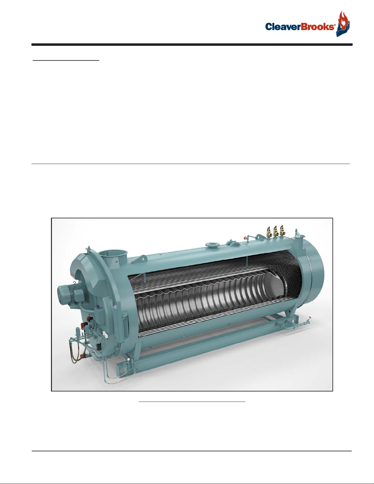
The CBEX-DE boiler is a packaged firetube boiler of welded steel construction and consists of a pressure vessel,
burner, burner controls, forced draft fan, air compressor for oil atomization, oil pump, refractory, and boiler trim
supplied according to customer’s request.
FIGURE 1-1. CBEX-DE cutaway view
Like all CBEX boilers, the CBEX-DE features spiral tubes for enhanced heat transfer. Other features include:
• 30 ppm NOx standard
• Hinged or davited insulated rear door with sight port
750-392
CBEX-DE
1-1
Page 6

Introduction
The CBEX-DE is a 2-pass dry-back design. The flame originates in the furnace. As the combustion gases travel
down the furnace and through the firetubes, heat from the flame and combustion gases is transferred to the
water to generate steam.
For lower emissions the CBEX-DE firetube boiler line is designed to incorporate induced Flue Gas Recirculation
(FGR). FGR may be used when firing either natural gas and/or light oil.
The FGR system mixes a portion of the relatively cool flue gas from the exit of the second-pass tubes with the
incoming combustion air to reduce the furnace flame temperature, thereby reducing NOx emissions. In this
approach, the combustion air fan handles both the combustion air and the recirculated flue gases. Carbon monoxide (CO) emissions also tend to be lower due to increased turbulence caused by the addition of the flue gases
into the combustion air stream.
The low emission design can affect the selection of the combustion air fan, motor, burner, and other components.
Several different system configurations are available, depending on the requirements for NOx emissions and the
fuels used. All systems use similar primary components, but fan and motor sizes as well as the FGR damper may
differ.
Installation should conform to state and local codes. Prior to installation, the proper authorities having jurisdiction are to be consulted, permits obtained, etc.
CBEX-DE boilers offer compliance with multiple insurers’ requirements. Equipment provided may vary depending
on insurance.
Steam boilers are built for a specific design pressure, which is the pressure used in calculating the minimum permissible thickness or physical characteristics of the pressure vessel components. Typically, the safety valves are
set at or below design pressure.
Care taken in placing the pressure vessel into initial service is vital. The waterside of new boilers and new or
remodeled steam or hot water systems may contain oil, grease, or other foreign matter. Waterside care will continue to be important throughout the lifetime of the boiler. A boilout method for new boilers, as well as general
waterside care information, can be found in Chapter 2.
1.1.1 — Construction
Steam boilers designed for 15 psig and hot water boilers designed for 250º F at 125 psi or less are constructed
in accordance with Section IV, Heating Boilers, of ASME Code.
Steam boilers designed for operating pressures exceeding 15 psig are constructed in accordance with Section I,
Power Boilers, of the ASME Code. Hot water boilers designed for operating temperatures above 250º F or 125
psi are likewise built to Section I of the ASME Code.
1-2
750-392
CBEX -DE
Page 7
Component Locations
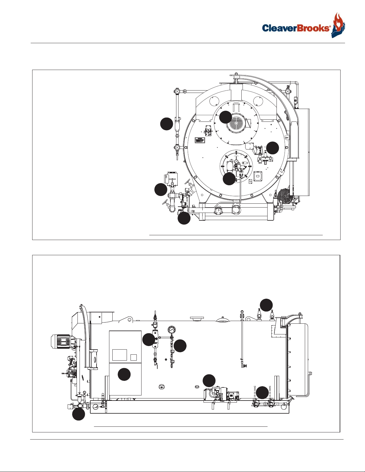
1.2 — Component Locations
1. Blower assembly
2. Feedwater piping
3. Main gas train
4. Burner drawer
5. Oil system
6. Aux low water cutoff
7. Control panel/entrance panel
8. Low water cutoff
9. Pressure controls
1
6
5
4
2
3
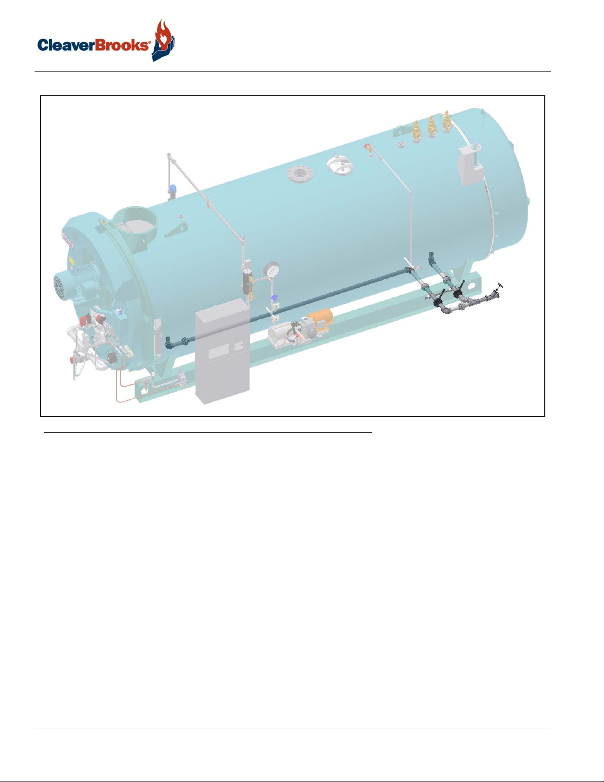
FIGURE 1-2. Boiler front view (67” boiler - configurations may vary)
11. Oil supply piping
12. Air compressor
13. Bottom blowdown piping
750-392
CBEX-DE
10. Safety valves
11
FIGURE 1-3. Boiler side view (67” boiler - configurations may vary)
1
10
8
9
7
12
13
1-3
Page 8
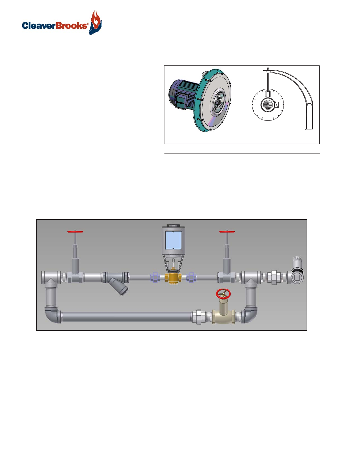
1.2.1 — Blower assembly
The blower assembly, also called the cassette,
comprises the fan and motor and can be removed
as a unit from the front of the boiler without opening the front door. The front davit arm is used to
support the blower cassette during removal.
1.2.2 — Feedwater piping
Introduction
FIGURE 1-4. Fan/motor cassette
Feedwater piping configurations can vary. A typical configuration is shown below, comprising three-valve bypass
piping with strainer and a modulating feedwater valve.
FIGURE 1-5. Feedwater piping
1-4
750-392
CBEX -DE
Page 9
Component Locations
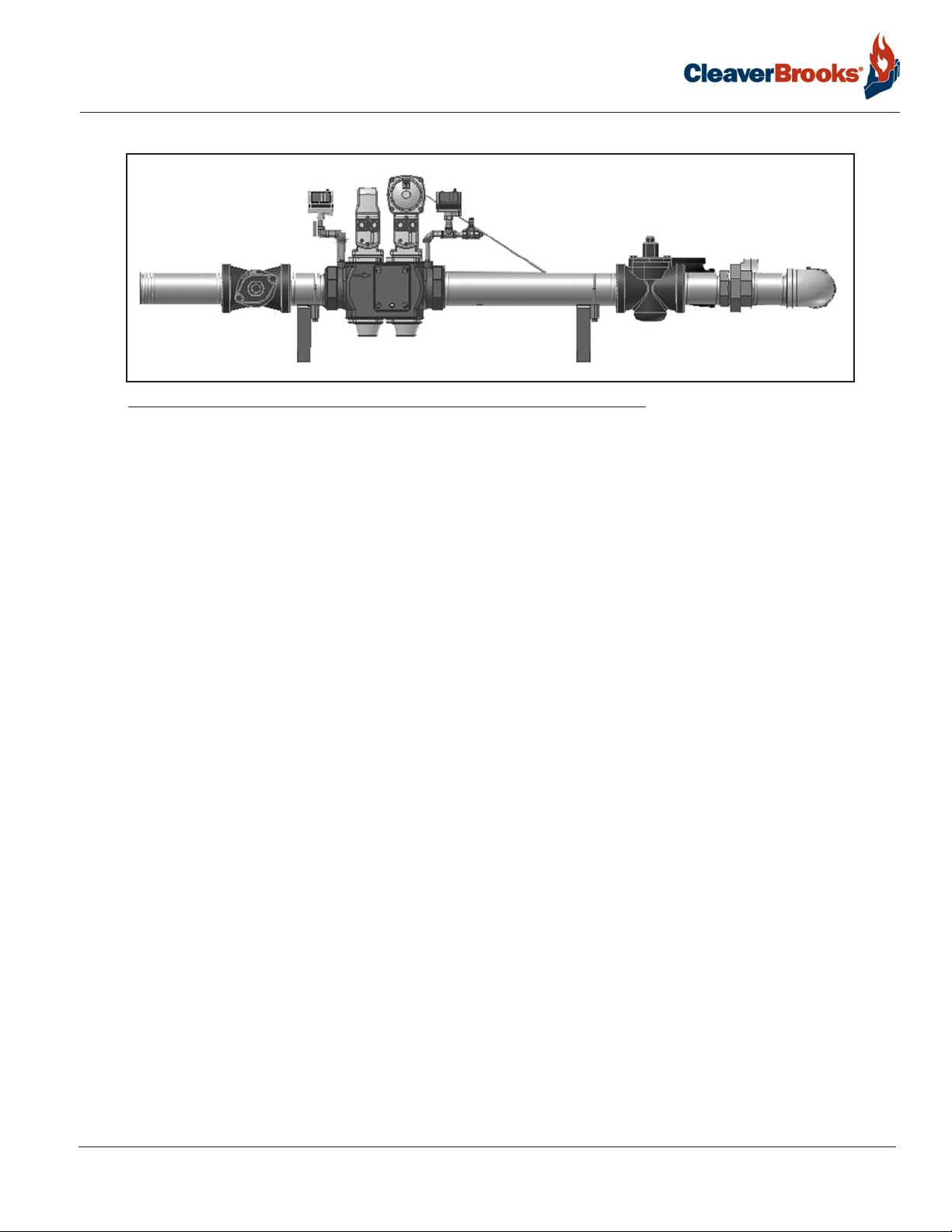
1.2.3 — Main gas train
4
2
5
6
1
1
FIGURE 1-6. Main gas train
Depending upon the requirements of the insurance carrier or other governing agencies, the gas train may consist
of some or all of the following items.
1. Shutoff Cocks: For manually opening and closing the main fuel gas supply downstream of the main gas line
pressure regulator. A second shutoff cock, downstream of the main gas valve(s), is installed to provide a
means of shutting off the gas line whenever a test is made for leakage across the main gas valve.
2. Main Gas Valve: Double body safety shutoff valve. Electrically actuated valves open simultaneously to admit
gas to the burner. The downstream valve is equipped with a with a regulating actuator and a proof of closure
switch that is connected to the pre-ignition interlock circuit.
3. Main Gas Vent Valve (if required): A normally open solenoid valve installed between the two main gas valves
to vent gas to the atmosphere, should any be present in the main gas line when the gas valves are deenergized. The vent valve closes when the gas valves are energized.
4. Low Gas Pressure Switch: A pressure-actuated switch; closed whenever main gas line pressure is above a pre-
selected pressure. Should the pressure drop below the setting, the switch contacts open a circuit causing the
main gas valve(s) to close, or prevent the burner from starting. The switch is usually equipped with a device
that must be manually reset after being tripped.
5. High Gas Pressure Switch: A pressure actuated switch; closed whenever main gas line pressure is below a
preselected pressure. Should the pressure rise above the setting, the switch contacts will open a circuit causing the main gas valve(s) to close, or prevent the burner from starting. The switch is usually equipped with a
device that must be manually reset after being tripped.
6. Test Cocks: The body of the gas valve has 1/4-inch NPT fittings for pressure test connection.
7. Butterfly Gas Valve (not shown): The pivoted disc in the valve is directly driven by a servo motor actuator to
regulate the rate of gas flow to the burner. In optional 700-800 HP single point systems, the valve is driven by
the modulating motor through connecting linkage.
750-392
CBEX-DE
1-5
Page 10
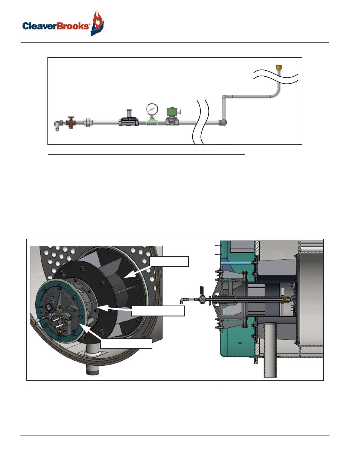
1.2.4 — Pilot train
Introduction
4
3
1
2
FIGURE 1-7. Pilot train
1. Gas Pilot Valve: A solenoid valve that opens during the ignition period to admit fuel to the pilot. It closes after
main flame is established. The sequence of energizing and de-energizing is controlled by the programming
relay. A second gas pilot valve may be required by insurance regulations.
2. Gas Pilot Shutoff Cock: For manually opening or closing the gas supply to gas pilot valve.
3. Gas Pressure Gauge: Indicates gas pressure to pilot.
4. Gas Pressure Regulator: Reduces incoming gas pressure to suit the pilot.
1.2.5 — Burner drawer
GAS HOUSING
BURNER SUPPORT
BURNER DRAWER
FIGURE 1-8. Burner drawer
The burner is a nozzle-mixing orifice design with interrupted gas pilot. Burners equipped for oil use a low pressure, air-atomized oil system.
1-6
750-392
CBEX -DE
Page 11

Component Locations
Combination gas/oil burners include equipment for each fuel, with a fuel selector switch mounted in the control
panel. Regardless of which fuel is used, the burner operates with full modulation within its rated operating range.
The burner returns to minimum firing position for ignition.
The flame safeguard includes a flame detector to supervise both oil and gas flames, and to shut the burner down
in the event of loss of flame. The burner sequence provides a pre-purging period, proving of the pilot and main
flame, and a period of continued blower operation after shutoff to postpurge the boiler of all unburned fuel vapor.
Other safety controls shut down the burner under low-water conditions, excess steam pressure, or water temperature.
Safety interlock controls include combustion and atomizing air proving switches and, depending upon the fuel
and insurance carrier requirements, controls that prove the presence of adequate fuel pressure.
The sequence of burner operation from startup through shutdown is governed by the program relay in conjunction with the operating, limit and interlock devices. The devices are wired into the circuitry to provide safe operation and protect against incorrect operating techniques.
All CBEX-DE boilers have the burner assembly integral with the front head. The burner drawer can be removed as
a unit, or the entire head may be swung open for inspection and maintenance.
Combustion air is provided by a centrifugal blower located in the front head.
Filtered primary air for atomizing fuel oil is furnished independently of combustion air by an air compressor. The
burner control circuit operates on 115 volt, single phase 60 Hz (or 50 Hz when equipped) alternating current.
The forced draft fan motor is generally operated on 3-phase service at the available main power supply voltage.
In addition to the standard basic controls supplied, other devices may be required to meet specific requirements
of an insurance carrier or local code.
Refer to the wiring diagram prepared by Cleaver-Brooks for your installation to determine the specific controls in
the burner and limit control circuits.
750-392
CBEX-DE
1-7
Page 12
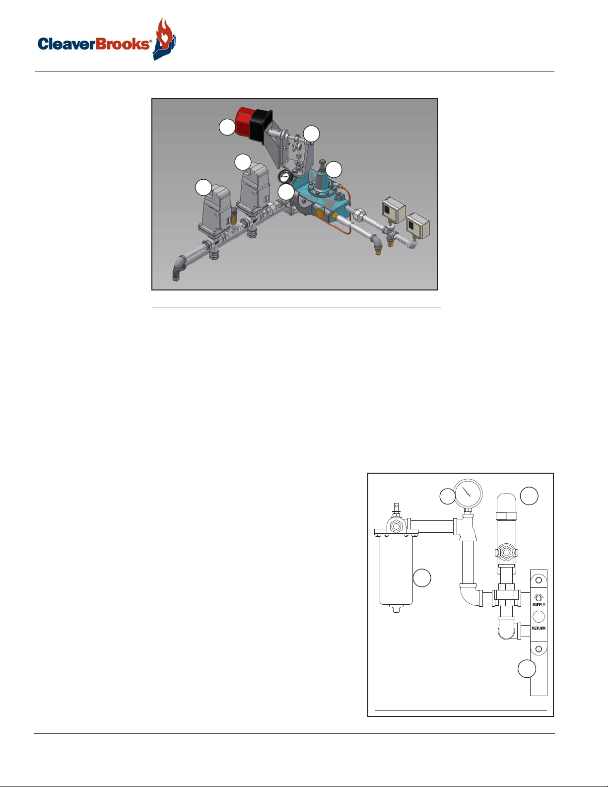
1.2.6 — Oil system
Introduction
2B
2A
1
2D
1
FIGURE 1-9. Front head oil piping
2C
The following items are applicable to all oil fired or gas and oil fired boilers.
1. Oil Shutoff Valve: Opens when energized through contacts in the programmer and allows fuel oil flow from the
oil metering valve to the burner nozzle. A light oil fired burner uses two valves operating simultaneously.
2. Fuel Oil Controller: An assembly combining into a single unit the gauges, regulators and valves required for
regulating the flow of fuel oil. All controllers have the following integral parts.
A - Oil Metering Valve: Valve metering stem moves to increase or decrease the orifice area to regulate the supply of fuel
oil to the burner nozzle in accordance with boiler load variances. Stem movement is controlled by the oil actuator or in
linkage systems by an oil metering cam.
B - Actuator: Positions the oil metering valve stem.
C - Oil Burner Pressure Gauge: Indicates pressure of the fuel oil at the metering valve.
D - Oil Pressure Regulator: For adjustment of the pressure of oil at the metering valve.
3. Oil Relief Valve: Maintains a constant oil supply pressure to the fuel
oil controller by bypassing excess fuel oil.
4. Terminal Block: Provides the connection for fuel oil input and return
to storage tank.
5. Fuel Oil Strainer: Prevents foreign matter from entering the burner
system.
6. Pressure Gauge for oil supply pressure
7. Fuel Oil Pump (not shown): Transfers fuel oil from the storage tank
and delivers it under pressure to the burner system.
1-8
6
5
FIGURE 1-10. Oil terminal block
CBEX -DE
3
4
750-392
Page 13
Component Locations
1.2.7 — Actuators
Individual actuators for fuel, air, and FGR are part of the
standard parallel positioning combustion control system,
and are positioned via Modbus signal from the Hawk control system.
Actuators are connected in series with the air damper actuator last in the sequence. Actuators may use quick disconnect cables or may be hard wired depending on the
installation.
For actuator setup and configuration information as well as
combustion setup procedures, see the appropriate Hawk
controls manual.
FLUE GAS
RECIRCULATION
COMBUSTION AIR
FUEL 2
(FUEL OIL
CONTROLLER)
A single-point positioning linkage system is available for
700/800 HP boilers.
FUEL 1 (GAS BUTTERFLY VALVE)
FIGURE 1-11. Actuators
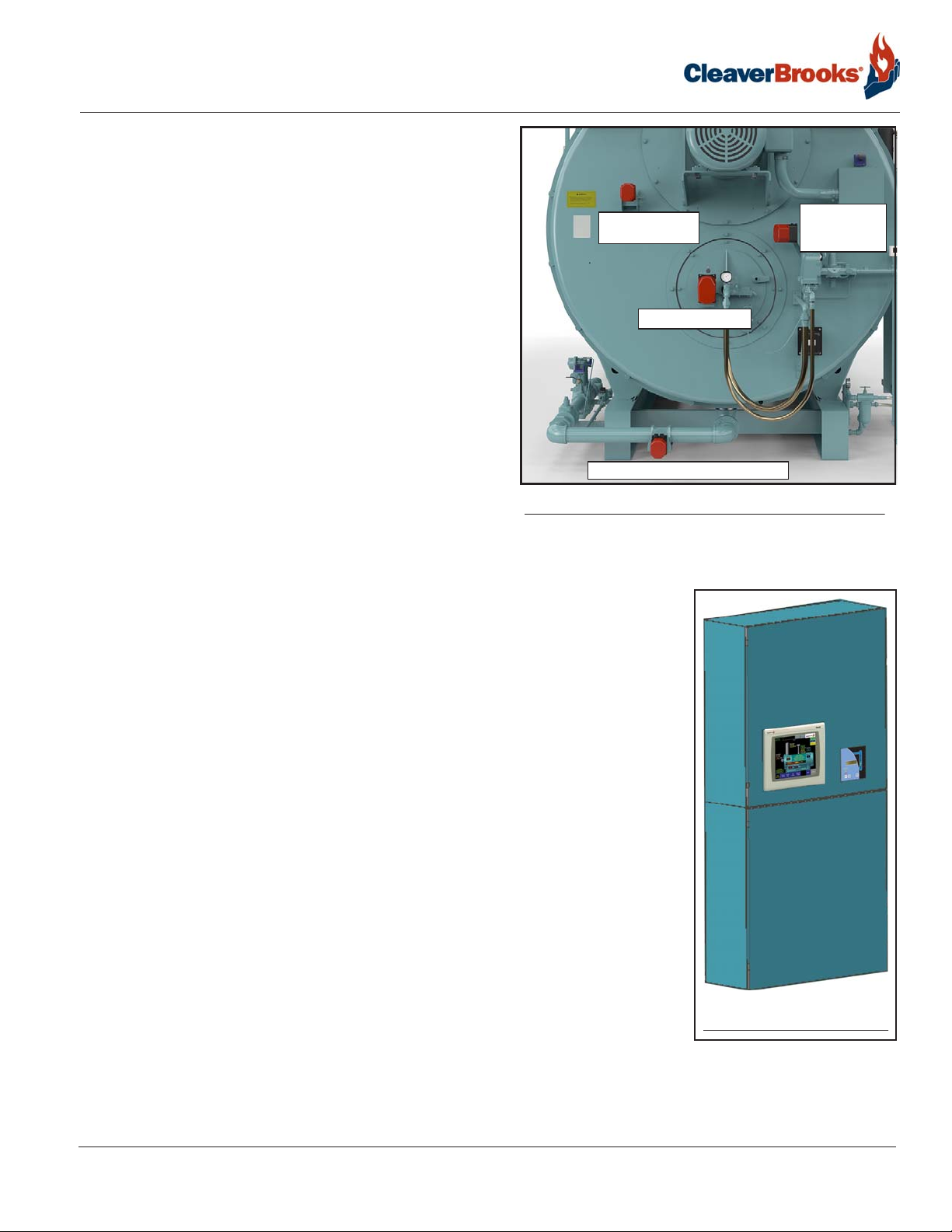
1.2.8 — Control Panel
A common enclosure houses both the control panel and the electrical entrance
panel. The upper and lower sections are divided by a partition with a separate
hinged door for each section.
The upper section (low voltage) houses the boiler control system, including the PLC
and associated modules, the flame safeguard, the Hawk HMI touch screen, and the
LevelMaster panel.
External switches and indicator lights can vary according to options selected. A typical configuration will include switches for:
• FSG reset
• ALWCO reset
• Burner switch
• Fuel selector switch
The standard control system is the Cleaver-Brooks Hawk 1000, which includes a
4” touch screen.
The optional Hawk 4000 features a 7” touch screen, with a 10” screen optional.
FIGURE 1-12. Control/
The principal components of the HAWK 1000 are the Programmable Logic Control-
entrance panel
ler (PLC), touch screen Human Machine Interface (HMI), and the Flame Safety
Control. The system also includes 24VDC power supplies and various relays and circuit breakers.
750-392
CBEX-DE
1-9
Page 14
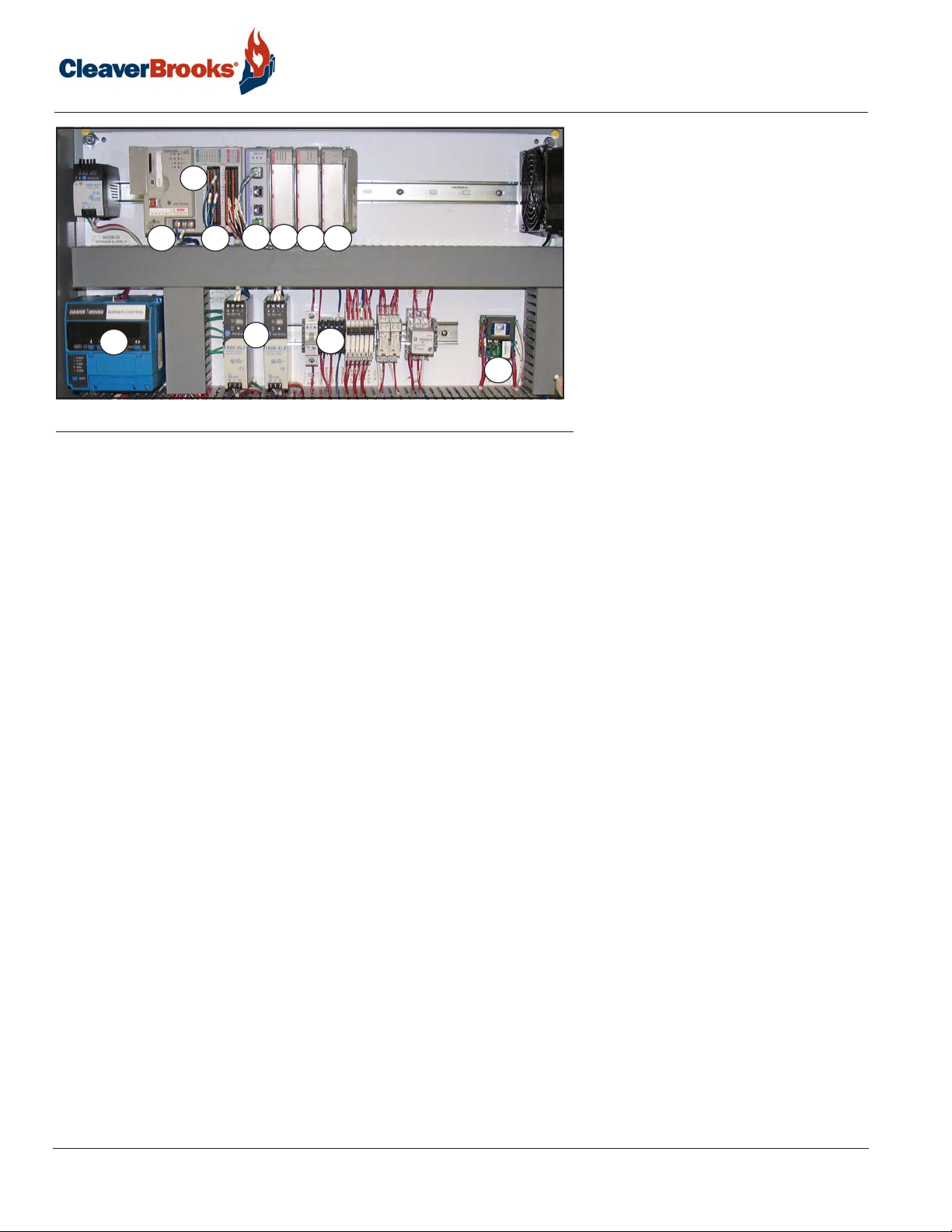
Introduction
1. Base Unit
1
1a
686
1b
2
4
3
5
7
1a. L24ER Programmable Logic Controller (PLC)
1b. Embedded I/O
2. SM2 Modbus Communications Module
3. Digital Inputs
4. Digital Outputs
5. Analog Inputs (optional)
6. Burner Control
7. Power supplies
8. Circuit breakers, relays, fuses,
9. ALWCO control
etc.
9
FIGURE 1-13. Hawk 1000 components, typical
The Base Unit consists of the Processor (CPU) which holds the program logic and configuration for the boiler
controller and embedded I/O modules which consist of discrete inputs, discrete outputs, and analog inputs. The
program logic is password-secured at the factory.
The SM2 module handles the Modbus communications between the PLC and other devices.
The Module Power Supply powers the Base Unit and the I/O modules. The remainder of the PLC rack is for the
discrete input and output modules, and for analog input module (optional).
I/O modules are used to send and receive control and communication signals to/from other parts of the system.
A Right End Cap Terminator is required to complete the modular communication bus. It attaches to the right side
of the last module in the rack.
An optional analog input module can be added to the PLC to provide additional functionality.
The HMI displays numerous boiler parameters at a glance and provides easy menu navigation for configuring
system parameters, setting of combustion, monitoring the boiler processes, and managing and annunciating system alarms.
The HMI communicates with the PLC via Ethernet and is
powered
by a 24
VDC
din-rail mounted power
supply.
NOTE: For complete information on the boiler control system consult the Hawk manual, provided separately.
1-10
750-392
CBEX -DE
Page 15
Component Locations
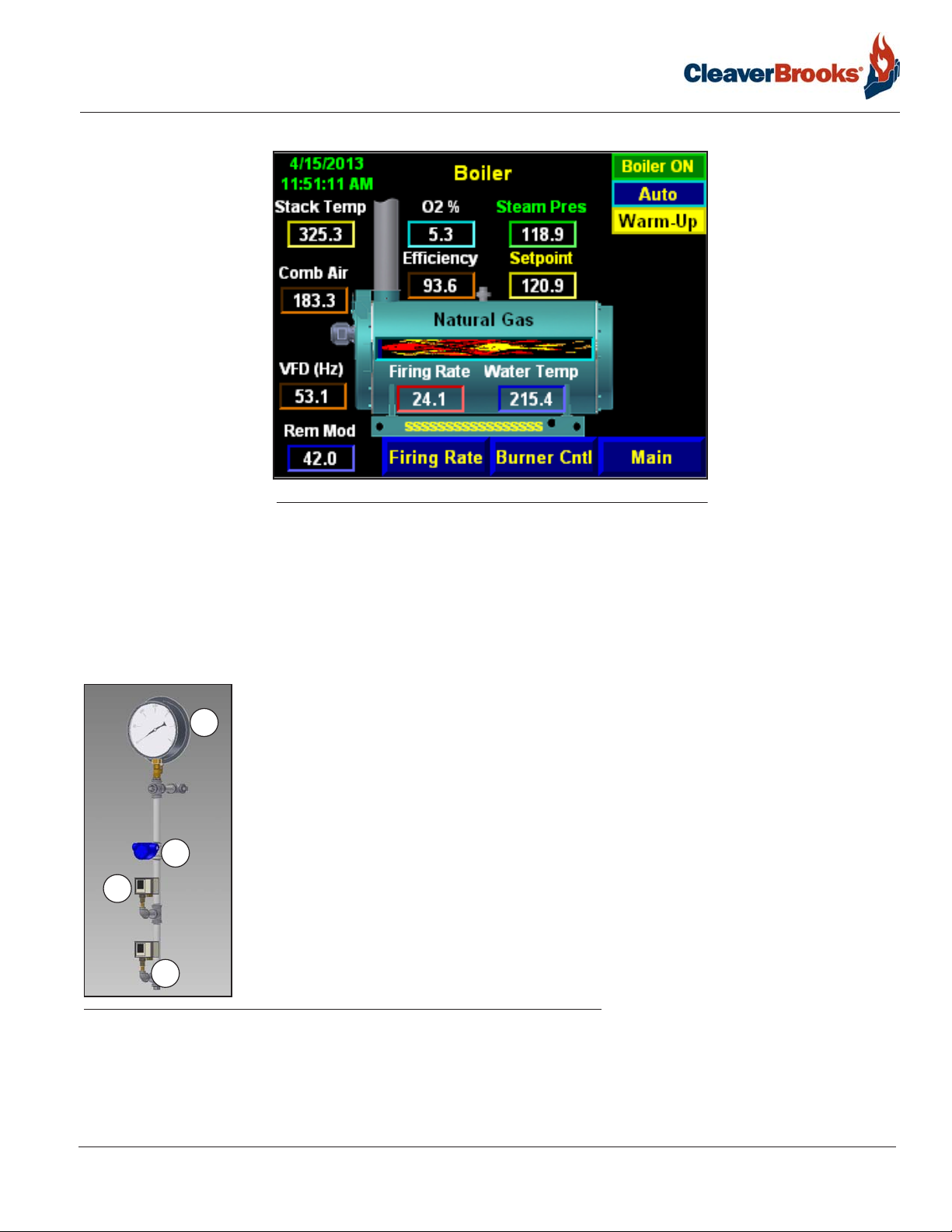
1.2.9 — Pressure Controls
1.Pressure Gauge: Indicates boiler internal pressure.
1
2.Operating Limit Pressure Control: Breaks a circuit to stop burner operation on a rise of
boiler pressure at a selected setting. It is adjusted to stop or start the burner at a preselected pressure setting.
3.High Limit Pressure Control: Breaks a circuit to stop burner operation on a rise of pres-
sure above a selected setting. It is adjusted to stop the burner at a preselected pressure
4
above the operating limit control setting. The high limit pressure control is normally
equipped with a manual reset.
2
4.Pressure Transmitter: Senses changing boiler pressure and transmits a signal to the
boiler control system.
FIGURE 1-14. Boiler Overview screen, Hawk 1000
750-392
CBEX-DE
3
FIGURE 1-15. Steam Controls
1-11
Page 16
Introduction
1.2.10 — Temperature Controls (hot water boilers)
High Limit Temperature Control: Breaks a circuit to stop burner operation on a rise of temperature at a selected
setting. It is adjusted to stop the burner at a preselected temperature above the operating control setting. The
high limit temperature control normally is equipped with a manual reset.
Operating Limit Temperature Control: Breaks a circuit to stop burner operation on a rise of boiler temperature at
a selected setting. It is adjusted to stop or start the burner at a preselected operating temperature.
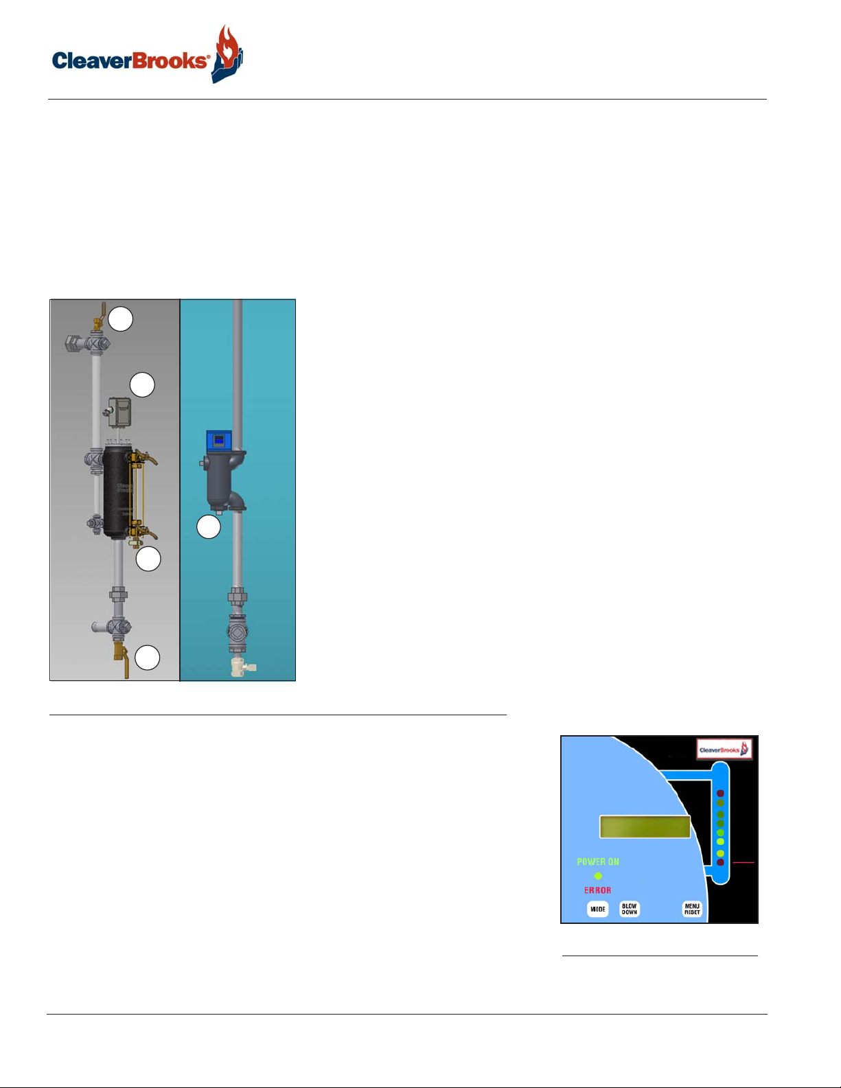
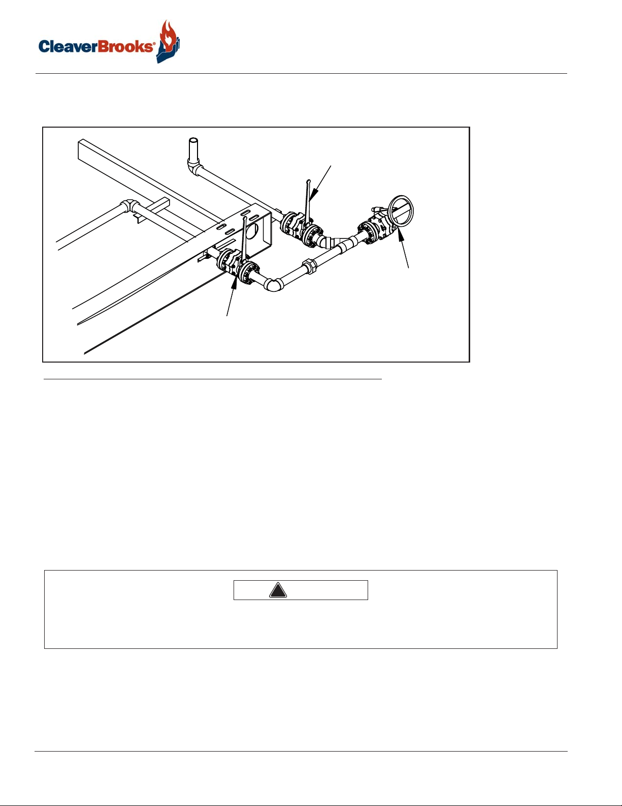
1.2.11 — Water Level Controls
The Low Water Cutoff (LWCO) shuts down the burner if water level goes
3
below the safe operating point. The LWCO is also responsible for starting
and stopping the feedwater pump to maintain the proper boiler water
level. The Cleaver-Brooks Level Master is the standard LWCO on CBEXDE boilers.
1
1.Low Water Cutoff and Pump Control: Float-operated control responds to the water
level in the boiler. It performs two distinct functions:
•Stops firing of the burner if water level lowers below the safe operating point. Energizes
the low-water light in the control panel; also causes low-water alarm bell (optional
equipment) to ring. Code requirements of some models require a manual reset type of
ALWCO
low water cutoff.
•Starts and stops the feedwater pump (if used) to maintain water at the proper operat-
ing level.
LWCO
5
2
4
2.Water Gauge Glass Drain Valve: Provided to flush the gauge glass.
3.Vent Valve: Allows the boiler to be vented during filling and facilitates routine boiler
inspection as required by ASME Code.
4.Water Column Drain Valve: Provided so that the LWCO and its piping can be flushed
regularly to assist in maintaining cross-connecting piping and in keeping the float bowl
clean and free of sediment. A similar drain valve is furnished with the auxiliary low water
cutoff.
5.The Auxiliary Low Water Cutoff (ALWCO) stops burner operation in the event boiler
water drops below the primary low water cutoff point. May require manual reset in order
to restart the boiler after a low water condition.
FIGURE 1-16. Low Water Cutoff, Aux. Low Water Cutoff
Level Master safety features include float detection, routines for water column
blowdown and ALWCO testing, and an independent watchdog system for
shutdown in the event of microprocessor failure. An internal clock provides
time-stamped event logging for all blowdown cycles and alarm occurrences.
The Level Master keypad/display unit is mounted in the control panel next to
the Hawk HMI. A bar graph provides a continuous reading of water level,
while a two row backlit LCD display shows controller messages. The sensor
component is mounted in the water column and can be easily removed for
inspection or cleaning.
Expanded programming features can be accessed via RS-232 computer connection.
For further information see the Level Master manual provided separately.
1-12
FIGURE 1-17. Level Master
display
750-392
CBEX -DE
Page 17
Component Locations
1.2.12 — Bottom blowdown piping
Quick and slow opening valves are provided as standard for bottom blowdown. See Chapter 2 for procedure.
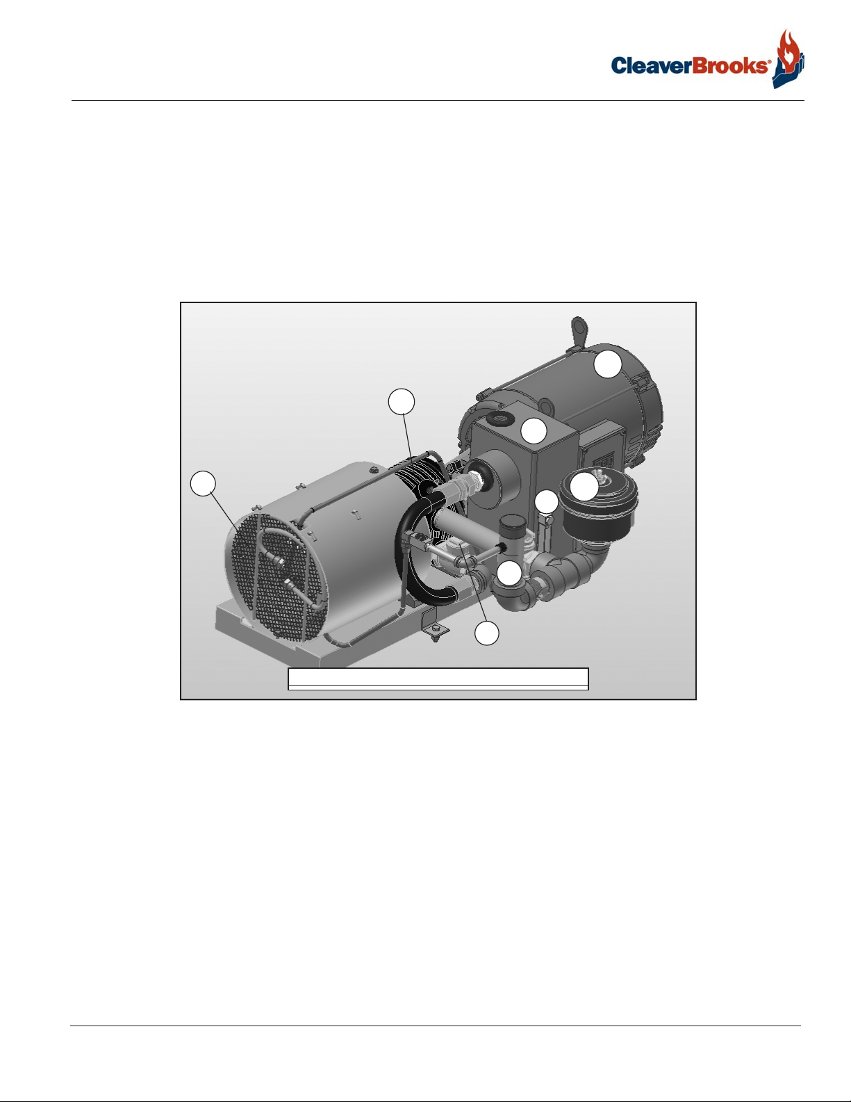
1.2.13 — Air Compressor
A side mounted air compressor provides atomizing air when burning #2 oil. It is started automatically by the
combustion control system. It includes the following components:
1
2
5
7
3
6
8
4
FIGURE 1-18. Air compressor
1. Air Pump Motor: Drives the air pump and an air cooling fan. The motor is started and stopped simultaneously
with the forced draft fan motor.
2. Air Pump: Provides air for atomization of the fuel oil.
3. Air Filter: The filter cleans the air supply prior to entering air pump.
4. Check Valve: Prevents lubricating oil and compressed air from surging back through the pump and air filter
when the pump stops.
5. Air-Oil Receiver Tank: Holds a supply of oil for lubricating the air pump. The receiver tank also separates lube
oil from the atomizing air before delivery to nozzle.
6. Lube Oil Level Sight Glass: Indicates the level of lubricating oil in the air-oil receiver tank.
7. Lube Oil Cooling Coil: Cools the lubricating oil before it enters the air pump. A fan driven by the air pump
motor circulates cooling air over the coil.
8. Lube Oil Fill Pipe and Strainer: Used when adding oil to the air-oil receiver tank.
750-392
CBEX-DE
1-13
Page 18
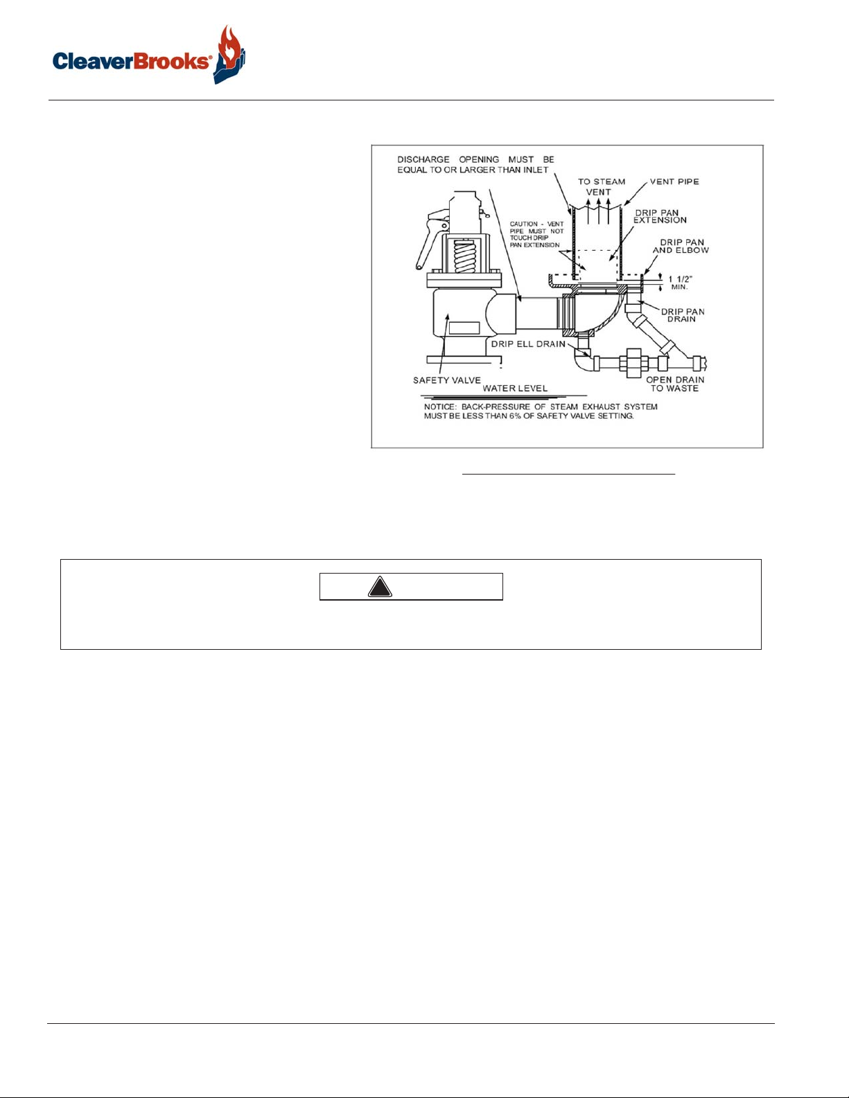
1.2.14 — Safety Valve(s)
Safety valves prevent pressure in excess of the
design pressure of the vessel. The size, rating,
and number of valves on a boiler is determined
by the ASME Boiler Code. The safety valves
and the discharge piping are to be installed to
conform to the ASME Code requirements. The
installation of a valve is of primary importance
to its service life. A valve must be mounted in a
vertical position so that discharge piping and
code-required drains can be properly piped to
prevent buildup of back pressure and accumulation of foreign material around the valve seat.
Apply only a moderate amount of pipe compound to male threads and avoid over-tightening, which can distort the seats. Use only flatjawed wrenches on the flats provided. When
installing a flange connected valve, use a new
gasket and draw the mounting bolts down
evenly. Do not install or remove side outlet
valves by using a pipe or wrench in the outlet.
Introduction
FIGURE 1-19. Safety Valve Piping
The vent pipe should be supported so as to
ensure no pressure is exerted on the safety valve discharge piping.
Warning
!
Only properly certified personnel should adjust or repair the boiler safety valves. Failure to follow these instructions
could result in serious injury or death.
1-14
750-392
CBEX -DE
Page 19
CHAPTER 2 Waterside Care
The operator should be familiar with this chapter before attempting to place the unit into operation.
Although it is of prime importance, the subject of water supply and treatment cannot thoroughly be covered
within the scope of this manual. For additional assistance with your water treatment needs, contact your CleaverBrooks service and parts representative. Ultimately a water treatment expert should be consulted to obtain the
best treatment plan for your location.
Feedwater equipment should be ready for use upon installation of the boiler. Be sure that all valves, piping, boiler
feed pumps, and receivers are installed in accordance with prevailing codes and practices.
Strict attention to waterside care is essential during initial commissioning and throughout the lifetime of the
boiler. When placing the pressure vessel into initial service, keep in mind that the waterside of new boilers and
new or remodeled steam systems may contain oil, grease or other foreign matter. A method of boiling out the vessel to remove the accumulations is described later in this chapter.
2.1 — Water requirements - steam boilers
Feed Pump Operation
Before turning on the pump motor be certain that all valves in the water feed line are open to prevent possible
damage to the feed pump mechanism. After opening the valves, momentarily energize the feed pump motor to
establish correct pump rotation. With the correct rotation established, close the boiler feed pump entrance
switch. The pump should shut down when the water level reaches the proper level.
Feedwater pumps must have adequate capacity to maintain required water level under all operating conditions.
Check the feedwater pumps periodically and maintain as necessary to prevent unexpected breakdowns.
NOTE: Prior to operating the pump, carefully check the alignment of the flexible coupling, if one is used. A properly
aligned coupling will last a long time and provide trouble-free mechanical operation.
NOTE: For new installations a startup strainer is recommended. Contact the pump manufacturer for details.
NOTE: In the event that water column isolation valves are provided, it must be established that the valves are open
and seated or locked in the open position. It is illegal to operate the boiler with closed or unseated open valves.
750-392
CBEX-DE
2-1
Page 20

Waterside Care
Warning
!
The isolation valves and the water column piping must be locked open during operation. Failure to do so may result
in a low water condition. Failure to follow these instructions could result in serious injury or death.
2.2 — Water requirements - hot water boilers
Air Removal - The hot water outlet includes a dip tube which extends 2 to 3 inches into the boiler. The dip tube
reduces the possibility of air, which may be trapped at the top of the shell, from entering the system. Oxygen or
air released in the boiler will collect or be trapped at the top of the boiler shell.
The air vent tapping on the top center line of the boiler should be piped into the expansion or compression tank.
Air trapped at the top of the boiler will find its way out of the boiler through the tapping.
Minimum Water Temperature - The minimum recommended boiler water temperature is 170 deg F. When water
temperatures lower than 170 deg F are used, the combustion gases are reduced in temperature to a point where
water vapor condenses, causing corrosion in the boiler and possible breeching. Condensation is more severe on a
unit that operates intermittently and which is greatly oversized for the actual load. Condensation can be minimized by maintaining boiler water temperatures above 170 deg F.
Notice
References to hot water boilers in this manual apply only to boilers using 100% water. Glycol solutions have
different operating requirements, circulation rates and temperatures, etc.
Rapid Replacement of Boiler Water - The system layout and controls should be arranged to prevent the possibil-
ity of pumping large quantities of cold water into a hot boiler, which will cause thermal stresses. Water temperature in a boiler of 200 deg F or 240 deg F cannot be completely replaced with 80 deg F water in a few minutes
time without causing thermal stress. The same fact applies to periods of normal operation, as well as during initial start-up.
The circulating pumps should be interlocked with the burner so that the burner cannot operate unless the circulating pump is running in order to avoid damage to the equipment.
When individual zone circulating pumps are used, it is recommended that they be kept running-even though the
heat users do not require hot water. The relief device or by-pass valve will thus allow continuous circulation
through the boiler and can help prevent rapid replacement of boiler water with cold zone water.
Continuous Flow Through the Boiler - The system should be piped and the controls arranged to allow water circulation through the boiler under all operating conditions. The operation of three-way valves and system controls
should be checked to be sure that the boiler will not be by-passed. Constant circulation through the boiler
eliminates the possibility of stratification within the unit and results in more even water temperatures to the system. A rule of thumb of 3/4 to 1 gpm per boiler horsepower can be used to determine the minimum continuous
flow rate through the boiler under all operating conditions. The operator should determine that a flow of water
exists through the boiler before initial firing or refiring after boiler has been drained.
2-2
750-392
CBEX-DE
Page 21
Water requirements - hot water boilers
Water Circulation - The chart in Table 2-1 shows the maximum gpm circulation rate of boiler water in relation to
full boiler output and system temperature drop.
It is advisable to have a thermometer installed in the return line to indicate return water temperature. Knowing
the supply water temperature, the boiler system differential can be established. With knowledge of the pumping
rate, the operator can easily detect any excessive load condition and take appropriate corrective action.
Multiple Boiler Installations - When multiple boilers are used, care must be taken to ensure adequate or proportional flow through the boilers. Proportional flow can best be accomplished by use of balancing valves and
gauges in the supply line from each boiler. If balancing valves or orifice plates are used, a significant pressure
drop (e.g., 3-5 psi) must be taken across the balancing device to accomplish the purpose. If care is not taken to
ensure adequate or proportional flow through the boilers, wide variations in firing rates between the boilers can
result. In extreme cases, one boiler may be in the high-fire position while the other boiler or boilers may be at low
fire. The net result would be that the common header water temperature to the system would not be up to the
desired point.
Note: If the operating water temperature going to the system must be lower than 170 deg F, mixing valves
should be used to avoid damage to the equipment. Operating boiler water temperature should be a minimum
of 170 deg F (200 deg F if used to preheat No. 6 oil).
TABLE 2-1. Maximum Circulating Rate
BOILER SIZE
(BHP)
250 8,370 1,675 838 558 419 335 280 240 210 186 167
300 10,045 2,010 1,005 670 503 402 335 287 251 223 201
350 11,720 2,350 1,175 784 587 470 392 336 294 261 235
400 13,400 2,680 1,340 895 670 535 447 383 335 298 268
500 16,740 3,350 1,675 1,120 838 670 558 479 419 372 335
600 20,080 4,020 2,010 1,340 1,005 805 670 575 502 448 402
700 23,430 4,690 2,345 1,565 1,175 940 785 670 585 520 470
800 26,780 5,360 2,680 1,785 1,340 1,075 895 765 670 595 535
BOILER
OUTPUT
BTU/HR
(1000)
SYSTEM TEMPERATURE DROP - DEGREES °F
10 20 30 40 50 60 70 80 90 100
MAXIMUM CIRCULATING RATE - GPM
Pump Location - It is recommended that the system circulating pumps take suction from the outlet connection
on the boiler, and that they discharge to the system load. In order to put the boiler and the expansion tank on the
suction side of the pump. The suction side is preferred because it decreases air entry into the system and does
not impose the system head on the boiler. It is common practice to install a standby system circulating pump.
The main circulating pumps are usually located adjacent to the boilers in the boiler room.
Pump Operation - Pumps are normally started and stopped by manual switches. It is also desirable to interlock
the pump with the burner so that the burner cannot operate unless the circulating pump is running.
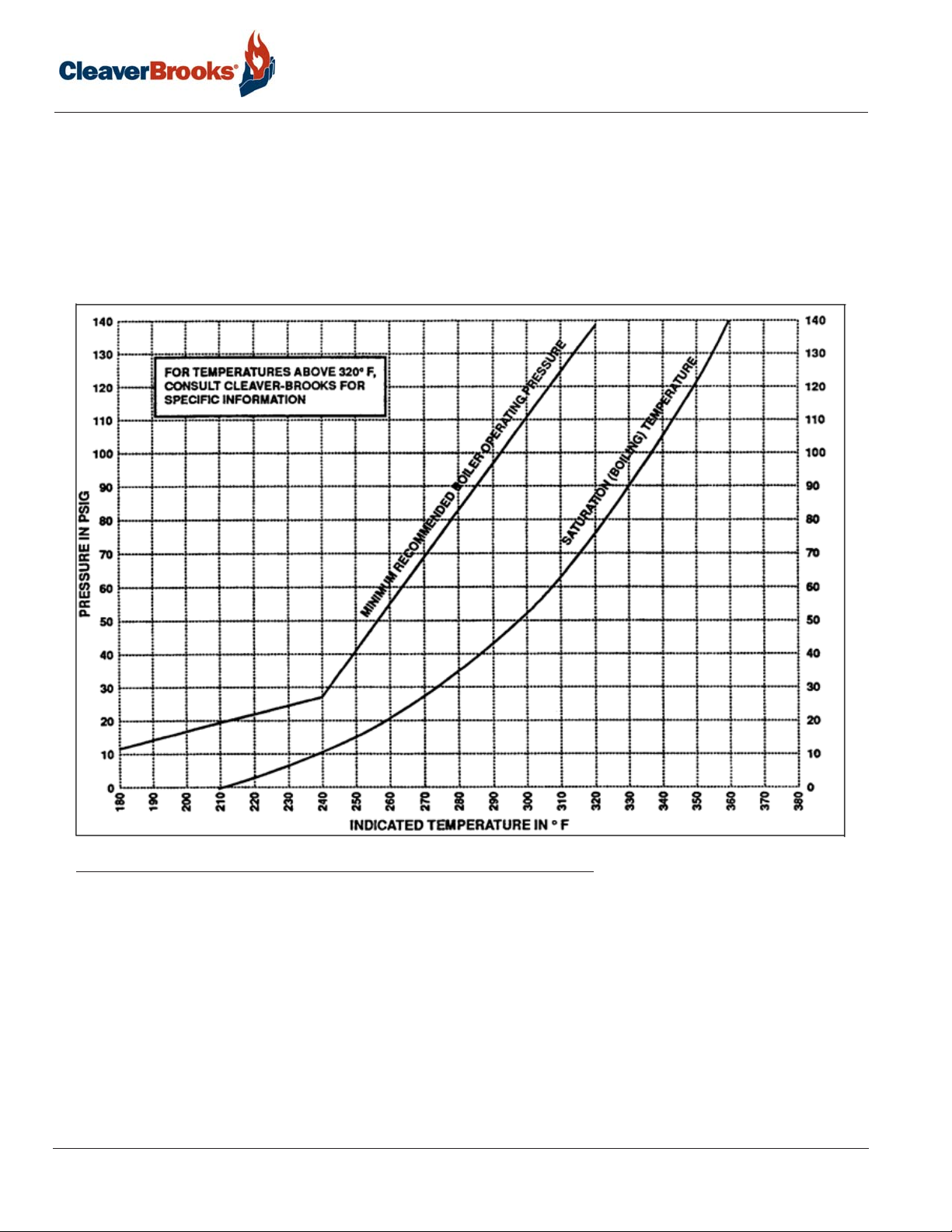
Pressure - The design of the system and usage requirements often dictate the pressure exerted upon the boiler.
Some systems are pressurized with air, or with an inert gas such as nitrogen. Caution must be exercised to
ensure that the proper relationship of pressure to temperature exists within the boiler so that all of the boiler’s
internal surfaces are fully wetted at all times.
750-392
CBEX-DE
2-3
Page 22
Waterside Care
When initially firing a newly installed boiler, or when cutting an existing boiler into an operating system, the
boiler or boilers to be cut into operation MUST be pressurized equal to the system and/or other boilers prior to
opening the header valves.
Special caution must be taken to guard against any condition, or combination of conditions, that might lead to
the transfer of cold water to a hot boiler or hot water to a cold boiler. It cannot be overemphasized that rapid
changes in temperature within the boiler can cause damage.
FIGURE 2-1. Internal Boiler Pressure
2.3 — Water Treatment
Properly treated boiler feed water, combined with good engineering and operating practices, leads to maximum
effectiveness and long life of pressure vessels. Contact your local Cleaver-Brooks authorized representative for
information on how to prevent the presence of unwanted solids and corrosive gases.
Objectives of water treatment are:
1. Prevent hard scale deposits or soft sludge deposits, which reduce heat transfer and can lead to overheated
metal and costly downtime and repairs.
2-4
750-392
CBEX-DE
Page 23

Cleaning
2. Eliminate corrosive gases in the supply or boiler water.
3. Prevent inter-crystalline cracking or caustic embrittlement of boiler metal.
4. Prevent carryover and foaming.
Accomplishment of the above objectives generally requires proper feedwater treatment before and after introduction of the water into the boiler. The selection of pre-treatment processes depends upon the water source, its
chemical characteristics, amount of makeup water needed, plant operating practices, etc. Treating methods
include filtering, softening, de-mineralizing, deaerating, and preheating. After-treatment involves chemical treatment of the boiler water. A water treatment expert should be consulted to determine an appropriate treatment
program.
Because of the variables involved, no single boiler compound can be considered a “cure-all” nor is it advisable to
experiment with homemade treating methods. Sound recommendations and their employment should be augmented by a periodic analysis of the feedwater, boiler water, and condensate.
The internal or waterside surfaces of the pressure vessel should be inspected with enough frequency to determine
the presence of any contamination, accumulations of foreign matter, or corrosion, and/or pitting. If any of the conditions are detected, contact your local Cleaver-Brooks authorized representative for advice on corrective action.
A properly sized water meter should be installed in the raw water make-up line in order to accurately determine
the amount of raw water admitted to the boiler (steam or hot water) and to aid in maintaining proper waterside
conditions.
2.4 — Cleaning
2.4.1 — Steam/Hot Water Piping
Steam piping systems connected to the boiler may contain oil, grease, or foreign matter. The impurities must be
removed in order to prevent damage to pressure vessel heating surfaces. On a steam system, the condensate
should be wasted until tests show the elimination of undesirable impurities. During the period that condensate is
wasted, attention must be given to the treatment of the raw water used as make-up so that an accumulation of
unwanted materials or corrosion does not occur. For more information, contact your local Cleaver- Brooks authorized representative.
On a hot water system, chemical cleaning is generally necessary and the entire system should be drained after
treatment. A chemical treatment expert should be consulted regarding the best product for your application.
2.4.2 — Pressure Vessel
The waterside of the pressure vessel must be kept clean from grease, sludge, and foreign material. Such deposits, if present, will shorten the life of the pressure vessel, will interfere with efficient operation and functioning of
control and safety devices, and quite possibly cause unnecessary and expensive rework, repairs, and downtime.
The installation and operating conditions that the boiler will be subjected to should be considered and cleaning of
the waterside of the pressure vessel should be provided during the course of initial start-up.
The pressure vessel and the steam and return lines or hot water piping represent, in effect, a closed system.
Although the steam and return (condensate) lines or the hot water piping system may have been previously
cleaned, it is possible that:
1. Cleaning has been inadequate.
750-392
CBEX-DE
2-5
Page 24
Waterside Care
2. Partial or total old system is involved.
3. Conditions may prevent adequate cleaning of piping.
The pressure vessel waterside should be inspected on a periodic basis. An inspection will reveal true internal
conditions and serve as a check against conditions indicated by chemical analysis of the boiler water. Inspection
should be made three months after initial starting and at regular 6-, 9-, or 12-month intervals thereafter. The frequency of further periodic inspections will depend upon the internal conditions found.
If any unwanted conditions are observed, contact your local Cleaver-Brooks authorized representative for recommendations.
Any sludge, mud, or sediment found will need to be flushed out. If excessive mud or sludge is noticed during
blowdown, the scheduling or frequency of blowdown may need to be revised. The need for periodic draining or
washout will also be indicated.
Any oil or grease present on the heating surfaces should be removed promptly by a boil-out using an alkaline
detergent solution.
2.5 — Boil-Out of a New Unit
The internal surfaces of a newly installed boiler may have oil, grease or other protective coatings used in manufacturing. Such coatings must be removed because they lower the heat transfer rate and could cause overheating
of a tube. Before boiling out procedures may begin, the burner should be ready for firing. The operator must be
familiar with the procedure outlined under burner operation.
NOTE: Temperature of initial fill of water for hydrostatic tests, boil-out, or for normal operation should be as stated in
the ASME Boiler Code.
Warning
!
Use of a suitable face mask, goggles, rubber gloves, and protective garments is strongly recommended when handling or mixing caustic chemicals. Do not permit the dry material or the concentrated solution to come in contact
with skin or clothing. Failure to follow these instructions could result in serious injury or death.
A general procedure for cleaning a boiler is:
1. Refer to the table below to determine water capacity. Have sufficient cleaning material on hand to complete
the job.
TABLE 2-2. Water Capacity and Weights
Boiler HP
250 300 350 400 500 600 700 800
Water Volume - Operating, Gal. 1126 1190 1199 2032 1725 1968 1767 1837
Water Volume - Flooded, Gal. 1589 1680 1718 2618 2515 2869 2630 2733
Water Weight - Operating, lbs. 9378 9915 9991 16926 14366 16393 14723 15300
Water Weight - Flooded, lbs. 13240 13996 14315 21805 20952 23899 21909 22765
2-6
750-392
CBEX-DE
Page 25
Boil-Out of a New Unit
2. All valves in the piping leading to or from the system must be closed to prevent the cleaning solution from get-
ting into the system.
3. When dissolving chemicals:
A. Put warm water into a suitable container.
B. Slowly introduce the treatment chemical into the water.
C. Add the chemical slowly and in small amounts to prevent excessive heat and turbulence.
4. Water relief valves and steam safety valves must be removed before adding the boilout solution so that neither
the boilout solution nor the grease the solution may carry will contaminate the valves. Use care in removing
and reinstalling the valves.
5. An overflow pipe should be attached to one of the top boiler openings and routed to a safe point of discharge.
The safety valve tapping is usually used.
6. Fill the pressure vessel with clean water at ambient temperature until the top of the tubes are covered. Add
the cleaning solution, slowly and in small amounts, and then fill to the top with water.
7. The boiler should then be fired intermittently at a low rate sufficient to hold solution just at the boiling point.
Boil the water for at least five hours. Do not produce steam pressure.
8. Allow a small amount of fresh water to enter the boiler to create a slight overflow that will carry off surface
impurities.
9. Continue the boil and overflow process until the water clears. Shut the burner down.
10. Let the boiler cool to 120º F or less.
11. Remove handhole plates and wash the waterside surfaces thoroughly using a high pressure water stream.
12. Inspect the surfaces. If they are not clean, repeat the boilout.
13. After closing the handholes and reinstalling the safety or relief valves, fill the boiler and fire it until the water is
heated to at least 180º F to drive off any dissolved gases, which might otherwise corrode the metal.
14. Local authorities and chemical supplier should be consulted as to boil out chemical disposal.
Warning
!
Be sure to drain the hot water to a safe point of discharge to avoid scalding. Failure to follow these instructions could
result in serious injury or death.
The above procedure may be omitted in the case of a unit previously used or known to be internally clean. However, consideration must be given to the possibility of contaminating materials entering the boiler from the system.
NOTE: For new installations, refractory heat-curing can be accomplished at the same time as the boil out. Total firing
time (firing intermittently at a low rate) should be 6-8 hours. The heat curing procedure is essential to prevent damage and cracking in the boiler refractory.
750-392
CBEX-DE
2-7
Page 26
Waterside Care
Caution
!
AIR-DRYING ALONE WILL NOT SUFFICIENTLY ENSURE AGAINST REFRACTORY DAMAGE. HEAT-CURING
MUST BE PERFORMED AT INITIAL START-UP. RUN THE BURNER AT LOW FIRE FOR A PERIOD OF 6 TO 8
HOURS. AFTER THIS TIME THE FIRING RATE MAY BE GRADUALLY INCREASED. FAILURE TO FOLLOW THIS
PROCEDURE MAY RESULT IN DAMAGE AND CRACKS IN THE REFRACTORY.
Important
!
There are three approximately 1/4 inch holes provided along the bottom of the rear head to remove
water from the refractory curing process. These holes should be sealed shut with a high temperature
caulk upon completion of the refractory cure procedure.
2.6 — Washing Out
2.6.1 — Steam Boiler
No later than three months after initially placing the boiler into operation, and thereafter as conditions warrant,
the pressure vessel should be drained after being properly cooled to near ambient temperature. Handhole covers
should be removed and waterside surfaces should be inspected for corrosion, pitting, or formation of deposits.
Upon completion of the inspection, the pressure vessel interior should be flushed out, as required, with a high
pressure hose. If deposits are not fully removed by flushing, a consultation may be required with your local
Cleaver-Brooks authorized representative. In extreme cases, it may be necessary to resort to acid cleaning. Professional advice is recommended if acid cleaning is required.
The inspections will indicate the effectiveness of the feedwater treatment. The effectiveness of treatment, the
water conditions, and the amount of fresh water make-up required are all factors to be considered in establishing
frequency of future pressure vessel washouts. Contact your local Cleaver-Brooks authorized representative for
more information.
2.6.2 — Hot Water Boiler
In theory, a hot water system and boiler that has been initially cleaned, filled with raw water (and water treated),
and with no make-up water added, will require no further cleaning or treatment. However, since the system (new
or old) can allow entrance of air and unnoticed or undetected leakage of water, introductions of raw water makeup or air may lead to pitting, corrosion and formation of sludge, sediment, scale, etc., on the pressure vessel
waterside. If the operator is absolutely certain that the system is tight, then an annual waterside inspection may
be sufficient. However, if there is any doubt, the pressure vessel waterside should be inspected no later than
three months after initially placing the boiler into operation, and periodically thereafter as indicated by conditions
observed during inspections.
2-8
750-392
CBEX-DE
Page 27

Blowdown - Steam Boilers
! Warning
Be sure to drain the hot water to a safe point of discharge to avoid scalding. Failure to follow these
instructions could result in serious personal injury or death
2.7 — Blowdown - Steam Boilers
Boiler water blowdown is the removal of some of the concentrated water from the pressure vessel and its replacement with feedwater so that the lowering of concentration of dissolved solids in the boiler water occurs.
Dissolved solids are brought in by the feedwater even though the water may be treated prior to use through external processes that are designed to remove unwanted substances which contribute to scale and deposit formations. However, none of the processes can remove all substances. Regardless of their efficiency, some dissolved
solids will be present in the boiler feedwater.
Dissolved solids become less soluble in the high temperature of the boiler water and tend to accumulate on heating surfaces. Therefore blowdown and internal chemical treatment are required to prevent the solids from forming harmful scale and sludge.
Scale has a low heat transfer value and acts as an insulation barrier. Scale retards heat transfer, which not only
results in lower operating efficiency, and consequently higher fuel consumption, but equally important, can cause
overheating of boiler metal. Overheating of boiler metal can result in tube failures or other pressure vessel metal
damage and lead to boiler downtime and costly repairs.
Scale is caused primarily by calcium and magnesium salts, silica and oil. Any calcium and magnesium salts in
the boiler water are generally precipitated by the use of sodium phosphate, along with organic materials, to
maintain the precipitates or “sludge” in a fluid form. The solids such as sodium salts and suspended dirt do not
readily form scale. But as the boiler water boils off as relatively pure steam, the remaining water is thickened
with the solids. If the concentration is permitted to accumulate, the sludge will build possibly causing overheating of the metal.
Therefore, it is necessary to control the amounts of totally dissolved solids (TDS) and sludge in the following
ways.
2.7.1 — Types of Blowdown
The two principal types of blowdown are intermittent manual blowdown and continuous blowdown.
Intermittent Manual Bottom Blowdown
Manual or sludge blowdown is necessary for the operation of the boiler whether or not continuous blowdown is
employed.
The blowdown tappings are located at the bottom or lowest part of the boiler in order to rid the sludge in the
lower part of the vessel.
750-392
CBEX-DE
2-9
Page 28
Waterside Care
FIGURE 2-2. Bottom blowdown piping
Equipment generally consists of two quick opening valves and one slow opening valve. The valves and necessary
piping are not normally furnished with the boiler. but supplied by others. All piping must be routed to a safe point
of discharge. Piping must be properly supported and free to expand.
Continuous Blowdown
Continuous blowdown is used in conjunction with a surface blowoff tapping (furnished on units 60” in diameter
and larger) on the top center line of the pressure vessel. It is provided with an internal collecting pipe terminating
slightly below the working water level for the purpose of skimming dissolved solids, oil, or other impurities from
the surface of the pressure vessel water.
A controlled orifice valve or an auto-sensing/metering valve is used to allow a continual, yet controlled flow of
concentrated water to drain or a place of recovery.
The flow control valve and piping are generally provided by others. All piping must be routed to a safe point of
discharge.
2.7.2 — Frequency of Manual Blowdown
When continuous blowdown is utilized, manual blowdown is primarily used to remove suspended solids or
sludge. The continuous blowdown removes sediment and oil from the surface of the water along with a prescribed amount of dissolved solids.
2-10
750-392
CBEX-DE
Page 29

Blowdown - Steam Boilers
When surface or continuous blowdown is not utilized manual blowdown is used to control the dissolved or suspended solids in addition to the sludge. This will involve chemical treatment to sequester the TDS.
In practice, the valve(s) of the bottom blowdown are opened periodically in accordance with an operating schedule and/or chemical control test. From the standpoint of control, economy and results, frequent short blows are
preferred to infrequent lengthy blows. The length and frequency of the blowdown is particularly important when
the suspended solids content of the water is high. With the use of frequent short blows a more uniform concentration of the pressure vessel water is maintained.
In cases where the feedwater is exceptionally pure, or where there is a high percentage of return condensate,
Blowdown may be employed less frequently since less sludge accumulates in the pressure vessel. When dissolved and/or suspended solids approach or exceed predetermined limits, manual blowdown to lower the concentrations is required.
It is generally recommended that a steam boiler be blown down at least once in every eight-hour period, but frequency may vary depending upon water and operating conditions. The blowdown amounts and schedule should
be recommended by your local Cleaver-Brooks authorized representative.
A hot water boiler does not normally include openings for surface and bottom blowdown since blowdowns are
not practiced. The need remains to be alert to system water losses and corresponding amount of raw water
make-up. A water meter is recommended for water make-up lines.
2.7.3 — Manual Blowdown Procedure
Blowdown is most effective at a point when the generation of steam is at the lowest rate and feedwater input is
also low.
Be sure the blowoff piping and separator tank are in proper operating condition. Discharge vents should be clear
of obstruction, and the waste should be piped to a point of safe discharge.
If a quick opening valve and globe type of slow opening valve are in combination, the former is normally opened
first and closed last with blow down accomplished with the globe or slow opening valve.
When opening the second slow opening valve, crack it slightly to allow the lines to warm, then continue opening
slowly.
The length of each blow should be determined by actual water analysis. Lowering the water in the gauge glass
approximately 1/2” is often acceptable as a guide to adequate blow. However, lowering the water 1/2” should not
be interpreted as a rule since water analysis procedures should prevail. If the glass cannot be viewed by the party
operating the valve, another operator should watch the glass and direct the valve operator.
Close the downstream (slow opening) valve first and as fast as possible. Then close the valve next to the boiler.
Slightly crack the downstream valve and then close it tightly.
Caution
!
Do not pump the lever action valve open and closed, as water hammer is apt to break the valve bodies or pipe fittings. Failure to follow these instructions could cause damage to the equipment.
750-392
CBEX-DE
2-11
Page 30
Waterside Care
Under no circumstances should a blowdown valve be left open. The operator should never leave until the blowdown operation is completed and the valves are closed.
Quick opening valve
Slow opening valve
Quick opening valve
FIGURE 2-3. Blowdown valves
2.8 — Periodic Inspection
Insurance regulations or local laws will require a periodic inspection of the pressure vessel by an authorized
inspector. Sufficient notice is generally given to permit removal of the boiler from service and preparation for
inspection.
When shutting down the boiler, the load should be reduced gradually and the pressure vessel cooled at a rate
that avoids damaging temperature differential that can cause harmful stresses. Vessels should not normally be
drained until all pressure is relieved, to prevent uneven contraction and temperature differentials that can cause
expanded tubes to leak. Draining the unit too quickly may cause the baking of deposits that may be present on
the heating surfaces. Some heat, however, may be desirable to dry out the interior of the boiler.
Warning
!
To avoid the hazard of electrical shock, we recommend the use of a low voltage flashlight during an internal inspection. Preferably, inspectors should work in pairs. Failure to follow these instructions could result in serious injury or
death.
If the internal inspection is being made at the request of an authorized inspector, it is advisable to ask the inspector to observe the conditions prior to cleaning or flushing of waterside surfaces.
Be certain that a supply of manhole and handhole gaskets is available, along with any other gaskets or items
needed to place the unit back into operation after inspection.
2-12
750-392
CBEX-DE
Page 31

Preparation for Extended Layup
Have available information on the boiler design, dimensions, generating capacity, operating pressure or temperature, time in service, defects found previously, and any repairs or modifications. Also have available for reference
records of previous inspections.
Be prepared to perform any testing required by the inspector including a hydrostatic test.
After proper cooling and draining of the vessel, flush out the waterside with a high pressure water hose. Remove
any scale or deposits from the waterside surfaces and check for internal or external corrosion and leakage.
The fireside surface should also be thoroughly cleaned so that metal surfaces, welds, joints, tube ends, fittings
and any previous repairs can be readily checked.
Be sure that steam valves, and valves to expansion tank (hot water), feedwater valves, blowoff valves, all fuel
valves, and electrical switches are shut off prior to opening handholes, manhole, and front or rear doors. Adequately vent the pressure vessel prior to entry.
Clean out the low-water cutoff piping, the water level controls and cross-connecting pipes. Replace the water
gauge glass and clean out the water cocks. Also check and clean the drain and the blowdown valves and piping.
Check all water and steam piping and valves for leaks, wear, corrosion, and other damage. Replace or repair as
required.
2.9 — Preparation for Extended Layup
Many boilers used for seasonal loads or for standby service may have extended periods of non-use. Special attention must be given to idle boilers so that neither waterside nor fireside surfaces are allowed to deteriorate from
corrosion.
There are two methods of storage: wet or dry. Your local Cleaver-Brooks authorized representative can recommend the better method depending upon circumstances in the particular installation.
Although pollution control regulations may continue to limit the permissible sulphur content of fuel oils, care
must be taken to avoid corrosion problems that sulphur can cause, especially in a boiler that is seasonally shut
down. Dormant periods, and even frequent shutdowns, expose the fireside surfaces to condensation below the
dew point during its off cycle. Moisture and any sulphur residue can form an acid solution. Under certain conditions, and especially in areas with high humidity, the corrosive effect of the acid will be serious enough to eat
through or severely damage boiler tubes or other metal heating surfaces during the time that a boiler is out of service.
The condition does not generally occur during normal firing operation, because the high temperature of operation
vaporizes any condensation. However, proper boiler operation must be maintained, especially with a hot water
boiler, to prevent the flue gases from falling below the dew point.
At the start of layup, thoroughly clean the fireside by removing any soot or other products of combustion from the
tubes, tube sheets, and other fireside surfaces. Brushing will generally suffice. Sweep away or vacuum any accumulation. The fireside surfaces may be flushed with water. However, all moisture must be eliminated after flushing and the surface dried by blowing air or applying some form of heat. It is good practice to protect the cleaned
surfaces by coating them with an anti-corrosive material to prevent rust.
Swing open the boiler head at the stack end of the unit to prevent flow of warm, moist air through the boiler
tubes.
750-392
CBEX-DE
2-13
Page 32

Waterside Care
To prevent condensation from forming in the control cabinet, keep the control circuit energized. For extended
layup periods, especially where high humidity or large swings in ambient temperature occur, the control should
be removed and stored in a dry atmosphere.
Dry storage is generally employed when the boiler will be out of service for a significant period of time, or where
freezing temperatures may exist. In the dry storage method the boiler must be thoroughly dried because any
moisture would cause corrosion. Both fireside and waterside surfaces must be cleaned of all scale, deposits,
soot, etc. Steps must be taken to eliminate moisture by placing moisture-absorbing materials such as quick lime
(at 2 pounds for 3 cubic feet of volume) or silica gel (at 5 pounds for 30 cubic feet of volume) on trays inside the
vessel. Fireside surfaces may be coated with an anti-corrosive material, grease or tar paint. Refractories should
be brushed clean and wash-coated. All openings to the pressure vessel, such as manholes and handholes,
should be shut tightly. Feedwater and steam valves should be closed. Damper and vents should be closed to prevent air form reaching fireside surfaces. Periodic inspection should be made and absorption materials renewed.
Wet storage is generally used for a boiler held in standby condition or in cases where dry storage is not practical.
The possibility of freezing temperatures must be considered. Care must again be taken to protect metal surfaces.
Variables preclude definite recommendations. However, it is suggested that the pressure vessel be drained, thoroughly cleaned internally, and re-filled to overflowing with treated water. If deaerated water is not available, the
unit should be fired to boil the water for a short period. Additional chemicals may be suggested by your local
Cleaver-Brooks authorized representative to minimize corrosion. Internal water pressure should be maintained at
greater than atmospheric pressure. Nitrogen is often used to pressurize the vessel.
2-14
750-392
CBEX-DE
Page 33

CHAPTER 3 Preparations for Startup
3.1 — Pre-Startup Adjustments
Each Cleaver-Brooks boiler is tested for correct operation before shipment from the factory. However, variable
conditions such as burning characteristics of the fuel and operating load conditions may require further adjustment after installation to assure maximum operating efficiency and economy.
Caution
!
The pressure vessel support legs are welded to mounting skids in front and secured by bolts at the rear of the
pressure vessel. The bolts are tightened for shipment. When the boiler is installed, and prior to initial firing, the
bolts securing the rear legs to the skid must be loosened to allow for expansion and contraction caused by differences in temperature between pressure vessel and skids and to avoid damage to the equipment.
A combustion efficiency analysis made during the initial startup will help to determine what additional adjustments are required in a particular installation.
Prior to placing the boiler into service, a complete inspection should be made of all controls, connecting piping,
wiring, and all fastenings such as nuts, bolts, and setscrews to be sure that no damage has occurred, or that
adjustments have not changed during shipment and installation.
These adjustment procedures apply to standard components furnished on steam or hot water boilers fired with
gas and/or light oil.
Verify supply of fuel and proper voltage. Check for blown fuses, open circuit breakers, dropped out overloads, etc.
Check reset of all starters and controls having manual reset features. Check the lockout switch on the flame safeguard and reset if necessary.
Warning
!
Prior to firing a boiler, be sure that discharge piping from safety valves or relief valves, and discharge piping from all
blowdown and drain valves, is piped to a safe point of discharge, so that emission of hot water or steam cannot possibly cause injury. Failure to follow these instructions could result in serious injury or death.
750-392
CBEX-DE
3-1
Page 34

Preparations for Startup
Prior to startup the boiler should be filled to the proper operating level with water at ambient temperature. Be
sure that treated feedwater is available. In heating applications, the entire system should be filled and vented.
On a steam boiler, open the vent valve to vent air displaced during filling. Leave the test valve open until steam
is noted after the burner is operating.
Check for rotation of all motors by momentarily closing the motor starter or relay. Correct rotation is normally
labeled in a readily visible location near the motor housing.
Contact the local Cleaver-Brooks authorized representative or the Cleaver-Brooks Service Department for recommendations covering special controls that are not included in this chapter.
3.2 — Burner Operating Controls: General
The term ‘controls’ as used in this manual can refer to:
• The Operating Limit and High Limit controls, hardware devices which turn the boiler on and off according to
their respective switch settings.
• The Modulating and Flame Safeguard controls, which provide for modulated firing and burner sequencing/
flame supervision. On a standard CBEX Elite these functions are managed by the Hawk integrated control system, comprising both hardware (PLC, Input/Output devices, and touchscreen HMI) and software (programming for the PLC and HMI).
The limit controls are described below; for a complete description of the Hawk including adjustment procedures,
see the manual provided with the boiler control system.
NOTE: Adjustments to the boiler operating controls should be made by a qualified Cleaver-Brooks Service Technician. Refer to the appropriate C-B Hawk manual for information on the Hawk control system.
1. Operating Limit Control: Senses pressure or temperature and automatically turns the burner on to initiate the
startup sequence when required and turns the burner off to initiate the shutdown sequence when the demand
is satisfied. The control must be set to initiate startup only at the low-fire position.
The operating pressure control of a steam boiler should be set slightly above the highest desired steam pressure, but at least 10% lower than the setting of the safety valve. Set the “cut-out” (burner off) pressure on the
range scale using the large adjusting screw. The “cut-in” (burner on) pressure is the cutout pressure minus the
(fixed) differential.
The temperature operating control on a hot water boiler should be set slightly above the highest desired water
temperature and within the limits of the pressure vessel. The “cut-in” (burner on) temperature is the cutout
temperature minus the differential.
1. High Limit Control: Senses the steam pressure or hot water temperature. It is used as a safety limit to turn
the burner off in the event the operating limit control fails. The high limit control should be set sufficiently
above the operating limit control to avoid nuisance shutdowns, because it has a manual reset feature
On a high pressure steam boiler, the high limit control should be set approximately 10 psig above the operating limit pressure control setting, if feasible, or midway between the operating limit pressure and the safety
valve setting.
3-2
750-392
CBEX-DE
Page 35

Burner Operating Controls: General
The control requires manual resetting after tripping on a pressure increase. To reset, allow pressure to return to
normal and then press the reset button. Failure to do this will disallow restarting.
In the setting of the controls, consideration must be given to the time required for a burner restart. Each start
requires a pre-purge period, plus the fixed time required for proving the pilot and main flame. In addition,
approximately one-half minute is required for the damper actuator to travel from low- to high-fire. The time lag
may allow pressure or temperature to drop below desirable limits.
On a hot water boiler, the high limit temperature control should be 5º F to 10º F above the operating limit
temperature control setting. The setting should be sufficiently above the operating limit temperature to avoid
unnecessary shutdowns. On a 30 psig hot water boiler, the setting is not to exceed 240º F. The control
requires manual resetting after tripping on a temperature increase. To reset, allow the water temperature to
drop below the cutout setting less the differential, and then press the manual reset button. Failure to do this
will disallow restarting.
When adjusting or setting controls, first be sure all control devices are securely mounted and level. With the temperature sensing control, make sure the sensing bulb is properly bottomed in its well and is secured against
movement. Be sure the connecting tubing is not kinked.
The dial settings are generally accurate, although it is not unusual to have a slight variation between a scale setting and an actual pressure gauge or thermometer reading. Always adjust control settings to agree with pressure
gauge or thermometer readings. Accurate instrument readings are required. When necessary use auxiliary test
equipment to set controls.
Burner controls correctly set to match load demands will provide operational advantages and achieve the following desirable objectives:
• The burner will be operating in low-fire position prior to shutdown.
• The burner will operate at low-fire for a brief period on each start during normal operation.
• Eliminates frequent burner on-off cycling.
The Hawk control system modulates the boiler firing rate according to stored combustion curves. The firing graph
in Figure 3-1 depicts a typical interrelation of the operating limit control, modulated firing, and the high limit control.
The burner will be “on” whenever the pressure or temperature is less than point B and “off” whenever pressure or
temperature is greater than point A. The distance between points A and B represents the “on-off” differential of
the operating limit control.
750-392
CBEX-DE
3-3
Page 36

Preparations for Startup
FIGURE 3-1. Firing Graph
In normal operation, the burner will shut down whenever the pressure or temperature rises above setting A. At
that point the switch in the operating limit control will open. As the pressure or temperature drops back to B, the
operating limit control closes and the burner will restart. The boiler control system will signal the actuators to be
in a low-fire position. If the load demands exceed the low-fire input potential, the controls will increase the firing
rate proportionately as pressure or temperature falls toward point D. The controls will stop at any intermediate
point between C and D whenever the fuel input balances the load requirement.
As the load requirement changes, the firing rate will change accordingly. This it is referred to as modulated firing.
Point D represents the maximum firing rate of the burner, or high-fire. In the event pressure or temperature drops
while the burner is firing at high-fire, it indicates that the load exceeds the capacity of the boiler.
The Firing Graph shows that point B and point C do not coincide. Extreme load conditions could require the
points be closely matched.
When set as shown, with a time lag between B and C, the burner will be in a low-fire position upon a restart and
will fire at that rate for a short period of time before falling pressure or temperature requires an increase in the firing rate.
If points B and C overlap when restart occurs, the burner would drive to a higher firing position immediately after
the main flame was proven. It is therefore prudent to set the modulating control a few pounds or degrees below
the operating control allowing the Low Fire to “catch the load” before releasing to modulation.
3-4
750-392
CBEX-DE
Page 37

Control Checks
Do not operate the boiler in excess of 90% of the safety valve relief setting. The closer the operating pressure is
to the safety valve relief pressure, the greater the possibility of valve leakage. Continued leakage, however slight,
will cause erosion and necessitate early safety valve replacement. The control settings on a hot water boiler must
be within the temperature limits of the boiler.
NOTE: Frequent on-off cycling will shorten the life of the combustion air motor and cause excessive wear on switch
gear and pilot electrodes. It also substantially reduces fuel efficiency.
Ideally, the boiler operating controls should be set under actual load conditions. Especially under new construction conditions, the boiler is initially started and set to operate under less than full load requirements. As soon as
possible thereafter, the controls should be reset to provide maximum utilization of the modulating firing system.
To accomplish maximum utilization, and assuming that air/fuel combustion ratios have been set, make the
required adjustments to the controls to bring the boiler pressure or temperature up to meet the load requirements.
NOTE: It is not recommended that the boiler controls be set so as to overlap the modulation range and operating
control range.
Modulation settings should be adjusted under load conditions, until the load is maintained with the burner firing
at a steady rate. The firing rate at that point may be full high-fire or slightly less, depending upon the relationship
of the boiler size to the load.
NOTE: Rapid heat input can subject the pressure vessel metal and refractory to premature failure.
3.3 — Control Checks
Proper operation of the various controls should be verified and tested when the boiler is initially placed into service, or whenever a control is replaced. Periodic checks should be made thereafter in accordance with a planned
maintenance program.
The operating limit control may be checked by allowing steam pressure or water temperature to increase until the
burner shuts down. Depending upon the load, it may be necessary to manually increase the firing rate to raise
steam pressure to the burner shutoff point. If the load is light, the header valve can be closed or throttled until
the pressure increases. Observe the steam gauge to check the cutoff pressure as the operating limit control shuts
the burner down. Slowly open the header valve to release steam pressure and check the cut-in setting as the
burner restarts. Check the modulating control for the desired operating pressure range. See chapter 6 for instructions on the adjustment of controls.
Check the proper operation and setting of the low-water cutoff (and pump operating control, if used).
Proper operation of the flame failure device should be checked at startup and at least once a week thereafter.
Check the program relay’s annunciation for any system failure. Observe the promptness of ignition of the pilot
flame and the main flame.
750-392
CBEX-DE
3-5
Page 38

Preparations for Startup
3.4 — Low Water Cutoff Devices: Steam and Hot Water
No adjustment is required since LWCO controls are preset. However, if the water level is not maintained, inspect
the devices immediately and replace as required.
Steam boilers: Verify the Level Master sensitivity setting is correct for your boiler.
TABLE 3-1. Level Master sensitivity settings
Level Master sensitivity
Boiler HP Vessel size
250-350 67” 2 1
400 78” 2 1
500-800 83” 2 1
15# Steam 150# Steam
3.5 — Combustion Air Proving Switch
Air pressure against the diaphragm actuates the
switch which, when made, completes a circuit to
prove the presence of combustion air. Since the
pressure of the combustion air is at its minimum
value when the damper is full open, the switch
should be adjusted under that situation. It should
be set slightly below the minimum pressure, but
not too close to that point to cause nuisance shutdowns.
FIGURE 3-2. CAPS switch
NOTE: Some of the pre-start checks and adjustments described in this section involve manually interrupting the
burner sequence. For more information consult the appropriate Flame Safeguard manual for your control system.
CAPS
3.6 — Atomizing Air Proving Switch
The air pressure against the diaphragm actuates the switch which, when closed, completes a circuit to prove the
presence of atomizing air. Since the pressure of the atomizing air is at its minimum value when there is no fuel
present at the nozzle, adjustment of the switch should be done while the unit is running but not firing. The control should be set slightly below the minimum pressure, but not too close to that point to cause nuisance shutdowns.
The control adjustment may be made during the pre-purge period of operation by stopping the programmer
during the pre-purge period through the use of the Run/Test switch.
3-6
750-392
CBEX-DE
Page 39

Gas Pilot Flame Adjustment
The adjustment screw of the atomizing air proving switch can then be adjusted until it breaks the circuit. Here,
the programmer will lock out and must be manually reset before it can be restarted. Turn the adjusting screw up
a half turn or so to remake the circuit.
After making the adjustment, recycle the control to be sure that normal operation is obtained. Return the Run/
Test switch must be set to the “Run” position.
3.7 — Gas Pilot Flame Adjustment
The pilot has a partially premixed air and gas supply. The fuel and air are mixed through a venturi located on the
back plate damper assembly. The pilot air is supplied from the burner's combustion air routed through a tap
upstream of the damper on the backplate that bypasses the damper assembly.
The size of the gas pilot flame is regulated by adjusting the gas flow through the pilot gas regulator. The flame
must be sufficient to ignite the main flame and to be seen by the flame detector. But an extremely large flame is
not required. An overly rich flame can cause sooting or carbon buildup on the flame detector. Too small a flame
can cause ignition problems.
Although it is possible to visibly adjust the size of the pilot flame, it is preferable to obtain a micro amp or voltage
reading of the flame signal.
The correct voltage or micro amp readings can be found in the information supplied with the flame safeguard
system.
The program relay used may be of the type that provides message information that includes a constant flame signal of DC voltage. In this case a separate DC voltmeter is not required.
To measure and adjust the pilot:
1. When making a pilot adjustment, turn the manual-automatic switch to “manual”. Open the pilot shutoff cock.
The main gas cock should remain closed.
The regulator in the pilot line is to reduce the gas pressure to suit the pilot’s requirement of between 5” to 10”
WC.
2. Connect the DC voltmeter to the flame current test jacks located on the flame safeguard.
3. Turn the burner switch on. Let the burner go through the normal pre-purge cycle. When the ignition trial
period is signaled, set the Run/Test switch on the flame safeguard to the “Test” position to stop the sequence.
4. If the pilot flame is not established within 10 seconds, turn off the burner switch. Repeat the lighting attempt.
5. When the pilot flame is established, remove the flame detector from the burner plate. The pilot flame can then
be observed through this opening.
NOTE: On an initial starting attempt, portions of the fuel lines may be empty and require “bleeding” time. It is better
to accomplish this with repeated short lighting trial periods with intervening purge periods than to risk prolonged fuel
introduction. If the pilot does not light after several attempts, check all components of the pilot system.
750-392
CBEX-DE
3-7
Page 40

Preparations for Startup
Warning
!
Wear a protective shield or suitable glasses and keep eyes sufficiently away from the sight tube opening. Never
remove the flame detector while the main burner is firing. Failure to follow these instructions could result in serious
injury or death.
6. To make the final adjustment, slowly reduce the pilot gas pressure with the regulator until the flame can no
longer be seen through the sight tube. Then slowly open the cock until a flame providing full sight tube coverage is observed.
The adjustment must be accomplished within the time limit of the safety switch or approximately 30 seconds
after the detector is removed. If the control shuts down, manually reset it. Replace the detector and repeat the
process from step 5.
Warning
!
When checking the pilot flame, be aware the electrode is energized. Failure to follow these instructions could result in
serious injury or death.
7. When a suitable flame as indicated in step 6 is obtained, replace the detector. Observe the reading on the DC
voltmeter. The reading should be between 2-1/4 and 5 micro amps when using a lead sulfide detector and a
standard amplifier. See the flame signal table in the manufacturer’s bulletin for values of other combinations.
The flame signal indicated on the annunciator type relay should not be less than 5 Vdc, and may be as high
as 20 VDC or greater.
The reading must be steady. If the reading fluctuates, recheck the adjustment. Be sure that the flame detector
is properly seated and that the lens is clean.
8. Return the Run/Test switch to the “Run” position.
9. If main flame has not been previously established, proceed to do so in accordance with instructions elsewhere
in the manual.
10. The reading of the main flame signal should also be checked. Observe the flame signal for pilot alone, pilot
and main burner flame together and the main burner flame at high, low, and intermediate firing rate positions.
Readings should be steady and in the range indicated in step 7.
3.8 — Gas Pressure and Flow Information
Because of variables in both the properties of gas and the supply system, it will be necessary to regulate the
pressure of the gas to a level that produces a steady, dependable flame that yields the highest combustion efficiency at rated performance yet prevents over-firing. Once the optimum pressure has been established, it should
be recorded and periodic checks made to verify that the regulator is holding the pressure at this level. Occasional
modification in fuel composition or pressure by the supplier may, at times, require readjustment to return the
burner to peak efficiency. If the gas pressure regulator is furnished by others, instructions and adjusting procedures recommended by the manufacturer should be followed.
3-8
750-392
CBEX-DE
Page 41

Gas Pressure and Flow Information
3.8.1 — Pressure
The gas supplied must provide not only the quantity of gas demanded by the unit, but must also be at a pressure
high enough to overcome the pressure loss due to the frictional resistance imposed by the burner system, control
valves, and piping.
The pressure required at the entrance to the burner gas train for rated boiler output is termed “net regulated pressure.” The gas pressure regulator must be adjusted to achieve the pressure to assure full input.
The pressure requirement varies with boiler size, altitude, and type of gas train. Refer to Table 3-2 for pressure
requirements. For gas fuels other than natural gas please contact the factory.
TABLE 3-2. Minimum gas pressure required
30 ppm 60 ppm
BOILER
HP
250 35.0 23.0
300 35.0 22.6
350 45.1 23.6
400 44.2 27.2
500 44.0 27.7
600 55.2 31.8
700 58.0 33.4 57.2 34.9
800 74.2 46.4 71.2 43.8
REGULATED PRESSURE
inches WC
MANIFOLD PRESSURE
inches WC
REGULATED PRESSURE
inches WC
MANIFOLD PRESSURE
inches WC
Regulated Pressure is the pressure required downstream of the main gas train regulator. Manifold pressure is the
pressure required downstream of the gas butterfly valve at high fire. There is typically a tapping on the elbow for
measuring manifold pressure.
The pressures listed are based on 1000 Btu/cu ft natural gas at elevations up to 700 feet above sea level. For
installation at higher altitudes, multiply the selected pressure by the proper factor from Table 3-3.
750-392
CBEX-DE
3-9
Page 42

TABLE 3-3. Pressure/Altitude Correction Factors
Altitude Feet Above Sea
Level Correction Factor
1000 1.04
2000 1.07
2500 1.09
3000 1.11
4000 1.16
5000 1.21
6000 1.25
7000 1.30
8000 1.35
9000 1.40
Preparations for Startup
NOTE: For undersized or oversized gas trains or altitudes above 9000 feet, contact your local Cleaver-Brooks representative.
3.8.2 — Gas Flow
The volume of gas flow is measured in terms of cubic feet and is determined by a meter reading. The gas flow
rate required for maximum boiler output depends on the heating value (BTU/cu. ft) of the gas supplied and boiler
efficiency. The supplying utility can provide information on the gas heating value.
OUTPUT x 100%
INPUT =
EFFICIENCY
INPUT
GAS FLOW =
GAS BTU/FT
3
OUTPUT x 100
=
EFFICIENCY x GAS BTU/FT
3
3.8.3 — Pressure Correction
The flow rate is based on a “base” pressure, which is usually atmospheric or 14.7 psia.
Meters generally measure gas in cubic feet at “line” or supply pressure. The pressure at which each cubic foot is
measured and the correction factor for the pressure must be known in order to convert the quantity indicated by
the meter into the quantity which would be measured at “base” pressure.
3-10
750-392
CBEX-DE
Page 43

Gas Pressure and Flow Information
To express the volume obtained from an actual meter reading into cubic feet at base pressure, it is necessary to
multiply the meter index reading by the proper pressure factor obtained from Table 3-4.
TABLE 3-4. Pressure Correction Factors
1 1.05
2 1.11
3 1.18
4 1.25
5 1.32
6 1.39
7 1.45
8 1.53
9 1.59
10 1.66
11 1.72
12 1.81
13 1.86
14 1.93
15 2.0
Conversely, to determine what the meter index reading should be in order to provide the volume of gas required
for input, divide the desired flow rate by the proper pressure correction factor. This answer indicates the number
of cubic feet at line pressure which must pass through the meter to deliver the equivalent number of cubic feet at
base pressure.
As an example, assume that a 600 horsepower boiler is installed at 2,000 feet above sea level, is equipped with
a standard gas train and burner, and that 1,000 Btu natural gas is available with an incoming gas pressure of 3
psig. The pressure and flow requirements can be determined as follows:
Pressure
Correction for the 2,000 feet altitude must be made since altitude has a bearing on the net regulated gas pressure. The standard gas train requires 55.2” WC gas pressure at sea level (Table 3-2). Pressure/altitude correction, Table 3-3, indicates a correction factor of 1.07 for 2,000 feet. Multiplying the results in a calculated net
regulated gas requirement of approximately 59.1” WC. This is the initial pressure to which the regulator should
be adjusted. Slight additional adjustment can be made later, if necessary, to obtain the gas input needed for
burner rating.
Flow
Since the gas flow rate is based on standard conditions of flow, correction must be made for the supply pressure
through the meter of 3 psig. Determine the flow rate by dividing the BTU content of the gas into the burner input
and “correct” this answer by applying the correction factor for 3 psig, see Table 3-4.
750-392
CBEX-DE
3-11
Page 44

Preparations for Startup
BTU/hr input
= CFH (cubic feet/hour)
BTU/cu ft
or
25,100,000
= 25,100 CFH (at 14.7 lb atmospheric base pressure)
1,000
then
25,100
= 21,271 CFH
1.18
This is the CFH (at line pressure) that must pass through the meter so that the equivalent full input requirement
of 25,100 CFH (at base pressure) will be delivered.
3.8.4 — Checking Gas Flow
Your gas supplier can generally furnish a gas meter flow chart from which gas flow can be determined. After a
short observation period, the information aids in adjusting the regulator to increase or decrease flow as required
to obtain the rating.
The information given in this section is for all practical purposes sufficient to set and adjust controls for gas
input. Your gas supplier can, if necessary, furnish exact correction factors that take into consideration Btu content, exact base pressure, specific gravity, temperature, etc., of the gas used.
3.9 — Adjusting Combustion
Combustion settings are made using the Hawk control system. Refer to manual included with the boiler controls.
3.10 — Linkage Settings (optional single-point systems)
The linkage consists of various arms, connecting rods, and swivel ball joints that transmit motion form the modulating motor to the metering cam(s), rotary air damper, and gas butterfly valve.
When properly adjusted, a coordinated movement of the damper and metering cams within the limits of the
modulating motor travel is attained to provide proper fuel-air ratios through the firing range.
In linkage adjustments there are several important factors that must serve as guides.
• The modulating motor must be able to complete its full travel range.
3-12
750-392
CBEX-DE
Page 45

Linkage Settings (optional single-point systems)
Caution
!
Do not restrict the full travel of the modulating motor.
• Initial adjustment should be made with the motor in full closed position, that is with the shaft on the power
end of the motor in its most counterclockwise position.
• The closer the connector is to the drive shaft, the less the arm will travel - the closer the connector is to the
driven shaft, the farther that arm will travel.
• Over-travel linkage, where used, should not be required in order to extend its spring to the fullest stretch.
For boilers with single-point positioning systems, typical initial linkage settings are as shown below.
Check all linkage for full and free movement of the damper and metering valves and cams. The check can be
done by loosening the linkage at the damper motor connecting arm and manipulating the linkage by hand.
Initial IFGR linkage settings and adjustments must be established by a qualified Cleaver-Brooks representative.
Improper adjustment could result in unsafe operating conditions. In addition, setup requires simultaneous consideration of air-to-fuel ratios and NOX levels. This can only be accomplished using proper combustion emissions monitoring equipment with NOX, O2, CO, and smoke spot measuring capability.
Position the oil and/or gas modulating cams on the jackshaft so that the cam follower assembly is opposite the
first cam adjusting screw. In this position, fuel delivery is at low-fire rate. Tighten the set screws to secure the
cams on the jackshaft.
Front head linkage:
1
1 - FGR (oil position shown)
2 - Mod motor
3 - Oil metering valve
3
4 - Air damper
5 - Gas butterfly valve
2
4
750-392
CBEX-DE
5
FIGURE 3-3. Front head linkage option
3-13
Page 46

Preparations for Startup
FIGURE 3-4. Rotary Air Damper
The stop screw in the rotary air damper limits damper travel at both closed (low-fire) and fully opened (high-fire)
positions. The screw is provided so that it is possible to tell, even with the burner in place, whether the damper
rotor is in fully opened or closed position. Rotating the damper counterclockwise (viewed from in front) to the
stop screw closes the damper. Rotating the damper clockwise to the stop screw opens the damper.
The amount of angular movement controlling the rate of air flow is determined by the location of the ends of the
rotary air damper rod in both the jackshaft arm and the air damper arm. Make initial settings as described in the
diagrams below. Proper settings will ensure that the angular movement of the damper starts slowly, increasing in
rate as the high fire position is approached.
3.10.1 — Initial Settings
1. With the air damper in the fully closed position, set jack shaft air damper control arm to the settings shown in
the table below.
2. All angles shown in the table are taken from the horizontal plane.
3. When connecting linkage to the control arms, adjust linkage as necessary to achieve desired excess air levels
at low fire.
4. Detach IFGR drive linkage from jack shaft and re-attach to proximity switch bracket for firing fuel oil.
5. With the IFGR valve in the closed position, adjust the fixed ball stud quick disconnect on the proximity switch
bracket.
6. When setting the angle on the gas valve, make sure the arm is resting against and is in line with the stop bar.
3-14
750-392
CBEX-DE
Page 47

Linkage Settings (optional single-point systems)
INITIAL LINKAGE SETTINGS
BHP
250
300
350
400
500
600
700
800
Nox A B C D E F G H J K
PPM Degrees in in Hole # Hole # Degrees Degrees Hole # Degrees Degrees
30 x x x x x x x x x x
60 x x x x x x x x x
30 x x x x x x x x x x
60 x x x x x x x x x
30 40 1/4 6 2 5 30 70 8 35
60 35 3/16 6-3/4 2 5 45 45 8 20
30 40 1/4 6 2 5 30 70 8 35
60 35 1/4 6-3/4 2 5 25 65 8 20
30 45 1/2 6-1/2 2 4 20 80 8 30 20
60 45 1/4 3 2 4 25 85 8 30
30 45 1/2 6-1/2 2 5 20 80 8 30 20
60 45 1/4 3 2 5 25 85 8 30
30 45 1-1/4 7 2 5 23 92 8 40 44
60 45 3/4 7 2 5 23 92 8 40
30 45 1 7 2 5 23 92 8 40 44
60 45 3/4 7-3/8 2 5 23 92 8 40
40
40
n/a
n/a
n/a
n/a
n/a
n/a
n/a
n/a
750-392
CBEX-DE
3-15
Page 48

INITIAL LINKAGE SETTINGS (continued)
Preparations for Startup
BHP
250
300
350
400
500
600
700
800
Nox A B C D E F G H J K
PPM Degrees Degrees Hole # Degrees Hole # Degrees Hole # Degrees Hole # Hole #
30X X XX XX XX X X
60/UNC X X X X X X X X X X
30X X XX XX XX X X
60/UNC X X X X X X X X X X
30 40 37 4 45 4 45 4 40 5 1
60/UNC 40 40 4 45 4 45 4 50 5 1
30 40 37 4 45 4 45 4 40 5 1
60/UNC 43 41 4 45 4 45 4 40 5 1
30 60 52 6 45 4 45 4 45 3 3
60/UNC 60 52 6 45 4 45 4 45 3 3
30 60 52 6 45 4 45 4 45 3 3
60/UNC 60 52 6 45 4 45 4 45 3 3
30 30 40 5 40 4 46 4 32 4 3
60 30 40 5 40 4 46 4 32 4 3
30 30 32 5 40 4 46 4 32 4 3
60 30 38 5 40 4 46 4 32 4 3
In initially setting the linkage for the gas butterfly valve:
1. Back off the low fire stop screw on the butterfly valve so that the valve is closed.
2. Then run the screw out to touch the arm, and give it two complete turns.
3. Adjust the connecting rod so that the override tension is released and so that the arm is now just touching the
stop screw.
4. Tighten the locknuts on all ball joints.
3-16
750-392
CBEX-DE
Page 49

Linkage Settings (optional single-point systems)
The low fire setting should be regarded as tentative until the proper gas pressure for high-fire operation is established. To reach high-fire rate:
1. Turn the manual flame control switch toward “OPEN” in minor increments while monitoring combustion for
overly rich or lean conditions.
2. At high-fire the gas butterfly valve should be open as wide as indicated by the slot on the end of the shaft. Set
and lock the high-fire stop screw so that it is just touching the valve arm.
3. Determine the actual gas flow from a meter reading.
4. With the butterfly valve open and with regulated gas pressure set at the calculated pressure, the actual flow
rate should be close to the required input. If corrections are necessary, increase or decrease the gas pressure
by adjusting the gas pressure regulator, following the manufacturer’s directions for regulator adjustment.
When proper gas flow is obtained, take a flue gas reading. The O2 should be between 3% and 4% at high-fire.
If the fuel input is correct, but the O2 values do not fall within this range, the air damper travel may need to be
adjusted.
With the high-fire air/fuel ratio established, the gas pressure regulator needs no further adjusting.
After being certain that the air control damper and its linkage are correctly adjusted to provide the proper amount
of air, and after adjusting the gas pressure regulator, final adjustment can be made, if necessary, to the gas modulating cam to obtain a constant air/fuel ratio throughout the entire firing range.
Since the input of combustion air is ordinarily fixed at any given point in the modulating cycle, the flue gas reading is determined by varying the input of gas fuel at that setting. The adjustment is made to the metering cam by
means of adjusting screws, which are turned outward (counterclockwise from the hex-socket end) to increase the
flow of fuel, and inward (clockwise from the hex-socket end) to decrease it. Flow rate is highest when the cam
follower assembly is closest to the jackshaft.
750-392
CBEX-DE
3-17
Page 50

Preparations for Startup
FIGURE 3-5. Modulating Cam
Through the manual flame control switch, position the cam so that the adjusting screw adjacent to the end or
high-fire screw contacts the cam follower. Perform a combustion analysis at this point. If an adjustment is necessary, turn the adjustment screw accordingly to increase or decrease fuel flow. Take a combustion reading to verify
input. Repeat as necessary until the desired flow is obtained. Repeat the process, stopping at each adjusting
screw, until the low-fire adjusting screw is reached.
NOTE: Do not use any lubricant on the adjusting setscrews. The setscrews have a nylon locking insert
intended to provide locking torque and resistance to loosening.
3.10.2 — Low Fire Adjustment
The fuel input should be adjusted using the low-fire cam screw. At low-fire the O
flue gas reading should be
2
between 6% and 7%.
It may be necessary to readjust the setting of the low-fire stopscrew to obtain the proper air/fuel ratio at the lowfire rate. To ensure that the low-fire position of the gas butterfly valve is always the same, allow one turn of the
stop screw for overtravel.
If the air damper needs to be adjusted in order to provide the correct low-fire air/fuel ratio, combustion must be
rechecked at higher firing rates and adjusted as required.
If all cam screws are properly adjusted, none will deviate from the general overall contour of the cam face.
3-18
750-392
CBEX-DE
Page 51

Low Gas Pressure Switch
3.10.3 — Modulating Motor
The modulating motor has a 90º shaft rotation. The motor manufacturer also provides a 160º stroke model for
other applications. If a replacement is obtained from someone other than a Cleaver-Brooks Service or Parts representative, it may have an incorrect stroke. To prevent damage, determine the 90º stroke prior to installing a
replacement.
The stroke may be determined by powering the motor and connecting terminals R-B to actually determine the
stroke as the motor drives to an open position.
The modulating motor contains either one or two internal switches, depending upon application. The micro
switches are actuated by adjustable cams attached to the motor shaft.
Factory replacement motors have the cams preset. The low-fire start switch is set to make the red and yellow
leads at approximately 8º on motor closing. The high-fire purge air proving switch (located in the modulating
motor) is set to make red and blue tracer leads at approximately 60º on motor opening. Normally, the settings
are left as is, but job conditions may require readjustment. If the cams require adjustment or resetting, follow the
instructions in the manufacturer’s technical manual.
3.11 — Low Gas Pressure Switch
Adjust the scale setting to slightly below the normal burning pressure. The control circuit will be broken when
pressure falls below this point. Since gas line distribution pressure may decrease under some conditions, shutdowns may result if the setting is too close to normal. However, regulations require that the setting may not be
less than 50% of the rated pressure downstream of the regulator. Manual resetting is necessary after a pressure
drop. Press the reset lever after pressure is restored.
750-392
CBEX-DE
FIGURE 3-6. Gas Pressure Switches
3-19
Page 52

Preparations for Startup
3.12 — High Gas Pressure Switch
Adjust the scale setting to slightly above the normal burning pressure. The control circuit will be broken when
pressure exceeds the normal operating pressure. Unnecessary shutdowns may result if the setting is too close to
normal, however, regulations require that the setting may not be greater than 150% of rated pressure.
Manual resetting is necessary after a pressure rise. Press the reset lever after pressure falls.
Warning
!
It is advisable to check for tight shutoff of fuel valves. Despite precautions and strainers, foreign material in either
new or renovated fuel lines may lodge under a valve seat and prevent tight closure. The situation is especially true in
new installations. Promptly correct any conditions causing leakage. Failure to follow these instructions could result in
serious injury or death.
3.13 — Burner Drawer Adjustment
There are relatively few adjustments that can be made to the
burner, however, a check should be made to assure that all components are properly located, and that all holding screws are
properly tightened.
The diffuser location on gas fired boilers is important. There
should be 1/4” distance between the edges of the diffuser fins
and gas outlet tubes (spuds) coming from the burner housing.
The setting of an oil fired burner is less exacting and the diffuser
should be located with the diffuser skirt approximately 1-1/8” in
front of the oil nozzle.
When the proper diffuser location is ascertained, the setting of
the nozzle in relation to the diffuser should be checked. This
generally is set at time of manufacture and seldom needs altering. It is most important that oil spray does not impinge upon
the diffuser. The distance that the nozzle is behind the diffuser
has some latitude, and individual installation may require a
slight deviation.
FIGURE 3-7. Burner drawer adjustments
3-20
750-392
CBEX-DE
Page 53

Oil Drawer Switch
GAS PILOT
FIGURE 3-8. Gas Pilot Electrode
Check the setting of the ignition electrode(s) for proper gap
and position. Be sure that the porcelain insulator is not
cracked and that ignition cable connections are tight.
The oil nozzle tip should be seated tightly in the body with the
swirler and the seating spring in place.
Check to see that the flame detector sight tube and the gas
pilot tube extend through their respective openings in the diffuser face.
3.14 — Oil Drawer Switch
The integral contacts of the control are closed by proper positioning and latching of the oil nozzle lance in its forward position. Adjustment of the switch must be such that its contacts
open if the oil nozzle lance is not properly positioned for oil firing. The switch is electrically removed from the circuit when a
combination fuel burner is fired on gas (fuel selector switch is
in GAS position).
750-392
CBEX-DE
3-21
Page 54

Preparations for Startup
3-22
750-392
CBEX-DE
Page 55

CHAPTER 4 Startup and Operation
4.1 — Sequence of Operation
NOTE: The intent of this section is to provide a general overview of a typical boiler operating sequence. Specific control circuit components/interlocks, and control system hardware and programming may vary depending on installation. Please refer to the wiring diagram prepared by Cleaver-Brooks for your specific installation.
On a combination fuel unit, the gas/oil switch must be set for the proper fuel.
The burner and control system are in starting position when the following conditions are met:
• Boiler water is up to the correct level, closing the low-water cutoff switch, and the auxiliary low water cutoff,
if applied.
• The low-water light (panel) is off.
• The operating limit pressure control (steam boiler) or the operating limit temperature control (hot water boiler)
and high limit pressure or temperature control switches are closed.
• All other limit circuit switches are closed.
• All entrance panel switches are closed and power is present at the line terminals corresponding to:
a. Blower motor starter.
b. Air compressor motor starter (if provided).
c. Oil pump motor starter (if provided).
• The load demand light is on.
Circuits and Interlocks:
The burner control circuit is a two-wire system designed for 115 VAC, 60 Hz, single-phase power.
The electrical portion of the boiler is made up of individual circuits with controls that are wired in a manner
designed to provide a safe system.
750-392
CBEX-DE
4-1
Page 56

Startup and Operation
The controls used vary depending upon the fuel burned and the requirements of applicable regulatory bodies.
Refer to the boiler wiring diagram to determine the actual controls provided. The circuits and controls normally
used are listed below and are referred to in the following sequence of operation. Components may vary.
Circuit Components/Controls
Limit Circuit
• Burner Switch (BS)
• Operating limit control (OLC) - pressure or temperature
• High limit control (HLC) - pressure or temperature
• Low-water cutoff (LWCO - Level Master)
• Gas-oil selector switch (GOS) - combination burner only
• Oil drawer switch (ODS) - oil/combination burner
• Low gas pressure switch (LGPS)
• High gas pressure switch (HGPS)
• Fuel valve interlock circuit
• Main gas valve auxiliary switch (MGVAS)
• Oil valve auxiliary switch (OVAS)
Blower Motor Starter Circuit
• Blower motor starter (BMS)
• Combustion air proving switch (CAPS)
• Atomizing air proving switch (AAPS) - if provided
Running Interlock Circuit
• Blower motor starter interlock (BMSI)
• Combustion air proving switch (CAPS)
• Atomizing air proving switch (AAPS) - if provided
Running Interlock and Limit Circuit
• Low oil pressure switch (LOPS)
• High oil pressure switch (HOPS)
• High oil temperature switch (HOTS)
• Auxiliary low-water cutoff (ALWCO)
Pilot Ignition Circuit
• Gas pilot valve (GPV)
• Ignition transformer (IT)
• Gas pilot vent valve (GPVV) - if provided
Flame Detector Circuit
• Flame detector (FD)
• Main fuel valve circuit
• Man gas valve (MGV)
• Man gas vent valve (MGVV) - if provided
• Oil valve (OV)
• Main fuel valve light FVL)
To comply with requirements of insurance underwriters such as Factory Mutual (FM), XL GAP, or others, additional interlock devices may be used in addition to the circuits identified in section 4.2.
For additional information see the CB780E manual, 750-234.
4-2
750-392
CBEX-DE
Page 57

Sequence of Operation
Firing Rate Controls:
The Cleaver-Brooks Hawk boiler control system comprises two primary subsystems: flame supervision/burner
sequencing, and modulation or firing rate control. Upon establishment of main flame, the program relay
(CB780E as standard) relinquishes control to the Hawk modulation controls. Modulated firing is accomplished
by sending Modbus signals from the Hawk controls to the separately driven air, fuel, and FGR actuators.
Components/Controls
• Low Fire Relay (LFR)
• High Fire Relay (HFR)
• Release to Modulate Relay (RMR)
• Air Actuator
• Fuel 1 Actuator
• Fuel 2 Actuator (combination burners)
• FGR Actuator
4.1.1 — Pre-Purge Cycle
When the Burner Switch (BS) is turned ON, and controls in the Limit and Fuel Valve Interlock circuits are closed
and no flame signal is present, the Blower Motor Start circuit is powered, energizing the blower motor starter
(BMS). The load demand light (LDL) turns on. When firing oil, the air compressor motor starter (ACMS; if provided) is also powered.
At the same time, the air damper actuator will drive the damper to its fully open or high fire position. Opening the
damper allows a flow of purging air through the boiler prior to the ignition cycle.
The High Fire Relay (HFR) will prove that the damper actuator has driven the damper to the open position during
the pre-purge cycle.
The controls wired into the Running Interlock circuit must be closed within 10 seconds after the start sequence.
In the event any of the controls are not closed at this time, or if they subsequently open, the boiler will go into a
safety shutdown.
At the completion of the high fire purge period, the damper actuator will drive the air damper to its low fire position.
To assure that the system is in low fire position prior to ignition, the Low Fire Relay (LFR) must be closed to complete the low fire proving circuit. Once the low fire switch is closed, the sequence is allowed to continue.
4.1.2 — Ignition Cycle
NOTE: The ignition trial cannot be started if flame or a flame simulating condition is sensed during the pre-purge
period. A safety shutdown will occur if flame is sensed at this time.
The ignition transformer (IT) and gas pilot valve (GPV) are energized from the appropriate pilot ignition terminal.
The pilot flame must be established and proven by the flame detector (FD) within a 10 second period in order for
the ignition cycle to continue. If for any reason this does not happen, the system will shut down and safety lockout will occur.
NOTE: If the main flame does not light, or stay lit, the fuel valve will close. The safety switch will trip to lock out
the control. Refer to flame loss sequence below for description of action.
750-392
CBEX-DE
4-3
Page 58

Startup and Operation
With a proven pilot, the man fuel valves (OV or MGV) are energized and the main fuel valve light (FVL) in the
panel is lit. The main flame is ignited and the trial period for proving the main flame begins. It lasts 10 seconds
for light oil and natural gas. At the end of the proving period, if the flame detector still detects main flame, the
ignition transformer and pilot valve are de-energized and pilot flame is extinguished.
NOTE: Depending upon the requirements of the regulatory body, insurer, or fuel being burned, either the 10 or
15 second pilot ignition terminal may be used. Both provide the same function but differ in time interval allowed
for proving main flame ignition. Refer to the boiler wiring diagram.
The cause for loss of flame or any other unusual condition should be investigated and corrected before attempting to restart. Failure to follow these instructions could result in serious injury or death.
4.1.3 — Run Cycle
With main flame established, the Release to Modulate Relay (RMR) switches operation to the Hawk firing rate
controls. Depending on the selection AUTO or MANUAL, control is accomplished through the Hawk HMI (manual mode) or automatically based on the modulation signal and the current Hawk combustion settings.
The actuators for fuel, air, and FGR are positioned independently via Modbus signal.
The burner starting cycle is now complete. the LDL and FVL lights on the panel remain lit. Demand firing continues as required by load conditions.
4.1.4 — Burner Shutdown: Post-Purge
NOTE: Normal operation of the burner should be with the controls in the automatic mode and under the direc-
tion of the modulating signal. The manual mode is provided for initial adjustment of the burner over the entire firing range. When a shutdown occurs while operating in the manual mode at other than low fire, the damper will
not be in a closed position, thus allowing more air than desired to flow through the boiler. Excess air flow subjects the pressure vessel metal and refractory to undesirable conditions.
The burner will fire until steam pressure or water temperature in excess of demand is generated. With modulated
firing, the actuators should return to their low fire positions before the operating limit control (OLC) opens. When
the limit control circuit is opened, the following sequence occurs:
The main fuel valve circuit is de-energized, causing the main fuel valve (MGV or OV) to close. The flame is extinguished. The control panel lights (LDL and FVL) are turned off. The blower motor continues to run to force air
through the boiler for the post-purge period.
The blower motor start circuit is de-energized at the end of the post-purge cycle and the shutdown cycle is complete.
The program relay is now ready for subsequent recycling, and when steam pressure or water temperature drops
to close the contacts of the operating control, the burner again goes through its normal starting and operating
cycle.
4.2 — Flame Loss Sequence
The program relay will recycle automatically each time the operating control closes, or after a power failure. It
will lock out following a safety shutdown caused by failure to ignite the pilot or the main flame, or by loss of
flame. Lockout will also occur if flame or flame simulating condition occurs during the pre-purge period.
The control will prevent startup or ignition if limit circuit controls or fuel valve interlocks are open. The control
will lock out upon any abnormal condition affecting air supervisory controls wired in the running interlock circuit.
4-4
750-392
CBEX-DE
Page 59

Flame Loss Sequence
The lockout switch must be manually reset following a safety shutdown. The cause for loss of flame or any
unusual condition should be investigated and corrected before attempting to restart. Failure to follow these
instructions could cause damage to the equipment.
No pilot flame: The pilot flame must be ignited and proven within a 10-second period after the ignition cycle
begins. If not proven within this period, the main fuel valve circuit will not be powered and the fuel valve(s) will
not be energized. The ignition circuit is immediately de-energized and the pilot valve closes, the reset switch
lights and lockout occurs immediately. The blower motor will continue to operate.
The flame failure light and the alarm bell (optional) are energized 10 seconds later.
The blower motor will be de-energized. The lockout switch must be manually reset before operation can be
resumed.
Pilot but no main flame: When the pilot flame is proven, the main fuel valve circuit is energized. Depending
upon the length of the trial-for-ignition period, the pilot flame will be extinguished 10 or 15 seconds later. The
flame detecting circuit will respond to de-energize the main fuel valve circuit within 2 to 4 seconds to stop the
flow of fuel. The reset switch lights and lockout occurs immediately. The blower motor will continue to operate.
The flame failure light and alarm bell (optional) are energized 10 seconds later.
The blower motor will be de-energized. The lockout switch must be manually reset before operation can be
resumed.
Loss of flame: If a flame outage occurs during normal operation and/or the flame is no longer sensed by the
detector, the flame relay will trip within 2 to 4 seconds to de-energize the fuel valve circuit and shut off the fuel
flow. The reset switch lights and lockout occurs immediately. The blower motor continues operation. The flame
failure light and alarm bell (optional) are energized 10 seconds later.
The blower motor will be de-energized. The lockout switch must be manually reset before operation can be
resumed.
The program relay has the capability to self-diagnose and to display a code or message that indicates the failure
condition. Refer to the control manual for specifics and suggested remedies. Familiarity with the program relay
and other controls in the system can be obtained by studying the contents of the appropriate manuals.
Knowledge of the system and its controls will make troubleshooting much easier. Costly downtime or delays can
be prevented by systematic checks of the actual operation against the normal sequence to determine the stage at
which performance deviates from normal. Following a routine may possibly eliminate overlooking an obvious
condition, often one that is relatively simple to correct.
Caution
!
Do not attempt to circumvent any of the boiler safety features. Doing so could result in unsafe operating conditions
or damage to the equipment.
Preventive maintenance and scheduled inspection of all components should be followed. Periodic checking of the
relay is recommended to see that a safety lockout will occur under conditions of failure to ignite either pilot or
main flame, or from loss of flame.
750-392
CBEX-DE
4-5
Page 60

Startup and Operation
4.3 — General Preparation for Startup: All Fuels
Warning
!
It is recommended that the starting instructions be read completely until they are thoroughly understood before
attempting to operate the boiler, rather than performing each operation as it is read for the first time. Failure to follow
these instructions could result in serious injury or death.
Instructions in this chapter are based upon installation being complete and all electrical, fuel, water, and vent
stack connections are made.
The operator should be familiar with the burner, boiler, and all controls and components. The wiring diagram and
sequence of operation should also have been studied.
Verify supply of fuel and proper voltage. Check for blown fuses, open circuit breakers, dropped out overloads,
etc. Check reset of all starters and controls having manual reset features. Check the lockout switch on the programmer and reset if necessary.
Warning
!
Prior to firing a boiler, be sure that discharge piping from safety valves or relief valves, and discharge piping from all
blowdown and drain valves, is piped to a safe point of discharge, so that emission of hot water or steam cannot possibly cause injury. Failure to follow these instructions could result in serious injury or death.
The boiler should be filled with water to the proper operating level using water of ambient temperature. Be sure
that feedwater treatment measures appropriate for the installation are being followed. In heating applications,
the entire system should be filled and vented. Refer to the water requirements section of this manual. On a
steam boiler, open the vent valve to vent air displaced during filling. Leave the vent valve open until steam is
noted after the burner is operating.
Check for rotation of all motors by momentarily closing the motor starter or relay. The blower impeller rotation is
counterclockwise when viewed from the front of the boiler. The air pump rotation is clockwise when viewed from
the drive end.
Before operating the boiler feed pump or oil supply pump, be sure all valves in the line are open or properly positioned.
For safety reasons, perform a final pre-startup inspection, especially checking for any loose or incomplete piping
or wiring or any other situations that might present a hazard.
Inspect the low-water cutoff and pump control as well as the auxiliary low-water cutoff (if so equipped). See
manual 750-281 for complete information on the CB Level Master.
4-6
750-392
CBEX-DE
Page 61

Control Settings: Steam and Hot Water
In the event the boiler is equipped with optional control devices not listed here, be certain to ascertain that their
settings are correct. If additional information is required, see your local Cleaver-Brooks authorized representative
or contact Cleaver-Brooks.
On initial startup or whenever the boiler is placed into operation from a “cold” start, the manual-automatic selector should be set at “manual”. After the boiler is in operation and thoroughly warmed, the selector switch should
be turned to “automatic,” so that the burner firing rate may be controlled automatically in accordance with load
demands.
Caution
!
The pressure vessel support legs are welded to mounting skids in front and secured by bolts at the rear of the pressure vessel. The bolts are tightened for shipment. When the boiler is installed, and prior to initial firing, the bolts
securing the rear legs to the skid must be loosened to allow for expansion and contraction caused by differences in
temperature between pressure vessel and skids and to avoid damage to the equipment.
4.4 — Control Settings: Steam and Hot Water
The operating and high limit controls should be set as described previously in Chapter 3.
NOTE: The settings of the limit controls may require some readjustment after the boiler is started and running for a
short period. The scale settings on the controls are relatively accurate, but are principally for use as guides. Final
adjustment should be based on the reading of the steam pressure gauge or the water temperature thermometer.
4.5 — Gas Pilot
The gas pilot should be checked for satisfactory performance prior to initial firing. Follow the pilot flame adjustment instructions provided in Chapter 3.
On initial starting attempts, several efforts might be required to fully bleed the pilot line. While checking pilot
adjustment, observe whether the pilot flame is extinguished promptly when the burner switch is opened. A lingering flame indicates a leaking gas pilot valve, which is a condition requiring correction before proceeding.
4.6 — Atomizing Air
The supply and pressure of the atomizing air on an oil-fired burner should be checked. Before starting, inspect
the oil pump lube oil level. Add oil if necessary to bring the level to the mid-point or slightly higher in the sight
glass. Use SAE 20 detergent oil or ISO-68 hydraulic fluid.
750-392
CBEX-DE
4-7
Page 62

Startup and Operation
FIGURE 4-1. Oil gauge glass
To verify air flow and pressure, place the burner run/test switch on the flame safeguard to the “test” position. If
the burner is a combination fuel burner, be sure that the gas/oil selector switch is set to “oil.” Turn the burner
switch on. The burner will cycle to the low-fire pre-purge position and stop there.
Observe the reading on the air pressure gauge. With no oil flow, the pressure should be a minimum of 7 psi.
If there is no pressure, determine the cause and correct it before proceeding. Check for obstructions in the air
inlet line, incorrect rotation (remember, air pump rotation is clockwise), or a loose oil nozzle or other leaks. If the
pressure is much higher without any oil flow, check for obstruction in the discharge line or at the oil nozzle.
NOTE: Abnormally high pressure indicated on the nozzle air pressure gauge is an indication that the burner nozzle
has become clogged. In the event of clogging, check the nozzle and clean as necessary.
The air pressure will increase when an oil flow exists. At low firing rate, the air pressure may rise to 12 psi or
more.
Caution
!
The air pressure should not exceed 35 psi at high-fire. Greater air pressure causes excessive wear of the air pump,
increases lube oil usage, and can overload the motor, thus causing damage to the equipment.
After air flow has been verified, turn the burner switch off and return the run/test switch to the “run” position.
4-8
750-392
CBEX-DE
Page 63

Firing Preparations for No. 2 Oil (Series 100, 200)
4.7 — Firing Preparations for No. 2 Oil (Series 100, 200)
Prior to initial firing, oil flow and pressure should be established and
verified. Atomizing air pressure should also be verified.
If the burner is a combination fuel model, be certain that the main gas
shutoff cock is closed and set the gas/oil selector switch to “oil.”
Insert the burner drawer gun into its most forward position and latch
it in place, closing the oil drawer switch.
FIGURE 4-2. Oil Gun in Firing Position
For gas/oil burners with single point positioning, the FGR drive linkage
will need to be removed from the jackshaft FGR drive arm and attached
to the proximity switch mounting bracket (see illustration). The proximity
switch will ensure that the linkage is in the correct position and the FGR
valve is closed during oil firing.
BRACKET
If the oil supply tank is located above the level of the pump and flow to
the pump is by gravity, then it will usually be necessary to vent the suction line to allow oil to fill the line. Venting the suction line can generally
be accomplished by cracking a union fitting, or by opening the cap of the
FGR LINKAGE
oil strainer using care to prevent spillage of oil. Tighten the fitting or the
cap as soon as oil flow appears.
If the oil supply tank is below the level of the oil pump, it is mandatory
that the suction line to the pump be completely filled with oil prior to
starting the pump to avoid the possibility of damage to the pump gears.
Non-lubricating fluids such as kerosene should not be used for priming.
Prior to priming the suction line and the initial start, check to make certain that all plugs, connections, etc., have been securely tightened to pre-
DRIVE ARM
vent leaks.
If the fuel oil supply originates from a pressurized loop, it is assumed that
the pressure of the loop will be at a minimum of 75 psi. Under these conditions, the relief valve at the terminal block should be adjusted to the
FIGURE 4-3. FGR Linkage (oil position)
point where it becomes inoperative (or removed and openings plugged).
To render inoperative, turn the adjusting screw in as far as possible.
A standardly equipped boiler has a selector switch incorporated in the oil pump motor starter. Momentarily energize the starter to check for proper pump rotation. With the rotation verified, operate the pump to determine that
oil circulation exists. Observe the oil burner pressure gauge for indication that flow is established. If no pressure
shows on the gauge after a few moments, stop the oil pump and re-prime. If the supply tank is lower than the
pump, it is possible that the initial priming of the suction line, followed by operation of the pump, will not establish oil flow. This might be caused by obstruction in the suction line, excessive lift, inadequate priming, suction
line leaks, etc. If oil flow is not readily established, avoid prolonged operation of the pump to minimize risk of
damage to internal parts of the pump. If oil flow is not established after a second or third priming attempt, a full
investigation is required to determine the cause.
750-392
CBEX-DE
4-9
Page 64

Startup and Operation
A vacuum (or a compound pressure-vacuum) gauge should be installed at the suction port of the pump and its
reading observed and recorded for future guidance. If a vacuum condition exists, the reading will reveal the tightness of the system. It is advisable to maintain the vacuum reading at less than 10” Hg. A vacuum in excess off
10” Hg may allow oil to vaporize, causing cavitation, loss of prime, and an unstable firing condition.
Oil supply pressure is regulated by adjusting the pressure relief
valve at the oil terminal block. A pressure gauge should be
installed in the terminal block and the relief valve adjusted to obtain
a minimum reading of 75 psi when the burner is firing at maximum
rate.
Adjustment may also be required to the regulator on the fuel oil
controller. The pressure regulating valve is equipped with tubing
that directs and adds atomizing air pressure to the adjustable spring
pressure. Since the air pump is not running at this time, only tentative adjustment can be made. Without the air supply, adjust the fuel
oil pressure regulator so that the oil burner gauge registers approximately 35 psi.
The pressure gauge will indicate a higher reading when air is present and the flame exists and will increase as the firing rate
increases. After the burner is firing and when the air pump is running, final adjustment can be made at the fuel oil controller.
RELIEF VALVE
PRESSURE GAUGEPRESSURE GAUGE
OIL FILTER
FIGURE 4-4. Oil Terminal Block
FIGURE 4-5. Fuel Oil Actuator
4-10
750-392
CBEX-DE
Page 65

Firing Preparations for Gas (Series 200, 700)
4.8 — Firing Preparations for Gas (Series 200, 700)
• Prior to initial starting, check the actuator connection to the gas butterfly valve (or linkage connection on single-point sys-
tems). Assure freedom of movement and check for loose set screws.
• Verify the presence and availability of gas. On a new installation, representatives of the gas utility should be present
when gas first flows into the system to supervise purging of the new gas line, unless they have already done so.
• Determine that the pilot is operating properly, as outlined in Chapter 3.
• Determine that sufficient pressure exists at the entrance to the gas train by installing a test gauge downstream of the reg-
ulator.
• The gas pressure regulator must be adjusted to the proper pressure level. Since the regulator is generally supplied by oth-
ers, adjustment should proceed according to instructions supplied by its manufacturer.
It is necessary for the operator to know the burner requirements in gas quantity and pressure.
The information can generally be found on the Dimension Diagram (DD) supplied by Cleaver-Brooks for the specific installation. Should the information not be readily available, consult the Cleaver-Brooks Service Department
and be ready to provide the boiler serial number.
•If the burner is a combination fuel model, set the gas/oil switch to
“gas.” Withdraw the oil burner gun and latch it in its rearward (lockout)
position.
•On initial startup, it is recommended that the main gas shutoff cock
(downstream of the motorized gas valves) remains closed until the programmer has cycled through pre-purge and pilot sequences. When the
fuel light on the control panel comes on, observe the action of the
motorized gas valve stem to determine that it opens when energized and
closes when de-energized.
FIGURE 4-6. Oil Gun in the Lock-Out Position
As soon as it is confirmed, turn the burner switch “off” and let the programmer finish its cycle. Check that the
gas valve has closed. Again, turn the burner “on.” When the fuel valve light glows, slowly open the main gas
cock. Main flame should ignite unless there is air present in the line. If the flame is not established within about
5 seconds, turn the burner switch “off” and allow the programmer to recycle normally for a new lighting trial.
Several efforts may be necessary to “bleed” air from the line.
Warning
!
Do not repeat unsuccessful lighting attempts without re-checking the burner and pilot adjustments. Failure to follow
these instructions could result in serious injury or death.
Warning
!
The burner and control system are designed to provide a “pre-purge” period of fan operation prior to establishing ignition spark and pilot flame. Do not attempt to alter the system or take any action that might circumvent the “prepurge” feature. Failure to follow these instructions could result in serious injury or death.
750-392
CBEX-DE
4-11
Page 66

Startup and Operation
Once the main flame is established, turn the burner
switch off and observe that the flame is extinguished
promptly. The flame may continue to burn for a second or two after normal shutdown due to the gas
remaining downstream from the fuel valve. If the
flame continues to burn for a longer period or during
blower motor spindown, it could indicate a main gas
valve leak. Immediately turn the burner switch “off”
and close the main gas cock. Investigate and correct
the cause of the valve leakage before relighting the
burner.
FIGURE 4-7. Gas Train
The main gas valve should provide a tight seal, if nothing prevents tight closure. Foreign material may be present
in either the new or renovated gas lines unless adequate care is taken in cleaning and purging.
4.9 — Startup, Operating, and Shutdown: All Fuels
Depending upon the fuel being burned, the applicable previous sections in this chapter should be reviewed for
preliminary instructions.
When firing with oil, be certain that the burner gun is in its most forward position and latched in place. When firing with gas, the burner gun should be properly withdrawn and latched in place. The fuel selector switch should
be, accordingly, set to either oil or gas.
Set the AUTO/MANUAL control to MANUAL.
Turn the burner switch ON. The load demand light should glow. The low-water level light should remain out,
indicating a safe water level in the boiler. The programmer is now sequencing.
Warning
!
Do not relight the pilot or attempt to start the main burner, either oil or gas, if the combustion chamber is hot and/or
if gas or oil vapor combustion gases are present in the furnace or flue passages. Failure to follow these instructions
could result in serious injury or death.
NOTE: On an initial starting attempt, several efforts might be required to accomplish “bleeding” of fuel lines, main or
pilot. If ignition does not then occur, do not repeat unsuccessful attempts without rechecking the burner and pilot
adjustment.
4-12
750-392
CBEX-DE
Page 67

Startup, Operating, and Shutdown: All Fuels
On ignition failure, the flame failure light will glow and the blower will purge the boiler of unburned fuel vapors
before stopping. After ignition failure, wait a few moments before resetting the lockout switch.
Warning
!
The burner and control system is designed to provide a “pre-purge” period of fan operation prior to establishing ignition spark and pilot flame. Do not attempt to alter the system or take any action that might circumvent the “prepurge” feature. Failure to follow these instructions could result in serious injury or death.
After main flame ignition, the burner should be set on manual control at its low-fire setting (with manual flame
control at “close”) until the boiler is properly warmed. Close the steam header.
In the case of a steam boiler, close the vent valve when the steam begins to appear.
A hot water boiler must have a continuous flow of system water through the vessel during the warm-up period.
The entire water content of the system and boiler must be warmed prior to increasing fuel input.
If the flame at low-fire provides insufficient heat to reach normal operating pressure or temperature after 30 minutes, gradually increase the firing rate manually in small increments until an increase is noted in pressure or temperature.
After the boiler is thoroughly warmed, turn the manual flame control to high fire. At this point a combustion analysis should be made, with instruments, and fuel flow regulated as required. Refer to the combustion setup
instructions in the Hawk controls manual. After making the high-fire adjustment, manually decrease the firing
rate, stopping at each combustion curve point to analyze combustion gases, and adjust as required.
To properly perform the testing and adjusting, it is necessary that the burner be allowed to fire at a maximum
rate long enough to achieve desired results.
4.9.1 — Operating
Normal operation of the burner should be with the controls in automatic mode. Manual mode is provided for initial adjustment of the burner over the entire firing range. When a shutdown occurs while operating in manual at
other than low-fire, the damper will not be in a closed position, thus allowing more air than desired to flow
through the boiler. The hot flame to cool air cycling subjects the pressure vessel metal and refractory to undesirable stresses.
With the controls in AUTO, the burner will operate on a modulating basis according to the load demand.
The burner will continue to operate with modulated firing until the operating limit pressure or temperature is
reached, unless:
1. The burner is manually turned “off.”
2. A low-water condition is detected by low-water level control.
3. The electrical or fuel supply is interrupted.
750-392
CBEX-DE
4-13
Page 68

Startup and Operation
4. The combustion air pressure or atomizing air pressure drops below minimum level.
NOTE: There can be other reasons for shutdown such as motor overload, flame outage, tripped circuit breakers,
blown fuses, or through other interlock devices in the circuitry.
When the burner is shut down normally, by either the operating limit control or by manually switching the burner
off, the load demand light will turn off.
Shutdown through flame failure will actuate the flame failure light (and alarm, if so equipped) and the load
demand light will remain lit. The cause of this type of shutdown will have to be located, investigated, and corrected before operation can be resumed.
4.9.2 — Shutdown
When the operating limit control setting is reached to open the circuit or if the burner switch is turned “off,” the
following sequence occurs:
1. The fuel valve is de-energized and the flame is extinguished.
2. The timer begins operation and the blower motor continues running to force air through the furnace in the
post-purge period.
3. At the end of the programmed post-purge period, the blower motor is turned off. The air pump motor of an oil
fired burner is also turned off.
4. The timer has returned to its original starting position and stops. The unit is ready to restart.
4.10 — Control Operational Checks
Proper operation of the various controls should be verified and tested when the boiler is initially placed into service, or whenever a control is replaced. Periodic checks should be made thereafter in accordance with a planned
maintenance program.
The operating limit control may be checked by allowing steam pressure or water temperature to increase until
the burner shuts down. Depending upon the load, it may be necessary to manually increase the firing rate to
raise steam pressure to the burner shutoff point. If the load is light, the header valve can be closed or throttled
until the pressure increases. Observe the steam gauge to check the cutoff pressure as the operating limit control
shuts the burner down. Slowly open the header valve to release steam pressure and check the cut-in setting as
the burner restarts. Check the modulating control for the desired operating pressure range.
The water temperature on a hot water boiler that may be operating at less than full load may be raised by manually increasing the firing rate until the burner shuts down through the action of the operating limit control.
Observe the thermometer to verify the desired settings at the point of cutout and again when the burner restarts.
Return the manual-automatic switch to “automatic” and check the modulating control for the desired temperature range.
Check the proper operation and setting of the low-water cutoff (and pump operating control, if used). For C-B
Level Master, see manual 750-281.
4-14
750-392
CBEX-DE
Page 69

Troubleshooting
Proper operation of the flame failure device should be checked at startup and at least once a week thereafter.
Check the program relay’s annunciation for any system failure. Observe the promptness of ignition of the pilot
flame and the main flame.
Warning
!
It is advisable to check for tight shutoff of fuel valves. Despite the presence of strainers and other precautions, foreign
material in either new or renovated fuel lines may lodge under a valve seat and prevent tight closure. The situation is
especially true in new installations. Promptly correct any conditions causing leakage. Failure to follow these instructions could result in serious injury or death.
4.11 — Troubleshooting
This chapter assumes that the unit has been properly installed and adjusted, and that it has been running for
some time. It is further assumed that the operator has become thoroughly familiar with both burner and manual
by this time. The points under each heading are set down briefly as possible causes, suggestions or clues to simplify locating the source of trouble. Methods of correcting the trouble, once it has been identified, may be found
elsewhere in this manual.
Warning
!
Troubleshooting should be performed only by personnel familiar with the equipment and who have read and understood the contents of this manual. Failure to follow these instructions could result in serious injury or death.
If the burner will not start or operate properly, the troubleshooting chapter should be referred to for assistance in
pinpointing problems that may not be readily apparent.
Familiarity with the programmer and other controls in the system may be obtained by studying the contents of
this manual. Knowledge of the system and its controls will make troubleshooting much easier. Costly downtime
or delays can be prevented by systematic checks of actual operation against the normal sequence to determine
the stage at which performance deviates from normal. Following a routine may possibly eliminate overlooking an
obvious condition, often one that is relatively simple to correct.
If an obvious condition is not apparent, check the continuity of the circuits with a voltmeter or test lamp. Each
circuit can be checked and the fault isolated and corrected. Most circuitry checking can be done between appropriate terminals on the terminal boards in the control cabinet or the entrance box. Refer to the schematic wiring
diagram for terminal identification.
Warning
!
Disconnect and lockout the main power supply in order to avoid the hazard of electrical shock. Failure to follow these
instructions could result in serious injury or death.
750-392
CBEX-DE
4-15
Page 70

Startup and Operation
Caution
!
Never attempt to circumvent any of the safety features.
Warning
!
The cause for loss of flame or any other unusual condition should be investigated and corrected before attempting to
restart. Failure to do so may result in serious personal injury or death.
Warning
!
Do not repeat unsuccessful lighting attempts without rechecking the burner and pilot adjustments. Failure to do so
may result in serious personal injury or death.
Warning
!
Do not re-light the pilot or attempt to start the main burner, either oil or gas, if the combustion chamber is hot and/or
if gas or oil vapor combustion gases are present in the furnace or flue passages or when excess oil has accumulated.
Promptly correct any conditions causing leakage. Failure to do so may result in serious personal injury or death.
The Hawk control system has the capability to self-diagnose and to annunciate flame safeguard and other system faults. Refer to the Hawk and flame safeguard manuals for specifics and suggested remedies.
4-16
750-392
CBEX-DE
Page 71

Troubleshooting
Troubleshooting Chart
Problem Possible Cause(s)
BURNER DOES NOT START
1. No voltage at program relay power input terminals.
A. Main disconnect switch open.
B. Blown control circuit fuse.
C. Loose or broken electrical connection.
2. Program relay safety switch requires resetting.
3. Limit circuit not completed - no voltage at end of limit circuit program relay ter-
minal.
A. Pressure or temperature is above setting of operation control. (Load demand
light will not glow.)
B. Water below required level.
1) Low-water light (and alarm horn) should indicate this condition.
2) Check manual reset button (if provided) on low-water control.
C. Fuel pressure must be within settings of low pressure and high pressure
switches.
D. Oil fired unit - burner gun must be in full forward position to close oil drawer
switch.
4. Fuel valve interlock circuit not completed.
A. Fuel valve auxiliary switch not closed.
B. Oil firing - FGR linkage proximity switch not met.
NO IGNITION 1. Lack of spark.
A. Electrode grounded or porcelain cracked.
B. Improper electrode setting.
C. Loose terminal on ignition cable - or cable shorted.
D. Inoperative ignition transformer.
E. Insufficient or no voltage at pilot ignition circuit terminal.
2. Spark but no flame.
A. Lack of fuel - no gas pressure, closed valve, empty tank, broken line, etc.
B. Inoperative pilot solenoid.
C. Insufficient or no voltage at pilot ignition circuit terminal.
D. Too much air.
3. Low-fire switch open in low-fire proving circuit.
A. Damper motor not closed, slipped cam, defective switch.
B. Damper jammed.
4. Running interlock circuit not completed.
A. Combustion or atomizing air proving switches defective or not properly set.
B. Motor starter interlock contact not closed.
5. Flame detector defective, sight tube obstructed, or lens dirty.
750-392
CBEX-DE
4-17
Page 72

Problem Possible Cause(s)
PILOT FLAME, BUT NO MAIN
FLAME
Startup and Operation
1. Insufficient pilot flame.
2. Gas fired unit:
A. Manual gas cock closed.
B. Main gas valve inoperative.
C. Gas pressure regulator inoperative.
3. Oil fired unit:
A. Oil supply cut off by obstruction, closed valve, or loss of suction.
B. Supply pump inoperative.
C. No fuel.
D. Main oil valve inoperative.
E. Check oil nozzle, gun, and lines.
4. Flame detector defective, sight tube obstructed or lens dirty.
5. Insufficient or no voltage at main fuel valve circuit terminal.
BURNER STAYS IN LOW-FIRE 1. Pressure or temperature above modulating control setting.
2. Manual-automatic switch in wrong position.
3. Inoperative modulating motor.
4. Defective modulating control.
5. Binding or loose linkage, cams, setscrews, etc.
SHUTDOWN OCCURS
DURING FIRING
1. Loss or stoppage of fuel supply.
2. Defective fuel valve, loose electrical connection.
3. Flame detector weak or defective.
4. Lens dirty or sight tube obstructed.
5. If the programmer lockout switch has not tripped, check the limit circuit for an
opened safety control.
6. If the programmer lockout switch has tripped:
A. Check fuel lines and valves.
B. Check flame detector.
C. Check for open circuit in running interlock circuit.
D. The flame failure light is energized by ignition failure, main flame failure, inad-
equate flame signal, or open control in the running interlock circuit.
7. Improper air/fuel ratio (lean fire):
A. Slipping linkage.
B. Damper stuck open.
C. Fluctuating fuel supply:
1) Temporary obstruction in fuel line.
2) Temporary drop in gas pressure.
8. Interlock device inoperative or defective.
4-18
750-392
CBEX-DE
Page 73

Emergency Shutdown
4.12 — Emergency Shutdown
In case of emergency, shut down the burner by turning the burner switch OFF. Turn the fuel selector switch to the
“OFF” position. Shut off the main manual fuel shutoff valves on the fuel supply line. The unit can also be shut
down with the main electrical power disconnect. Inspect the burner carefully and troubleshoot before restarting
the unit.
750-392
CBEX-DE
4-19
Page 74

Startup and Operation
4-20
750-392
CBEX-DE
Page 75

CHAPTER 5 Inspection and Maintenance
A well-planned maintenance program will help avoid unnecessary down-time or costly repairs, promote
safety, and aid boiler inspectors. An inspection schedule with a listing of procedures should be established.
It is recommended that a boiler room log or record be maintained. Recording of daily, weekly, monthly,
semi-annually, and yearly maintenance activities provides a valuable guide and aids in obtaining economical
and reliable service from Cleaver-Brooks equipment. A boiler inspection schedule is given below. It is
important to realize that the frequency of inspection will depend on variable conditions: such as load, fuel,
system requirements, boiler environment, etc.
Good housekeeping helps maintain a professional appearing boiler room. Only trained and authorized personnel
should be permitted to operate, adjust, or repair the boiler and its related equipment. The boiler room should be
kept free of all material and equipment not necessary to the operation of the boiler or heating system.
Even though the boiler has electrical and mechanical devices that make it automatic or semi-automatic in operation, the devices require systematic and periodic maintenance. Any automatic feature does not relieve the operator from responsibility, but rather frees the operator from certain repetitive chores providing time to devote to
upkeep and maintenance.
Caution
!
Inspection and maintenance should be performed only by trained personnel who are familiar with this equipment.
Failure to follow these instruction could result in equipment damage.
Alertness in recognizing an unusual noise, improper gauge reading, leaks, etc., can make the operator aware of a
developing malfunction and permit prompt corrective action that may prevent extensive repairs or unexpected
downtime. Any leaks — fuel, water, steam, exhaust gas — should be repaired promptly and under conditions
that observe necessary safety precautions. Preventive maintenance measures, such as regularly checking the
tightness of connections, locknuts, setscrews, packing glands, etc., should be included in regular maintenance
activities.
750-392
CBEX-DE
5-1
Page 76

Inspection and Maintenance
Recommended Boiler Inspection Schedule
Daily Monthly Semi-Annually Annually
Check water level Inspect burner Clean low water cutoff Clean fireside surfaces
Check combustion visually Inspect for flue gas leak Clean oil pump strainer, fil-
ter
Blow down boiler Inspect for hot spots Clean air cleaner and air/
oil separator
Blow down water column Check cams Inspect refractory Check operation of safety
Record feedwater pressure/temperature
Record flue gas temperature
Record oil pressure and
temperatures
Record gas pressure Check safety and interlock
Treat water according to
the established program
Record atomizing air pressure
Check for tight closing of
fuel valves
Check indicating lights and
alarms
Check operating and limit
controls
controls
Check for leaks, noise,
vibration, unusual conditions, etc.
Check low water cutoff
operation
Remove and clean oil preheater
Check air pump coupling
alignment
Inspect/repair burner housing to refractory seal
Clean breeching
Inspect waterside surfaces
valves
5.1 — Periodic Inspection
Insurance regulations and local laws require periodic inspection of the pressure vessel by an authorized inspector. Inspections are usually, though not necessarily, scheduled for periods of normal boiler down time, such as an
off season. This major inspection can often be used to accomplish maintenance, replacement or repairs that cannot easily be done at other times. Inspection also serves as a good basis for establishing a schedule for annual,
monthly, or other periodic maintenance programs.
While the inspection pertains primarily to the waterside and fireside surfaces of the pressure vessel, it provides
the operator an excellent opportunity for detailed inspection and check of all components of the boiler including
piping, valves, pumps, gaskets, refractory, etc. Comprehensive cleaning, spot painting or repainting, and the
replacement of expendable items should be planned for and taken care of during this time. Any major repairs or
replacements that may be required should also, if possible, be coordinated with the period of boiler shutdown.
NOTE: Replacement spare parts, if not on hand, should be ordered sufficiently prior to shutdown.
Cleaver-Brooks boilers are designed, engineered, and built to provide long life and excellent service. Good operating practices and conscientious maintenance and care will assure efficiency and economy from their operation,
and will contribute to many years of performance.
NOTE: To ensure proper operation, use only Cleaver-Brooks genuine parts. Contact your local Cleaver-Brooks representative for parts information and ordering.
5-2
750-392
CBEX-DE
Page 77

Fireside Cleaning
5.2 — Fireside Cleaning
Soot and non-combustibles are effective insulators, and, if allowed to accumulate, will reduce heat transfer to the
water and increase fuel consumption. Soot and other deposits can be very moisture-absorbent, and may attract
moisture to form corrosive acids that will deteriorate fireside metal.
Clean-out should be performed at regular and frequent intervals, depending upon load, type, and quality of
fuel, internal boiler temperature, and combustion efficiency. A stack temperature thermometer can be used
as a guide to clean-out intervals since an accumulation of soot deposits will raise the flue gas temperature.
The flue gas outlet and stack should be inspected annually and cleaned as necessary. Commercial firms are
available to perform the work. The stack should be inspected for damage and repaired as required.
The fireside should be thoroughly cleaned prior to any extended lay-up of the boiler. Depending upon circumstances, a protective coating may be required.
5.3 — Water Level Controls
The need to periodically check water level controls and the waterside of the pressure vessel cannot be overemphasized. Most instances of major boiler damage are the result of operating with low water, or the use of
untreated (or incorrectly treated) water.
Always be sure of the boiler water level. On steam boilers, the water column should be blown down daily. Check
samples of boiler water and condensate in accordance with procedures recommended by your local CleaverBrooks authorized representative.
Since low-water cutoff devices are generally set by the original manufacturer, no attempt should be made to
adjust these controls to alter the point of low-water cutoff or point of pump cut-in or cut-out. If a low-water
device should become erratic in operation, or if its setting changes from previously established levels, contact
your local Cleaver-Brooks authorized representative.
5.3.1 — Steam Boiler
The standard low water cutoff is the C-B Level Master. Refer to the Level Master manual provided separately for
further information.
The instructions on the low water cutoff plate on a steam boiler should be followed in accordance with a definite
schedule. The controls normally function for long periods of time, which may lead to laxity in testing on the
assumption that normal operation will continue indefinitely.
Warning
!
Safe operation of your boiler demands periodic inspection and maintenance of all low water cut-off
devices. Check operation frequently by stopping water flow to the boiler, allowing water level to
lower. If controls do not cut off burner at proper safe water level or are seen to be in poor physical
condition, repair or replace at once.
750-392
CBEX-DE
5-3
Page 78

Inspection and Maintenance
Remove the pipe plugs from the tees or crosses and make certain the cross-connecting piping is clean and free of
obstructions. Controls must be mounted in a plumb position for proper performance. Determine that piping is
vertically aligned after shipment and installation and throughout life of equipment.
Frequent “Float Check Fail” or “Slow Float” warnings may indicate a sludge buildup in the sensor well. Remove
the probe assembly and clean the sensor well.
A blowdown of the water controls on a steam boiler should be performed daily.
5.3.2 — Hot Water Boiler
It is impractical to blow down the low-water cutoff devices on a hot water boiler since the entire boiler and system are flooded. Many hot water systems are fully closed and any loss of water will require make-up and additional feedwater treatment that might not otherwise be necessary. Since the boiler and system arrangement
usually make it impractical to perform daily and monthly maintenance of the low-water cutoff devices, it is
essential to verify proper operation. Remove the operating mechanism from the bowl annually or more frequently,
if possible, to check and clean float ball, internal moving parts, and the bowl housing. Also check the cross-connecting piping to be certain that it is clean and free of obstruction.
5.4 — Water Gauge Glass
A broken or discolored glass should be replaced at once. Periodic replacement should be a part of the maintenance program. Always use new gaskets when replacing a glass. Use a proper size rubber packing. Do not use
loose packing which could be forced below the glass and possibly plug the valve opening.
Close the gauge glass valves when replacing the glass and open the drain valve to release any pressure. Slip a
packing nut, a packing washer, and packing ring onto each end of the glass. Insert one end of the glass into the
upper gauge valve body far enough to allow the lower end to be dropped into the lower body. Slide the packing
nuts onto each valve and tighten.
It is recommended that the boiler is off and cool when the glass is
replaced.
Check try-cocks and gauge cocks for freedom of operation and clean as
required. It is imperative that the gauge cocks are mounted in exact alignment. If they are not, the glass will be strained and may fail prematurely.
Warning
!
Do not attempt to change the gauge glass while the boiler is in service.
Failure to follow these instructions could result in serious injury or death.
FIGURE 5-1. Water Column Gauge Glass Replacement
5-4
750-392
CBEX-DE
Page 79

Electrical Controls
5.5 — Electrical Controls
The operating controls should be inspected monthly. Examine tightness of electrical connections and keep the
controls clean. Remove any dust that accumulates in the interior of the control using low pressure air. Take care
not to damage the mechanism.
Be certain that controls are correctly leveled. The internal piping leading to the pressure control actuators
should be cleaned, if necessary. Covers should be left on controls at all times.
Dust and dirt can cause excessive wear and overheating of motor starter and relay contacts. Use a burnishing
tool or a hard surface paper to clean and polish contacts. Starter contacts are plated with silver and are not
harmed by discoloration and slight pitting. Replacement of the contacts is necessary only if the silver has worn
thin.
Caution
!
Do not use files or abrasive materials such as sandpaper on the contact points. Failure to follow these instructions
could result in equipment damage.
Thermal relay units (overloads) are of the melting-alloy type and, when tripped, the alloy must be given time to
re-solidify before relay can be reset. If the overloads trip out repeatedly when the motor current is normal, replace
them with new overloads. If the condition continues after replacement, it will be necessary to determine the
cause of excessive current draw at the overloads.
Power supply to the boiler must be protected with dual element fuses (Fusetrons®) or circuit breakers. Similar
fuses should be used in branch circuits. Standard one-shot fuses are not recommended.
5.6 — Flame Safety Control
The flame safeguard itself requires little maintenance. Check to see that the retaining screw is securely holding
the chassis to the mounting base. Also check to see that the flame amplifier is tightly inserted.
The relay's self-diagnostic ability includes advising when it is at fault and requires replacement.
A spare unit should be on hand, stored in a dry atmosphere and wrapped in plastic. During an extended
shutdown (e.g., seasonal), the active control should be removed and stored. Moisture can cause problems
with control operation.
It is recommended that service be rotated between the active and a spare control to assure a working replacement is available.
Be sure the connecting contacts on the control and its base are not bent out of position.
The flame detector lens should be cleaned as often as operating conditions demand. Use a soft cloth moistened
with detergent to clean the lens.
750-392
CBEX-DE
5-5
Page 80

Inspection and Maintenance
A safety check procedure should be established to test the complete safeguard system at least once a month, or
more often. Tests should verify safety shutdown and a safety lockout upon failure to ignite the pilot, upon failure
to ignite the main flame, and upon loss of flame. Each of the conditions should be checked on a scheduled basis.
The following tests should be used to test the complete safeguard system. If the sequence of events is not as
described, then a problem may exist. Contact your local Cleaver-Brooks authorized representative for assistance.
Warning
!
When replacing a control, be sure to lock out the main power supply switch since the control is “hot” even though
the burner switch is off. Failure to follow these instructions could result in serious injury or death.
5.6.1 — Checking Pilot Flame Failure
Close the gas pilot shutoff cock. Also shut off the main fuel supply. Turn the burner switch “on.”
The pilot ignition circuit will be energized at the end of the pre-purge period. There should be an ignition spark,
but no flame. The ignition spark can be viewed through the sight port in the rear door. Since there is no flame to
be detected, the program relay will signal the condition. The ignition circuit will de-energize and the control will
lock out on a safety shutdown. The flame failure light (and optional alarm) will be activated. The blower motor
will run through the post-purge and stop.
Turn the burner switch off. Reset the safety switch. Reopen the gas pilot shutoff cock and re-establish main fuel
supply.
5.6.2 — Checking Failure to Light Main Flame
Leave the gas pilot shutoff cock open. Shut off the main burner fuel supply. Turn the burner switch on. The pilot
will light upon completion of the pre-purge period. The main fuel valve(s) will be energized, but there should be
no main flame.
The fuel valve(s) de-energize within 4 seconds after the main burner ignition trial ends. The control will lock out
on a safety shutdown. The flame failure light (and optional alarm) will be activated. The blower motor will run
through the post-purge and stop.
Turn the burner switch off. Reset the safety switch. Re-establish main fuel supply.
5.6.3 — Checking Loss of Flame
With the burner in normal operation, shut off the main burner fuel supply to extinguish main flame.
The fuel valve(s) will be de-energized and the relay will signal the condition within 4 seconds. The control will
then lock out on a safety shutdown. The flame failure light (and optional alarm) will be activated. The blower
motor will run through the post-purge and stop.
Turn the burner switch off. Reset the safety switch. Re-establish main fuel supply.
5-6
750-392
CBEX-DE
Page 81

Removing Burner Drawer
5.7 — Removing Burner Drawer
Warning
!
Observe lockout/tagout procedures
prior to disassembly.
Before removing the burner drawer:
• Shut off gas supply and disconnect pilot gas piping [1].
• Disconnect the plug from the pilot igniter rajah connector [2]. The ceramic insulator [3] on the pilot is fragile;
handle with care.
• Remove flame scanner [5].
• For oil fired or combination units, remove the oil gun. Disconnect the oil drawer switch by removing the cap
screws in the damper back plate.
• Unplug cables from damper actuator [6] or disconnect wiring if hard-wired.
• For single point controls document and record positions of linkage and remove the linkage arm.
NOTE: Do not remove the actuator unless air damper inspection is scheduled. If the damper actuator is
removed, actuator will need to be re-aligned and combustion must be re-set by a qualified C-B technician before
the boiler is returned to operation.
[5]
[4]
FIGURE 5-2. Preparations for removing burner drawer
34
[1]
[2]
[3]
[6]
5.8 — Oil Burner Maintenance
The burner should be inspected for evidence of damage due to improperly adjusted combustion. Any soot buildup
on the diffuser or the oil nozzle should be removed. The positioning of the oil nozzle in relation to the diffuser and
other components is important for proper firing and should be checked.
750-392
CBEX-DE
5-7
Page 82

Inspection and Maintenance
5.8.1 — Light Oil Strainers
NOTE: Oil strainers should be cleaned frequently to maintain a free and full flow of fuel.
The fuel oil strainer screen must be removed and cleaned at regular intervals. It is advisable to remove the screen
each month and clean thoroughly by immersing it in solvent and blowing it dry with compressed air. To remove,
loosen the cover cap screw, being careful not to lose the copper gasket. If necessary, tap the strainer cover gently
to loosen. Check the cover gasket for damage and replace if necessary. Slip pliers into the cross on the top of the
strainer and twist counter-clockwise to remove the basket. Reassemble in reverse order.
5.8.2 — Cleaning the Oil Nozzle
The design of the burner should be kept operationally clean when firing on oil. A routine check and any necessary cleaning should be made during off periods or when the burner is firing on gas.
If at any time the burner flame appears “stringy” or “lazy,” it is possible that the nozzle tip or swirler has become
partially clogged or worn. Any blockage within the tip will cause the air pressure gauge to increase above its normal value.
Disassemble with the power off by unlatching and withdrawing the burner gun. Insert the nozzle body into the
hanger vice and use the spanner wrench to remove the tip. Remove the swirler and seating spring being careful
not to drop or damage any parts.
Perform any necessary cleaning with a suitable solvent. Use a soft fiber brush or pointed piece of soft wood for
cleaning. Do not use wire or a sharp metallic object, which could scratch or deform the orifices as well as the
precision ground surfaces of the swirler and tip. Inspect for scratches or signs of wear or erosion, which may
make the nozzle unfit for further use. Take the necessary precautions in working with solvents.
The tip and swirler are a matched set, which are precision lapped at the time of assembly. The close fit of the
lapped surfaces must be maintained in order to provide optimum performance. Additional lapping may be
required to provide better atomization for more efficient combustion. Do not interchange parts if a spare is kept.
In reassembling, be certain that the seating spring is in place and that it is holding the swirler tightly against the
tip. The swirler is stationary and does not rotate, but rather imparts a swirling motion to the oil.
See that the plugged hole is at the bottom of the nozzle body when the gun is installed.
5.8.3 — Ignition System
For best results, maintain the proper gap and dimensions for the ignition electrode(s).
Inspect the electrode tip for signs of pitting or combustion deposits and dress as required with a fine file. Inspect
the porcelain insulator (s) for any cracks that might be present. If there are cracks, replace the electrode since
they can cause grounding of the ignition voltage. Since carbon is an electrical conductor, it is necessary to keep
the insulating portion of electrode(s) wiped clean if any carbon is present. Ammonia will aid in removing carbon
or soot.
Check ignition cables for cracks in the insulation. Also see that all connections between the transformer and the
electrodes are tight. Periodically remove the access plug from the gas pilot aspirator and clean out any accumulated lint or other foreign material.
5-8
750-392
CBEX-DE
Page 83

Gas Burner Maintenance
5.9 — Gas Burner Maintenance
The gas burner components should be inspected for evidence of damage due to improperly adjusted combustion.
Combustion adjustments should be checked monthly.
Check periodically for a proper seal between the end of the burner housing
and boiler refractory. Any deterioration of the seal should be corrected, as an
improper or poor seal allows air leaks, which can cause overheating or burning of the burner housing.
SILICONE
Inspect the silicone tape seal on the burner mounting plate. Replace if worn
or out of position.
Whenever the burner is removed, the diffuser, gas housing and gas spuds
should be checked for any deterioration. Verify that the diffuser skirt conforms to the bore of the burner housing so as to minimize the amount of
combustion air which bypasses the diffuser. Check to see that the diffuser is
properly located in reference to the gas spuds. There should be 1/4”
between the edge of the diffuser fins and the gas spuds when the burner is
installed. Check to see that the diffuser fins do not interfere with the gas
ports or gas spuds in the burner housing.
TAPE
Check the electrode setting for any cracks that might be present on the por-
FIGURE 5-3. Silicone seal
celain insulator. Replace the electrode if cracking is evident since cracking
can cause grounding of the ignition voltage. Inspect the tip of the electrode for signs of pitting, combustion
deposits and wear, dressing as required with a fine file.
Periodically remove the access plug from the gas pilot venturi and clean out any accumulated lint or other foreign
material.
ACCESS
PLUG
FIGURE 5-4. Gas pilot venturi
Check the ignition cables for cracks in the insulation. Verify that all connections between the transformer and the
electrode are tight.
750-392
CBEX-DE
5-9
Page 84

Inspection and Maintenance
5.10 — Motorized Gas Valve
The motorized gas valve operating mechanism contains no user serviceable parts. An inoperative actuator must
be replaced.
5.11 — Solenoid Valves
Foreign matter between the valve seat and seat disc can cause leakage. Valves are readily disassembled; however, care must be used during disassembly to be sure that internal parts are not damaged during the removal
and that reassembly is in proper order.
Warning
!
Be sure to turn off power to the valve in order to avoid electrical shock. Failure to follow these instructions could
result in serious injury or death.
A low hum or buzzing will normally be audible when the coil is energized. If the valve develops a loud buzzing or
chattering noise, check for proper voltage and clean the plunger assembly and interior plunger tube thoroughly.
Do not use any oil. Be sure that the plunger tube and solenoid are tight when reassembled. Take care not to nick,
dent, or damage the plunger tube.
Coils may be replaced without removing the valve from the line.
Check coil position and make sure that any insulating washers or retaining springs are reinstalled in proper order.
5.12 — Air Control Damper
The burner air control damper should be checked for free movement as a part of the monthly inspection. With
the burner off and the actuator removed, the air control damper should rotate freely through its entire range of
movement. Any resistance to movement or excessive play in the support bearing should be investigated and corrected before the burner is put back in operation.
Ensure the gears are fully engaged throughout the entire damper rotational range.
5-10
750-392
CBEX-DE
Page 85

Fan/Motor Cassette Removal
"A"
"B"
DAMPER FULL OPEN
1" REF.
MODE L A B
250-400
HP
43° 4.3°
FIGURE 5-5. Rotary air damper & actuator
Caution
!
500-800
HP
45° 6.8°
Combustion should be checked and readjusted as required whenever the burner is removed or any control linkage is
disturbed. Failure to follow these instructions could result in equipment damage.
Inspection of the air damper should be performed on a more frequent basis if the boiler is operating in a dirty
environment.
Lubricate occasionally with a non-gumming, dripless, high-temperature lubricant such as graphite or a silicone
derivative.
5.13 — Fan/Motor Cassette Removal
Warning
!
BEFORE removing the fan/motor cassette, disconnect and lock out electrical power to the boiler and ensure the front
door is securely bolted to the boiler. Failure to follow these instructions could result in serious injury or death.
Before the boiler is commissioned at the job site, the Integral Flue Gas Recirculating (IFGR) system should be
visually inspected. The fan/motor cassette should be removed to expose the internal IFGR linkage and damper.
Remove the fan/motor cassette as follows:
1. Disconnect and lock out electric power to the boiler.
2. Be sure that the front door is securely bolted to the boiler.
3. Release the davit arm by removing the retaining bolt at the top center of the boiler.
750-392
CBEX-DE
5-11
Page 86

Inspection and Maintenance
4. Rig the davit arm to the fan/motor cassette as in the example below. Secure lifting chains to the lifting eyes on
the cassette backplate and to the lifting lug(s) on the motor if any are provided. Arrange the chains so the lifting point is over the motor shaft centerline and the center of balance for the fan/motor cassette. This point is
approximately 4 inches from the motor backplate for 600-800 HP units, and 3 inches for 250-500 HP units.
5. Remove the fan/motor cassette fastening nuts.
6. Swing the fan/motor cassette to the side and secure it to the boiler using high strength cord. Do not over-
extend the motor wires.
FIGURE 5-6. Fan/motor cassette rigging
Warning
!
When suspending the fan/motor cassette from the davit arm, all equipment used must be of adequate strength to
safely support the complete cassette. Failure to follow these instructions could result in serious injury or death.
5.14 — IFGR Inspection and Adjustment
NOx levels should be checked periodically to ensure compliance with all local and federal regulations, as well as
to ensure that the boiler is operating at maximum efficiency. Linkages should be inspected and free movement
(no binding) of the IFGR damper confirmed.
Increasing or decreasing NOx levels could indicate incorrect damper positioning, an improper air-to-fuel ratio, or
stack draft changes. If adjustment is required, or if problems persist, contact your local Cleaver-Brooks authorized representative for further assistance.
As ash and products of combustion pass through the IFGR damper, there will be some accumulation on the
damper, windbox, and other parts of the IFGR system and burner.
5-12
750-392
CBEX-DE
Page 87

Fan/Motor Cassette Replacement
To ensure proper operation of the IFGR system and burner, inspection and cleaning should be performed at regular intervals, depending on the load, type of fuel, and combustion temperatures.
1. With the IFGR damper exposed, inspect the internal linkages for secure connections, and check for free move-
ment of the linkage arms and the IFGR damper assembly.
2. The clearance between the impeller and backplate should be checked and adjusted if required. Impeller clear-
ances must correspond to the measurements in the table below:
Impeller clearance inches
60 PPM 30 PPM
+ .010 .050 + .010, - .005
.040
3. The impeller clearance is checked by inserting a long feeler gauge of the proper thickness between the impel-
ler and the impeller housing. Impeller clearances should be checked at the highest fin on the impeller (that fin
which is closest to the impeller housing), and must be checked at each point where the housing is attached to
the motor backplate.
4. If the impeller clearance is not correct at all points, adjust:
A. Loosen the retaining nuts on both sides of the impeller housing.
B. Adjust the retainers for the correct impeller clearance at two housing attachment points 180º apart.
C. Adjust the retainers for correct clearance at the housing attachment points 90º from those initially
adjusted.
D. Adjust for correct impeller clearance at the remaining attachment points.
5. Check and replace any gaskets that have been damaged. Gaskets that have been in use for one year or more
should be replaced. In particular, inspec
6. t the airbox gasket for damage.
Caution
!
When replacing the airbox gasket, use only Cleaver-Brooks components. Failure to use components designed for this
application can result in improper combustion. Failure to follow these instructions could result in equipment damage.
5.15 — Fan/Motor Cassette Replacement
To close the fan/motor cassette:
1. Check that all adjustment screws are tight, and check the linkage and IFGR damper for free movement before
closing the unit.
Warning
!
Do not remove the davit arm assembly from the motor/fan cassette without first verifying that the cassette is securely
bolted to the boiler. Failure to follow these instructions could result in serious injury or death.
2. Position the cassette into the front door.
750-392
CBEX-DE
5-13
Page 88

Inspection and Maintenance
3. Slide the cassette into position until it begins to contact the airbox gasket then measure the clearance
between the cassette flange and the front door mounting face. There must be clearance of at least 1/4” to provide adequate gasket compression when the cassette is mounted tightly to the door.
4. Secure the cassette with the fastening nuts.
5. After the cassette has been secured to the front head, reconnect the davit to the front door by screwing in the
retaining bolt at the top centerline.
Check occasionally that the fan is securely tightened to the motor shaft. Check the clearance between the fan
vanes and housing.
5.16 — Safety Valves
Follow the recommendations of your boiler inspector regarding
valve inspection and testing. The frequency of testing, either by
the use of the lifting lever or by raising the steam pressure, should
be based on the recommendation of your boiler inspector and/or
the valve manufacturer, and in accordance with Sections VI and
VII of the ASME Boiler and Pressure Vessel Code.
FIGURE 5-7. Safety Valves
Avoid excessive operation of the safety valve; even one opening can provide a
means of leakage. Safety valves should be operated only often enough to assure
that they are in good working order. When a pop test is required, raise the operating pressure to the set pressure of the safety valve, allowing it to open and re-seat
as it would in normal service.
Do not hand operate the valve with less than 75% of the stamped set pressure
exerted on the underside of the disc. When hand operating, be sure to hold the
valve in an open position long enough to purge accumulated foreign material
from the seat area and then allow the valve to snap shut.
FIGURE 5-8. Operating Safety Valves
Frequent usage of the safety valve will cause the seat and disc to become wire drawn or steam cut. This will
cause the valve to leak and necessitate down time of the boiler for valve repair or replacement. Repair of a valve
must be done only by the manufacturer or his authorized representative.
Avoid having the operating pressure too near the safety valve set pressure. A 10% differential is recommended.
An even greater differential is desirable and will assure better seat tightness and valve longevity.
5-14
750-392
CBEX-DE
Page 89

Fuel Oil Metering Valve
5.17 — Fuel Oil Metering Valve
In the event that a leak occurs in the packing of the metering valve, the packing nut should be snugged gradually
to stop the leak.
Caution
!
Do not over-tighten the metering valve packing nut. Excessive tightening of the packing nut prevents free movement
of the metering stem. Failure to follow these instructions could result in equipment damage.
If replacement of the metering valve packing is necessary, procure kit
(part number 880-370) and install in accordance with the following procedure.
1.Shut off the oil flow. Be sure no pressure shows on the gauge.
2.Single-point systems: Match-mark the cam hub and drive shaft.
Match-marking will enable replacement of the cam in its original position and result in a minimum of cam adjustment when the burner is
FIGURE 5-9. Fuel Stem Packing Kit
systems: Loosen the setscrews in the cam hub and rotate, or move the cam to a position where it does not
interfere with stem removal.
5. Withdraw the metering vale stem and spring. Do not drop or mishandle. Check for nicks or scratches. Check
that the pin holding the metering portion is not protruding.
6. Back off the packing gland.
7. Single-point systems: Remove the capscrews holding the jackshaft support bracket so that the bracket can be
moved. It may also be necessary to loosen the supporting bracket on the far end of the shaft.
8. Remove the existing packing and guides. Do not re-use the packing and guides.
9. Lightly coat the stem with the lubricant provided with the packing kit. Place the new packing, o-rings, and
guides onto the stem in the sequence shown. The beveled face of the guides and the Teflon rings must face
upward, with the exception of the upper brass guide which is faced down. Be sure that the o-rings are properly located.
10. Using the stem as a guide, insert the assembled packing into the cavity, then withdraw the stem.
11. In the event the packing is too high, remove one Teflon packing from each side of the middle brass guide as
needed.
12. Under no circumstances eliminate the two Teflon packings on only one side of the brass guide.
13. Replace the gasket, put the support in place, and secure all fastenings.
14. Replace the metering stem and spring. Lightly lubricate the stem to facilitate insertion and easy movement.
Use care when inserting so that the orifice and the stem are not damaged.
refired.
3.Clamp or hold the metering stem in the down position.
4.Disconnect the linkage assembly from the oil valve stem. Single-point
750-392
CBEX-DE
5-15
Page 90

Inspection and Maintenance
FIGURE 5-10. Fuel Stem Packing, Cross-Section
15. Snug the packing gland, but only sufficiently to place slight tension on the packing. The stem must move
freely from the force of the spring.
16. Work the stem up and down several times to ensure that it moves freely.
17. Depress the valve stem and replace the linkage assembly. SINGLE-POINT SYSTEMS: Depress the valve stem and
replace the cam. Mate the match-marks and secure the setscrews. Be sure the cam spring is centered in the
roller.
18. Restore oil flow. Test fire the burner at various firing rates being certain that the metering stem moves freely.
19. Tighten the packing gland after a period of operation, if necessary, to maintain proper pressure on the pack-
ing. Do not over-tighten.
If there are indications that the oil metering valve has become clogged at its orifice, it will be necessary to disassemble the control to remove the obstruction. Clean the slotted stem of the oil metering valve with suitable solvent and blow-dry with dry shop air. Follow the procedure outlined above when removing or re-installing the
metering valve stem. Also check all fuel line strainers.
Should a pressure adjusting or relief valve become clogged, disassemble by releasing the locknut and backing off
the screw to relieve tension on the diaphragm. Remove the valve cover and the diaphragm to expose any dirt or
foreign material which may have entered the valves. Clean out carefully and reassemble. It is recommended that
the diaphragms be replaced annually.
5-16
750-392
CBEX-DE
Page 91

Air Pump and Lubricating System
5.18 — Air Pump and Lubricating System
5.18.1 — Air Pump
The air pump itself requires little maintenance. However, the life of the pump is dependent upon a sufficient supply of clean cool lubricating oil. The oil level in the air-oil tank must be observed closely. Lack of oil will damage
the pump making replacement necessary. Disassembly or field repairs to the pump are not recommended.
OIL FILL PIPE & FILTER
LUBE OIL
COOLING COIL
CHECK VALVE
FIGURE 5-11. Air Pump
AIR PUMP
COMPRESSED AIR OUTLET
AIR FILTER
AIR / OIL TANK
SIGHT GLASS
(LUBE OIL LEVEL)
MOTOR
5.18.2 — Lubricating Oil
Lubricating oil must be visible in the sight glass at all times. There is no specific level required as long as oil is
visible. Do not operate if oil is not visible.
Oil with proper viscosity must be used. SAE 20 detergent oil or ISO 68 hydraulic fluid are recommended; SAE 10
detergent is also permissible.
When adding oil, remove the cover from the fill pipe and add oil through the conical strainer in the pipe with the
unit running.
The oil and its container should be clean. Although there is a strainer in the lube oil line, its purpose is to remove
any unwanted materials rather than to act as a filter for unclean oil.
Caution
!
Oil must NEVER be added unless the pump is in operation and the strainer screen is in place. Failure to follow these
instructions could result in equipment damage.
5.18.3 — Lubricating Oil Strainer and Cooling Coil
Air pressure from the pump forces lubricating oil from the tank through a cooling coil to the pump. The oil lubricates the pump bearings and also provides a seal and lubrication for the pump vanes.
750-392
CBEX-DE
5-17
Page 92

Inspection and Maintenance
The cooled oil flows to the pump through the strainer in the filler pipe. It is possible to visually verify oil flow
during operation by removing the filler cap and checking the flow. If necessary, the strainer may be cleaned
during operation.
In the event it is necessary to clean the strainer during operation, clean it and replace immediately. It can be
cleaned by immersing in solvent and blowing it dry with compressed air. Do not operate without the strainer any
longer than necessary, and never add new oil unless the strainer is in place. A spare strainer basket can be
obtained, if desired, and used on a rotating basis while the other is serviced.
5.18.4 — Air-Oil Tank
Pads of steel wool are used in the air-to-oil tank as a filtering medium to separate the lube oil form the compressed air.
The pads play a very important role and should be replaced semi-annually. It is also important that a proper
grade of steel wool be used. Only No. 3 coarse grade American steel wool or equivalent (CB919-124) should be
used. When replacing the wool, insert all but the last pad into the cylinder. Alternate the grain of the pads. Install
the spacer with its stub end toward the opening and fit one pad over the stub. Be careful not to overly compress
the wool and be sure that it is fluffed out to fill all available space. Improper packing can cause high oil consumption. After the last pad is in place, slip the retainer screen onto the cylinder. Be sure to fit an o-ring gasket
under the cover so that a tight seal is obtained.
Follow previous instructions for oil replacement.
FIGURE 5-12. Air-Oil Receiver Tank
5.18.5 — Air Cleaner
Never operate the air pump without the air cleaner in place. The cleaner itself must be periodically checked and
its element flushed and cleaned semi-annually.
5-18
750-392
CBEX-DE
Page 93

Air Pump and Lubricating System
5.18.6 — Flexible Coupling Alignment
FIGURE 5-13. Flexible Coupling Alignment
Alignment of the pump and motor through the flexible coupling
is extremely important for trouble free operation. Check the coupling alignment semi-annually and replace the coupling insert
as required. Keep the coupling guard in place.
The most commonly used tools for checking alignment are a
small straightedge and a thickness gauge.
The coupling must be checked for both parallel (offset) alignment and angular (gap) alignment. Parallel misalignment exists
when shaft axes are parallel but not concentric. Angular misalignment is the reverse situation, with shaft axes concentric but
not parallel.
Checking parallel alignment, both horizontal and vertical, can be accomplished by laying a straightedge across
the coupling halves and checking with a thickness gauge to obtain the amount of misalignment. The check
should be done on the top of the coupling and at 90 degrees. A useful aid is to hold a flashlight behind the
straightedge so that any gap can readily be seen.
Shim stock of appropriate thickness and area is then used under either the feet of the pump or the motor to
establish parallel alignment. A tolerance of .008” is a permissible limit.
After parallel alignment is established, check for angular alignment, which is done by checking the gap between
coupling halves. The coupling should have a minimum gap of 1/16” and a maximum of 3/32”.
Set the spacing between the halves at one point by using a thickness gauge and then rotate the coupling slowly
to be sure that clearance at that point remains the same through 360 degrees of rotation. Adjust to obtain proper
gap by loosening the hold-down bolts and shifting either the pump or the motor as required. Generally, a slight
tapping on either the front or rear legs is all that is needed to obtain lateral adjustment. Rear legs may require
shimming for vertical correction.
Tighten the hold-down bolts after adjustments are made and recheck the alignment.
Calipers can also be used to check angular alignment. Measure the overall distance of the outer ends of the coupling halves at 90º intervals. Shift the pump or motor, as required, so that the ends of the coupling are the same
distance apart at all points. The coupling will then have proper angular alignment.
Remember that alignment in one direction may alter alignment in another. Re-check both angular and parallel
alignment procedures after making any alteration.
A properly aligned coupling will last longer and will provide trouble-free mechanical operation.
5.18.7 — Air Compressor Replacement
Do not attempt field repairs on the compressor. An inoperative unit should be replaced. Use the following procedures when replacing the pump. Be sure to tag the motor leads if disconnected to simplify re-connection.
750-392
CBEX-DE
5-19
Page 94

Inspection and Maintenance
Dismantling:
1. Lift out the two front cylinder pins that hold the screen, and remove the screen.
2. Disconnect the flared nut on tubing behind screen and lift tubing high enough to prevent drainage of lubricat-
ing oil from the tank.
3. Disconnect the flared nut at the orifice fitting.
4. Remove the two sheet metal screws that hold the cylinder in place. One screw is located at the top rear of the
cylinder, the other is at the bottom front.
5. Remove the entire heat exchange assembly, consisting of the cylinder, the finned tubing, and the oil line “B”.
6. Remove the fan from the air pump.
7. Disconnect the flexible air line from the lube tank.
8. Remove the coupling guard by pushing in on both sides until it clears the clamp.
9. Loosen the clamp at the rear of the tank and remove the tank with copper tubing attached.
10. Leave the rear pump bracket (coupling end) in place to aid in realignment of the replacement pump. Do this
by removing the two capscrews that extend through the bracket into the pump housing. Temporarily leave the
front bracket attached to the pump.
11. Remove screws holding the front bracket to the base and lift off the pump with its attachments. Note the
location of the pipe fittings and brackets prior to removing for installation on the replacement pump. If piping
is dismantled, be sure that the check valve is re-installed so that the gate swings toward the pump.
Reassembly
Reassemble in reverse order. With the rear pump bracket left in place, realignment and spacing between the
pump shaft and the motor shaft is greatly simplified.
There should be approximately 7/8” space between the two shafts. Place the coupling insert between the coupling halves prior to reassembly. Check that both shafts rotate freely.
Refer to the previous section on coupling alignment instructions.
If shims were used originally under either pump brackets or motor feet, be sure that they are correctly reinstalled.
When re-installing the fan, slide the hub on the pump shaft so that it is bottomed. Tighten the setscrew and capscrews. If the fan blades were removed from the hub, be sure that the side of the blade marked “Blower” faces
the hub when reassembling. When tightening the coupling halves or the fan hub, tighten the setscrews against
the key first, then tighten the setscrew against the shaft. Clean or remove any dust or grime from the blades prior
to re-installing.
When replacing the retainer screen, a slight force may be required to push the cooling coil into the air cylinder so
that the pins may be fitted into place.
When replacing the compressor, be sure that all piping connections are tight.
If the motor was replaced or if motor leads were disconnected, be sure that pump rotation is proper before starting operation. The air pump should rotate in a clockwise direction, as viewed from the drive shaft end.
5-20
750-392
CBEX-DE
Page 95

Refractory
Keep the motor and other components free from dust and dirt to prevent overheating and damage. Motor lubrication should follow manufacturer’s recommendations.
5.19 — Refractory
The boiler is shipped with completely installed refractory. This consists of furnace throat tile, furnace liner, and
the crawl-way plug. Normal maintenance requires little time and expense, and prolongs the operating life of the
refractory.
WARNING
!
When doing refractory service or repair work, observe the following precautions:
• Ensure the area is well ventilated.
• Wear a respirator approved by the National Institute for Occupational Safety and Health (NIOSH).
• Wear gloves, eye protection, and long-sleeved, loose-fitting clothing.
Dispose of refractory waste material in an airtight plastic bag.
Vacuum clothing before leaving the work site. Wash work clothes separately from other laundry.
Wash all exposed body areas with soap and water.
Preventive maintenance through periodic inspection will keep the operator informed of the condition of the refractory, and will guard against unexpected and unwanted downtime and major repairs.
Frequent wash coating of the refractory surfaces is recommended. High-temperature bonding, air-dry type mortar, diluted with water to the consistency of light cream, is used for wash coating. Re-coating intervals will vary
with operating loads and are best determined by the operator when the boiler is opened for inspection.
FIGURE 5-14. Throat Tile and Furnace Liner
750-392
CBEX-DE
5-21
Page 96

Inspection and Maintenance
5.19.1 — Furnace Liner
Maintenance consists of occasional wash coating of the entire liner. Face all joints or cracks by applying high
temperature bonding mortar with a trowel or fingertips. Wash coating should be done as soon as cracks are
detected.
Should segments of the liner burn away or fall out, replace the entire refractory piece. Any refractory that may
break out should be removed as soon as detected so that it will not fuse to the bottom of the furnace and
obstruct the flame.
If replacement is necessary, remove existing refractory and thoroughly clean the furnace to remove all old refractory cement or other foreign material to ensure the new liner seats firmly against the steel. Inspect the furnace
metal.
The furnace may be plain or corrugated. If the furnace is corrugated it is necessary to fill in the corrugation valleys under the furnace liner tile from the 4 o’clock position to the 8 o’clock position with insulating cement. The
liner tile should be fitted tightly against the crown of the corrugation.
5.19.2 — Throat Tile
Caution
!
The area between the burner housing and the throat tile requires a good seal. An improper or poor seal allows air
leaks that can cause overheating and burning of the burner housing metal. The area should be inspected semi-annually. Contact your local Cleaver-Brooks representative.
Replacement throat tile must be installed to maintain an approximate inside diameter to match the burner housing, and be centered in the furnace. Since the thickness of the furnace metal varies with the boiler design pressure, a shim of appropriate thickness must be used to compensate for the variance. A layer or two of insulating
board or equal, or a bed of refractory material, may be used to center the ring. The liner tile can be fitted tightly
against the furnace, since the finished diameter is not critical.
It is recommended that the tile be dry-fitted, match-marked, removed, and then re-installed with the proper
amount of refractory cement. Thin joints (less than 1/16”) are desirable. Generally, it will be necessary to shave
a portion from one or more tiles to obtain a fit. If a fill piece is required, cut it to fit and install the piece at the
bottom of the furnace. When installing the housing, or the tile against the housing, liberally coat the surface with
refractory cement. Remove any cement that is squeezed out.
Allow refractory to air dry as long as possible. If immediate use is required, fire intermittently at a low rate for
several hours to thoroughly dry the refractory.
5-22
750-392
CBEX-DE
Page 97

Refractory
5.19.3 — Installation
NOTE: The arch bricks may need to be trimmed to match the burner housing I.D. on higher pressure boilers.
The following procedure is typical for all boilers with corrugated furnaces. When working with plain furnaces, disregard any steps referring
to insulation of corrugated areas. See table below for brick tool P/Ns.
1. Install studs, bricking tool, cerafelt, bottom and top arch bricks as
shown in Figure 5-15 to check for correct fit up. If interference is
present at the arch brick, measure this distance and trim inside
diameter (I.D.) of all bricks.
2. Install the bottom half of arch bricks as shown in Figure 5-16.
Mix the vee block to a mortar-like consistency (per manufacturer’s
instructions) and pack the front (3) valleys of the furnace corrugations
FIGURE 5-15. Begin arch brick install
with the mixture, flush with the furnace I.D. up to 3 o’clock and 9
o’clock from the centerline of the furnace. Install both pieces of cerafelt
to insulate the tile from the corrugation, and begin bottom half of first row of tiles.
3. To begin the top half of arch bricks and tiles, measure off the
upper half of furnace arch bricks and tiles with templates,
mark with chalk, and determine if a cut brick or cut tile is
needed (Figure 5-16). If cut brick is required, locate below the
2 o’clock and 10 o’clock positions (see note #1 on Figure 5-
18). If brick is cut, angle of the cut surface should be the same
as original brick. If cut brick or tile measures less than 1/2” full
width, cut two pieces.
4. Install bricking tool as shown in Figure 5-15 and continue
installing upper half by alternating one arch brick and one corresponding tile behind brick typical (see notes #5 and #6 on
Figure 5-18).
5. For the last two rows of tiles, pack all remaining valleys of
furnace corrugations (measure 36” from inside surface of
arch bricks) with vee block mixture flush with furnace I.D.
up to the 3 o’clock and 9 o’clock centerlines of the furnace.
6. Install both pieces of cerafelt and continue laying furnace
tiles to complete the last two rows.
7. After joint cement hardens (approximately 2 hours),
remove bricking tool, wooden tile supports, and discard
cerafelt shims.
FIGURE 5-16. Lower arch brick installation
FIGURE 5-17. Liner tile installation
750-392
CBEX-DE
ARCH BRICK INSTALLATION TOOL 30/60/UC NOx
BOILER SIZE TOOL PART NUMBER
250-350 HP 098-00280
400 HP 098-00333
500-600 098-00375
700-800 098-00279
5-23
Page 98

Notes:
1) No insulation, cut bricks, or cut tiles to be installed in upper 120° section of the furnace.
2) Pack all bricks and tiles tightly with a mallet and remove excess mortar. Typical mortar joint
shall be approximately 1/16".
3) Do not apply mortar between insulation and bricks, tiles, or furnace.
4) Do not cover furnace weld seams with insulation. Cut a strip of insulation out to rev al weld.
5) During installation, support upper tiles with wooden supports in a diagonal fashion until row is
complete (use approx. 3/4" x 1-1/2" x 28" Lg. boards).
6) To insure a tight fit and maximum I.D. of arch bricks, place a 3" square scrap piece of insulation
as a shim between bricking tool collar and I.D. of upper half of arch bricks (as nessesary).
7) Stagger mortar joints on each row of liner tiles.
8) After each half course of bricks or tiles is installed, clean up excess cement and fill open joint areas
where necessary.
400 HP
250-350 HP
120°
SEE NOTE #1
Inspection and Maintenance
120°
SEE NOTE #1
FIGURE 5-18. Throat tile and furnace liner installation notes 67” and 78” boilers
5-24
750-392
CBEX-DE
Page 99

Refractory
Notes:
1) No insulation, cut bricks, or cut tiles to be installed in upper 120° section of the furnace.
2) Pack all bricks and tiles tightly with a mallet and remove excess mortar. Typical mortar joint
shall be approximately 1/16".
3) Do not apply mortar between insulation and bricks, tiles, or furnace.
4) Do not cover furnace weld seams with insulation. Cut a strip of insulation out to expose weld.
ring installation, support upper tiles with wooden supports in a diagonal fashion until row is
5) Du
complete.
6) To insure a tight fit and maximum I.D. of arch bricks, place a 3" square scrap piece of insulation
as a shim between bricking tool collar and I.D. of upper half of arch bricks (as necessary).
7) Stagger mortar joints on each row of liner tiles.
8) Fill the first two full corrugations under the liner
(500/600 HP) or four (700/800 HP)
tiles with
Vee-Block mix refractory up to the horizontal centerline (3 o-clock to 9 o-clock position).
Do not fill the first half corrugation (30 PPM only).
700-800 HP
120°
(See Note #1)
500-600 HP
120°
(See Note #1
(See Note #8)
FIGURE 5-19. Throat tile and furnace liner installation notes 83” boilers
750-392
CBEX-DE
(See Note #8)
5-25
Page 100

Inspection and Maintenance
5.20 — Front and Rear Access
Before opening the door, tighten the nut on the davit arm to create slight tension. This will prevent sagging and
facilitate opening of the door.
To open the front door:
Follow instructions in Section 5.7 to remove the burner drawer.
Remove the inner plate clamps. Remove the front clamp ring and the front head capscrews. (See figure below.)
The door can now be swung open.
After opening either door, check the gaskets and seating surfaces. Replace the door gaskets if they are hard or
brittle. Clean the sealing surfaces of the door and tube sheet. If the blanket insulation is torn away the insulation
will require replacing.
1. REMOVE BURNER DRAWER
FIGURE 5-20. Opening front door
CLAMP
RING
CAPSCREWS
2. REMOVE INNER PLATE CLAMPS
3. REMOVE CLAMP RING AND DOOR CAPSCREWS
5-26
FIGURE 5-21. Gasket, front & rear door
750-392
CBEX-DE
 Loading...