

Page 1

$25.00
Cleaver-Brooks
CB780/CB784
Operation and Maintenance Manual
750-166
DIVISION OF AQUA-CHEM, INC.
Page 2

TO: Owners, Operators and/or Maintenance Personnel
This manual presents information that will help to properly operate and care for the equipment. Study its contents carefully. The unit
will provide good service and continued operation if proper operating and maintenance instructions are followed. No attempt should
be made to operate the unit until the principles of operation and all of the components are thoroughly understood. Failure to follow all
applicable instructions and warnings may result in severe personal injury or death.
It is the responsibility of the owner to train and advise not only his or her personnel, but the contractors' personnel who are servicing,
repairing, or operating the equipment, in all safety aspects.
Cleaver-Brooks equipment is designed and engineered to give long life and excellent service on the job. The electrical and mechanical
devices supplied as part of the unit were chosen because of their known ability to perform; however, proper operating techniques and
maintenance procedures must be followed at all times. Although these components afford a high degree of protection and safety,
operation of equipment is not to be considered free from all dangers and hazards inherent in handling and firing of fuel.
"Automatic" features included in the design do not relieve the attendant of any responsibility. Such features merely free him of
certain repetitive chores and give him more time to devote to the proper upkeep of equipment.
It is solely the operator's responsibility to properly operate and maintain the equipment. No amount of written instructions can replace
intelligent thinking and reasoning, and this manual is not intended to relieve operating personnel of the responsibility for proper
operation.
Operating controls will normally function for long periods of time. Do not become lax in daily or monthly testing, assuming that
normal operation will continue indefinitely. Malfunctions of controls lead to uneconomical operation and damage and, in most cases,
these conditions can be traced directly to carelessness and deficiencies in testing and maintenance.
Operation of this equipment by the owner and his operating personnel must comply with all requirements or regulations of his
insurance company and/or other authority having jurisdiction. In the event of any conflict or inconsistency between such requirements
and the warnings or instructions contain herein, please contact Cleaver-Brooks before proceeding.
Page 3
Cleaver-Brooks
CB780/CB784
Operation and Maintenance Manual
© Aqua-Chem, Inc., 1995
Please direct purchase orders for replacement manuals to your local
Cleaver-Brooks authorized representative
Manual Part Number 750-166
6/95
Rev 10/95
Printed in U.S.A.
Page 4

CONTENTS
Section 1 – Installation and Operating Instructions
Section 2 – System Annunciation Diagnostics and Troubleshooting
Page 5
Section 1 - CB780/CB784
Installation and Operating Instructions
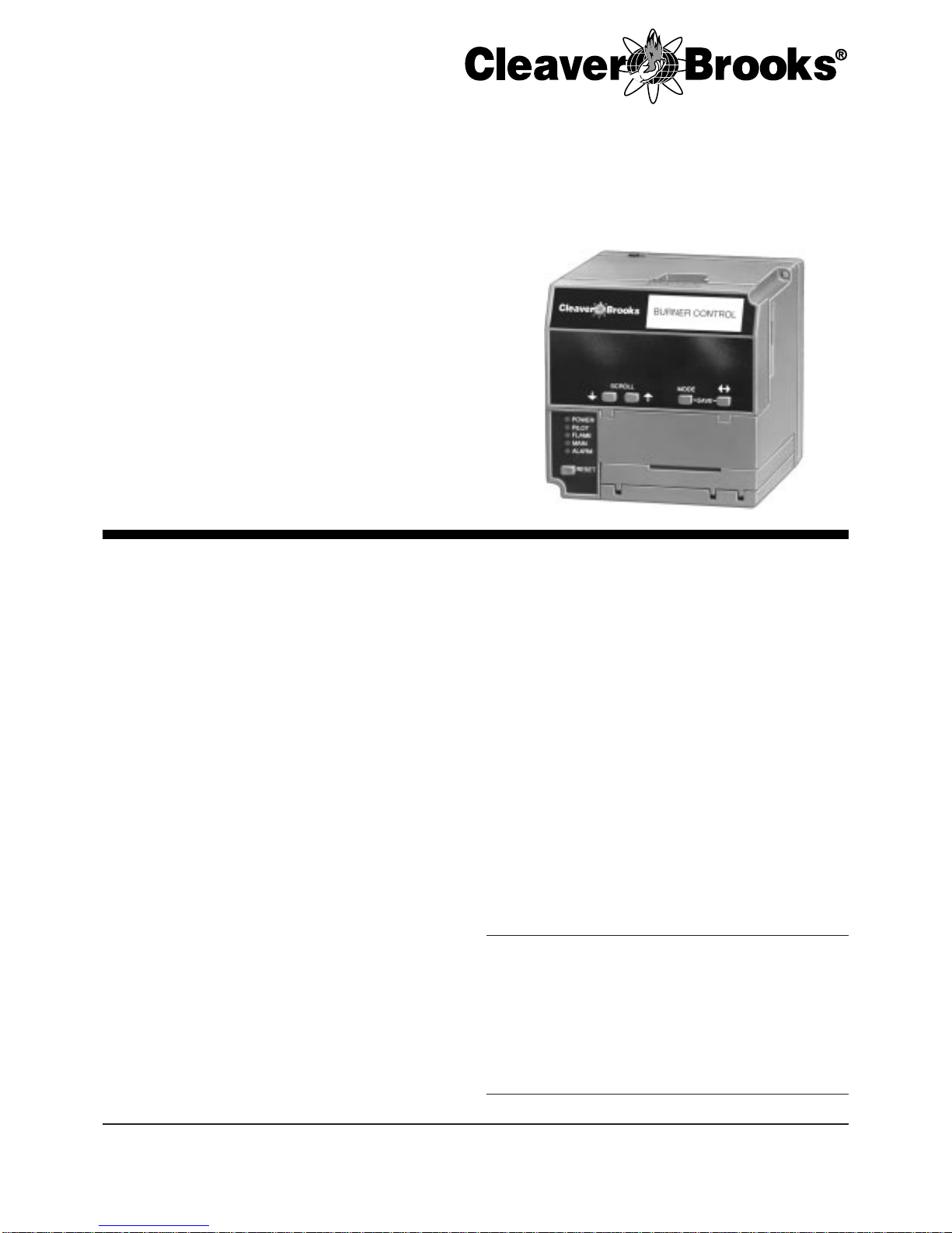
The Cleaver-Brooks CB780/CB784 is a microprocessor
based integrated burner control for automatically fired
gas, oil, or combination fuel single burner applications. The
CB780 consists of a Relay Module and Keyboard Display
Module. The CB784 consists of the Relay Module only. The
Keyboard Display Module is optional with the CB784. Subbase, Amplifier, and Purge Card are r e quired to complete the
system. Options include Personal Computer Interface, Control
Bus, Remote Display Mounting, First-Out Expanded Annunciator and Combustion System Managment software.
The CB780/CB784 is programmed to provide a level of
safety, functional capability and features beyond the capacity
of conventional controls.
Functions provided by the CB780/CB784 include automatic burner sequencing, flame supervision, system status
indication, system or self-diagnostics and troubleshooting
.
■ Safety features:
—Interlock check.
—Closed loop logic test.
—Dynamic Auto-Check.
—Dynamic input check.
—Dynamic safety relay test.
—Dynamic self-check logic.
—Expanded safe-start check.
—High Fire Purge Switch test.
—Internal hardware status monitoring.
—Low Fire Start Switch test.
—Tamper resistant timing and logic.
■ Access for external electrical voltage checks.
■ Application flexibility.
■ Communication interface capability.
■ Dependable, long-term operation provided by microcom-
puter technology.
■ First-out annunciation and system diagnostics provided by
a 2 row by 20 column Vacuum Fluorescent Display (VFD)
located on the Keyboard Display Module.
■ First-out expanded annunciation with 26 Light Emitting
Diodes (LEDs) for limits and interlocks (optional).
■ Five sequence information Light Emitting Diodes (LEDs).
■ Five function Run/Test Switch.
■ Interchangeable plug-in flame amplifiers.
■ Local or remote annunciation of operation and fault
information.
■ Nonvolatile memory for retaining history files and sequenc-
ing status after loss of power.
■ Remote reset (optional).
■ Report generation (optional).
■ Burner controller data:
—Sequence status.
—Sequence time.
—Hold status.
—Lockout/alarm status.
—Flame signal strength.
—Expanded annunciator status.
—Total cycles of operation.
—Total hours of operation.
—Fault history of six most recent faults:
• Cycles of operation at time of fault.
• Expanded annunciator data at time of fault.
• Fault message and code.
• Hours of operation at time of fault.
• Sequence status at time of fault.
• Sequence time at time of fault.
—Diagnostic information:
• Device type.
• Flame amplifier type.
• Flame failure response time.
• Manufacturing code.
• On/Off status of all digital inputs and outputs.
• Selected prepurge time.
• Software revision and version of CB780/CB784 and
Keyboard Display Module.
• Status of configuration jumpers.
• Status of Run/Test Switch.
CONTENTS
Specifications ............................................................... 2
Principle Technical Features ...................................... 6
Safety Provisions ......................................................... 7
Installation ................................................................... 9
Wiring ........................................................................ 11
Assembly .................................................................... 15
Operation ................................................................... 18
Static Checkout .......................................................... 25
Checkout .................................................................... 27
Troubleshooting ......................................................... 34
750-166 1-1
Page 6
CB780/CB784
SPECIFICATIONS
Specif ications
ELECTRICAL RATINGS, see Table 1:
Voltage and Frequency: 120 Vac (+10/-15%), 50 or
60 Hz (+/- 10%)5.
Keyboard Display Module: 13 Vdc peak full wave
rectified (+20/-15%).
Power Dissipation:
CB780/CB784: 10W maximum.
Display Module: 3W maximum.
Maximum Total Connected Load: 2000 VA.
Fusing: Total Connected Load: 20A maximum, type
FRN or equivalent.
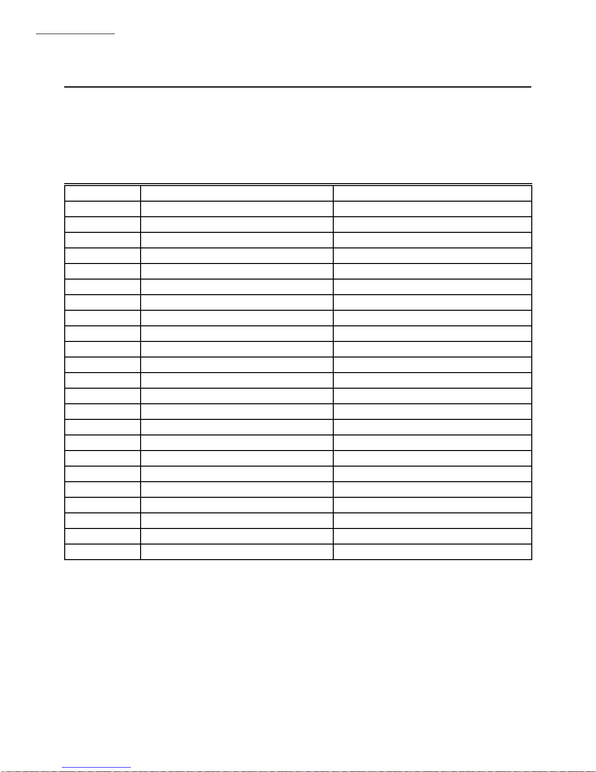
TABLE 1—TERMINAL RATINGS.
Terminal No. Description Ratings
G Flame Sensor Ground
Earth G Earth Ground
1
1
L2(N) Line Voltage Common
3 Alarm 120 Vac, 1A pilot duty.
4 Line Voltage Supply (L1) 120 Vac (+10/-15%), 50 or 60 Hz (±10%).
2,5
5 Burner Motor 120 Vac, 9.8AFL, 58.8ALR (inrush).
6 Burner Controller and Limits 120 Vac, 1 mA.
7 Lockout/Running Interlock 120 Vac, 9A.
8 Pilot Valve/Ignition 120 Vac, 4.5A ignition and 50VA pilot duty.
9 Main Fuel Valve 120 Vac, 2A pilot duty.
10 Ignition 120 Vac, 4.5A Ignition.
4
3
3
F(11) Flame Sensor 60 to 220 Vac, current limited.
12 Firing Rate High Fire 120 Vac, 75 VA pilot duty.
13 Firing Rate Common 120 Vac, 75 VA pilot duty.
14 Firing Rate Low Fire 120 Vac, 75 VA pilot duty.
15 Firing Rate Modulate 120 Vac, 75 VA pilot duty.
16 Unused
17 Unused
18 Low Fire Switch Input 120 Vac, 1 mA.
19 High Fire Switch Input 120 Vac, 1 mA.
20 Preignition Interlock Input 120 Vac, 1 mA.
21 Interrupted/Pilot Valve/First Stage Oil Valve 120 Vac, 2A pilot duty.
22 Shutter 120 Vac, 0.5A.
1
The CB780/CB784 must have an earth ground providing a connection between the subbase and the control panel or the equipment.
The earth ground wire must be capable of conducting the current to blow the 20A fuse (or breaker) in event of an internal short circuit.
The CB780/CB784 needs a low impedance ground connection to the equipment frame which, in turn, needs a low impedance
connection to earth ground. For a ground path to be low impedance at RF frequencies, the connection must be made by minimum
length conductors having maximum surface areas. Wide straps or brackets are preferred rather than leadwires. Be careful to ensure
that mechanically tightened joints along the ground path, such as pipe or conduit threads or surfaces held together with fasteners, are
free of nonconductive coatings and are protected against mating surface corrosion.
2
2000 VA maximum connected load to CB780/CB784 Assembly.
3
Can also be 120 Vac, 1A pilot duty.
4
Can also be 65 VA pilot duty with motorized valve, 1150 VA inrush, 460 VA open, 250 VA hold.
5
Operating frequency chosen by CB780/CB784 selection.
1-2 750-166
Page 7

CB780/CB784
SPECIFICATIONS
ENVIRONMENTAL RATINGS:
Ambient Temperature:
Operating: -40°F to 140°F.
WEIGHT:
CB780/CB784: 1 pound 10 ounces, unpacked.
Keyboard Display Module: 4 ounces, unpacked.
Storage: -40°F to 150°F.
Humidity: 85% RH continuous, noncondensing.
Vibration: 0.5G environment.
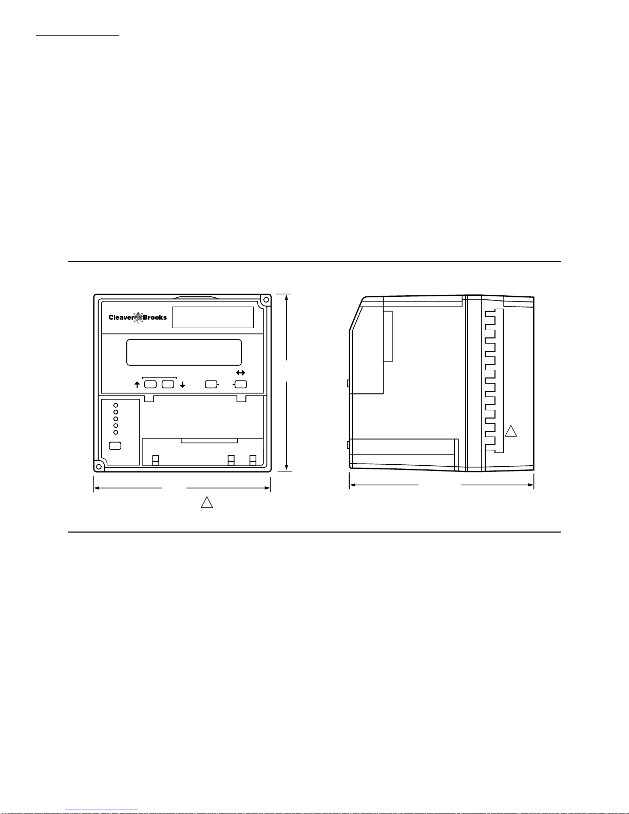
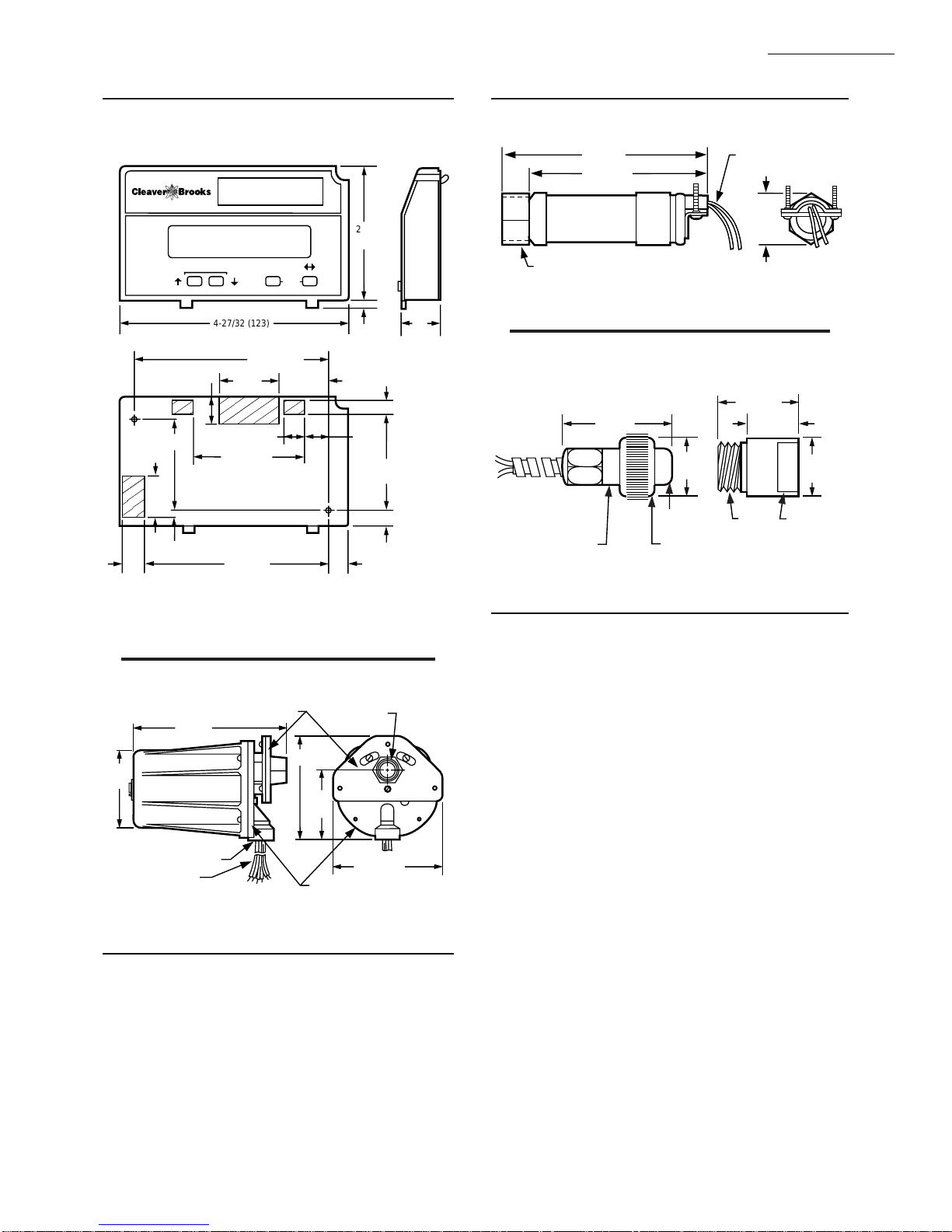
DIMENSIONS: Refer to Figs. 1 and -2.
IMPORTANT: Flame Detection System available for use
with CB780/CB784. To select your Plug-in Flame
Signal Amplifier and matching Flame Detector, see
Table 2.
TABLE 2—FLAME DETECTION SYSTEMS (FIGS. 3, 4, 5).
Plug-In Flame Amplifiers Applicable Flame Detectors
Flame
Failure
Part
Type Color Self-Checking
Number
Infrared Red No 833-2722 3 sec. Gas, oil,
Dynamic AMPLI-
Dynamic Auto-Check
CHECK™
833-2723
Response
Time Fuel Type
coal
c
Gas, oil,
coal
Infrared
(Lead Sulfide)
Infrared
(Lead Sulfide)
Part
Number
817-1742
817-1742
Ultraviolet Purple No 833-2724 Gas, oil Ultraviolet 817-1743
Ultraviolet
Self-Check
Green Dynamic Self-
Check
833-2741
b
Gas, oil,
coal
Ultraviolet
(Purple
817-1121
Peeper)
a
The 817-1743 Flame Detector should be used only on burners that cycle on-off at least once every twenty-four hours. Appliances with
burners that remain on for twenty-four hours continuously or longer should use the 817-1121 Flame Detector with the 833-2741 Amplifier
as the ultraviolet flame detection system.
b
Circuitry tests all electronic components in the flame detection system (amplifier and detector) 12 times a minute during burner operation
and shuts down the burner if the detection system fails.
c
Circuitry tests the flame signal amplifier 12 times a minute during burner operation and shuts down the burner if the amplifier fails.
a
Firing
Rate
2
Energy
Saving
No FM/IRI
Approval
Code
Modulating
TABLE 3—SEQUENCE TIMING FOR NORMAL OPERATION.
Flame
Establishing
Period
Device Initiate Standby Purge Pilot Main Run
CB 780/
CB 784
* STANDBY and RUN can be an infinite time period.
** PURGE will be determined by which purge card is selected.
1
The MFEP will be determined by which terminal is used, see Figs. 7 and 18.
2
The operating sequence of the CB780 and CB784 Relay Modules are identical. The only difference between the Relay
10 sec * ** 4 or
10 sec
10 or
15 sec
* 15 sec Preignition,
1
Post
Purge Interlock
Timing Circuits Circuit Prepurge Bodies
Lockout,
High and
Low Fire
4-wire
modulating
Modules is that the Keyboard Display Module is standard with the CB780 and optional with the CB784.
APPROVAL BODIES:
Underwriters Laboratories Inc. listed, File No. MP268,
Guide No. MCCZ.
Canadian Standards Association certified, LR9S329-3.
Factory Mutual approved, Report No. JI1V9A0.AF.
IRI acceptable.
Federal Communications Commission, Part 15, Class B—
Emissions.
750-166 1-3
Page 8
CCB780/CB784
SPECIFICATIONS
MOUNTING: 833-2725 for panel mount.
REQUIRED COMPONENTS:
CB780: 120 Vac/60 Hz, 833-2718.
CB780: 120 Vac/50 Hz, 833-2719.
CB784: 120 Vac/60 Hz, 833-2720.
CB784: 120 Vac/ 50 Hz, 833-2721
Plug-in Flame Signal Amplifier, see Table 2.
Plug-in Purge Timer Cards: selectable:
833-2730 30 sec.
833-2731 60 sec.
833-2732 90 sec.
833-2733 2-1/2 min.
ACCESSORIES:
Optional:
Control Bus—part no. 833-2729. Provides
communication and remote reset capabilities on
CB784; remote display capabilities on CB780
and CB784.
CB783 Expanded Annunciator—part no. 833-2726.
Keyboard Display Module—part no. 833-2727.
(Standard on CB780; optional on CB784.)
Remote Mounting Kit for the Keyboard Display,
NEMA 4—part no. 833-2740.
Tester—part no. 626-5050.
NOTE: The CB780 and CB784 are identical except for the
Keyboard Display Module which is standard with the
CB780 and optional with the CB784.
Fig. 1—Mounting dimensions of CB780/CB784 Relay Module and 833-2725 Subbase, in inches (mm)
BURNER CONTROL
SCROLL MODE
SAVE
5
(127)
POWER
PILOT
FLAME
MAIN
ALARM
RESET
5 (127)
1
REMOVE ONLY FOR TERMINAL TEST ACCESS.
1
5-1/4 (133)
M7399
1-4 750-166
Page 9
CB780/CB784
,
,
SPECIFICATIONS
Fig. 2—Mounting dimensions of Keyboard
Display Module, in inches (mm).
BURNER CONTROL
2-3/4
(69)
15/
32
(12)
1-15/16
(49)
29/32
(23)
SCROLL MODE
19/32
(15)
5/32 (4)
4-27/32 (123)
1-1/4
(32)
7/16 (11)
2-5/16 (58)
3-7/8 (99)
SAVE
4-3/32 (104)
1-1/32
(26)
13/
32
(11)
5/32
(4)
1/2
(13)
5/16
(8)
2-1/32
(52)
5/15
(8)
29/32
(23)
M7405
Fig. 4—Ultraviolet detector.
4 (102)
3-1/2 (89)
COLLAR WITH 1/2-14 NPSM
INTERNAL THREADS
817-1743
Fig. 5—Infrared detector.
2-3/4
(70)
2 LEADS IN A
48 INCH [1.2 METER]
FLEXIBLE CONDUIT
BUSHING WITH
MAGNIFYING LENS
COLLAR, 3/4-14 NPSM
INTERNAL THREADS
817-1742
1-1/4
(32)
APERTURE
6 FOOT (1.83 METER)
LEADWIRES (2)
1-1/16
(27)
HEAT BLOCKCELL MOUNT
1-5/8 (41)
1-1/16 (27)
1-1/4
3/4-14
NPSM
3/4-14 NPSM
INTERNAL
THREADS
M7419
(32)
M1982A
833-2727
(Standard with CB780, optional with CB784)
Fig. 3—Ultraviolet Self-Check detector.
3-3/4
(95)
7-7/32
(183)
1/2–14 NPSM
LEADWIRES
MOUNTING FLANGE
817-1121
5-1/8 (130)
3-7/16
(87)
FACEPLATE
3/4–14 NPT
5-1/4 (133)
M1962A
750-166 1-5
Page 10

CB780/CB784
PRINCIPAL TECHNICAL FEATURES
Principal T echnical Features
The CB780/CB784 provides all customary flame safeguard functions while providing significant advancements in
the areas of safety, annunciation and system diagnostics.
SAFETY SHUTDOWN (LOCKOUT) OCCURS IF:
1. INITIATE Period
a. Purge card is not installed or removed.
b. Purge card is bad.
c. Configuration jumpers were changed (after
200 hours).
d. AC line power errors, see Operation.
e. Four minute INITIATE period is exceeded.
2. STANDBY Period
a. Flame signal is present after 40 seconds.
b. Preignition Interlock is open an accumulative time
of 30 seconds.
c. Interlock check feature is enabled and the Inter-
lock String (including the airflow switch) is closed
for 120 seconds with controller closed.
d. Ignition/pilot valve/intermittent pilot valve termi-
nal is energized.
e. Main valve terminal is energized.
f. Internal system fault.
g. Purge card is not installed or removed.
h. Purge card is bad.
3. PREPURGE Period
a. Preignition Interlock opens anytime during
PREPURGE.
b. Flame signal detected after first ten seconds during
PREPURGE.
c. High Fire Switch fails to close within four minutes,
fifteen seconds after firing rate motor is commanded
to drive to high fire position at start of PREPURGE.
d. Low Fire Switch fails to close within four minutes,
fifteen seconds after firing rate motor is commanded
to drive to low fire position at end of PREPURGE.
e. Lockout Interlock does not close within 10 seconds.
f. Lockout Interlock opens during PREPURGE.
g. Ignition/pilot valve/intermittent pilot valve termi-
nal is energized.
h. Main valve terminal is energized.
i. Internal system fault.
j. Purge card is removed.
k. Purge card is bad.
4. PILOT FLAME ESTABLISHING Period (PFEP)
a. Low Fire Switch opens.
b. Lockout Interlock opens.
c. Ignition/pilot valve/intermittent pilot valve terminal
is not energized.
d. Early Spark Termination terminal is energized af-
ter five seconds.
e. No flame is present at end of PFEP.
f. Internal system fault.
g. Purge card is removed.
h. Purge card is bad.
5. MAIN FLAME ESTABLISHING Period (MFEP)
a. Low Fire Switch opens.
b. Lockout Interlock opens.
c. Ignition/pilot valve/intermittent pilot valve termi-
nal is not energized.
d. Main valve terminal is not energized.
e. No flame is present at end of MFEP.
f. Internal system fault.
g. Purge card is not installed or removed.
h. Purge card is bad.
6. RUN Period
a. No flame is present.
b. Lockout Interlock opens.
c. Main valve terminal is not energized.
d. Internal system fault.
e. Purge card is not installed or removed.
f. Purge card is bad.
7. POSTPURGE Period
a. Preignition Interlock does not close within five sec-
onds or opens after five-second time period.
b. Ignition/pilot valve/intermittent pilot valve termi-
nal is energized.
c. Main valve terminal is energized.
d. Internal system fault.
e. Purge card is removed.
f. Purge card is bad.
1-6 750-166
Page 11

CB780/CB784
SAFETY PROVISIONS
Safety Pro visions
INTERNAL HARDWARE STATUS MONITORING
The CB780/CB784 checks the purge card for correct
parity to prevent purge timing shifts and circuitry failures. It
also analyzes the integrity of the configuration jumpers and
internal hardware. The POWER LED blinks every four
seconds, signifying an internal hardware check.
CLOSED LOOP LOGIC TEST
The test verifies the integrity of all safety critical loads,
terminals 8, 9, 10 and 21. If the loads are not energized
properly; i.e., the main valve terminal is powered during
PREPURGE, the CB780/CB784 will lockout on safety shutdown. The CB780/CB784 must react to input changes but
avoid the occurrence of nuisance shutdown events. Signal
conditioning is applied to line voltage inputs to verify proper
operation in the presence of normal electrical line noise such
as transient high voltage spikes or short periods of line
dropout. Signal conditioning is tolerant of synchronous noise
(line noise events that occur at the same time during each line
cycle).
DYNAMIC AUTO-CHECK
Dynamic Auto-Check circuitry tests the flame signal
amplifier during burner operation and shuts down the CB780/
CB784 if the flame amplifier fails.
DYNAMIC FLAME AMPLIFIER AND SHUTTER
CHECK
Self-checking circuitry tests all electronic components in
the flame detection system and amplifier 10 to 12 times per
minute and shuts down the CB780/CB784 if the detection
system fails.
DYNAMIC INPUT CHECK
All system input circuits are examined to verify that the
CB780/CB784 is capable of recognizing the true status of
external controls, limits and interlocks. If any input fails this
test, a safety shutdown occurs and the fault is annunciated.
DYNAMIC SAFETY RELAY TEST
Checks the ability of the dynamic safety relay contacts to
open and close. It also verifies that the safety critical loads,
terminals 8, 9, 10 and 21, can be de-energized, as required, by
the Dynamic Self-Check logic.
DYNAMIC SELF-CHECK SAFETY CIRCUIT
The microcomputer tests itself and related hardware
while at the same time the safety relay system tests the microcomputer operation. If a microcomputer or safety relay
failure occurs and does not allow proper execution of the
self-check routine, safety shutdown will occur and all safety
critical loads will be de-energized.
EXPANDED SAFE-START CHECK
The conventional safe-start check, which prevents burner
start-up if flame is indicated at start-up, is expanded to
include a flame signal check during STANDBY, a preignition interlock check, an interlock check, and a safety critical
load check.
HIGH FIRE PURGE AND LOW FIRE START
SWITCH TESTS
High Fire Purge Switch Test examines the Purge Position Interlock Switch at the moment the firing rate motor is
commanded to the high fire position. If the switch is bypassed, welded or otherwise closed prematurely, the system
will automatically add 30 seconds to allow additional drive
time for the firing rate motor to reach or near the open
position before starting the purge timing; otherwise, purge
timing starts when the High Fire Switch is closed. This
switch will also cause a hold (four minutes, fifteen seconds)
condition when the switch is open before purge or opens
during purge. The CB780/CB784 will lockout and annunciate an alarm if the switch fails to close within the hold time
period.
Low Fire Start Switch Test examines the Low Fire Start
Switch at the moment PREPURGE is completed. If the
switch is bypassed, welded or otherwise prematurely closed,
the system automatically adds 30 seconds to allow the firing
rate motor additional time to reach or near the low fire start
position before ignition trials; otherwise, ignition trials start
after the Low Fire Switch closes. The test also is used to prove
that the firing rate motor is at low fire position throughout
the ignition trial period. This switch will also cause a hold
(four minutes, fifteen seconds) condition if the switch opens
after purging is complete. The CB780/CB784 will lockout
and annunciate an alarm if the switch fails to close within the
hold time period.
750-166 1-7
Page 12

CB780/CB784
SAFETY PROVISIONS
MANDATORY PURGE
If lockout occurs after the initiation of ignition trials,
(or at anytime during a sequence when the fuel valves may
have been energized), a mandatory POSTPURGE period is
imposed.
OFF CYCLE (STANDBY OR PREPURGE) FLAME
SIGNAL CHECK
The flame detection subsystem (flame detector and amplifier) is monitored during STANDBY. If a flame simulating condition or an actual flame exists, a system hold occurs
and start-up is prevented. If the flame signal exists at any
time after the first 40 seconds of STANDBY, a safety shutdown will occur and be annunciated. A shutter-check amplifier and self-checking detector are energized for the first
40 seconds during STANDBY and the last two seconds
before exiting STANDBY. If a flame exists, a safety shutdown occurs. An Auto-Check Amplifier is energized continually through STANDBY and PREPURGE to detect any
possibility of a runaway detector or a flame. If either situation happens, a safety shutdown occurs. A standard amplifier
is energized continually through STANDBY and
PREPURGE. If either situation happens, a safety shutdown
occurs.
PREIGNITION OUTPUT CIRCUIT CHECK
At the end of PREPURGE, the Dynamic Safety Relay
operation is checked. Also, all safety critical loads, terminals
8, 9, 10 and 21 are checked to verify the terminals are not
powered. If the Dynamic Safety Relay operation is faulty, or
if any of the safety critical loads are powered, safety shutdown occurs and is annunciated.
TAMPER RESISTANT TIMING AND LOGIC
Safety and logic timings are inaccessible and cannot be
altered or defeated.
VERIFIED SPARK TERMINATION
The ignition terminal is monitored to verify early spark
termination (five seconds ignition and pilot and five seconds
pilot only).
FIRST-OUT ANNUNCIATION AND
SELF-DIAGNOSTICS
Sequence Status Lights (LEDs) provide positive visual
indication of the program sequence: POWER, PILOT,
FLAME, MAIN and ALARM. The green POWER LED
blinks every four seconds to signify the CB780/CB784
hardware is running correctly.
Multi-function Keyboard Display Module (standard with
CB780, optional with CB784) shows elapsed time during
PREPURGE, PILOT IGN, MAIN IGN, and POSTPURGE.
As an additional troubleshooting aid, it provides sequence
timing, diagnostic information, historical information and
expanded annunciator information when a safety shutdown
or hold or normal operation occurs.
First-out Annunciation reports the cause of a safety shutdown or identifies the cause of a failure to start or continue
the burner control sequence with an English text and numbered code via the Keyboard Display Module. It monitors all
field input circuits, including the Flame Signal Amplifier
and Firing Rate Position Switches. The system distinguishes
118 modes of failure and detects and annunciates difficultto-find intermittent failures.
Self-Diagnostics adds to the First-out Annunciation by
allowing the CB780/CB784 to distinguish between field
(external device) and internal (system related) problems.
Faults associated within the flame detection subsystem,
CB780/CB784 or plug-in Purge Card, are isolated and reported by the Keyboard Display Module. See the Diagnostics and Troubleshooting section of the CB780/CB784 Operation and Maintenance Manual, Manual Number 750-166.
INTERLOCK REQUIREMENTS
The following interlock inputs are provided:
Low Fire Interlock
This interlock verifies the firing rate motor is in the low
fire position before and during ignition trials.
High Fire Interlock
This interlock verifies the firing rate motor is in the high
fire position prior to and during PREPURGE.
Lockout Interlock
This interlock (ILK) input signifies a Lockout Interlock.
If the Lockout Interlock is open for more than ten seconds
into PREPURGE, the CB780/CB784 will lockout. After
entering PREPURGE, if the Lockout Interlock opens during
the first ten seconds, the purge timer will be reset. This
provides a continuous PURGE to occur without interruption
before the Pilot Flame Establishing Period. If a Lockout
Interlock opens anytime after ten seconds into PURGE,
during the Ignition Trials or Run, it causes a lockout.
A typical Lockout Interlock string contains an airflow
switch (see Fig. 7). The Interlock Check is a site configurable option (see Table 7). If this feature is enabled, the
CB780/CB784 will lockout after 120 seconds whenever
control terminal 6 is energized, and the Lockout Interlock
string (including airflow switch) is closed during STANDBY.
Preignition Interlock
The Preignition Interlock input is typically connected to
proof-of-closure switches for fuel valve(s). The Preignition
Interlock must be energized throughout PREPURGE. If the
Preignition Interlock opens during STANDBY, it causes a
hold (30 seconds). The CB780/CB784 will lockout if the
interlock does not close within 30 seconds during STANDBY.
If the Preignition Interlock opens during PREPURGE, it
will lockout. If the Preignition Interlock is open after five seconds into POSTPURGE, the CB780/CB784 will lockout.
The Preignition Interlock is ignored during the ignition trials
state and during RUN.
1-8 750-166
Page 13
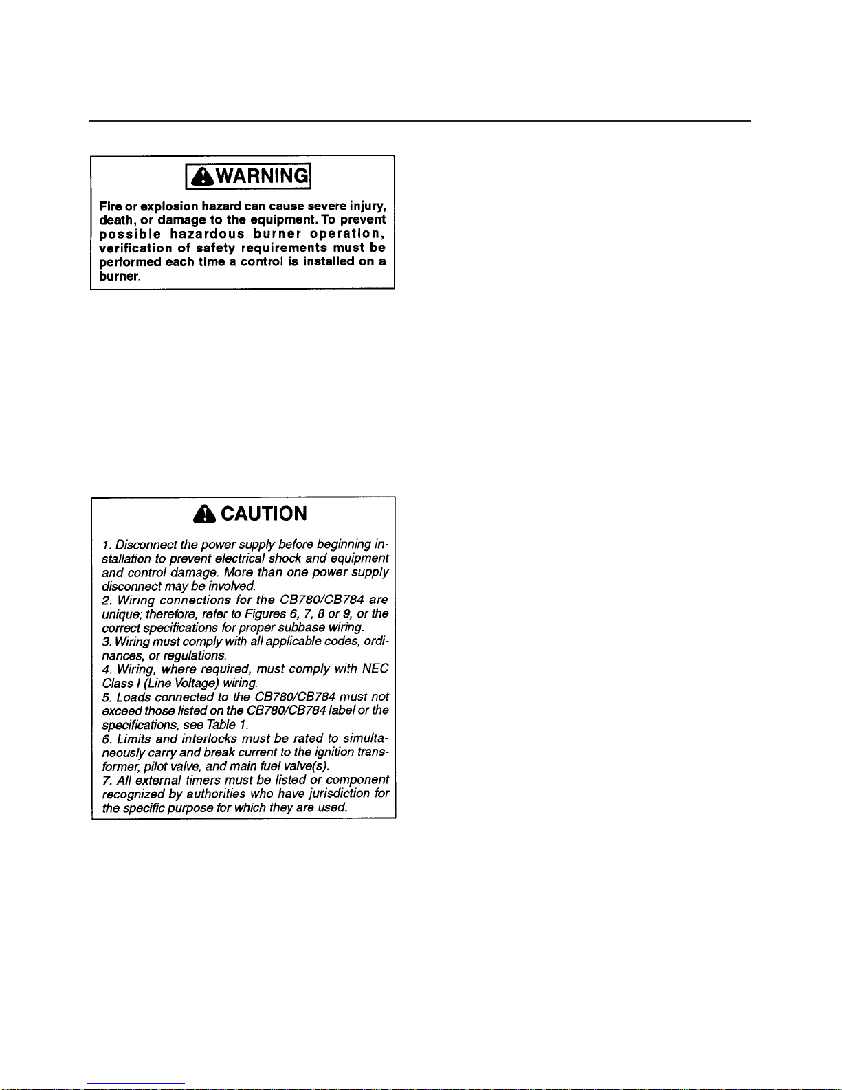
WARNING
FIRE OR EXPLOSION HAZARD
CAN CAUSE PROPERTY DAMAGE,
SEVERE INJURY, OR DEATH.
To prevent possible hazardous burner operation,
verification of safety requirememts must be per-
formed each time a control is installed on a burner.
WHEN INSTALLING THIS PRODUCT…
1. Read these instructions carefully. Failure to follow
them could damage the product or cause a hazardous
condition.
2. Check the ratings given in the instructions and
marked on the product to make sure the product is suitable
for the application.
3. Installer must be a trained, experienced, flame safeguard service technician.
4. After installation is complete, check out the product
operation as provided in these instructions.
CA UTION
1. Disconnect the power supply before beginning
installation to prevent electrical shock, equip-
ment and control damage. More than one power
supply disconnect may be involved.
2. Wiring connections for the CB780/CB784 are
unique; therefore, refer to Figs. 6, 7, 8 o r 9 or
the correct Specifications for proper subbase
wiring.
3. Wiring must comply with all applicable codes,
ordinances and regulations.
4. Wiring, where required, must comply with NEC
Class 1 (Line Voltage) wiring.
5. Loads connected to the CB780/CB784 must not
exceed those listed on the CB780/CB784 label
or the Specifications, see Table 1.
6. Limits and interlocks must be rated to simulta-
neously carry and break current to the ignition
transformer, pilot valve, and main fuel valve(s).
7. All external timers must be listed or component
recognized by authorities who have jurisdiction
for the specific purpose for which they are used.
IMPORTANT:
1. For on-off gas-fired systems, some authorities who
have jurisdiction prohibit the wiring of any limit or
operating contacts in series between the flame safeguard control and the main fuel valve(s).
2. Two Flame Detectors can be connected in parallel with
the exception of Infrared Flame Detector (817-1742).
CB780/CB784
INSTALLATION
Installation
3. This equipment generates, uses and can radiate radio
frequency energy and, if not installed and used in
accordance with the instructions, may cause interference to radio communications. It has been tested and
found to comply with the limits for a Class B computing device of Part 15 of FCC rules which are designed
to provide reasonable protection against such interference when operated in a commercial environment.
Operation of this equipment in a residential area may
cause interference; in which case, the users at their
own expense may be required to take whatever measures are required to correct this interference.
4. This digital apparatus does not exceed the Class B
limits for radio noise for digital apparatus set out in
the Radio Interference Regulations of the Canadian
Department of Communications.
HUMIDITY
Install the CB780/CB784 where the relative humidity
never reaches the saturation point. The CB780/CB784 is
designed to operate in a maximum 85% RH continuous,
noncondensing, moisture environment. Condensing moisture may cause a safety shutdown.
VIBRATION
Do not install the CB780/CB784 where it could be subjected to vibration in excess of 0.5G continuous maximum
vibration.
WEATHER
The CB780/CB784 is not designed to be weather tight. If
installed outdoors, the CB780/CB784 must be protected by
an approved weather-tight enclosure.
MOUNTING WIRING SUBBASE
NOTE: For installation dimensions, see Fig. 1.
1. Mount the subbase in any position except horizontally
with the bifurcated contacts pointing down. The standard
vertical position is recommended. Any other position decreases the maximum ambient temperature rating.
2. The 833-2725 Wiring Subbase can be mounted directly in the control cabinet. Be sure to allow adequate clearance for servicing, installation, access or removal of the
CB780/CB784, Expanded Annunciator, Keyboard Display Module, flame amplifier, flame amplifier signal voltage
probes, Run/Test Switch, electrical signal voltage probes
and electrical field connections.
3. For surface mounting, use the back of the subbase as a
template to mark the four screw locations. Drill the pilot
holes.
4. Securely mount the subbase using four no. 6 screws.
750-166 1-9
Page 14

CB780/CB784
INSTALLATION
Fig. 6—Internal block diagram of the CB780/CB784 (see Figs.7,8,9, or 10 for detailed wiring instructions).
4
RESET
PUSHBUTTON
STATUS LEDs
RUN/TEST
SWITCH
CONFIGURATION
JUMPERS
MICROCOMPUTER
SAFETY RELAY
CIRCUIT
RELAY
DRIVE
CIRCUIT
L1
(HOT) L2
1
120 Vac
2K
3K
4K
5K
6K
7K
8K
9K
1K
POWER SUPPLY
PLUG-IN PURGE
TIMER CARD
FLAME SIGNAL
PLUG-IN
FLAME
AMPLIFIER
TEST
L2
TEST
JACK
F
G
22
RELAY
STATUS
FEEDBACK
AND LINE
VOLTAGE
INPUTS
CONTROL
POWER
20
PRE-IGNITION
INTERLOCK
LIMITS CONTROLLER
6K1
3K1
KEYBOARD
DDL
DISPLAY MODULE
RS485
DDL
COMMUNICATIONS
PROVIDE DISCONNECT MEANS AND OVERLOAD PROTECTION AS REQUIRED.
1
1
2
LOCKOUT
INTERLOCK
6
LOW FIRE SWITCH
18
HIGH FIRE SWITCH
19
REMOTE
3
RESET
1K1 2K1 5K1
7
4K1
7K1
2K2
HIGH FIRE
8K1
COMMON
8K2
MODULATE
9K2
LOW FIRE
2
9K1
12
13
15
14
2 REMOTE RESET MUST BE MOUNTED WITHIN SIGHT OF THE BOILER CONTROL PANEL.
10
8
21
9
5
3
INDICATES FEEDBACK SENSING
TO RELAY STATUS FEEDBACK
AND LINE VOLT INPUTS
FIELD WIRING
INTERNAL WIRING
IGNITION
PILOT
PILOT/V2
MAIN VALVE
BLOWER
ALARM
M7420
1-10 750-166
Page 15

CB780/CB784
Wiring
WIRING
1. a. For proper subbase wiring, refer to Fig. 7.
b. For proper remote wiring of the Keyboard Dis-
play Module, refer to Fig. 8, 9 or 10 or to the
Specifications for the Keyboard Display Module,
Communication Interface Base Unit or Control
Bus.
2. Disconnect the power supply from the main discon-
nect before beginning installation to prevent electrical
shock and equipment damage. More than one disconnect
may be involved.
3. All wiring must comply with all applicable electrical
codes, ordinances and regulations. Wiring, where required,
must comply with NEC, Class 1 (Line Voltage) wiring.
4. Recommended wire size and type:
a. All Line Voltage terminals use no. 14 or 16 cop-
per conductor (90°C or higher) 600 volt insulation wire (wire size must be coordinated with fuse
protection). For high temperature installations,
use wire selected for a temperature rating above
the maximum operating temperature. All leadwires
should be moisture resistant.
b. Keyboard Display Module—For communica-
tions purposes, use an unshielded 22 AWG 2-wire
twisted cable and one wire for ground if the
leadwire run and noise conditions permit; however, some installations may need up to five wires,
three for communications and two for remote reset
(in either a single cable or separate cables for communications or remote reset) or use Belden 8771
shielded cable or equivalent. The Keyboard Display Module, Control Bus (for remote mounting or
communications) or Communication Interface
ControlBus Module must be wired in a daisy chain
configuration, (1(a)-1(a), 2(b)-2(b), 3(c)-3(c)). The
order of interconnection of all the devices listed
above is not important. Be aware that modules on
the closest and farthest end of the daisy chain
configuration string require a 120 ohm (1/4 watt
minimum) resistor termination across terminals
1 and 2 of the electrical connectors, for connections over 100 feet, see Fig. 8, 9 and 10.
c. Control Bus—For communications purposes,
use an unshielded 22 AWG 2-wire twisted cable
if the leadwire run and noise conditions permit;
however, some installations may need up to five
wires, three for communications and two for remote reset (in either a single cable or separate
cables) or use a Belden 8771 shielded cable or
equivalent. The Keyboard Display Module, Control Bus (for remote mounting or communications)
or Communication Interface ControlBus Module
must be wired in a daisy chain configuration,
(1(a)-1(a), 2(b)-2(b), 3(c)-3(c)). The order of interconnection of all the devices listed above is not
important. Be aware that modules on the closest
and farthest end of the daisy chain configuration
string require a 120 ohm (1/4 watt minimum) resistor termination across terminals 1 and 2 of electrical connectors, for connections over 100 feet, see
Fig. 8, 9 and 10.
d. Remote Reset*—Use no. 22 AWG or greater
twisted pair wire, insulated for low voltage; see
Fig. 8, 9 and 10.
e. Communication Interface ControlBus Module—
For communications purposes, use an unshielded
22 AWG 2-wire twisted cable if the leadwire run
and noise conditions permit or use a Belden 8771
shielded cable or equivalent. The Keyboard
Display Module, Control Bus (for remote mounting or communications) or Communication Interface ControlBus Module must be wired in a daisy
chain configuration, (1(a)-1(a), 2(b)-2(b), 3(c)-3(c)).
The order of interconnection of all the devices
listed above is not important. Be aware that
modules on the closest and farthest end of the
daisy chain configuration string require a 120
ohm (1/4 watt minimum) resistor termination
across terminals 1 and 2 of the electrical connectors, for connections over 100 feet, see Fig. 8, 9
and 10.
f. Use the recommended wire size for the 13 Vdc
full wave rectified transformer power input of
no. 18 AWG wire insulated for voltages and temperatures encountered in the application. Suggested wire types include TTW(60C), THW(75C)
and THHN(90C).
5. Recommended grounding practices:
a. The earth ground provides for a connection be-
tween the subbase and the control panel of the equipment. The earth ground wire must be capable of
conducting the current to blow the 20A fuse (or
breaker) in event of an internal short circuit. The
CB780/CB784 needs a low impedance ground
connection to the equipment frame which, in
turn, needs a low impedance connection to earth
ground. For a ground path to be low impedance
at RF frequencies, the connection must be made
with minimum length conductors that have a
maximum surface area. Wide straps or brackets
are preferred rather than leadwires. Be careful to
ensure that mechanically tightened joints along
the ground path, such as pipe or conduit threads
or surfaces held together with fasteners, are free
of nonconductive coatings and are protected
against corrosion on mating surfaces.
b. Keyboard Display Module,
Comm
unication Interface ControlBus Module—
Control Bus, or
750-166 1-11
*Note: Remote Reset must be mounted within sight
of the boiler control panel.
Page 16

CB780/CB784
WIRING
The shield, if used, should be connected to the
signal ground terminal 3(c) provided as part of the
CB780/CB784 device ControlBus connection.
Connect the shield at both ends to earth ground.
c. CB780/CB784—Each CB780/CB784 will have
an earth ground terminal that must be grounded to
the metal control panel with wire as short as practical. Each ground wire must be capable of carrying
a fault current equal to the rating of the protective fuse (20A). A number 14 copper conductor
is adequate, but wide straps or brackets are preferred rather than leadwires.
6. Recommended wire routing:
a. Flame detector leadwires:
1. Do not run high voltage ignition transformer
wires in the same conduit with the flame detection wiring.
2. Do not route scanner wires in conduit with line
voltage circuits.
3. Enclose scanner wires without armor cable in
metal cable or conduit.
4. Follow directions in flame detector Instructions.
b. Control Bus:
1. Do not run high voltage ignition transformer
wires in the same conduit or close proximity
with the Control Bus wiring.
2. Do not route Control Bus wires in conduit with line
voltage circuits.
c. Keyboard Display Module (VFD): Because the
VFD is powered from a low voltage, energy limited source, it can be mounted outside of a control
panel if it is protected from mechanical damage.
d. Remote Reset:
1. Do not run high voltage ignition transformer
wires in the same conduit with the Remote Reset
wiring.
2. Do not route Remote Reset wires in conduit
with line voltage circuits.
NOTE: A 13 Vdc power supply must be used any time more
than one Keyboard Display Module is used.
7. Maximum wire lengths:
a. CB780/CB784 leadwires—The maximum length
of leadwire is 300 feet to terminal inputs (Control,
Preignition Interlock, Running/Lockout Interlock,
High Fire Switch and Low Fire Switch).
b. Flame Detector leadwires—The maximum flame
sensor leadwire length is limited by the flame
signal strength.
c. Remote Reset leadwires—The maximum length
of wire is 1000 feet to a Remote Reset pushbutton.
d. Control Bus—The maximum Control Bus cable
length depends on the number of system modules
connected, the noise conditions and the cable used.
The maximum length of all interconnecting wire
is 1000 feet.
8. Make sure loads do not exceed the terminal ratings.
Refer to the label on the CB780/CB784 or to the ratings in
Specifications; see Table 1.
9. Check the power supply circuit. The voltage and fre-
quency tolerance must match those of the CB780/CB784. A
separate power supply circuit may be required for the
CB780/CB784. Add the required disconnect means and
overload protection.
10. Check all wiring circuits and complete the Static
Checkout, see Table 8, before installing the CB780/CB784
on the subbase.
11. Install all electrical connectors.
12. Restore power to the panel.
1-12 750-166
Page 17
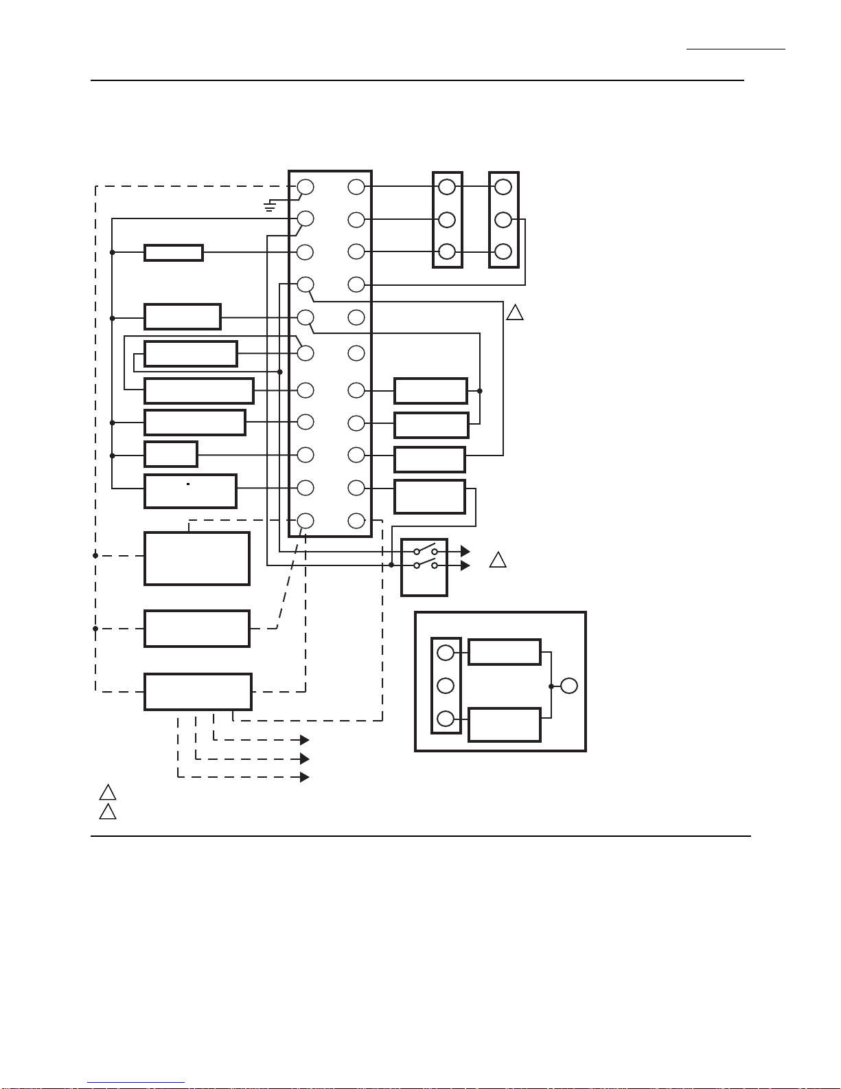
FIG. 7—WIRING CB780/CB784
833-2725
G
12
HIGH FIRE
SERIES 90
FIRING RATE
MOTOR
B
SERIES 90
CONTROLLER
B
CB780/CB784
WIRING
13
14
15
16
17
18
19
20
21
22
COMMON
LOW FIRE
MODULATE
LOW FIRE
START SWITCH
HIGH FIRE
PURGE SWITCH
PREIGNITION
INTERLOCK
15 SEC.
INTERRUPTED
PILOT VALVE
MASTER
SWITCH
R
W
L1
(HOT)
L2
R
W
1
120V ALARM
BURNER MOTOR
(BLOWER)
BURNER
CONTROLLER/LIMITS
LOCKOUT INTERLOCKS
(INC. AIR FLOW SWITCH)
10 SEC. INTERRUPTED
PILOT/IGNITION
MAIN FUEL
VALVE(S)
5 SECOND IGNITION
(EARLY SPARK)t
(EARLY SPARK
(TERMINATION)
TERMINATION)
817-1742
INFRARED
(LEAD SULFIDE)
FLAME DETECTOR
L2
10
3
(L1)
4
5
6
7
8
9
F
OR
WHITE
817-1743
ULTRAVIOLET
FLAME DETECTOR
OR
YELLOW
1
2
817-1121
ULTRAVIOLET
FLAME DETECTOR
120V, 60 Hz POWER SUPPLY. PROVIDE DISCONNECT MEANS AND OVERLOAD PROTECTION AS REQUIRED.
DO NOT WIRE TO ANY UNUSED TERMINALS.
BLUE
BLUE
WHITE
WHITE
BLACK
BLACK
FOR DIRECT SPARK IGNITION (OIL
OR GAS)
IGNITION
10
TRANSFORMER
8
2ND STAGE
9
FUEL VALVE
L2
L1
L2
(OPTIONAL)
2
L2
M7408
750-166 1-13
Page 18
CB780/CB784
L1
(HOT)
L2
1
1
120 OHM
RESISTOR
1
120 OHM
RESISTOR
A
B
A
B
C (GND)
+13 VDC
RESET
C (GND)
+13 VDC
RESET
1
23
4
5
1
23
4
5
MOMENTARY
PUSH BUTTON
SWITCH
833-2727 KEYBOARD DISPLAY MODULE
(MOUNTED ON CB 780/CB 784)
13 VDC
POWER SUPPLY
833-2727 REMOTE KEYBOARD DISPLAY MODULE
THREE WIRE SHIELDED CABLE MAY BE REQUIRED. TWO 120
OHM TERMINATING RESISTORS ARE REQUIRED FOR
CONNECTIONS OVER 100 FEET. CABLE SHIELD MUST BE
TERMINATED TO EARTH GROUND AT BOTH ENDS. IF SHIELDED
CABLE IS NOT USED, TWISTED PAIR WIRE MUST BE USED.
M7409
WIRING
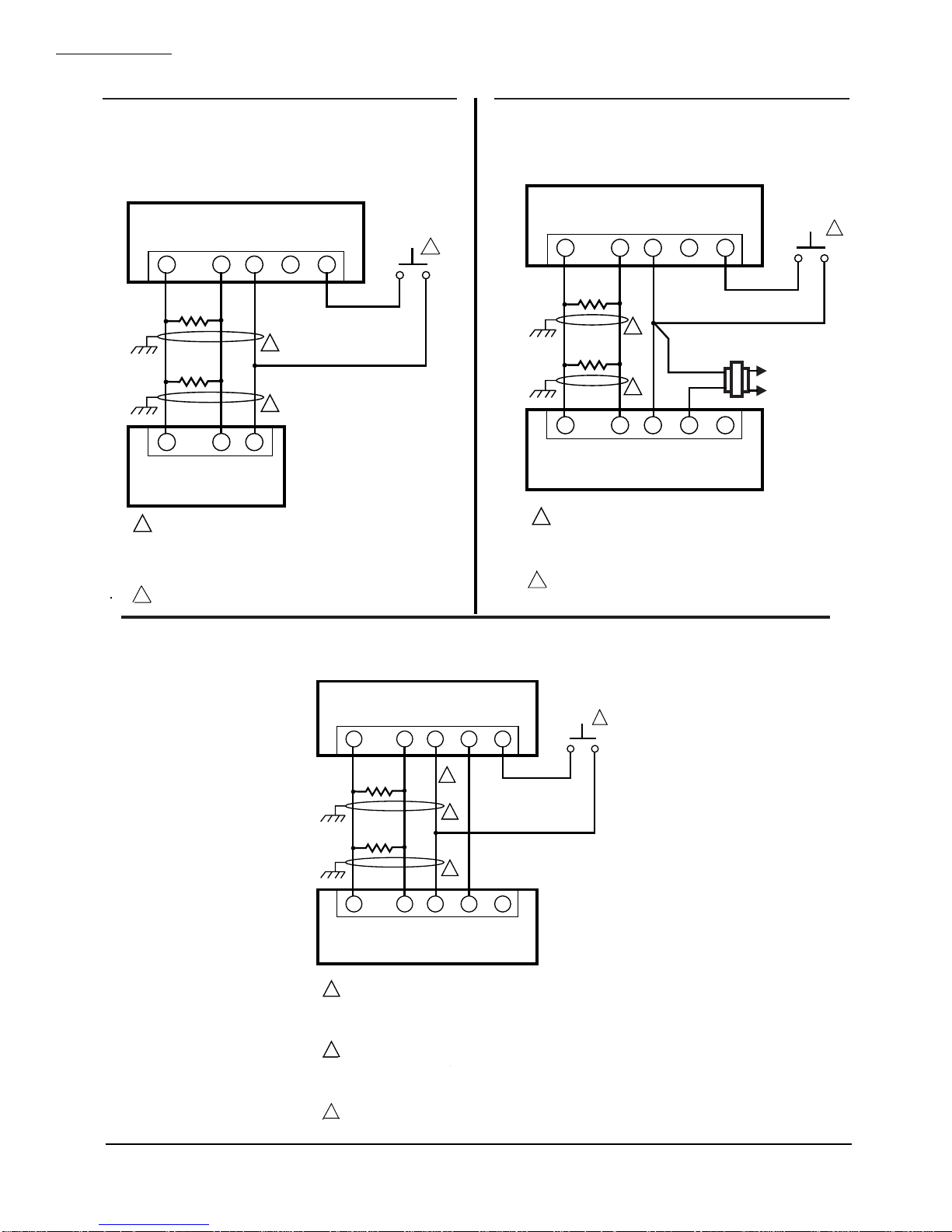
Fig. 8—Wiring the Keyboard Display Module with
Communication Interface ControlBus Module.
833-2727 KEYBOARD DISPLAY MODULE
(MOUNTED ON CB 780/CB 784)
MOMENTARY
PUSH BUTTON
A
1
120 OHM
RESISTOR
120 OHM
RESISTOR
1
A
THREE WIRE SHIELDED CABLE MAY BE REQUIRED. TWO 120
1
OHM TERMINATING RESISTORS ARE REQUIRED FOR
CONNECTIONS OVER 100 FEET (30 METERS). CABLE SHIELD
MUST BE TERMINATED TO EARTH GROUND AT BOTH ENDS.
IF SHIELDED CABLE IS NOT USED, TWISTED PAIR
WIRE MUST BE USED.
2 REMOTE RESET MUST BE MOUNTED WITHIN SIGHT OF
THE BOILER CONTROL PANEL.
B
C (GND)
23
1
1
23
B
C
RESET
+13 VDC
4
5
833-2734
COMMUNICATIONS
INTERFACE
CONTROLBUS
MODULE
SWITCH
2
M7406
Fig. 9—Wiring multiple Keyboard Display Modules.
2
2 REMOTE RESET MUST BE MOUNTED WITHIN SIGHT OF
THE BOILER CONTROL PANEL.
Fig. 10—Wiring the Control Bus with remote Keyboard Display Module.
833-2729 DATA CONTROLBUS MODULE™
(MOUNTED ON CB 780/CB 784)
833-2729 CONTROL BOX (MOUNTED ON CB780/CB784)
1-14 750-166
MOMENTARY
PUSH BUTTON
A
1
120 OHM
RESISTOR
120 OHM
RESISTOR
1
A
833-2727 REMOTE KEYBOARD DISPLAY MODULE
THREE WIRE SHIELDED CABLE MAY BE REQUIRED. TWO 120
1
OHM TERMINATING RESISTORS ARE REQUIRED FOR
CONNECTIONS OVER 100 FEET. CABLE SHIELD MUST BE
TERMINATED TO EARTH GROUND AT BOTH ENDS. IF SHIELDED
CABLE IS NOT USED, TWISTED PAIR WIRE MUST BE USED.
WHEN CONNECTING THE KEYBOARD DISPLAY MODULE DATA
2
CONTROL BUS, OR REMOTE RESET MODULE
CONTROLBUS MODULE™, OR REMOTE RESET MODULE
EXTERNAL FROM THE CONTROL CABINET, APPROPRIATE
MEASURES MUST BE TAKEN TO MEET EN60730 SAFETY
LOW VOLTAGE REQURIEMENTS (SEE APPROVALS).
3 REMOTE RESET MUST BE MOUNTED WITHIN SIGHT OF
THE BOILER CONTROL PANEL.
B
C (GND)
23
2
1
1
23
B
C (GND)
+13 VDC
4
4
+13 VDC
RESET
5
5
RESET
SWITCH
M7407
3
Page 19
MOUNTING CB780/CB784
NOTE: For installation dimensions, see Fig. 1.
RELAY MODULE MOUNTING
1. Mount the CB780/CB784 vertically, see Fig. 11, or
mount horizontally with the knife blade terminals pointing
downward. The CB780/CB784 must be in an electrical
enclosure.
2. Select the location in the electrical enclosure. Be sure
to allow adequate clearance for servicing, installation and
removal of the CB780/CB784, Keyboard Display Module,
flame amplifier, flame amplifier signal voltage probes, electrical signal voltage probes, and electrical connections.
a. Allow an additional two inches below the CB780/CB784
for the flame amplifier mounting.
d. Allow an optional three-inch minimum to both sides
of the CB780/CB784 for electrical signal voltage
probes.
3. Make sure no subbase wiring is projecting beyond the
terminal blocks. Tuck wiring in against the back of the subbase so it does not interfere with the knife blade terminals or
bifurcated contacts.
CB780/CB784
ASSEMBLY
Assembly
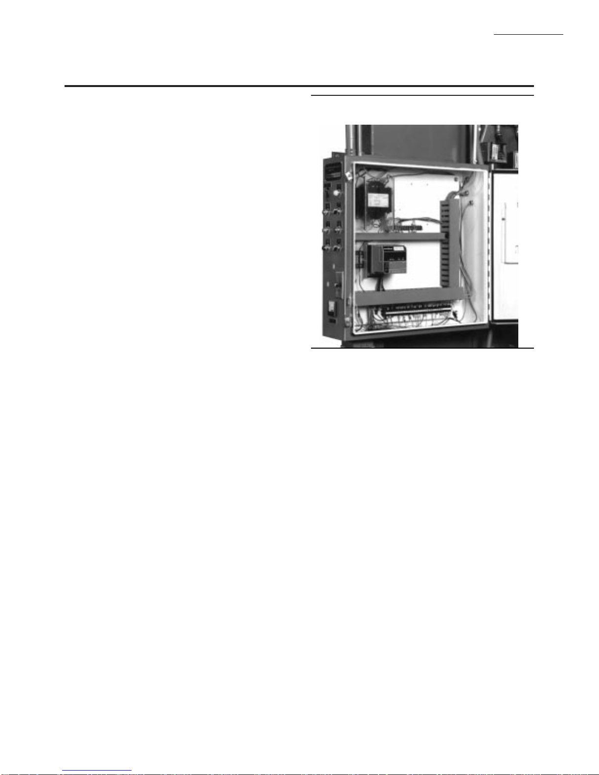
Fig. 11—Electrical panel installation.
IMPORTANT: The CB780/CB784 must be installed with a
plug-in motion rather than a hinge action.
4. Mount the CB780/CB784 by aligning the four L shaped
corner guides and knife blade terminals with the bifurcated
contacts on the wiring subbase and tightening the two screws
securely without deforming the plastic.
INSTALLING THE PURGE CARD
1. Remove the Keyboard Display Module or Control
Bus, see Fig. 13 or 14.
2. Remove the current Purge Card from the CB780/CB784
by pulling the plastic support cover upward .
3. Make sure that the Purge Card selected has the desired
timing.
4. Insert Purge Card into the opening of the CB780/CB784
compartment, see Fig. 12.
5. Reinstall the Keyboard Display Module or Control
Bus onto the CB780/CB784 and restore power to the
device.
6. Run the burner system through at least one complete
cycle to verify the system is operating as desired.
IMPORTANT: The CB780 will not function properly with-
out one of the following mounted correctly: Keyboard
Display Module, or Control Bus .
MOUNTING KEYBOARD DISPLAY MODULE
(VFD)
1. Align the two interlocking ears of the Keyboard Display Module with the two mating slots on the CB780/CB784;
see Fig. 13.
2. Insert the two interlocking ears into the two mating slots
and with a hinge action push on the lower corners of the
Keyboard Display Module to secure it to the CB780/CB784.
3. Verify the Keyboard Display Module is firmly in place.
MOUNTING CONTROL BUS
1. Align the two interlocking ears with the two mating
slots on the CB780/CB784; see Fig. 14.
2. Insert the two interlocking ears into the two mating
slots and push on the lower corners of the Control Bus to
secure it to the CB780/CB784.
3. Be sure the Control Bus is firmly in place.
750-166 1-15
Page 20

CB780/CB784
ASSEMBLY
Fig. 12—Purge Card installation.
MODULE (VFD)
1. The Keyboard Display Module (VFD) can be mounted
either on the face of a panel door or on other remote locations;
see Fig. 15.
2. When mounting the Keyboard Display Module on the
face of a door panel, closely follow these instructions:
a. Select the location on the door panel for flush mount-
ing. Pay attention to the insertion dimension of the two
Keyboard Display Module screws, two interlocking
ears and the two plug-in connectors to allow for
sufficient clearance, 1/4 inch minimum inward from
the surface of the door panel.
b. Use the Keyboard Display Module as a template; see
Fig. 28. Mark the two screw locations, two interlocking ear locations and two plug-in connector locations.
Drill the pilot holes for the mounting screws. Provide
for two holes on the door panel for the interlocking
ears and plug-in connector holes.
c. Mount the Keyboard Display Module securing the
two no. 4 screws.
Fig. 13—Keyboard Display Module mounting.
Fig. 14—Control Bus mounting.
REMOTE MOUNTING OF KEYBOARD DISPLAY
INSTALLING PLUG-IN FLAME SIGNAL
AMPLIFIER
1. Disconnect power supply before beginning installation
to prevent electrical shock and equipment damage. More than
one disconnect may be involved.
2. Align the amplifier circuit board edge connector with
the keyed receptacle on the CB780/CB784. Verify the amplifier nameplate faces away from the Relay Module, see
Fig. 16.
3. Push in the amplifier until the circuit board is fully
inserted into the receptacle and then push the amplifier
toward the CB780/CB784 retaining clasp.
4. Verify the amplifier is firmly in place.
5. Perform all required checkout tests.
INSTALLING THE FLAME DETECTOR
NOTE: Table 2 lists the flame detection systems available
for use with the CB780/CB784. Make sure the correct
combination of amplifier and flame detector(s) is used.
Proper flame detector installation is the basis of a safe and
reliable flame safeguard installation. Refer to the instructions packed with the flame detector and the equipment
manufacturer instructions; see Fig. 17.
Keep the flame signal leadwires as short as possible from
the flame detector to the wiring subbase. Capacitance increases with leadwire length, reducing the signal strength.
The maximum permissible leadwire length depends on the
type of flame detector, leadwire and conduit. The ultimate
limiting factor in the flame detector leadwire is the flame
signal; see Table 9.
1-16 750-166
Page 21

CB780/CB784
ASSEMBLY
Display Module.
Fig. 16—Flame signal amplifier mounting.
Fig.17—Flame detector wiring.Fig. 15—Remote mounting of Keyboard
INFRARED (817-1742)
F
3
G
ULTRAVIOLET (817-1743)
BLUE
F
1
WHITE
G
SOLID STATE SELF-CHECKING
ULTRAVIOLET (817-1121)
BLUE
F
YELLOW
2
G
WHITE
22
WHITE
L2
BLACK
L1
BLACK
L2
FLAME DETECTOR LEADS ARE COLOR CODED. THE BLUE LEAD
1
MUST BE CONNECTED TO THE F TERMINAL AND THE WHITE
MUST BE CONNECTED TO THE G TERMINAL. THE UV SENSING
TUBE IS POLARITY SENSITIVE. REVERSING THE LEADS EVEN
MOMENTARILY CAN DAMAGE OR DESTROY THE UV TUBE.
2
FLAME DETECTOR LEADS ARE COLOR CODED. THE BLUE LEAD
MUST BE CONNECTED TO THE F TERMINAL AND THE YELLOW
MUST BE CONNECTED TO THE G TERMINAL. THE UV SENSING
TUBE IS POLARITY SENSITIVE. REVERSING THE LEADS EVEN
MOMENTARILY CAN DAMAGE OR DESTROY THE UV TUBE.
3
1 BROWN WIRE AND 1 WHITE WIRE FROM THE 817-1742,
CONNECT TO THE CB 780/CB 784 WIRING SUBBASE, COLOR
NOT IMPORTANT. KEEP WIRES AS SHORT AS POSSIBLE
AND TWIST THEM.
M7410
750-166 1-17
Page 22

CB780/CB784
MAIN IGN 00:15
Flame Signal 2.7V
OPERATION
Operation
SEQUENCE OF OPERATION
The CB780/CB784 has the following operating sequence,
see Fig. 18 and Table 4.
INITIATE
The CB780/CB784 enters the INITIATE sequence when
the Relay Module is powered. The CB780/CB784 can also
enter the INITIATE sequence if the Relay Module verifies
voltage fluctuations of +10/-15% or frequency fluctuations
of +/-10% during any part of the operating sequence. The
INITIATE sequence lasts for ten seconds unless the voltage
or frequency tolerances are not met. When the tolerances are
not met, a hold condition will be initiated and will be
displayed on the VFD for at least five seconds. When the
tolerances are met, the INITIATE sequence will restart. If
the condition is not corrected and the hold condition exists
for four minutes, the CB780/CB784 will lockout. Causes for
hold conditions in the INITIATE sequence:
a. AC line dropout is detected.
b. AC line frequency error caused by using a 60 Hz device
on a 50 Hz line, or vice versa.
c. AC line noise that can prevent a sufficient reading of
the line voltage inputs.
d. Brownouts caused by a low line voltage.
The INITIATE sequence
also delays the burner motor
starter from being energized
INITIATE 00:10
Diagnostic Info
and de-energized from an
intermittent AC line input or control input.
STANDBY
The CB780/CB784 is
ready to start an operating
STANDBY
Total Cycles 132
sequence when the operating control determines a call for heat is present. The burner
switch, limits, operating control and all microcomputer monitored circuits must be in the correct state for the CB780/
CB784 to continue into the PREPURGE sequence.
NORMAL START-UP
PREPURGE
The CB780/CB784 pro-
PURGE 00:30
Total Hours 396
vides a PREPURGE timing
selectable from 30 seconds to 2-1/2 minutes with power
applied and the CB780/CB784 operating control indicating
a call for heat:
a. Running Interlocks, Preignition Interlocks, Burner
Switch, Run/Test Switch, Lockout Interlocks and all
microcomputer monitored circuits must be in the cor-
rect operating state.
b. The blower motor output, terminal 5, is powered to
start the PREPURGE sequence. The firing rate motor
is driven to the high fire position. The PREPURGE
timing does not begin until the Lockout Interlock
String and High Fire Switch are both closed.
c. The Preignition Interlock input must remain closed
throughout PREPURGE; otherwise, safety shutdown
occurs.
d. The Lockout Interlock or Running Interlock inputs
(interlock circuit including Airflow Switch) must close
by ten seconds into PREPURGE; otherwise, a safety
shutdown occurs.
e. After the firing rate motor reaches the PREPURGE
rate position and PREPURGE timing is completed, the
firing rate motor will drive to the low fire position.
f. When the firing rate motor reaches low fire position,
the Low Fire Switch, terminal 18, input must be
energized before entering the Ignition Trial state.
IGNITION TRIALS
a. Pilot Flame Establish-
ing Period (PFEP):
PILOT IGN 00:10
Fault History
1. With the firing
rate motor at the low fire position:
a. The pilot valve and the ignition transformer,
terminals 8, 10 and 21, are energized. The
CB780/CB784 has a fifteen second interrupted
pilot valve, terminal 21 and a ten second interrupted pilot valve/ignition, terminal 8.
b. During PFEP, the Low Fire Switch must remain
closed. If it opens, a safety shutdown occurs.
c. The Preignition Interlock input is ignored
throughout the Ignition Trial state.
2. Flame must be proven by the end of the four or ten
second PFEP to allow the sequence to continue. If
flame is not proven by the end of PFEP, a safety
shutdown occurs.
3. With flame proven, the ignition, terminal 10, is deenergized for early spark termination.
b. Main Flame Establish-
ing Period (MFEP):
1. T h e CB780/CB784
has a selectable ten second or fifteen second
MFEP. After the Ignition Trials, and with the presence of flame, the main fuel valve, terminal 9, is
powered. If a flameout occurs, the CB780/CB784
will lockout within 3 seconds.
RUN
1. A ten second stabilization period occurs at the begin-
ning of the RUN period.
2. The firing rate motor releases to modulation.
3. The CB780/CB784 is now in RUN and will remain in
RUN until the controller input, terminal 6, opens, indicating
that the demand is satisfied or a limit has opened.
POSTPURGE
The CB780/CB784 provides a fifteen second
POST-PURGE following
RUN
Expanded Annun.
the completion of the RUN
period. The blower motor output is powered to drive all
products of combustion and any unburned fuel from the
1-18 750-166
Page 23

CB780/CB784
OPERATION
combustion chamber. It also supplies combustion air to burn
fuel being purged from the fuel line downstream of the fuel
shutoff valve.
1. The main fuel valve and intermittent pilot valve, terminals 9 and 21, are de-energized and the firing rate motor is
commanded to the low fire position to begin the POSTPURGE
period.
Fig. 18—CB780/CB784 sequence.
PREPURGE
VFD
DISPLAY
LED
DISPLAY
BURNER
OPERATING
CONTROLS
AND
INTERLOCKS
FLAME
SIGNAL
FIRING
RATE
MOTOR
INITIATE
STANDBY
POWER
INTERLOCK CHECK
PREIGNITION INTERLOCK CLOSED
00
POWER
SAFE START CHECK
MOTOR OUTPUT SWITCHING
00 00 10 25 00 1520
DRIVE TO
HIGH FIRE
5
TIMED
PURGE
POWER
TO
POWER
PILOT
FLAME
MAIN
BURNER/BLOWER MOTOR
LIMITS AND BURNER CONTROLLER CLOSED
LOCKOUT INTERLOCKS CLOSED
19
HIGH FIRE SW.
12
13
TO
MOTOR ACTION
2. The Preignition
Interlock closes within the
first five seconds of
POSTPURGE.
3. After the fifteen second POSTPURGE period is completed, the CB780/CB784 reenters STANDBY.
CB 780/CB 784
PREPURGE
00
DRIVE TO
LOW FIRE
POWER
PILOT
FLAME
MAIN
PFEP
4 OR 10 SEC
POWER
PILOT
FLAME
MAIN
IGN.
10
10 SEC. IGN./PILOT
15 SEC. PILOT
4
LOW FIRE SW.
5 SEC.
20TO
MFEP
POWER
PILOT
FLAME
MAIN
ALARMALARMALARMALARM
8
21
MAIN VALVE
L1
TO
6
18
5
TO
FLAME PROVING
14
13
TO
RUN
POWER
PILOT
FLAME
MAIN
ALARM
5
6
7TO
13 15
TO
9
POST PURGE 00:12
Flame Signal 0.0V
Device RM7800L
POSTPURGE
13
POWER
TO
STANDBY
POWER
IC
PII
SSC
14
KEYBOARD DISPLAY MODULE (VFD)
The first line of the Vacuum Fluorescent Display (VFD)
provides current status of the burner sequence (STANDBY,
PURGE, PILOT IGN, MAIN IGN, RUN and POSTPURGE), timing information (PURGE, PILOT IGN, MAIN
IGN and POSTPURGE) in minutes and seconds, hold information (PURGE HOLD: T19) and lockout information
(Lockout, Fault Code, Message and Sequence); see Fig. 19.
The extreme right side of the first line will either be blank or
it will show a small arrow pointing to the second line
followed by a two-letter code (DI-Diagnostic Information,
Hn-Fault History Information, and EA-Expanded Annunciator). When the arrow and two-letter code are displayed, it
indicates the second line is showing a selectable message
submenu. The second line will display selectable or preemptive messages. A selectable message supplies information for
flame strength, system status indication, system or self-diagnostics and troubleshooting. A preemptive message will have
parentheses around the message and supply a detailed message to support the sequence status information. A preemptive message can also be a lockout message. A preemptive
M7411
Fig. 19—Keyboard Display Module and
sequence status LEDs (Table 4).
FIVE WIRE CONNECTOR FOR
COMMUNICATIONS, REMOTE
KEYBOARD DISPLAY AND REMOTE RESET
RUN/TEST SWITCH
SEQUENCE
STATUS
SELECTABLE
MESSAGE OR
PREEMPTIVE
MESSAGE
SEQUENCE
STATUS
LEDs
RESET
PUSH
BUTTON
FLAME
SIMULATOR INPUT
* NOTE: REMOTE RESET MUST BE MOUNTED WITHIN SIGHT
OF THE BOILER CONTROL PANEL.
*
FLAME CURRENT
TEST JACKS
DI = DIAGNOSTICS
H1 = HISTORY
EA = EXPANDED
ANNUNCIATOR
CAPTIVE
MOUNTING
SCREW
PLUG-IN
PURGE
CARD
KEYBOARD
DISPLAY
MODULE
RELAY
MODULE
FLAME
AMPLIFIER
M7395
750-166 1-19
Page 24

CB780/CB784
OPERATION
message will replace a selectable message to support the
sequence status information. It will also replace a selectable
message after 60 seconds if it or a lockout message is
TABLE 4—SEQUENCE STATUS DISPLAY INFORMATION (See Fig. 19).
NOTE: Normal sequences are in BOLD TYPE, while abnormal sequences are not in bold type.
Burner Sequence LEDs Energized
INITIATE minutes:seconds
POWER, PILOT, FLAME, MAIN AND ALARM
↕selectable—message
INITIATE HOLD: AC
POWER, PILOT, FLAME, MAIN AND ALARM
(AC Freq/Noise)
INITIATE HOLD: AC
POWER, PILOT, FLAME, MAIN AND ALARM
(AC Line Dropout)
INITIATE HOLD: AC
POWER, PILOT, FLAME, MAIN AND ALARM
(AC Frequency)
INITIATE HOLD: AC
POWER, PILOT, FLAME, MAIN AND ALARM
(Low Line Voltage)
STANDBY
POWER, PILOT, FLAME, MAIN AND ALARM
↕selectable —message
STANDBY HOLD: REM
POWER, PILOT, FLAME, MAIN AND ALARM
(Remote Control)
STANDBY HOLD: F/G
POWER, PILOT, FLAME, MAIN AND ALARM
(Flame Detected)
STANDBY HOLD: T20
POWER, PILOT, FLAME, MAIN AND ALARM
(Preignition ILK)
STANDBY HOLD: T7
POWER, PILOT, FLAME, MAIN AND ALARM
(Running ILK)
STANDBY HOLD: T7
POWER, PILOT, FLAME, MAIN AND ALARM
(Lockout ILK)
PURGE HOLD: T19
POWER, PILOT, FLAME, MAIN AND ALARM
(High Fire Switch)
PURGE DELAY: T19
POWER, PILOT, FLAME, MAIN AND ALARM
(High Fire Jumprd)
PURGE HOLD: TEST
POWER, PILOT, FLAME, MAIN AND ALARM
(Run/Test Switch)
PURGE DELAY: T18
POWER, PILOT, FLAME, MAIN AND ALARM
(Low Fire Jumprd)
PURGE HOLD: F/G
POWER, PILOT, FLAME, MAIN AND ALARM
(Flame Detected)
PURGE HOLD: T18
POWER, PILOT, FLAME, MAIN AND ALARM
(Low Fire Switch)
PURGE minutes:seconds
POWER, PILOT, FLAME, MAIN AND ALARM
↕selectable—message
PURGE HOLD: T7
POWER, PILOT, FLAME, MAIN AND ALARM
(Running ILK)
PILOT IGN minutes:seconds
POWER, PILOT, FLAME, MAIN AND ALARM
↕selectable—message
PILOT HOLD: TEST
POWER, PILOT, FLAME, MAIN AND ALARM
(Run/Test Switch)
MAIN IGN minutes:seconds
POWER, PILOT, FLAME, MAIN AND ALARM
↕selectable—message
RUN
POWER, PILOT, FLAME, MAIN AND ALARM
↕selectable—message
RUN
POWER, PILOT, FLAME, MAIN AND ALARM
↕selectable—message
RUN LOWFIRE: TEST
POWER, PILOT, FLAME, MAIN AND ALARM
(Run/Test Switch)
available. The CB780/CB784 LEDs provide positive visual
indication of the program sequence: POWER, PILOT,
FLAME, MAIN and ALARM.
(continued)
1-20 750-166
Page 25

CB780/CB784
OPERATION
TABLE 4—SEQUENCE STATUS DISPLAY INFORMATION (See Fig. 19) (Continued).
NOTE: Normal sequences are in BOLD TYPE, while abnormal sequences are not in bold type.
Burner Sequence LEDs Energized
POSTPURGE minutes:seconds
POWER, PILOT, FLAME, MAIN AND ALARM
↕selectable—message
Waiting for connection… POWER, PILOT, FLAME, MAIN AND ALARM
RESET/ALARM TEST
POWER, PILOT, FLAME, MAIN AND ALARM
↕selectable—message
Additional sequence status information when an Expanded Annunciator is connected to the relay module, also see
Additioanl sequence status information when an Expanded Annunciator is connected to the relay module. Also see
CB 780/CB 784 System Annunciation Diagnostics and Troubleshooting, Bulletin Number CB-7803.
CB780/CB784 Operating and Maintenance Manual, Manual Number 750-166.
BURNER OFF: T6
POWER,PILOT, FLAME, MAIN AND ALARM
(Burner Switch)
STANDBY HOLD: T6
POWER, PILOT, FLAME, MAIN AND ALARM
(Expanded Annunciator hold message)
STANDBY HOLD: T6
POWER, PILOT, FLAME, MAIN AND ALARM
(Circuit Fault)
KEYBOARD FUNCTIONS
The keyboard contains four pushbuttons and each has
separate functions (SCROLL-Down, SCROLL-Up, MODE
and Change-Level). The MODE and Change-Level pushbuttons, when pressed together, provide a SAVE function.
1. SCROLL Down-Up pushbuttons (↕), see Fig. 20.
The SCROLL Down-Up pushbuttons (↕) are used to
scroll through the selectable messages. The double-headed
Fig. 20—(↕) SCROLL pushbutton function.
BURNER CONTROL
RUN
Total Cycles 333
SCROLL
MODE
SAVE
arrow (↕), which is located in the lower left position of the
second line of the display, represents the SCROLL DownUp pushbuttons. The SCROLL Down-Up pushbuttons (↕)
can be pressed to display selectable messages one at a time or
held down to scroll through the selectable messages at a rate
of two per second. When the last item of the selectable
message is viewed, the display wraps around and displays
the first selectable message again.
BURNER CONTROL
RUN
Total Hours 1332
SCROLL
MODE
SAVE
M7401
2. Change-Level pushbutton (↔), see Fig. 21.
The Change-Level pushbutton is used to change between
the first hierarchy of selectable messages to a subset of
selectable messages. The Change-Level pushbutton can also
be used to change from a subset message to a first level
selectable message. The symbol (>) located on the second
line in the lower right corner of the VFD represents a first
level hierarchy of selectable messages. The symbol (<)
located on the second line in the lower right corner of the
VFD represents a subset of selectable messages.
750-166 1-21
3. MODE pushbutton, see Fig. 22.
The MODE pushbutton instantaneously switches the
display from a second-line-selectable message to second-
line-preempted message. The sixty second timeout function
also can be used for this task. The MODE pushbutton will
work only if there is a second-line-preempted message or
lockout message.
Page 26

CB780/CB784
OPERATION
Fig. 21 (↔)—Change-Level pushbutton function.
BURNER CONTROL
PILOT IGN 00:05
Fault History
SCROLL
MODE
Fig. 22—MODE pushbutton function.
BURNER CONTROL
LOCKOUT #17 MFEP
Main Valve T9 Off
SCROLL
MODE
SAVE
SAVE
BURNER CONTROL
PILOT IGN 00:10 H1
Fault Cycle 174
SCROLL
MODE
BURNER CONTROL
LOCKOUT #17 MFEP
*Main Flame Fail*
SCROLL
MODE
SAVE
SAVE
M7402
The SAVE function enables users to identify the selectable message they want to view upon power restoration. The
second line selectable message will be restored to the most
recently saved selection when power returns. The SAVE
function is performed by pressing and holding the MODE
key and then pressing the Change-Level pushbutton (↔).
The second line of the display will briefly note “…SAVING…” to confirm the key press.
SELECTABLE MESSAGES
VFD Second Line Display, Two-Level Hierarchy, see
Table 5.
The display values are as follows:
n represents a numbered value.
T represents the terminal number.
x represents the suffix letter of the Relay Module.
M7403
Fig. 23—SAVE function.4. SAVE function; see Fig. 23.
BURNER CONTROL
PURGE 00:30
... SAVING ...
SCROLL
MODE
SAVE
M7404
1-22 750-166
Page 27

CB780/CB784
OPERATION
TABLE 5—SELECTABLE MESSAGES.
Selectable Message Display Value First Line
(Second Line) (Second Line) Message
↕Flame Signal n.nV
↕Total Cycles nnnnn
↕Total Hours nnnnn
↕Fault History↔
↕Fault Cycle nnnnn < ↓H1
↕Fault Hours nnnnn < ↓H1
↕Fault Code nnn < ↓H1
↕*fault —message*< ↓H1
↕sequence—message< ↓H1
↕(second-line-msg)< ↓H1
↕Fault Cycle nnnnn < ↓H2
↕Fault Hours nnnnn < ↓H2
↕Fault Code nnn < ↓H2
↕*fault —message*< ↓H2
↕sequence—message< ↓H2
↕(second-line-msg)< ↓H2
↕Fault Cycle nnnnn < ↓H3
↕Fault Hours nnnnn < ↓H3
↕Fault Code nnn < ↓H3
↕*fault —message*< ↓H3
↕sequence—message< ↓H3
↕(second-line-msg)< ↓H3
↕Fault Cycle nnnnn < ↓H4
↕Fault Hours nnnnn < ↓H4
↕Fault Code nnn < ↓H4
↕*fault —message*< ↓H4
↕sequence—message< ↓H4
↕(second-line-msg)< ↓H4
↕Fault Cycle nnnnn < ↓H5
↕Fault Hours nnnnn < ↓H5
↕Fault Code nnn < ↓H5
↕*fault —message*< ↓H5
↕sequence—message< ↓H5
↕(second-line-msg)< ↓H5
↕Fault Cycle nnnnn < ↓H6
↕Fault Hours nnnnn < ↓H6
↕Fault Code nnn < ↓H6
↕*fault —message*< ↓H6
↕sequence—message< ↓H6
↕(second-line-msg)< ↓H6
↕Diagnostic Info↔
↕Device RM78nnx < ↓DI
↕Device Suffix nnnn < ↓DI
↕Run/Test Sw. RUN or TEST < ↓DI
↕Operating Control (OperControl) T6 ON or OFF < ↓DI
↕Interlock T7 ON or OFF < ↓DI
↕Pilot Valve T8 ON or OFF < ↓DI
↕Main Valve T9 ON or OFF < ↓DI
↕Ignition T10 ON or OFF < ↓DI
↕LowFire Sw T18 ON or OFF < ↓DI
↕HighFireSw T19 ON or OFF < ↓DI
↕Preignition Interlock (PreIgn ILK) T20 ON or OFF < ↓DI
↕Pilot Valve/First Stage OilValve (Valv/Start,V25) T21 ON or OFF < ↓DI
↕Jumper 1 INTACT or CLIPPED < ↓DI
↕Jumper 2 INTACT or CLIPPED < ↓DI
↕Jumper 3 INTACT or CLIPPED < ↓DI
↕Amplifier Type (Amp Type) NORMAL or AMP-CHECK or SHUTTER ↓DI
↕Flame Response 0.8s or 3s < ↓DI
↕Purge Time mm:ss < ↓DI
↕Manufacturing Code (Mfg Code) nnnn < ↓DI
↕Software Revision (SW Rev.) nnnn/nnnn < ↓DI
↕Expanded Annun.↔ (see Table 5)
↕Remote Command NONE/HOLD/HF/LF
750-166 1-23
Page 28

CB780/CB784
OPERATION
EXPANDED ANNUNCIATOR MESSAGES,
SEE TABLE 6
The Expanded Annunciator (EA) may or may not be
connected because it is an optional device. If the EA is not
connected, a display message of “(EA not connected)” will
shown, see Table 6 and the Diagnostic and Troubleshooting
section of the CB780/CB784 Operation and Maintenance
Manual, Manual No. 750-166, Tables 6 and 7 for fault codes.
When accessing Expanded Annunciator Messages, follow
the same operations as used with the Selectable Messages.
be shown. If the EA is connected, display messages will be
TABLE 6—EXPANDED ANNUNCIATOR MESSAGES.
Selectable Message Display Value First Line
(Second Line) (Second Line) Message
↕Expanded Annun.↔
↕Expanded Annunciator (EA not connected)<
↕Current Status (CS:)
↕Valve Closure (Valve Close) T4 ON or OFF< ↓EA
↕Burner Switch (Burner Sw.) T5 ON or OFF< ↓EA
↕Operating Control (OperControl) T6 ON or OFF< ↓EA
↕Auxiliary Limit (Aux Limit 1) T7 ON or OFF< ↓EA
↕Auxiliary Limit (Aux Limit 2) T8 ON or OFF< ↓EA
↕Low Water Cutoff (LWCO) T9 ON or OFF< ↓EA
↕High Limit (High Limit) T10 ON or OFF< ↓EA
↕Auxiliary Limit (AuxLimit 3) T11 ON or OFF< ↓EA
↕Oil Selection Switch (Oil Select) T12 ON or OFF< ↓EA
↕High Oil Pressure Switch (Hi OilPres) T13 ON or OFF< ↓EA
↕Low Oil Pressure Switch (LowOilPres) T14 ON or OFF< ↓EA
↕High Oil Temperature Switch (Hi OilTemp) T15 ON or OFF< ↓EA
↕Low Oil Temperature Switch (LowOilTemp) T16 ON or OFF< ↓EA
↕Atomizing Switch (Atomize Sw) T19 ON or OFF< ↓EA
↕Gas Selection Switch (Gas Select) T17 ON or OFF< ↓EA
↕High Gas Pressure Switch (Hi GasPres) T18 ON or OFF< ↓EA
↕Low Gas Pressure Switch (LowGasPres) T19 ON or OFF< ↓EA
↕Airflow Switch (Airflow Sw) T20 ON or OFF< ↓EA
↕Auxiliary Interlock (Aux ILK 4) T21 ON or OFF< ↓EA
↕Auxiliary Interlock (Aux ILK 5) T22 ON or OFF< ↓EA
↕EA Fault Code nnn< ↓EA
↕Software Revision (SW Rev.) nnnn< ↓EA
a
Expanded Annunciator Diagnostic Current Status Messages can be reviewed in CB780/CB784 Operating and Maintenance
a
EA Message< ↓EA
Manual, Manual Number 750-166.
RUN/TEST SWITCH FUNCTIONS
The Run/Test Switch is located on the top side of the
CB780/CB784; see Fig. 19. The Run/Test Switch allows the
burner sequence to be altered as follows:
1. In Prepurge Drive To High Fire Position, the Run/Test
Switch, when placed in the TEST position, will hold in
PREPURGE with the firing rate motor in the High Fire
position.
2. In the measured PREPURGE sequence, the Run/Test
Switch, when placed in the TEST position, will cause the
PREPURGE timing to stop. The firing rate motor will be in
the High Fire position.
3. In Prepurge Drive to Low Fire position, the Run/Test
Switch, when placed in the TEST position, will hold the
burner sequence in PREPURGE with the firing rate motor in
the Low Fire position.
4. In PFEP, the Run/Test Switch, when placed in the
TEST position, will stop the timer during the first eight
seconds when a ten second PFEP is selected or during the
first three seconds when a four second PFEP is selected,
allowing pilot-turn-down test and other burner adjustments
1-24 750-166
to be made. This activates a fifteen second flameout timer
that permits pilot flame adjustment without nuisance safety
shutdowns. The Run/Test Switch will be ignored during
PFEP for the CB780/CB784 if terminals 8 and 9 or 9 and 21
are jumpered.
5. During RUN, the Run/Test Switch, when placed in the
TEST position, will drive the firing rate motor to the Low
Fire position.
NOTE: When CB780/CB784 is switched to the TEST mode,
it will stop and hold at the next Run/Test Switch point in
the operating sequence. Make sure that the Run/Test
Switch is in the RUN position before leaving the installation.
SELECTABLE SITE-CONFIGURABLE JUMPERS
The CB780/CB784 has two site-configurable jumper
options; see Fig. 24 and Table 7. The site-configurable
jumpers should be clipped with side cutters and the resistors
removed from the Relay Module.
Page 29

TABLE 7—SITE CONFIGURABLE
JUMPER OPTIONS.
Jumper
Number Description Intact Clipped
JR1 Pilot Flame
Establishing
Period (PFEP)
JR3 Start-up
Interlock Check
NOTE: For all standard installations, these jumpers
should be left intact, unless otherwise indicated on
wiring diagram.
10 Seconds 4 Seconds
Disabled Enabled
CB780/CB784
OPERATION • STATIC CHECKOUT
Fig. 24—Selectable site-configurable jumpers.
SELECTABLE CONFIGURATION JUMPERS
RUN/TEST SWITCH
M7397
CA UTION
1. Use extreme care while testing the system. Line
voltage is present on most terminal connections
when power is on.
2. Open the master switch before installing or
removing a jumper on the subbase.
3. Before continuing to the next test, be sure to
remove test jumper(s) used in the previous test.
4. Replace all limits and interlocks that are not
operating properly. Do not bypass limits and
interlocks.
5. Close all manual fuel shutoff valve(s) before
starting these tests.
After checking all wiring, perform this checkout before
installing the CB780/CB784 on the subbase. These tests
verify the Wiring Subbase is wired correctly, and the external controllers, limits, interlocks, actuators, valves, transformers, motors and other devices are operating properly.
NOTE: Do not perform a dielectric test with theCB780/CB784
installed. Internal surge protectors will break down and
conduct a current. This could cause the CB780/CB784 to
fail the dielectric test or possibly destroy the internal
lightning and high current protection.
Static Checkout
EQUIPMENT RECOMMENDED
1. Voltmeter (20 kohm/volt minimum sensitivity) set on
the 0-300 Vac scale.
2. Two jumper wires; no. 14 wire, insulated, 12 inches
[304.8 mm] long with insulated alligator clips at both ends.
GENERAL INSTRUCTIONS
1. Perform all applicable tests listed in Static Checkout,
Table 8, in the order listed.
2. Make sure all manual fuel shutoff valve(s) are closed.
3. Raise the setpoint of the operating controller to simu-
late a call for heat.
4. For each test, open the master switch and install the
jumper wire(s) between the subbase wiring terminals listed
in the Test Jumpers column.
5. Close the master switch before observing operation.
6. Read the voltage between the subbase wiring termi-
nals listed in the Voltmeter column.
7. If there is no voltage or the operation is abnormal,
check the circuits and external devices as described in the
last column.
8. Check all wiring for correct connections, tight terminal screws, correct wire, and proper wiring techniques. Replace all damaged or incorrectly sized wires.
9. Replace faulty controllers, limits, interlocks, actuators,
valves, transformers, motors and other devices as required.
10. Ensure normal operation is obtained for each required
test before continuing the checkout.
11. After completing each test, be sure to remove the
test jumper(s).
750-166 1-25
Page 30

CB780/CB784
STATIC CHECKOUT
Test
No.
Test
Jumpers
WARNING
Make sure all manual fuel shutoff valves are closed.
IMPORTANT: Low fuel pressure limits, if used, could be open. Bypass them with jumpers for the remaining Static
Tests (if required).
2 None 6-L2 Line voltage at terminal 6. 1. Limits.
3 None 20-L2 Line voltage at terminal 20. 1. Preignition interlocks.
4 4-5 7-L2 1. Burner motor (fan or blower) starts.
5 4-10 — Ignition spark (if ignition transformer is
6 4-8 — 1. Ignition spark (if ignition transformer is
7 4-21 — Same as test no. 6 for connections to terminal 8.
8 4-9 — Automatic main fuel valve(s) open. If using
9 4-3 — Alarm (if used) turns on. 1. Alarm.
10. 4-5 and
12-13
11 4-5 and
14-13
12 4-5 and
12-13
13 4-5 and
14-13
TABLE 8—STATIC CHECKOUT.
Volt-
meter Normal Operation
1None 4-L2 Line voltage at terminal 4. 1. Master switch.
2. Line voltage at terminal 7 within
10 seconds.
connected to terminal 10).
connected to terminal 8).
2. Automatic pilot valve opens (if connected to terminal 8).
NOTE: Refer to wiring diagram of system
being tested.
If using direct spark ignition, check the first
stage fuel valve(s) instead of pilot valve.
direct spark ignition with intermittent pilot on
terminal 21, check the optional second stage
fuel valve, if used.
18-L2 Firing rate motor drives open; zero volts at
terminal 18 after motor starts driving open.
18-L2 Firing rate motor drives closed; line voltage at
terminal 18 after motor is in Low Fire position.
19-L2 Firing rate motor drives open; line voltage at
terminal 19 after motor is in High Fire position.
19-L2 Firing rate motor drives closed; zero volts at
terminal 19 after m otor starts driving closed.
If Operation is Abnormal, Check the
Items Listed Below
2. Power connected to the master
switch.
3. Overload protection (fuse, circuit
breaker, etc.) has not opened the
power line.
2. Burner controller.
1. Burner motor circuit.
a. Manual switch of burner motor.
b. Burner motor power supply,
overload protection, and starter.
c. Burner motor.
2. Running or Lockout Interlocks
(including Airflow Switch).
1. Watch for spark or listen for buzz.
a. Ignition electrodes are clean.
b. Ignition transformer is okay.
1. Watch for spark or listen for buzz.
a. Ignition electrodes are clean.
b. Ignition transformer is okay.
2. Listen for click or feel head of valve
for activation.
a. Actuator if used.
b. Pilot valve.
Same as test no. 6. If using direct spark
ignition, check the first stage fuel valve(s)
isntead of the pilot valve.
1. Listen for and observe operation of
the main fuel valve(s) and actuator(s).
2. Valve(s) and actuator(s).
1. Low Fire Start Switch.
2. Firing rate motor and transformer.
1. Low Fire Start switch.
2. Firing rate motor and transformer.
1. High Fire Purge Switch.
2. Firing rate motor and transformer.
1. Low Fire Start Switch.
2. Firing rate motor and transformer.
1-26 750-166
(Continued)
Page 31

CB780/CB784
STATIC CHECKOUT • CHECKOUT
TABLE 8—STATIC CHECKOUT (Continued).
Test
No.
IMPORTANT: Low fuel pressure limits, if used, could be open. Bypass them with jumpers for the remaining Static
14 15-13 — 1. Raise set point of Series 90 controller—
Final
Test
Jumpers
WARNING
Make sure all manual fuel shutoff valves are closed.
Tests (if required).
Volt-
meter Normal Operation
firing rate motor should drive toward open.
2. Lower setpoint of Series 90 controller—
firing rate motor should drive toward
closed.
CAUTION
On completing these tests, open the master switch and remove all test jumpers from the subbase
terminals. Also remove bypass jumpers from the low fuel pressure limits (if used).
If Operation is Abnormal, Check the
Items Listed Below
1. Series 90 Controller.
2. Firing rate motor and transformer.
Checkout
WARNING
Do not allow fuel to accumulate in the combus-
tion chamber. If fuel is allowed to enter the
chamber for longer than a few seconds without
igniting, an explosive mixture could result. It is
recommended that you limit the trial for pilot to
ten seconds, and limit the attempt to light the main
burner to two seconds from the time the fuel has
reached the burner nozzle. In any case, do not
exceed the nominal lightoff time specified by the
equipment manufacturer; close the manual fuel
shutoff valve(s) if the flame is not burning at the
end of the specified time.
CA UTION
1. Use extreme care while testing the system. Line
voltage is present on most terminal connections
when power is on.
2. Open the master switch before removing or in-
stalling the CB780/CB784 or Keyboard Dis-
play Module connector.
3. Make sure all manual fuel shutoff valve(s) are
closed before starting the initial lightoff check
and the Pilot Turndown tests.
4. Do not put the system in service until you have
satisfactorily completed all applicable tests in
this section and any others required by the
equipment manufacturer.
IMPORTANT:
1. If the system fails to perform properly, note the fault
code, fault message, equipment status, and sequence
time on the display. Refer to the Troubleshooting section of the CB780/CB784 Operation and Maintenance
Manual, Manual Number 750-166.
2. Repeat ALL required Checkout tests after all adjustments are made. ALL tests must be satisfied with the
flame detector(s) in its FINAL position.
EQUIPMENT RECOMMENDED
Volt-ohmmeter (20 kohm/volt minimum sensitivity) with:
• 0-300 Vac capability.
• 0-6000 ohm capability.
• 0-10 Vdc capability.
CHECKOUT SUMMARY
• Preliminary inspection—all installations.
• Flame signal measurement—all installations.
• Initial lightoff check for proved pilot—all installations
using a pilot.
• Initial lightoff check for direct spark ignition of oil—
all burners using DSI.
• Pilot turndown test—all installations using a pilot.
• Hot refractory saturation test—all installations using
Infrared (lead sulfide) Flame Detectors.
• Hot refractory hold-in test—all installations.
• Ignition interference test—all installations using flame
rods.
• Ignition spark pickup—all installations using Ultraviolet Flame Detectors.
• Response to other ultraviolet sources—all installations using Ultraviolet Flame Detectors.
750-166 1-27
Page 32

CB780/CB784
CHECKOUT
• Flame signal with hot combustion chamber—all
installations.
• Safety shutdown tests—all installations.
See Figs. 1 and 2 for location of component parts and
Fig. 7 or wiring subbase specifications for terminal locations.
7. Power is connected to the system disconnect switch,
(master switch).
8. Lockout is reset (push in reset button) only if the Relay
Module is powered; see Figs. 1 and 2.
9. Run/Test Switch is in RUN position.
10. System is in the STANDBY condition. STANDBY
PRELIMINARY INSPECTION
Perform the following inspections to avoid common
message is viewable in the VFD.
11. All limits and interlocks are reset.
problems. Make certain that:
1. Wiring connections are correct and all terminal screws
are tight.
2. Flame detector(s) is clean, and installed and positioned
properly. Consult the applicable instructions.
3. Correct combination of amplifier and flame detec-
tor(s) is used. See Table 2 in the Specifications section.
4. Plug-in amplifier and purge card are securely in place.
5. Burner is completely installed and ready to fire; con-
sult equipment manufacturer instructions. Fuel lines are
purged of air.
6. Combustion chamber and flues are clear of fuel and
fuel vapor.
FLAME SIGNAL MEASUREMENT
(TABLE 9 AND FIG. 26)
Measure the flame signal at the appropriate times as
defined in the following Checkout tests. Read the flame
signal in volts dc at the flame amplifier test jacks + and
(Com) or at the Keyboard Display Module.
1. Use 1M ohm/volt meter with a 0 to 10 Vdc capability.
2. Set the 1M ohm/volt meter to the 0 to 10 Vdc range.
3. Insert the positive (red) probe into the + jack of the
flame amplifier. Insert the negative (black) probe into the
(Com) jack of the flame amplifier; see Fig. 26.
4. Allow a few seconds for the meter reading to stabilize.
TABLE 9—FLAME SIGNAL.
Flame
Detector
817-1121 833-2741
817-1742 833-2722 or
Flame Signal
Amplifier
b
833-2723
c
Minimum Acceptable
Steady dc Voltage
a
Maximum Expected
1.25 Vdc 5.0 Vdc at Keyboard
Display Module
or
dc Voltage
817-1743 833-2724 5.0 Vdc at 1M ohm/volt meter
a
This minimum or stronger signal should easily be obtained if the detector is correctly installed and positioned to properly sense
the flame. This voltaged must be obtained before completing checkout.
b
The flame signal amplifier circuitry istested one-half second every five seconds during burner operation and shuts down the
burner if the amplifier fails (all installations).
c
This flame amplifier is Auto-Check type.
5. If using Auto-Check or shutter check amplifiers, read
Fig. 26—Flame signal measurement.
the average stable voltage, disregarding the peaks and valleys caused by the self-checking operation.
6. The meter reading must be as specified in Table 8 after
all tests are completed and all adjustments made.
As an option, the flame signal can be checked by using the
Keyboard Display Module.
NEGATIVE (-)
METER LEAD
POSITIVE (+)
METER LEAD
ONE
MEGOHM/VOLT
METER
If the signal is unstable or less than the minimum accept-
able voltage, check flame detector installation and circuitry.
1. Check the supply voltages at terminals 4 (L1) and L2
(N). Make sure the master switch is closed, connections are
correct, and the power supply is of the correct voltage, frequency and is sinusoidal.
2. Check the detector wiring for defects including:
• Incorrect connections.
• Wrong type of wire.
• Deteriorated wire.
• Open circuits.
M7383
• Short circuits.
• Leakage paths caused by moisture, soot or accumulated dirt.
1-28 750-166
Page 33

CB780/CB784
CHECKOUT
3. For all optical detectors, clean the detector viewing
window and inside of the sight pipe as applicable.
4. With the burner running, check temperature at the de-
tector. If it exceeds the detector maximum rated temperature:
• Add a heat block to stop conducted heat traveling
up the sight pipe.
• Add a shield or screen to reflect radiated heat.
• Add cooling (refer to sight pipe ventilation in the
detector Instructions).
5. Make sure the flame adjustment is not too lean.
6. Make sure the detector is properly sighting the flame.
7. If necessary, resight or reposition the detector.
INITIAL LIGHTOFF CHECK FOR PROVED
PILOT
Perform this check on all installations that use a pilot. It
should immediately follow the preliminary inspection.
NOTE: Low fuel pressure limits, if used, could be open. If
so, bypass them with jumpers during this check.
1. Open the master switch.
2. Make sure that the manual main fuel shutoff valve(s)
is closed. Open the manual pilot shutoff valve. If the pilot
takeoff is downstream from the manual main fuel shutoff
valve(s), very slightly open the manual main valve to supply
pilot gas flow. Make sure the main fuel is shut off just upstream from the burner inlet, or disconnect power from the
automatic main fuel valve(s).
3. Close the master switch and start the system with a
call for heat by raising the set point of the operating controller; see Fig. 19 or CB780/CB784 sequence. The program
should start the ten second INITIATE sequence.
4. Let the sequence advance through PREPURGE. When
the PILOT IGN status is displayed on the Keyboard Display
Module, ignition spark should occur and the pilot should
light. If the pilot ignites, the FLAME LED will be energized.
Proceed to step 7.
5. If the pilot flame is not established in ten seconds, safety
shutdown occurs. Let the sequence complete its cycle. Consult
the equipment operating manual for further information.
6. Push the reset pushbutton, and let the system recycle
once. If the pilot still does not ignite, make the following
ignition/pilot adjustments:
a. Open master switch and remove the CB780/CB784
from the subbase.
b. On the subbase, temporarily jumper terminal 4 to
ignition terminals 8, 10 or 21; refer to the appropriate wiring diagram to determine the proper terminal. Disconnect the leadwire to the pilot valve if it
is connected to the same terminal.
c. Close the master switch to energize only the igni-
tion transformer.
d. If the ignition spark is not strong and continuous,
open the master switch and adjust the ignition
electrode spark gap setting to the manufacturer
recommendations.
e. Make sure the ignition electrodes are clean.
f. Close the master switch and observe the spark.
g. After a continuous spark is obtained, open the master
switch and add a jumper on the subbase from
terminal 4 (L1) to the pilot terminal 8 or 21. Reconnect the leadwire from the pilot valve if it was
disconnected in step b.
h. Close the master switch to energize both the igni-
tion transformer and the pilot valve.
i. If the pilot does not ignite and if the ignition spark
is still continuous, adjust the pressure regulator until
a pilot is established.
j. When the pilot ignites properly and stays ignited,
open the master switch and remove the jumper(s)
from terminals 4-8, 4-10 and 4-21 of the subbase.
k. Check for adequate bleeding of the fuel line.
l. Reinstall the CB780/CB784 on the subbase, close
the master switch, and then return to step 4.
7. When pilot ignites, measure the flame signal. If the
pilot flame signal is unsteady or approaching the 1.25 Vdc
minimum value, adjust the pilot flame size or detector
sighting to provide a maximum and steady flame signal.
8. Recycle the system to recheck lightoff and pilot flame
signal.
9. When the MAIN IGN period is displayed on the VFD,
make sure the automatic main fuel valve is open; then
smoothly open the manual main fuel shutoff valve(s) and
watch for main burner flame ignition. When the main burner
flame is established, proceed to step 15.
10. If the main burner flame is not established within
ten second s, close the manual main fuel shutoff valve(s).
11. Recycle the system to recheck the lightoff and pilot
flame signal.
12. Smoothly open the manual fuel shutoff valve(s) and
try lightoff again. (The first reattempt may have been required to purge the lines and bring sufficient fuel to the
burner.)
13. If the main burner flame is not established within
five seconds or the normal lightoff time specified by the
equipment manufacturer, close the manual main fuel shutoff
valves(s). Check all burner adjustments.
14. If the main burner flame is not established after two
attempts:
a. Check for improper pilot size.
b. Check for excess combustion air at low fire.
c. Check for adequate low fire fuel flow.
d. Check for proper gas supply pressure.
e. Check for proper valve operation.
f. Check for proper pilot flame positioning.
15. Repeat steps 10 through 14 to establish the main
burner flame; then proceed to step 16.
16. With the sequence in RUN, make burner adjustments
for flame stability and Btu input rating.
17. Shut down the system by opening the burner switch or
by lowering the set point of the operating controller. Make
sure the main flame goes out. There may be a delay due to gas
trapped between the valve(s) and burner. Make sure all
automatic fuel valve(s) close.
750-166 1-29
Page 34

CB780/CB784
CHECKOUT
18. Restart the system by closing the burner switch and/or
raising the set point of the operating controller. Observe that
the pilot is established during PILOT IGN and the main
burner flame is established during MAIN IGN within the
normal lightoff time.
19. Measure the flame signal. Continue to check for the
proper signal, see Table 9, through the RUN period. Check
the signal at both High and Low Firing Rate positions and
while modulating.
20. Run the burner through another sequence, observing
the flame signal for:
a. Pilot flame alone (DSI).
b. Pilot and main flame together.
c. Main flame alone (unless monitoring an intermit-
tent pilot). Also observe the time it takes to light the
main flame. Ignition of main flame should be smooth.
21. Make sure all readings are in the required ranges
before proceeding.
22. Return the system to normal operation.
NOTE: After completing these tests, open the master switch
and remove all test jumpers from the subbase terminals,
limits/controls or switches.
INITIAL LIGHTOFF CHECK FOR DIRECT
SPARK IGNITION
This check applies to gas and oil burners not using a pilot.
It should immediately follow the preliminary inspection.
Refer to the appropriate sample block diagram of field
wiring for the ignition transformer and fuel valve(s) hookup.
NOTE: Low fuel pressure limits, if used, could be open. If so,
bypass them with jumpers during this check.
1. Open the master switch.
2. Complete the normal ready-to-fire checkout of the
fuel supply and equipment as recommended by the equipment manufacturer.
3. Close all manual main fuel shutoff valve(s). Check
that the automatic fuel valve(s) are closed. Make sure fuel is
not entering the combustion chamber.
4. Close the master switch and start the system with a call
for heat by raising the setpoint of the operating controller,
see Fig.18 for CB780/CB784 sequencing. The program
sequence should start the ten second INITIATE sequence.
5. Let the sequence advance through PREPURGE. Ignition spark should occur after PREPURGE period. Listen for
the click of the first stage fuel solenoid valve(s).
6. Let the program sequence complete its cycle.
7. Open the manual fuel shutoff valve(s).
8. Push the reset button and recycle the program sequence through PREPURGE.
9. When PILOT IGN status is displayed , watch that the
first stage burner flame is established. If it is established,
proceed to step 15.
10. If the first stage burner flame is not established within
ten seconds, close the manual fuel shutoff valve(s), and open
the master switch after POSTPURGE is completed.
11. Check all burner adjustments.
12. Wait about three minutes. Close the master switch,
open the manual fuel shutoff valve(s), and try to lightoff the
burner again. The first attempt may have been required to
purge the lines and bring sufficient fuel to the burner.
13. If the first stage burner flame is not established within
ten seconds, close the manual fuel shutoff valve(s), and open
the master switch.
14. If necessary, repeat steps 11 through 13 to establish the
first stage burner flame. Then proceed to step 15.
15. When the first stage burner flame is established, the
sequence will advance to RUN. Make burner adjustments
for flame stability and input rating. If a second stage is used,
proceed to step 18.
16. Shut down the system by opening the burner switch or
by lowering the set point of the operating controller. Make
sure the burner flame goes out and all automatic fuel valve(s)
close.
17. If used, remove the bypass jumpers from the low fuel
pressure limit and subbase.
18. If a second stage is used, make sure the automatic second stage fuel valve(s) has opened. Check the lightoff as
follows (otherwise proceed to step 19):
a. Open the manual second stage fuel valve(s).
b. Restart the system by raising the set point of the
operating controller.
c. When the first stage burner flame is established,
watch for the automatic second stage fuel valve(s)
to open. Observe that the second stage lights off
properly.
d. Make burner adjustments for flame stability and
input rating.
e. Shut down the system by lowering the set point of
the operating controller. Make sure the burner
flame goes out and all automatic fuel valve(s)
close.
f. Proceed to step 19.
19. Restart the system by closing the burner switch and/or
raising the set point of the operating controller. Observe that
the burner flame is established during PILOT IGN, within the
normal lightoff time specified by the equipment manufacturer.
20. Measure the flame signal. Continue to check for the
proper signal, see Table 9, through the RUN period. Check
the signal at both high and low firing rate positions and while
modulating. Any pulsating or unsteady readings will require
further attention.
21. Make sure all readings are in the required ranges
before proceeding.
NOTE: Upon completing these tests, open the master
switch and remove all test jumpers from the subbase
terminals, limits/controls or switches.
22. Return the system to normal operation.
PILOT TURNDOWN TEST (ALL INSTALLATIONS
USING A PILOT)
Perform this check on all installations that use a pilot. The
purpose of this test is to verify that the main burner can be lit
by the smallest pilot flame that will hold in the flame
1-30 750-166
Page 35

amplifier and energize the FLAME LED. Clean the flame
detector(s) to make sure that it will detect the smallest
acceptable pilot flame. If using Auto-Check or Self-Checking Amplifier and 1M ohm/volt meter, the flame signal will
fluctuate every time the amplifier does a self-check or a
shutter check.
CB780/CB784
CHECKOUT
Fig. 27—Flame-out timer lockout.
LOCKOUT #16 PFEP
* Flame-out Timer*
NOTE: Low fuel pressure limits, if used, could be open. If
so, bypass them with jumpers during this test.
1. Open the master switch.
2. Close the manual main fuel shutoff valve(s).
3. Connect a manometer (or pressure gauge) to measure
pilot gas pressure during the turndown test.
4. Open the manual pilot shutoff valve(s).
5. Close the master switch and start the system with a
call for heat. Raise the set point of the operating controller. The program sequence should start, and PREPURGE
should begin.
6. When the PILOT IGN begins, set the Run/Test Switch
to TEST position to stop the sequence. The FLAME LED
will come on when the pilot ignites.
NOTE: If the sequence does not stop, reset the system and
make sure you set the Run/Test Switch to TEST within
the first eight seconds of the PILOT IGN sequence.
IMPORTANT: You have eight seconds or three seconds,
depending on PFEP selected, to position the Run/Test
Switch to the TEST position to stop the sequence after
the start of the PILOT IGN period.
7. Turn the pilot pressure down very slowly, reading the
manometer (or pressure gauge) as it drops. Stop instantly
when the FLAME LED goes out. Note the pressure at the
CB780/CB784 flame relay dropout point. The pilot is at the
minimum turndown position. Immediately turn up the pilot
pressure until the FLAME LED comes on again or the flame
signal increases to 1.25 Vdc.
NOTE: If there is no flame for fifteen seconds with the
sequence stopped at this point, the CB780/CB784 will
lockout and flash a lockout message; see Fig. 27.
8. Repeat step 7 to verify the pilot gas pressure reading at
the exact point the FLAME LED light goes out.
9. Increase the pilot pressure immediately until the
FLAME LED comes on, and then turn it down slowly to
obtain a pressure reading just above the dropout point or until
the flame signal increases to 1.25 Vdc.
Condition at the
time of lockout . . .
PILOT HOLD:
(Run/Test Sw)
M5001
10. Set the Run/Test Switch in the RUN position and let
the sequence proceed. At ten seconds into the Ignition Trial
period, make sure the automatic main fuel valve(s) open;
then smoothly open the manual main fuel shutoff valve(s) (or
any other manually opened safety shutoff valve(s), if used)
and watch for main burner ignition. If the main burner flame
is established, proceed to step 18.
NOTE: This step requires two people, one to open the
manual valve(s) and one to watch for ignition.
11. If the main burner flame is not established within ten
seconds, close the manual main fuel shutoff valve(s) and
open the master switch. If the lightoff was rough, the pilot
flame size is too small.
12. Recycle the burner and stop the sequence in the PILOT IGN period by using the Run/Test Switch.
13. Increase the pilot flame size by increasing its fuel flow
until a smooth main flame is accomplished.
14. Reposition the flame scanner sight tube or use orifices
until the pilot flame signal voltage is in the range of 1.25 to
1.50 Vdc.
15. When the main burner lights reliably with the pilot at
turndown, disconnect the manometer (or pressure gauge)
and turn the pilot gas flow up to that recommended by the
equipment manufacturer.
16. If used, remove the bypass jumpers from the subbase terminals, limits/controls, or switches.
17. Run the system through another cycle to check for
normal operation.
18. Return the system to normal operation.
750-166 1-31
Page 36

CB780/CB784
CHECKOUT
HOT REFRACTORY SATURATION TEST
(ALL INFRARED DETECTORS)
Test to make certain that radiation from hot refractory
does not mask the flickering radiation of the flame itself.
Start the burner and monitor the flame signal during the
warmup period. A decrease in signal strength as the refractory heats up indicates hot refractory saturation. If saturation
is extreme, the flame signal will drop below 1.25 Vdc and the
system will shut down as though a flame failure occurred.
If hot refractory saturation occurs, the condition must be
corrected. Add an orifice plate in front of the cell to restrict
the viewing area, lengthen the sight pipe or decrease the pipe
size (diameter). Continue adjustments until hot refractory
saturation is eliminated.
HOT REFRACTORY HOLD-IN TEST
(ALL INFRARED DETECTORS)
Test to make certain hot refractory will not delay the
flame detection system response to a flameout. This condition can delay response to flame failure and also can prevent
a system restart as long as hot refractory is detected.
Infrared (lead sulfide) detectors can respond to infrared
rays emitted by a hot refractory, even when the refractory has
visibly ceased to glow. Infrared radiation from a hot refractory is steady, but radiation from a flame has a flickering
characteristic. The infrared detection system responds only
to flickering infrared radiation; it can reject a steady signal
from hot refractory. The refractory steady signal can be made
to fluctuate if it is reflected, bent or blocked by smoke or fuel
mist within the combustion chamber. Be careful when applying an infrared system to verify its response to flame only.
To check infrared (lead sulfide) detectors for hot refractory hold-in, operate the burner until the refractory reaches
its maximum temperature. If the installation has a multi-fuel
burner, burn the heavier fuel that is most likely to reflect,
bend or obscure the hot refractory steady infrared radiation.
When the maximum refractory temperature is reached, close
all manual fuel shutoff valve(s), or open the electrical circuits
of all automatic fuel valve(s). Visually observe when the
burner flame or FLAME LED goes out. If this takes more
than three seconds, the infrared detector is sensing hot
refractory. Immediately terminate the firing cycle. (Lower
the set point to the operating controller, or set the Burner
Switch to OFF. Do not open the master switch.)
NOTE: Some burners continue to purge oil lines between the
valve(s) and nozzle(s) even though the fuel valve(s) are
closed. Terminating the firing cycle (instead of opening
the master switch) will allow purging the combustion
chamber. This will reduce a buildup of fuel vapors in the
combustion chamber caused by oil line purging.
If the detector is sensing hot refractory, the condition must
be corrected. Add an orifice plate in front of the cell to restrict
the viewing area of the detector. If this does not correct the
problem, resight the detector at a cooler, more distant part of
the combustion chamber. While resighting the detector, be
aware that it must also properly sight the flame. For an infrared
detector, try lengthening the sight pipe or decreasing the pipe
size (diameter). For details, refer to the detector Instructions
and the equipment Operating Manual. Continue adjustments
until hot refractory hold-in is eliminated.
ULTRAVIOLET SENSOR, IGNITION SPARK RESPONSE TEST (ALL ULTRAVIOLET DETECTORS)
Test to make certain that the ignition spark is not actuating
the FLAME LED.
1. Close the pilot and main burner manual fuel shut-off
valve(s).
2. Start the burner and use the Run/Test Switch to stop
the sequence in the PILOT IGN period. Ignition spark should
occur, but the flame signal should not be more than 0.5 Vdc.
3. If the flame signal is higher than 0.5 Vdc and the
FLAME LED does come on, consult the equipment operating manual and resight the detector farther out from the
spark, or away from possible reflection. It may be necessary
to construct a barrier to block the ignition spark from the
detector view. Continue adjustments until the flame signal
due to ignition spark is less than 0.5 Vdc.
RESPONSE TO OTHER ULTRAVIOLET
SOURCES
Some sources of artificial light, such as incandescent or
fluorescent bulbs, mercury sodium vapor lamps and daylight, produce small amounts of ultraviolet radiation. Under
certain conditions, an ultraviolet detector will respond to
these sources as if it is sensing a flame. To check for proper
detector operation, check the Flame Failure Response Time
(FFRT) and conduct Safety Shutdown Tests under all operating conditions.
FLAME SIGNAL WITH HOT COMBUSTION
CHAMBER (ALL INSTALLATIONS)
With all initial start-up tests and burner adjustments completed, operate the burner until the combustion chamber is at
the maximum expected temperature. Observe the equipment
manufacturer warm-up instructions. Recycle the burner under these hot conditions and measure the flame signal. Check
the pilot alone, the main burner flame alone, and both
together (unless monitoring only the main burner flame
when using DSI). Check the signal at both High and Low
Firing Rate positions and while modulating, if applicable.
Check the FFRT of the Flame Amplifier. Lower the set
point of the operating controller and observe the time it takes
for the burner flame to go out. This should be within 3 seconds maximum.
If the flame signal is too low or unsteady, check the flame
detector temperature. Relocate the detector if the temperature is too high. If necessary, realign the sighting to obtain the
proper signal and response time. If the response time is still
too slow, replace the Plug-in Flame Signal Amplifier. If the
detector is relocated or resighted, or the amplifier is replaced,
repeat all required Checkout tests.
1-32 750-166
Page 37

CB780/CB784
CHECKOUT
SAFETY SHUTDOWN TESTS
(ALL INSTALLATIONS)
Perform these tests at the end of Checkout, after all other
tests have been completed. If used, the external alarm should
turn on. Press the CB780/CB784 reset pushbutton to restart
the system.
1. Opening a Preignition Interlock during STANDBY or
PREPURGE period.
a. *Preignition ILK* fault will be displayed on the
VFD. Fault code 10 or 33 will be displayed to
denote the fault.
b. Safety shutdown will occur.
2. Opening a Lockout Interlock during PREPURGE,
PILOT IGN, MAIN IGN or RUN period.
a.*Lockout ILK* fault will be displayed on the VFD.
Fault code 11 or 12 or 21 or 29 will be displayed to
denote the fault.
b. Safety shutdown will occur.
3. Detection of flame 40 seconds after entry to STANDBY, fault code 9. Detection of flame ten seconds into Drive
to Purge Rate or during measured PREPURGE time.
a. Simulate a flame to cause the flame signal voltage
level to be at least 1.25 Vdc for 40 seconds after
entry to STANDBY and also simulate a flame
signal for 10 seconds during PREPURGE.
b.*Flame Detected* fault will be displayed on the
VFD. Fault code 9 or 15 or 18 will be displayed to
denote the fault.
c. Safety shutdown will occur.
4. Failure to ignite pilot.
a. Close pilot and main fuel manual shutoff valve(s).
b. Depress the reset button.
c. Start the system.
d. The automatic pilot valve(s) should be energized
but the pilot cannot ignite.
e. *Pilot Flame Fail* fault will be displayed on the
VFD. Fault code 28 will be displayed four or ten
seconds (depending on the jumper configuration
selection for PFEP) after the pilot valve(s) is
energized to denote the fault.
f. Safety shutdown will occur.
5. Failure to ignite main.
a. Open the manual pilot valve(s); leave the main fuel
manual shutoff valve(s) closed.
b. Depress the reset button.
c. Start the system.
d. The pilot should ignite and the flame signal should
be at least 1.25 Vdc but the main burner cannot light.
e. The flame signal should drop below 1.25 Vdc with-
in 3 seconds after the interrupted pilot goes out.
f. *Main Flame Ign.* fault will be displayed on the
VFD. Fault code 19 will be displayed to denote
the fault.
g. Safety shutdown will occur.
6. Loss of flame during RUN.
a. Open the main fuel manual shutoff valve(s) and open
manual pilot shutoff valve(s).
b. Depress the reset button.
c. Start the system. Start-up should be normal and the
main burner should light normally.
d. After the sequence is in the normal RUN period for
at least ten seconds with the main burner firing,
close the manual main fuel shutoff valve(s) to extin-
guish the main burner flame.
e. The flame signal should drop below 1.25 Vdc within
3 seconds after the main flame goes out.
f. *Main Flame Fail* fault will be displayed on the
VFD. Fault code 17 will be displayed to denote
the fault.
g. Safety shutdown will occur.
7. Opening a Preignition Interlock after the first five
seconds of POSTPURGE.
a. *Preignition ILK* fault will be displayed on the
VFD. Fault code 33 will be displayed to denote
the fault.
b. Safety shutdown will occur.
IMPORTANT:
1. If the CB780/CB784 fails to shut down on any of these
tests, take corrective action; refer to CB780/CB784
Troubleshooting and diagnostics manual and return
to the beginning of all Checkout tests.
2. When all Checkout tests have been completed, reset
all switches to original status.
750-166 1-33
Page 38

CB780/CB784
TROUBLESHOOTING
Troubleshooting
CB780/CB784 SYSTEM DIAGNOSTICS
Troubleshooting control system equipment failures is
made easier with the CB780/CB784 self-diagnostics and
first-out annunciation. In addition to an isolated spst alarm
relay (audible annunciation), the CB780/CB784 provides
visual annunciation by displaying a fault code and fault or
hold message at the Keyboard Display Module 2 row by
20 column VFD. The CB780/CB784 provides118 diagnostic messages for troubleshooting the system (see the
CB780/CB784 Operating and Maintenance Manual, Manual
Number 750-166).
Self-diagnostics of the CB780/CB784 enables it to detect
and annunciate both external and internal system problems.
Internal faults and external faults such as interlock failures,
flame failures and false flame signals are annunciated by the
CB780/CB784, which energizes the ALARM LED or visually displayed at the Keyboard Display Module VFD.
The VFD displays a sequence status message indicating:
STANDBY, PREPURGE, PILOT IGN, MAIN IGN, RUN
and POSTPURGE. The selectable messages also provide
visual indication of current status and historical status of the
equipment such as: Flame Signal, Total Cycles, Total Hours,
Fault History, Diagnostic Information and Expanded Annunciator terminal status (if used). With this information,
most problems can be diagnosed without extensive trial and
error testing.
Table 4 provides the sequence and status hold messages.
Table 10 provides a summary of all CB780/CB784 fault
messages and fault codes. In addition, Diagnostic Information and History Data are available to assist in troubleshooting the CB780/CB784, see Table 6.
The CB780/CB784 provides diagnostic information to
aid the service mechanic in obtaining information when
troubleshooting the system, see Tables 4, 5, 6 and 10. Information available in the Diagnostic Information includes Device
Type, Device Suffix, Software Revision, Manufacturing
Code, Flame Amplifier Type, Flame Failure Response Time,
Selectable Jumper Configuration Status, Run/Test Switch
Status and Terminal Status.
Diagnostic Information Index
The CB780/CB784 monitors input/output terminals and
can display the status of the terminal at the VFD (example:
Pilot Valve T8 ON<). See Table 5 for a complete terminal
description and number. The display will show the actual
status of the terminal. If voltage is detected at the terminal,
ON is displayed, but if no voltage is detected at the terminal,
OFF is displayed; see Table 5.
Historical Information Index
The CB780/CB784 has nonvolitile memory that allows
the Relay Module to retain Historical Information for the six
most recent lockouts. Each of the six lockout files retains the
cycle when the fault occurred, the hour of operation when the
fault occurred, a fault code, a fault message and burner status
when the fault occurred; see Table 4.
IMPORTANT: The CB780 will not operate without a Key-
board Display Module or a Control Bus installed.
SERVICE NOTE: If the Keyboard Display Module VFD
is scrambled, remove and reinstall the Keyboard Display
Module, and reset the CB780/CB784 Relay Module.
SERVICE NOTE: Reset CB780/CB784 by pressing the
reset pushbutton on the CB780/CB784, or pressing a
remote reset pushbutton wired through the Keyboard
Display Module or Control Bus. A power-up reset will
cause an electrical reset of the CB780/CB784, but will not
reset a lockout condition.
SERVICE NOTE: Use the access slots on the sides of the
Wiring Subbase to check the terminal voltage of the
CB780/CB784.
SERVICE NOTE: Maximum ambient operating tempera-
ture of an 817-1121 flame sensor, Series 1 through 6 will
be reduced to 125°F because of the duty cycle operation
of the CB780/CB784 Relay Module.
1-34 750-166
Page 39

TABLE 10—HOLD AND FAULT MESSAGE SUMMARY.
Fault Number Annunciation Message
Fault 1 *No Purge Card*
Fault 2 *AC Frequen/Noise*
Fault 3 *AC Line Dropout*
Fault 4 *AC Frequency*
Fault 5 *Low Line Voltage*
Fault 6 *Purge Card Error*
Fault 7 *Flame Amplifier*
Fault 8 *Flame Amp/Shutr*
Fault 9 *Flame Detected*
Fault 10 *Preignition ILK*
Fault 11 *Running ILK On*
Fault 12 *Lockout ILK On*
Fault 14 *High Fire Sw.*
Fault 15 *Flame Detected*
Fault 16 *Flame-Out Timer*
Fault 17 *Main Flame Fail*
Fault 18 *Flame Detected*
Fault 19 *Main Flame Ign.*
Fault 20 *Low Fire Sw. Off*
Fault 21 *Running ILK*
Fault 24 *Call Service*
Fault 25 *Call Service*
Fault 28 *Pilot Flame Fail*
Fault 29 *Lockout ILK*
Fault 33 *Preignition ILK*
Fault 35 - 40 *Call Service*
Fault 41 *Main Valve On*
Fault 42 *Pilot Valve On*
Fault 43 *Ignition On*
Fault 44 *Pilot Valve 2 On*
Fault 45 *Low Fire Sw. Off*
Fault 46 *Flame Amp Type*
Fault 47 *Jumpers Changed*
Fault 50 *Jumpers Wrong*
Fault 51 *Flame Too Strong*
Fault 52 - 70 *Call Service*
Fault 71 - 75 *Device Specific*
Fault 76 - 93 *Accessory Fault*
Fault 94 - 108 *Call Service*
Fault 109 *Call Service*
Fault 110 - 127 *Call Service*
CB780/CB784
TROUBLESHOOTING
750-166 1-35
Page 40

,
CB780/CB784
TROUBLESHOOTING
Fig. 28—Flush mounting of a Keyboard Display Module template.
1/8 DIA. (2)
M5082A
Page 41

Section 2 - CB780/CB784
System Annunciation
Diagnostics and T roubleshooting
FIVE WIRE CONNECTOR FOR
COMMUNICATIONS, REMOTE
KEYBOARD DISPLAY AND REMOTE RESET
RUN/TEST SWITCH
SEQUENCE
STATUS
SELECTABLE
MESSAGE OR
PREEMPTIVE
MESSAGE
SEQUENCE
STATUS
LEDs
RESET
PUSHBUTTON
FLAME
SIMULATOR INPUT
CB780/CB784 SYSTEM DIAGNOSTICS
Troubleshooting control system equipment failures is
made easier with the CB780/CB784 self-diagnostics and
first-out annunciation. In addition to an isolated spst alarm
relay (for audible annunciation), the CB780/CB784 provides visual annunciation by displaying a fault code and fault
or hold message at the Keyboard Display Module (standard
on CB780, optional on CB784) 2 row by 20 column Vacuum
Fluorescent Display (VFD). The CB780/CB784 provides
127 different diagnostic messages for troubleshooting the
system.
Self-diagnostics of the CB780/CB784 enables it to detect
and annunciate both external and internal system problems.
Internal faults and external faults (e.g., interlock failures,
flame failures, and false flame signals) are annunciated by
the CB780/CB784, through the Device ALARM LED Alarm
output, and can be visually displayed at the Keyboard Display Module (KDM).
The KDM displays a sequence status message indicating: STANDBY, SAFE START CHECK, PREPURGE,
PILOT IGN, MAIN IGN, RUN and POSTPURGE. The
selectable messages also provide visual indication of current
status and historical status of the equipment such as: Flame
Signal, Total Cycles, Total Hours, Fault History, Diagnostic
Information and Expanded Annunciator terminal status (if
used). With this information, most problems can be diagnosed without extensive trial and error testing.
DI = DIAGNOSTICS
*
H1 = HISTORY
EA = EXPANDED
ANNUNCIATOR
CAPTIVE
MOUNTING
SCREW
PLUG-IN
PURGE
CARD
KEYBOARD
DISPLAY
MODULE
RELAY
MODULE
FLAME
AMPLIFIER
FLAME CURRENT
TEST JACKS
M7395
Table 1 provides the sequence and status hold messages.
Table 6 provides a summary of all CB780/CB784 fault
messages and fault codes. In addition, Diagnostic Information and History Data are available to assist in troubleshooting the CB780/CB784, see Table 2.
The CB780/CB784 provides diagnostic information to
aid the service mechanic in obtaining information when
troubleshooting the system, see Tables 1, 2, 3 and 4. Information available in the Diagnostic Information includes
Device Type, Device Suffix, Software Revision, Manufacturing Code, Purge Time, Flame Amplifier Type, Flame
Failure Response Time, Selectable Jumper Configuration
Status, Run/Test Switch Status and Terminal Status.
Diagnostic Information Index
The CB780/CB784 monitors input/output terminals and
can display the status of the terminal at the KDM (example:
Pilot Valve T8 1 (one), see Table 3. A complete terminal
description and terminal number are provided. The display
shows the actual status of the terminal. If voltage is detected
at the terminal, 1 (one) is displayed; but if no voltage is
detected at the terminal, 0 is displayed; see Table 3.
*NOTE: Remote Reset must be mounted within sight
of the boiler control panel.
750-166 2-1
Page 42

Historical Information Index
The CB780/CB784 retains historical information for
the six most recent lockouts. Each of the six lockout records
retain the cycle when the fault occurred, the hour of operation when the fault occurred, a fault code, a fault message and
burner status when the fault occurred; see Table 2.
SERVICE NOTE: Reset the CB780/CB784 by pressing
the reset button on the CB780/CB784, or pressing a remote reset pushbutton wired through the Keyboard Display Module or Control Bus. A power-up reset causes an
electrical reset of the CB780/CB784 but does not reset a
lockout condition.
SERVICE NOTE: The CB780 Relay Module will not
operate without a Keyboard Display Module or Control
SERVICE NOTE: Use the access slots on the sides of the
833-2725 wiring subbase to check terminal voltage.
Bus installed. (These devices are optional with CB784
control.)
SERVICE NOTE: Maximum ambient operating tempera-
ture of the 817-1121 UV self-check scanner, Series 1
SERVICE NOTE: If the Keyboard Display Module KDM
is scrambled, remove and remount the Keyboard Dis-
through 6, is reduced to 125°F because of the duty cycle
operation of the CB780/CB784 Relay Module.
play Module, and reset the CB780/CB784 Relay Module.
SERVICE NOTE: Configuration jumpers must be selected
prior to 200 hours of operation. If configuration jumpers
are changed after 200 hours, lockout 110 occurs.
TABLE 1—SEQUENCE AND STATUS HOLD MESSAGES FOR ALL CB780/CB784 CONTROLS.
NOTE: Normal sequences are in BOLD type, while abnormal sequences are not in bold type.
Sequence Burner Control Status
INITIATE mm:ss The KDM indicates the burner status, INITIATE, which is a stabilization period for the
CB 780/CB 784 to check for any fluctuations in ac line voltage on POWER UP or
control/recycle limit contact bounce during normal operation. The timing of the
INITIATE period is ten seconds before entering STANDBY.
INITIATE HOLD: AC
(ac Frequency/Noise)
The KDM indicates the burner status, INITIATE, and that it is waiting for excess line
noise to clear up. The burner sequence will not advance into STANDBY until the excess
line noise, which prevents sufficient reading of the line voltage inputs ceases or a line
frequency error is corrected (perhaps caused by using a 60 Hz device on a 50 Hz line, or
vice versa).
INITIATE HOLD: AC
(ac Line Dropout)
The KDM indicates the burner status, INITIATE, and that ac line power has momentarily
dropped out. The burner sequence will not advance into STANDBY until the ac line
voltage has stabilized throughout the INITIATE period.
INITIATE HOLD: AC
(ac Frequency)
The KDM indicates the burner status, INITIATE, and that line frequency is faster than
the expected value. The burner sequence will not advance into STANDBY until the line
frequency returns to the proper value (perhaps caused by using a 50 Hz device on a
60 Hz line).
INITIATE HOLD: AC
(Low Line Voltage)
The KDM indicates the burner status, INITIATE, and that low line voltage has occurred.
The burner sequence will not advance into STANDBY until the line voltage is at a
sufficient level for proper operating parameters.
STANDBY The KDM indicates the burner status, STANDBY. The burner can be placed in
STANDBY by opening the burner switch or if the operating controller indicates setpoint
has been satisfied. A demand could be present for burner operation, but the burner
sequence will not advance from STANDBY to PURGE until the recycle limits close. If
an Expanded Annunciator is connected, the display messages will be enhanced.
STANDBY HOLD: F/G
(Flame Detected)
The KDM indicates the burner status, STANDBY, and that a flame is detected. A
demand is present for burner operation. The burner sequence will not advanced to
prepurge because a flame is detected as being present. The sequence will not advance to
prepurge until the flame signal clears. If the flame signal does not clear within
40 seconds the CB 780/CB 784 will lockout.
STANDBY HOLD: T20
(Preignition Interlock)
The KDM indicates the burner status, STANDBY, and that the Preignition Interlock is
not closed. If a demand is present for burner operation, the burner sequence will not
advance to PREPURGE until the Preignition Interlock proves closed. If this time exceeds
a 30 second hold, the CB 780/CB 784 will lockout.
(Continued)
2-2 750-166
Page 43

TABLE 1—SEQUENCE AND STATUS HOLD MESSAGES FOR ALL CB780/CB784 CONTROLS (Continued).
Sequence Burner Control Status
STANDBY HOLD: T7
(Lockout Interlock)
The KDM indicates the burner status, STANDBY, and that the Lockout Interlock is
closed. If a demand is present for burner operation, the burner sequence will not advance
to PREPURGE until the Lockout Interlocks prove open. If this time exceeds the
120 second hold, the CB 780/CB 784 will lockout.
PURGE HOLD: T19
(High Fire Switch)
The KDM indicates the burner status, PURGE, and that the High Fire Switch is not
closed. The firing rate motor is driving to its PURGE rate position. If this time exceeds
two minutes and 15 seconds, the CB 780/CB 784 will lockout.
PURGE DELAY: T19
(High Fire Jumpered)
The KDM indicates the burner status, PURGE, and that the High Fire Switch is
jumpered. The High Fire Switch is bypassed, welded or otherwise prematurely closed.
The system will automatically add 30 seconds to allow the firing rate motor additional
drive time to reach or near the open damper position before starting the PURGE
sequence.
PURGE mm:ss The KDM indicates the burner status, PURGE, which is the period of time before the
ignition period when the blower motor is running. The timing of the PURGE period is
selectable. PREPURGE is counted in minutes and seconds.
PURGE HOLD:TEST
(Run/Test Switch)
The KDM displays the burner status, PURGE, and that the Run/Test Switch is in the
TEST position. The sequence will not continue until the Run/Test switch is placed in the
RUN position.
PURGE HOLD:T18
(Low Fire Jumpered)
The KDM displays the burner status, PURGE, and that the Low Fire Switch is jumpered.
The Low Fire Switch is bypassed, welded or otherwise prematurely closed. The system
will automatically add 30 seconds to allow the firing rate motor additional drive time to
reach or near the closed damper position before starting the ignition sequence.
PURGE HOLD: F/G
(Flame Detected)
The KDM indicates the burner status, PURGE, and that a flame is detected. The burner
sequence will not advance through PREPURGE because a flame is detected as being
present. The sequence will hold waiting for the flame signal to clear. If the time exceeds
30 seconds, the CB 780/CB 784 will lockout.
PURGE HOLD: T18
(Low Fire Switch)
The KDM indicates the burner status, PURGE, and that the Low Fire Switch is not
closed. The firing rate motor is driving to its low fire position in preparation for ignition
trials. If this time exceeds two minutes and 15 seconds, the CB 780/CB 784 will lockout.
PILOT IGN mm:ss The KDM indicates the burner status, PILOT IGN, and the timing of the PILOT IGN
trial begins, in seconds. During this period of time, the CB 780/CB 784 permits the pilot
valve to be open and the pilot flame to be established.
PILOT HOLD: TEST
(Run/Test Switch)
The KDM indicates the burner status, PILOT IGN, and that the Run/Test Switch is in the
TEST position. The sequence will not continue until the Run/Test switch is placed in the
RUN position.
MAIN IGN mm:ss The KDM indicates the burner status, MAIN IGN, and the timing of the MAIN IGN trial
begins, in seconds. During this period of time, the CB 780/CB 784 permits the main
valve to be open and the main flame to be established.
RUN The KDM indicates the burner status, RUN, which is the period of time after the ignition
trials and before the operating controller setpoint is reached. During this time the burner
is firing under the control of the firing rate controller.
RUN LOWFIRE:TEST
(Run/Test Switch)
The KDM indicates the burner status, RUN, and that the Run/Test Switch is in the TEST
position. The firing rate motor will drive to the low fire position. Normal modulation or
operation will not resume until the Run/Test Switch is placed in the RUN position.
POSTPURGE mm:ss The KDM indicates the burner status, POSTPURGE, which is the period of time after the
RUN period during which the blower motor continues to run. The timing of the
POSTPURGE period is 15 seconds.
Waiting for connection… The display has power but is waiting to receive a signal from the CB 780/CB 784 to
continue operation.
(Continued)
750-166 2-3
Page 44

TABLE 1—SEQUENCE AND STATUS HOLD MESSAGES FOR ALL CB780/CB784 CONTROLS (Continued).
Sequence Burner Control Status
RESET/ALARM TEST The KDM indicates the burner status, RESET/ALARM TEST. This display indicates
that the reset button is pressed. If it is held for more than four seconds, the alarm output
is energized. The alarm output will be deenergized when the reset button is released.
ADDITIONAL SEQUENCE STATUS INFORMATION IF AN EXPANDED ANNUNCIATOR IS
CONNECTED TO THE RELAY MODULE.
BURNER OFF: T6
(Burner Switch)
The KDM indicates the Burner Switch is not closed. The burner sequence will not
advance to PREPURGE until the Burner Switch closes.
STANDBY The KDM indicates the burner status, STANDBY, and the Operating Control is not
closed. The burner sequence will not advance to PREPURGE until the Operating Control
closes.
STANDBY HOLD: T6
(EA Hold Message)
The KDM indicates the burner status, STANDBY, and a limit is not closed. The burner
sequence will not advance to PREPURGE until one or all limits close downstream from
the Operating Control.
STANDBY HOLD: T6
(Circuit Fault)
The KDM indicates the burner status, STANDBY, and the control input is not closed.
The burner sequence will not advance to PREPURGE until the control input closes.
TABLE 2—ACCESSING HISTORICAL AND DIAGNOSTIC SELECTABLE MESSAGES.
Step Operation Press Display Comments
1. Press scroll key to access
Diagnostic Information
(↕) STANDBY
Diagnostic Info>
Use the down/up scroll keys to access the
selectable message. The second line will
display Diagnostic Information.
2. Press change level key to
access Diagnostic
(↔) STANDBY
Diagnostic Info>
Use the change key to access the
Diagnostic Information.
Information
3. Continue display of
Diagnostic Information.
(↕) STANDBY⁄DI
Device RM7800<
Push the (↕) scroll key to scroll to the next
Diagnostic message.
4. Continue through remaining Diagnostic Information display following step 3 as required.
5. Press change level key to
return to the first level of
Diagnostic Information
(↔) STANDBY
Diagnostic Info>
Another display can be selected or
discontinue accessing Diagnostic
Information review.
data prompt or to other
selectable messages.
NOTE: Historical Files may be selected similarly.
2-4 750-166
Page 45

TABLE 3—SELECTABLE MESSAGES (see CB780/CB784 Relay Module, Manual Part Number 750-166).
Selectable
Message/Display Description
Flame Signal Flame signal strength. 0 - 5.0 Vdc Flame
Total Cycles Total number of equipment
operating cycles
Possible States/Range
(Terminals) Comments
Flame relay pull-in and drop-
Amp (+ and - (Com))
out value 1.25 Vdc.
0 - 99,999 cycles Cycle counter will be updated
each time the main valve is
energized.
Total Hours Total number of equipment
operating hours.
0 - 99,999 hours Hour counter will be updated
each time the main valve output
is energized for 60 minutes.
Fault History> (six most
recent faults)
First level prompt for
history information. Has
subset level.
Fault Cycle ÂH1 Cycle when the fault
0 - 99,999 cycles
occurred.
Fault Hours ÂH1H1Run hour when the fault
0 - 99,999 hours
occurred.
Fault Code ÂH1 Number that identifies the
0 - 999
reason for the lockout.
*Fault Message* ÂH1 Indicates lockout cause.
Sequence Message ÂH1 Indicates where the lockout
occurred in the sequence.
(Second Line Message)
ÂH1
Second Line Message
explains any further
information available from
the CB 780/CB 784 or may
be blank if there is not a
preemptive second line.
H2…H6 etc.
Diagnostic Information> First level prompts for
history information. Has
subset level.
Device Device type number. RM7800x or RM7840x
Device Suffix Device suffix number. nnnn
Run/Test Sw Position of Run/Test
switch.
RUN or TEST Indicates if CB 780/CB 784 is
in RUN or TEST mode.
OperControl T6 Operating Control Input. 1 or 0 Indicates if input is on or off,
energized or de-energized.
Interlock T7 Running/Lockout Interlock. 1 or 0 Indicates if input is on or off,
energized or de-energized.
Pilot Valve T8 Pilot Valve. 1 or 0 Indicates if output terminal is
on or off, energized or
de-energized.
Main Valve T9 Main Fuel Valve. 1 or 0 Indicates if output terminal is
on or off, energized or
de-energized.
Ignition T10 Ignition. 1 or 0 Indicates if output terminal is
on or off, energized or
de-energized.
(Continued)
750-166 2-5
Page 46

TABLE 3—SELECTABLE MESSAGES (Continued).
Selectable
Message/Display Description
Possible States/Range
(Terminals) Comments
LowFire Sw T18 Low Fire Switch. 1 or 0 Indicates if input is on or off,
energized or deenergized.
HighFire Sw T19 High Fire Switch. 1 or 0 Indicates if input is on or off,
energized or deenergized.
PreIgn ILK T20 Preignition Interlock. 1 or 0 Indicates if input is on or off,
energized or deenergized.
Valv/Start T21 Interrupted/Intermittent
Pilot Valve. First stage oil
1 or 0 Indicates if output is on or off,
energized or deenergized.
valve or start input.
Jumper 1 Pilot Flame Establishing
Period (PFEP).
INTACT/CLIPPED Display shows state of PFEP
jumper. If jumper is intact, the
CB 780/CB 784 will have a
10 second PFEP. If jumper is
clipped, the CB 780/CB 784
will have a 4 second PFEP.
Jumper 2 NOT USED
JUMPER 3 Interlock Check (IC). INTACT Disabled/
CLIPPED Enabled
Display shows state of Start-
Up Interlock Check (IC)
jumper. If jumper is clipped,
CB 780/CB 784 IC check is
enabled. If jumper is intact,
IC is disabled.
Amp Type Defines type of amplifier
installed.
NORMAL/AMPCHECK/SHUTTER
Display shows type of flame
detection system installed (i.e.,
as NORMAL/Standard, AMP-
CHECK/AMPLI-CHECK™,
and SHUTTER/Dynamic Self-
Checking).
Flame Response Amplifier Flame Failure
3 seconds
Response Time (FFRT) in
seconds.
Purge Time Timing value of purge card. mm:ss 30 seconds to 2-1/2 minutes
Mfg Code Manufacturing code is five
nnnnn
digit code representing date
code.
SW Rev Software revision and
version code for Keyboard
Display Module and
CB 780/CB 784.
nnnn/nnnn First four digits represent the
software revision of the
Keyboard Display Module.
Second four digits represent the
software revision of the relay
module.
Expanded Annunciator First level prompt for
See Table 5.
Expanded Annunciator
information and has subset
level (Table 5).
Remote Command Status of firing rate
command from remote
NONE/HOLD
HF/LF
controller.
2-6 750-166
Page 47

LOCKOUT MESSAGES (TABLE 4)
When the CB780/CB784 is locked out, it displays a
repeating cycle of messages (in English text); see Table 4.
In addition to the lockout messages, Table 4 provides the
system failure and recommended troubleshooting. There
are four states in the cycle:
1. STATE 1, see Fig. 1: First state message display lasts
six seconds. First line displays the word LOCKOUT followed by the fault code number, and possibly a lower case
letter if an Expanded Annunciator is connected. The status
of the Relay Module at the time of lockout is shown on the
right side of the first line as either INITIATE, STANDBY,
PURGE, PFEP, MFEP, RUN or POSTPRG. The lockout
reason corresponding to the fault code number is displayed
on the second line, highlighted by asterisks on each side. If
the lockout reason is being enhanced due to the presence of
an Expanded Annunciator, a lower case letter follows the
fault code number. This letter corresponds to the first-out
code supplied by the Expanded Annunciator.
2. STATE 2, see Fig. 2: Display of the second state
message lasts two seconds.
3. STATE 3, see Fig. 3: Display of the third state message lasts three seconds. It is a replica of the burner status as
it existed at the time of lockout. The second line will be blank
if the burner status at the time of lockout did not include a
pre-emptive message (in parentheses) for the second line.
4. STATE 4: In the fourth state, both lines are blanked for
one-half second, then sequence to the first state.
Fig. 2—Lockout message state 2.
BURNER CONTROL
Condition at the
time of lockout ...
SCROLL
MODE
SAVE
Fig. 1—Lockout message state 1.
BURNER CONTROL
LOCKOUT #23p PURGE
*Airflow Sw.*
SCROLL
MODE
SAVE
M7416
Fig. 3—Lockout message state 3.
BURNER CONTROL
PURGE HOLD: T7
(Airflow Sw.)
SCROLL
MODE
SAVE
M7415
M7414
750-166 2-7
Page 48

TABLE 4—FAULT MESSAGE AND RECOMMENDED TROUBLESHOOTING.
Fault Code System Failure Recommended Troubleshooting
Fault 01
*No Purge Card*
Fault 02
*AC Frequen/Noise*
Fault 03
*AC Line Dropout*
Fault 04
*AC Frequency*
Fault 05
*Low Line Voltage*
Fault 06
*Purge Card Error*
Fault 07
*Flame Amplifier*
No card is plugged into the
purge card slot.
1. Assure the purge card is seated properly.
2. Inspect the purge card and the connector on the
relay module for damage or contaminants.
3. Reset and sequence the CB 780/CB 784.
4. If fault code reappears, replace the purge card.
5. Reset and sequence the CB 780/CB 784.
6. If fault persists, replace the relay module.
Excess noise or device running
on slow AC.
1. Check the relay module and display module
connections.
2. Reset and sequence the CB 780/CB 784.
3. Check the CB 780/CB 784 power supply to
assure that both frequency and voltage meet
specifications.
4. Check the backup power supply as appropriate.
AC Line dropout detected. 1. Check the relay module and display module
connections.
2. Reset and sequence the CB 780/CB 784.
3. Check the CB 780/CB 784 power supply to
assure that both frequency and voltage meet
specifications.
4. Check the backup power supply as appropriate.
Device running on fast AC. 1. Check the relay module and display module
connections.
2. Reset and sequence the CB 780/CB 784.
3. Check the CB 780/CB 784 power supply to
assure that both frequency and voltage meet
specifications.
4. Check the backup power supply as appropriate.
Low AC line detected. 1. Check the relay module and display module
connections.
2. Reset and sequence the CB 780/CB 784.
3. Check the CB 780/CB 784 power supply to
assure that both frequency and voltage meet
specifications.
4. Check the backup power supply as appropriate.
The purge card timing has
changed from the original
configuration.
1. Assure that the purge card is seated properly.
2. Inspect the purge card and the connector on the
relay module for any damage or contaminants.
3. Reset and sequence the CB 780/CB 784.
4. If fault code reappears, replace the purge card.
5. Reset and sequence the CB 780/CB 784.
6. If code persists, replace relay module.
Flame not sensed when checked
for a nonself-check version.
1. Check wiring; correct any errors.
2. Assure that the flame detector and flame
amplifier are compatible.
3. Remove the flame amplifier and inspect its
connections. Reseat the amplifier.
4. Reset and sequence the CB 780/CB 784.
5. If the code reappears, replace the flame amplifier
and/or the flame detector.
6. If fault persists, replace the relay module.
(Continued)
2-8 750-166
Page 49

TABLE 4—FAULT MESSAGE AND RECOMMENDED TROUBLESHOOTING (Continued).
Fault Code System Failure Recommended Troubleshooting
Fault 08
*Flame Amp/Shutr*
Fault 09
*Flame Detected*
Fault 10
*Preignition ILK*
Fault 12
*Lockout ILK On*
Flame sensed when checked for
shutter-check or ampli-check
versions.
Flame sensed when shutter open
and no flame is expected during
Standby.
Preignition interlock fault during
Standby.
Lockout Interlock powered at
improper point in sequence.
1. Check wiring; correct any errors.
2. Assure that the flame detector and flame
amplifier are compatible.
3. Remove the flame amplifier and inspect its
connections. Reseat the amplifier.
4. Reset and sequence the CB 780/CB 784.
5. If the code reappears, replace the flame amplifier
and/or the flame detector.
6. If fault persists, replace the relay module.
1. Check that flame is not present in the combustion
chamber; correct any errors.
2. Check wiring; correct any errors.
3. Remove the flame amplifier and inspect its
connections. Reseat the amplifier.
4. Reset and sequence the CB 780/CB 784.
5. If the code reappears, replace the flame amplifier
and/or the flame detector.
6. If fault persists, replace the relay module.
1. Check wiring; correct any errors.
2. Check Preignition Interlock switches to assure
proper functioning.
3. Check fuel valve operation.
4. Reset and sequence the CB 780/CB 784; monitor
the Preignition interlock status.
5. If code persists, replace the relay module.
1. Check wiring to assure that the Lockout
Interlocks are connected properly between
terminals 6 and 7. Correct any errors.
2. Reset and sequence the CB 780/CB 784.
3. If the fault persists, measure the voltage between
terminals 6 and G (ground), then terminal 7 and
G (ground). If there is 120 Vac at terminal 6
when the controller is off, the Controller switch
may be bad or is jumpered.
4. If steps 1 through 3 are correct and there is
120 Vac at terminal 7 while the controller is
closed and the fault persists, check for a welded
or jumpered Running Interlock, Lockout
Interlock or Airflow switch. Correct any errors.
5. If steps 1 through 4 are correct and the fault
persists, replace the relay module.
750-166 2-9
(Continued)
Page 50

TABLE 4—FAULT MESSAGE AND RECOMMENDED TROUBLESHOOTING (Continued).
Fault Code System Failure Recommended Troubleshooting
Fault 14
*High Fire Sw.*
Fault 15
*Flame Detected*
Fault 16
*Flame-Out Timer*
Fault 17
*Main Flame Fail*
High fire interlock switch failure
to close during prepurge.
Flame sensed when shutter open
and no flame is expected.
Integrated no-flame time
exceeded the limit during Pilot
Flame Establishing Period.
Main flame failure during Run
after flame was established and
on for at least 10 seconds.
1. Check wiring; correct any errors.
2. Reset and sequence the CB 780/CB 784.
3. Use either the manual motor potentiometer to
drive the motor to the High Fire position or use
the Run/Test switch option (if available)
sequence to Prepurge Drive to High Fire and
place in the TEST position. Adjust the High Fire
switch while in this state to assure that it is
closing properly.
4. Measure the voltage between terminal 18 and
G (ground) while in the Prepurge Drive to High
Fire state. 120 Vac should be present. If not, the
switch adjustment is incorrect and/or the switch
is defective and should be replaced.
5. Reset and sequence the CB 780/CB 784. If
120 Vac was present between the High Fire
switch and terminal 18, and the fault still persists,
replace the relay module.
1. Check that flame is not present in the combustion
chamber; correct any errors.
2. Assure that the flame amplifier and flame
detector are compatible.
3. Check wiring and correct any errors.
4. Remove the flame amplifier and inspect its
connectors. Reseat the flame amplifier.
5. Reset and sequence the CB 780/CB 784.
6. If the code reappears, replace the flame amplifier
and/or the flame detector.
7. If fault persists, replace the relay module.
1. Measure the flame signal. If one exists, does it
meet specifications? Make appropriate burner
adjustments.
2. Assure that the flame amplifier and the flame
detector are compatible.
3. Replace the flame amplifier and/or the flame
detector, if necessary.
4. If the fault persists, replace the relay module.
1. Inspect the main fuel valve(s) and its
connection(s).
2. Verify that the fuel pressure is sufficient enough
to supply fuel to the combustion chamber.
Inspect the connections to the fuel pressure
switches. Assure tproper functioning.
3. Inspect the Airflow Switch and assure that it is
functioning properly.
4. Check the flame detector sighting position; reset
and cycle. Measure flame signal strength. Does it
meet specifications? If not, refer to the flame
detector and/or flame amplifier checkout
procedures in the installation instructions.
(Continued)
2-10 750-166
Page 51

TABLE 4—FAULT MESSAGE AND RECOMMENDED TROUBLESHOOTING (Continued).
Fault Code System Failure Recommended Troubleshooting
Fault 18
*Flame Detected*
Fault 19
*Main Flame Ign.*
Fault 20
*Low Fire Sw. Off*
Fault 22
*Lockout ILK*
Flame sensed when shutter open
and no flame is expected during
Prepurge.
Flame was lost during MFEP or
the first 10 seconds of the Run
state.
Low fire interlock switch failure
to close during Prepurge.
Lockout Interlock fault during
Prepurge.
1. Check that flame is not present in the combustion
chamber. Correct any errors.
2. Assure that the flame amplifier and flame
detector are compatible.
3. Check wiring; correct any errors.
4. Remove the flame amplifier and inspect the
connectors. Reseat the flame amplifier.
5. Reset and sequence the CB 780/CB 784.
6. If the code reappears, replace the flame amplifier
and/or the flame detector.
7. If the fault persists, replace the relay module.
1. Inspect the main fuel valve(s) and connections.
2. Verify that the fuel pressure is sufficient to
supply fuel to the combustion chamber. Inspect
the connections to the fuel pressure switches to
assure proper functioning.
3. Inspect the Airflow Switch to assure proper
functioning.
4. Check the flame detector sighting position; reset
and cycle. Measure flame signal strength. Does it
meet specifications? If not, refer to the flame
detector and/or flame amplifier checkout
procedures in the installation instructions.
1. Check wiring; correct any errors.
2. Reset and sequence the CB 780/CB 784.
3. Use either the manual motor potentiometer to
drive the motor to the Low Fire position, or use
the Run/Test switch option (if available)
sequence to Prepurge Drive to Low Fire and
place in the TEST position. Adjust the Low Fire
switch while in this state to assure that it is
closing properly.
4. While in the Prepurge Drive to Low Fire state,
measure the voltage between terminal 19 and
G (ground). 120 Vac should be present. If not,
the switch adjustment is incorrect and/or the
switch is defective and should be replaced.
5. Reset and sequence the CB 780/CB 784. If
120 Vac was present between the Low Fire
switch and terminal 19 and the fault still persists,
replace the relay module.
1. Check wiring; correct any errors.
2. Inspect the fan; assure that there is no blockage
of the air intake and that it is supplying air.
3. Assure that the Lockout Interlock switches are
functioning properly and that the contacts are
free from contaminants.
4. Reset and sequence the CB 780/CB 784 to
Prepurge (place the Run/Test switch into the
TEST position, if available). Measure the voltage
between terminal 7 and G (ground). 120 Vac
should be present.
5. If steps 1 through 4 are correct and the fault
persists, replace the relay module.
(Continued)
750-166 2-11
Page 52

TABLE 4—FAULT MESSAGE AND RECOMMENDED TROUBLESHOOTING (Continued).
Fault Code System Failure Recommended Troubleshooting
Fault 24
*Call Service*
Fault 25
*Call Service*
Fault 28
*Pilot Flame Fail*
Fault 29
*Lockout ILK*
Fault 31
*Low Fire Sw. Off*
The Flame Interlock (relay
module) was on when it should
1. Reset and sequence the CB 780/CB 784.
2. If fault persists, replace the relay module.
have been off.
The Flame Interlock (relay
module) was off when it should
1. Reset and sequence the CB 780/CB 784.
2. If fault persists, replace the relay module.
be on.
Pilot flame failure. 1. Check pilot valve wiring and operation. Correct
any errors.
2. Check fuel supply.
3. Check pilot pressure and repeat pilot turndown
test.
4. Check ignition transformer electrode, flame
detector, flame detector sighting, and flame
amplifier.
5. If steps 1 through 4 are correct and the fault
persists, replace the relay module.
Lockout Interlock fault. 1. Check wiring; correct any errors.
2. Inspect the fan; assure that there is no blockage
of the air intake and that it is supplying air.
3. Assure that the Lockout Interlock switches are
functioning properly and that the contacts are
free from contaminants.
4. Reset and sequence the CB 780/CB 784 to
Prepurge (place the Run/Test Switch into the
TEST position, if available). Measure the voltage
between terminal 7 and G (ground). 120 Vac
should be present.
5. If steps 1 through 4 are correct and the fault
persists, replace the relay module.
Low Fire Interlock switch
failure to close during Run.
1. Check wiring; correct any errors.
2. Reset and sequence the CB 780/CB 784.
3. Use either the manual motor position to drive the
motor to the LOW FIRE position, or use the Run/
Test switch option (if available) sequence to Run
Drive to Low Fire and place in the TEST
position. Adjust the Low Fire switch while in this
state to assure that it is closing properly.
4. While in Run Drive to Low Fire state, measure
the voltage between terminal 19 and G (ground).
120 Vac should be present. If not, the switch
adjustment is incorrect and/or the switch is
defective and needs replacement.
5. Reset and sequence the CB 780/CB 784. If
120 Vac was present between the Low Fire
switch and terminal 19 and the fault still persists,
replace the relay module.
(Continued)
2-12 750-166
Page 53

TABLE 4—FAULT MESSAGE AND RECOMMENDED TROUBLESHOOTING (Continued).
Fault Code System Failure Recommended Troubleshooting
Fault 33
*Preignition ILK*
Fault 35
*Call Service*
Fault 36
*Call Service*
Fault 37
*Call Service*
Fault 38
*Call Service*
Fault 39
*Call Service*
Fault 40
*Call Service*
Fault 41
*Main Valve On*
Fault 42
*Pilot Valve On*
Fault 43
*Ignition On*
Preignition Interlock fault. 1. Check wiring; correct any errors.
2. Inspect the Preignition Interlock switches and
assure proper funcitoning.
3. Check fuel valve operation. Valve must close
within five seconds.
4. Reset and sequence the CB 780/CB 784. During
Standby or Prepurge, measure the voltage
between terminal 20 and G (ground). 120 Vac
should be present. If not, the Preignition
Interlock switches may be defective and need
replacement.
5. If the fault persists, replace the relay module.
Safety relay was off when it
should be on or fuse has blown.
Main valve terminal was off
when it should be on.
Pilot (ignition) valve terminal
was off when it should be on.
Ignition terminal was off when it
should be on.
V2S valve terminal was off
when it should be on.
Safety relay was on when it
should be off.
Main valve terminal was on
when it should be off.
1. Reset and sequence the CB 780/CB 784.
2. If fault persists, replace the relay module.
1. Reset and sequence the CB 780/CB 784.
2. If fault persists, replace the relay module.
1. Reset and sequence the CB 780/CB 784.
2. If fault persists, replace the relay module.
1. Reset and sequence the CB 780/CB 784.
2. If fault persists, replace the relay module.
1. Reset and sequence the CB 780/CB 784.
2. If fault persists, replace the relay module.
1. Reset and sequence the CB 780/CB 784.
2. If fault persists, replace the relay module.
1. Warning! Remove system power; turn off fuel
supply.
2. Check wiring to terminal 9; correct any errors.
3. Inspect the Main Fuel Valve(s) and connections.
Assure that switches are functioning correctly
and are not jumpered or welded.
4. Reset and sequence the CB 780/CB 784.
5. If the fault persists, replace the relay module.
Pilot (ignition) valve terminal
was on when it should be off.
1. Warning! Remove system power; turn off fuel
supply.
2. Check wiring to terminal 8; correct any errors.
3. Inspect the Pilot Fuel Valve(s) and connections.
Assure that switch is functioning correctly and is
not jumpered or welded.
4. Reset and sequence the CB 780/CB 784.
5. If the fault persists, replace the relay module.
Ignition terminal was on when it
should be off.
1. Warning! Remove system power; turn off fuel
supply.
2. Check wiring to terminal 10; correct any errors.
3. Inspect the Ignition terminal and connections.
Assure that switch is functioning correctly and is
not jumpered or welded.
4. Reset and sequence the CB 780/CB 784.
5. If the fault persists, replace the relay module.
(Continued)
750-166 2-13
Page 54

TABLE 4—FAULT MESSAGE AND RECOMMENDED TROUBLESHOOTING (Continued).
Fault Code System Failure Recommended Troubleshooting
Fault 44
*Pilot Valve 2 On*
Fault 45
*Low Fire Sw. Off*
Fault 47
*Jumpers Changed*
Fault 50
*Jumpers Wrong*
Fault 51
*Flame Too Strong*
Fault 52
*Internal Fault*
V2S valve terminal, used as a
pilot, was on when it should be
off.
Low fire interlock switch failure
to close or stay closed.
The configuration jumpers differ
from the sample taken at startup.
The sequence logic detected a
combination of jumpers that is
illegal for the sequence (e.g., if it
was correct to clip jumper 1 or
jumper 2, but not both, this fault
would be used if both were
clipped).
Flame signal value is too high to
be valid.
Pilot Valve 2 terminal was off
when it should be on.
1. Warning! Remove system power; turn off fuel
supply.
2. Check wiring to terminal 21; correct any errors.
3. Inspect the Pilot Fuel Valve 2 and connections.
Assure that switch is functioning correctly and is
not jumpered or welded.
4. Reset and sequence the CB 780/CB 784.
5. If the fault persists, replace the relay module.
1. Check wiring; correct any errors.
2. Reset and sequence the CB 780/CB 784.
3. Use either the manual motor position to drive the
motor to the LOW FIRE position, or use the
Run/Test switch option, if available. Sequence to
the LOW FIRE position and place the switch in
the TEST position. Adjust the Low Fire switch
while in this state to assure that it is closing
properly.
4. While in the Drive to Low Fire state, measure the
voltage between terminals 19 and G (ground).
120 Vac should be present. If not, the switch
adjustment is incorrect and/or the switch is
defective and should be replaced.
5. If steps 1 through 4 are correct and the fault still
persists, replace the relay module.
1. Inspect the jumper connections. Assure that
clipped jumpers were completely removed.
2. Reset and sequence the CB 780/CB 784.
3. If fault persists, replace the relay module.
1. Inspect jumpers and consult the instruction and
installation guide for compatible jumper
configurations. Assure clipped jumpers are
completely removed.
2. Reset and sequence the CB 780/CB 784.
3. If fault persists, replace the relay module.
1. Assure that flame detector and flame amplifier
are compatible.
2. Remove the flame amplifier and inspect its
connectors. Reset the flame amplifier.
3. Reset and sequence the CB 780/CB 784.
4. Check the flame detector sighting position, reset
and cycle. Measure flame strength. Does it meet
specifications? If not, refer to flame detector
and/or flame amplifier checkout procedures in
installation instructions.
5. If the code reappears, replace the flame amplifier
and/or the flame detector.
6. If fault persists, replace the relay module.
1. Inspect Pilot terminal 21 and connections. Assure
that Pilot is functioning properly.
2. Reset and sequence the CB 780/CB 784.
3. If fault persists, replace the relay module.
(Continued)
2-14 750-166
Page 55

TABLE 4—FAULT MESSAGE AND RECOMMENDED TROUBLESHOOTING (Continued).
Fault Code System Failure Recommended Troubleshooting
Fault 67
*AC Phase*
Fault 105
*Call Service*
Fault 106
*Call Service*
Fault 107
*Call Service*
Fault 109
*Call Service*
Fault 110
*Call Service*
Fault 111
*Call Service*
Fault 112
*Call Service*
Fault 113
*Call Service*
Fault 114
*Call Service*
Fault 117
*Call Service*
Fault 118
*Call Service*
L1 and L2 miswired/exchanged. 1. Check L1 and L2 for proper line phasing.
Relay Module self-test failure. 1. Reset and sequence the CB 780/CB 784.
2. If fault reappears, remove power from the device,
reapply power, reset and sequence the
CB 780/CB 784.
3. If fault persists, replace the relay module.
Relay Module self-test failure. 1. Reset and sequence the CB 780/CB 784.
2. If fault reappears, remove power from the device,
reapply power, reset and sequence the
CB 780/CB 784.
3. If fault persists, replace the relay module.
Relay Module flame signal
cross-check failure.
1. Reset and sequence the CB 780/CB 784.
2. If fault reappears, remove power from the device,
reapply power, reset and sequence the
CB 780/CB 784.
3. If fault persists, replace the relay module.
Negative cycle test failed; earth
ground absent or line voltage
phasing improper.
1. Assure that a good earth ground connection
exists at the installation site and that all earth
ground connections are complete and correct.
2. Assure that the CB 780/CB 784 and all loads
operate at the same line voltage phase.
3. Reset and sequence the CB 780/CB 784.
4. If fault persists, replace the relay module.
Configuration jumpers differ
from stored values.
1. Inspect the jumper connections. Assure they
match the original selection and clipped jumpers
were completely removed.
2. Reset and sequence the CB 780/CB 784.
3. If fault persists, replace the relay module.
4. Configuration jumpers must be selected prior to
200 hours of operation. If configuration jumpers
are changed after 200 hours of operation, lockout
110 occurs.
Relay Module configuration
jumper test failure.
1. Inspect the jumper connections. Assure they
match the original selection and clipped jumpers
have been completely removed.
2. Reset and sequence the CB 780/CB 784.
3. If fault persists, replace the relay module.
Relay Module self-test failure. 1. Reset and sequence the CB 780/CB 784.
2. If fault persists, replace the relay module.
Relay Module self-test failure. 1. Reset and sequence the CB 780/CB 784.
2. If fault persists, replace the relay module.
Relay Module self-test failure. 1. Reset and sequence the CB 780/CB 784.
2. If fault persists, replace the relay module.
Relay Module self-test failure. 1. Reset and sequence the CB 780/CB 784.
2. If fault persists, replace the relay module.
Relay Module self-test failure. 1. Reset and sequence the CB 780/CB 784.
2. If fault persists, replace the relay module.
(Continued)
750-166 2-15
Page 56

TABLE 4—FAULT MESSAGE AND RECOMMENDED TROUBLESHOOTING (Continued).
Fault Code System Failure Recommended Troubleshooting
Fault 119
*Call Service*
Fault 120
*Call Service*
Fault 121
*Call Service*
Fault 122
*Call Service*
Fault 123
*Call Service*
Fault 125
*Call Service*
Fault 126
*Call Service*
Fault 127
*Call Service*
Relay Module self-test failure. 1. Reset and sequence the CB 780/CB 784.
2. If fault persists, replace the relay module.
Relay Module self-test failure. 1. Reset and sequence the CB 780/CB 784.
2. If fault persists, replace the relay module.
Relay Module self-test failure. 1. Reset and sequence the CB 780/CB 784.
2. If fault persists, replace the relay module.
Relay Module self-test failure. 1. Reset and sequence the CB 780/CB 784.
2. If fault persists, replace the relay module.
Relay Module self-test failure. 1. Reset and sequence the CB 780/CB 784.
2. If fault persists, replace the relay module.
Relay Module self-test failure. 1. Reset and sequence the CB 780/CB 784.
2. If fault persists, replace the relay module.
Relay Module self-test failure. 1. Reset and sequence the CB 780/CB 784.
2. If fault persists, replace the relay module.
Safety relay feedback circuit
was in an improper state.
1. Reset and sequence the CB 780/CB 784.
2. If fault persists, replace the relay module.
2-16 750-166
Page 57

TABLE 5—CB783 EXPANDED ANNUNCIATOR HOLD CODES.
Annunciation Message Symbol System Holds
BURNER OFF: T6
EA Burner switch is open.
(Burner Switch)
STANDBY HOLD: T6
EA Auxiliary limit #1 is open.
(Aux. Limit #1)
STANDBY HOLD: T6
EA Auxiliary limit #2 is open.
(Aux. Limit #2)
STANDBY HOLD: T6
EA Open low water cutoff.
(LWCO)
STANDBY HOLD: T6
EA High limit (pressure or temperature) exceeded.
(High Limit)
STANDBY HOLD: T6
EA Auxiliary limit #3 is open.
(Aux. Limit #3)
STANDBY HOLD: T6
EA No fuel selected.
(FuelSelect Off)
STANDBY HOLD: T6
EA Both fuels selected.
(BothFuelSelect)
STANDBY HOLD: T6
EA Oil pressure is above high oil pressure limit.
(High Oil Pres.)
STANDBY HOLD: T6
EA Oil pressure is below low oil pressure limit.
(Low Oil Pres.)
STANDBY HOLD: T6
EA Oil temperature is above high oil temperature limit.
(High Oil Temp.)
STANDBY HOLD: T6
EA Oil temperature is below low oil temperature limit.
(Low Oil Temp.)
STANDBY HOLD: T6
EA Atomizing switch is open.
(Atomizing Sw.)
STANDBY HOLD: T6
EA Gas pressure is above high gas pressure limit.
(High Gas Pres.)
STANDBY HOLD: T6
EA Gas pressure is below low gas pressure limit.
(Low Gas Pres.)
STANDBY HOLD: T6
EA Control input is not energized.
(Circuit Fault)
750-166 2-17
Page 58

TABLE 6—CB783 EXPANDED ANNUNCIATOR FAULT CODES.
Annunciation Message Symbol System Faults
LOCKOUT nna
EA Auxiliary limit #1 is open.
*Aux. Limit #1*
LOCKOUT nnb
EA Auxiliary limit #2 is open.
*Aux. Limit #2*
LOCKOUT nnc
EA Open low water cutoff.
*LWCO*
LOCKOUT nnd
EA High limit (pressure or temperature) is exceeded.
*High Limit*
LOCKOUT nne
EA Auxiliary limit #3 is open.
*Aux. Limit #3*
LOCKOUT nnf
EA No fuel is selected.
*FuelSelect Off*
LOCKOUT nng
EA Both fuels are selected.
*BothFuelSelect*
LOCKOUT nnh
EA Oil pressure is above high oil pressure limit.
*High Oil Pres.*
LOCKOUT nni
EA Oil pressure is below low oil pressure limit.
*Low Oil Pres.*
LOCKOUT nnj
EA Oil temperature is above high oil temperature limit.
*High Oil Temp.*
LOCKOUT nnk
EA Oil temperature is below low oil temperature limit.
*Low Oil Temp.*
LOCKOUT nnm
EA Atomizing switch failed to close.
*Atomizing Sw.*
LOCKOUT nnn
EA Gas pressure is above high gas pressure limit.
*High Gas Pres.*
LOCKOUT nno
EA Gas pressure is below low gas pressure limit.
*Low Gas Pres.*
LOCKOUT nnp
EA The airflow switch is open when it should be closed or vice versa.
*Airflow Switch*
LOCKOUT nnq
EA Auxiliary interlock #3 is open.
*Aux. ILK #4*
LOCKOUT nnr
EA Auxiliary interlock #4 is open.
*Aux. ILK #5*
LOCKOUT nns
EA Other Auxiliary Interlocks are open.
*Other ILKs*
LOCKOUT nny
EA Preignition Interlock or other valve closure switch is open.
*Valve Closure*
LOCKOUT nnz
EA Other Preignition Interlocks are open.
*Other PIIs*
2-18 750-166
Page 59

CB783 EXPANDED ANNUNCIATOR DIAGNOSTIC CURRENT STATUS MESSAGES (TABLE 7)
These messages are used to provide information from the
CB783 Expanded Annunciator to the Keyboard Display
Module in the EA Diagnostic section under Current Status;
see Table 7. This information explains the first limit or
interlock in the system that is de-energized.
TABLE 7—CB783 EXPANDED ANNUNCIATOR
DIAGNOSTIC CURRENT STATUS MESSAGES.
Display Description
Burner Sw. Burner Switch
Oper. Control Operating Control
Aux. Limit #1 Auxiliary Limit #1
Aux. Limit #2 Auxiliary Limit #2
LWCO Low Water Cutoff
High Limit High Temperature or High
Pressure Limit
Aux. Limit #3 Auxiliary Limit #3
FuelSelectOff Fuel Select Off
BothFuelSelect Both Fuels Selected
High Oil Pres. High Oil Pressure
Low Oil Pres. Low Oil Pressure
High Oil Temp. High Oil Temperature
Low Oil Temp. Low Oil Temperature
Atomizing Sw. Atomizing Switch
High Gas Pres. High Gas Pressure
Low Gas Pres. Low Gas Pressure
Airflow Sw. Airflow Switch
Aux. ILK #4 Auxiliary Interlock #4
Aux. ILK #5 Auxiliary Interlock #5
All switches on
750-166 2-19
Page 60

NOTES
2-20 750-166
Page 61

T ecnnology Proven Worldwide
 Loading...