

Cleaveland Controls RFS-4150 Quick Start Manual
·Cleveland Controls
Model·
Di-".ision~of
AIR PRESSURE SENSING SWITCH WITH ADJUSTABLE SET POINT
APPLICATION
Model RFS-4150 is a general purpose prov-
ing switch designed for HVAC and Energy
Management -applicatipns. This switch can
be used to sense positive, negative,
ferential air pressure.
GENERAL DESCRIPTION &
OPERATION
The
calibration spring, and a snap-acting switch.
The sample line connections located on
each side
and
connections are available.
MOUNTING {FIG. 1)
Select a mounting location which is free
from vibration. The Model RFS-4150 must
be mounted with the diaphragm
cal plane
operating set point. Avoid mounting with the
sample line connections
The standard model
th~
four slots
bracket.The mounting holes and slots are
3-Va"
are available.
Figure
any
-
•'
or
plated
hotJsiog_contains_a__dlapbLagm~<L~
of
the diaphragm accept
7'\s"
flexible tubing. Various electrical
in
order to maintain the specified
in
the "up" position.
is
surface~mounted
two round holes (0.14" dia.) or two
(o/is"
wide) on the zinc-plated strap
apart. Custom mounting configurations
1:
Mount with the diaphragm
vertical plane.
o/is",
in
any verti-
-~,-~
·~
\1)
UniControl Inc.
dif-
__
-------,
W',
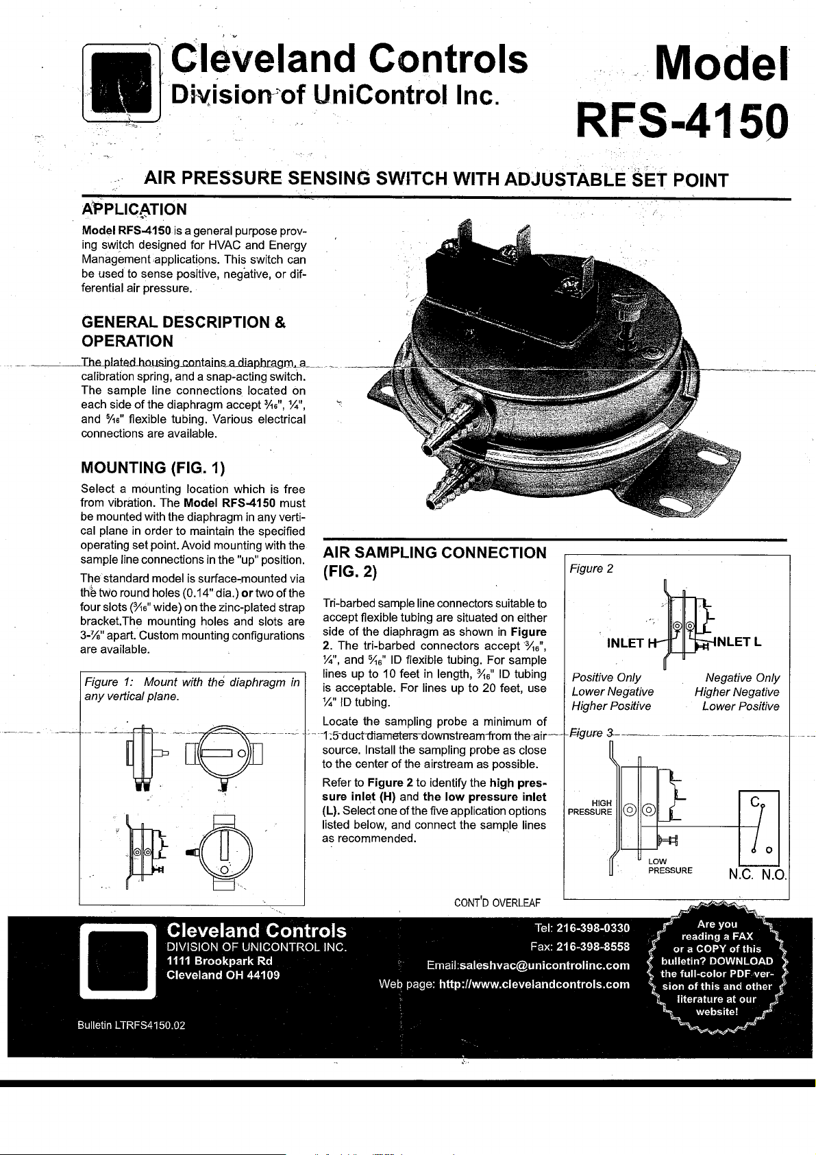
AIR SAMPLING CONNECTION
{FIG. 2)
via
of
the
Tri-barbed sample line connectors suitable
accept flexible tubing are situated on either
side
of
the diaphragm as shown
2.
The tri-barbed connectors accept
Y..",
and
o/;s"
ID
flexible tubing. For sample
lines up to 10 feet
in
is
acceptable. For lines up to 20 feet, use
Y.."
ID tubing.
Locate the sampling probe a minimum
--
-1;5-ductl:liameters-downstreamiromth.::.-.:H.·--+t=lctu.r:e
source. Install the sampling probe as close
to the center
Refer to Figure 2 to identify the high pres-
sure inlet (H)
(L).
Select one of the five application options
listed below, and connect the sample lines
as recommended.
of
the airstream as possible.
and
to
in
Figure
·o/is",
in
length,
11s"
ID
tubing
of
the low pressure inlet
RFS-4150
Figure 2
INLET
Positive Only
Lower Negative
Higher Positive
~---
HIGH
PRESSURE
---
LOW
PRESSURE
NLETL
Negative Only
Higher Negative
Lower Positive
------+
N.C.
/
0
N.O.
Positive
sample line to inlet
to the atmosphere. ·
Negative
sample line to inlet
to the atmosphere. · ·
Two Negative Samples: Connect the higher
negative sample
negative sample to inlet'
Two Positive Samples: Connect the higher
' positive sample to inlet
positive sample to inlet
\
One·Positive and One Negative Sample:
Connect the positive sample to inlet
nect, the negative sample to inlet
Figure 4
Pressure
Pressure
To
prove
excessive
c
e-_____-
~--------~~N~~c+-C-0-N-TROL
To
prove
insufficient
c
0--___:__""
~--------~N~C
Only:
Connect
H;
inlet L remains open
Only:
Connect
L;
inlefH
remains open
to
inlet L. Connect the lower
H.
\
~
Connect the lower
L.
H.
L,.
air
flow
or
pressure:
...,.NO
ALARM
air
flow
or
pressure:
JlO
CONTROL
.......
Q--1----
ALARM
the
the
Con-
ELECTRICAL CONNECTIONS
(FIGURES 3 &
Before pressure is applied to the diaphragm,
the switch contacts will be in the normally
closed (NC) position. Wire control and alarm
as
functions
shown
4}
in
Figure 4.
FIELD ADJUSTMENT
The adjustment range
Switch is 0.15±0.02" we to 5.0"wc.
To
adjust the set point,
screw
counterclockwise .until motion
stopped. Next, turn the adjusting screw 5
complete turns clockwis'll· to
spring.
From this
used forthei actual calibratibn.
represents
Please note:
switch, a digital manometer
suring device should be used to confirm the
actual set point. ' ·
p~t,
a~proximate'iy
To
of
an RFS-4150 Air-
t~rn
the adjusting
has
engage
;•
the next eight turns will be
Each full turn
0.61" we.
properly calibrate an air
or
the
other mea-
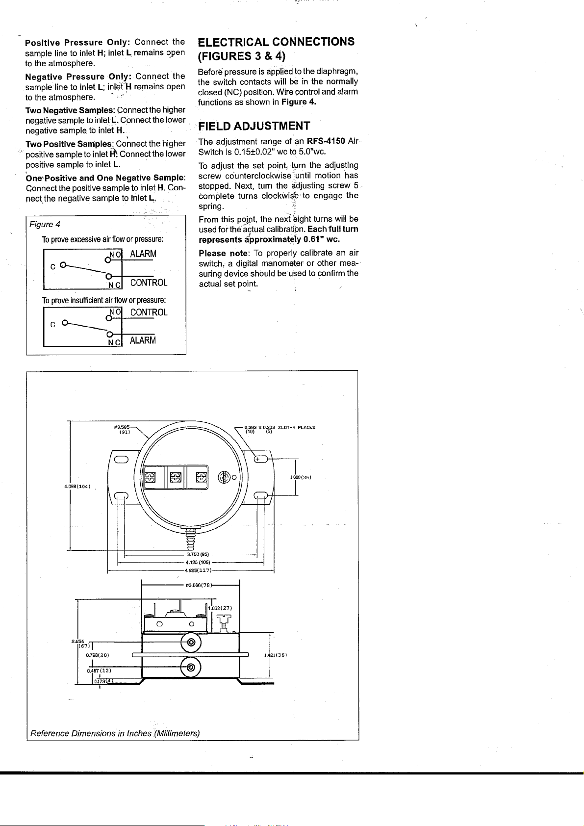
4.098(104)
1-----
Reference Dimensions in Inches (Millimeters)
.3.066(78)----1
 Loading...