

ClearWater SC27P Installation & Operation Manual

Ozone Systems
Installation & Operation Manual
SC27P
Corona Discharge Ozone Generator
Tested and certified by
WQA to NSF/ANSI 50 as a
component only.
Tested and certified by
WQA to NSF/ANSI 50 as a
component only.
ClearWater Tech, LLC.
Integrated Ozone Systems
850-E Capitolio Way, San Luis Obispo, Ca 93401 • 805-549-9724 • Fax: 805-549-0306 • E-mail: service@cwtozone.com • www.cwtozone.com
Copyright © 2005 - ClearWater Tech, LLC • Reproduction of any kind is prohibited • LIT135 • REV093010
1
THEORY OF OPERATION/PRODUCT DESCRIPTION CHAPTER 1
ClearWater Tech ozone systems are designed for safe, effective use in a variety of water treatment applications. The
SC27P ozone generator have been tested and certified by the Water Quality Association according to NSF/ANSI 50. Each
complete, integrated system may include the following components required for reliable, efficient ozone production and
can be divided into four general segments:
• Air preparation system • Ozone generator • Ozone injection/contacting • Ozone destruct
Air Preparation System
The ClearWater Tech SC27P ozone generator requires a source of clean, dry, oil-free, oxygen-enriched air for effective
ozone production. To meet that need, the built-in air preparation system employs pressure swing adsorption (PSA)
technology with an oil-less compressor to increase the concentration of oxygen and reduce the moisture content in the
feed gas (the air supplied to the ozone generator). This substantially improves the output capability of the ozone generator
and prevents premature failure of key internal components. These air preparation systems deliver 90%+/-3% oxygen
purity at -100°F dew point and at very low pneumatic pressures, minimizing noise and reducing compressor wear.
The air preparation system affects ozone production in grams per hour and more importantly ozone concentration, also
known as “percent by weight.” Since ozone is produced with oxygen, the greater the percent of oxygen that enters the
ozone generator will produce more grams per hour and concentration of ozone. Since the SC27P ozone generation system
incorporates PSA oxygen concentrator it will yield the highest grams per hour at the highest concentrations. Greater ozone
concentration equates to higher solubility of the ozone gas in solution, which will yield a greater oxidation potential.
Ozone Generator
The ClearWater Tech SC27P self-contained pressurized ozone generator is designed to supply high concentrations of
ozone gas (up to 10%) at 10 PSI. The oxygen feed gas produced by the air preparation system is supplied to the ozone
generator, which flows through the built-in flow meter. A stainless steel needle valve (located under the SC27P), is used
to maintain optimum pneumatic parameters inside the ozone reaction chambers. After this point the vacuum created at the
ozone injector draws the ozone gas into the water line. The ozone generator is equipped with a pressure switch, which
prevents operation if pressure within the reaction chambers drops below 9 PSI.
As the feed gas enters the fused, thermally protected reaction chambers inside the ozone generator, some of the oxygen
molecules are split while passing through the high voltage electrical field (the “corona”), forming single oxygen atoms
(O1). These oxygen atoms then recombine with other oxygen molecules in the air stream, forming ozone. The modular,
multiple reaction chamber design allows the ozone generator to keep working even if one of the chambers requires
service. Depending on the application, the ClearWater Tech ozone generator may be interlocked with an ORP controller,
PPM controller, pressure switch, timer or circulation pump.
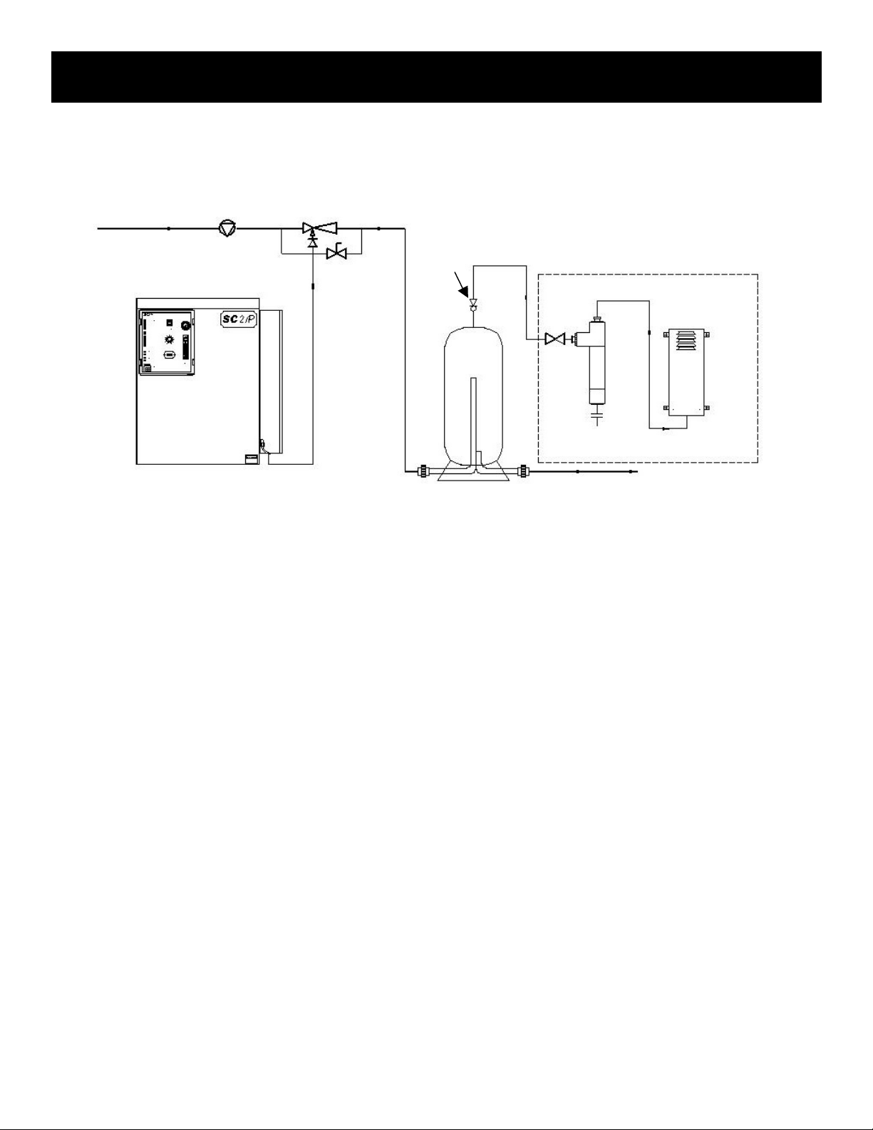
Booster Pump Ozone Injector
Water Flow Off Gas
Vent Optional Destruct System
Ozone Generator Ozone
Destruct
Unit
Water Trap

Theory of Operation/Product Description (continued)
2
Ozone Injection/Contacting
The ozone injector serves two purposes: One, it creates the vacuum
required to safely draw the ozone gas from the ozone generator and
two, it provides a means by which the ozone gas can become
dissolved in water. A very dynamic injection process is required to
effectively dissolve ozone in water.
ClearWater Tech injection systems use only Mazzei® injectors for
maximum mass transfer efficiency. The injector produces a
cavitation effect, enabling the ozone gas to join the water stream in
the form of extremely tiny bubbles. These bubbles must be as small
as possible in order to increase the ratio of bubble surface area to
the amount of ozone entering the water.
Depending on the application and the water treatment goals, a ClearWater Tech contacting system may also be required.
Some oxidation reactions take place so quickly that they are limited only by the rate at which the ozone is dissolved in the
water. Other reactions, such as disinfection, may require that proper ozone residual be maintained for a specific amount of
time. A correctly-sized contact vessel is used for this purpose.
Ozone Destruct
The ClearWater Tech off-gas destruct systems, consists of two components - the ozone destruct unit (a heated chamber
filled with manganese dioxide and copper oxide) and a water trap. Used in conjunction with a ClearWater Tech off gas
vent, the ozone destruct system is an effective way to vent the contact vessel(s) when it is impractical to send the off gas
to atmosphere or reintroduce it to the water.
3
SAFETY INFORMATION
CHAPTER 2
SAFETY WARNINGS
Two aspects of ClearWater Tech ozone generators represent potential dangers – ozone gas and high voltage electricity.
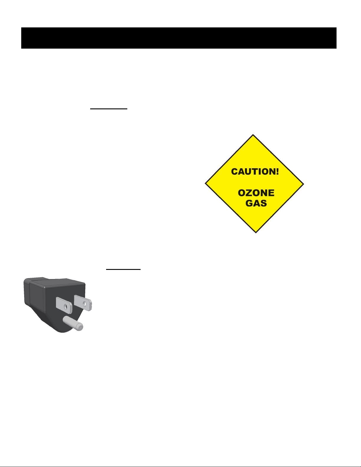
OZONE GAS -
WARNING: HIGH CONCENTRATIONS OF OZONE GAS ARE DANGEROUS
TO HUMANS. LOW CONCENTRATIONS CAN CAUSE IRRITATION TO THE
EYES, THROAT AND RESPIRATORY SYSTEM.
This ClearWater Tech corona discharge ozone
generator is designed to operate under a pressure
condition. While safety precautions have been taken,
entering the equipment area should be avoided if ozone
gas is detected. Ozone has a very distinctive odor and is
detectable at very low concentrations (0.02 ppm), which
is far below OSHA’s maximum permissible exposure
level of 0.1 ppm.
HIGH VOLTAGE -
WARNING: CLEARWATER TECH OZONE GENERATORS OPERATE
AT HIGH VOLTAGE. DO NOT TAMPER WITH OR DELIBERATELY
BYPASS THE COVER OR SAFETY SWITCHES BUILT INTO THE
OZONE GENERATOR UNLESS INSTRUCTED TO DO SO BY THIS
MANUAL. IF CONTACT IS MADE WITH OPERATING HIGH VOLTAGE
COMPONENTS, ELECTRIC SHOCK WILL OCCUR.
ClearWater Tech corona discharge ozone generators take line voltage and convert it to 48 VDC. A high voltage
transformer then boosts the voltage. While each ozone generator has a door switch and other safety interlocks, proper care
must be used by a qualified electrician when making any internal adjustments or performing any maintenance procedures.

4
IMPORTANT SAFETY INSTRUCTIONS
When installing and using this electrical equipment, basic safety precautions should always be followed, including the
following:
1.
READ AND FOLLOW ALL INSTRUCTIONS.
2.
SAVE THESE INSTRUCTIONS.
3.
All electrical connections should be made by a licensed, qualified electrician.
4.
Before attempting any electrical connections, be sure all power is off at the main circuit breaker.
5.
Install all electrical equipment at least five feet from any open body of water using non-metallic plumbing.
6.
Install check valves and a vacuum break to prevent water from contacting the electrical equipment.
7.
The electrical supply for this product must include a suitably rated switch or circuit breaker to open all
ungrounded supply conductors to comply with Section 422-20 of the National Electrical Code, ANSI/NFPA
70-1987. The disconnecting means must be readily accessible to the operator(s) but installed at least five
feet from any open body of water.
8.
Be sure to bond (ground) the system using the copper-bonding lug on the bottom of the ozone generator.
The system should be bonded with solid copper wire conforming to all local, state and national electrical
codes.
9.
The system should be sized appropriately for its intended use by a qualified professional familiar with the
application. This equipment must be validated by the manufacturer for its intended use; failure to do so
may void the warranty.

5
INSTALLATION PROCEDURES -
Getting Started
CHAPTER 3
Unpacking
Compare the ozone system equipment received to the packing list provided. Before beginning any
installation procedures, thoroughly inspect all components for damage. If damage is noticed,
promptly notify the freight carrier and request an on-site inspection. Inspect all packing materials
for small parts before discarding. Inspect all plumbing, fittings and tubing for packing material
that may have become lodged in openings.
Equipment Placement
• When placing the ozone system components in the equipment room, make sure to consider safety, maintenance
requirements, local building and fire codes, etc. The components should be easily accessible by the operators,
including equipment access doors and electrical hook-up boxes. All meters, gauges, indicator lights, and switches
should be visible and accessible. Dimensional drawings of each air preparation system and ozone generator are
included in Section A of the Appendix.
• The SC27P should be located as close as possible to the point of ozone injection. Ozone is an unstable gas and
will begin reverting back to oxygen very quickly. To determine the most favorable ozone injection point, the
following items should be considered:
• Located downstream of all other existing water system components.
• Located upstream of the residual sanitizer injection point (if so equipped).
• In a Sidestream plumbing configuration (see Figure 4-1) with recirculation, the pH adjustment
chemical injection point must be located downstream of the residual sanitizer injection point (if so
equipped).
• In a Full Flow plumbing configuration (see Figure 4-2) without recirculation, locate downstream of the
pH adjustment chemical injection point.
• Adequate protection from weather, dust and excessive heat.
• Like any electronic component, performance and longevity is enhanced by favorable operating conditions. Also,
since ozone generator is air-cooled, a relatively dust-free, well-ventilated area is required. No caustic chemicals
should be stored in the area surrounding the equipment. A minimum clearance of six inches from the vents on
either side of the ozone generator is required.
• The equipment is heavy and requires proper support. Therefore, a clean, dry, level vertical surface should be
provided for the SC27P. The system mounting bar should be securely fastened to the surface using the mounting
holes provided. Hang the SC27P from the wall mounting bar and level system on the wall with the leveling feet
provided on the backside of the system.
• The SC27P system is designed for specific voltage requirements, withstand typical outdoor elements and frequent
(though not constant) wash down, though should not be subjected to outdoor extremes including contact internally
with water and/or temperature extremes. Therefore, the equipment must be installed in an environment consistent
with the following operating parameters:
• Ambient temperature range: 20°F to 95°F continuous. If the temperature around the equipment
consistently exceeds 95°F, additional air-cooling must be provided.
• Humidity: 0 – 90% relative humidity, non-condensing environment
• Line voltage: +/-10% of rated input
Note: Equipment installed in extreme environmental conditions will void manufacturer's warranty.
• Allow room for the peripheral equipment (booster pump, injector manifold, contact vessel, etc.).

6
INSTALLATION PROCEDURES – Plumbing CHAPTER 4
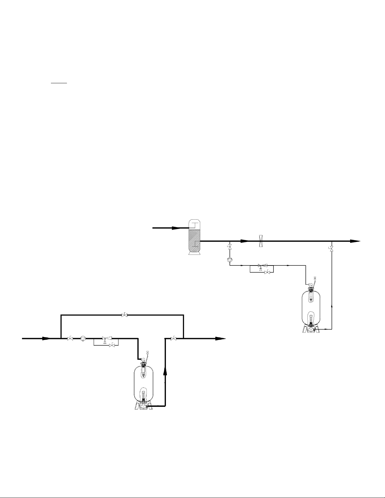
The ozone system should be plumbed using either a sidestream or full flow configuration. The sidestream
loop method takes a portion of the water from the main flow (see Figure 4-1) and diverts it into a
sidestream downstream of the filter (if so equipped). Ozone is introduced into the sidestream water and is
allowed contact time with the water before it is returned to the main flow at a point downstream of all other
equipment (heaters, solar panels, etc., if so equipped) in the circulation system. A booster pump is usually employed to
compensate for the flow restriction caused by the sidestream loop and the injector manifold. If a halogen-type residual
sanitizer is utilized, its injection point should be as far downstream as possible from the point at which the sidestream
water returns to the main flow. In a full flow configuration, the same system components are usually involved and appear
in the same order with respect to the direction of flow. However, all the water in the main flow is allowed contact time
with the ozone (see Figure 4-2). A booster pump may be necessary to maintain proper flow requirements. If employed, the
booster pump is located upstream of the point at which the ozone injector manifold is installed.
NOTES:
• Adequate use of unions and isolation valves is
strongly recommended to facilitate maintenance
and repairs.
• Use Schedule 80 PVC for all plumbing connections
wherever possible. Plumbing size requirements
are dictated by the water flow characteristics of
the system.
• Make sure to use proper plumbing practices and
secure all plumbing and system equipment
according to local codes.
• Ozone is a powerful oxidizer and will degrade certain
materials. Use ozone-compatible plumbing materials
for section(s) of the system that will come in contact
with ozone dissolved in water. The following is a list of
materials that are compatible with ozone:
• PVC • Stainless Steel (300 series)
• CPVC • Viton
• Kynar • EPDM
• Teflon • Concrete
• Depending on the application, other components (psi
gauge, flow meter, etc.) may be installed to assist in
monitoring system parameters.
Step 1: Arrange the ozone system equipment (booster pump, injector and contact vessel) according to mechanical print
or as dictated by equipment layout and serviceability considerations. Do not secure booster pump and contact
vessel to housekeeping pads at this point. Dry fit plumbing as appropriate to insure proper fit and location
before making permanent connections.
Step 2: Install a tee or plumbing saddle into the main water line after the filter (if so equipped) and before the flow
diversion mechanism. The purpose of the mechanism is to restrict water flow so water is diverted into the
sidestream (see Figure 4-1). If such a mechanism is not present in the system (such as a heater bypass valve,
etc.), it will require installation of a valve (butterfly, gate or ball) or a flow controller.
Step 3: Plumb a line from the tee or plumbing saddle to the booster pump. For serviceability of the equipment in the
sidestream loop, be sure to install an isolation valve between the tee or saddle and the booster pump.
Step 4: Plumb from the booster pump to the injector manifold. Make sure to note the correct direction of flow, indicated
by a blue arrow on the inlet side of the manifold body. The check valve assembly is strapped to the manifold
using wire ties. Remove the assembly; using Teflon® tape; install it onto the top opening of the injector.
Step 5: Plumb from the injector manifold to the inlet side of the contact vessel. To reduce possible backpressure to the
injector, minimize the number of elbows between the injector manifold and contact vessel. The contact vessel is
a specified size, determined by water flow requirements. ClearWater Tech contact columns and the 30, 40, 80,
and 120-gallon contact tanks have inlet and outlet fittings on the bottom of the vessel and are designated with
arrows showing the direction of flow. Note: The inlet and outlet arrows on the contact tanks are under the
base of the tank. The inlet on the 264, 463 and 850-gallon tanks is located at the top with the outlet at the
bottom.
Step 6: Using a tee or plumbing saddle, plumb from the outlet of the contact vessel back into the main water line. For
serviceability of the equipment in the side stream loop, be sure to install an isolation valve between the outlet
fitting on the contact vessel and before returning to the main water line.
Step 7: Secure the booster pump and contact vessel to solid mounting surfaces using appropriate hardware and
according to local codes. If installing a ClearWater Tech contact column, use a ClearWater Tech contact
Plumbing (continued)
7
column mounting kit and install according to the instructions below. If installing a contact tank, secure to a solid
horizontal surface using mounting flange or feet.
Step 8: Install the contact vessel venting system into the top of the vessel. If using the ClearWater Tech contact column,
the vent kit supplied includes fittings, a control valve and Teflon® tubing. The contact tank venting system
includes an air relief valve, fittings and a length of Teflon® tubing. Depending on conditions, the vented gas
may be directed to an ozone destruct system, to atmosphere or to the low-pressure side of the water system.
Note: Do not direct the tubing to the suction side of any pump in the system.
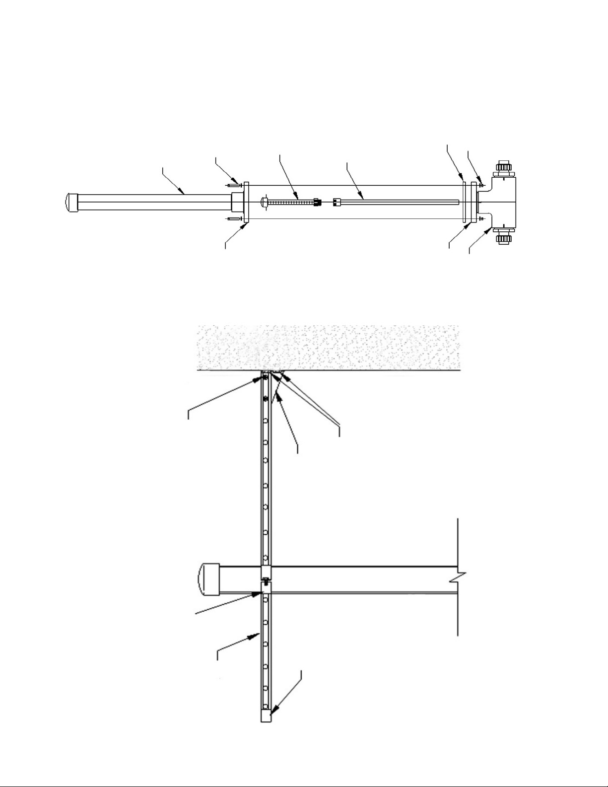
Contact Column Installation
(if so equipped)
Step 1: Make sure the following hardware items are included in the contact column mounting kit:
• 'L' bracket
• 1/2” concrete anchors
• 6” clamp assembly
• Unistrut bar
• Protective end cap
• Mounting hardware
Step 2: Referring to Figure 4-3, mark the two holes for mounting the 'L' bracket to the wall. The bracket should be
located so that the 6” clamp assembly will be approximately 12” from the top of the contact column. Drill a
1/2” hole at each of the marks, about 3 1/2” deep. Insert a concrete anchor into each hole with the threaded end
facing outward. Slip the 'L' bracket over the threaded ends of the anchors, followed by a washer for each
anchor. Secure the bracket to the wall by threading a nut onto each anchor and tightening.
Step 3: Cut the unistrut bar to the desired length and attach it to the 'L' bracket using hardware provided.
Step 4: Slip the two sides of the 6” clamp into the unistrut bar and then around the contact column. Tighten the retaining
bolt, securing the contact column to the unistrut bar.
Step 5: Slip the protective end cap over the exposed end of the unistrut bar.
Sidestream Plumbing Installation Diagram
Figure 4-1
Flow Diversion
Mechanism
Filter Isolation Isolation
Valve Valve
Booster Ozone Injector
Pump
Bypass Valve
Contact
Vessel
Isolation
Service Loop Valve
Isolation Isolation
Valve Ozone Injector Valve
Booster Bypass
Pump Valve
Contact
Vessel
Full Flow Plumbing Installation Diagram
Figure 4-2
Plumbing (continued)
8
Column
Column Flange Bolts &
Flange Washers(8 ea.)
Diffuser
Riser Tube
Base Flange Gasket
Base Flange Nuts &
Washers (8ea.)
Contact Column Exploded View
Figure 4-4
Contact Column Installation Diagram
Figure 4-3
6” Clamp Assembly Bolts, nuts &
with bolt & Nut washers (2ea.)
Unistrut
(cut to length)
Unistrut “L” Bracket
Protective
End cap Concrete Anchors
with nuts &
washers (2ea.)
 Loading...